Embed Size (px)
DESCRIPTION
six months training report
Citation preview

PROJECT REPORT
SIX MONTHS INDUSTRIAL TRAINING
At
ACCURATE AUTO PRODUCTS PVT. LTD.
GURGAON
SUBMITTED BY: ROHAN KAPUR
ROLL NO; UE109059
B.E. {MECHANICAL ENGINEERING}
UIET
PANJAB UNIVERSITY

S.no. Content Page no.
1 Acknowledgment 12 Preface
23 Introduction To Company
3 4 Location
45 Products & Clients
56 Various Shops
107 Sheet Metal Forming
118 Machine Shop
179 Weld Shop 2510 Quality Department
3011 Troubleshooting
33

12 Project 3613 Conclusion 4014 References 41
AKNOWLEDGMENT
I take great pleasure in presenting this report on
project work of Bachelor of Engineering from
U.I.E.T, Panjab University done at Accurate Auto
Products Pvt. Ltd. Gurgaon.
I am thankful to Mr. VISHAL MALHOTRA
with whose support and expert guidance I have been
able to submit this project. He helped me a lot
during span of my training. It was great and
knowledgeable experience under their Guidance.

I am highly grateful to the staff and management
of Accurate division for being so cooperative and
support.
PREFACE
Practical training is of utmost importance. The
object of undergoing this training was to get familiar
with the weary waters of the industry and to learn
how to put theory into practice. I have been greatly
privileged to have undergone training at Accurate
Auto Products Private Limited. This report contains
work on quality control assurance and reliability.

INTRODUCTION TO COMPANY
Accurate Auto is an ISO 9001:2000 BSI certified company established in 1989.They are leading manufacturer of sheet metal components, turned components, tubular components and assemblies for two wheeler and four wheelers automobile companies.
AAPPL has two plants equipped with the latest tools and ability to design and manufacture as per Indian and international standards.
In able guidance of Mr. Bipul Kumar Bedi (Managing Director, Accurate Auto Products Pvt. Ltd.). The company's stress on stringent Quality Control procedures is evident from its certification for International Standards ISO 9001: 2000 (NQA-QSR) for research and development. The company's Quality Policy & Objectives are very clear with regards to On-time deliveries and 0% Re-work.

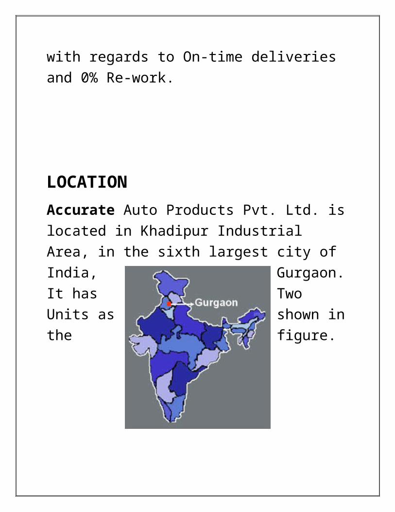
LOCATION
Accurate Auto Products Pvt. Ltd. is located in Khadipur Industrial Area, in the sixth largest city of India, Gurgaon. It has Two Units as shown in the figure.

CLIENTS AND PRODUCTS
India Yamaha Motors Pvt. Ltd., Surajpur
Omax Autos Ltd Speedomax Automax Patton International Ltd. Purolator Filter Ltd. Honda Motorcycle & Scooter
India (P) Ltd. Hema Engineering Industries
Ltd. Century Auto Engineering Pvt.
Ltd
Also supplies to customers who engage in manufacturing of Jigs, Fixtures & Spares for Paint Shop, Frame assay, and Maintenance departments.


INTRODUCTION TO VARIOUS SHOPS
In AAPPL, the company is engaged with many manufacturing products by using different types of processes such as Bending, Punching, Milling Drilling, Turning, Welding, Press, Using CNC etc.
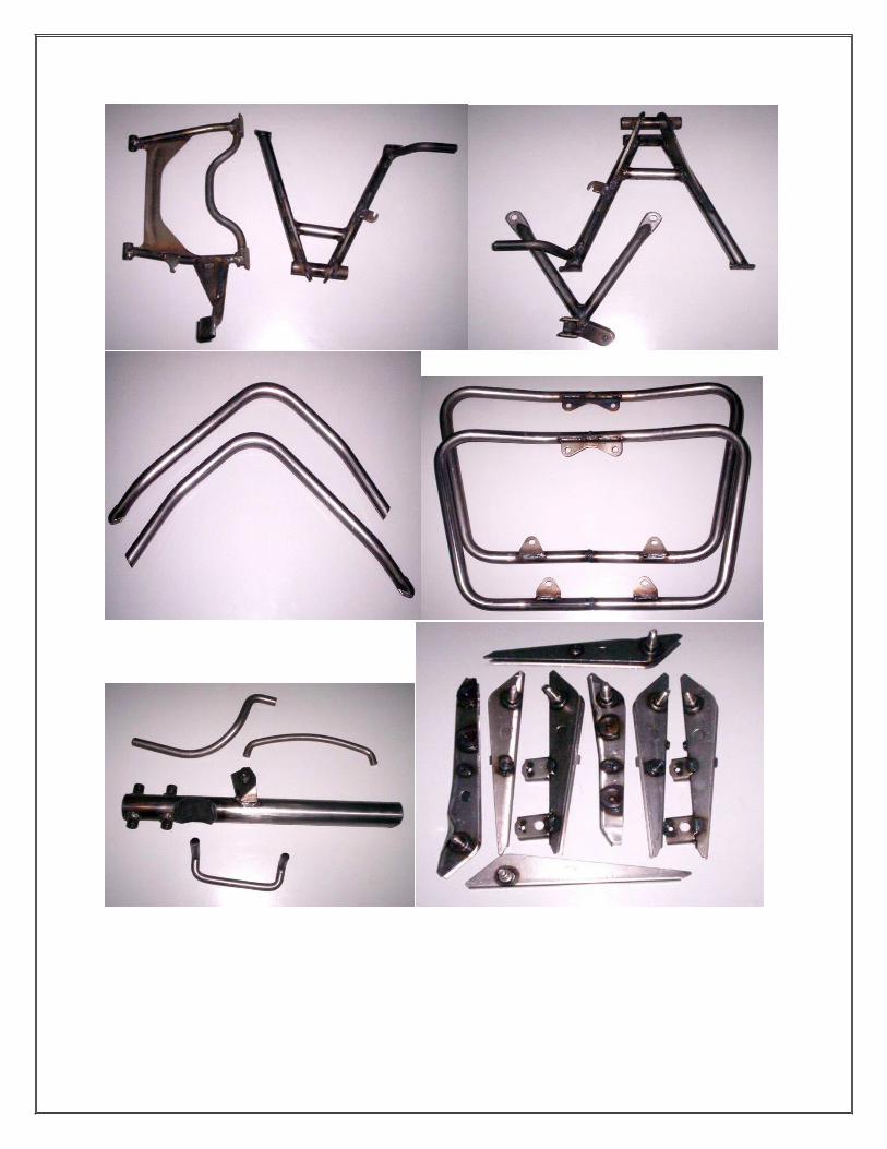
Company is engaged in manufacturing of
Sheet metal ComponentsTurned and Machined ComponentsWelded AssembliesTubular ComponentsBuilders Hardware parts
So these processes can be done using various shops in AAPPL:
o Press line Shopo Machine Shopo Welding Shop

SHEET METAL PROCESS
The raw material for sheet metal manufacturing processes is the output of the rolling process. Sheets of metal are sold as flat, rectangular sheets of standard size. Therefore the first step in any sheet metal process is to cut the correct shape and sized ‘blank’ from larger sheet. Sheet metal processing is an important process for larger structural parts like boilers, turbines, bridges and ships. Most of these products have metal casings that are made by cutting and bending sheet metal.
Sheet metal manufacture is mostly performed on a press and parts are formed between two die. The top die is called a punch. Parts are economical and easy to mass produce. Sheet metal is usually formed cold, however warm or hot working of parts, (particularly plate), is possible. Sheet metal manufacturing produces parts that typically have high strength, good surface and accurate tolerances:
Thickness of sheet metal varies from 0.4 mm to 6 mm .Thickness of plate stock > 6 mm
There are 3 major classes of processes of sheet metal working.
Cutting: Cutting is the use of shearing forces to remove material from a work piece. Technically not a metal forming process, but of extreme industrial importance. Bending: Bending is the forming of a sheet metal work about an axis. Deep Drawing: Deep drawing is the forming of a cup or box with a flat base and straight walls, from a sheet metal blank.
Mechanical behavior of metal is important to understand when manufacturing sheet metal products. Generally a desirable property for metals is a large plastic deformation before necking. When necking of the metal occurs, diffuse necking is preferred over localized necking. A high total elongation of the material before fracture is also desirable for sheet metal forming. Some metals such as low carbon steels and aluminum-magnesium alloys may experience yield point elongation. This uneven yielding of the material may produce

stretcher strains. These lines are actually small depressions in the material not acceptable in situations where surface finish matters. Grain size, structure and orientation are also important in a sheet metal work piece. Grains will affect the properties of the metal as well as surface finish.
There are tests that are used specifically to determine the formability of sheet metal. One common test is the cupping test. A specimen is secured over a round die cavity and a steel ball is pushed into the specimen until fracture of the material occurs. The greater the distance that the sheet metal can plastically deform before fracture, the greater the sheet's formability.

Anisotropy is the directional variation of mechanical properties. The material will react differently to stress applied in one direction than it would to the same stress applied in a different direction. If a sheet is isotropic, then its properties are the same in any direction. Cupping tests can be used to determine anisotropy. If the fracture occurring due to the applied force through the round ball is circular, then the sheet is isotropic. If a straight fracture occurs, this means that the sheet is anisotropic.
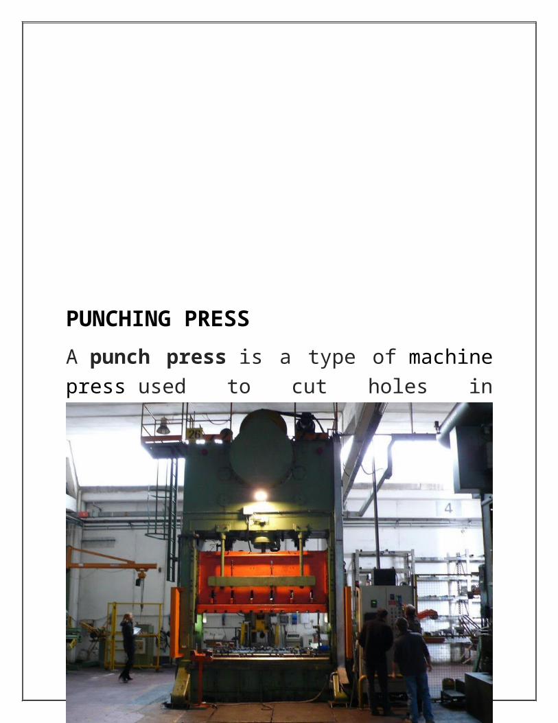
PUNCHING PRESS
A punch press is a type of machine press used to cut holes in material. It can be small and manually operated and hold one simple die set, or be very large, CNC operated, with a multi-station turret and hold a much larger and complex die set.
Gap frame press for sheet metal working

The punch press is characterized by parameters such as:
Frame type Mechanism of delivering power to the ram
(mechanical, electro-mechanical or hydraulic) Size of working area (e.g., 2500 x 1250 mm) Single or multiple station Force rating (for example, 20 tons) The type of tool shop and its capacity (e.g., store
revolving type, capacity 34 tool) Speed of movement without shock (speed-load
displacement) Maximum weight of work piece Safety features Power consumption The type of software

MACHINE SHOP
Machining is any of various processes in which a piece of raw material is cut into a desired final shape and size by a controlled material-removal process. The many processes that have this common theme, controlled material removal, are today collectively known as subtractive manufacturing, in distinction from processes of controlled material addition, which are known as additive manufacturing.
Radial Drilling Machine

The Machine shop deploys Lathes,Milling machines and Drills in the production line to obtain various parts
CNC Operated Milling machine

SINGLE SPINDLE MECHANICAL LATHE
The general purpose single spindle automatic lathes are widely used for quantity or mass production of high quality fasteners; bolts, screws, studs etc., bushings, pins, shafts, rollers, handles from long bars or tubes of regular section and also often from separate small blanks. Unlike the semiautomatic lathes, single spindle automats are:
• Preferably and essentially used for larger volume of production i.e., large lot production and mass production
• Used always for producing jobs of rod, tubular or ring type and of relatively smaller size.
• Run fully automatically, including bar feeding and tool indexing, and continuously over a long duration repeating the same machining cycle for each product
• Provided with upto five radial tool slides which are moved by cams mounted on a cam shaft
• Of relatively smaller size and power but have higher spindle speeds.
Lathe specifications· Distance between centers· Swing The specification for any lathe needs to quote the essential criteria needed for its performance and capacity.
Maximum swing Distance between centers Cross slide capability Top slide requirement Type of control system –Analogue ,digital or
CNC Accuracy Work mounting devices (chuck or collet) Tail stock type Screw cutting capability Miscellaneous accessories.

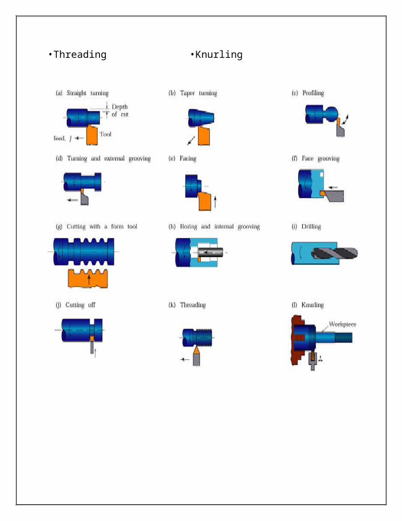
There are different types of machine operations that are performed on a lathe:•Turning •Tapering •Profiling •External grooving
•Facing •Face Grooving • Boring •Drilling
•Cutting Off •Reaming •Broaching •Honing
•Threading •Knurling

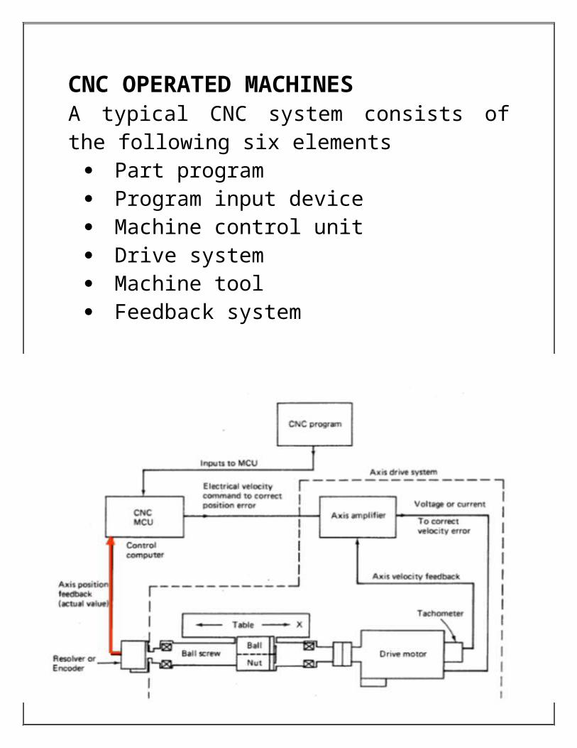
CNC OPERATED MACHINES A typical CNC system consists of the following six elements
Part program Program input device Machine control unit Drive system Machine tool Feedback system

By integrating a computer processor, computer numerical code, allows part machining to be edited and stored in the computer memory & permitting diagnostics and quality control functions during the actual machining. All CNC machining begins with a part program, which is sequential instructions or coded commands that direct specific machine functions and tool positioning. The part program may be manually generated or, more commonly generated by computer aided (CAD/CAM) part programming systems. The program is fed to MCU using input devices, containing commands to set machine parameters; speed, feed and other relevant information. The Rectangular coordinate system allows the mathematical plotting of points in space. These points or locations are called coordinates. Which in turn relate to the tool center and dictate the Tool Path through the work.

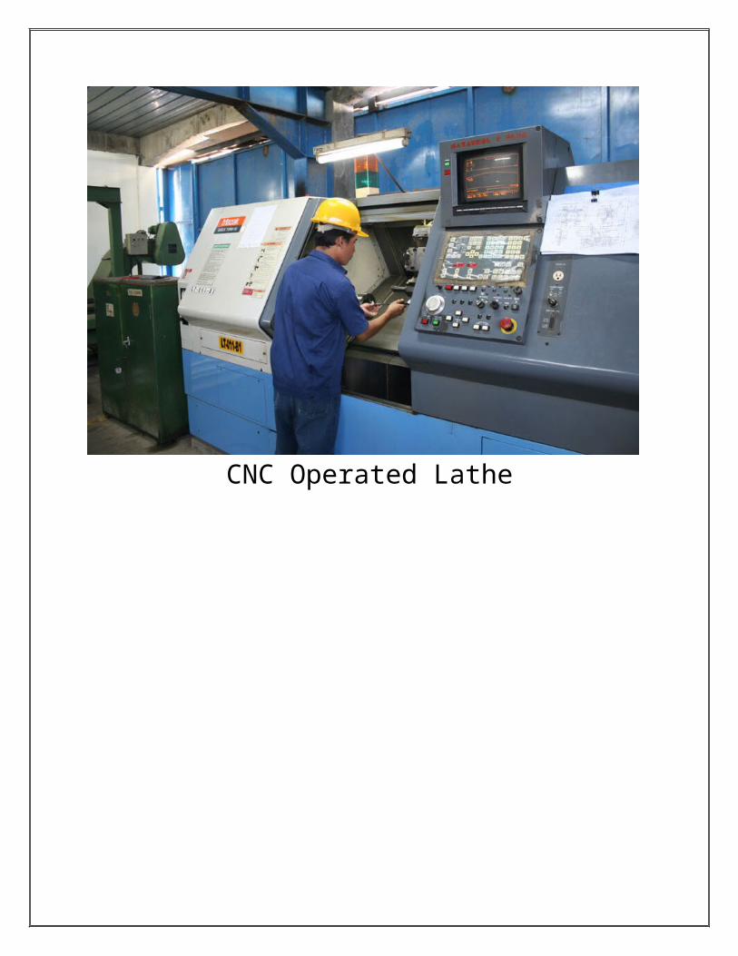
CNC Operated Lathe

WELD SHOPWelding is a fabrication or sculptural process that joins materials, usually metals or thermoplastics, by causing coalescence. This is often done by melting the workpieces and adding a filler material to form a pool of molten material (the weld pool) that cools to become a strong joint, with pressure sometimes used in conjunction with heat, or by itself, to produce the weld. This is in contrast with soldering and brazing, which involve melting a lower-melting-point material between the workpieces to form a bond between them, without melting the work pieces.
With most, you use a pedal to adjust your amount of heat and hold a filler metal with your other hand and slowly feed it. The electrode holder holds the electrode as it slowly melts away. Slag protects the weld puddle from the outside world. Flux-Core is almost identical to stick welding except once again you have a wire feeding gun, the wire has a thin flux coating around it that protects the weld puddle.
Welding is a potentially hazardous undertaking and precautions are required to avoid burns, electric shock, vision damage, inhalation of poisonous gases

and fumes, and exposure to intense ultraviolet radiation.
One of the most common types of arc welding is shielded metal arc welding (SMAW); it is also known as manual metal arc welding (MMA) or stick welding. Electric current is used to strike an arc between the base material and consumable electrode rod, which is made of filler material (typically steel) and is covered with a flux that protects the weld area from oxidation and contamination by producing carbon dioxide (CO2) gas during the welding process. The electrode core itself acts as filler material, making a separate filler unnecessary.

GAS METAL ARC WELDINGMetal inert gas welding (MIG) was also known as gas metal arc welding (GMAW) or metal active gas welding (MAGW). MIG welding process is a semiautomatic process that used consumable wire electrode and shielding gas. The wire electrode is continuously and automatically fed through the welding gun. The wire electrode diameters used in this welding process is around 0.8 to 6.5 mm and it is depends on the thickness of the part to be joined. Gases that normally used as shielding gases can be inert gases such as helium and argon or active gases such as carbon dioxide. Gases used during the welding process depend on the type of metal to be weld where inert gases for aluminium alloys and stainless steels but carbon dioxide for low and medium carbon steels. Shielding gases functions to eliminate slag covering the welded part. As MIG welding save more time compare to Shielded metal arc welding (SMAW), it is widely used in factories.MIG welding operate by creating a short circuit between the wire electrode (anode) and the metal being weld (cathode). This short circuit will produce enough heat energy to melt the metal and allow them to join together.

The process may be automatically controlled by using PLC where the MIG welding machine table is able to move in both X and Y axis according to the welders will. During the welding process, MIG welding produced spatter which is hot enough to melt the low melting point material such as aluminum. However, spatter is required as it helps to create a good joint between workpieces. Thus, the welding jig should be able to withstand the heat produced by the spatter so that it can last long.Beside spatter, MIG welding or even any welding process also cause distortion to the workpiece especially in sheet metal which is normally used as the workpiece. Commonly, the distortion can be reduced by using a proper welding jig. The distortion normally as below;
The process is versatile and can be performed with relatively inexpensive equipment, making it well suited to shop jobs and field work. Weld times are rather slow, since the consumable electrodes must be frequently replaced and because slag, the residue from the flux, must be chipped away after welding.

Diagram of arc and weld area, in shielded metal arc welding1. Coating Flow2. Rod3. Shield Gas4. Fusion5. Base metal6. Weld metal7. Solidified Slag
QUALITY ENGINEERING
DEPARTMENT
Discipline that deals with the analysis of a
manufacturing system at all stages, to improve the
quality of the production process and of its output.
Quality engineering receipt (formally known as
Quality Engineering Department) is divided into two
fields
1. Suppliers Quality
2. In-House Quality
SUPPLIERS QUALITY
Suppliers section consists of maintaining the quality of
products that are being supplied by suppliers. It
contains inspection of the raw materials being supplied
by suppliers. It also includes discussion regarding
delay of raw material and defective parts supplied.
Subsequent actions are taken if the supplied products
being supplied are found defective and inspectors from
the industry are sent regularly to avoid such defects.
This inspection is regularly done by the industry so
maintain good quality supply and sound relationship
with suppliers.
IN – HOUSE QUALITY
In house quality is embedded into every department of
the industry. As such there are three departments that
are:
Sheet Metal Shop
Machine Shop
Welding Shop
QUALITY ENGINEERING ASSEMBLY
Quality Engineering Assembly consists of three
quality posts. Each Quality Posts are situated at every

intervals of the assembly line. Each Quality post has a
certain responsibility of maintaining the quality of the
Product being manufactured in the industry.
P.D.I. (Pre Dispatch Inspection)
P.D.I (Pre Dispatch Inspection) is the final quality post
which carries a major responsibility of dispatching the
final product as manufactured by the assembly line.
This is similar to giving final touches to the jewelry
being sold. This department carries rigorous checks as
per the pre-designed checklist prior to dispatch of
machinery.
P.D.I acts as one of the major diagnosing center for
every daily to daily outgoing failure and scrutinizing
them and hopefully trying to remove these failures.
This way forthcoming problems reported by dealers

are reduced. This helps to maintain a healthy
relationship with dealers and customers.
TROUBLESHOOTING Some of the common defects in the work piece & problems with machinery that occur during manufacturing are enlisted below, along with measures taken to overcome these hindrances.
Sheet Metal Forming Defects
Static defects, such as surface imprints, are not process-related but instead are caused by contaminated die or tool faces. These defects are corrected simply by cleaning the die or tool surface before stamping.
Dynamic defects are process-related and are caused by the forming process. For example, cracking and necking commonly occur when formability of the deformed sheet material is limited. Side-wall and flange wrinkles are caused by high tangential compressive stresses in the sheet. Marking lines occur when sheet material undergoes high tensile stresses as it flows over sharp tool corners. Fall-in is commonly observed where areas of high strain rate are surrounded by large areas of low strain rate.

Dynamic defects can be corrected by controlling process variables (forming forces, forming speeds, and friction forces) and incoming sheet coil properties.
Cracks near the punch region are minimized by increasing punch radius and lowering punch load.
Wrinkling of the flanges or the edges of the cup resulting from buckling of sheet due to circumferential compressive stresses is minimized by using sufficient hold down pressure to suppress the buckling.
Production Lathe (Traub) breakdown Vibration caused by stock not centered properly.
Top jaws holding the job not symmetric with the rotation axis and therefore causes imbalance.
This vibration is minimized by reducing RPM, replacing worn out bearings at the headstock along with belts of pulleys and overall lubrication.
Poor Accuracy. Guide ways of the internal parts of the chuck wearing out because of dirt from burrs and chips and no periodic maintenance.

Recondition the chuck /Replace the chuck with new, reducing chucking force and lubricating guides at the beds helps increase accuracy.
Weld defects For welding different parts, the worker holds job
in jig that is unable to properly clamp all products. This induces thermal stresses and spoils the joint of work piece. This problem is overcome by designing a proper MIG welding jig that can clamp all work pieces.
Reduced supply of shelter gas causes oxidation of the weld pool which creates weak joints. The gas used is CO2 and it’s supplied to 8 welding guns through separate cylinders, this causes problem as the cylinders get exhausted in short time. Thus a gas tank is installed which caters to feeding all the present equipment.

PROJECT
Customized design of MIG welding Jig. This MIG welding jig can also be fabricated using stainless steel block, aluminum bar, and screws. Jig will be designed in a way that it is easy to use and reliable to the user without limiting their skill.
PROBLEM STATEMENTWelding jig is important in reducing the effect of defect such as thermal stress in welding part. In the welding shop, most of the sheet metal is weld defected.This is mostly due to the improper welding jig that is unable to clamp the sheet metals. Thus, a proper welding jig should be produced as soon as in order to overcome this problem and help to increase the accuracy.The present jig also cannot clamp workpieces with different thickness.

This project is important in to hold the work piece together in one straight line and reduce the distortion due to thermal stress. This jig also designed in such order that it is able to clamp different thickness of workpieces as well as rod.
PROJECT OBJECTIVESThe objectives of this project are:To design and fabricate a MIG welding jig that can hold the workpieces such as sheet metal and plate in a rigid position so that the distortion due to thermal stress can be minimized beside can clamp different thickness of work piece.To design and fabricate a MIG welding jig that can hold rod beside sheet metal and plate.
PROJECT SCOPE Design for the use of the MIG welding
machine in welding research lab. The jig can hold different thickness of
workpiece. The jig can hold rod. The jig can be move so that a different distance
of gap between workpieces can be achieved.

The jig able to give the measurement for the gap between workpieces.
Materials used: aluminum bar, steel ruler, and screws and bolts.
CONSIDERATIONS DESIGNWhen designing MIG welding jigs, we must consider:
1. Expansion of the workpiece due to the heat during welding should not affect the clamping effect of the jig.
2. Do not allow the spatter to fall on threaded part of the jigs so that it will not jam.
3. Ensure that the workpiece can be unload from the jig as soon as the welding process finish.
4. Provide a spatter grooves so that the workpiece will not join together with the base plate.
Thermal expansion coefficient indicates how much a material expands for each degree the temperature increase. Stainless steel has low thermal expansion coefficient after copper which mean it will only involve a slight expansion due to the heat.

Thus, we can conclude that the most suitable material to be used as MIG welding jigs in this project is stainless steel which will be able to withstand the high temperature of the spatter produced during MIG welding beside has lower weight than other two metals and less expansion due to increase of temperature.CONCEPTThe screening process considers several criteria which are durability, cost, ease of manufacturing, ease of operating, space optimization and functionality. Based on above aspects this was designed by using the screw clamp which is the cheapest clamp type. The advantage of this concept is its ability to clamp workpiece with different thickness as well as rod.This design has two extra features which are adjustable gap between workpiece which can be measured on the given scale. The disadvantages of

this design are, it involves several complicated parts and takes a longer clamping time compared to previous clamping system.CONCLUSIONFor the setup of an industry and its smooth running, various factors are to be considered. In case of this Auto industry, safety measures are taken to be in special attention to minimize any type of risks/ accidents. For the day to day maintenance jobs of the Machine, various tools and tackles are used. To minimize defects due to human error, the workers should be skilled in their field.
There are problems that occur in the semiautomatic gas metal arc welding process which is the last operation on the job. Thus any defects formed here, damage the whole work piece, 80% of the reject cases are due to welding defects. To get a best results, the workers must know the angles that are used, concentration, and the movement of the electrode and speed of moving the electrode. The thickness of the metal and type of the electrode used are prime factors in welding process.

REFERENCES:
Google.com
Manufacturing Process by P C Sharma
Accurateauto.com
Wikipedia.org


![Man of steel [autosaved] [autosaved]](https://img.pdfslide.us/doc/110x75/5551d154b4c905922b8b51a1/man-of-steel-autosaved-autosaved.jpg)


![Mathematics of nyquist plot [autosaved] [autosaved]](https://img.pdfslide.us/doc/110x75/55a6a9751a28ab056b8b468d/mathematics-of-nyquist-plot-autosaved-autosaved.jpg)

![Arc therapy [autosaved] [autosaved]](https://img.pdfslide.us/doc/110x75/55a758ab1a28ab67458b4586/arc-therapy-autosaved-autosaved.jpg)
![NovoNail PPT1 [Autosaved] [Autosaved]](https://img.pdfslide.us/doc/110x75/587df8121a28abab7e8b62bb/novonail-ppt1-autosaved-autosaved.jpg)
![Common alerting protocol overview for pagasa 2016 [autosaved] [autosaved]](https://img.pdfslide.us/doc/110x75/589a945b1a28abae648b5cbb/common-alerting-protocol-overview-for-pagasa-2016-autosaved-autosaved.jpg)

![Base isolation.ppt [Autosaved] [Autosaved]](https://img.pdfslide.us/doc/110x75/587319861a28ab673e8b5ddd/base-isolationppt-autosaved-autosaved.jpg)
![Pic microcontroller [autosaved] [autosaved]](https://img.pdfslide.us/doc/110x75/547c27a4b37959582b8b4f25/pic-microcontroller-autosaved-autosaved.jpg)

![Aintree twitter ppt [autosaved] [autosaved]](https://img.pdfslide.us/doc/110x75/55d7693dbb61ebc6238b466d/aintree-twitter-ppt-autosaved-autosaved.jpg)


![TASAWWUR ISLAMI-Eksekutif ILIA [Autosaved] [Autosaved]](https://img.pdfslide.us/doc/110x75/55cf94c9550346f57ba46428/tasawwur-islami-eksekutif-ilia-autosaved-autosaved.jpg)

![Hero Cycles [Autosaved] [Autosaved]](https://img.pdfslide.us/doc/110x75/577cc0551a28aba7118fb6fe/hero-cycles-autosaved-autosaved.jpg)

![Adk presentation 11 march 2017 [autosaved] [autosaved]](https://img.pdfslide.us/doc/110x75/58d0ced61a28ab866c8b6b5b/adk-presentation-11-march-2017-autosaved-autosaved.jpg)

![Grand Final Atlantic Corridor poster presentation [Autosaved] [Autosaved]](https://img.pdfslide.us/doc/110x75/58ef446b1a28ab031e8b458b/grand-final-atlantic-corridor-poster-presentation-autosaved-autosaved.jpg)