Embed Size (px)
Citation preview
7 6 0 - 0 0 0 6 0 1 R e v A
B r o a d A c c e s s
L C T I n s t a l l a t i o n a n d A d m i n s t r a t i o n G u i d e

BroadAccess LCT Installation and Adminstration Guide
760-000601 Rev A 000601a_LCT_rel_6.doc 04-Aug-05 3:15 PM
Page i
Table of Contents
1. Introduction _____________________________________________________________ 5
1.1. Related Publications ______________________________________________ 6
1.2. Conventions and Terminology ______________________________________ 6
1.3. List of Acronyms and Abbreviations Used in this Guide_________________ 10
2. BroadAccess System Overview _____________________________________________ 1
2.1. Local Craft Terminal Overview _____________________________________ 3
3. System Requirements _____________________________________________________ 5
3.1. Hardware Requirements ___________________________________________ 5
3.2. Software Requirements____________________________________________ 5
4. Installing LCT ___________________________________________________________ 7
4.1. Installing and Configuring the Null Modem___________________________ 15
4.2. Configuration Required for Management using Dial-Up Connections ______ 21
4.2.1. Hardware Setup _______________________________________ 22
4.2.2. NE Preparations _______________________________________ 22
4.2.3. LCT Computer Windows-Level Preparations ________________ 23
4.2.4. LCT Preparations ______________________________________ 23
4.2.5. Configuring the Dial-up Connections for each NE ____________ 26
4.3. Upgrading LCT_________________________________________________ 27
4.4. Uninstalling LCT _______________________________________________ 27
4.5. Uninstalling Oracle ______________________________________________ 28
4.5.1. Removing a Single Oracle Home__________________________ 31
4.6. Installation Error Messages________________________________________ 36
5. Opening an LCT Session__________________________________________________ 39
5.1. Logging on and Connecting to the BroadAccess NE ____________________ 39
5.2. Creating and Configuring a BroadAccess 40 Network Element ___________ 41
6. User Interface __________________________________________________________ 45
6.1. LCT Work Area ________________________________________________ 46
6.2. Menu Bar and Toolbar ___________________________________________ 46
6.3. Creating Reports ________________________________________________ 51
6.3.1. Hiding Columns of Data in Tables ________________________ 51
6.3.2. Using the Advanced Database Filter _______________________ 52
Table of Contents
Page ii August 2005
760-000601 Rev A
6.3.3. Using the Report Designer _______________________________ 55
7. Security Management_____________________________________________________ 63
7.1. Configuring User Properties _______________________________________ 64
7.1.1. Adding, Deleting and Modifying Users' Properties ____________ 64
7.1.2. Changing User Passwords _______________________________ 67
7.2. Configuring LCT User Properties ___________________________________ 68
7.2.1. Adding, Deleting and Modifying LCT Users' Properties ________ 69
7.2.2. Changing LCT User Passwords ___________________________ 73
8. IP Networking __________________________________________________________ 75
8.1. Configuring IP Addresses _________________________________________ 78
8.2. Configuring SNMP Communities Settings ____________________________ 86
8.3. Configuring the System's ATM Inband Interface _______________________ 87
8.4. Configuring the System's PPP Interface ______________________________ 87
8.5. Changing a CU's Network IP Address Using HyperTerminal _____________ 88
9. Using the Telnet Command Line Interface ____________________________________ 91
9.1. Opening the Telnet Session with the RU______________________________ 91
9.2. Using the Command Line Interface__________________________________ 92
9.3. Viewing RU Alarms via Telnet _____________________________________ 92
9.4. Viewing RU Inventory Information via Telnet _________________________ 93
9.5. Downloading and Swapping Software via Telnet _______________________ 93
10. Index__________________________________________________________________ 97
BroadAccess LCT Installation and Adminstration Guide
760-000601 Rev A August 2005
Page iii
List of Figures Figure 1. BroadAccess Standard Cage General View and Card Locations __________________ 7
Figure 2. BroadAccess Mini Cage General View and Card Locations _____________________ 8
Figure 3. BroadAccess CAGE40-M Standard Cage ___________________________________ 2
Figure 4. Dial-Up Connection Groups Window _____________________________________ 25
Figure 5. Domain/Site Properties Dialog Box _______________________________________ 43
Figure 6. NE Properties Dialog Box - General Tab ___________________________________ 43
Figure 7. NE Properties Dialog Box - IP Tab _______________________________________ 44
Figure 8. NE Properties Dialog Box - Telephone of NE Tab ___________________________ 44
Figure 9. LCT Main Window____________________________________________________ 45
Figure 10. Field Chooser Dialog Box ______________________________________________ 52
Figure 11. Advanced Database Filter_______________________________________________ 54
Figure 12. Report Designer Dialog Box - Options Tab _________________________________ 58
Figure 13. Report Designer Dialog Box - Colors Tab __________________________________ 59
Figure 14. Report Designer Dialog Box - Fonts Tab___________________________________ 60
Figure 15. Report Designer Dialog Box - Behaviors Tab _______________________________ 61
Figure 16. Users Window _______________________________________________________ 66
Figure 17. Change Password Dialog Box ___________________________________________ 67
Figure 18. LCT Users Window ___________________________________________________ 70
Figure 19. Authorized Schedule Window ___________________________________________ 72
Figure 20. Typical IP Networking Configuration using Default IP Addresses and Subnet Masks ________________________________________________________ 78
Figure 21. IP Address Settings Window - CU Interfaces Tab ____________________________ 81
Figure 22. IP Address Settings Window - RU Interfaces Tab ____________________________ 84
Figure 23. COM1 Port Location __________________________________________________ 89
Table of Contents
Page iv August 2005
760-000601 Rev A
List of Tables Table 1. Element Naming Conventions used in the ClearAccess+, LCT and NE
Operation Graphical User Interface_________________________________________ 8
Table 2. Conventions used in this Guide___________________________________________ 10
Table 3. Dial-Up Connection Groups Window Settings _______________________________ 25
Table 4. LCT Installation Error Messages__________________________________________ 36
Table 5. Menu Bar and Toolbar Commands ________________________________________ 46
Table 6. Filter Window Generic Buttons___________________________________________ 53
Table 7. Report Types and Access Methods ________________________________________ 55
Table 8. User Security Levels ___________________________________________________ 63
Table 9. Users Window Settings _________________________________________________ 66
Table 10. User Security Levels ___________________________________________________ 68
Table 11. LCT Users Window Settings_____________________________________________ 71
Table 12. Authorized Schedule Window Settings_____________________________________ 72
Table 13. BroadAccess CU and RU Default IP Addresses ______________________________ 76
Table 14. IP Address Settings Window, CU Interfaces Tab Settings ______________________ 81
Table 15. Modem Initialization Strings_____________________________________________ 84
Table 16. IP Address Settings Window, RU Connections Tab Settings ____________________ 85
BroadAccess LCT Installation and Adminstration Guide
760-000601 Rev A August 2005
Page 5
1. Introduction This document explains how to install and administer the LCT (local craft terminal) for BroadAccessTM Rel 6 systems. It includes an explanation on how to connect to a BroadAccess system, and how to use the user interface and security features. It also provides information about how to use the LCT Telnet Command Line Interface, which provides a limited range of management capabilities when connected to an RU which is not communicating with the CU.
For information about managing BroadAccess Release 6 systems using LCT, the following user guides are required:
• LCT Installation and Administration Guide (this document) - provides information about installation, logging in, security and using the Telnet Command Line Interface.
• BroadAccess Configuration Guide (located in the BroadAccess Release 6 Service Manual and in the ClearAccess+ User Guide) - explains how to configure a BroadAccess Rel 6 system, using either LCT or ClearAccess+TM.
• BroadAccess Maintenance Guide (located in the BroadAccess Release 6 Service Manual and in the ClearAccess+ User Guide) - explains how to maintain a BroadAccess Rel 6 system, using either LCT or ClearAccess+TM.
This guide includes the following sections:
• This section, Introduction, provides information about related publications, conventions and terminology.
• System Overview on page 1 - provides a brief overview of the BroadAccess system, and the LCT management system.
• System Requirements on page 5 - provides information about the software and hardware requirements for LCT installation and operation.
• Installing LCT on page 7 - explains how to install LCT and Oracle on your computer, and how to uninstall them.
• Opening an LCT Session on page 39 - explains how to start and LCT session, and how to connect the LCT to a BroadAccess system.
• User Interface on page 45 - describes the features of the LCT graphical user interface, and summarizes the activities you can perform with LCT.
• Security Management on page 63 - provides instructions for managing LCT users.
1. Introduction
Page 6 August 2005
760-000601 Rev A
• IP Networking on page 75 explains how IP networking is used in ClearAccess+ and BroadAccess 40 SNMP systems, how to ping an NE and how to establish SNMP contact with an NE. It also explains how to configure the CU’s IP address using HyperTerminal.
• Using the Telnet Command Line Interface on page 91 - explains how to manage an RU using a command line interface when communication with the CU is not available.
This guide is intended for system engineers, administrators and end users that are responsible for planning, administering, configuring and maintaining BroadAccess systems. Familiarity with common network technologies, (such as IP, PDH, SDH, ATM, POTS, ISDN and V5 telephony) is required.
1.1. Related Publications The following BroadAccess documentation was available on the release date of this guide:
• System Overview
• System Description
• Service Manual
• Planning Guide
• Applications and Engineering Guide (in Service Manual)
• BroadAccess Configuration Guide (in Service Manual)
• BroadAccess Maintenance Guide (in Service Manual)
• ClearAccess+ User Guide
1.2. Conventions and Terminology ClearAccess+ and LCT refer to lines, links and ports corresponding to their location relative to the cards installed in the cage.
BroadAccess LCT Installation and Adminstration Guide
760-000601 Rev A August 2005
Page 7
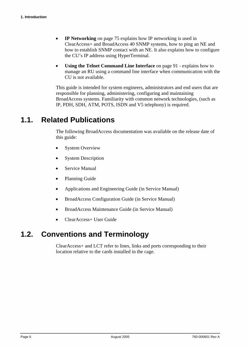
The following figures, BroadAccess Standard Cage General View and Card Locations and BroadAccess Mini Cage General View and Card Locations show card types and their position in BroadAccess cages. The table Element Naming Conventions Used in the Graphical User Interface on page 8 explains the conventions used for each Element.
Figure 1. BroadAccess Standard Cage General View and Card Locations
1. Introduction
Page 8 August 2005
760-000601 Rev A
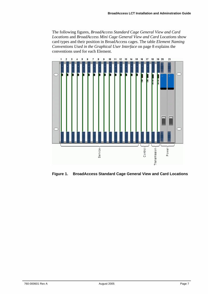
Figure 2. BroadAccess Mini Cage General View and Card Locations
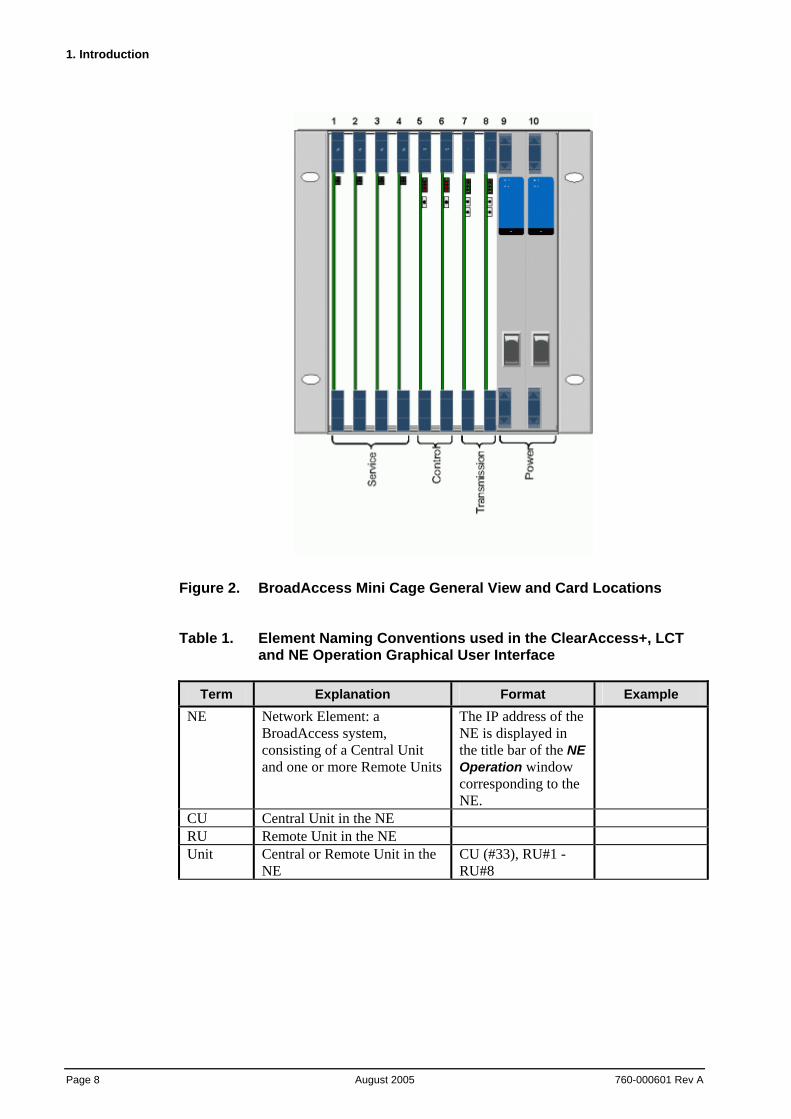
Table 1. Element Naming Conventions used in the ClearAccess+, LCT and NE Operation Graphical User Interface
Term Explanation Format Example
NE Network Element: a BroadAccess system, consisting of a Central Unit and one or more Remote Units
The IP address of the NE is displayed in the title bar of the NE Operation window corresponding to the NE.
CU Central Unit in the NE RU Remote Unit in the NE Unit Central or Remote Unit in the
NE CU (#33), RU#1 - RU#8
BroadAccess LCT Installation and Adminstration Guide
760-000601 Rev A August 2005
Page 9
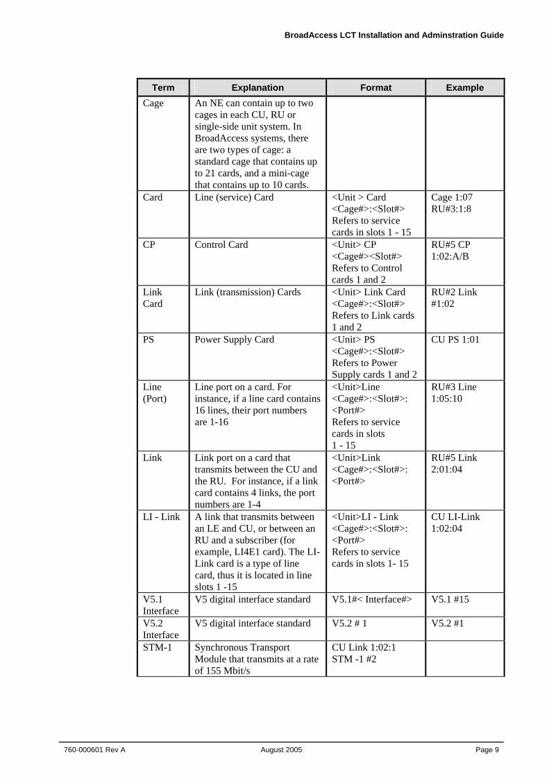
Term Explanation Format Example Cage An NE can contain up to two
cages in each CU, RU or single-side unit system. In BroadAccess systems, there are two types of cage: a standard cage that contains up to 21 cards, and a mini-cage that contains up to 10 cards.
Card Line (service) Card <Unit > Card <Cage#>:<Slot#> Refers to service cards in slots 1 - 15
Cage 1:07 RU#3:1:8
CP Control Card <Unit> CP <Cage#><Slot#> Refers to Control cards 1 and 2
RU#5 CP 1:02:A/B
Link Card
Link (transmission) Cards <Unit> Link Card <Cage#>:<Slot#> Refers to Link cards 1 and 2
RU#2 Link #1:02
PS Power Supply Card <Unit> PS <Cage#>:<Slot#> Refers to Power Supply cards 1 and 2
CU PS 1:01
Line (Port)
Line port on a card. For instance, if a line card contains 16 lines, their port numbers are 1-16
<Unit>Line <Cage#>:<Slot#>: <Port#> Refers to service cards in slots 1 - 15
RU#3 Line 1:05:10
Link Link port on a card that transmits between the CU and the RU. For instance, if a link card contains 4 links, the port numbers are 1-4
<Unit>Link <Cage#>:<Slot#>: <Port#>
RU#5 Link 2:01:04
LI - Link A link that transmits between an LE and CU, or between an RU and a subscriber (for example, LI4E1 card). The LI-Link card is a type of line card, thus it is located in line slots 1 -15
<Unit>LI - Link <Cage#>:<Slot#>: <Port#> Refers to service cards in slots 1- 15
CU LI-Link 1:02:04
V5.1 Interface
V5 digital interface standard V5.1#< Interface#> V5.1 #15
V5.2 Interface
V5 digital interface standard V5.2 # 1 V5.2 #1
STM-1 Synchronous Transport Module that transmits at a rate of 155 Mbit/s
CU Link 1:02:1 STM -1 #2
1. Introduction
Page 10 August 2005
760-000601 Rev A
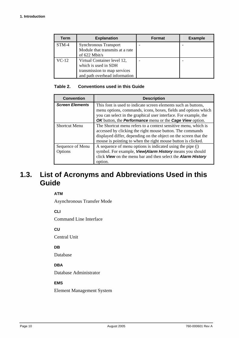
Term Explanation Format Example STM-4 Synchronous Transport
Module that transmits at a rate of 622 Mbit/s
- -
VC-12 Virtual Container level 12, which is used in SDH transmission to map services and path overhead information
- -
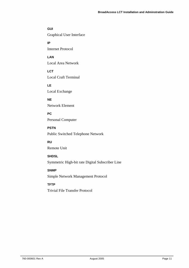
Table 2. Conventions used in this Guide
Convention Description Screen Elements This font is used to indicate screen elements such as buttons,
menu options, commands, icons, boxes, fields and options which you can select in the graphical user interface. For example, the OK button, the Performance menu or the Cage View option.
Shortcut Menu The Shortcut menu refers to a context sensitive menu, which is accessed by clicking the right mouse button. The commands displayed differ, depending on the object on the screen that the mouse is pointing to when the right mouse button is clicked.
Sequence of Menu Options
A sequence of menu options is indicated using the pipe (|) symbol. For example, View|Alarm History means you should click View on the menu bar and then select the Alarm History option.
1.3. List of Acronyms and Abbreviations Used in this Guide
ATM
Asynchronous Transfer Mode
CLI
Command Line Interface
CU
Central Unit
DB
Database
DBA
Database Administrator
EMS
Element Management System
BroadAccess LCT Installation and Adminstration Guide
760-000601 Rev A August 2005
Page 11
GUI
Graphical User Interface
IP
Internet Protocol
LAN
Local Area Network
LCT
Local Craft Terminal
LE
Local Exchange
NE
Network Element
PC
Personal Computer
PSTN
Public Switched Telephone Network
RU
Remote Unit
SHDSL
Symmetric High-bit rate Digital Subscriber Line
SNMP
Simple Network Management Protocol
TFTP
Trivial File Transfer Protocol

BroadAccess LCT Installation and Adminstration Guide
760-000601 Rev A August 2005
Page 1
2. BroadAccess System Overview BroadAccess is an Integrated Multiservice Access Platform (IMAP) which enables service providers to deliver any mix of narrowband and broadband services. With its flexible TDM/ATM/IP architecture and integrated SDH fiber optic transmission, BroadAccess is especially designed to provide an end-to-end solution in the access network.
The BroadAccess system is comprised of two main units: the Central Unit (CU) and one or more Remote Units (RUs). The CU is located at or near the local exchange, and the RUs are located at or near the subscribers' premises. The CU and RUs communicate with each other via digital links. Systems can be configured in a number of topologies such as point-to-point, star, ring and mixed ring and star. The system can also operate in a single-sided unit topology.
BroadAccess' main features include:
• Multi-service support - combined TDM/ATM/IP high-speed backplane supports diverse voice and data services.
• Flexibility - aggregated traffic can be transported over any integrated transmission device in various topologies (optionally protected) such as SDH ring, point-to-point and star. Additionally, traffic concentration, data grooming and multiplexing can be performed upon need.
• Modularity - plug-in cards enable simple expansion and upgrades without service interruption.
• Diverse connectivity - interface to TDM local exchange through V5.1/V5.2 or 2W connection; interface to NGN network through VoIP protocols; interface to ATM backbones through STM-1, and to IP backbones through Fast-Ethernet or Gigabit-Ethernet.
• Reliability - field-proven systems with a wide installed base in over 50 countries worldwide ensure reliable performance
• Optional redundancy - protects control, switching, transmission (including path protection in SDH rings) and power supply against failure.
• Compactness - ultra-compact solution with high density service cards.
• Various housing solutions - self-contained outdoor and indoor cabinets for clusters of 64 to 1920 subscribers.
• Future-proof - in order to support tomorrow's services such as VDSL, native ATM interfaces, Gigabit Ethernet and switched digital video (SDV), BroadAccess is enhanced with an ultra-fast backplane that enables aggregated traffic of multi-Gbit/s ATM/IP packets and TDM highways, as well as connecting all service and transmission slots.
2. BroadAccess System Overview
Page 2 August 2005
760-000601 Rev A
The system is comprised of a 19" card cage, 6U in height, into which all cards required for operation are inserted.
BroadAccess, along with other company products, can be managed by the ClearAccess+ EMS, which enables operators to effortlessly control hundreds of access systems.
A single BroadAccess system can also be managed locally or remotely by the BroadAccess' Windows-based Local Craft Terminal (LCT), providing full maintenance functionality via the same, familiar ClearAccess+ graphical user interface (GUI). When connected to the RU and communication between the CU and RU is not available, a limited range of management functions can be performed using a Telnet Command Line Interface (CLI) by connecting a PC to the RU.
For more information about the BroadAccess system, see the BroadAccess System Overview, BroadAccess System Description or BroadAccess Planning Guide.
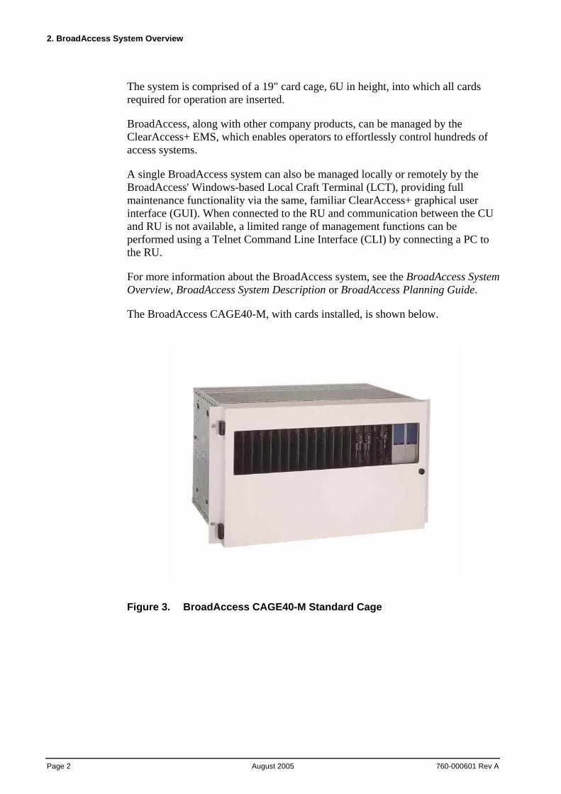
The BroadAccess CAGE40-M, with cards installed, is shown below.
Figure 3. BroadAccess CAGE40-M Standard Cage
BroadAccess LCT Installation and Adminstration Guide
760-000601 Rev A August 2005
Page 3
2.1. Local Craft Terminal Overview The LCT (Local Craft Terminal) lets you access and perform on-site operation and maintenance tasks on a BroadAccess system using direct connection via SNMP (Simple Network Management Protocol). It can be connected to either the BroadAccess CU or RU. The LCT runs on a computer using Windows 2000 operating systems. LCT is designed for on-site management tasks on a single BroadAccess system, and therefore its functionality is limited compared to the ClearAccess+ EMS. However, the LCT's Graphical User Interface (GUI) is very similar to the ClearAccess+ GUI, when applicable.
When communication is down between the CU and RU, the LCT computer, or any other computer where Windows is installed, can be connected to the RU and can perform a limited range of management functions, including display of alarm messages and inventory data, and software download and swap functions, using a Telnet Command Line Interface.

BroadAccess LCT Installation and Adminstration Guide
760-000601 Rev A August 2005
Page 5
3. System Requirements This section includes minimum hardware and software requirements for LCT.
3.1. Hardware Requirements Minimum hardware requirements for a computer running LCT are as follows:
• CPU: Pentium 3, 733 MHz
• Memory: 256 MB; 512 MB recommended
• Available free space on hard disk: 4 GB
• Network adapter (must support 10Base-T)
3.2. Software Requirements Software requirements for a computer running LCT are as follows:
• Microsoft Windows 2000 or XP
• Microsoft Windows Internet Explorer 6 or later
• Adobe Acrobat Reader 5 or later (optional, for viewing LCT documentation in PDF file format. It can be downloaded from Adobe's web site at www.Adobe.com)
Note: Microsoft Windows XP Service Pack 2 includes a firewall. You should disable or modify the permissions in the firewall, to allow LCT to function normally. Do one of the following: - Disable the Windows firewall - When the Windows firewall on your compter alerts you about use of ClearAccess.exe, MuLaunch.exe or NeConfig.exe, select the Always Allow option.

BroadAccess LCT Installation and Adminstration Guide
760-000601 Rev A August 2005
Page 7
4. Installing LCT LCT, Oracle Personal Edition and the Null modem driver installation files are provided on CD in the LCT Installation CD set.
Warning: Do not install LCT on a computer where ClearAccess+ is installed.
Warning: No other installations of Oracle should be present on your computer before you install LCT for the first time. Make sure that Oracle is not installed, and that your computer's registry does not contain any Oracle paths. If you are reinstalling the current LCT version, you do not need to uninstall and reinstall Oracle.
Warning: During installation of LCT, you will be asked to install Oracle. You will not be able to proceed with LCT installation unless you install Oracle. Installation of Oracle can take up to one hour.
Note: If you install LCT on a computer where LCT version 4.0 to 4.5.x is installed, the installation setup file detects it and uninstalls it automatically.
Note: Ensure that the regional settings on your computer are set to English - United States (you do this by opening Start|Settings|Control Panel|Regional Settings, and selecting the English - United States option).
To install LCT and Oracle:
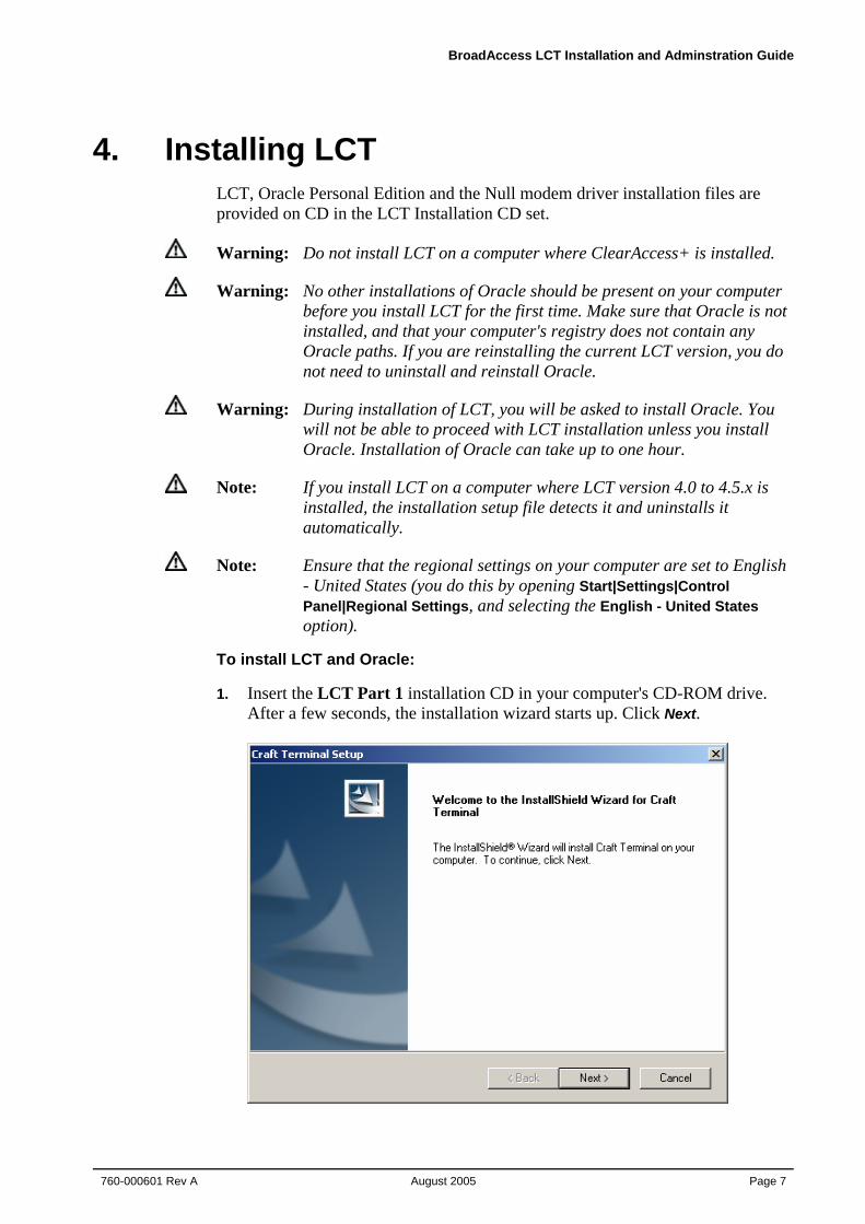
1. Insert the LCT Part 1 installation CD in your computer's CD-ROM drive. After a few seconds, the installation wizard starts up. Click Next.
4. Installing LCT
Page 8 August 2005
760-000601 Rev A
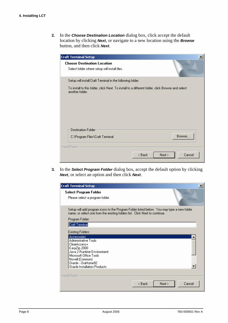
2. In the Choose Destination Location dialog box, click accept the default location by clicking Next, or navigate to a new location using the Browse button, and then click Next.
3. In the Select Program Folder dialog box, accept the default option by clicking Next, or select an option and then click Next.
BroadAccess LCT Installation and Adminstration Guide
760-000601 Rev A August 2005
Page 9
4. If Oracle is already installed on the computer, proceed to Step 9.
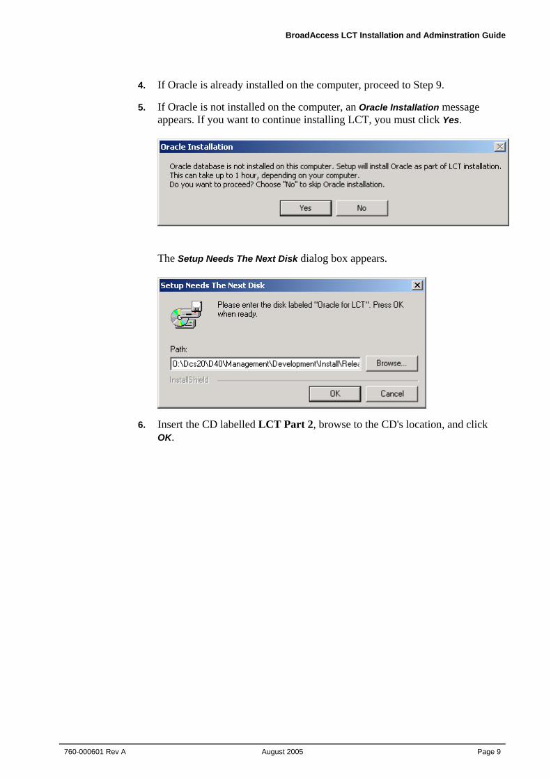
5. If Oracle is not installed on the computer, an Oracle Installation message appears. If you want to continue installing LCT, you must click Yes.
The Setup Needs The Next Disk dialog box appears.
6. Insert the CD labelled LCT Part 2, browse to the CD's location, and click OK.
4. Installing LCT
Page 10 August 2005
760-000601 Rev A
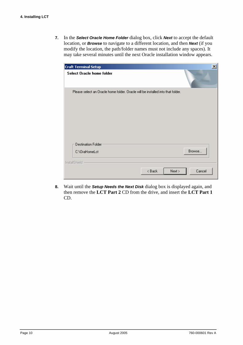
7. In the Select Oracle Home Folder dialog box, click Next to accept the default location, or Browse to navigate to a different location, and then Next (if you modify the location, the path/folder names must not include any spaces). It may take several minutes until the next Oracle installation window appears.
8. Wait until the Setup Needs the Next Disk dialog box is displayed again, and then remove the LCT Part 2 CD from the drive, and insert the LCT Part 1 CD.
BroadAccess LCT Installation and Adminstration Guide
760-000601 Rev A August 2005
Page 11
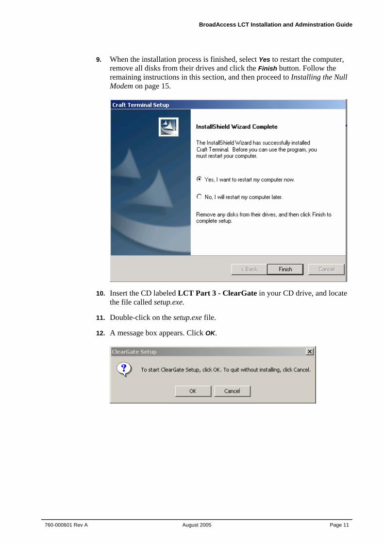
9. When the installation process is finished, select Yes to restart the computer, remove all disks from their drives and click the Finish button. Follow the remaining instructions in this section, and then proceed to Installing the Null Modem on page 15.
10. Insert the CD labeled LCT Part 3 - ClearGate in your CD drive, and locate the file called setup.exe.
11. Double-click on the setup.exe file.
12. A message box appears. Click OK.
4. Installing LCT
Page 12 August 2005
760-000601 Rev A
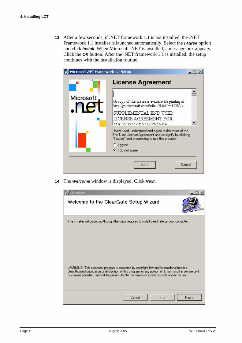
13. After a few seconds, if .NET framework 1.1 is not installed, the .NET Framework 1.1 installer is launched automatically. Select the I agree option and click Install. When Microsoft .NET is installed, a message box appears. Click the OK button. After the .NET framework 1.1 is installed, the setup continues with the installation routine.
14. The Welcome window is displayed. Click Next.
BroadAccess LCT Installation and Adminstration Guide
760-000601 Rev A August 2005
Page 13
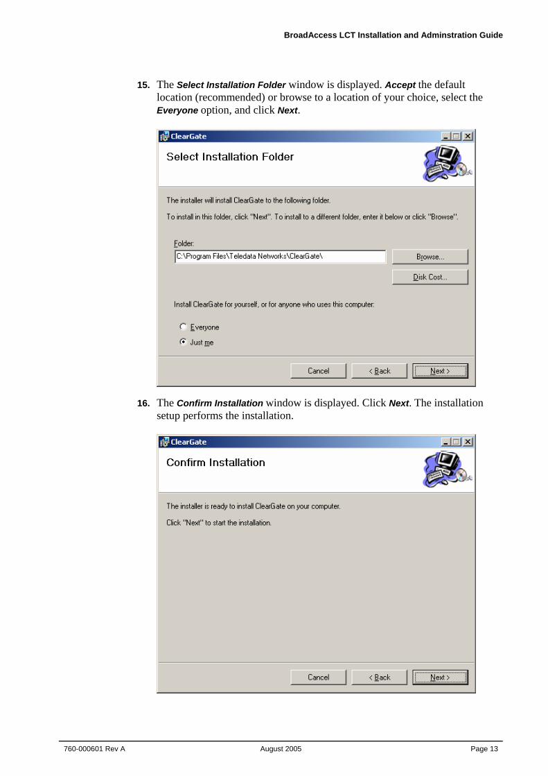
15. The Select Installation Folder window is displayed. Accept the default location (recommended) or browse to a location of your choice, select the Everyone option, and click Next.
16. The Confirm Installation window is displayed. Click Next. The installation setup performs the installation.
4. Installing LCT
Page 14 August 2005
760-000601 Rev A
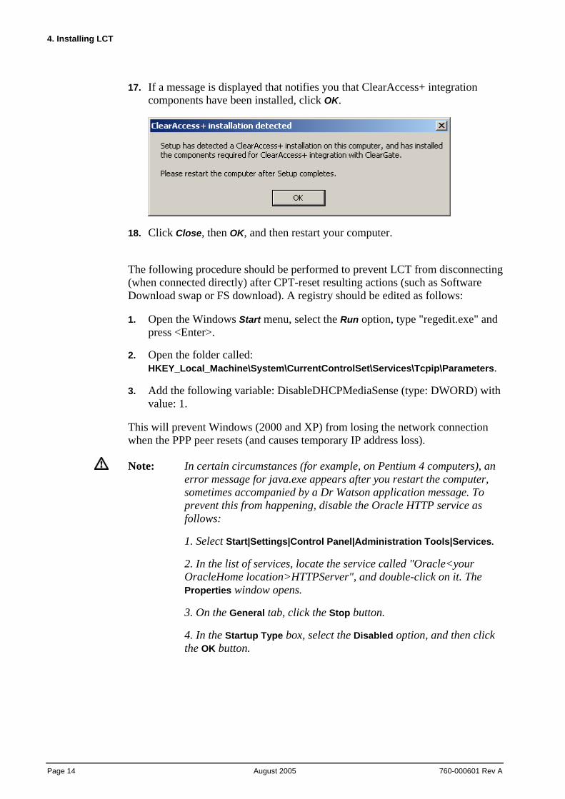
17. If a message is displayed that notifies you that ClearAccess+ integration components have been installed, click OK.
18. Click Close, then OK, and then restart your computer.
The following procedure should be performed to prevent LCT from disconnecting (when connected directly) after CPT-reset resulting actions (such as Software Download swap or FS download). A registry should be edited as follows:
1. Open the Windows Start menu, select the Run option, type "regedit.exe" and press <Enter>.
2. Open the folder called: HKEY_Local_Machine\System\CurrentControlSet\Services\Tcpip\Parameters.
3. Add the following variable: DisableDHCPMediaSense (type: DWORD) with value: 1.
This will prevent Windows (2000 and XP) from losing the network connection when the PPP peer resets (and causes temporary IP address loss).
Note: In certain circumstances (for example, on Pentium 4 computers), an error message for java.exe appears after you restart the computer, sometimes accompanied by a Dr Watson application message. To prevent this from happening, disable the Oracle HTTP service as follows:
1. Select Start|Settings|Control Panel|Administration Tools|Services.
2. In the list of services, locate the service called "Oracle<your OracleHome location>HTTPServer", and double-click on it. The Properties window opens.
3. On the General tab, click the Stop button.
4. In the Startup Type box, select the Disabled option, and then click the OK button.
BroadAccess LCT Installation and Adminstration Guide
760-000601 Rev A August 2005
Page 15
Warning: After installation is complete, the Administrator should change the passwords of default Users, or delete the default Users created during system installation. The default passwords for default Users are empty, which could result in a security breach.
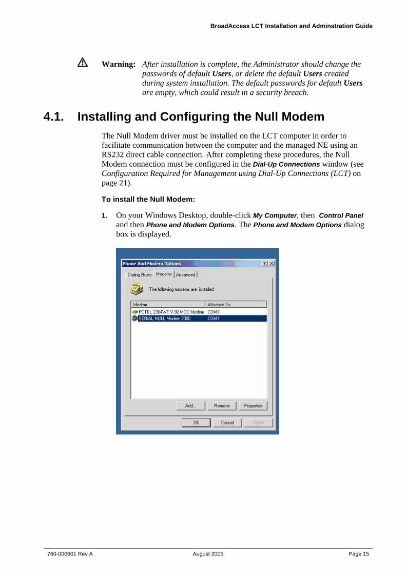
4.1. Installing and Configuring the Null Modem The Null Modem driver must be installed on the LCT computer in order to facilitate communication between the computer and the managed NE using an RS232 direct cable connection. After completing these procedures, the Null Modem connection must be configured in the Dial-Up Connections window (see Configuration Required for Management using Dial-Up Connections (LCT) on page 21).
To install the Null Modem:
1. On your Windows Desktop, double-click My Computer, then Control Panel and then Phone and Modem Options. The Phone and Modem Options dialog box is displayed.
4. Installing LCT
Page 16 August 2005
760-000601 Rev A
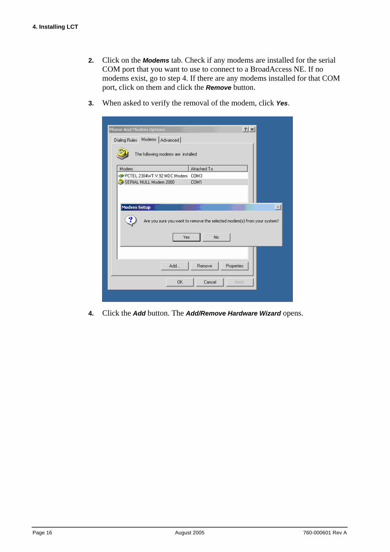
2. Click on the Modems tab. Check if any modems are installed for the serial COM port that you want to use to connect to a BroadAccess NE. If no modems exist, go to step 4. If there are any modems installed for that COM port, click on them and click the Remove button.
3. When asked to verify the removal of the modem, click Yes.
4. Click the Add button. The Add/Remove Hardware Wizard opens.
BroadAccess LCT Installation and Adminstration Guide
760-000601 Rev A August 2005
Page 17
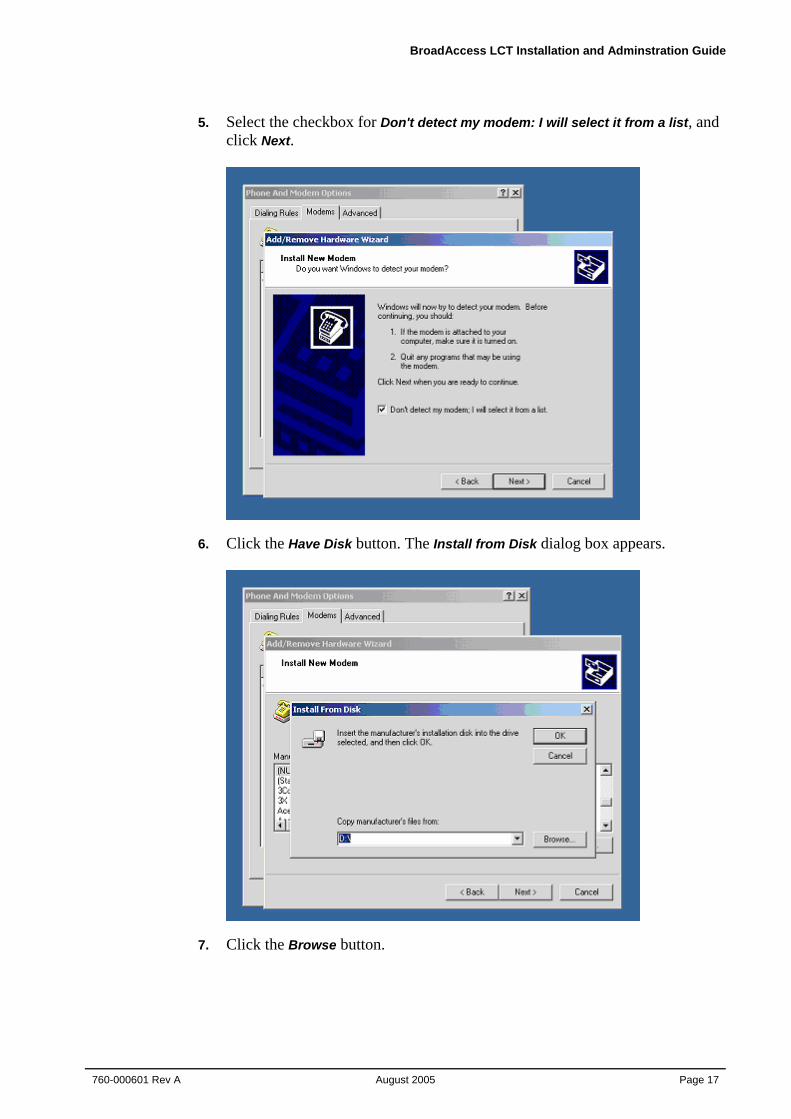
5. Select the checkbox for Don't detect my modem: I will select it from a list, and click Next.
6. Click the Have Disk button. The Install from Disk dialog box appears.
7. Click the Browse button.
4. Installing LCT
Page 18 August 2005
760-000601 Rev A
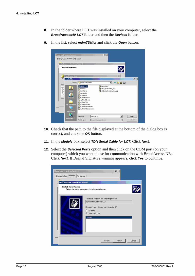
8. In the folder where LCT was installed on your computer, select the BroadAccess40-LCT folder and then the Devices folder.
9. In the list, select mdmTDNlct and click the Open button.
10. Check that the path to the file displayed at the bottom of the dialog box is correct, and click the OK button.
11. In the Models box, select TDN Serial Cable for LCT. Click Next.
12. Select the Selected Ports option and then click on the COM port (on your computer) which you want to use for communication with BroadAccess NEs. Click Next. If Digital Signature warning appears, click Yes to continue.
BroadAccess LCT Installation and Adminstration Guide
760-000601 Rev A August 2005
Page 19
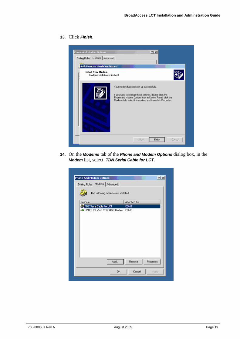
13. Click Finish.
14. On the Modems tab of the Phone and Modem Options dialog box, in the Modem list, select TDN Serial Cable for LCT.
4. Installing LCT
Page 20 August 2005
760-000601 Rev A
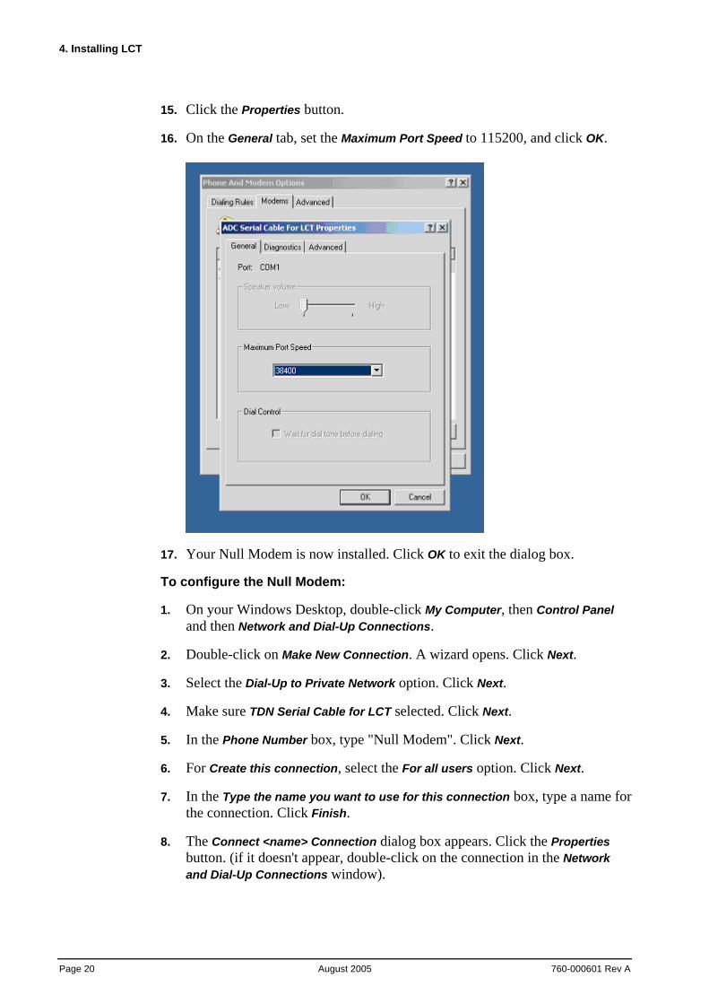
15. Click the Properties button.
16. On the General tab, set the Maximum Port Speed to 115200, and click OK.
17. Your Null Modem is now installed. Click OK to exit the dialog box.
To configure the Null Modem:
1. On your Windows Desktop, double-click My Computer, then Control Panel and then Network and Dial-Up Connections.
2. Double-click on Make New Connection. A wizard opens. Click Next.
3. Select the Dial-Up to Private Network option. Click Next.
4. Make sure TDN Serial Cable for LCT selected. Click Next.
5. In the Phone Number box, type "Null Modem". Click Next.
6. For Create this connection, select the For all users option. Click Next.
7. In the Type the name you want to use for this connection box, type a name for the connection. Click Finish.
8. The Connect <name> Connection dialog box appears. Click the Properties button. (if it doesn't appear, double-click on the connection in the Network and Dial-Up Connections window).
BroadAccess LCT Installation and Adminstration Guide
760-000601 Rev A August 2005
Page 21
9. On the General tab, clear the All devices call same number checkbox.
10. Click the Configure button. In the Modem Configuration window, clear all the options in the Hardware features box. Click OK.
11. On the Options tab, Display progress while connecting should be the only option selected. Redial attempts should be set to 0. Idle time should be set to Never. Click OK.
12. On the Security tab, select the Typical option. In the Validate my identity as follows box, select the Allow unsecured password option.
13. On the Networking tab, clear all options in the Components box, except for Internet Protocol TCP/IP.
14. Select Internet Protocol TCP/IP and click the Properties button. Select the following options: Obtain IP address automatically, Obtain DNS server automatically. Click the Advanced button.
15. Clear the options Use default gateway on remote network and Use IP header compression.
16. Click OK on all three dialog boxes to accept all the changes made.
17. From the LCT window's main menu, select the Configuration menu option, and then the Dial-Up Connection Groups option.
18. In the Dial-Up Connection Groups window, move the null modem connection that you configured to the Pool for User Initiated NE Operation box (see Configuration Required for Management using Dial-Up Connections (LCT) on page 21 for more information).
4.2. Configuration Required for Management using Dial-Up Connections
This section explains how to set up the NEs in your network for communication with the LCT computer over the PSTN, using dial-up connections. This configuration involves installing one or more modems at the LCT computer, and a modem at the NE (CU side), and connecting these modems to telephone lines. At the LCT side, you can install modems that are dedicated for each NE, or you can install a modem pool, from which modem connections will be assigned dynamically when communication with an NE is required. Following hardware installation, the following configurations need to be made at the NEs, and at the LCT:
• The NEs are configured for use with the modems, and these configuration activities are performed using LCT (using Ethernet connection).
• The NEs are assigned IP addresses, using LCT (using Ethernet connection).
4. Installing LCT
Page 22 August 2005
760-000601 Rev A
• The modems are configured on the LCT computer, using Microsoft Windows' Network and Dial-Up Connections features.
• Modem connections are configured using LCT.
• NEs are configured using LCT, including the type of modem connection (permanent/non-permanent) and the telephone number of the modem installed at the NE.
4.2.1. Hardware Setup
Modems must be installed both at the LCT and at the NEs (CU side). At the NE, the modem should be connected to the CU backplane using an RS-232 cable, and should be connected to the RS-232 port. The modems at both LCT side and at the NE side must be connected to telephone lines.
4.2.2. NE Preparations
At each NE using a dial-up connection, the following things need to be configured, using LCT:
1. The Modem Mode and Modem Initialization String must be configured, using the NE Operation window, IP Address Settings window, CU Interfaces tab. For more information, see Configuring IP Addresses on page 78.
2. The Default Gateway must be identical to the remote IP address. The local IP address must be on the same subnet as the remote IP address.
3. The Microsoft Windows Routing and Remote Access service must be started, and set to automatic. To do this, open the Windows Start menu, select the Settings option, and the Control Panel option. Double-click on the Administrative Tools icon, and then the Services icon. Double-click on the Routing and Remote Access service. Set the Startup Type to Automatic, and click the Start button. Click the OK button, and close the Services and Administrative Tools windows.
4. The Ethernet Interface subnet and the ATM Inband Interface subnet must be different from the subnet of the PC running the TFTP server (which is automatically installed during ClearAccess+ client installation).
5. Each NE must have a unique IP address.
BroadAccess LCT Installation and Adminstration Guide
760-000601 Rev A August 2005
Page 23
6. On the computer where the TFTP server is installed you have to make a new default gateway. To do this, open the Windows Start menu, select the Settings option, and the Control Panel option. Double-click on the Network and Dial-Up Connections icon, and then double-click on the Local Area Network icon. Click the Properties button. On the General tab, in the Components checked are used by this connection box, click on the Internet Protocol (TCP/IP) option, and click the Properties button. Click the Advanced button. On the IP Settings tab, in the Default Gateways box, click the Add button, and enter a new default gateway. The default gateway you add must be the IP address of the ClearAccess+ server. Click the Add button, and then the OK buttons in all the windows that were opened during this procedure.
4.2.3. LCT Computer Windows-Level Preparations
Communication using the PSTN occurs using a dial-up connection at the Windows level. Therefore, dial-up connections for each of the modems must be configured in Windows on the LCT computer, as follows:
1. From the Windows Start menu, select Settings and then Network and Dial-Up Connections. The Network and Dial-Up Connections window opens.
2. Double-click on the Make New Connection icon. The Network Connection wizard opens.
3. Click Next.
4. Select the Dial-Up to Private Network option, and click Next.
5. Select your modem from the list of devices displayed, and click Next.
6. Select the Use Dialing Rules checkbox, and click Next.
7. Select the For All Users option, and click Next.
8. Enter a name for this modem and click Finish.
9. Repeat steps 2 to 8 for the remaining modems you installed.
4.2.4. LCT Preparations
Using LCT, you configure the computer to use the dial-up connections that you configured for the modems in Windows. You can configure these connections to be used for permanent connections (each modem will be dedicated to a specific NE), for non-permanent connections (modems will be assigned to NEs dynamically from a modem pool), or for periodic polling (modems will be used dynamically for polling from a modem pool).
To configure modems to be used for permanent connections:
1. From the LCT main window's menu bar, select the Configuration option, and then the Dial-Up Connection Groups option. The Dial-Up Connection Groups window opens.
4. Installing LCT
Page 24 August 2005
760-000601 Rev A
2. Drag a modem connection from the left pane of the window (Available Dial-Up Connections) to the Permanent Connections to Specific NEs pane on the right side of the window.
3. Click the Apply Changes button.
To configure modems to be used for non-permanent connections:
1. From the LCT main window's menu bar, select the Configuration option, and then the Dial-Up Connection Groups option. The Dial-Up Connection Groups window opens.
2. Drag a modem connection from the left pane of the window (Available Dial-Up Connections) to the Pool for User Initiated NE Operation pane on the right side of the window.
3. Click the Apply Changes button.
To configure modems to be used for periodic polling:
1. From the LCT main window's menu bar, select the Configuration option, and then the Dial-Up Connection Groups option. The Dial-Up Connection Groups window opens.
2. Drag a modem connection from the left pane of the window (Available Dial-Up Connections) to the Pool for Periodic Polling pane on the right side of the window.
3. Click the Apply Changes button.
To test whether the modem is connected and operational:
In the Dial-Up Connection Groups window, select the modem you require and click the Test Entry button.
To return a modem connection to service after a modem was out-of-order:
In the Dial-Up Connection Groups window, select the modem you require and click the Back to Service button.
Once you have completed all the above procedures, you can configure NEs to use these modem connections, using the NE Properties window. For more information, see the procedure titled "To add an NE using a dial-up connection" in Creating and Configuring a BroadAccess 40 Network Element on page 41.
BroadAccess LCT Installation and Adminstration Guide
760-000601 Rev A August 2005
Page 25
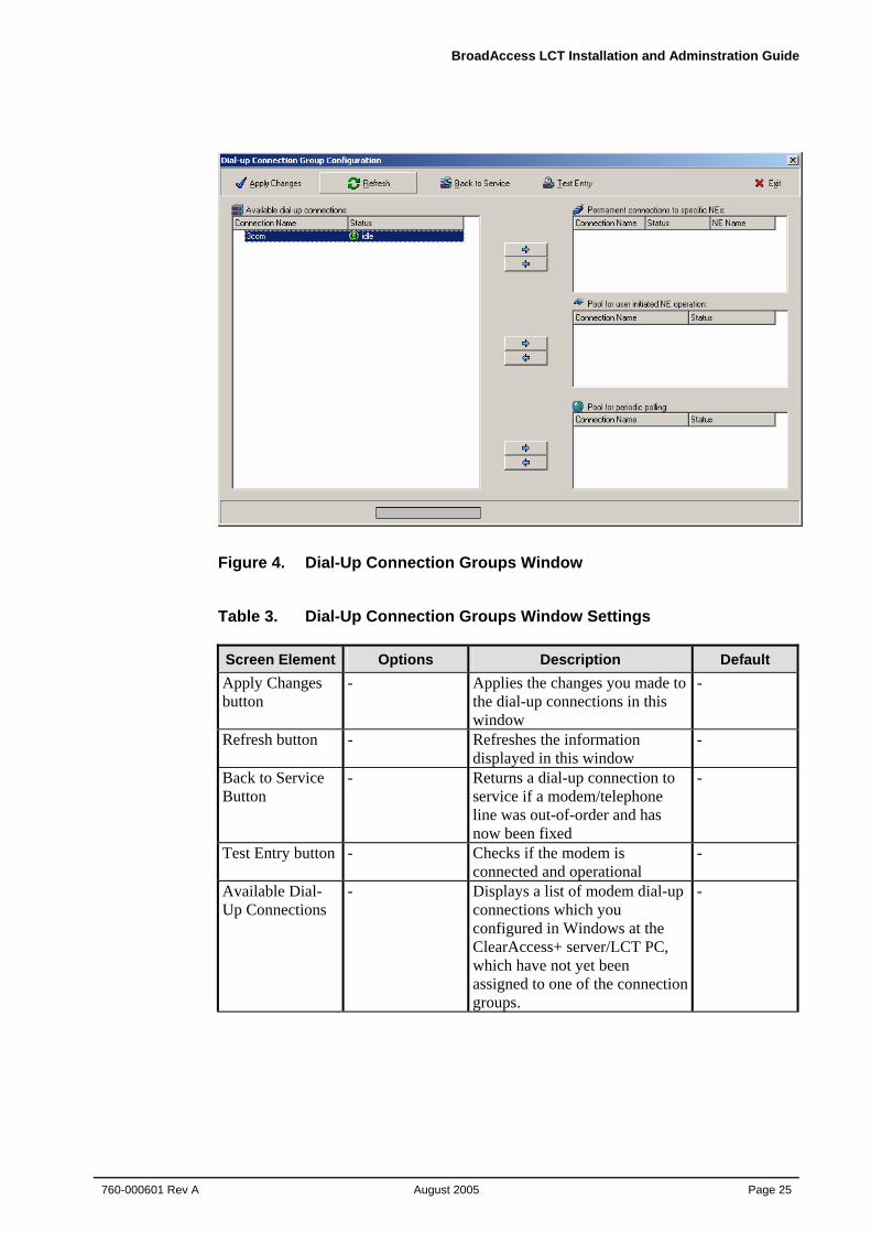
Figure 4. Dial-Up Connection Groups Window
Table 3. Dial-Up Connection Groups Window Settings Screen Element Options Description Default Apply Changes button
- Applies the changes you made to the dial-up connections in this window
-
Refresh button - Refreshes the information displayed in this window
-
Back to Service Button
- Returns a dial-up connection to service if a modem/telephone line was out-of-order and has now been fixed
-
Test Entry button - Checks if the modem is connected and operational
-
Available Dial-Up Connections
- Displays a list of modem dial-up connections which you configured in Windows at the ClearAccess+ server/LCT PC, which have not yet been assigned to one of the connection groups.
-
4. Installing LCT
Page 26 August 2005
760-000601 Rev A
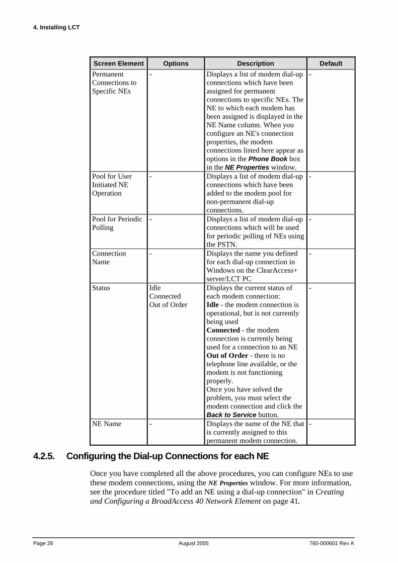
Screen Element Options Description Default Permanent Connections to Specific NEs
- Displays a list of modem dial-up connections which have been assigned for permanent connections to specific NEs. The NE to which each modem has been assigned is displayed in the NE Name column. When you configure an NE's connection properties, the modem connections listed here appear as options in the Phone Book box in the NE Properties window.
-
Pool for User Initiated NE Operation
- Displays a list of modem dial-up connections which have been added to the modem pool for non-permanent dial-up connections.
-
Pool for Periodic Polling
- Displays a list of modem dial-up connections which will be used for periodic polling of NEs using the PSTN.
-
Connection Name
- Displays the name you defined for each dial-up connection in Windows on the ClearAccess+ server/LCT PC
-
Status Idle Connected Out of Order
Displays the current status of each modem connection: Idle - the modem connection is operational, but is not currently being used Connected - the modem connection is currently being used for a connection to an NE Out of Order - there is no telephone line available, or the modem is not functioning properly. Once you have solved the problem, you must select the modem connection and click the Back to Service button.
-
NE Name - Displays the name of the NE that is currently assigned to this permanent modem connection.
-
4.2.5. Configuring the Dial-up Connections for each NE
Once you have completed all the above procedures, you can configure NEs to use these modem connections, using the NE Properties window. For more information, see the procedure titled "To add an NE using a dial-up connection" in Creating and Configuring a BroadAccess 40 Network Element on page 41.
BroadAccess LCT Installation and Adminstration Guide
760-000601 Rev A August 2005
Page 27
4.3. Upgrading LCT You can upgrade LCT from version 4.0x to version 6.0x, using the version 6.0x installation CDs. If you want to upgrade from version 3.x to 6.0x, you must first perform an upgrade from version 3.x to version 4.0x (using the version 4.0x installation CDs), and then perform the upgrade from version 4.0x to version 6.0x (using the version 6.0x installation CDs).
The LCT setup automatically detects the LCT installation, and uninstalls it. However, Oracle 8.1.6 (used with LCT version 3.x) is not automatically uninstalled. You must uninstall it manually, and then install LCT version 6.0.x.
Note: Ensure that LCT is closed before you upgrade it; including the LCT Start application that is visible on the Windows task bar.
Note: When upgrading LCT, the following Oracle passwords should be used, and the users should be assigned their original privileges: User Internal Password: Oracle User System Password: Manager
4.4. Uninstalling LCT The following procedure "cleans" your computer of all traces of LCT. For more information about uninstalling Oracle, see Uninstalling Oracle on page 28.
1. Use the Windows Add/Remove Programs feature, or run the LCT installation program (setup.exe file on the installation CD) of exactly the same file that was used to install LCT.
2. In the Welcome dialog box, select the Remove option, and click Next.
3. A Confirm Uninstall message appears, requesting you to confirm that you want to uninstall LCT. Click OK.
4. If a message appears saying that the file is read-only, click Yes.
5. If a message appears saying that the file is locked or in use, click Ignore.
6. Using the Windows My Computer feature, navigate to the LCT folder where the LCT was installed on your computer, and delete it.
7. Using the Windows My Computer feature, navigate to the folder called C:\Program Files\Common Files\CA Shared. Delete the CA Shared folder.
8. Open the Windows Start menu, select the Run option, type "regedit.exe" and press <Enter>.
9. Open the folder called HKEY_Local_Machine\Software\TDN\ClearAccess*. Delete the ClearAccess folder.
4. Installing LCT
Page 28 August 2005
760-000601 Rev A
10. Open the folder called HKEY_Current_User\Software\TDN\ClearAccess*. Delete the ClearAccess folder.
11. Open the Windows Control Panel, then open the System folder, click on the Advanced tab and then click on the Environment Variables button. In the Environment Variables dialog box, scroll to the Path row, and edit it to remove the path deleted in Step 7.
12. Restart the computer.
4.5. Uninstalling Oracle Removing or uninstalling Oracle software from a Windows 2000 or XP operating system requires several steps to completely creating a "clean" machine. This section explains what must be done to remove all Oracle software from the system.
Warning: Do not follow these instructions to uninstall Oracle 8i, if you have already installed Oracle 9i on the same computer. In such cases, you should follow the procedures described in Removing a Single Oracle Home on page 31.
Warning: Be careful, because these steps remove all Oracle software, Oracle services, and Oracle registry entries from the system. Any database files in the subdirectories under ORACLE_BASE\ORADATA\ are also removed. Oracle network configuration files, user-written scripts and other user generated files saved in Oracle_Base directories will also be removed. Therefore, it is advisable that you first perform a backup, if required, of certain files like: SQL*Nnet configuration files Database files Self-written scripts that are stored under the Oracle home directory, etc.
Warning: The following procedures require the editing of the Windows registry, which is a potentially dangerous operation. Exercise extreme caution when removing registry entries. Removing incorrect entries can severely compromise your computer. There is no undo option in the Registry Editor.
To uninstall Oracle:
1. Ensure that you have uninstalled LCT/ClearAccess+ before you uninstall Oracle.
2. Ensure that you are logged in as a user with Administrator privileges.
BroadAccess LCT Installation and Adminstration Guide
760-000601 Rev A August 2005
Page 29
3. Stop all Oracle-related services and all Oracle programs. You stop services by right-clicking on the My Computer icon on the Windows desktop, and selecting Manage|Services and Applications|Services. If any services that include "Oracle" in their names are running, select each one in turn and click Stop. When finished, close the Services window and the Control Panel/Computer Management window.
4. Start the registry editor: select Start|Run, type "regedit" and press <Enter>.
If the Oracle Universal Installer (OUI) was used, go to HKEY_LOCAL_MACHINE\Software\Oracle and write down the value of the INST_LOC variable. This shows you where the OUI software is installed. This can then be used to remove the OUI from the machine afterwards. Delete this Oracle key.
Go to HKEY_LOCAL_MACHINE\Software\ODBC, expand the subkeys and remove all the keys under this one that are related to Oracle ODBC Driver.
Go to HKEY_LOCAL_MACHINE\SYSTEM\CurrentControlSet\Services and remove the services starting with 'Oracle' (database related) and the ones that start with 'OraWeb' (Oracle Application Server related).
Go to HKEY_LOCAL_MACHINE\SYSTEM\CurrentControlSet\Services\EventLog\...\Application and remove all keys under her that begin with ORACLE.
Go to HKEY_LOCAL_MACHINE\Software\Microsoft\Windows\CurrentVersion\...\Uninstall and remove any entries related to Oracle.
Go to HKEY_CLASSES_ROOT, remove all keys that begin with Ora or ORCL (e.g. Oracle..., ORADC.., ORAMMC..., OraOLE..., OraPerf..., and ORCL...).
Go to HKEY_LOCAL_MACHINE\SOFTWARE\Classes, and remove all keys that begin with Ora or ORCL (e.g. Oracle..., ORADC.., ORAMMC..., OraOLE..., OraPerf..., and ORCL...).
Go to HKEY_CURRENT_USER\Software\Oracle and delete this ORACLE key.
Go to HKEY_USERS\Software\Oracle and delete this ORACLE key.
Close the registry editor.
5. Open the Start menu, select the Settings option, then the Control Panel option. Double-click on the System icon, click on the Advanced tab, and then on Environment variables.
4. Installing LCT
Page 30 August 2005
760-000601 Rev A
6. At System Variables click on the variable Path in order to modify the value. For example, you may see a path similar to this one: C:\ORACLE\ORA81\BIN;C:\PROGRAM FILES\ORACLE\JRE\1.1.7\BIN
7. If an %ORACLE_HOME% was installed, remove this %ORACLE_HOME%\BIN path.
8. If JRE was installed by Oracle, remove the JRE path.
9. If there is a CLASSPATH variable under System Variables, first make note of the path defined, then delete it. This variable can be added back at a later date if needed.
10. Check if there are any other Oracle variables set in "System Variables", ORACLE_HOME, ORACLE_SID, TNS_ADMIN, JSERV or WV_GATEWAY_CFG. If these exist, delete them as well.
11. Click on Apply and OK.
12. Close the Control Panel window.
13. Open the Start menu, select the following options: Programs|Accessories|Windows Explorer.
14. Go to %SystemDrive%\DOCUMENTS AND SETTINGS\ALL USERS\START MENU\PROGRAMS
Note 1: <http://metalink.oracle.com/metalink/plsql/ml2_documents.showDocument?p_id=1&p_database_id=NOT> These locations depend on whether the OS was upgraded from NT, or this was a fresh install of 2000/XP.
Note 2: <http://metalink.oracle.com/metalink/plsql/ml2_documents.showDocument?p_id=2&p_database_id=NOT> To locate your System Drive, type in DOS-box: echo %SystemDrive% and delete the following icons: Oracle Installation Products PRODUCT_NAME - HOME_NAME e.g. Oracle for Windows NT - Dev6i Oracle Reports 6i - Dev6i Oracle Olap Client 2.2 - Dev6i Oracle9i Lite Oracle - OraHome92
15. Go to %SystemDrive%\Program Files\Oracle or the location of INST_LOC as noted earlier in step 4 and delete this directory.
Note: In order to successfully delete all files, you may have to reboot your computer first, in order to clear Operating System locks on those files.
BroadAccess LCT Installation and Adminstration Guide
760-000601 Rev A August 2005
Page 31
16. Go to the temporary directory and delete all files and directories in here (see note in step 15) %SystemDrive%\Documents and Settings\<username>\Local Settings\Temp\
17. Go to the drive where the Oracle software is installed on your computer and delete all ORACLE_BASE directories on your hard drive (see note in step 15).
18. Close the Windows Explorer.
19. Right click on the Windows Recycle Bin and select the Empty Recycle Bin option.
20. Reboot your computer.
21. Optionally: run the System Defragmenter utility: from Control Panel, select Administrative Tools|Computer Management. Expand the Storage node, then select Disk Defragmenter. Highlight each virtual drive, in turn, and click Defragment. Reboot your computer when defragmentation is finished.
4.5.1. Removing a Single Oracle Home
This section describes how to manually remove all traces of an ORACLE_HOME on Microsoft Windows 2000/XP and how to manually remove Oracle components (e.g.: Oracle Server (RDBMS), iAS, OEM, client installations, etc.) and services from your computer for a specific ORACLE_HOME with the traces of the ORACLE_HOME itself. This section applies to multiple ORACLE_HOME installations.
These instructions are intended for DBAs for the Microsoft Windows (2000/XP) platform. This article only applies to Oracle products that are installed using Oracle Installer (ORAINST.EXE) or Oracle Universal Installer (OUI). For example the following products are not installed using Oracle installers so they are out of the scope of these procedures:
• JDeveloper
• JInitiator
• 9iFS File Sync
Warning: These procedures will also remove Oracle network configuration files, in a specific ORACLE_HOME.
Warning: If there are user written scripts and any other user generated files in the ORACLE_HOME they will be deleted.
Warning: Exercise extreme care when removing registry entries. Removing incorrect entries can severely compromise your computer.
4. Installing LCT
Page 32 August 2005
760-000601 Rev A
To remove traces of an ORACLE_HOME from a computer running Windows 2000/XP:
1. Ensure you are logged in as a user with Administrator privileges.
2. Stop all Oracle services related to the ORACLE_HOME (if any are running). You stop services by right-clicking on the My Computer icon on the Windows desktop, and selecting Manage|Services and Applications|Services. If any services that running on the Oracle_Home have the status Started, select each one in turn and click Stop. To determine which services to stop, check "Path to Executable" to see the directory where the executable for the service is located. When finished, close the Services window and the Control Panel/Computer Management window.
3. If the products in the ORACLE_HOME to be deleted are installed using the Oracle Universal Installer:
Start the Oracle Universal Installer (if it is not installed on your machine you can use the CD that you have used to install the products)
Click Deinstall Products
In the new dialog, expand the ORACLE_HOME to be deleted.
Check the product(s)
Click Remove.
Note: After completing the deinstallation of all products in an ORACLE_HOME, you will not see it in the Installed Products window. But keep in mind that the ORACLE_HOME is registered to the inventory and cannot be deregistered. Actually this does not have any harmful effect. The only effect is that you will see the ORACLE_HOME when you are performing a new installation using OUI, at the File Locations screen, the Destination selections and you cannot change the Name of an existing ORACLE_HOME.
1. If the products in the ORACLE_HOME to be deleted are installed using the Oracle Installer. (Developer 6i or before, 806_HOME of iAS, Discoverer, RDBMS Server 8.0 or earlier, etc.)
Start Oracle Installer (ORAINST.EXE) installed in the ORACLE_HOME to be deleted. (If you run the Installer from a product CD, be sure to select the ORACLE_HOME to be removed)
Select all items on the right-handside except the Oracle Installer.
Click Remove.
BroadAccess LCT Installation and Adminstration Guide
760-000601 Rev A August 2005
Page 33
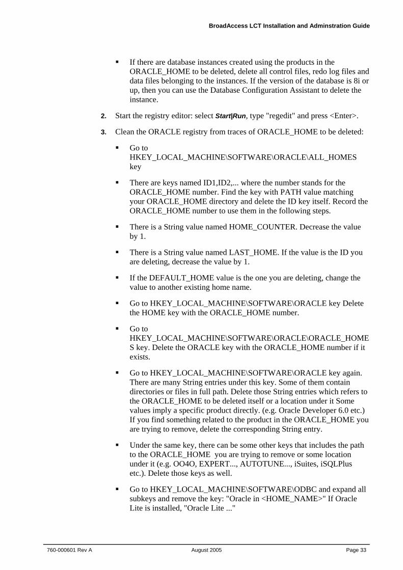
If there are database instances created using the products in the ORACLE_HOME to be deleted, delete all control files, redo log files and data files belonging to the instances. If the version of the database is 8i or up, then you can use the Database Configuration Assistant to delete the instance.
2. Start the registry editor: select Start|Run, type "regedit" and press <Enter>.
3. Clean the ORACLE registry from traces of ORACLE_HOME to be deleted:
Go to HKEY_LOCAL_MACHINE\SOFTWARE\ORACLE\ALL_HOMES key
There are keys named ID1,ID2,... where the number stands for the ORACLE_HOME number. Find the key with PATH value matching your ORACLE_HOME directory and delete the ID key itself. Record the ORACLE_HOME number to use them in the following steps.
There is a String value named HOME_COUNTER. Decrease the value by 1.
There is a String value named LAST_HOME. If the value is the ID you are deleting, decrease the value by 1.
If the DEFAULT_HOME value is the one you are deleting, change the value to another existing home name.
Go to HKEY_LOCAL_MACHINE\SOFTWARE\ORACLE key Delete the HOME key with the ORACLE_HOME number.
Go to HKEY_LOCAL_MACHINE\SOFTWARE\ORACLE\ORACLE_HOMES key. Delete the ORACLE key with the ORACLE_HOME number if it exists.
Go to HKEY_LOCAL_MACHINE\SOFTWARE\ORACLE key again. There are many String entries under this key. Some of them contain directories or files in full path. Delete those String entries which refers to the ORACLE_HOME to be deleted itself or a location under it Some values imply a specific product directly. (e.g. Oracle Developer 6.0 etc.) If you find something related to the product in the ORACLE_HOME you are trying to remove, delete the corresponding String entry.
Under the same key, there can be some other keys that includes the path to the ORACLE_HOME you are trying to remove or some location under it (e.g. OO4O, EXPERT..., AUTOTUNE..., iSuites, iSQLPlus etc.). Delete those keys as well.
Go to HKEY_LOCAL_MACHINE\SOFTWARE\ODBC and expand all subkeys and remove the key: "Oracle in <HOME_NAME>" If Oracle Lite is installed, "Oracle Lite ..."
4. Installing LCT
Page 34 August 2005
760-000601 Rev A
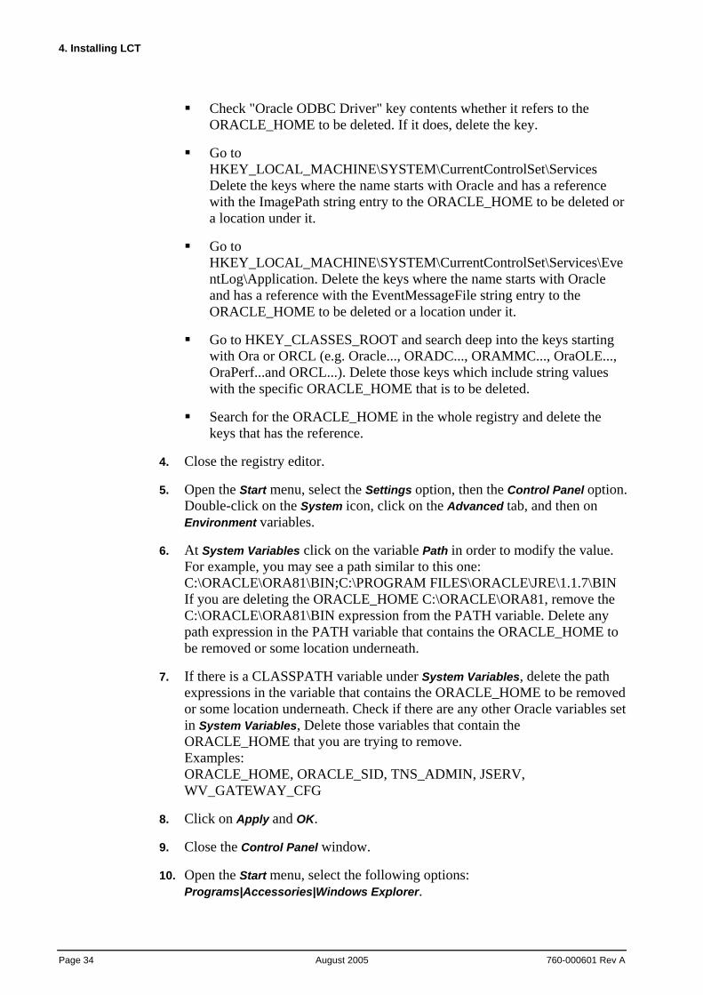
Check "Oracle ODBC Driver" key contents whether it refers to the ORACLE_HOME to be deleted. If it does, delete the key.
Go to HKEY_LOCAL_MACHINE\SYSTEM\CurrentControlSet\Services Delete the keys where the name starts with Oracle and has a reference with the ImagePath string entry to the ORACLE_HOME to be deleted or a location under it.
Go to HKEY_LOCAL_MACHINE\SYSTEM\CurrentControlSet\Services\EventLog\Application. Delete the keys where the name starts with Oracle and has a reference with the EventMessageFile string entry to the ORACLE_HOME to be deleted or a location under it.
Go to HKEY_CLASSES_ROOT and search deep into the keys starting with Ora or ORCL (e.g. Oracle..., ORADC..., ORAMMC..., OraOLE..., OraPerf...and ORCL...). Delete those keys which include string values with the specific ORACLE_HOME that is to be deleted.
Search for the ORACLE_HOME in the whole registry and delete the keys that has the reference.
4. Close the registry editor.
5. Open the Start menu, select the Settings option, then the Control Panel option. Double-click on the System icon, click on the Advanced tab, and then on Environment variables.
6. At System Variables click on the variable Path in order to modify the value. For example, you may see a path similar to this one: C:\ORACLE\ORA81\BIN;C:\PROGRAM FILES\ORACLE\JRE\1.1.7\BIN If you are deleting the ORACLE_HOME C:\ORACLE\ORA81, remove the C:\ORACLE\ORA81\BIN expression from the PATH variable. Delete any path expression in the PATH variable that contains the ORACLE_HOME to be removed or some location underneath.
7. If there is a CLASSPATH variable under System Variables, delete the path expressions in the variable that contains the ORACLE_HOME to be removed or some location underneath. Check if there are any other Oracle variables set in System Variables, Delete those variables that contain the ORACLE_HOME that you are trying to remove. Examples: ORACLE_HOME, ORACLE_SID, TNS_ADMIN, JSERV, WV_GATEWAY_CFG
8. Click on Apply and OK.
9. Close the Control Panel window.
10. Open the Start menu, select the following options: Programs|Accessories|Windows Explorer.
BroadAccess LCT Installation and Adminstration Guide
760-000601 Rev A August 2005
Page 35
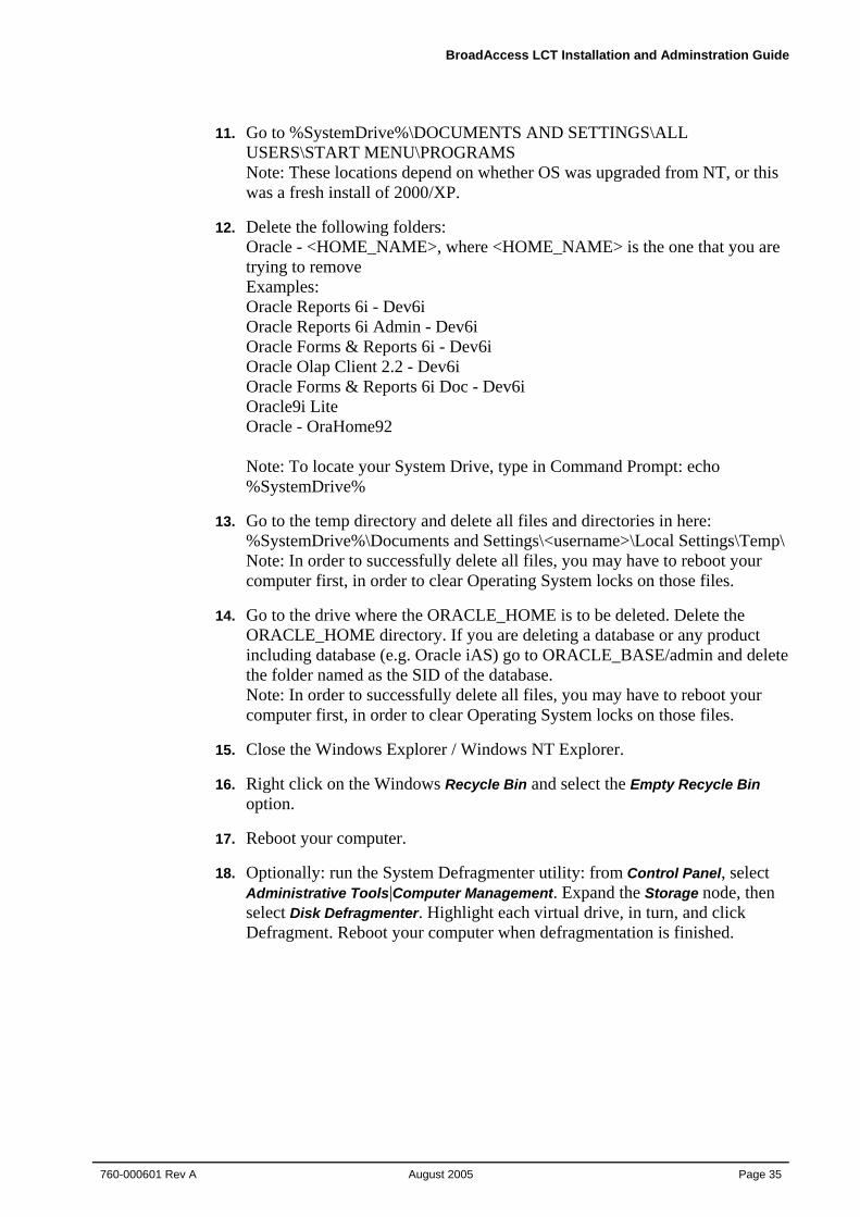
11. Go to %SystemDrive%\DOCUMENTS AND SETTINGS\ALL USERS\START MENU\PROGRAMS Note: These locations depend on whether OS was upgraded from NT, or this was a fresh install of 2000/XP.
12. Delete the following folders: Oracle - <HOME_NAME>, where <HOME_NAME> is the one that you are trying to remove Examples: Oracle Reports 6i - Dev6i Oracle Reports 6i Admin - Dev6i Oracle Forms & Reports 6i - Dev6i Oracle Olap Client 2.2 - Dev6i Oracle Forms & Reports 6i Doc - Dev6i Oracle9i Lite Oracle - OraHome92 Note: To locate your System Drive, type in Command Prompt: echo %SystemDrive%
13. Go to the temp directory and delete all files and directories in here: %SystemDrive%\Documents and Settings\<username>\Local Settings\Temp\ Note: In order to successfully delete all files, you may have to reboot your computer first, in order to clear Operating System locks on those files.
14. Go to the drive where the ORACLE_HOME is to be deleted. Delete the ORACLE_HOME directory. If you are deleting a database or any product including database (e.g. Oracle iAS) go to ORACLE_BASE/admin and delete the folder named as the SID of the database. Note: In order to successfully delete all files, you may have to reboot your computer first, in order to clear Operating System locks on those files.
15. Close the Windows Explorer / Windows NT Explorer.
16. Right click on the Windows Recycle Bin and select the Empty Recycle Bin option.
17. Reboot your computer.
18. Optionally: run the System Defragmenter utility: from Control Panel, select Administrative Tools|Computer Management. Expand the Storage node, then select Disk Defragmenter. Highlight each virtual drive, in turn, and click Defragment. Reboot your computer when defragmentation is finished.
4. Installing LCT
Page 36 August 2005
760-000601 Rev A
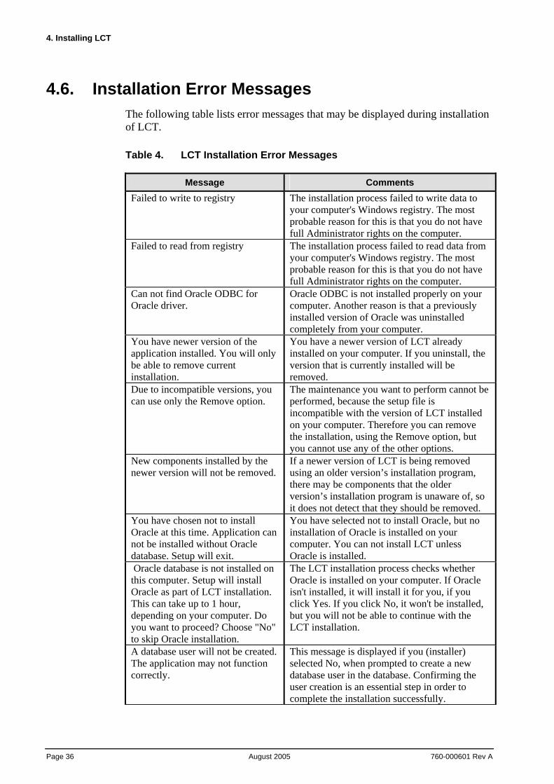
4.6. Installation Error Messages The following table lists error messages that may be displayed during installation of LCT.
Table 4. LCT Installation Error Messages
Message Comments Failed to write to registry The installation process failed to write data to
your computer's Windows registry. The most probable reason for this is that you do not have full Administrator rights on the computer.
Failed to read from registry The installation process failed to read data from your computer's Windows registry. The most probable reason for this is that you do not have full Administrator rights on the computer.
Can not find Oracle ODBC for Oracle driver.
Oracle ODBC is not installed properly on your computer. Another reason is that a previously installed version of Oracle was uninstalled completely from your computer.
You have newer version of the application installed. You will only be able to remove current installation.
You have a newer version of LCT already installed on your computer. If you uninstall, the version that is currently installed will be removed.
Due to incompatible versions, you can use only the Remove option.
The maintenance you want to perform cannot be performed, because the setup file is incompatible with the version of LCT installed on your computer. Therefore you can remove the installation, using the Remove option, but you cannot use any of the other options.
New components installed by the newer version will not be removed.
If a newer version of LCT is being removed using an older version’s installation program, there may be components that the older version’s installation program is unaware of, so it does not detect that they should be removed.
You have chosen not to install Oracle at this time. Application can not be installed without Oracle database. Setup will exit.
You have selected not to install Oracle, but no installation of Oracle is installed on your computer. You can not install LCT unless Oracle is installed.
Oracle database is not installed on this computer. Setup will install Oracle as part of LCT installation. This can take up to 1 hour, depending on your computer. Do you want to proceed? Choose "No" to skip Oracle installation.
The LCT installation process checks whether Oracle is installed on your computer. If Oracle isn't installed, it will install it for you, if you click Yes. If you click No, it won't be installed, but you will not be able to continue with the LCT installation.
A database user will not be created. The application may not function correctly.
This message is displayed if you (installer) selected No, when prompted to create a new database user in the database. Confirming the user creation is an essential step in order to complete the installation successfully.
BroadAccess LCT Installation and Adminstration Guide
760-000601 Rev A August 2005
Page 37
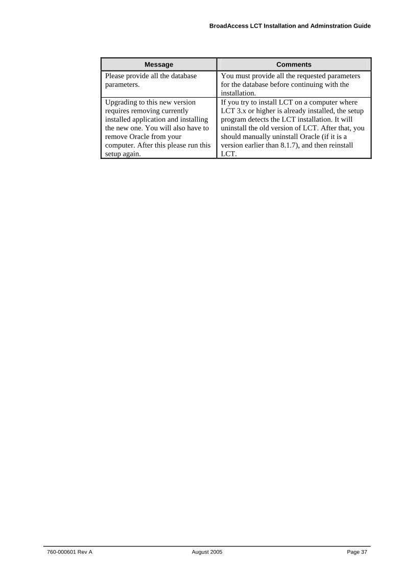
Message Comments Please provide all the database parameters.
You must provide all the requested parameters for the database before continuing with the installation.
Upgrading to this new version requires removing currently installed application and installing the new one. You will also have to remove Oracle from your computer. After this please run this setup again.
If you try to install LCT on a computer where LCT 3.x or higher is already installed, the setup program detects the LCT installation. It will uninstall the old version of LCT. After that, you should manually uninstall Oracle (if it is a version earlier than 8.1.7), and then reinstall LCT.

BroadAccess LCT Installation and Adminstration Guide
760-000601 Rev A August 2005
Page 39
5. Opening an LCT Session Before opening an LCT session, ensure that:
• The NE is connected to one of the following:
a LAN or WAN, using an Ethernet cable connected to the system backplane
a dial-up modem, using an RS232 cable connected to the system backplane
directly to the LCT computer, using an RS232 cable
• If a direct connection is being used, ensure that the Null Modem driver has been installed and configured on the LCT computer (for more information, see Installing and Configuring the Null Modem on page 15)
• If a dial-up connection is being used, ensure that the modem driver has been installed and configured on the LCT computer
• The CU and RUs have power switched on
• The local craft terminal software has been installed on your computer (see Installing LCT on page 7)
• You know your user name and password for logging in to LCT, and your LCT User user name and password for connecting to the NE (for more information, see Security Management on page 63)
Proceed as described in the following sections:
1. Logging on to the LCT on page 39
2. Creating and Configuring a BroadAccess 40 Network Element on page 41
5.1. Logging on and Connecting to the BroadAccess NE
The network administrator should be the first user to log in to LCT. After logging in to LCT, the network administrator should define a list of authorized users for loggin in to LCT ("Users") and for connecting to the NE ("LCT Users"), including a user name and password for himself or herself, as explained in Security Management on page 63.
Note: If you closed LCT and want to restart it, wait a few seconds, until the LCT icon at the bottom right corner of the screen disappears.
5. Opening an LCT Session
Page 40 August 2005
760-000601 Rev A
Note: Microsoft Windows XP Service Pack 2 includes a firewall. You should disable or modify the permissions in the firewall, to allow LCT to function normally. Do one of the following: - Disable the Windows firewall - When the Windows firewall on your compter alerts you about use of ClearAccess.exe, MuLaunch.exe or NeConfig.exe, select the Always Allow option.
To log in to the LCT:
1. Ensure that the LCT Start application is running (it should appear as one of the buttons on the Windows task bar). If it is not running, start it as follows: Click the Windows Start button and select the Programs option, then the Startup option and then the LCT Start option.
2. Click the Windows Start button and select the Programs option, then the LCT option, then the BroadAccess 40 LCT folder, and then the BroadAccess 40 LCT option. The BroadAccess 40 Local Craft Terminal (LCT) opens, and the Login dialog box is displayed.
3. In the Login dialog box, enter the following:
User Name - type your user name.
Password - type your password.
Server Address - read only.
4. Click OK. The LCT main window opens.
5. Click on the NE icon in the left pane of the LCT main window. If an NE icon has not been defined for the NE, refer to Creating and Configuring a BroadAccess 40 Network Element on page 41 (in the LCT Installation and Administration Guide/LCT Online Help system).
6. Select the Configuration menu option, and then the Connect option.
7. If you are connecting to an NE where no LCT Users have been defined, enter "admin" in the User Name box, and "BroadAccess40" in the Password box. If LCT Users have been defined, obtain your user name and password from your system administrator, and enter them. The LCT connects to the BroadAccess system. If any alarms exist in the system, they are displayed in the right pane of the main LCT window. You can perform configuration activities and view performance data by selecting Configuration and then NE Operation from the menu bar.
After three failed login attempts, the system will shut down. Wait five minutes before you try to login again.
BroadAccess LCT Installation and Adminstration Guide
760-000601 Rev A August 2005
Page 41
5.2. Creating and Configuring a BroadAccess 40 Network Element
If this is the first time you are connecting to this NE, or if an NE icon for the system is not displayed in the left pane of the LCT main window, you must define the NE as described in the following instructions. You will not be able to view alarms or perform any other management activities until you have defined the NE.
If you want to connect to an NE using a Dial-Up connection, you must set up modem definitions and dial-up connection configurations using an Ethernet connection first, and then set up the additional NE Properties required for dial-up connections. For more information, see Configuration Required for Management using Dial-Up Connections on page 21.
If you want to connect to an NE using a direct RS232 connection, you must install a null-modem driver and additional configurations first, and then set up the NE Properties required for direct connections. For more information, see Installing the Null Modem on page 15.
To create and configure a BroadAccess 40 Network Element (using a LAN/WAN connection):
1. From the menu bar, select the Configuration option, and the New Domain option. The Domain Properties dialog box appears.
2. Enter a name for the Domain in the Name field, and click OK. A Domain icon with the name you assigned to it appears in the left pane of the LCT main window.
3. Click the New Element button. The NE Properties dialog box appears.
4. On the General tab, enter a name for the NE in the Name field.
5. On the IP tab, enter an IP address in the IP Address field, as follows:
If the LCT is connected to the NE via the CU backplane, enter the External CU IP Address
If the LCT is connected to the NE via the RU backplane, enter the Internal CU IP Address
To add an NE using a dial-up connection:
Note: Before creating an NE using a PSTN connection, ensure that you have set up the required parameters and equipment, as explained in detail in Configuration Required for Management using Dial-Up Connections on page 21.
1. From the menu bar, select the Configuration option, and the New Domain option. The Domain Properties dialog box appears.
5. Opening an LCT Session
Page 42 August 2005
760-000601 Rev A
2. Enter a name for the Domain in the Name field, and click OK. A Domain icon with the name you assigned to it appears in the left pane of the LCT main window.
3. Click the New Element button. The NE Properties dialog box appears.
4. On the General tab, in the Name box, enter an NE name.
5. On the General tab, in the EMS to NE box, select the Dial-Up option.
6. On the General tab, select one of the following:
Permanent - lets you select a modem from the Phone Book entry box, via which a permanent dial-up connection will be established with the NE
Non-permanent - configures the system so that you can connect to the NE on-demand from a pool of modems, or for periodic polling operations
7. On the IP tab, enter the IP address of the NE in the IP Address box. Even when PSTN connections are used, this IP address is still required, and should be unique for each NE.
8. On the Telephone of NE tab, enter the telephone number to which the NE is connected. Note that any telephone number configured during Windows-level modem definitions are overridden by this telephone number.
9. Click the OK button. An NE icon with the name you assigned to the NE appears on the Network Tree in the main LCT window.
To add an NE using a direct RS232 cable connection:
Note: Before creating an NE using a direct connection, ensure that you have set up the required parameters and equipment, as explained in detail in Installing and Configuring the Null Modem on page 15.
1. From the menu bar, select the Configuration option, and the New Domain option. The Domain Properties dialog box appears.
2. Enter a name for the Domain in the Name field, and click OK. A Domain icon with the name you assigned to it appears in the left pane of the LCT main window.
3. Click the New Element button. The NE Properties dialog box appears.
4. On the General tab, in the Name box, enter an NE name.
5. On the General tab, in the EMS to NE box, select the Direct RS232 option.
6. On the IP tab, enter the PPP Interface local IP address of the NE in the IP Address box. Even when direct connections are used, this IP address is still required, and should be unique for each NE.
BroadAccess LCT Installation and Adminstration Guide
760-000601 Rev A August 2005
Page 43
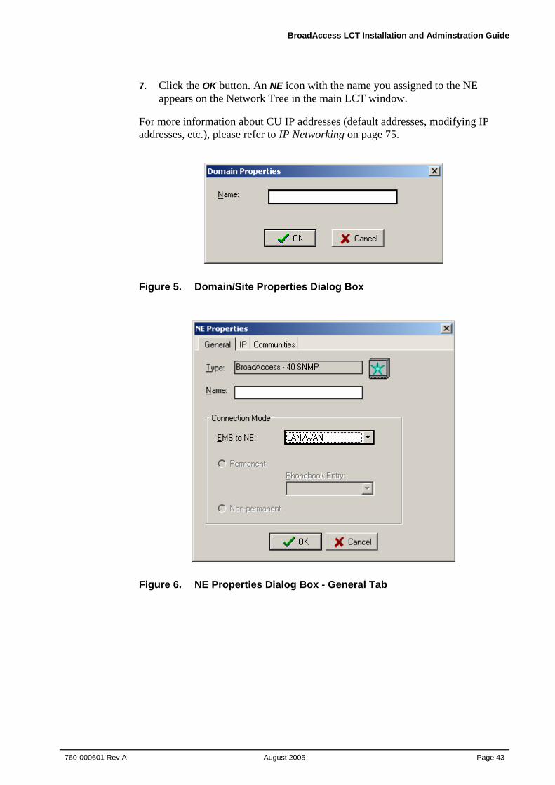
7. Click the OK button. An NE icon with the name you assigned to the NE appears on the Network Tree in the main LCT window.
For more information about CU IP addresses (default addresses, modifying IP addresses, etc.), please refer to IP Networking on page 75.
Figure 5. Domain/Site Properties Dialog Box
Figure 6. NE Properties Dialog Box - General Tab
5. Opening an LCT Session
Page 44 August 2005
760-000601 Rev A
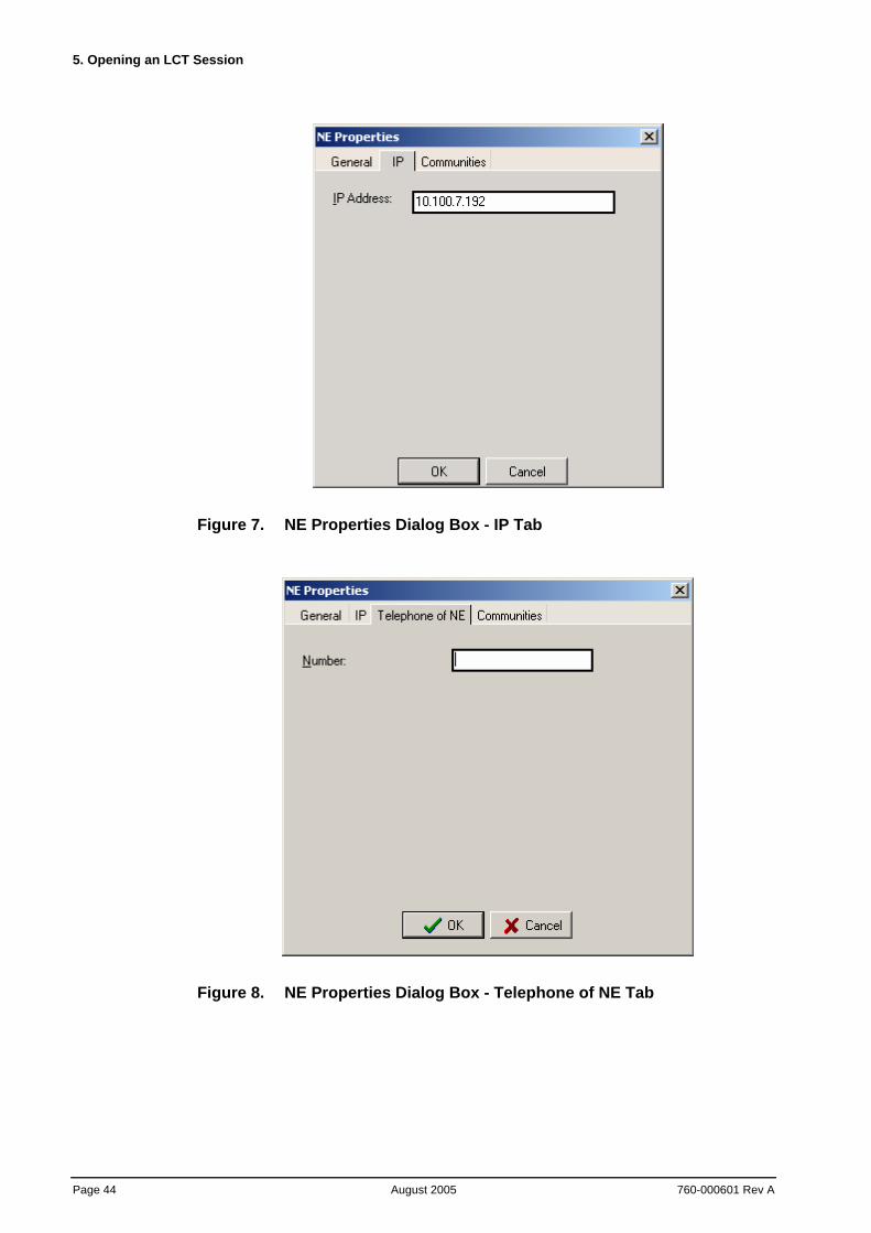
Figure 7. NE Properties Dialog Box - IP Tab
Figure 8. NE Properties Dialog Box - Telephone of NE Tab
BroadAccess LCT Installation and Adminstration Guide
760-000601 Rev A August 2005
Page 45
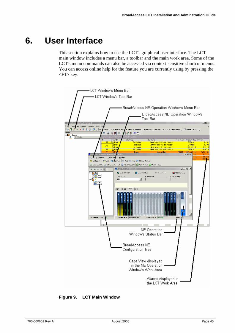
6. User Interface This section explains how to use the LCT's graphical user interface. The LCT main window includes a menu bar, a toolbar and the main work area. Some of the LCT's menu commands can also be accessed via context-sensitive shortcut menus. You can access online help for the feature you are currently using by pressing the <F1> key.
Figure 9. LCT Main Window
6. User Interface
Page 46 August 2005
760-000601 Rev A
6.1. LCT Work Area The following items can be displayed in the Work Area:
• Current alarms
• Alarm history
• Other windows opened from the menu bar, toolbar or shortcut menus
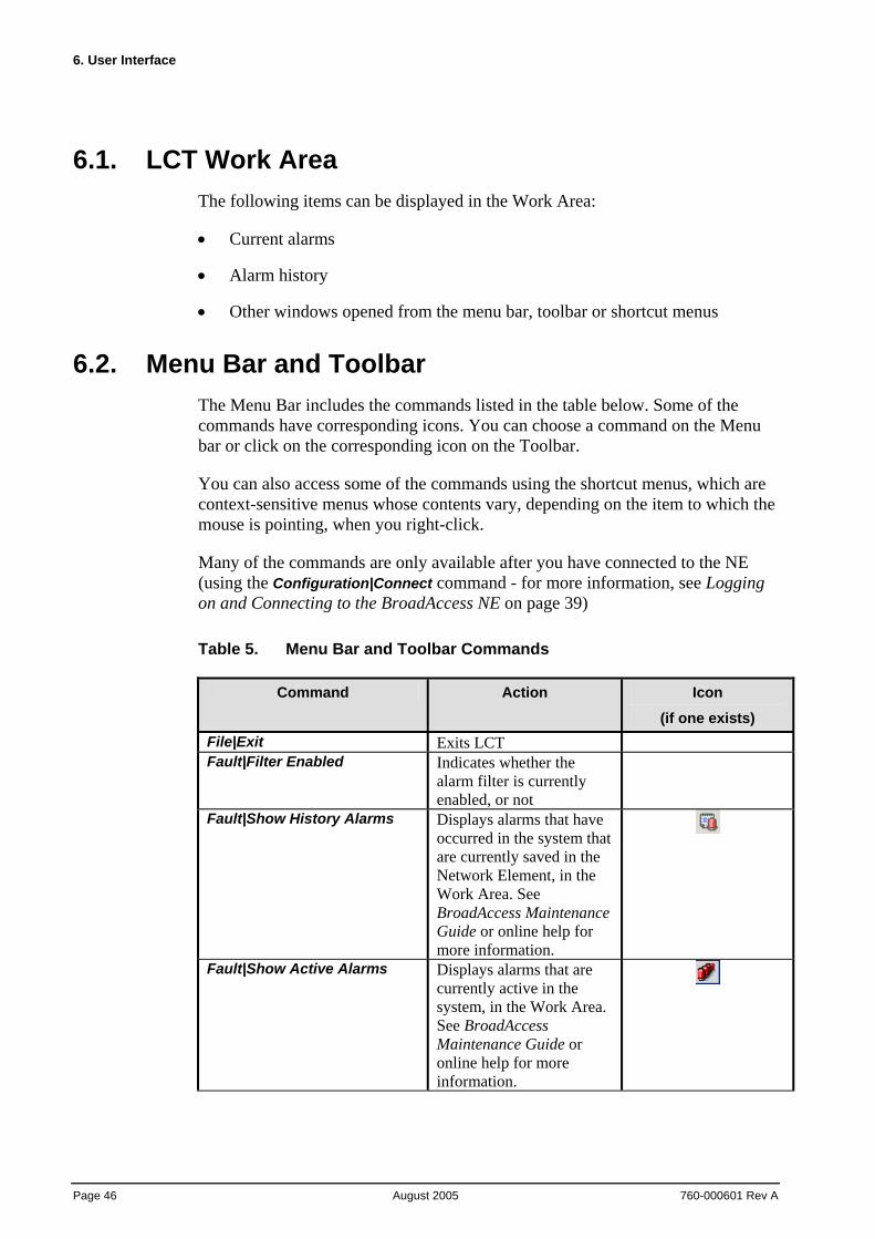
6.2. Menu Bar and Toolbar The Menu Bar includes the commands listed in the table below. Some of the commands have corresponding icons. You can choose a command on the Menu bar or click on the corresponding icon on the Toolbar.
You can also access some of the commands using the shortcut menus, which are context-sensitive menus whose contents vary, depending on the item to which the mouse is pointing, when you right-click.
Many of the commands are only available after you have connected to the NE (using the Configuration|Connect command - for more information, see Logging on and Connecting to the BroadAccess NE on page 39)
Table 5. Menu Bar and Toolbar Commands
Command Action Icon
(if one exists) File|Exit Exits LCT Fault|Filter Enabled Indicates whether the
alarm filter is currently enabled, or not
Fault|Show History Alarms Displays alarms that have occurred in the system that are currently saved in the Network Element, in the Work Area. See BroadAccess Maintenance Guide or online help for more information.
Fault|Show Active Alarms Displays alarms that are currently active in the system, in the Work Area. See BroadAccess Maintenance Guide or online help for more information.
BroadAccess LCT Installation and Adminstration Guide
760-000601 Rev A August 2005
Page 47
Command Action Icon
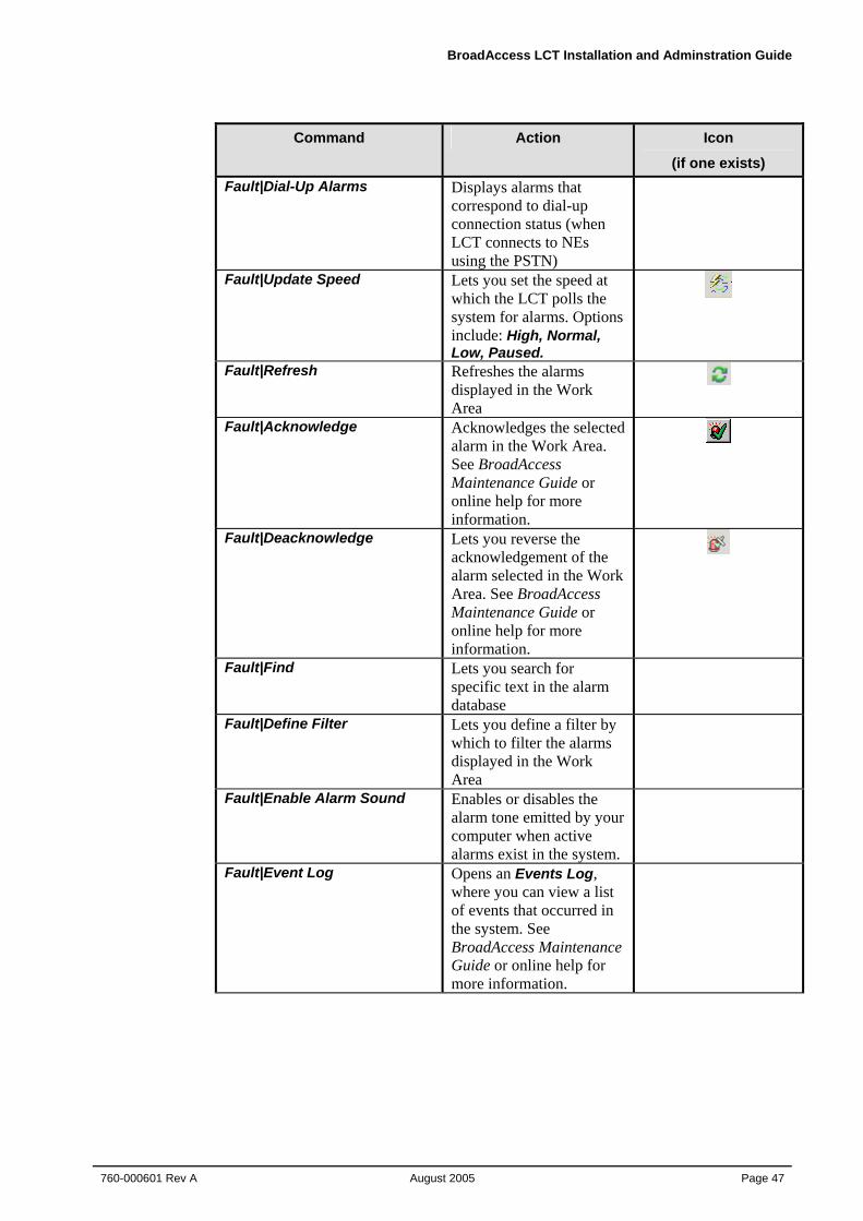
(if one exists) Fault|Dial-Up Alarms Displays alarms that
correspond to dial-up connection status (when LCT connects to NEs using the PSTN)
Fault|Update Speed Lets you set the speed at which the LCT polls the system for alarms. Options include: High, Normal, Low, Paused.
Fault|Refresh Refreshes the alarms displayed in the Work Area
Fault|Acknowledge Acknowledges the selected alarm in the Work Area. See BroadAccess Maintenance Guide or online help for more information.
Fault|Deacknowledge Lets you reverse the acknowledgement of the alarm selected in the Work Area. See BroadAccess Maintenance Guide or online help for more information.
Fault|Find Lets you search for specific text in the alarm database
Fault|Define Filter Lets you define a filter by which to filter the alarms displayed in the Work Area
Fault|Enable Alarm Sound Enables or disables the alarm tone emitted by your computer when active alarms exist in the system.
Fault|Event Log Opens an Events Log, where you can view a list of events that occurred in the system. See BroadAccess Maintenance Guide or online help for more information.
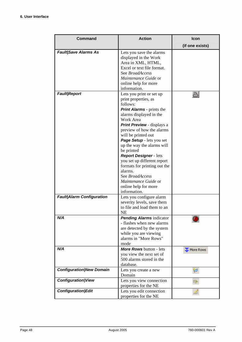
6. User Interface
Page 48 August 2005
760-000601 Rev A
Command Action Icon
(if one exists) Fault|Save Alarms As Lets you save the alarms
displayed in the Work Area in XML, HTML, Excel or text file format. See BroadAccess Maintenance Guide or online help for more information.
Fault|Report Lets you print or set up print properties, as follows: Print Alarms - prints the alarms displayed in the Work Area Print Preview - displays a preview of how the alarms will be printed out Page Setup - lets you set up the way the alarms will be printed Report Designer - lets you set up different report formats for printing out the alarms. See BroadAccess Maintenance Guide or online help for more information.
Fault|Alarm Configuration Lets you configure alarm severity levels, save them to file and load them to an NE
N/A Pending Alarms indicator - flashes when new alarms are detected by the system while you are viewing alarms in "More Rows" mode
N/A More Rows button - lets you view the next set of 500 alarms stored in the database.
Configuration|New Domain Lets you create a new Domain
Configuration|View Lets you view connection properties for the NE
Configuration|Edit Lets you edit connection properties for the NE
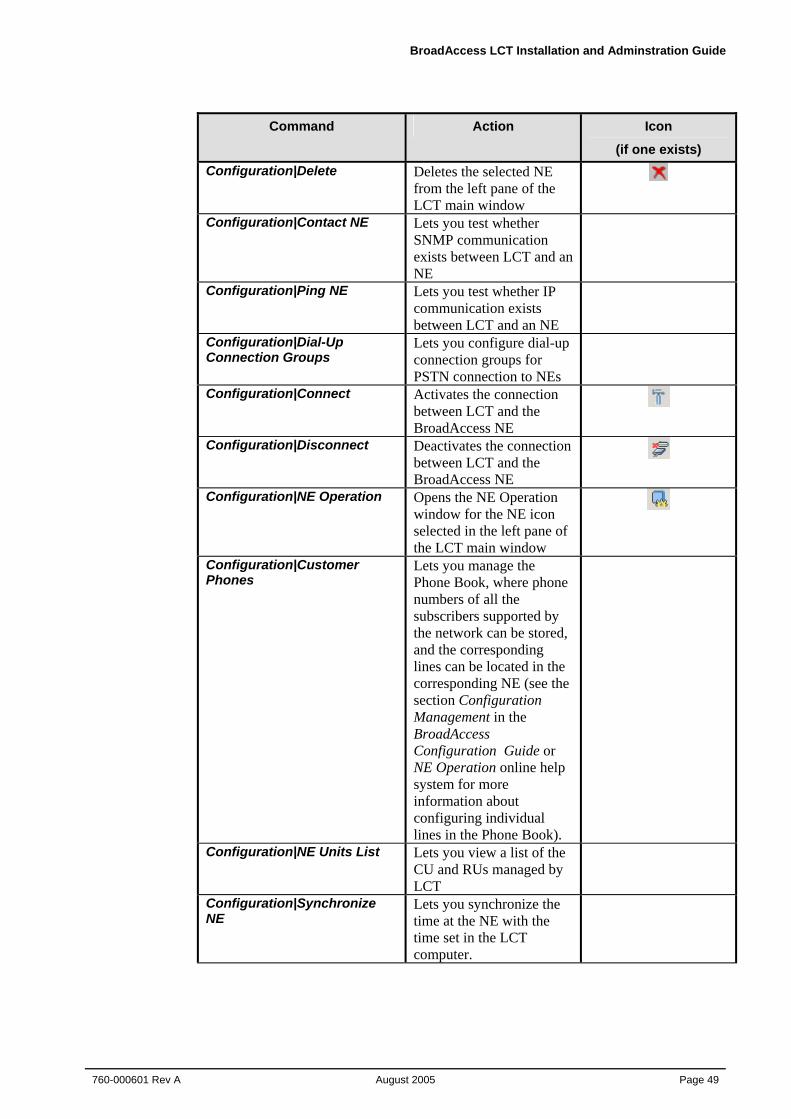
BroadAccess LCT Installation and Adminstration Guide
760-000601 Rev A August 2005
Page 49
Command Action Icon
(if one exists) Configuration|Delete Deletes the selected NE
from the left pane of the LCT main window
Configuration|Contact NE Lets you test whether SNMP communication exists between LCT and an NE
Configuration|Ping NE Lets you test whether IP communication exists between LCT and an NE
Configuration|Dial-Up Connection Groups
Lets you configure dial-up connection groups for PSTN connection to NEs
Configuration|Connect Activates the connection between LCT and the BroadAccess NE
Configuration|Disconnect Deactivates the connection between LCT and the BroadAccess NE
Configuration|NE Operation Opens the NE Operation window for the NE icon selected in the left pane of the LCT main window
Configuration|Customer Phones
Lets you manage the Phone Book, where phone numbers of all the subscribers supported by the network can be stored, and the corresponding lines can be located in the corresponding NE (see the section Configuration Management in the BroadAccess Configuration Guide or NE Operation online help system for more information about configuring individual lines in the Phone Book).
Configuration|NE Units List Lets you view a list of the CU and RUs managed by LCT
Configuration|Synchronize NE
Lets you synchronize the time at the NE with the time set in the LCT computer.
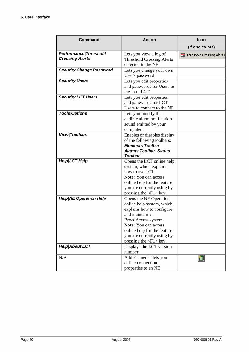
6. User Interface
Page 50 August 2005
760-000601 Rev A
Command Action Icon
(if one exists) Performance|Threshold Crossing Alerts
Lets you view a log of Threshold Crossing Alerts detected in the NE.
Security|Change Password Lets you change your own User's password
Security|Users Lets you edit properties and passwords for Users to log in to LCT
Security|LCT Users Lets you edit properties and passwords for LCT Users to connect to the NE
Tools|Options Lets you modify the audible alarm notification sound emitted by your computer
View|Toolbars Enables or disables display of the following toolbars: Elements Toolbar, Alarms Toolbar, Status Toolbar
Help|LCT Help Opens the LCT online help system, which explains how to use LCT. Note: You can access online help for the feature you are currently using by pressing the <F1> key.
Help|NE Operation Help Opens the NE Operation online help system, which explains how to configure and maintain a BroadAccess system. Note: You can access online help for the feature you are currently using by pressing the <F1> key.
Help|About LCT Displays the LCT version number
N/A Add Element - lets you define connection properties to an NE
BroadAccess LCT Installation and Adminstration Guide
760-000601 Rev A August 2005
Page 51
6.3. Creating Reports You filter data, and save or print reports about data collected by the system using the field chooser, database filter and the report designer.
To create a report:
1. Hide the columns in the table that you do not require (ATM Cross-Connect table, Alarm display and Dial-Up Alarms window only - see Hiding Columns in Tables of Data on page 51 for more information).
2. Sort, group and change the order of the columns in the table from which you want to generate the report.
3. Filter the desired data using the advanced database filter feature (see Using the Advanced Database Filter on page 52 for more information), or using the table's built-in grid filter (depending on the data you are viewing). If you want to use the same advanced database filter again in the future, you can save the filter to file.
4. Use the report designer to format the design of the report (see Using the Report Designer on page 55 for more information).
5. Print and/or save the report (in windows where print/save features are supported).
6.3.1. Hiding Columns of Data in Tables
You can hide columns in the alarm display and in the Dial-Up Alarms window, so that only the columns that you require are displayed. The columns will remain hidden every time you view that table, unless you drag the column headings from the field chooser back into the heading row of the table.
To hide columns in a table:
1. Click the Customize Columns button on the ClearAccess+/LCT main toolbar. A dialog box appears.
2. Drag the header cells of the columns you want to hide into the dialog box.
3. Close the window. The columns you dragged into dialog box are hidden.
To return hidden columns to the table:
1. Click the Customize Columns button. A dialog box appears.
2. Drag the header cells of the columns you want to display from the dialog box back to the table's header row.
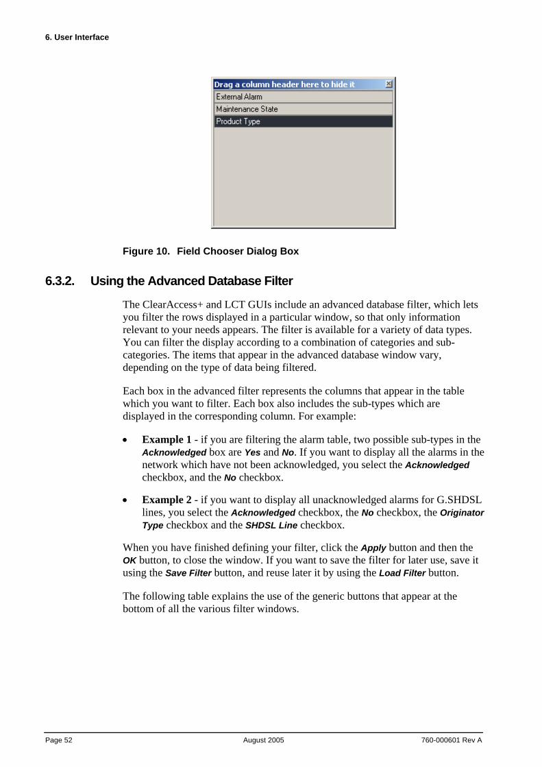
6. User Interface
Page 52 August 2005
760-000601 Rev A
Figure 10. Field Chooser Dialog Box
6.3.2. Using the Advanced Database Filter
The ClearAccess+ and LCT GUIs include an advanced database filter, which lets you filter the rows displayed in a particular window, so that only information relevant to your needs appears. The filter is available for a variety of data types. You can filter the display according to a combination of categories and sub-categories. The items that appear in the advanced database window vary, depending on the type of data being filtered.
Each box in the advanced filter represents the columns that appear in the table which you want to filter. Each box also includes the sub-types which are displayed in the corresponding column. For example:
• Example 1 - if you are filtering the alarm table, two possible sub-types in the Acknowledged box are Yes and No. If you want to display all the alarms in the network which have not been acknowledged, you select the Acknowledged checkbox, and the No checkbox.
• Example 2 - if you want to display all unacknowledged alarms for G.SHDSL lines, you select the Acknowledged checkbox, the No checkbox, the Originator Type checkbox and the SHDSL Line checkbox.
When you have finished defining your filter, click the Apply button and then the OK button, to close the window. If you want to save the filter for later use, save it using the Save Filter button, and reuse later it by using the Load Filter button.
The following table explains the use of the generic buttons that appear at the bottom of all the various filter windows.
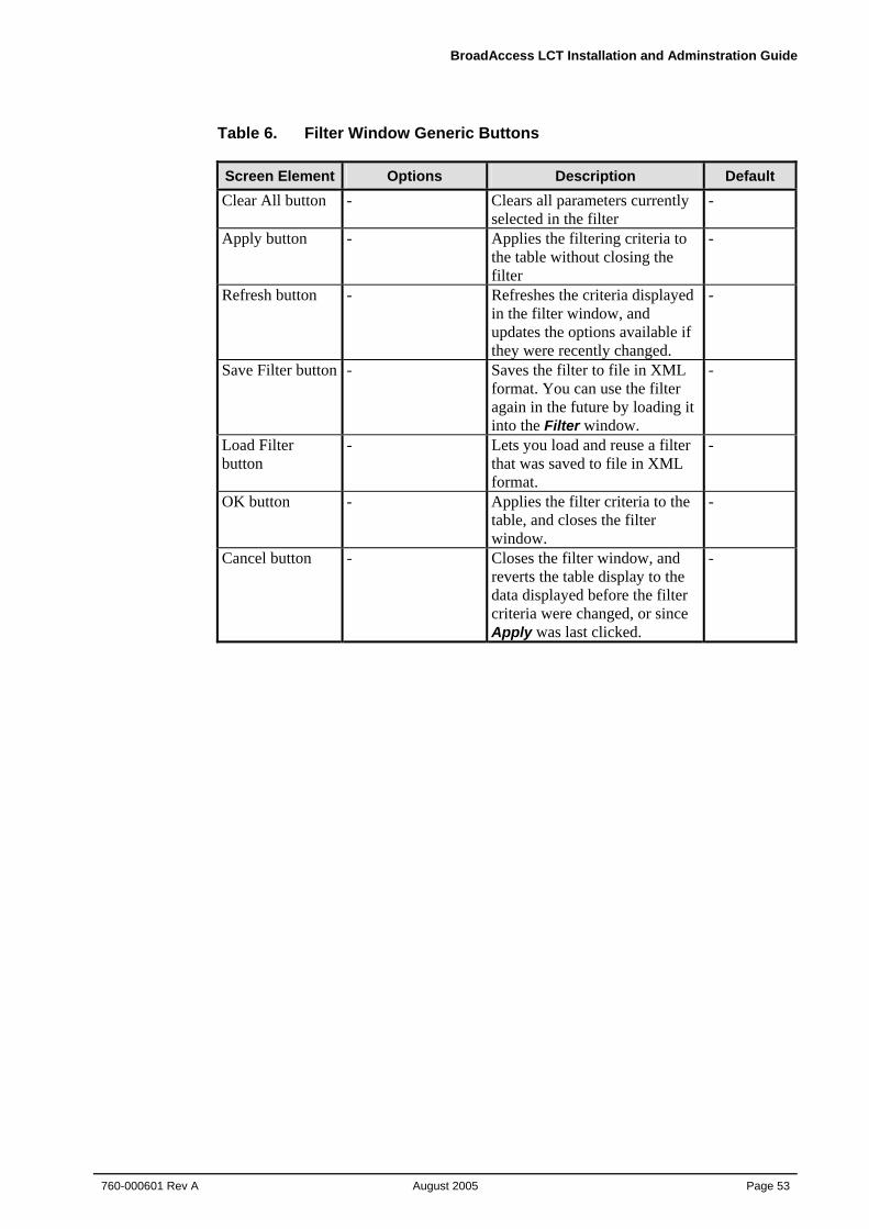
BroadAccess LCT Installation and Adminstration Guide
760-000601 Rev A August 2005
Page 53
Table 6. Filter Window Generic Buttons Screen Element Options Description Default Clear All button - Clears all parameters currently
selected in the filter -
Apply button - Applies the filtering criteria to the table without closing the filter
-
Refresh button - Refreshes the criteria displayed in the filter window, and updates the options available if they were recently changed.
-
Save Filter button - Saves the filter to file in XML format. You can use the filter again in the future by loading it into the Filter window.
-
Load Filter button
- Lets you load and reuse a filter that was saved to file in XML format.
-
OK button - Applies the filter criteria to the table, and closes the filter window.
-
Cancel button - Closes the filter window, and reverts the table display to the data displayed before the filter criteria were changed, or since Apply was last clicked.
-
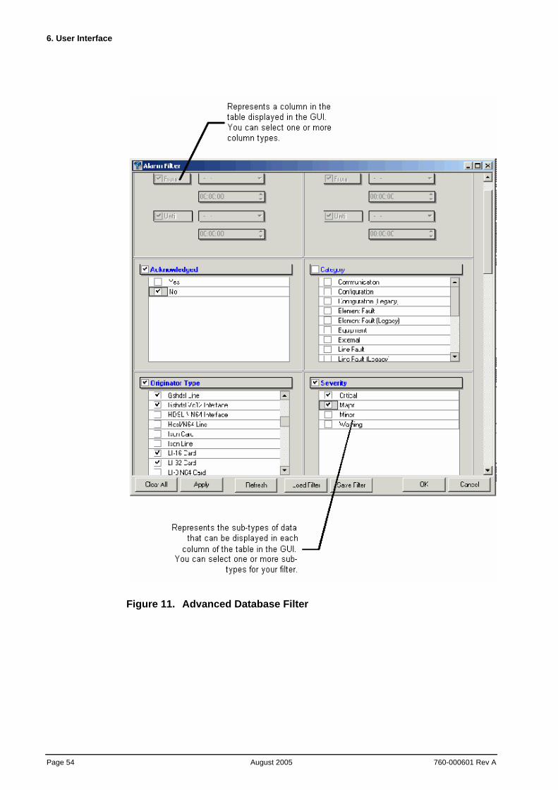
6. User Interface
Page 54 August 2005
760-000601 Rev A
Figure 11. Advanced Database Filter
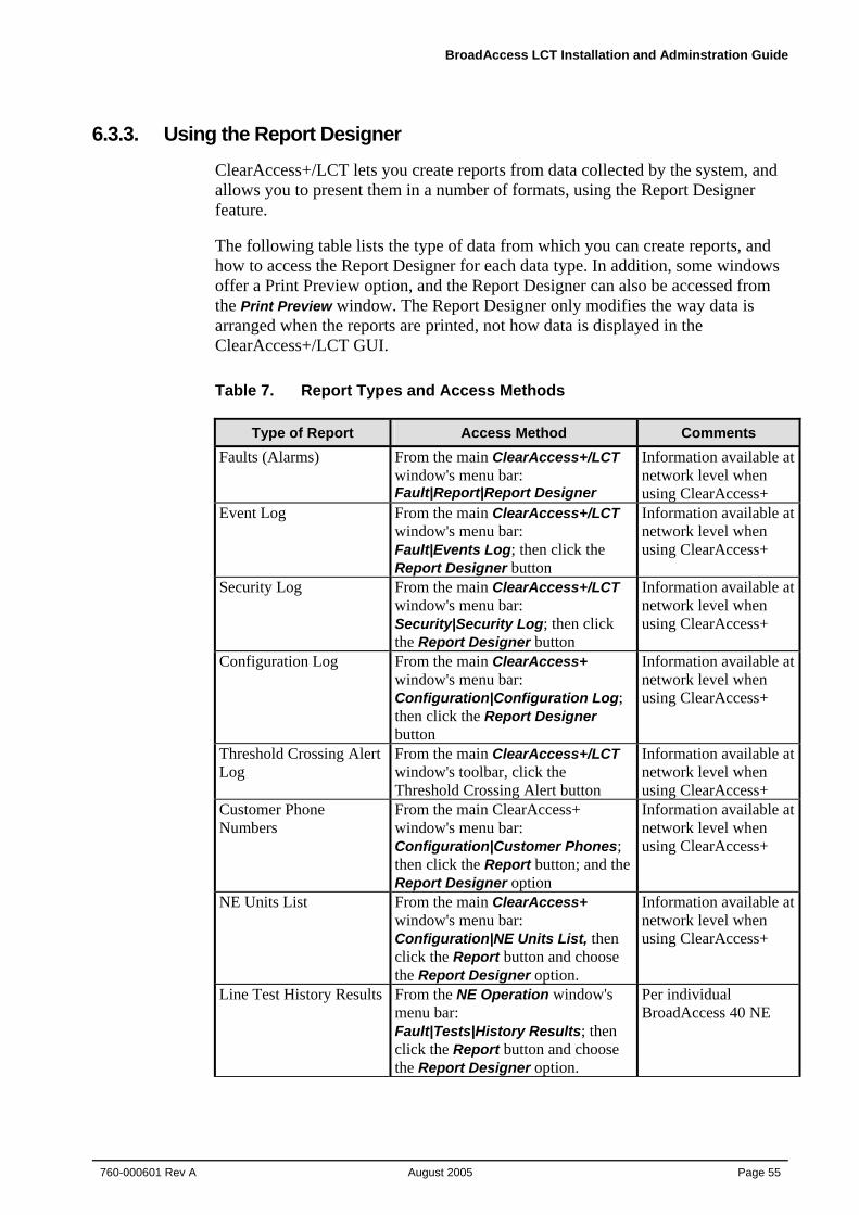
BroadAccess LCT Installation and Adminstration Guide
760-000601 Rev A August 2005
Page 55
6.3.3. Using the Report Designer ClearAccess+/LCT lets you create reports from data collected by the system, and allows you to present them in a number of formats, using the Report Designer feature.
The following table lists the type of data from which you can create reports, and how to access the Report Designer for each data type. In addition, some windows offer a Print Preview option, and the Report Designer can also be accessed from the Print Preview window. The Report Designer only modifies the way data is arranged when the reports are printed, not how data is displayed in the ClearAccess+/LCT GUI.
Table 7. Report Types and Access Methods
Type of Report Access Method Comments Faults (Alarms) From the main ClearAccess+/LCT
window's menu bar: Fault|Report|Report Designer
Information available at network level when using ClearAccess+
Event Log From the main ClearAccess+/LCT window's menu bar: Fault|Events Log; then click the Report Designer button
Information available at network level when using ClearAccess+
Security Log From the main ClearAccess+/LCT window's menu bar: Security|Security Log; then click the Report Designer button
Information available at network level when using ClearAccess+
Configuration Log From the main ClearAccess+ window's menu bar: Configuration|Configuration Log; then click the Report Designer button
Information available at network level when using ClearAccess+
Threshold Crossing Alert Log
From the main ClearAccess+/LCT window's toolbar, click the Threshold Crossing Alert button
Information available at network level when using ClearAccess+
Customer Phone Numbers
From the main ClearAccess+ window's menu bar: Configuration|Customer Phones; then click the Report button; and the Report Designer option
Information available at network level when using ClearAccess+
NE Units List From the main ClearAccess+ window's menu bar: Configuration|NE Units List, then click the Report button and choose the Report Designer option.
Information available at network level when using ClearAccess+
Line Test History Results From the NE Operation window's menu bar: Fault|Tests|History Results; then click the Report button and choose the Report Designer option.
Per individual BroadAccess 40 NE
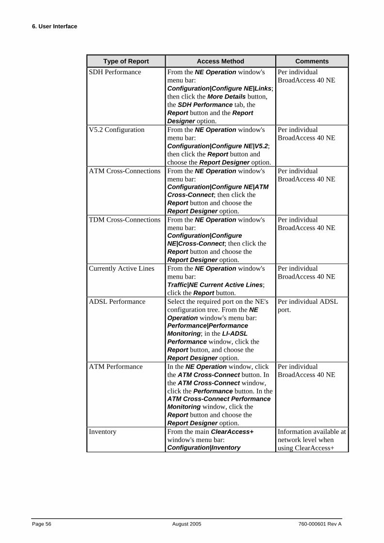
6. User Interface
Page 56 August 2005
760-000601 Rev A
Type of Report Access Method Comments SDH Performance From the NE Operation window's
menu bar: Configuration|Configure NE|Links; then click the More Details button, the SDH Performance tab, the Report button and the Report Designer option.
Per individual BroadAccess 40 NE
V5.2 Configuration From the NE Operation window's menu bar: Configuration|Configure NE|V5.2; then click the Report button and choose the Report Designer option.
Per individual BroadAccess 40 NE
ATM Cross-Connections From the NE Operation window's menu bar: Configuration|Configure NE|ATM Cross-Connect; then click the Report button and choose the Report Designer option.
Per individual BroadAccess 40 NE
TDM Cross-Connections From the NE Operation window's menu bar: Configuration|Configure NE|Cross-Connect; then click the Report button and choose the Report Designer option.
Per individual BroadAccess 40 NE
Currently Active Lines From the NE Operation window's menu bar: Traffic|NE Current Active Lines; click the Report button.
Per individual BroadAccess 40 NE
ADSL Performance Select the required port on the NE's configuration tree. From the NE Operation window's menu bar: Performance|Performance Monitoring; in the LI-ADSL Performance window, click the Report button, and choose the Report Designer option.
Per individual ADSL port.
ATM Performance In the NE Operation window, click the ATM Cross-Connect button. In the ATM Cross-Connect window, click the Performance button. In the ATM Cross-Connect Performance Monitoring window, click the Report button and choose the Report Designer option.
Per individual BroadAccess 40 NE
Inventory From the main ClearAccess+ window's menu bar: Configuration|Inventory
Information available at network level when using ClearAccess+
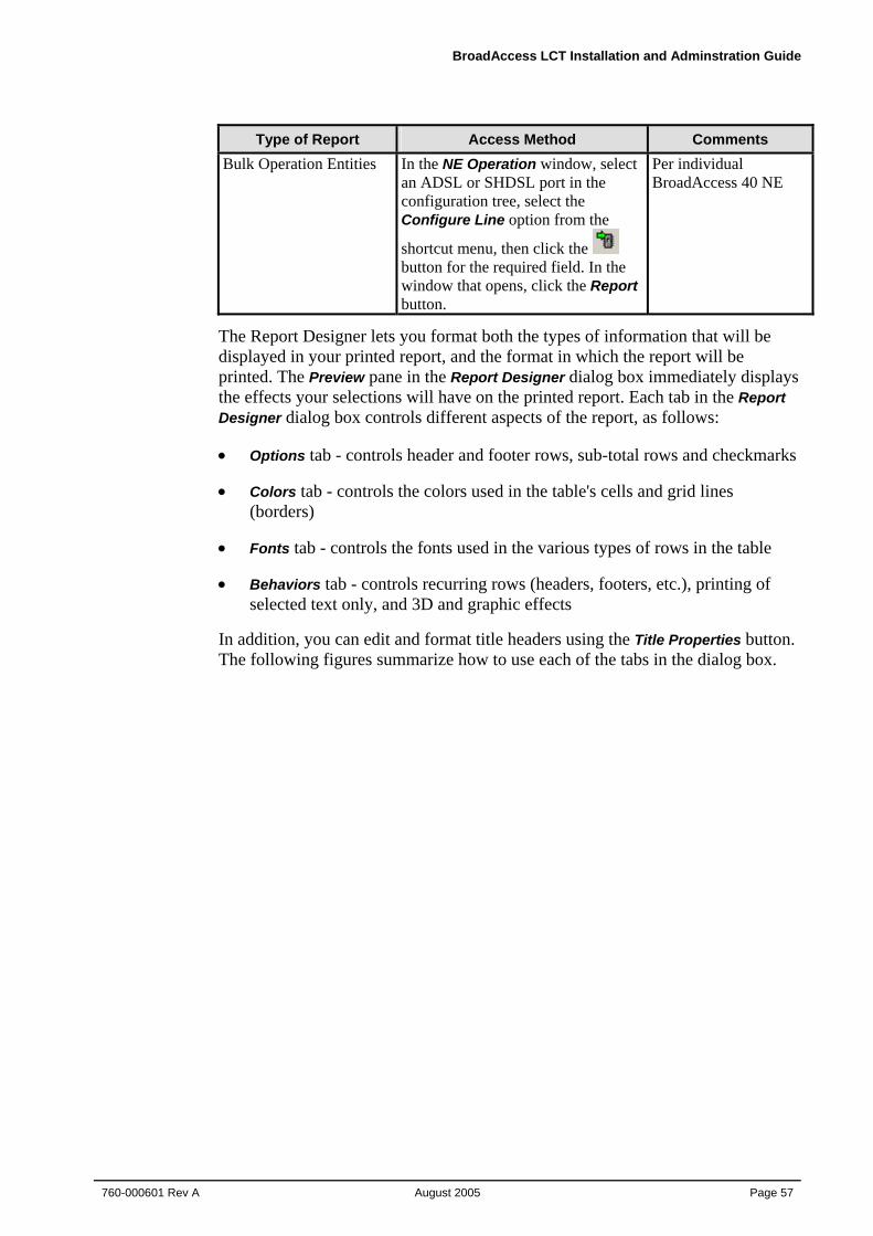
BroadAccess LCT Installation and Adminstration Guide
760-000601 Rev A August 2005
Page 57
Type of Report Access Method Comments Bulk Operation Entities In the NE Operation window, select
an ADSL or SHDSL port in the configuration tree, select the Configure Line option from the
shortcut menu, then click the button for the required field. In the window that opens, click the Report button.
Per individual BroadAccess 40 NE
The Report Designer lets you format both the types of information that will be displayed in your printed report, and the format in which the report will be printed. The Preview pane in the Report Designer dialog box immediately displays the effects your selections will have on the printed report. Each tab in the Report Designer dialog box controls different aspects of the report, as follows:
• Options tab - controls header and footer rows, sub-total rows and checkmarks
• Colors tab - controls the colors used in the table's cells and grid lines (borders)
• Fonts tab - controls the fonts used in the various types of rows in the table
• Behaviors tab - controls recurring rows (headers, footers, etc.), printing of selected text only, and 3D and graphic effects
In addition, you can edit and format title headers using the Title Properties button. The following figures summarize how to use each of the tabs in the dialog box.
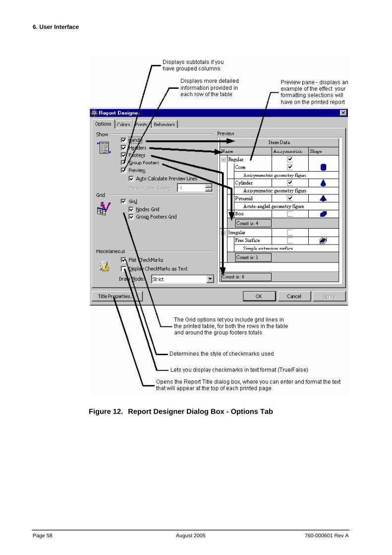
6. User Interface
Page 58 August 2005
760-000601 Rev A
Figure 12. Report Designer Dialog Box - Options Tab
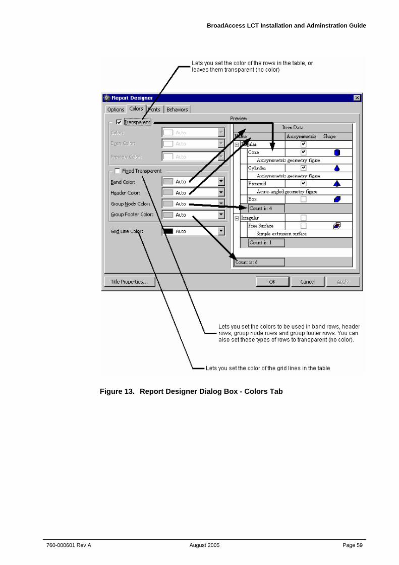
BroadAccess LCT Installation and Adminstration Guide
760-000601 Rev A August 2005
Page 59
Figure 13. Report Designer Dialog Box - Colors Tab
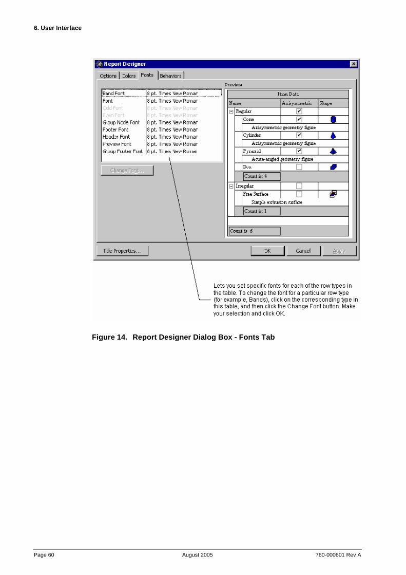
6. User Interface
Page 60 August 2005
760-000601 Rev A
Figure 14. Report Designer Dialog Box - Fonts Tab
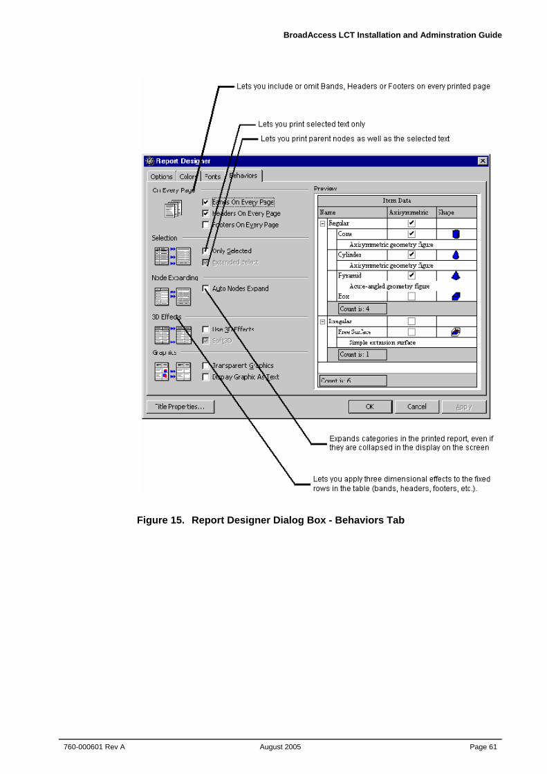
BroadAccess LCT Installation and Adminstration Guide
760-000601 Rev A August 2005
Page 61
Figure 15. Report Designer Dialog Box - Behaviors Tab

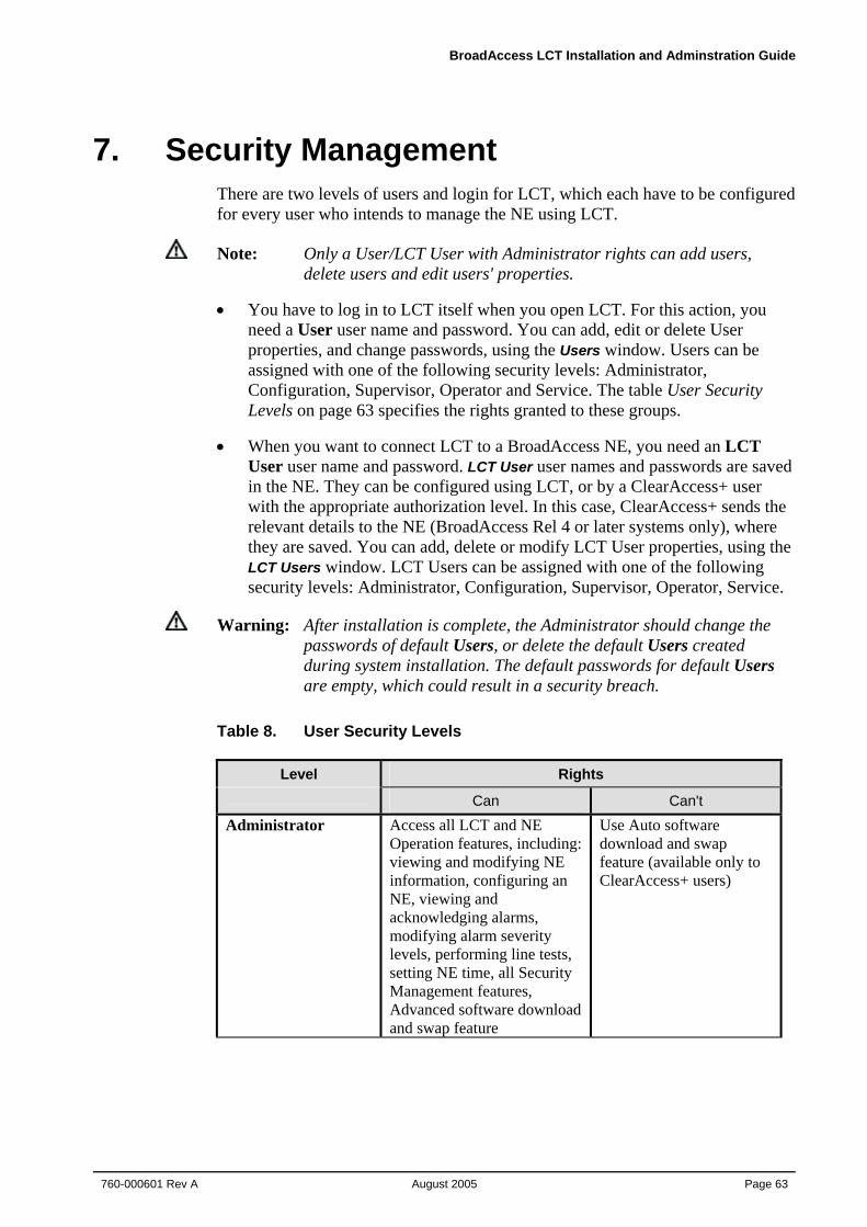
BroadAccess LCT Installation and Adminstration Guide
760-000601 Rev A August 2005
Page 63
7. Security Management There are two levels of users and login for LCT, which each have to be configured for every user who intends to manage the NE using LCT.
Note: Only a User/LCT User with Administrator rights can add users, delete users and edit users' properties.
• You have to log in to LCT itself when you open LCT. For this action, you need a User user name and password. You can add, edit or delete User properties, and change passwords, using the Users window. Users can be assigned with one of the following security levels: Administrator, Configuration, Supervisor, Operator and Service. The table User Security Levels on page 63 specifies the rights granted to these groups.
• When you want to connect LCT to a BroadAccess NE, you need an LCT User user name and password. LCT User user names and passwords are saved in the NE. They can be configured using LCT, or by a ClearAccess+ user with the appropriate authorization level. In this case, ClearAccess+ sends the relevant details to the NE (BroadAccess Rel 4 or later systems only), where they are saved. You can add, delete or modify LCT User properties, using the LCT Users window. LCT Users can be assigned with one of the following security levels: Administrator, Configuration, Supervisor, Operator, Service.
Warning: After installation is complete, the Administrator should change the passwords of default Users, or delete the default Users created during system installation. The default passwords for default Users are empty, which could result in a security breach.
Table 8. User Security Levels
Level Rights Can Can't
Administrator Access all LCT and NE Operation features, including: viewing and modifying NE information, configuring an NE, viewing and acknowledging alarms, modifying alarm severity levels, performing line tests, setting NE time, all Security Management features, Advanced software download and swap feature
Use Auto software download and swap feature (available only to ClearAccess+ users)
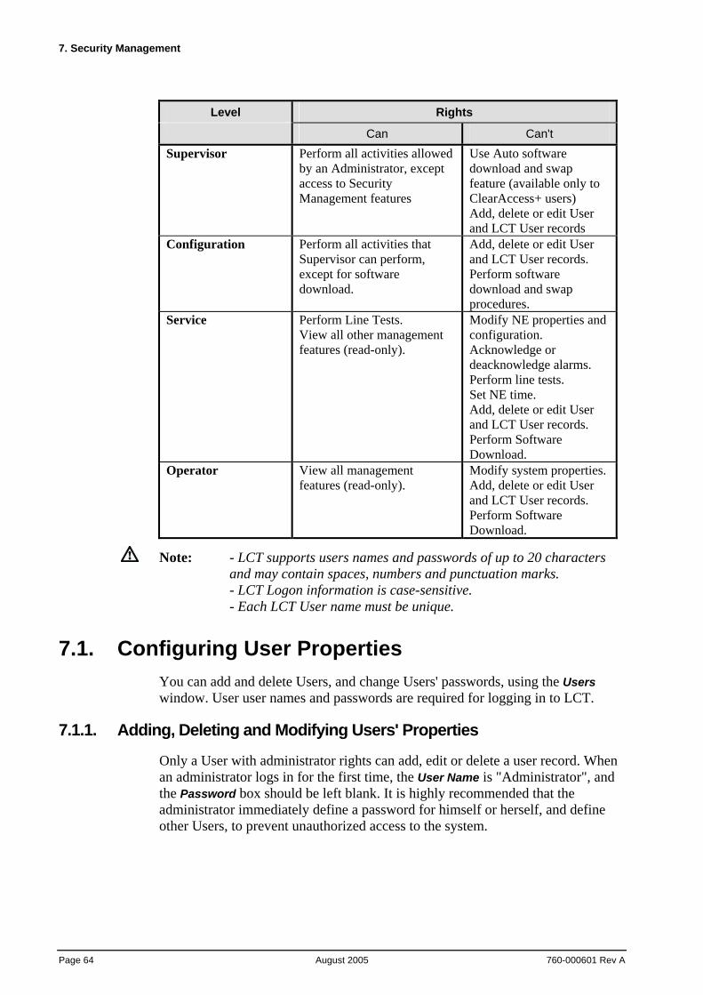
7. Security Management
Page 64 August 2005
760-000601 Rev A
Level Rights Can Can't
Supervisor Perform all activities allowed by an Administrator, except access to Security Management features
Use Auto software download and swap feature (available only to ClearAccess+ users) Add, delete or edit User and LCT User records
Configuration Perform all activities that Supervisor can perform, except for software download.
Add, delete or edit User and LCT User records. Perform software download and swap procedures.
Service Perform Line Tests. View all other management features (read-only).
Modify NE properties and configuration. Acknowledge or deacknowledge alarms. Perform line tests. Set NE time. Add, delete or edit User and LCT User records. Perform Software Download.
Operator View all management features (read-only).
Modify system properties. Add, delete or edit User and LCT User records. Perform Software Download.
Note: - LCT supports users names and passwords of up to 20 characters and may contain spaces, numbers and punctuation marks. - LCT Logon information is case-sensitive. - Each LCT User name must be unique.
7.1. Configuring User Properties You can add and delete Users, and change Users' passwords, using the Users window. User user names and passwords are required for logging in to LCT.
7.1.1. Adding, Deleting and Modifying Users' Properties
Only a User with administrator rights can add, edit or delete a user record. When an administrator logs in for the first time, the User Name is "Administrator", and the Password box should be left blank. It is highly recommended that the administrator immediately define a password for himself or herself, and define other Users, to prevent unauthorized access to the system.
BroadAccess LCT Installation and Adminstration Guide
760-000601 Rev A August 2005
Page 65
Note: - LCT supports user names and passwords of up to 20 characters and may contain spaces, numbers and punctuation marks. - LCT Login information is case-sensitive. - Each user name must be unique.
To add a new User:
1. Select the Security|Users menu option. The Users window appears.
2. Click the New Row button. The User Properties dialog box appears.
3. Click in the Username box and enter the user's name.
4. Select an authorization level from the Default Authorization drop-down box.
5. Click the OK button.
6. In the User Properties dialog box, click the Edit button. The User Properties dialog box appears. Click the Change Password button. The Change Password dialog box appears.
7. Type new password in the New Password and the Confirm New Password boxes and then click OK.
Note: In order to connect LCT to the NE, you also need to define LCT Users. For more information, see Configuring LCT User Properties on page 68).
To edit a User's properties:
1. Select the Security|Users menu option. The Users window appears.
2. Click on the cell in the table that you want to edit, and click the Edit button. The User Properties dialog box appears.
3. Make changes as required.
4. Click the OK button. The changes you made are saved.
Note: To cancel changes you have made and have not saved, click the Cancel button.
To delete a User:
1. Select the Security|Users menu option. The Users window appears.
2. Select the row corresponding to the User that you want to delete.
3. Click the Delete button.
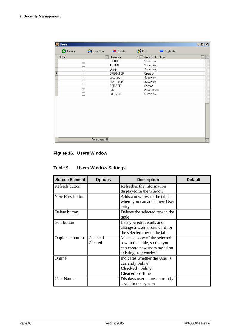
7. Security Management
Page 66 August 2005
760-000601 Rev A
Figure 16. Users Window
Table 9. Users Window Settings Screen Element Options Description Default Refresh button Refreshes the information
displayed in the window
New Row button Adds a new row to the table, where you can add a new User entry.
Delete button Deletes the selected row in the table
Edit button Lets you edit details and change a User’s password for the selected row in the table
Duplicate button Checked Cleared
Makes a copy of the selected row in the table, so that you can create new users based on existing user entries.
Online Indicates whether the User is currently online: Checked - online Cleared - offline
User Name Displays user names currently saved in the system
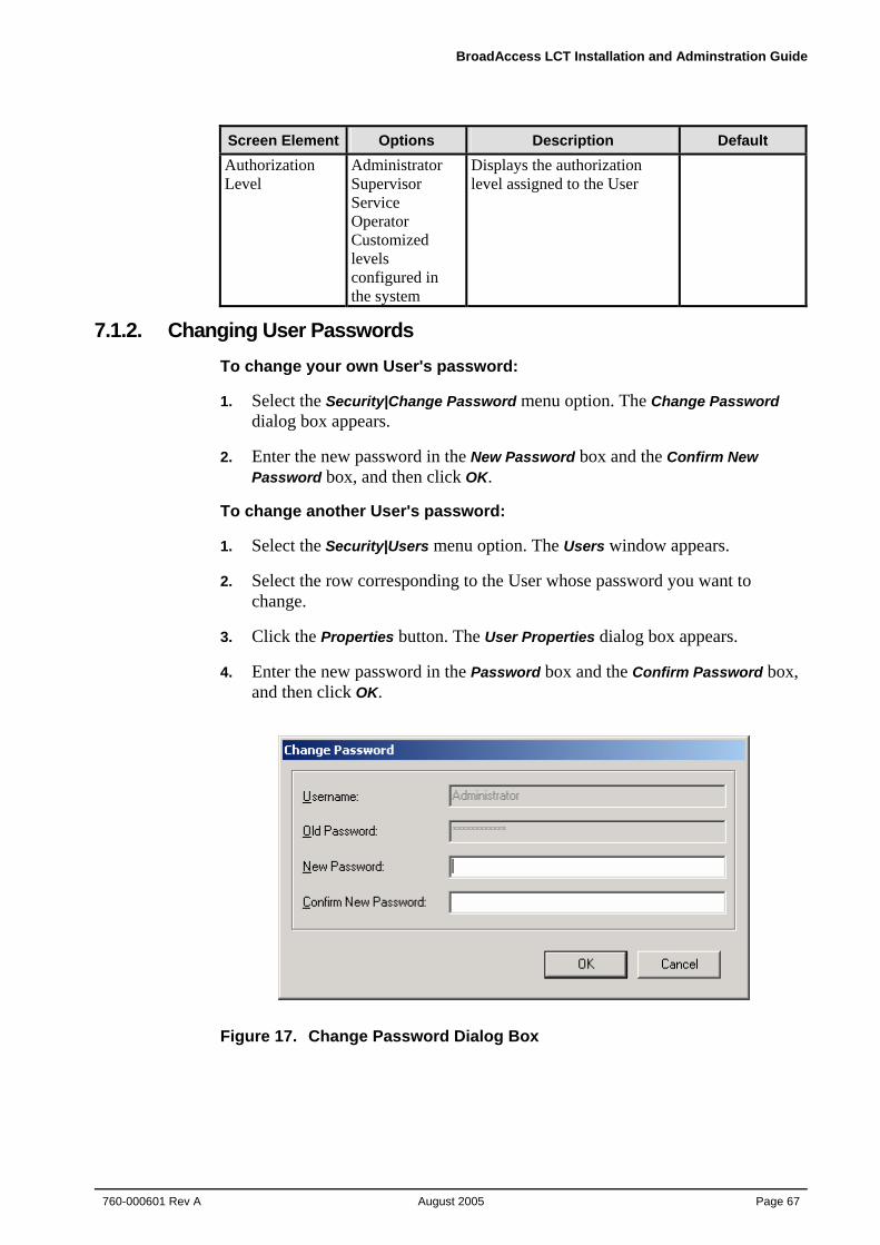
BroadAccess LCT Installation and Adminstration Guide
760-000601 Rev A August 2005
Page 67
Screen Element Options Description Default Authorization Level
Administrator Supervisor Service Operator Customized levels configured in the system
Displays the authorization level assigned to the User
7.1.2. Changing User Passwords To change your own User's password:
1. Select the Security|Change Password menu option. The Change Password dialog box appears.
2. Enter the new password in the New Password box and the Confirm New Password box, and then click OK.
To change another User's password:
1. Select the Security|Users menu option. The Users window appears.
2. Select the row corresponding to the User whose password you want to change.
3. Click the Properties button. The User Properties dialog box appears.
4. Enter the new password in the Password box and the Confirm Password box, and then click OK.
Figure 17. Change Password Dialog Box
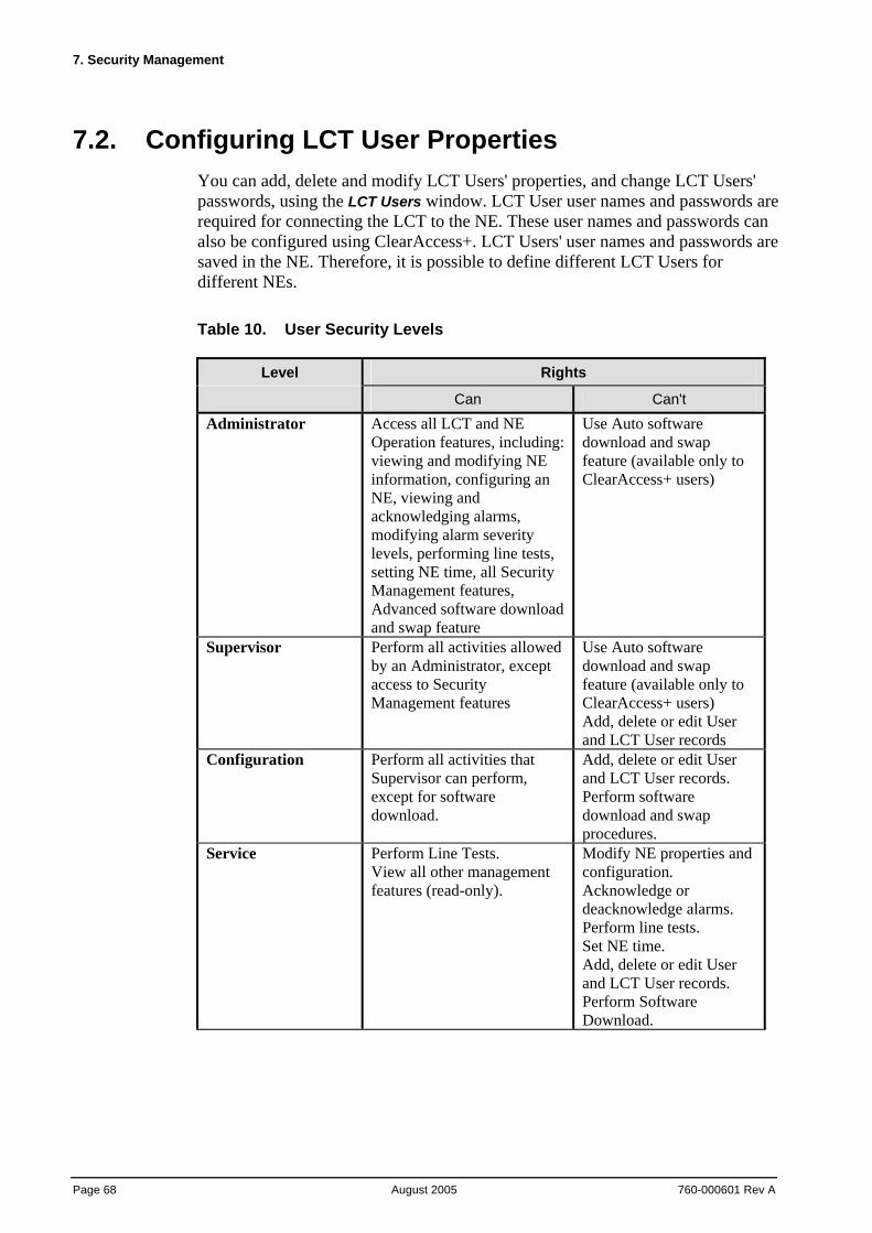
7. Security Management
Page 68 August 2005
760-000601 Rev A
7.2. Configuring LCT User Properties You can add, delete and modify LCT Users' properties, and change LCT Users' passwords, using the LCT Users window. LCT User user names and passwords are required for connecting the LCT to the NE. These user names and passwords can also be configured using ClearAccess+. LCT Users' user names and passwords are saved in the NE. Therefore, it is possible to define different LCT Users for different NEs.
Table 10. User Security Levels
Level Rights Can Can't
Administrator Access all LCT and NE Operation features, including: viewing and modifying NE information, configuring an NE, viewing and acknowledging alarms, modifying alarm severity levels, performing line tests, setting NE time, all Security Management features, Advanced software download and swap feature
Use Auto software download and swap feature (available only to ClearAccess+ users)
Supervisor Perform all activities allowed by an Administrator, except access to Security Management features
Use Auto software download and swap feature (available only to ClearAccess+ users) Add, delete or edit User and LCT User records
Configuration Perform all activities that Supervisor can perform, except for software download.
Add, delete or edit User and LCT User records. Perform software download and swap procedures.
Service Perform Line Tests. View all other management features (read-only).
Modify NE properties and configuration. Acknowledge or deacknowledge alarms. Perform line tests. Set NE time. Add, delete or edit User and LCT User records. Perform Software Download.
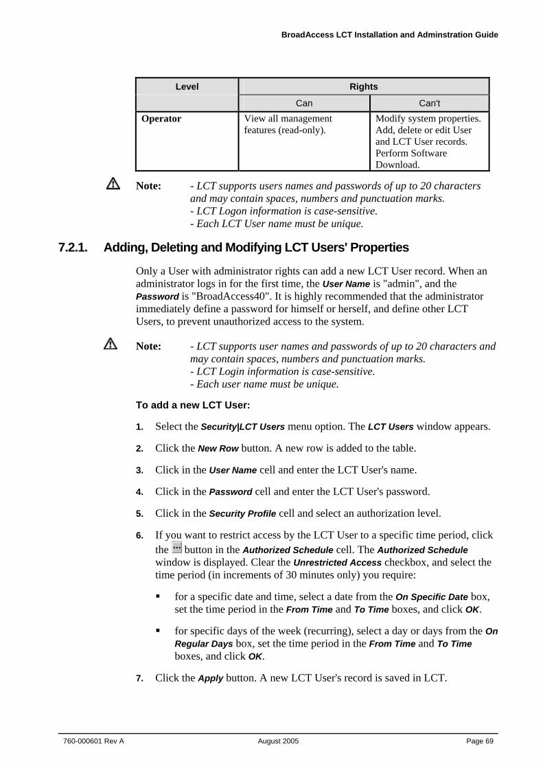
BroadAccess LCT Installation and Adminstration Guide
760-000601 Rev A August 2005
Page 69
Level Rights Can Can't
Operator View all management features (read-only).
Modify system properties. Add, delete or edit User and LCT User records. Perform Software Download.
Note: - LCT supports users names and passwords of up to 20 characters and may contain spaces, numbers and punctuation marks. - LCT Logon information is case-sensitive. - Each LCT User name must be unique.
7.2.1. Adding, Deleting and Modifying LCT Users' Properties
Only a User with administrator rights can add a new LCT User record. When an administrator logs in for the first time, the User Name is "admin", and the Password is "BroadAccess40". It is highly recommended that the administrator immediately define a password for himself or herself, and define other LCT Users, to prevent unauthorized access to the system.
Note: - LCT supports user names and passwords of up to 20 characters and may contain spaces, numbers and punctuation marks. - LCT Login information is case-sensitive. - Each user name must be unique.
To add a new LCT User:
1. Select the Security|LCT Users menu option. The LCT Users window appears.
2. Click the New Row button. A new row is added to the table.
3. Click in the User Name cell and enter the LCT User's name.
4. Click in the Password cell and enter the LCT User's password.
5. Click in the Security Profile cell and select an authorization level.
6. If you want to restrict access by the LCT User to a specific time period, click the button in the Authorized Schedule cell. The Authorized Schedule window is displayed. Clear the Unrestricted Access checkbox, and select the time period (in increments of 30 minutes only) you require:
for a specific date and time, select a date from the On Specific Date box, set the time period in the From Time and To Time boxes, and click OK.
for specific days of the week (recurring), select a day or days from the On Regular Days box, set the time period in the From Time and To Time boxes, and click OK.
7. Click the Apply button. A new LCT User's record is saved in LCT.
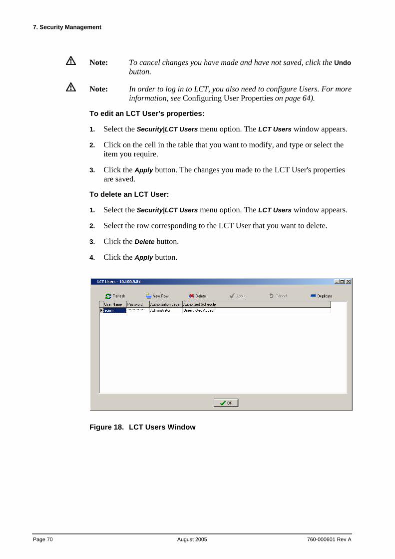
7. Security Management
Page 70 August 2005
760-000601 Rev A
Note: To cancel changes you have made and have not saved, click the Undo
button.
Note: In order to log in to LCT, you also need to configure Users. For more information, see Configuring User Properties on page 64).
To edit an LCT User's properties:
1. Select the Security|LCT Users menu option. The LCT Users window appears.
2. Click on the cell in the table that you want to modify, and type or select the item you require.
3. Click the Apply button. The changes you made to the LCT User's properties are saved.
To delete an LCT User:
1. Select the Security|LCT Users menu option. The LCT Users window appears.
2. Select the row corresponding to the LCT User that you want to delete.
3. Click the Delete button.
4. Click the Apply button.
Figure 18. LCT Users Window
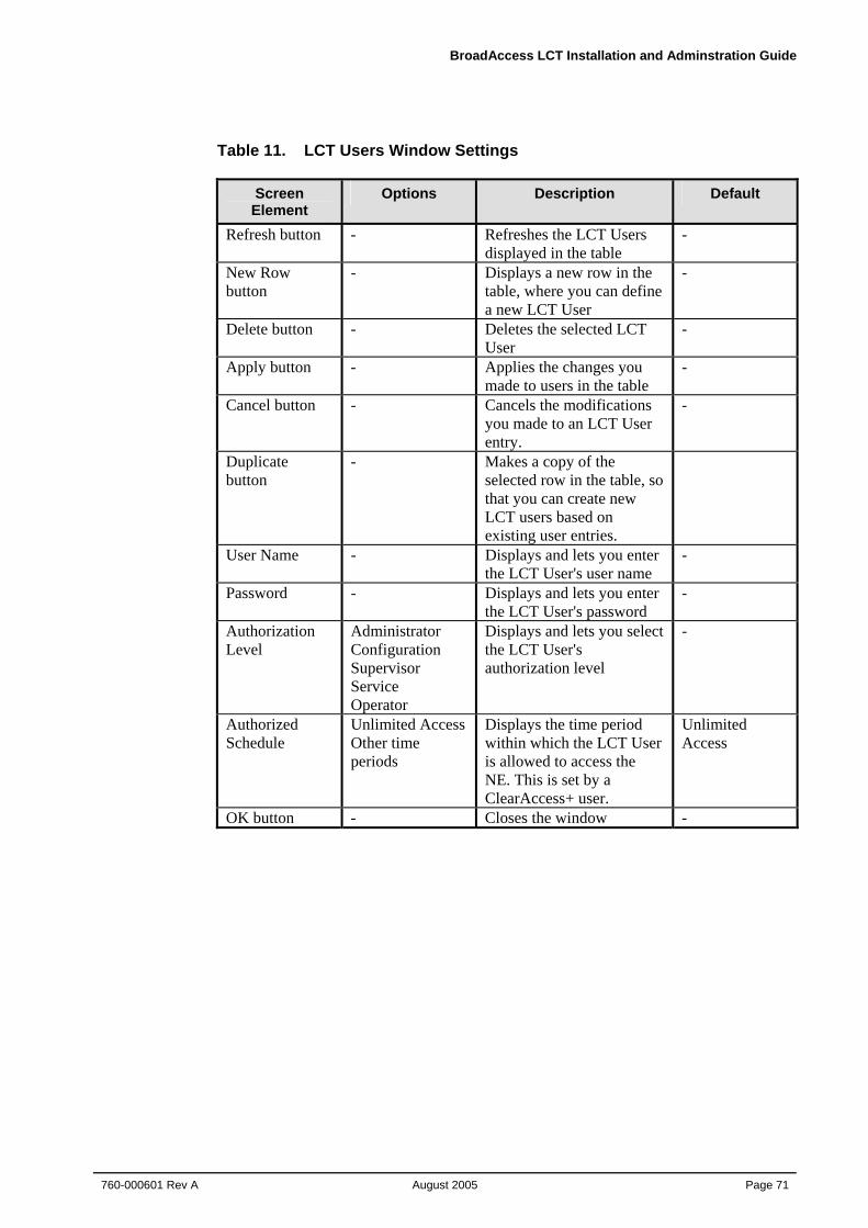
BroadAccess LCT Installation and Adminstration Guide
760-000601 Rev A August 2005
Page 71
Table 11. LCT Users Window Settings
Screen Element
Options Description Default
Refresh button - Refreshes the LCT Users displayed in the table
-
New Row button
- Displays a new row in the table, where you can define a new LCT User
-
Delete button - Deletes the selected LCT User
-
Apply button - Applies the changes you made to users in the table
-
Cancel button - Cancels the modifications you made to an LCT User entry.
-
Duplicate button
- Makes a copy of the selected row in the table, so that you can create new LCT users based on existing user entries.
User Name - Displays and lets you enter the LCT User's user name
-
Password - Displays and lets you enter the LCT User's password
-
Authorization Level
Administrator Configuration Supervisor Service Operator
Displays and lets you select the LCT User's authorization level
-
Authorized Schedule
Unlimited Access Other time periods
Displays the time period within which the LCT User is allowed to access the NE. This is set by a ClearAccess+ user.
Unlimited Access
OK button - Closes the window -
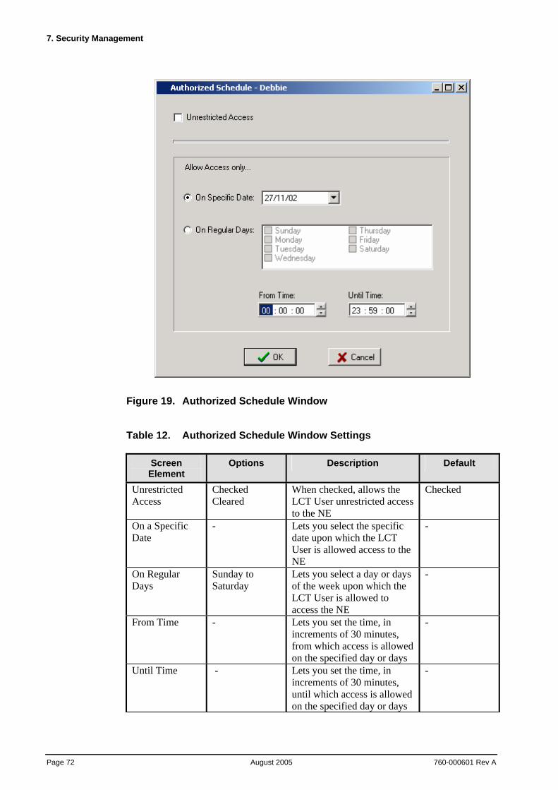
7. Security Management
Page 72 August 2005
760-000601 Rev A
Figure 19. Authorized Schedule Window
Table 12. Authorized Schedule Window Settings
Screen Element
Options Description Default
Unrestricted Access
Checked Cleared
When checked, allows the LCT User unrestricted access to the NE
Checked
On a Specific Date
- Lets you select the specific date upon which the LCT User is allowed access to the NE
-
On Regular Days
Sunday to Saturday
Lets you select a day or days of the week upon which the LCT User is allowed to access the NE
-
From Time - Lets you set the time, in increments of 30 minutes, from which access is allowed on the specified day or days
-
Until Time - Lets you set the time, in increments of 30 minutes, until which access is allowed on the specified day or days
-
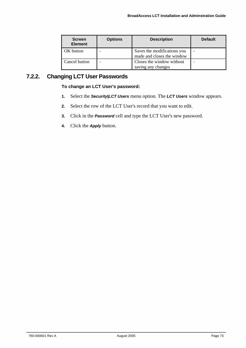
BroadAccess LCT Installation and Adminstration Guide
760-000601 Rev A August 2005
Page 73
Screen Element
Options Description Default
OK button - Saves the modifications you made and closes the window
-
Cancel button - Closes the window without saving any changes
-
7.2.2. Changing LCT User Passwords To change an LCT User's password:
1. Select the Security|LCT Users menu option. The LCT Users window appears.
2. Select the row of the LCT User's record that you want to edit.
3. Click in the Password cell and type the LCT User's new password.
4. Click the Apply button.

BroadAccess LCT Installation and Adminstration Guide
760-000601 Rev A August 2005
Page 75
8. IP Networking This section explains how IP networking is used in ClearAccess+ and BroadAccess 40 SNMP systems. It also explains how to Ping an NE and how to test SNMP communication with an NE. In addition, instructions are provided for configuring the ATM and PPP interfaces.
IP Networking is used in the BroadAccess 40 system to facilitate management using SNMP and Telnet protocols (Telnet can be used for stand-alone RUs only). For these purposes, the CU and RUs are factory configured with IP addresses and subnet masks, some of which can be modified.
The CU is factory-configured with the following:
• External IP Address and Subnet Mask - allows communication with the Carrier's IP network, including communication with the ClearAccess+ server or with LCT. This can be modified, if required. If more than one BroadAccess system is managed by ClearAccess+, the IP address must be changed, because each BroadAccess NE must have a unique address in the Carrier's network.
• Default Gateway - allows communication with Carrier's IP network, including communication with the ClearAccess+ server or with LCT, in cases when ClearAccess+ or LCT reside on a different network to the CU external IP address. This can be modified, if required, but must belong to the same external network as the CU.
• Internal IP Address and Subnet Mask - allows communication with the RUs, and is used to define the NE when using an LCT which is connected to an RU. The network address can be modified (if necessary), but the subnet mask and the last number in the IP Address cannot be modified.
Each RU is factory-configured with the following:
• External IP Address and Subnet Mask - allow communication with LCT (GUI or Telnet) connected to the RU. This IP address can be modified, but after Reset, the RU reverts to its default address until communication with the CU is established. The LCT computer must be configured with an IP address on the same network as the RU.
• Internal IP Address and Subnet Mask - allows communication with the CU. The last number in the IP address and the subnet mask cannot be modified, but the network on which the RUs and CU reside can be modified.
The following figure and table summarize how IP Networking is used in the BroadAccess system, and list the default IP Addresses and Subnet Masks. In most cases, there is no need to modify the CU and RUs' IP Addresses and Subnet Masks, with the exception of the CU external IP Address and Subnet Mask. However, if you do wish to modify them, refer to Configuring IP Addresses on page 78 for more information.
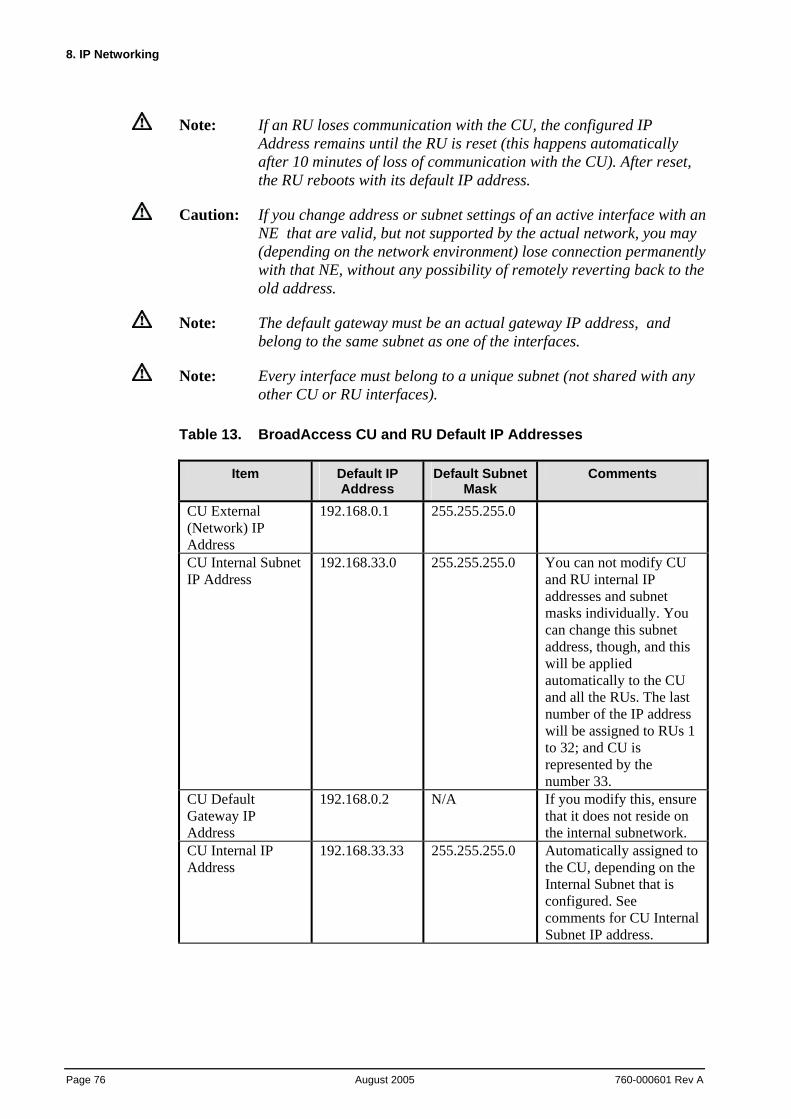
8. IP Networking
Page 76 August 2005
760-000601 Rev A
Note: If an RU loses communication with the CU, the configured IP Address remains until the RU is reset (this happens automatically after 10 minutes of loss of communication with the CU). After reset, the RU reboots with its default IP address.
Caution: If you change address or subnet settings of an active interface with an NE that are valid, but not supported by the actual network, you may (depending on the network environment) lose connection permanently with that NE, without any possibility of remotely reverting back to the old address.
Note: The default gateway must be an actual gateway IP address, and belong to the same subnet as one of the interfaces.
Note: Every interface must belong to a unique subnet (not shared with any other CU or RU interfaces).
Table 13. BroadAccess CU and RU Default IP Addresses
Item Default IP Address
Default Subnet Mask
Comments
CU External (Network) IP Address
192.168.0.1 255.255.255.0
CU Internal Subnet IP Address
192.168.33.0 255.255.255.0 You can not modify CU and RU internal IP addresses and subnet masks individually. You can change this subnet address, though, and this will be applied automatically to the CU and all the RUs. The last number of the IP address will be assigned to RUs 1 to 32; and CU is represented by the number 33.
CU Default Gateway IP Address
192.168.0.2 N/A If you modify this, ensure that it does not reside on the internal subnetwork.
CU Internal IP Address
192.168.33.33 255.255.255.0 Automatically assigned to the CU, depending on the Internal Subnet that is configured. See comments for CU Internal Subnet IP address.
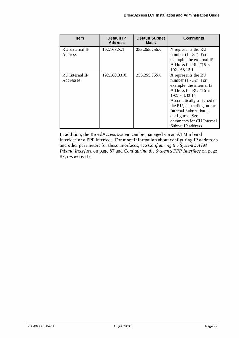
BroadAccess LCT Installation and Adminstration Guide
760-000601 Rev A August 2005
Page 77
Item Default IP Address
Default Subnet Mask
Comments
RU External IP Address
192.168.X.1 255.255.255.0 X represents the RU number (1 - 32). For example, the external IP Address for RU #15 is 192.168.15.1
RU Internal IP Addresses
192.168.33.X 255.255.255.0 X represents the RU number (1 - 32). For example, the internal IP Address for RU #15 is 192.168.33.15 Automatically assigned to the RU, depending on the Internal Subnet that is configured. See comments for CU Internal Subnet IP address.
In addition, the BroadAccess system can be managed via an ATM inband interface or a PPP interface. For more information about configuring IP addresses and other parameters for these interfaces, see Configuring the System's ATM Inband Interface on page 87 and Configuring the System's PPP Interface on page 87, respectively.
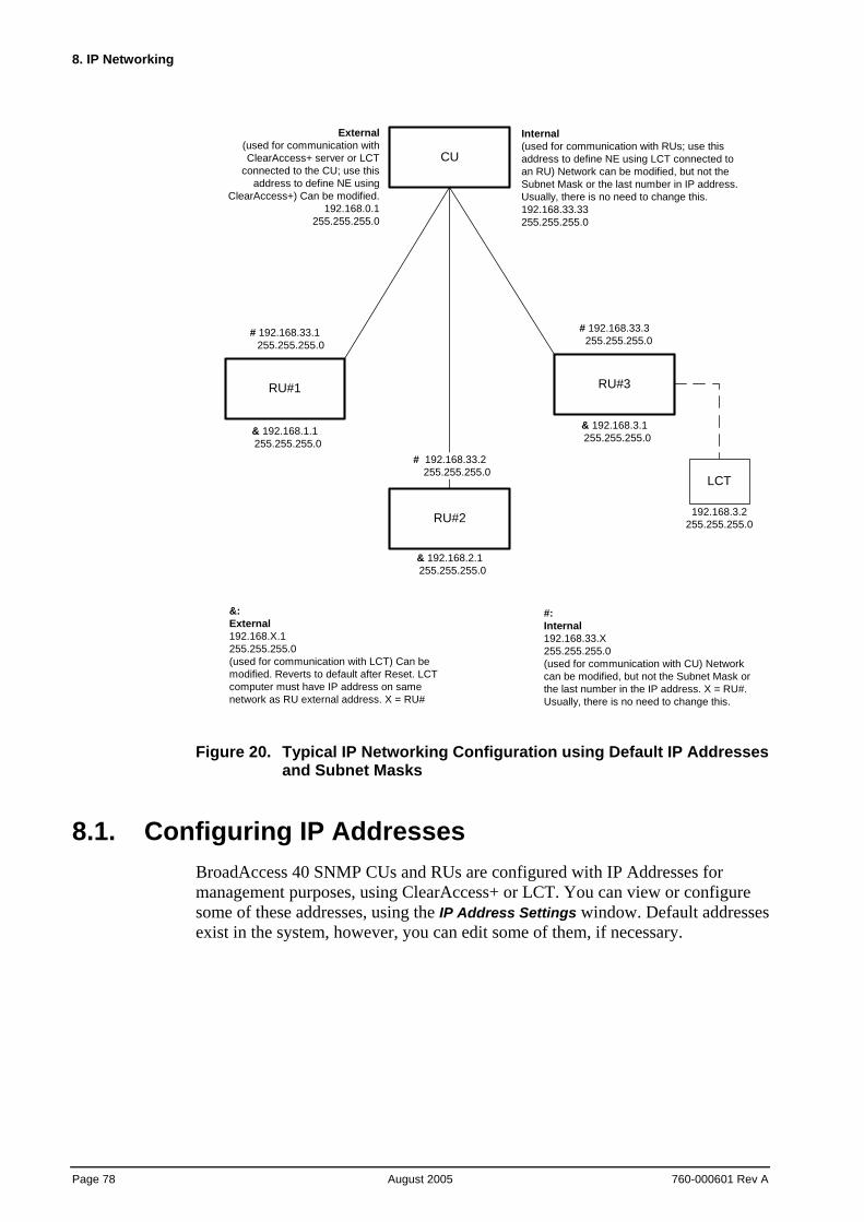
8. IP Networking
Page 78 August 2005
760-000601 Rev A
CU
RU#3
RU#2
RU#1
External(used for communication withClearAccess+ server or LCT
connected to the CU; use thisaddress to define NE using
ClearAccess+) Can be modified.192.168.0.1
255.255.255.0
Internal(used for communication with RUs; use thisaddress to define NE using LCT connected toan RU) Network can be modified, but not theSubnet Mask or the last number in IP address.Usually, there is no need to change this.192.168.33.33255.255.255.0
#:Internal192.168.33.X255.255.255.0(used for communication with CU) Networkcan be modified, but not the Subnet Mask orthe last number in the IP address. X = RU#.Usually, there is no need to change this.
# 192.168.33.1 255.255.255.0
# 192.168.33.3 255.255.255.0
&:External192.168.X.1255.255.255.0(used for communication with LCT) Can bemodified. Reverts to default after Reset. LCTcomputer must have IP address on samenetwork as RU external address. X = RU#
& 192.168.1.1 255.255.255.0
& 192.168.2.1 255.255.255.0
& 192.168.3.1 255.255.255.0
LCT
192.168.3.2255.255.255.0
# 192.168.33.2 255.255.255.0
Figure 20. Typical IP Networking Configuration using Default IP Addresses and Subnet Masks
8.1. Configuring IP Addresses BroadAccess 40 SNMP CUs and RUs are configured with IP Addresses for management purposes, using ClearAccess+ or LCT. You can view or configure some of these addresses, using the IP Address Settings window. Default addresses exist in the system, however, you can edit some of them, if necessary.
BroadAccess LCT Installation and Adminstration Guide
760-000601 Rev A August 2005
Page 79
The following can be modified, using the IP Address Settings window:
• CU Network (external) IP address, subnet mask and default gateway, which are used for communication between the CU and the carrier's IP network (required for ClearAccess+ and LCT connected to the CU)
• Internal subnet (Ethernet) IP address (subnet mask cannot be edited), which enables communication between the CU and the RUs. Internal IP Addresses are automatically assigned to the CU and RUs, based on the subnet IP address defined here.
• RU External IP addresses and subnet masks, which enable communication between each RU and an LCT computer
• PPP interface, which enables management of the NE using a PSTN connection (for more information, about management over PSTN, see the Configuration section of the ClearAccess+ Installation and Administration Guide/ClearAccess+ online help system. For more information about configuring the PPP interface, see Configuring the System's PPP Interface on page 87.)
• ATM Inband interface, which enables management of the NE using an ATM inband connection (for more information about configuring the ATM Inband interface, see Configuring the System's ATM Inband Interface on page 87)
For a more detailed explanation about IP Networking for the BroadAccess system, and default IP Addresses, see IP Networking on page 75.
Note: If an RU loses communication with the CU, the configured IP Address remains until the RU is reset (this happens automatically after 10 minutes of loss of communication with the CU). After reset, the RU reboots with its default IP address.
Note: You can also change the CU's network IP address using HyperTerminal. For more information, see Changing a CU's Network IP Address Using HyperTerminal on page 88 (LCT Installation and Administration Guide or LCT online help system).
To configure the CU's network (external) IP address, subnet mask and default gateway:
1. Point to a BroadAccess NE and right-click. The shortcut menu is displayed.
2. Select the NE Operation option. The NE Operation window appears.
3. From the NE Operation Menu Bar, select the Configuration option and then the IP Address Settings option. The IP Address Settings window appears.
4. On the CU Interfaces tab, enter the required addresses in the Ethernet Interface box (IP Address, Subnet Mask), and the default gateway address in the Default Gateway box.
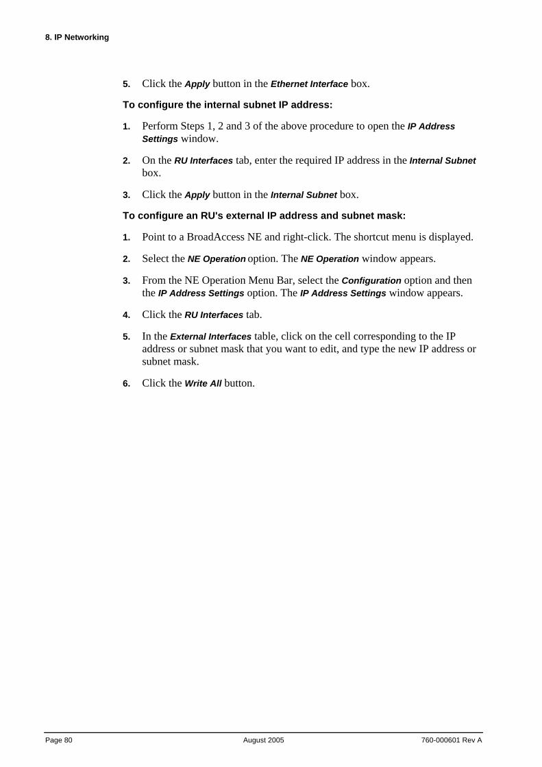
8. IP Networking
Page 80 August 2005
760-000601 Rev A
5. Click the Apply button in the Ethernet Interface box.
To configure the internal subnet IP address:
1. Perform Steps 1, 2 and 3 of the above procedure to open the IP Address Settings window.
2. On the RU Interfaces tab, enter the required IP address in the Internal Subnet box.
3. Click the Apply button in the Internal Subnet box.
To configure an RU's external IP address and subnet mask:
1. Point to a BroadAccess NE and right-click. The shortcut menu is displayed.
2. Select the NE Operation option. The NE Operation window appears.
3. From the NE Operation Menu Bar, select the Configuration option and then the IP Address Settings option. The IP Address Settings window appears.
4. Click the RU Interfaces tab.
5. In the External Interfaces table, click on the cell corresponding to the IP address or subnet mask that you want to edit, and type the new IP address or subnet mask.
6. Click the Write All button.
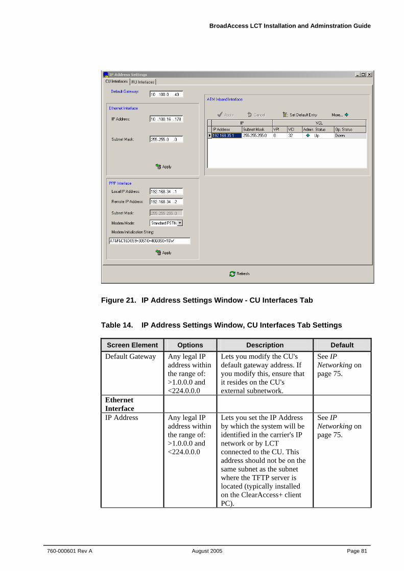
BroadAccess LCT Installation and Adminstration Guide
760-000601 Rev A August 2005
Page 81
Figure 21. IP Address Settings Window - CU Interfaces Tab
Table 14. IP Address Settings Window, CU Interfaces Tab Settings
Screen Element Options Description Default Default Gateway Any legal IP
address within the range of: >1.0.0.0 and <224.0.0.0
Lets you modify the CU's default gateway address. If you modify this, ensure that it resides on the CU's external subnetwork.
See IP Networking on page 75.
Ethernet Interface
IP Address Any legal IP address within the range of: >1.0.0.0 and <224.0.0.0
Lets you set the IP Address by which the system will be identified in the carrier's IP network or by LCT connected to the CU. This address should not be on the same subnet as the subnet where the TFTP server is located (typically installed on the ClearAccess+ client PC).
See IP Networking on page 75.
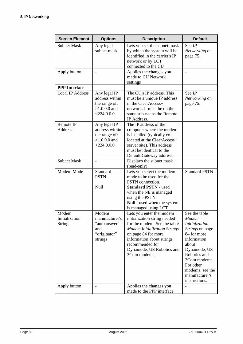
8. IP Networking
Page 82 August 2005
760-000601 Rev A
Screen Element Options Description Default Subnet Mask Any legal
subnet mask Lets you set the subnet mask by which the system will be identified in the carrier's IP network or by LCT connected to the CU
See IP Networking on page 75.
Apply button - Applies the changes you made to CU Network settings
-
PPP Interface Local IP Address Any legal IP
address within the range of: >1.0.0.0 and <224.0.0.0
The CU's IP address. This must be a unique IP address in the ClearAccess+ network. It must be on the same sub-net as the Remote IP Address.
See IP Networking on page 75.
Remote IP Address
Any legal IP address within the range of: >1.0.0.0 and <224.0.0.0
The IP address of the computer where the modem is installed (typically co-located at the ClearAccess+ server site). This address must be identical to the Default Gateway address.
Subnet Mask - Displays the subnet mask (read-only)
Modem Mode Standard PSTN Null
Lets you select the modem mode to be used for the PSTN connection. Standard PSTN - used when the NE is managed using the PSTN Null - used when the system is managed using LCT
Standard PSTN
Modem Initialization String
Modem manufacturer's "autoanswer" and “originator” strings
Lets you enter the modem initialization string needed for the modem. See the table Modem Initialization Strings on page 84 for more information about strings recommended for Dynamode, US Robotics and 3Com modems.
See the table Modem Initialization Strings on page 84 for more information about Dynamode, US Robotics and 3Com modems. For other modems, see the manufacturer's instructions.
Apply button - Applies the changes you made to the PPP interface
-
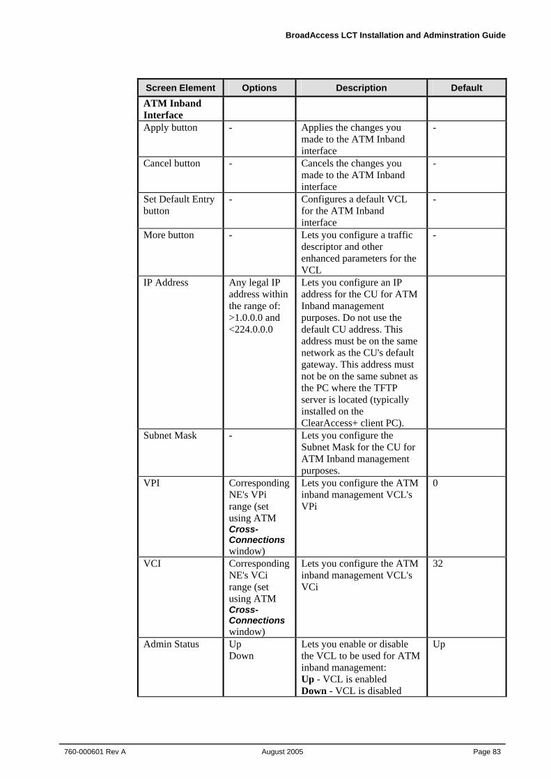
BroadAccess LCT Installation and Adminstration Guide
760-000601 Rev A August 2005
Page 83
Screen Element Options Description Default ATM Inband Interface
Apply button - Applies the changes you made to the ATM Inband interface
-
Cancel button - Cancels the changes you made to the ATM Inband interface
-
Set Default Entry button
- Configures a default VCL for the ATM Inband interface
-
More button - Lets you configure a traffic descriptor and other enhanced parameters for the VCL
-
IP Address Any legal IP address within the range of: >1.0.0.0 and <224.0.0.0
Lets you configure an IP address for the CU for ATM Inband management purposes. Do not use the default CU address. This address must be on the same network as the CU's default gateway. This address must not be on the same subnet as the PC where the TFTP server is located (typically installed on the ClearAccess+ client PC).
Subnet Mask - Lets you configure the Subnet Mask for the CU for ATM Inband management purposes.
VPI Corresponding NE's VPi range (set using ATM Cross-Connections window)
Lets you configure the ATM inband management VCL's VPi
0
VCI Corresponding NE's VCi range (set using ATM Cross-Connections window)
Lets you configure the ATM inband management VCL's VCi
32
Admin Status Up Down
Lets you enable or disable the VCL to be used for ATM inband management: Up - VCL is enabled Down - VCL is disabled
Up
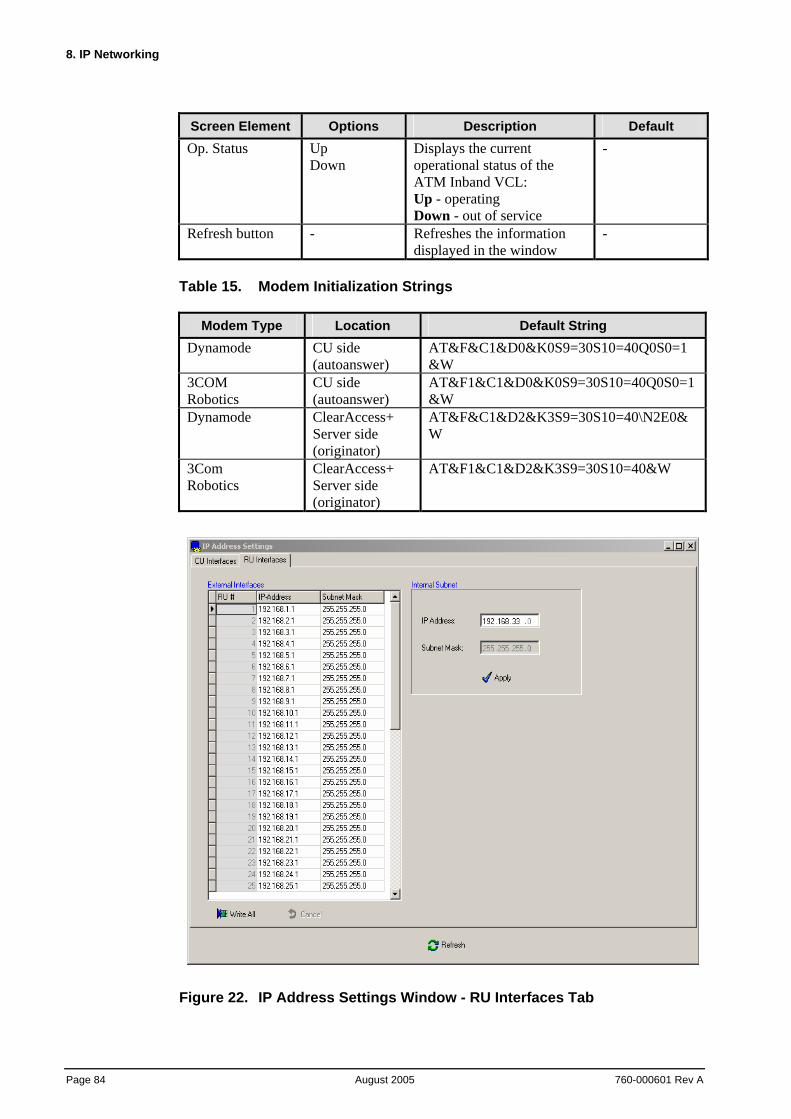
8. IP Networking
Page 84 August 2005
760-000601 Rev A
Screen Element Options Description Default Op. Status Up
Down Displays the current operational status of the ATM Inband VCL: Up - operating Down - out of service
-
Refresh button - Refreshes the information displayed in the window
-
Table 15. Modem Initialization Strings
Modem Type Location Default String Dynamode CU side
(autoanswer) AT&F&C1&D0&K0S9=30S10=40Q0S0=1&W
3COM Robotics
CU side (autoanswer)
AT&F1&C1&D0&K0S9=30S10=40Q0S0=1&W
Dynamode ClearAccess+ Server side (originator)
AT&F&C1&D2&K3S9=30S10=40\N2E0&W
3Com Robotics
ClearAccess+ Server side (originator)
AT&F1&C1&D2&K3S9=30S10=40&W
Figure 22. IP Address Settings Window - RU Interfaces Tab
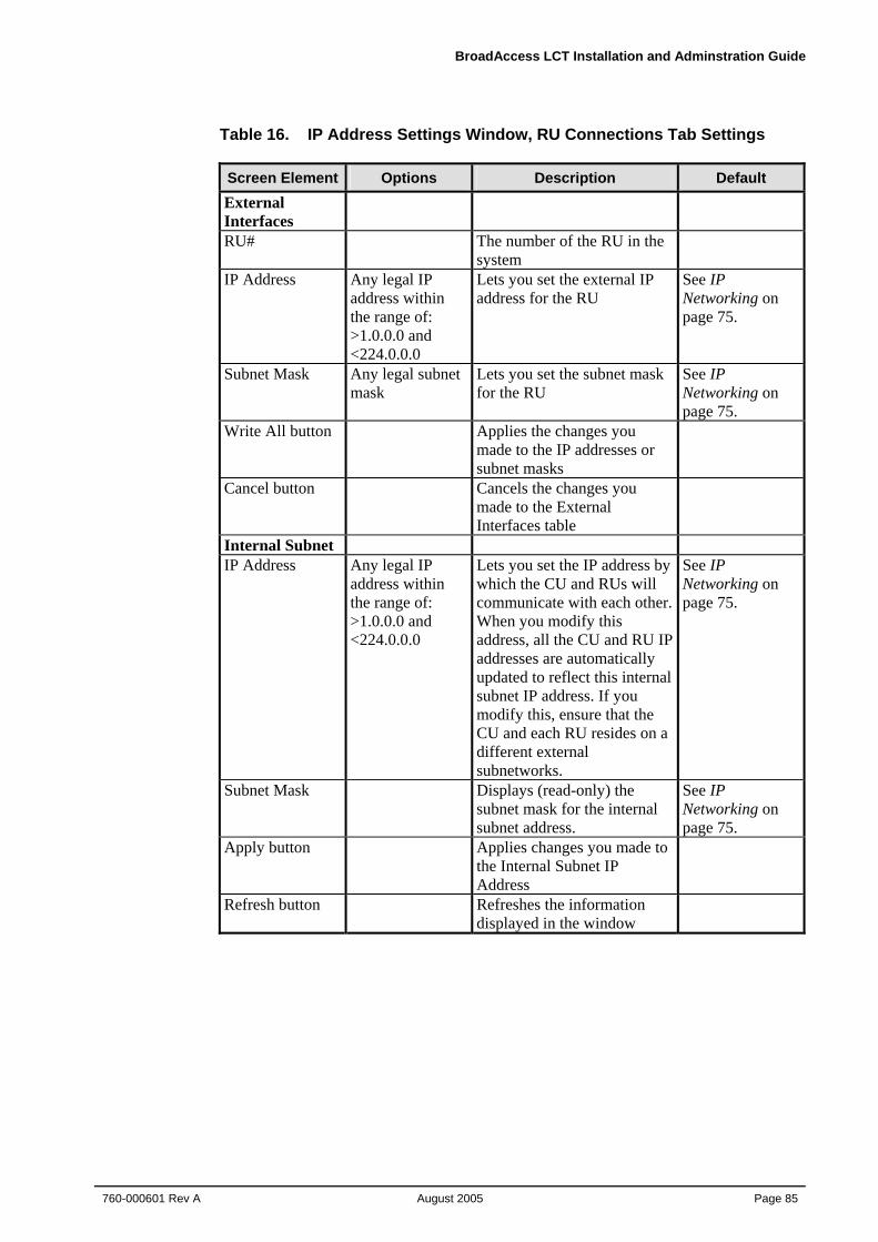
BroadAccess LCT Installation and Adminstration Guide
760-000601 Rev A August 2005
Page 85
Table 16. IP Address Settings Window, RU Connections Tab Settings Screen Element Options Description Default External Interfaces
RU# The number of the RU in the system
IP Address Any legal IP address within the range of: >1.0.0.0 and <224.0.0.0
Lets you set the external IP address for the RU
See IP Networking on page 75.
Subnet Mask Any legal subnet mask
Lets you set the subnet mask for the RU
See IP Networking on page 75.
Write All button Applies the changes you made to the IP addresses or subnet masks
Cancel button Cancels the changes you made to the External Interfaces table
Internal Subnet IP Address Any legal IP
address within the range of: >1.0.0.0 and <224.0.0.0
Lets you set the IP address by which the CU and RUs will communicate with each other. When you modify this address, all the CU and RU IP addresses are automatically updated to reflect this internal subnet IP address. If you modify this, ensure that the CU and each RU resides on a different external subnetworks.
See IP Networking on page 75.
Subnet Mask Displays (read-only) the subnet mask for the internal subnet address.
See IP Networking on page 75.
Apply button Applies changes you made to the Internal Subnet IP Address
Refresh button Refreshes the information displayed in the window
8. IP Networking
Page 86 August 2005
760-000601 Rev A
8.2. Configuring SNMP Communities Settings When BroadAccess systems are managed by ClearAccess+, SNMP Communities settings can be used as a means of restricting unwanted access to the Network Elements and the server in the ClearAccess+ network. All BroadAccess NEs are pre-configured with default SNMP Community values, and usually, there is no need to modify them. However, if you do decide to modify them, this must be done both in the BroadAccess system itself, and in the NE properties configured in the ClearAccess+ client application (see the ClearAccess+ User Guide or help system for more information).
SNMP Communities settings are modified by connecting to the BroadAccess system with Microsoft HyperTerminal.
To change a BroadAccess system's SNMP Communities settings, using Microsoft Windows HyperTerminal:
1. Connect your computer to the connector marked "COM1" on the CU backplane, using a standard RS-232 cable (see the figure COM1 Port Location).
2. In Microsoft Windows, open the Start menu and select the Run option. The Run dialog box appears.
3. In the Open field, type: Hypertrm.exe. Click OK. The New Connection HyperTerminal window appears.
4. Click the New button. The Connection Description dialog box appears.
5. Type a name for the Connection and click OK. The Connect to... dialog box appears.
6. From the Connect dialog box, using the drop-down list, select the serial port you are connecting to. Click OK.
7. Click the Properties button. The Properties dialog box appears.
8. Set the port settings as follows: Bits per second:19200, Data bits:8, Parity:None, Stop bits:1, Flow control:None. Click OK.
9. In the HyperTerminal, press <Enter> continuously or press it for a few seconds, until a request for a password appears.
10. Type "PASS02" and press <Enter>. The Welcome to BA40 LCT MAIN MENU appears.
11. To change SNMP Communication settings, type 2 and press <Enter>. Follow the on-screen instructions to change Get, Set and Trap values.
12. To exit, type 4 and press <Enter>.
BroadAccess LCT Installation and Adminstration Guide
760-000601 Rev A August 2005
Page 87
8.3. Configuring the System's ATM Inband Interface Note: See IP Networking on page 75 and Configuring IP Addresses on page
78 for more detailed information about planning the IP addresses in your network, and detailed information about each parameter in the IP Address Settings window.
Caution: If you set the ATM Inband status to Down, you may not be able to remotely reestablish ATM Inband management of the NE.
To configure the system's ATM Inband interface:
1. Point to a BroadAccess NE and right-click. The shortcut menu is displayed.
2. Select the NE Operation option. The NE Operation window appears.
3. From the NE Operation Menu Bar, select the Configuration option and then the IP Address Settings option. The IP Address Settings window appears.
4. On the CU Interfaces tab, in the ATM Inband Interface box, click on the IP Address, Subnet Mask, VPI and VCI cells in the table and enter the required parameters.
5. Click the More button. Modify the parameters as required, Apply and close when finished.
6. Click the Admin Status cell and set the status to Up.
8.4. Configuring the System's PPP Interface Note: See IP Networking on page 75 and Configuring IP Addresses on page
78 for more detailed information about planning the IP addresses in your network, and detailed information about each parameter in the IP Address Settings window.
Note: See the Configuration section of the ClearAccess+ Installation and Administration Guide or ClearAccess+ online help system for more information about managing NEs using the PSTN network.
To configure the system's PPP interface:
1. Point to a BroadAccess NE and right-click. The shortcut menu is displayed.
2. Select the NE Operation option. The NE Operation window appears.
3. From the NE Operation Menu Bar, select the Configuration option and then the IP Address Settings option. The IP Address Settings window appears.
4. On the CU Interfaces tab, in the PPP Interfaces box, enter the Local IP Address, the Remote IP Address, the Modem Mode and the Modem Initialization String.
8. IP Networking
Page 88 August 2005
760-000601 Rev A
5. Click the Apply button.
8.5. Changing a CU's Network IP Address Using HyperTerminal
The CU cage is supplied with a default external IP Address, which is used for communication between the NE and ClearAccess+. To change the CU's external IP address, use the NE Operation window (see Configuring IP Addresses on page 78, for more information). You can also use Microsoft Windows HyperTerminal application, or other software, as described below.
For more information about IP Networking and default IP addresses, see IP Networking on page 75.
To change a CU's Network IP Address using Microsoft Windows HyperTerminal:
1. Connect your computer to the connector marked "COM1" on the CU backplane, using a standard RS-232 cable (see the figure COM1 Port Location).
2. In Microsoft Windows, open the Start menu and select the Run option. The Run dialog box appears.
3. In the Open field, type: Hypertrm.exe. Click OK. The New Connection HyperTerminal window appears.
4. Click the New button. The Connection Description dialog box appears.
5. Type a name for the connection and click OK. The Connect to... dialog box appears.
6. From the Connect dialog box, using the drop-down list, select the serial port you are connecting to. Click OK.
7. Click the Properties button. The Properties dialog box appears.
8. Set the port settings as follows: Bits per second:19200, Data bits:8, Parity:None, Stop bits:1, Flow control:None. Click OK.
9. In the HyperTerminal, press <Enter> continuously or press it for a few seconds, until a request for a password appears.
10. Type "PASS02" and press <Enter>. The Welcome to BA40 LCT MAIN MENU appears.
11. To change the default IP address, type 1 and press <Enter>. The current IP address on LAN, LAN interface's subnet mask and IP address gateway appear followed by " Do you want to change LAN interface?" .
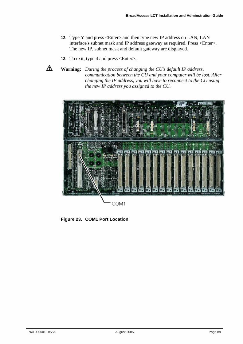
BroadAccess LCT Installation and Adminstration Guide
760-000601 Rev A August 2005
Page 89
12. Type Y and press <Enter> and then type new IP address on LAN, LAN interface's subnet mask and IP address gateway as required. Press <Enter>. The new IP, subnet mask and default gateway are displayed.
13. To exit, type 4 and press <Enter>.
Warning: During the process of changing the CU's default IP address, communication between the CU and your computer will be lost. After changing the IP address, you will have to reconnect to the CU using the new IP address you assigned to the CU.
Figure 23. COM1 Port Location

BroadAccess LCT Installation and Adminstration Guide
760-000601 Rev A August 2005
Page 91
9. Using the Telnet Command Line Interface
When communication is down between the CU and RU, you can perform limited management tasks by connecting a computer directly to the Ethernet connector on the RU backplane. Using a Telnet session (Telnet is provided as part of the Windows operating system), you can view alarms relating to the RU, inventory data for the RU and can perform some software download and swap procedures on the RU's STM and CP cards.
In order to facilitate the Telnet session between the RU and your computer, you have to configure your PC's Ethernet interface with a static IP address which is on the same network as the RU. See IP Networking on page 75 for more information about default RU IP addresses. See Windows' documentation or help system for information about changing your computer's Ethernet port IP address.
If you want to download software to the RU from your PC, you must ensure that it has TFTP client/server software installed on it. If your computer has LCT installed on it, TFTP applications are already installed on your computer.
Summary of procedures required for connecting to an RU using LCT Telnet:
1. Configure your computer with an IP address on the same LAN as the RU.
2. If you want to perform software download and you are not using a computer with LCT installed on it, ensure that TFTP software is installed on it.
3. Connect your computer's Ethernet connector to the RU's backplane COM3 Ethernet connector.
4. Open a Telnet session, using the RU's IP Address to connect to the RU (for instructions, see Opening the Telnet Session with the RU on page 91).
5. Enter the password (PASS01 for Alarms and Inventory functions only; PASS02 for Alarms, Inventory and Software Download functions) and then commence your management activities.
Note: If communication is detected between the RU and the CU, access using Telnet will not be allowed by the system. In this case, you can connect to the RU using the LCT GUI.
9.1. Opening the Telnet Session with the RU Opening the Telnet session with the RU:
1. Click the Windows Start button, select the Run option, type telnet and press <Enter>. You can also type telnet at the command prompt.
9. Using the Telnet Command Line Interface
Page 92 August 2005
760-000601 Rev A
2. Type open and press <Enter>.
3. Enter the RU's IP address and press <Enter>.
4. Enter the password (PASS01 for alarms and inventory or PASS02 for all functions).
5. The management interface with the system opens.
9.2. Using the Command Line Interface The main menu of the LCT, when using Telnet, includes the following options:
1. Alarms
2. Inventory
3. Software Download
4. Exit
Submenus are accessed via the main menu.
The LCT Telnet Command Line Interface is operated using the keyboard, as follows:
• to select a menu option, type the corresponding number and press <Enter>
• to exit a menu and return to the previous menu, press <Esc> or type the number corresponding to the Exit option and press <Enter>
• when the system asks you to provide values for a number of parameters, you cannot proceed to the next step until you have provided all the required values
9.3. Viewing RU Alarms via Telnet The LCT Telnet CLI lets you view a subset of BroadAccess alarms; only those relevant to restoring RU communication with the CU are provided. For more information about alarm messages and troubleshooting procedures, see the BroadAccess Configuration and Maintenance Guide in the Service Manual, or the NE Operation help system.
To view alarms:
1. Connect to the system using Telnet, as explained in Using the Telnet Command Line Interface on page 91.
2. Type 1 and press <Enter>. If no alarms are active, the message "No Current Alarms" is displayed. If alarms are active, they are displayed on the screen, in groups of 20 alarm messages.
BroadAccess LCT Installation and Adminstration Guide
760-000601 Rev A August 2005
Page 93
9.4. Viewing RU Inventory Information via Telnet The LCT Telnet CLI lets you view inventory information for the RU which it is managing. You can view the following information for each card installed in the RU:
• Component (options include: Motherboard, Card Type, Piggy, Cage)
• Software version
• Hardware version
• Part number
• Serial number
To view RU inventory information:
1. Connect to the system using Telnet, as explained in Using the Telnet Command Line Interface on page 91.
2. Type 2 and press <Enter>.
3. Follow the instructions on the screen.
Note: If a card slot is empty, the message "Empty Slot" is displayed.
9.5. Downloading and Swapping Software via Telnet You can download and swap software to the STM or CPT cards installed in the RU, and view download and swap status using LCT Telnet. Only a limited range of functionality is available, and it is recommended to perform download using Telnet only in urgent circumstances. You can only download software to all cards of the same type in the RU; you cannot download software to a specific card. For a full range of download and swap features, including software version control and many other advanced features, it is recommended, when possible, to perform software download and swap using ClearAccess+ or LCT, using the NE Operation window. For more information, see "System Software Management" in the BroadAccess Configuration and Maintenance Guide in the Service Manual, or the NE Operation help system.
Only LCT Telnet users with software download privileges can perform download procedures (see Using the Telnet Command Line Interface on page 91 for more information).
Before commencing software download, ensure that the TFTP server application on your computer is running, and that you have saved the software files to be downloaded in the root directory of the TFTP server.
9. Using the Telnet Command Line Interface
Page 94 August 2005
760-000601 Rev A
On a computer where LCT is installed, the TFPT server application is launched automatically when you start up your computer (a shortcut appears in the Windows Start|Programs|Startup menu), however it is launched with the server stopped. To start the server itself, open the TFTPD's window and from the main menu, select the TFTPD|Start option.
To get status information about a card (can be performed in all software download and swap states):
1. Connect to the system using Telnet, as explained in Using the Telnet Command Line Interface on page 91.
2. Type 3 and press <Enter>. The main Software Download menu appears.
3. Type 1 (Get Status) and press <Enter>. A list of options appears.
4. Type the number corresponding to the item for which you want information, and press <Enter>.
To download software to a card:
1. Connect to the system using Telnet, as explained in Using the Telnet Command Line Interface on page 91.
2. Type 3 and press <Enter>. The main Software Download menu appears.
3. Type 2 (Setting) and press <Enter>. A list of options appears.
4. Type 2 (param setting) and press <Enter>. A list of options appears.
5. Type 1 (Card type) and press <Enter>. Enter the number corresponding to the card type you require, and press <Enter>..
6. Type 2 (Server IP Address) and press <Enter>. Type the IP Address of the TFTP server where the card software files are saved, and press <Enter>.
7. Type 3 (File Name) and press <Enter>. Type the name of the software file which you want to download to the card, and press <Enter>.
8. Type 4 (Software Version) and press <Enter>. Enter the software version number and press <Enter>.
9. Type 5 (Send Parameters and Exit) and press <Enter>. The Setting menu is displayed.
10. Type 3 (Start TFTP) and press <Enter>. The TFTP server commences transferring the file to the RU.
11. After a few minutes, check the status of the TFTP file transfer by returning to the main Software Download menu and typing 1 (Get Status). When the system indicates that transfer is complete, proceed to the next step.
12. Return to the main software download menu. Type 2 (Setting) and press <Enter>.
BroadAccess LCT Installation and Adminstration Guide
760-000601 Rev A August 2005
Page 95
13. Type 4 (Start Download) and press <Enter>.
14. After several minutes, you can check whether the download to the cards was successful by returning to the main Software Download menu and typing 4 (Get Success Cards). If download was successful, the message "Download Completed" is displayed.
To swap card control to the software in the inactive bank (usually to the software you downloaded to the cards):
1. Connect to the system using Telnet, as explained in Using the Telnet Command Line Interface on page 91.
2. Type 3 and press <Enter>. The main Software Download menu appears.
3. Type 3 (Set Swap) and press <Enter>. A list of options appears.
4. Type 1 (Start Swap) and press <Enter>.
5. Enter the parameters requested by the system. There is a minimum 10 minute delay before the actual swap process commences.
6. After several minutes, you can check whether the swap was successful by returning to the main Software Download menu and typing 6 (Get Swap).
To view software versions saved in the banks of a specific card (active and inactive banks):
1. Connect to the system using Telnet, as explained in Using the Telnet Command Line Interface on page 91.
2. Type 3 and press <Enter>. The main Software Download menu appears.
3. Type 5 (Get SW Version) and press <Enter>.
4. Follow the instructions on the screen (enter the parameters requested by the system).

BroadAccess LCT Installation and Adminstration Guide
760-000601 Rev A August 2005
Page 97
10. Index A
Adding, Deleting and Modifying LCT Users' Properties • 69
Adding, Deleting and Modifying Users' Properties • 64
ATM • 10
B
BroadAccess System Overview • 1
Buttons, Toolbar • 46
C
Changing a CU's Network IP Address Using HyperTerminal • 88
Changing LCT User Passwords • 73
Changing User Passwords • 67
CLI • 10
Command Line Interface • 91
Commands, Menu • 46
Configuration Required for Management using Dial-Up Connections • 21
Configuring IP Addresses • 78
Configuring LCT User Properties • 68
Configuring SNMP Communities Settings • 86
Configuring the Dial-up Connections for each NE • 26
Configuring the System's ATM Inband Interface • 87
Configuring the System's PPP Interface • 87
Configuring User Properties • 64
Connecting to an NE • 39
Conventions and Terminology • 6
Creating and Configuring a BroadAccess 40 Network Element • 41
Creating Reports • 51
10. Index
Page 98 August 2005
760-000601 Rev A
CU • 10
D
DB • 10
DBA • 10
Downloading and Swapping Software via Telnet • 93
E
EMS • 10
G
GUI • 11
H
Hardware Requirements • 5
Hiding Columns in Tables • 51
Hiding Columns of Data in Tables • 51
I
Installation Error Messages • 36
Installing
LCT • 7
Null Modem • 15
Oracle • 7
Installing and Configuring the Null Modem • 15
Installing LCT • 7
Introduction • 5
Inventory, Viewing • 93
IP • 11
IP Address • 41, 88
IP Networking • 75
L
LAN • 11

BroadAccess LCT Installation and Adminstration Guide
760-000601 Rev A August 2005
Page 99
LCT • 11
LCT Users, Defining • 68
LCT Work Area • 46
LE • 11
List of Acronyms and Abbreviations Used in this Guide • 10
Local Craft Terminal Overview • 3
Logging on and Connecting to the BroadAccess NE • 39
M
Menu Bar and Toolbar • 46
N
NE • 11
Null Modem • 15
O
Opening an LCT Session • 39
Opening the Telnet Session with the RU • 91
Oracle
Installing • 7
Removing a Single Oracle_Home • 31
Uninstalling • 28
Overview, System • 1
P
Passwords
Changing LCT User • 73
Changing User • 67
PC • 11
PSTN • 11
R
Related Publications • 6
10. Index
Page 100 August 2005
760-000601 Rev A
Removing a Single Oracle Home • 31
Reports • 51
Requirements, System
Hardware • 5
Software • 5
Restoring Columns in Tables • 51
RU • 11
S
Security Levels, Default • 63
Security Management • 63
SHDSL • 11
SNMP • 11
Software Download • 93
Software Requirements • 5
System Requirements • 5
T
Telnet • 91
TFTP • 11
Toolbar • 46
U
Unhiding Columns in Tables • 51
Uninstalling
LCT • 27
Oracle • 28
Removing a Single Oracle_Home • 31
Uninstalling LCT • 27
Uninstalling Oracle • 28
Upgrading LCT • 27
BroadAccess LCT Installation and Adminstration Guide
760-000601 Rev A August 2005
Page 101
User Interface • 45
Users, Defining • 64
Users, LCT, Defining • 68
Using the Advanced Database Filter • 52
Using the Command Line Interface • 92
Using the Report Designer • 55
Using the Telnet Command Line Interface • 91
V
Viewing RU Alarms via Telnet • 92
Viewing RU Inventory Information via Telnet • 93