Embed Size (px)
Citation preview

Hamid Shoaee
EPICS Collaboration Meeting, APS [email protected]
June 13, 2006
LCLS Control System
Hamid ShoaeeFor the
LCLS Controls Group
Control Engineers
Store

Hamid Shoaee
EPICS Collaboration Meeting, APS [email protected]
June 13, 2006
Linac Coherent Light Source (LCLS) at SLACLinac Coherent Light Source (LCLS) at SLAC
InjectorInjector11--km Linackm Linac
ee--BeamBeamTransportTransport
UndulatorUndulator
Near Experiment HallNear Experiment Hall
FarFarExperimentExperimentHall (underground)Hall (underground)

Hamid Shoaee
EPICS Collaboration Meeting, APS [email protected]
June 13, 2006
PORCU
PINE CATHODE
HOLDE
R
UHV A
LL METAL
GATE VALVES
SPOOLS FRO
M VALVE
SEAL
LONG B
ELLOWS
ASSEM
BLY
TREATMEN
T CHAM
BER
VACUU
M PUMPS
Transverse RF deflectorTransverse RF deflector
RF GunRF Gun
gun gun spectrometerspectrometer
main SLAC Linac main SLAC Linac
injector spectrometerinjector spectrometer
Injector LayoutInjector LayoutInjector LayoutL0a RF sectionL0a RF section
L0b RF sectionL0b RF section
L1 RF sectionL1 RF section(21(21--1b)1b)
sector 20sector 20 sector 21sector 21
6 MeV6 MeV
62 MeV62 MeV
135 MeV135 MeV

Hamid Shoaee
EPICS Collaboration Meeting, APS [email protected]
June 13, 2006
RF PhotoRF Photo--Cathode GunCathode Gun
ee−−−−−−−−
ee−−−−−−−−
YAG screensYAG screenssolenoidsolenoid
RF gunRF guncathodecathode
UV laserUV laser
spec. dipolespec. dipole
QQ = 1 = 1 nCnC
ff = 120 Hz= 120 Hz
GG = 120 MV/m= 120 MV/m
γεγεx,yx,y = 1 = 1 µµmm
∆∆ττ = 10 ps= 10 ps
II = 100 A= 100 A
EE = 6 MeV= 6 MeV

Hamid Shoaee
EPICS Collaboration Meeting, APS [email protected]
June 13, 2006
LCLSLCLS AcceleratorAccelerator
SLAC linac tunnelSLAC linac tunnel research yardresearch yard
LinacLinac --00L L =6 m=6 m
LinacLinac --11L L ≈≈9 m9 m
ϕϕrf rf ≈≈ −−2525°°
LinacLinac --22L L ≈≈330 m330 mϕϕrf rf ≈≈ −−4141°°
LinacLinac --33L L ≈≈550 m550 mϕϕrf rf ≈≈ 00°°
BC1BC1L L ≈≈6 m6 m
RR5656≈≈ −−39 mm39 mm
BC2BC2L L ≈≈22 m22 m
RR5656≈≈ −−25 mm25 mm DL2 DL2 L L =275 m=275 mRR56 56 ≈≈ 0 0
DL1DL1L L ≈≈12 m12 mRR56 56 ≈≈0 0
undulatorundulatorL L =130 m=130 m
6 MeV6 MeVσσz z ≈≈ 0.83 mm0.83 mmσσδδ ≈≈ 0.05 %0.05 %
135 MeV135 MeVσσz z ≈≈ 0.83 mm0.83 mmσσδδ ≈≈ 0.10 %0.10 %
250 MeV250 MeVσσz z ≈≈ 0.19 mm0.19 mm
σσδδ ≈≈ 1.6 %1.6 %
4.30 GeV4.30 GeVσσz z ≈≈ 0.022 mm0.022 mm
σσδδ ≈≈ 0.71 %0.71 %
13.6 GeV13.6 GeVσσz z ≈≈ 0.022 mm0.022 mm
σσδδ ≈≈ 0.01 %0.01 %
LinacLinac --XXL L =0.6 m=0.6 m
ϕϕrfrf= = −−160160°°
21-1b,c,d
...existinglinac
L0-a,b
rfrfgungun
21-3b24-6dX
25-1a30-8c
Commission in Jan. 2007Commission in Jan. 2007 Commission in Jan. 2008Commission in Jan. 2008

Hamid Shoaee
EPICS Collaboration Meeting, APS [email protected]
June 13, 2006
MMM JJJ JJJ AAA SSS OOO NNN DDD JJJ FFF MMM AAA MMM JJJ JJJ AAA SSS OOO NNN DDD JJJ FFF MMM AAA MMM JJJ JJJ
LCLSLCLS Installation and Commissioning TimeInstallation and Commissioning Time--LineLine
DriveDrive --Laser Laser InstallInstall
DriveDrive --Laser Laser CommissioningCommissioning
Gun/Inj./BC1 Gun/Inj./BC1 CommissioningCommissioning
JuneJune20062006
Gun/Inj./BC1 Gun/Inj./BC1 InstallInstall
(8/21 (8/21 –– 1/5)1/5)
linac/BC2 linac/BC2 InstallInstall
First Spont. First Spont. LightLight
linac/BC2 linac/BC2 CommissioningCommissioning
LTU/undulator LTU/undulator CommissioningCommissioning
LTU/und. LTU/und. InstallInstall
200620062006 200720072007 200820082008
FEL Comm.FEL Comm.
undulatorundulatorhall readyhall ready
First FEL First FEL LightLight

Hamid Shoaee
EPICS Collaboration Meeting, APS [email protected]
June 13, 2006
Self-Amplified Spontaneous Emission (SASE)
These micro-bunches begin toradiate as if they were singleparticles with immense charge.The process reaches saturationwhen the micro-bunching hasgone as far as it can go.
N S NS N SN SN S N S N S N S N S
N N SS N SN SN S N S N S N S N S
An intense, highly collimated electronbeam travels through an undulatormagnet. The alternating north and southPoles of the magnet force the electronbeam to travel on an approximatelysinusoidal trajectory, emitting synchrotron
radiation as it goes.
N S NS N SN SN S N S N S N S N S
N N SS N SN SN S N S N S N S N S
The electron beam and its synchrotronradiation are so intense that the electronmotion is modified by the electromagneticfields of its own emitted synchrotronlight. Under the influence of both theundulator and its own synchrotronradiation, the electron beam begins toform micro-bunches, separated bya distance equal to the wavelength of theemitted radiation.
N S NS N SN SN S N S N S N S N S
N N SS N SN SN S N S N S N S N S

Hamid Shoaee
EPICS Collaboration Meeting, APS [email protected]
June 13, 2006
Prototype LCLS UndulatorPrototype LCLS Undulator
8004000-400-800Z(mm)
-2.0
-1.0
0.0
1.0
2.0
Ho
rizo
nta
l Tra
ject
ory
(µ)
Horizontal Trajectory
Micro
ns

Hamid Shoaee
EPICS Collaboration Meeting, APS [email protected]
June 13, 2006
Free-Electron Lasers
1977- First operation of a free-electron laser at Stanford University
Deacon, et al. PRL v. 38, no.16, pp. 892-894http://accelconf.web.cern.ch/accelconf/p73/PDF/PAC1973_0980.PDF
Today22 free-electron lasers operating worldwide19 FELs proposed or in construction
http://sbfel3.ucsb.edu/www/vl_fel.html

Hamid Shoaee
EPICS Collaboration Meeting, APS [email protected]
June 13, 2006
Looking Ahead – LCLS development
LCLSLUSILUSI
NNSALUSI
SpringSpring --88European XFELEuropean XFEL

Hamid Shoaee
EPICS Collaboration Meeting, APS [email protected]
June 13, 2006
1.6 End Station Systems
1.5 X-Ray Transport/Optics/Diagnostics
Photon Beam Systems

Hamid Shoaee
EPICS Collaboration Meeting, APS [email protected]
June 13, 2006
Controls responsibilities cover a large range of activities
The group’s responsibilities range from cable trays to end station detector control and DAQCable plant designGlobal control infrastructureA rich set of beam diagnostics and instrumentationOperations software and control room toolsHigh level applicationsFeedback systemsSafety systemsExperimental end station control and data management

Hamid Shoaee
EPICS Collaboration Meeting, APS [email protected]
June 13, 2006
Injector Tunnel InstallationInjector Tunnel Installation

Hamid Shoaee
EPICS Collaboration Meeting, APS [email protected]
June 13, 2006
LCLS UNDULATOR SYSTEM
33 Undulators33 Quadrupoles/Correctors
EM air-cooled10 Long breaks22 Short BreaksSupports with movers
5 DOF plus horizontal sliderVacuum System
Al on SS (316LN)“Rectangular” Cross Section
33 rf Beam Position Monitors33 Beam Finder WiresWire Position MonitorHydro static level system

Hamid Shoaee
EPICS Collaboration Meeting, APS [email protected]
June 13, 2006
1st Article Undulator Received1st Article Undulator Received
One each received One each received from the two vendorsfrom the two vendors
Initial Measurements Initial Measurements and Tuningand Tuning
xx & & yy trajectories well trajectories well under the 2under the 2--micron limitmicron limit
RMS phase error well RMS phase error well under the 10under the 10--deg. limitdeg. limit

Hamid Shoaee
EPICS Collaboration Meeting, APS [email protected]
June 13, 2006
RF BPM for UndulatorRF BPM for UndulatorFirst Prototype CompletedFirst Prototype CompletedBench MeasurementsBench Measurements
No surprisesNo surprises
Installation for Beam TestInstallation for Beam TestPlanned to install in ITS by Planned to install in ITS by end of monthend of month
3 BPM Test3 BPM TestPlanned installation mid to Planned installation mid to late summerlate summer
ScheduleScheduleStill considered an Still considered an undulatorundulatorsystem critical path itemsystem critical path item

Hamid Shoaee
EPICS Collaboration Meeting, APS [email protected]
June 13, 2006
First Beam Observed in Undulator Cavity BPM

Hamid Shoaee
EPICS Collaboration Meeting, APS [email protected]
June 13, 2006
LCLS Presentations at this Meeting
LCLS Timing and LLRF on RTEMS Dale Kotturi
LCLS Timing Stephanie Allison
LCLS Magnet Support Debbie Rogind
LCLS network and support planning Terri Lahey
LCLS Undulator Positioning Control System Shifu Xu
Experience installing and gettingstarted with XAL Sergei Chevtsov

Hamid Shoaee
EPICS Collaboration Meeting, APS [email protected]
June 13, 2006
Vacuum System Controls Hardware
Ion pumpsGamma Digitel Multiple Pump Controller (MPC)
Terminal server: RS232 connections to vacuum controllers
Digi PortServer TS 16
Hot filament and Convectron gauges
Granville-Phillips 307 gauge controller
Cold cathode and Pirani gaugesMKS 937A gauge controller
Valve control, interlock logic, interface to global control system
Allen-Bradley ControlLogix Programmable Logic Controller (PLC)
FunctionHardware

Hamid Shoaee
EPICS Collaboration Meeting, APS [email protected]
June 13, 2006
Vacuum System Block Diagram

Hamid Shoaee
EPICS Collaboration Meeting, APS [email protected]
June 13, 2006
Location of Main Linac DiagnosticsLocation of Main Linac Diagnostics
...existing linac...existing linac
L0L0
rfrfgungun
L3L3L1L1 XX L2L2
γεγεxx,,yy γεγεxx,,yy γεγεxx,,yy γεγεxx,,yy
γεγεxx,,yy
σσEE σσEE σσEEσσEE
5+ energy spread meas. stations (optimized with small 5+ energy spread meas. stations (optimized with small ββ))5+ emittance meas. stations designed into optics (5+ emittance meas. stations designed into optics (∆∆ψψxx,,yy))BPMs at or near most quadrupoles and in each bend syst.BPMs at or near most quadrupoles and in each bend syst.RF deflectors for slice RF deflectors for slice εε and and σσEE measurements (L0 & L3)measurements (L0 & L3)
σσEE
⟨⟨EE⟩⟩ ⟨⟨EE⟩⟩⟨⟨EE⟩⟩⟨⟨EE⟩⟩ ⟨⟨EE⟩⟩
TT--cavcav..
TT--cavcav..
PORCU
PINE CATHODE
HOLDE
R
UHV A
LL METAL
GATE VALVES
SPOOLS FRO
M VALVE
SEAL
LONG B
ELLOWS
ASSEM
BLY
TREATMEN
T CHAM
BER
VACUU
M PUMPS
PORCU
PINE CATHODE
HOLDE
R
UHV A
LL METAL
GATE VALVES
SPOOLS FRO
M VALVE
SEAL
LONG B
ELLOWS
ASSEM
BLY
TREATMEN
T CHAM
BER
VACUU
M PUMPS
Transverse RF deflectorTransverse RF deflector
RF GunRF Gun
gun gun spectrometerspectrometer
YAG screenYAG screenYAG screenYAG screen
YAGYAGscreenscreen
YAG screenYAG screen
OTR screen OTR screen & & wirewire
OTR screen & OTR screen & wirewire
OTR screen & OTR screen & wirewire
YAG screenYAG screen YAG & YAG & OTROTR
OTR screen OTR screen & & wirewire
YAG screenYAG screen
main SLAC Linac main SLAC Linac
Gun/Injector DiagnosticsGun/Injector Diagnostics
injector spectrometerinjector spectrometer
trajectory (trajectory (BPMsBPMs))emittance (+ slice)emittance (+ slice)energy spread (+ slice)energy spread (+ slice)bunch length (+ dist.)bunch length (+ dist.)charge (+ dark current)charge (+ dark current)

Hamid Shoaee
EPICS Collaboration Meeting, APS [email protected]
June 13, 2006
LCLS Timing System
The LCLS timing system is used to transmit a fiducial 360 Hz signal to all triggered devices in LCLSSystem requirements include
receiving 128 bit PNET data at 360 Hz; appending additional information; operate at 120 Hz
The component parts are known: PNET VME receiver, EVG-200 and EVR-200The interfaces are being defined

Hamid Shoaee
EPICS Collaboration Meeting, APS [email protected]
June 13, 2006
PNET
SLCControlSystem
119MHz RF Clock
Trigger Delays, Event Codes per Output Channel
MeasIOCs
EVR
ADC
Actuator IOCs
Timing System
IOCAccEVG
PNET
Timing Pattern,Timestamp, Event Codes
DAC
EVR
EVGFanOut
Acc Channel Access
Beam Rate, Beam Path
Trigger Trigger
360Hz Fiducial
IOCExpEVG
EVGFanOut
To Exp EVRs
MPS

Hamid Shoaee
EPICS Collaboration Meeting, APS [email protected]
June 13, 2006
Timing Requirements
20 psLong term stability
8 nsDifferential error, location to location
2 ps rmsMax timing jitter w.r.t. clock
20 psFine step size
>1 secDelay range
8.4 ns ± 20 psCoarse step size
20 psClock precision
119 MHzClock frequency
360 Hz Maximum trigger rate

Hamid Shoaee
EPICS Collaboration Meeting, APS [email protected]
June 13, 2006
Event/Timing System StatusStatus
Testing with new EVG/EVR 200 series VME and PMC modulesAdapted EVG/EVR driver/device support to send data buffers and run on RTEMSStephanie Allison and Mark Crane coming up to speedTest stands for HW folks not yet readyPMC-EVR driver not yet readyRack/cable design for injector/BC1 and procurement well underwayTight schedule
Tasks:Finish PMC-EVR driver and testEVG sequence RAM programming at 360 HzEVG rules and algorithm definition for January commissioningAdd support for EVR timing pattern data recordsJitter testingInterface with other subsystems needs reviewCommissioning test plan

Hamid Shoaee
EPICS Collaboration Meeting, APS [email protected]
June 13, 2006
Motion control & Image acquisition
The injection laser stabilization control system includes up to 3 feedback loops. Each loop includes 2 mirrors. Each mirror has two actuators and one camera.
The IOC should read back the image from camera, figure out centroid, multiple pre-calculated matrix and apply the correction to the actuators.Whole loop should be about 1 Hz. Camera should be synced to 120Hz.

Hamid Shoaee
EPICS Collaboration Meeting, APS [email protected]
June 13, 2006
Introduction
Actuator A1
Camera A
Laser
Actuator A2
Actuator B1
Actuator B2
Camera B
Hamid Shoaee
EPICS Collaboration Meeting, APS [email protected]
June 13, 2006
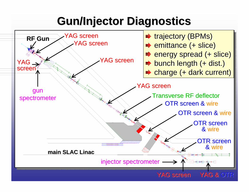
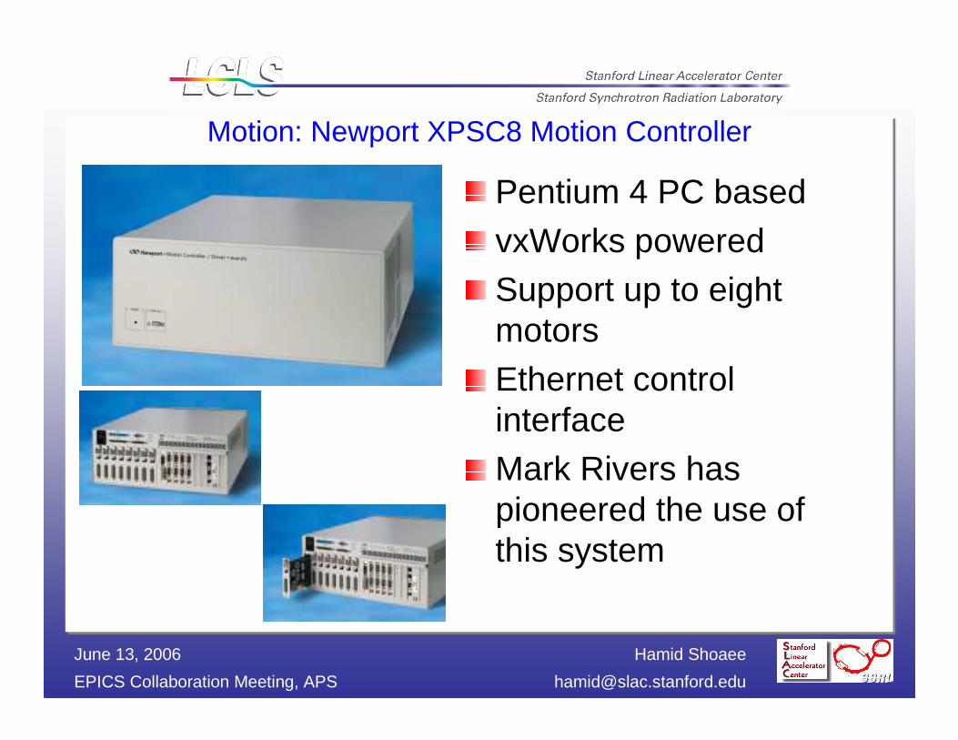
Motion: Newport XPSC8 Motion Controller
Pentium 4 PC based
vxWorks poweredSupport up to eight motors
Ethernet control interfaceMark Rivers has pioneered the use of this system

Hamid Shoaee
EPICS Collaboration Meeting, APS [email protected]
June 13, 2006
Motion: Newport CMA-12CCCL actuator
Travel range: 12.5 mmResolution: 0.2µmEncoder: YesBi-Direction repeatability: 3µmSpeed: 50~400 µm/SLoad Capacity: 90NCompatible with XPSC8

Hamid Shoaee
EPICS Collaboration Meeting, APS [email protected]
June 13, 2006
Image Acquisition: PULNiX TM-6710CL camera
CCD: 1/2”Shutter: Full FrameUV option: YesResolution: 648x484Progressive: YesExternal Trigger: YesFull scan: 120HzAnalog Output: YesCameralink: Yes

Hamid Shoaee
EPICS Collaboration Meeting, APS [email protected]
June 13, 2006
Image Acquisition: Cameralink interface
EDT PMC DV C-LinkCameralink compatible32bit/66MHz PCISupport up to 80MHz pixel clockOne base channel per card

Hamid Shoaee
EPICS Collaboration Meeting, APS [email protected]
June 13, 2006
EDM screen of two cameras

Hamid Shoaee
EPICS Collaboration Meeting, APS [email protected]
June 13, 2006
EDM screen of motion control

Hamid Shoaee
EPICS Collaboration Meeting, APS [email protected]
June 13, 2006
OTR/YAG system
OTR/YAG system share the PMC CameraLinkinterface but use different cameraUniqVision UP900CL-12B
½” CCD progressive scan1392 x 104012 bits per pixel15 Frames per secondFull frame shutterCameralink® interface
Cameralink® interfaceEDT PMC DC C-Link

Hamid Shoaee
EPICS Collaboration Meeting, APS [email protected]
June 13, 2006
Applications Software
The challenge is to integrate the existing control system (CAMAC) with the new equipment (VME)High Level ApplicationsFast Feedback Applications

Hamid Shoaee
EPICS Collaboration Meeting, APS [email protected]
June 13, 2006
CA Clients
Solution: SLC-Aware IOC
SCP
Ethernet (LCLSnet)
CAMAC
SLC Micro(RMX)
SLAC EthernetPS Controller
SLC net
SLC - VMS
CAServer
HL Apps
SCOR
Bulk PSPS PSBulk PS
Large PSController
MCOR
(LEBnet)
Any OS SCP
VME Crate (RTEMS)
EDM
CATCP/IP
HL Apps
DB
SLC-Aware IOC
- Mimics RMX micro; communicates via SLC message protocol; receives/updates SLC DB
EPICS Control-
- Minimal changes to SLC

Hamid Shoaee
EPICS Collaboration Meeting, APS [email protected]
June 13, 2006
High Level ApplicationsThe Legacy system will provide most High Level Applications required for Injector Commissioning
Orbit applications: such as orbit display, orbit fitting, orbit correction, bump calculations, etc
Supporting applications: such as buffered acquisition, correlation plots, configuration, on-line model
The LCLS on-line model and configuration are being entered into the Legacy system now.
The slc-aware IOC, which provides the interface between the Legacy system and the new EPICS based control, is ready for system integration.

Hamid Shoaee
EPICS Collaboration Meeting, APS [email protected]
June 13, 2006
High Level ApplicationsApplications that the Legacy system cannot provide are being prototyped in Matlab for commissioning
Emittance applicationEnergy Spread applicationBunch Length MeasurementFast Feedback
LabCA, a Matlab CA interface (Till Straumann:SLAC/SSRL), will be used to interface to IOCsAIDA, a multi-platform distributed data access server (Greg White:SLAC), will be used retrieve model parameters from the Legacy on-line model
The long term goal is to adopt the XAL packageto develop a comprehensive fast feedback facility

Hamid Shoaee
EPICS Collaboration Meeting, APS [email protected]
June 13, 2006
Fast FeedbackFast Feedbacks for Commissioning 2006 - 2007
Bunch ChargeInjector LaunchDL1 EnergyDL1 Energy + BC1 Energy + Bunch LengthTransverse Deflecting Cavity (to support Bunch Length Measurement)
Prototype in Matlab limits rate to ~1Hz.An ‘LCLS machine simulation’ IOC is being used to support the Matlab feedback prototypingThe Injector Launch Feedback will be prototyped in an EPICS IOC to support development of a long-term general feedback system design in EPICS.

Hamid Shoaee
EPICS Collaboration Meeting, APS [email protected]
June 13, 2006
Matlab Feedback Application

Hamid Shoaee
EPICS Collaboration Meeting, APS [email protected]
June 13, 2006
LCLS LCLS -- The WorldThe World ’’s First Hard Xs First Hard X --ray Laserray Laser

Hamid Shoaee
EPICS Collaboration Meeting, APS [email protected]
June 13, 2006
Femtochemistry
Nanoscale Dynamics in Condensed matter
Atomic Physics
Plasma and Warm Dense Matter
Structural Studies on SingleParticles and Biomolecules
FEL Science/Technology
Abs
orpt
ion
Res
onan
ce R
aman
t0
t1
t2t3
t4 t5
Aluminum plasma
10-4 10-2 1 10 2 10 4
classical plasma
dense plasma
high density matter
G =1
Density (g/cm-3)
G =10
G =100
t=0
t=ττττ
•SLAC-R-611
•http://www.slac.stanford.edu/cgi-wrap/getdoc/slac-r-611.pdf

Hamid Shoaee
EPICS Collaboration Meeting, APS [email protected]
June 13, 2006
The Atomic, Molecular & Optical Science The Atomic, Molecular & Optical Science (AMOS) Instrument @ LCLS(AMOS) Instrument @ LCLS
study of atoms & molecules, the basic building blocks of matter
Useful for understanding fundamental interactions of energy and matter
The people that brought you the laserRecommendation of the 1994 National
Research Council: “develop techniques to better control atoms, molecules, ions and light”

Hamid Shoaee
EPICS Collaboration Meeting, APS [email protected]
June 13, 2006
AMO Science at the LCLS
LCLS pulses:120 HzPhoton energy 800 – 8000 eVBandwidth ~0.07 – 0.03%~200 fs duration1013 – 1012 photons/pulse~1.9 mJ/pulse – up to 1018
W/cm2 (with a 1 µm2 focus)

Hamid Shoaee
EPICS Collaboration Meeting, APS [email protected]
June 13, 2006
AMO Instrument – temporally resolving
Initiate a process with an external laser & follow temporal evolution with LCLS pulse
Utilize site specificity of inner-shell probes to explore evolution of temporal sensitivityCan also use laser to impulsively align molecule(s) and investigate body-frame ionization informationForms basis of “clock” for overlap of two pulsesUse of lasers to create non-equilibrium samples (laser ablation, coulomb explosion of cluster…)

Hamid Shoaee
EPICS Collaboration Meeting, APS [email protected]
June 13, 2006
AMO Instrument – temporally resolving
Requirements:Need timing signal before LCLS pulse with ~100fs resolution – i.e. want to explore temporal envelope before & after LCLS pulseNeed high field laser – 20mJ sufficient
Want capability to create other colors:Harmonic generators to double & triple Ti:SappOPA to shift wavelength to anything in betweenWill need to control lasers/alignment optics

Hamid Shoaee
EPICS Collaboration Meeting, APS [email protected]
June 13, 2006
AMO Instrument - Layout
Instrument control issues:Many stepper motors (50-100) to align chambers, position detectors, etcHigh voltage (dozens) controlled through 0-10V analog signals (and similarly monitored)
Valves & pumps etc for vacuum systemValves & pumps for gas handling system
Hoping whole control system architecture can live in hutch (no long cable pulls)

Hamid Shoaee
EPICS Collaboration Meeting, APS [email protected]
June 13, 2006
Summary
LCLS is a rich ground for developing a comprehensive control systemThe challenges (aside from the usual time constraints) include, the breadth of responsibilities, development of new technologies, and integration of the old and the new…