Embed Size (px)
Citation preview
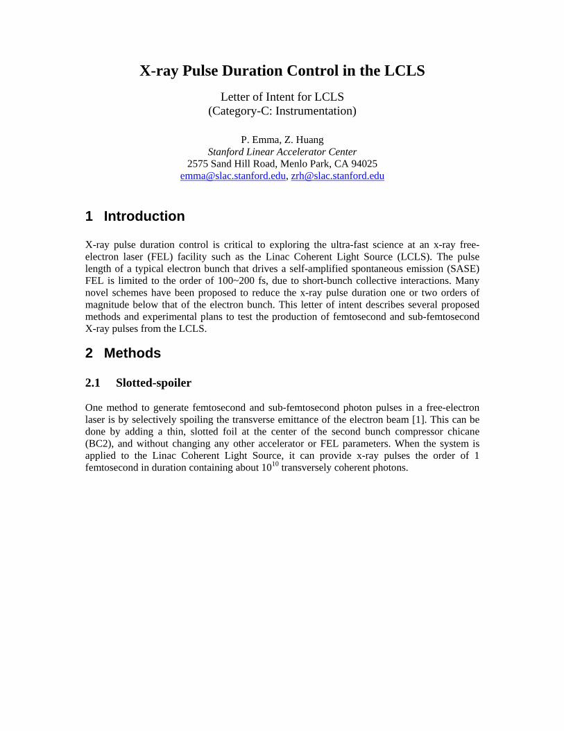
X-ray Pulse Duration Control in the LCLS Letter of Intent for LCLS
(Category-C: Instrumentation)
P. Emma, Z. Huang Stanford Linear Accelerator Center
2575 Sand Hill Road, Menlo Park, CA 94025 [email protected], [email protected]
1 Introduction X-ray pulse duration control is critical to exploring the ultra-fast science at an x-ray free-electron laser (FEL) facility such as the Linac Coherent Light Source (LCLS). The pulse length of a typical electron bunch that drives a self-amplified spontaneous emission (SASE) FEL is limited to the order of 100~200 fs, due to short-bunch collective interactions. Many novel schemes have been proposed to reduce the x-ray pulse duration one or two orders of magnitude below that of the electron bunch. This letter of intent describes several proposed methods and experimental plans to test the production of femtosecond and sub-femtosecond X-ray pulses from the LCLS.
2 Methods 2.1 Slotted-spoiler One method to generate femtosecond and sub-femtosecond photon pulses in a free-electron laser is by selectively spoiling the transverse emittance of the electron beam [1]. This can be done by adding a thin, slotted foil at the center of the second bunch compressor chicane (BC2), and without changing any other accelerator or FEL parameters. When the system is applied to the Linac Coherent Light Source, it can provide x-ray pulses the order of 1 femtosecond in duration containing about 1010 transversely coherent photons.

Emma/Huang, Pulse Duration Control in the LCLS X-ray FEL 2
x
t
e−
ee− −
xx ∝ ∝ ∆ ∆ EE//E E ∝ ∝ tt
Coulomb scattered
unspoiled e−
Coulomb scattered
2∆x
yy
a)
b)
Fig. 1: Slotted spoiler foil in 2nd bunch compressor for 1-fs X-ray pulse duration.
For the baseline LCLS parameters, a Beryllium foil with thickness of 15 µm is needed. The slot width, 2∆x in Fig. 1, is set to 250 µm, which will produce a 2-3 fsec FWHM 1.5-Å X-ray pulse with ~1010 photons and peak power of 10 GW, as shown in Fig. 2.
−100 −50 0 50 1000
2
4
6
8
10
t (fs)
Pow
er (
GW
) C
urre
nt (
kA)
Power
Current
and
Fig. 2: Electron current (blue) and 8-keV X-ray pulse (red) at the location z = 60 m in the LCLS FEL undulator, using a 250-µm slot width in the 15-µm Be slotted foil. Before this experiment proceeds, the FEL should be operating close to the baseline parameters with the system fairly well characterized, including that the electron energy jitter in the BC2 chicane is at a level of <0.2% rms for adequate stability. The foil can then be inserted into the electron beam. Beam collimators downstream of this point should be closed to nominal levels of ±3 mm to remove halo generated by the electrons passing through the foil. The transverse

Emma/Huang, Pulse Duration Control in the LCLS X-ray FEL 3
RF deflector and its nearby OTR screen can be used to characterize the beam profile, where a dense beam core should be discernable for the electrons that have passed through the slot in the foil. Finally, the ultimate test is the measurement of the pulse duration [2] and the energy per pulse of the X-rays. 2.2 Frequency chirped SASE and its associated optical manipulations A frequency-chirped SASE pulse is generated by an energy-chirped electron beam. A monochromator can be used to select (slice) a narrow radiation bandwidth and hence a shorter portion of the pulse from the frequency chirped radiation. The slicing may be done with a one-stage approach by placing the monochromator at the end of a single long undulator; or with a two-stage approach by placing the monochromator after an initial undulator and amplifying the short-duration output in a second undulator [3]. The one-stage approach does not require any modification to the baseline LCLS undulator configuration and can select a 6-fs (rms) x-ray pulse with a 1% energy chirp across the electron beam [4]. As discussed in [4] and shown in Fig. 3, the minimum pulse duration is determined by the FEL intrinsic bandwidth and is not sensitive to the monochromator bandwidth in the range from 5×10⁻⁴ to 1×10⁻⁵. Thus, a wider monchromator bandwidth (~5×10⁻⁴) can be used to select a short pulse with a large photon flux and a small energy fluctuation, while a narrow-bandwidth (~10-5) monochromator will produce a nearly Fourier-transform limited pulse with similar pulse duration. Furthermore, a frequency-chirped SASE opens up possibilities to compress the radiation pulse with a suitable x-ray compressor that may enhance the peak power of the short pulse.
0 1 2 3 4 5σm�������
ω0
H×104L
0
5
10
15
20
25
σt
HfsL
a
b
c
Fig. 3: The LCLS rms pulse duration, tσ , of the 1.5-Å radiation after a monochromator with rms bandwidth 0/ωσ m for a (full) energy chirp across the 230-fs electron bunch of (a) 0.5%; (b) 1%; and (c) 2%. The SASE gain bandwidth is taken to be 4
0 105/ −×=ωσω , which is the value (equal to the FEL Pierce parameter) expected near saturation.
To produce this chirped X-ray pulse, an energy chirp on the electron bunch is added by reducing the bunch charge from 1 nC to 0.6 nC and operationally re-configuring some of the linac parameters. The reduced bunch charge makes the L3-linac longitudinal wakefields weaker, which helps to leave some chirp in the electron beam after L3. The re-configuration is
Emma/Huang, Pulse Duration Control in the LCLS X-ray FEL 4
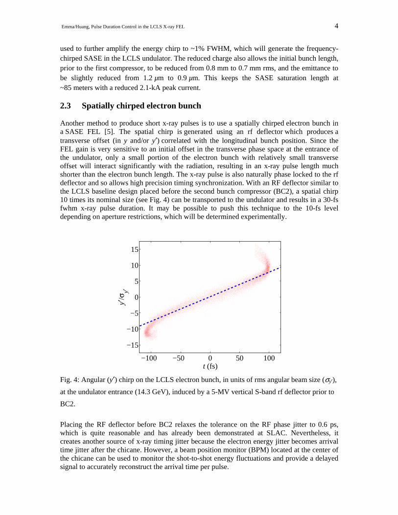
used to further amplify the energy chirp to ~1% FWHM, which will generate the frequency-chirped SASE in the LCLS undulator. The reduced charge also allows the initial bunch length, prior to the first compressor, to be reduced from 0.8 mm to 0.7 mm rms, and the emittance to be slightly reduced from 1.2 µm to 0.9 µm. This keeps the SASE saturation length at ~85 meters with a reduced 2.1-kA peak current. 2.3 Spatially chirped electron bunch Another method to produce short x-ray pulses is to use a spatially chirped electron bunch in a SASE FEL [5]. The spatial chirp is generated using an rf deflector which produces a transverse offset (in y and/or y′) correlated with the longitudinal bunch position. Since the FEL gain is very sensitive to an initial offset in the transverse phase space at the entrance of the undulator, only a small portion of the electron bunch with relatively small transverse offset will interact significantly with the radiation, resulting in an x-ray pulse length much shorter than the electron bunch length. The x-ray pulse is also naturally phase locked to the rf deflector and so allows high precision timing synchronization. With an RF deflector similar to the LCLS baseline design placed before the second bunch compressor (BC2), a spatial chirp 10 times its nominal size (see Fig. 4) can be transported to the undulator and results in a 30-fs fwhm x-ray pulse duration. It may be possible to push this technique to the 10-fs level depending on aperture restrictions, which will be determined experimentally.
−100 −50 0 50 100
−15
−10
−5
0
5
10
15
t (fs)
y′/σ
y′
Fig. 4: Angular (y′) chirp on the LCLS electron bunch, in units of rms angular beam size (σy′),
at the undulator entrance (14.3 GeV), induced by a 5-MV vertical S-band rf deflector prior to
BC2.
Placing the RF deflector before BC2 relaxes the tolerance on the RF phase jitter to 0.6 ps, which is quite reasonable and has already been demonstrated at SLAC. Nevertheless, it creates another source of x-ray timing jitter because the electron energy jitter becomes arrival time jitter after the chicane. However, a beam position monitor (BPM) located at the center of the chicane can be used to monitor the shot-to-shot energy fluctuations and provide a delayed signal to accurately reconstruct the arrival time per pulse.
Emma/Huang, Pulse Duration Control in the LCLS X-ray FEL 5
References
[1] P. Emma et al, Phys. Rev. Lett., 92, 074801 (2004). [2] see, for example, LCLS letter of intent by R. Kienberger, “X-Ray pulse-
measurement by Chirped Pulse Laser Assisted Auger Decay”, June 2004. [3] C. Schroeder et al., Nucl. Instrum. Meth. A483, 89 (2002). [4] S. Krinsky and Z. Huang, Phy. Rev. ST Accel. Beams 6, 050702 (2003). [5] P. Emma and Z. Huang, in FEL2003 Proceedings, to be published in Nucl. Instrum.
Meth. A.