Embed Size (px)
Citation preview

Title: Structural System of North-East Asia Trade Tower in Korea
Authors: Kwang Ryang Chung, President, Dong Yang Structural EngineersDavid Scott, Principal, Ove Arup & PartnersDo Hyun Kim, Senior Researcher, Dong Yang Structural EngineersIn Ho Ha, General Manager, DaewooKi Dong Park, Senior Researcher, Daewoo
Subjects: Building Case StudyStructural Engineering
Keywords: Mega ColumnOutriggersSteelStructure
Publication Date: 2008
Original Publication: CTBUH 2008 8th World Congress, Dubai
Paper Type: 1. Book chapter/Part chapter2. Journal paper3. Conference proceeding4. Unpublished conference paper5. Magazine article6. Unpublished
© Council on Tall Buildings and Urban Habitat / Kwang Ryang Chung; David Scott; Do Hyun Kim; In Ho Ha;Ki Dong Park
ctbuh.org/papers
CTBUH 8th World Congress 2008 �
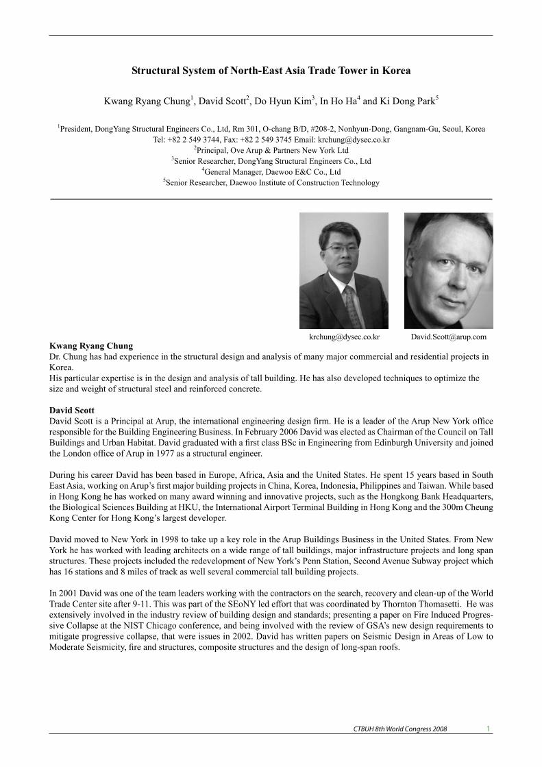
Kwang Ryang ChungDr. Chung has had experience in the structural design and analysis of many major commercial and residential projects in Korea. His particular expertise is in the design and analysis of tall building. He has also developed techniques to optimize the size and weight of structural steel and reinforced concrete.
David ScottDavid Scott is a Principal at Arup, the international engineering design firm. He is a leader of the Arup New York office responsible for the Building Engineering Business. In February 2006 David was elected as Chairman of the Council on Tall Buildings and Urban Habitat. David graduated with a first class BSc in Engineering from Edinburgh University and joined the London office of Arup in 1977 as a structural engineer.
During his career David has been based in Europe, Africa, Asia and the United States. He spent 15 years based in South East Asia, working on Arup’s first major building projects in China, Korea, Indonesia, Philippines and Taiwan. While based in Hong Kong he has worked on many award winning and innovative projects, such as the Hongkong Bank Headquarters, the Biological Sciences Building at HKU, the International Airport Terminal Building in Hong Kong and the 300m Cheung Kong Center for Hong Kong’s largest developer.
David moved to New York in 1998 to take up a key role in the Arup Buildings Business in the United States. From New York he has worked with leading architects on a wide range of tall buildings, major infrastructure projects and long span structures. These projects included the redevelopment of New York’s Penn Station, Second Avenue Subway project which has 16 stations and 8 miles of track as well several commercial tall building projects.
In 2001 David was one of the team leaders working with the contractors on the search, recovery and clean-up of the World Trade Center site after 9-11. This was part of the SEoNY led effort that was coordinated by Thornton Thomasetti. He was extensively involved in the industry review of building design and standards; presenting a paper on Fire Induced Progres-sive Collapse at the NIST Chicago conference, and being involved with the review of GSA’s new design requirements to mitigate progressive collapse, that were issues in 2002. David has written papers on Seismic Design in Areas of Low to Moderate Seismicity, fire and structures, composite structures and the design of long-span roofs.
Structural System of North-East Asia Trade Tower in Korea
Kwang Ryang Chung1, David Scott2, Do Hyun Kim3, In Ho Ha4 and Ki Dong Park5
1President, DongYang Structural Engineers Co., Ltd, Rm 301, O-chang B/D, #208-2, Nonhyun-Dong, Gangnam-Gu, Seoul, Korea Tel: +82 2 549 3744, Fax: +82 2 549 3745 Email: [email protected]
2Principal, Ove Arup & Partners New York Ltd 3Senior Researcher, DongYang Structural Engineers Co., Ltd
4General Manager, Daewoo E&C Co., Ltd 5Senior Researcher, Daewoo Institute of Construction Technology
Abstract This paper introduces the structural system and new outrigger connection of Northeast Asia Trade Tower (NEATT). NEATT comprises 68 stories with a level to the top of the roof +305m and is currently under construction in Song-do, South Korea. NEATT is designated as a landmark of Song-do International Free Trade city. The structural system of NEATT is composed of the perimeter column, corner mega column, core wall, outrigger and belt truss system. This tower can be characterized by its highly irregular shape and two outrigger floors such that the structural members including perimeter columns and belt trusses are out of plumb and several steel members meet at one joint of outrigger truss. The proposed outrigger connection in this paper was conceived to overcome the difficulty of keeping small gaps at the conventional outrigger connections. The new outrigger connection is applied at outrigger truss to acquire structural stability and construction efficiency. The large scale laboratory test showed that the proposed Oil Jack Outrigger Joint System was proved to handle the differential column shortening during the construction. It also efficiently resists the dynamic lateral loads.
Keywords: Tall buildings, Structural System, Adjustment Joint, Outrigger System
Introduction North-East Asia Trade Tower (NEATT), currently
being built in Song-do Free International City, is a 68-story high-rise building. This building has been planned to serve as a landmark that symbolizes Song-do City as an advanced International Free Trade city.
NEATT’s 2nd through the 33rd floors are offered to domestic and foreign companies as 24-hour open business spaces, whereas its 35th through 64th floors are to be used for the highest-grade business hotel. The following is the design summary of NEATT.
Location: Yeonsu-gu, Incheon Total floor space: 138,316 m2 Usage: Offices and a hotel Size: 68 stories above ground level and 3 stories underground Floor Height: 4.3 m (office), 3.7 m (hotel) Structural system: RC Core, Mega columns, Outrigger & Belt truss Foundation: RCD pile foundation Design by Heerim Architects & Planners, KPF Structural design by Dongyang Structural Engineers Co., Ltd. and Ove Arup & Partners New York Ltd. Construction by DAEWOO E&C Co.
Reflecting the latest trends in modern architecture characterized by free and dynamic forms, NEATT has a
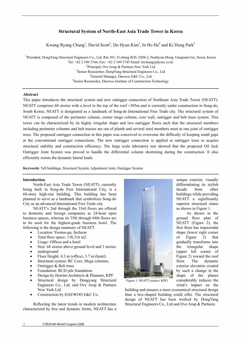
unique exterior, visually differentiating its stylish facade from other buildings while providing NEATT a significantly superior structural status as shown in Figure 1.
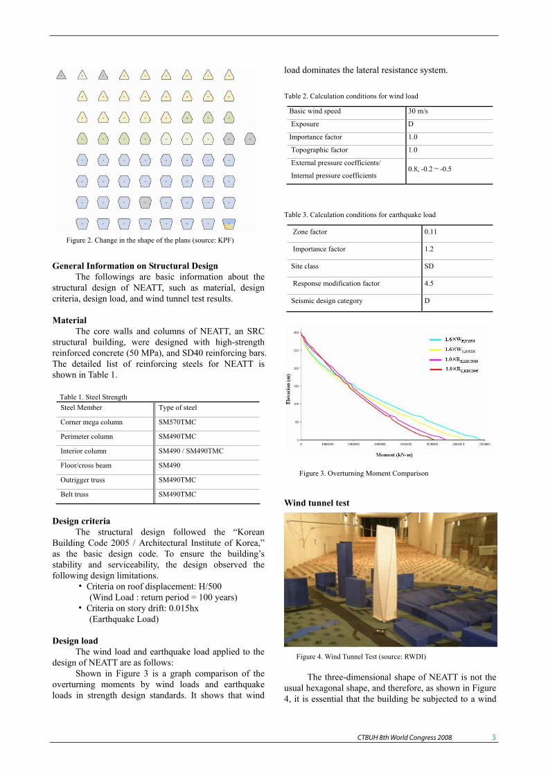
As shown in the ground floor plan of NEATT (Figure 2), the first floor has trapezoidal shape (lower right corner of Figure 2) that gradually transforms into the triangular shape (upper left corner of Figure 2) toward the roof floor. The dynamic exterior elevation created by such a change in the shape of the planes considerably reduces the wind’s impact on the
building and ensures a more economical structural design than a box-shaped building could offer. The structural design of NEATT has been worked by DongYang Structural Engineers Co., Ltd and Ove Arup & Partners.
Figure 1. NEATT (source: KPF)
CTBUH 8th World Congress 2008 �
Structural System of North-East Asia Trade Tower in Korea
Kwang Ryang Chung1, David Scott2, Do Hyun Kim3, In Ho Ha4 and Ki Dong Park5
1President, DongYang Structural Engineers Co., Ltd, Rm 301, O-chang B/D, #208-2, Nonhyun-Dong, Gangnam-Gu, Seoul, Korea Tel: +82 2 549 3744, Fax: +82 2 549 3745 Email: [email protected]
2Principal, Ove Arup & Partners New York Ltd 3Senior Researcher, DongYang Structural Engineers Co., Ltd
4General Manager, Daewoo E&C Co., Ltd 5Senior Researcher, Daewoo Institute of Construction Technology
Abstract This paper introduces the structural system and new outrigger connection of Northeast Asia Trade Tower (NEATT). NEATT comprises 68 stories with a level to the top of the roof +305m and is currently under construction in Song-do, South Korea. NEATT is designated as a landmark of Song-do International Free Trade city. The structural system of NEATT is composed of the perimeter column, corner mega column, core wall, outrigger and belt truss system. This tower can be characterized by its highly irregular shape and two outrigger floors such that the structural members including perimeter columns and belt trusses are out of plumb and several steel members meet at one joint of outrigger truss. The proposed outrigger connection in this paper was conceived to overcome the difficulty of keeping small gaps at the conventional outrigger connections. The new outrigger connection is applied at outrigger truss to acquire structural stability and construction efficiency. The large scale laboratory test showed that the proposed Oil Jack Outrigger Joint System was proved to handle the differential column shortening during the construction. It also efficiently resists the dynamic lateral loads.
Keywords: Tall buildings, Structural System, Adjustment Joint, Outrigger System
Introduction North-East Asia Trade Tower (NEATT), currently
being built in Song-do Free International City, is a 68-story high-rise building. This building has been planned to serve as a landmark that symbolizes Song-do City as an advanced International Free Trade city.
NEATT’s 2nd through the 33rd floors are offered to domestic and foreign companies as 24-hour open business spaces, whereas its 35th through 64th floors are to be used for the highest-grade business hotel. The following is the design summary of NEATT.
Location: Yeonsu-gu, Incheon Total floor space: 138,316 m2 Usage: Offices and a hotel Size: 68 stories above ground level and 3 stories underground Floor Height: 4.3 m (office), 3.7 m (hotel) Structural system: RC Core, Mega columns, Outrigger & Belt truss Foundation: RCD pile foundation Design by Heerim Architects & Planners, KPF Structural design by Dongyang Structural Engineers Co., Ltd. and Ove Arup & Partners New York Ltd. Construction by DAEWOO E&C Co.
Reflecting the latest trends in modern architecture characterized by free and dynamic forms, NEATT has a
unique exterior, visually differentiating its stylish facade from other buildings while providing NEATT a significantly superior structural status as shown in Figure 1.
As shown in the ground floor plan of NEATT (Figure 2), the first floor has trapezoidal shape (lower right corner of Figure 2) that gradually transforms into the triangular shape (upper left corner of Figure 2) toward the roof floor. The dynamic exterior elevation created by such a change in the shape of the planes considerably reduces the wind’s impact on the
building and ensures a more economical structural design than a box-shaped building could offer. The structural design of NEATT has been worked by DongYang Structural Engineers Co., Ltd and Ove Arup & Partners.
Figure 1. NEATT (source: KPF)
CTBUH 8th World Congress 2008 �
General Information on Structural Design The followings are basic information about the
structural design of NEATT, such as material, design criteria, design load, and wind tunnel test results.
Material The core walls and columns of NEATT, an SRC
structural building, were designed with high-strength reinforced concrete (50 MPa), and SD40 reinforcing bars. The detailed list of reinforcing steels for NEATT is shown in Table 1.
Table 1. Steel Strength Steel Member Type of steel
Corner mega column SM570TMC
Perimeter column SM490TMC
Interior column SM490 / SM490TMC
Floor/cross beam SM490
Outrigger truss SM490TMC
Belt truss SM490TMC
Design criteria The structural design followed the “Korean
Building Code 2005 / Architectural Institute of Korea,” as the basic design code. To ensure the building’s stability and serviceability, the design observed the following design limitations.
• Criteria on roof displacement: H/500 (Wind Load : return period = 100 years)
• Criteria on story drift: 0.015hx (Earthquake Load)
Design load The wind load and earthquake load applied to the
design of NEATT are as follows: Shown in Figure 3 is a graph comparison of the
overturning moments by wind loads and earthquake loads in strength design standards. It shows that wind
load dominates the lateral resistance system.
Table 2. Calculation conditions for wind load
Basic wind speed 30 m/s
Exposure D
Importance factor 1.0
Topographic factor 1.0
External pressure coefficients/
Internal pressure coefficients 0.8, -0.2∼-0.5
Table 3. Calculation conditions for earthquake load
Zone factor 0.11
Importance factor 1.2
Site class SD
Response modification factor 4.5
Seismic design category D
Wind tunnel test
The three-dimensional shape of NEATT is not the usual hexagonal shape, and therefore, as shown in Figure 4, it is essential that the building be subjected to a wind
Figure 2. Change in the shape of the plans (source: KPF)
Figure 3. Overturning Moment Comparison
Figure 4. Wind Tunnel Test (source: RWDI)
CTBUH 8th World Congress 2008 �
tunnel test. The wind load and acceleration data acquired from the wind tunnel test were applied to the strength and serviceability design.
The comparison of each floor level moments bythe wind load according to KBC 2005 and the wind load calculated from the wind tunnel test is shown in Figure 5. As was previously discussed, it was confirmed that NEATT’s wind response shows a drastic reduction compared with the code value due to its upward tapered shape.
The acceleration was evaluated through the wind tunnel tests with two different cases: one with the impact of a typhoon and the other without the impact of a typhoon. As shown in Figure 6, both cases satisfied ISO’s acceleration criteria with respect to the return period of one year, five years and ten years.
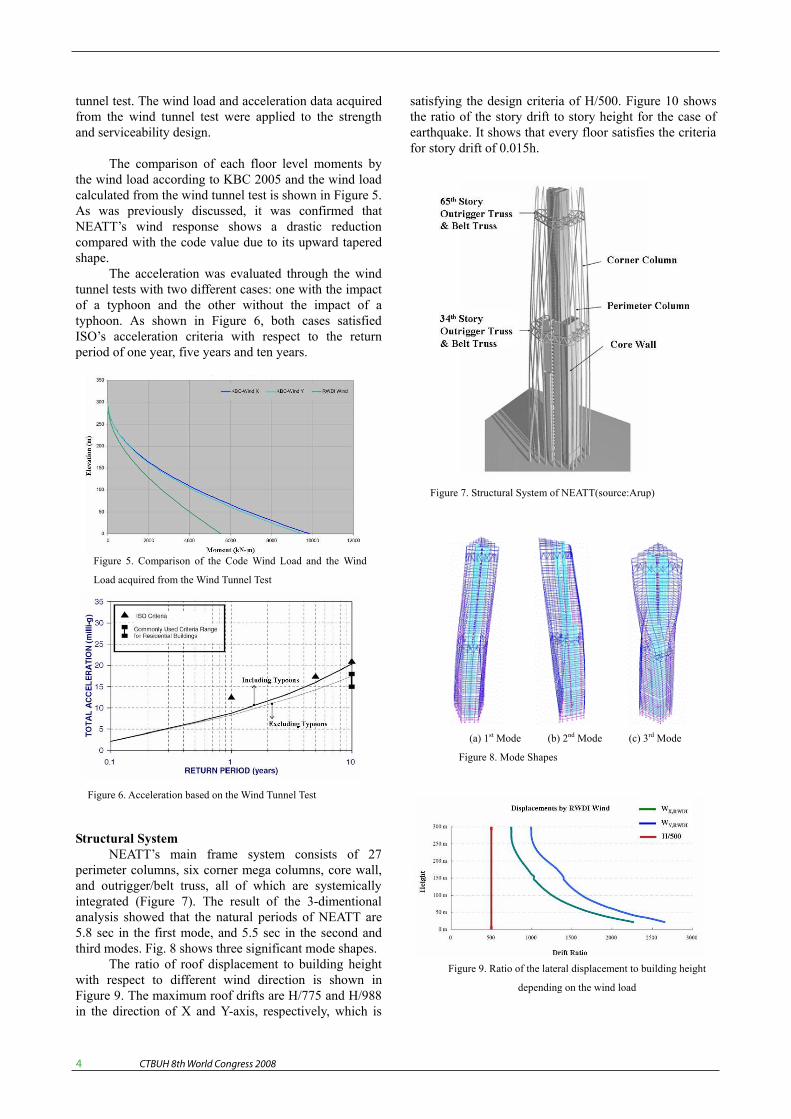
Structural System NEATT’s main frame system consists of 27
perimeter columns, six corner mega columns, core wall, and outrigger/belt truss, all of which are systemicallyintegrated (Figure 7). The result of the 3-dimentional analysis showed that the natural periods of NEATT are 5.8 sec in the first mode, and 5.5 sec in the second and third modes. Fig. 8 shows three significant mode shapes.
The ratio of roof displacement to building height with respect to different wind direction is shown in Figure 9. The maximum roof drifts are H/775 and H/988 in the direction of X and Y-axis, respectively, which is
satisfying the design criteria of H/500. Figure 10 shows the ratio of the story drift to story height for the case of earthquake. It shows that every floor satisfies the criteria for story drift of 0.015h.
Figure 6. Acceleration based on the Wind Tunnel Test
Figure 5. Comparison of the Code Wind Load and the Wind
Load acquired from the Wind Tunnel Test
Figure 7. Structural System of NEATT(source:Arup)
(a) 1st Mode (b) 2nd Mode (c) 3rd Mode
Figure 8. Mode Shapes
Figure 9. Ratio of the lateral displacement to building height
depending on the wind load
CTBUH 8th World Congress 2008 �
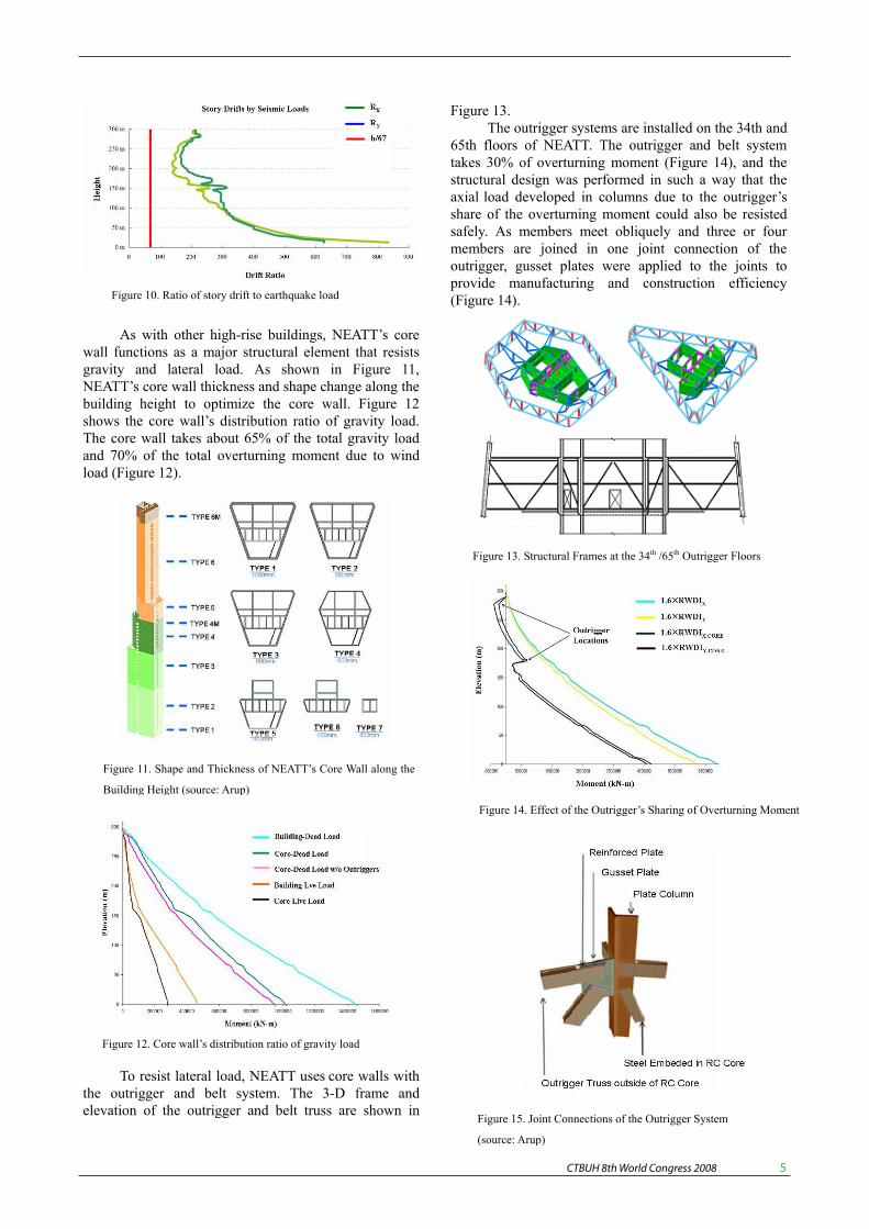
As with other high-rise buildings, NEATT’s core wall functions as a major structural element that resists gravity and lateral load. As shown in Figure 11, NEATT’s core wall thickness and shape change along thebuilding height to optimize the core wall. Figure 12 shows the core wall’s distribution ratio of gravity load. The core wall takes about 65% of the total gravity load and 70% of the total overturning moment due to wind load (Figure 12).
To resist lateral load, NEATT uses core walls with the outrigger and belt system. The 3-D frame and elevation of the outrigger and belt truss are shown in
Figure 13. The outrigger systems are installed on the 34th and
65th floors of NEATT. The outrigger and belt system takes 30% of overturning moment (Figure 14), and the structural design was performed in such a way that the axial load developed in columns due to the outrigger’s share of the overturning moment could also be resisted safely. As members meet obliquely and three or four members are joined in one joint connection of the outrigger, gusset plates were applied to the joints to provide manufacturing and construction efficiency (Figure 14). Figure 10. Ratio of story drift to earthquake load
Figure 11. Shape and Thickness of NEATT’s Core Wall along the
Building Height (source: Arup)
Figure 12. Core wall’s distribution ratio of gravity load
Figure 13. Structural Frames at the 34th /65th Outrigger Floors
Figure 14. Effect of the Outrigger’s Sharing of Overturning Moment
Figure 15. Joint Connections of the Outrigger System
(source: Arup)
CTBUH 8th World Congress 2008 �
A high-rise building sustains a large amount of differential shortening between the core walls and perimeter columns, and consequently, additional stress is induced in the outrigger. A typical solution to this problem is the application of a delayed joint to the outrigger. However, if the delayed joint is applied, the core wall will be the only element that resists lateral loads such as wind and earthquake during construction.
Therefore, the new adjustment joint was applied to NEATT so that both the core walls and the outrigger could resist wind load during construction, successfully securing the building’s structural stability against wind or earthquake load during construction.
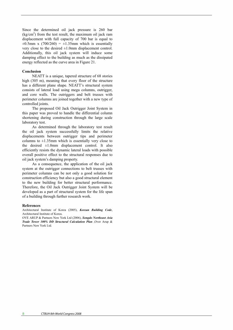
The outrigger is linked to a column, such as in Figure 16(a), at the 65th floor where the outrigger is installed, and is directly linked to the belt truss, shown in Figure 16(b). In case when the outrigger obliquely links to a column, a controlled joint detail is used, as shown in Figure 17, not to pass the axial force delivered from the upper column to the outrigger, but to deliver it directly to the lower column via lateral plates.
Figure 16. Method to joint the outrigger (source : Arup)
Figure 17. Outrigger truss – column joint detail (source : Arup)
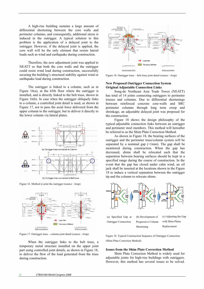
When the outrigger links to the belt truss, a temporary metal structure installed on the upper joint part using controlled joint details, as shown in Figure 18, to deliver the flow of the load generated from the truss during construction.
Figure 18. Outrigger truss – belt truss joint detail (source : Arup)
New Proposed Outrigger Connection System Original Adjustable Connection Links
Song-do Northeast Asia Trade Tower (NEATT) has total of 14 joints connecting outriggers to perimeter trusses and columns. Due to differential shortenings between reinforced concrete core-walls and SRC perimeter columns through long term creep and shrinkage, an adjustable delayed joint was proposed for the construction.
Figure 18 shows the design philosophy of the typical adjustable connection links between an outrigger and perimeter steel members. This method will hereafter be referred to as the Shim Plate Correction Method.
As shown in Figure 18, the bearing surfaces of the outrigger and the perimeter truss/column system will be separated by a nominal gap (<1mm). The gap shall be monitored during construction. When the gap has decreased, shims shall be relocated such that the separation between bearing surfaces should be kept in a specified range during the course of construction. In the event that the gap has closed under calm wind, an oil jack shall be inserted at the locations shown in the Figure 18 to induce a vertical separation between the outrigger tip and the column to relocate shims.
Issues from the Shim Plate Correction Method Shim Plate Correction Method is widely used for
adjustable joints for high-rise buildings with outriggers. However, this method has several issues to be solved.
Figure 18. Typical Construction Sequence of Outrigger Connection
(Shim Plate Correction Method)
Column Shortening
Column Shortening
Gap
Core Wall
Core Wall
Column Shortening
Column Shortening
Gap
Core Wall
Core Wall
Column Shortening
Column Shortening
Gap
Core Wall
Core Wall
Column Shortening
Column Shortening
Gap
Core Wall
Core Wall
Gap
Core Wall
Core Wall
Jack ForceJack Force
Core Wall
Core Wall
Remove Shim PlateRemove
Shim Plate
Install Shim Plate
Install Shim Plate
Jack ForceJack Force
Core Wall
Core Wall
Remove Shim PlateRemove
Shim Plate
Install Shim Plate
Install Shim Plate
Core Wall
Core Wall
Gap
Column Column Gap
Core Wall
Core Wall
Gap
Column Column Gap
GapGap
Column Column GapGap
(a) Specified Gap at
Outrigger Connection
(b) Development of
Progressive Column
Shortening
(c) Adjusting the Gap
with Shim Plates
Replacement

CTBUH 8th World Congress 2008 �
These issues are listed as shown below. If controlling the gap fails, additional stresses in the structural members may develop. Keeping the joint gap in a specified range via shim plate replacements is highly difficult task to carry out. Extra man power and devices are required during the construction for continuous measuring and monitoring process and shim plate replacements.
New Proposed Method (Oil Jack Outrigger Joint System)
This new method was conceived by DAEWOO E&C Co. to overcome the difficulty of keeping such a small gaps at the outrigger connections. This method also should successfully transfer dynamic loads generated from winds and earthquakes. The theoretical functioning mechanism of this new method is shown schematically in Figure 19. The schematic view of the proposed Oil Jack Outrigger Joint System at the outrigger tip is also shown in Figure 19. This new method will hereafter be referred to as “the Oil Jack Outrigger Joint System” or simply the oil jack system.)
This bi-directionally interlocking oil jack system is composed of two oil jacks and pipes with an orifice. To set up the system, first, both top and bottom oil jacks which are connected through the pipes with orifice are installed. Next, oil pressure is applied to push out the rams of both oil jacks until they contact and hold the outrigger tip tight. Finally the supply valve is closed to lock the oil up in two oil jack cylinders and interconnected pipes.
For quasi-static vertical displacement, oil flows slowly through the pipes and orifice. Therefore, the quasi-static vertical displacement due to column shortening will not cause any extra pressure to the oil jacks and accordingly additional stresses in structural members. However, in the event of vertical displacement by dynamic lateral loads such as winds or earthquakes, oil movement is resisted by the orifice. Through this mechanism the oil jacks sustain pressures and the pressure is eventually transferred to the perimeter columns as a form of axial (vertical) loads.
Expected Advantage of Oil Jack Outrigger Joint System
With this oil jack system, the differential column shortening during construction will be automatically handled without any extra stresses to the structural members. Furthermore, the building with the oil jack system is expected to show better performance than the same building with Shim Plate Correction Method since the oil jack system shows some damping property as well as very high stiffness from the test result.
Preliminary Oil Jack Performance Test Preliminary large scale laboratory test was
performed in Daewoo Institute of Construction Technology as shown in Figure 20 to verify if the oil jack system successfully resists dynamic loading with limited oil jack ram displacement. Figure 21 shows displacement - load curve of the tested oil jack system with 0.5mm diameter orifice by a cyclic sine loading. As shown in Figure 19, with given ±5mm displacement controlled loading from dynamic actuators, the oil jack system successfully limits the displacement of steel beam at the connection between oil jacks to ±0.5mm.
Hydraulic Jack
Outrigger
Orifice
Valve
Column
Hydraulic Jack
Outrigger
Orifice
Valve
Column
Hydraulic Jack
Outrigger
Orifice
Valve
Column
Hydraulic Jack
Outrigger
Orifice
Valve
Hydraulic Jack
Outrigger
Orifice
Valve
ColumnColumnColumnColumn
Disp.
Hydraulic Jack
Outrigger
Orifice
Valve
Column
Disp.
Hydraulic Jack
Outrigger
Orifice
Valve
Column
Disp.
Hydraulic Jack
Outrigger
Orifice
Valve
Column
Disp.Disp.
Hydraulic Jack
Outrigger
Orifice
Valve
Column
Hydraulic Jack
Outrigger
Orifice
Valve
Column
Hydraulic Jack
Outrigger
Orifice
Valve
Hydraulic Jack
Outrigger
Orifice
Valve
ColumnColumnColumnColumnColumnColumnColumn
(b) Interlocking
Operation
(a) Installing
Bi-directionally
Interlocked Oil Jack
(c) Schematic View
after Installation
Figure 19. Schematic Figures of New Method
(Outrigger Oil Jack System)
Figure 20. Overview Photograph of Oil Jack System Laboratory Test
Load-Disp GRAPH(Act.Disp. ±5mm C.L.1,000kN)
-2,000
-1,600
-1,200
-800
-400
-
400
800
1,200
1,600
2,000
2,400
-1.5 -1.2 -0.9 -0.6 -0.3 0.0 0.3 0.6 0.9 1.2 1.5
Displacement(mm)
Load(kN)
Figure 21. Displacement – Load Curve for the Tested Oil Jack System
with 0.5mm Diameter Orifice
CTBUH 8th World Congress 2008 �
Since the determined oil jack pressure is 260 bar (kg/cm2) from the test result, the maximum oil jack ram displacement with full capacity of 700 bar is equal to ±0.5mm x (700/260) = ±1.35mm which is essentially very close to the desired ±1.0mm displacement control. Additionally, this oil jack system will induce some damping effect to the building as much as the dissipated energy reflected as the curve area in Figure 21.
Conclusion NEATT is a unique, tapered structure of 68 stories
high (305 m), meaning that every floor of the structure has a different plane shape. NEATT’s structural system consists of lateral load using mega columns, outrigger, and core walls. The outriggers and belt trusses with perimeter columns are joined together with a new type of controlled joints.
The proposed Oil Jack Outrigger Joint System in this paper was proved to handle the differential column shortening during construction through the large scale laboratory test.
As determined through the laboratory test result the oil jack system successfully limits the relative displacements between outrigger tips and perimeter columns to ±1.35mm which is essentially very close to the desired ±1.0mm displacement control. It also efficiently resists the dynamic lateral loads with possible overall positive effect to the structural responses due to oil jack system’s damping property.
As a consequence, the application of the oil jack system at the outrigger connections to belt trusses with perimeter columns can be not only a good solution for construction efficiency but also a good structural element to the new building for better structural performance. Therefore, the Oil Jack Outrigger Joint System will be developed as a part of structural system for the life span of a building through further research work.
References Architectural Institute of Korea (2005), Korean Building Code,Architectural Institute of Korea. OVE ARUP & Partners New York Ltd (2006), Songdo Northeast Asia Trade Tower 100% DD Structural Calculation Plan ,Over Arup & Partners New York Ltd.


![Structural Design of Sky Tower[1]](https://img.pdfslide.us/doc/110x75/55cf8538550346484b8bc7b9/structural-design-of-sky-tower1.jpg)