Embed Size (px)
Citation preview
PROCESS BURNERS
INSTALLAT ION, COMMISS IONING AND MAINTENANCE MANUAL
The information conta constitute a legal liabi
Lanemark Internationa
F D M k I V S E CUSTOMER : END USER :
BURNERS :
R
FD-C BURNEined in this manual is advisory and in general terms only and does not lity on Lanemark International Ltd.
l Ltd reserves the right to supply equipment to their latest specification.
R I E S G A S B U R N E R S Y S T E M J

PROCESS BURNERS
INSTALLAT ION, COMMISS IONING AND MAINTENANCE MANUAL
The information contained i constitute a legal liability on
Lanemark International Ltd F D - E M k I V
CUSTOMER :
END USER : BURNERS :
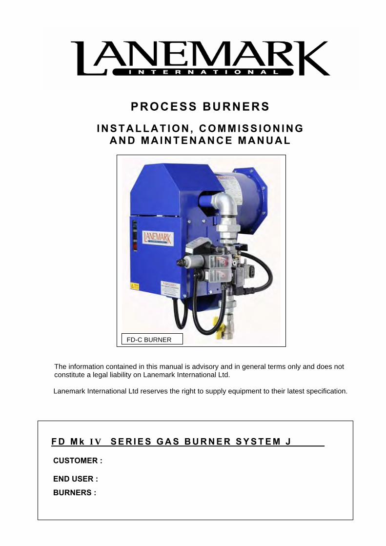
FD-E BURNER
n this manual is advisory and in general terms only and does not Lanemark International Ltd.
reserves the right to supply equipment to their latest specification.
S E R I E S G A S B U R N E R J

PROCESS BURNERS
INSTALLAT ION, COMMISS IONING AND MAINTENANCE MANUAL
The information contained in this manu constitute a legal liability on Lanemark
Lanemark International Ltd reserves th
F D M k I V S E R I E S G A S
CUSTOMER : END USER :
BURNERS :
R
FD-C(GA) BURNEal is advisory and in general terms only and does not International Ltd.
e right to supply equipment to their latest specification.
B U R N E R S Y S T E M J _ _ _ _ _ _
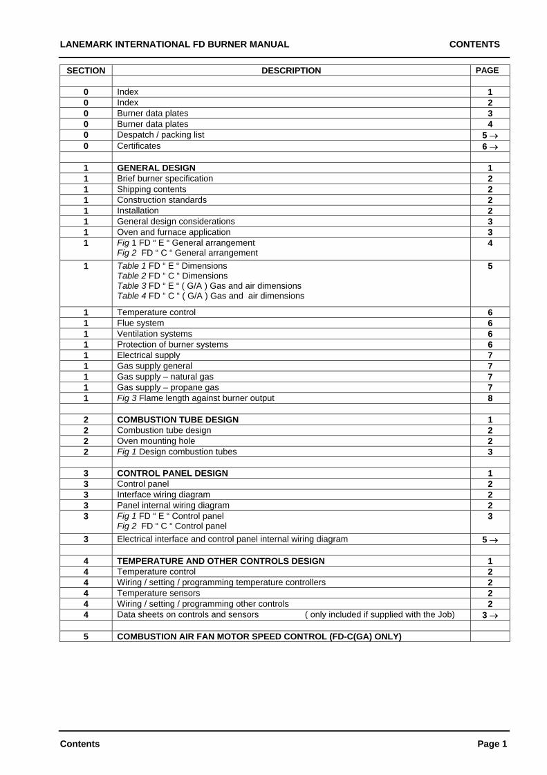
LANEMARK INTERNATIONAL FD BURNER MANUAL CONTENTS
Contents Page 1
SECTION DESCRIPTION PAGE
0 Index 1 0 Index 2 0 Burner data plates 3 0 Burner data plates 4 0 Despatch / packing list 5 0 Certificates 6
1 GENERAL DESIGN 1 1 Brief burner specification 2 1 Shipping contents 2 1 Construction standards 2 1 Installation 2 1 General design considerations 3 1 Oven and furnace application 3 1 Fig 1 FD “ E “ General arrangement
Fig 2 FD “ C “ General arrangement 4
1 Table 1 FD “ E “ Dimensions Table 2 FD “ C “ Dimensions Table 3 FD “ E “ ( G/A ) Gas and air dimensions Table 4 FD “ C “ ( G/A ) Gas and air dimensions
5
1 Temperature control 6 1 Flue system 6 1 Ventilation systems 6 1 Protection of burner systems 6 1 Electrical supply 7 1 Gas supply general 7 1 Gas supply – natural gas 7 1 Gas supply – propane gas 7 1 Fig 3 Flame length against burner output 8
2 COMBUSTION TUBE DESIGN 1 2 Combustion tube design 2 2 Oven mounting hole 2 2 Fig 1 Design combustion tubes 3
3 CONTROL PANEL DESIGN 1 3 Control panel 2 3 Interface wiring diagram 2 3 Panel internal wiring diagram 2 3
Fig 1 FD “ E “ Control panel Fig 2 FD “ C “ Control panel
3
3 Electrical interface and control panel internal wiring diagram 5
4 TEMPERATURE AND OTHER CONTROLS DESIGN 1 4 Temperature control 2 4 Wiring / setting / programming temperature controllers 2 4 Temperature sensors 2 4 Wiring / setting / programming other controls 2 4 Data sheets on controls and sensors ( only included if supplied with the Job) 3
5 COMBUSTION AIR FAN MOTOR SPEED CONTROL (FD-C(GA) ONLY)
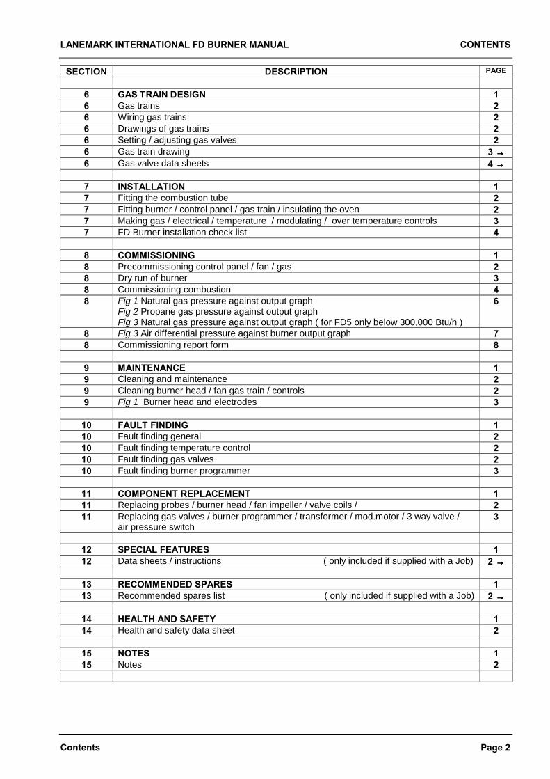
LANEMARK INTERNATIONAL FD BURNER MANUAL CONTENTS
Contents Page 2
SECTION DESCRIPTION PAGE
6 GAS TRAIN DESIGN 16 Gas trains 26 Wiring gas trains 26 Drawings of gas trains 26 Setting / adjusting gas valves 26 Gas train drawing 3 →→→→6 Gas valve data sheets 4 →→→→
7 INSTALLATION 17 Fitting the combustion tube 27 Fitting burner / control panel / gas train / insulating the oven 27 Making gas / electrical / temperature / modulating / over temperature controls 37 FD Burner installation check list 4
8 COMMISSIONING 18 Precommissioning control panel / fan / gas 28 Dry run of burner 38 Commissioning combustion 48 Fig 1 Natural gas pressure against output graph
Fig 2 Propane gas pressure against output graphFig 3 Natural gas pressure against output graph ( for FD5 only below 300,000 Btu/h )
6
8 Fig 3 Air differential pressure against burner output graph 78 Commissioning report form 8
9 MAINTENANCE 19 Cleaning and maintenance 29 Cleaning burner head / fan gas train / controls 29 Fig 1 Burner head and electrodes 3
10 FAULT FINDING 110 Fault finding general 210 Fault finding temperature control 210 Fault finding gas valves 210 Fault finding burner programmer 3
11 COMPONENT REPLACEMENT 111 Replacing probes / burner head / fan impeller / valve coils / 211 Replacing gas valves / burner programmer / transformer / mod.motor / 3 way valve /
air pressure switch3
12 SPECIAL FEATURES 112 Data sheets / instructions ( only included if supplied with a Job) 2 →→→→
13 RECOMMENDED SPARES 113 Recommended spares list ( only included if supplied with a Job) 2 →→→→
14 HEALTH AND SAFETY 114 Health and safety data sheet 2
15 NOTES 115 Notes 2
LANEMARK INTERNATIONAL FD BURNER MANUAL DATA PLATES
Data Plates Page 3
If this manual was sent out with an actual burner ( or several burners built to the same specification ) aduplicate Burner Data Plate will be shown on this page. This will give the actual burner :-
Serial NumbersGas Type ( Natural or Propane )Electrical and Gas Train SpecificationBurner Head Pressure SettingFan Motor Supply Voltage Required
LANEMARK INTERNATIONAL FD BURNER MANUAL DESPATCH/PACKING LIST
Despatch/Packing List Page 5
If this manual was sent out with an actual burner a copy of the Despatch / Packing list will be included after thispage.
This will give all the components and sub-assemblies sent out. Some items may have quantity zero against apart number as these were included for reference only as the customer may be supplying these parts to adesign supplied by Lanemark.
Many part numbers are also accompanied by their corresponding drawing number e.g. gas trains and normallythese drawings will be included in this manual.
LANEMARK INTERNATIONAL FD BURNER MANUAL CERTIFICATES
Certificates Page 6
If this manual was sent out with an actual burner a copy of the :- • Declaration Of Incorporation. • Declaration Of Conformity To Order. • Test Certificates. • Calibration Certificates. • Certificates for equipment supplied by Lanemark International Ltd but not manufactured by Lanemark. will be included after this page if specifically requested by the Customer’s order.
LANEMARK INTERNATIONAL FD BURNER MANUAL SECTION 1 GENERAL DESIGN
Section 1 Page 1
SECTION 1 GENERAL DESIGN
LANEMARK INTERNATIONAL FD MANUAL SECTION 1 GENERAL DESIGN
Section 1 Page 2
BRIEF BURNER SPECIFICATION The FD range of burners are forced draught burners designed for industrial process air heating requirements. Short flame lengths, exceptional flame stability and accurate turndown as low as 9 kW (30,000 Btu/h) are achieved by the unique Lanemark cone design combustion head. Two configurations are available:- FD ‘C’ where the controls are all mounted inside a steel control panel. FD ‘E’ where the controls are all mounted on a mounting plate. For both configurations the combustion air fan, gas train and controls are all prefitted and prewired. The burners can be supplied as on/off, high/low, high/low/ultra low, modulating gas only or modulating air and gas to suit the process requirements. The controls include the gas burner sequence controller, on/off switch, differential air pressure switch, ignition transformer and two off 3-way air valves. These air valves are fitted so that the burner can be used on applications where the recirculation or exhaust fans can run continuously without interfering with the operation of the air pressure switch. The burners can be supplied with 230V or 110V controls and the combustion fans can have 400V 3 phase or 230V single phase motors. The electrical protection rating is IP54 which is suitable for most commercial applications but higher ratings are available to order. The burner’s combustion air fan is generally designed to run continuously when the oven is in use or alternatively it can it can be energised from the burner’s controller to run only when the burner is required to run. The fan motor electrical supply is made via an isolator, contactor and motor overload normally provided by others in the main site motor control panel. Alternatively Lanemark can supply and fit these components. The burner is painted blue and is suitable for mounting directly onto the side of the oven or for down firing as required.
The gas train inlet position must be specified at the time of ordering but can be configured to suit most installations. If the burner is to run for more than 24 hours without being switched off then the burner must be equipped with a control box certified for continuous running to comply with European combustion equipment standards. These burners are generally built to the customers’ specification and may incorporate many variations and features to suit the particular application. If this manual was sent out with an actual burner then a duplicate copy of the burners Data Plates will be shown in the front of this manual giving the principal information and the manual will be specific to that burner project. SHIPPING CONTENTS
The burner is shipped in a single heavy duty cardboard box with an infill of expanded foam. The gas train on larger models may be packed in a transport only position or supplied loose in the box. The control pack on larger models may also be supplied loose in the box. CONSTRUCTION STANDARDS
The burners are generally constructed in accordance with:- EN 476 Part 1: Common Safety Requirements for Industrial Thermoprocessing Equipment. EN 746 Part 2: Safety Requirements for Combustion and Fuel Handling Systems of Industrial Thermoprocessing Equipment. EN 676 Automatic Forced Draught Burners For Gaseous Fuels. As these burners are intended to be incorporated into another machine or system they are supplied with a Certificate of Incorporation as required by the Machinery Directive 89/392/EEC. INSTALLATION
It is UK Law that these burners are installed, commissioned and maintained by competent persons only e.g. C.O.R.G.I and ACOPS registered installers only. For other countries they must be installed and commissioned in accordance with local regulations.
LANEMARK INTERNATIONAL FD MANUAL SECTION 1 GENERAL DESIGN
Section 1 Page 3
GENERAL DESIGN CONSIDERATIONS
The burner must be installed in accordance with the following regulations:- I.E.E Regulations (BS7671) Local Gas Service Area Recommendations BS5440 Part 1 Specification for Installation of Flues BS2915 Specification for Bursting Discs and Bursting Disc Devices BS5440 Part 2 Specification for Installation of Ventilation for Gas Appliances BS6644 Installation of Gas Fired Boilers between 60kW and 2MW British Gas IM/30 Code of Practice for Gas Fired Process Plant British Gas IM/11 Flues for Commercial and Industrial Gas Fired Boilers and Air Heaters British Gas IM/12 Use of Gas in High Temperature Plant British Gas IM/18 Use of Gas in Low Temperature Plant LPGA COP9 LPG Air Plant LPGA COP17 Purging LPG Vessels and Systems IGE/UP/1 Soundness Testing and Purging Of Industrial and Commercial Gas Installations IGE/UP/4 Commissioning Of Gas Fired Plant on Industrial and Commercial Premises IGE/UP/2 Gas Installation Pipe work, Boosters and Compressors on Industrial and Commercial Premises Health and Safety Executive HS (g) 16 Evaporating and Other Ovens DETR Good Practice Guide Selecting and Specifying New Paint Plant and Stoving Ovens For some applications the discharge of flue gas into the atmosphere may be controlled and it is the responsibility of the owner to obtain permission from Local or National Government Departments as required. OVEN AND FURNACE APPLICATION
The burners are suitable for firing into ovens, furnaces and after burners with a pressure of between:- - 5.0 mBar (- 2.0 in.wg) + 0.8 mBar (+ 0.3 in.wg) and process temperatures of up to 500 °C. The standard burner flame tube projects 100 mm from the burner mounting flange.
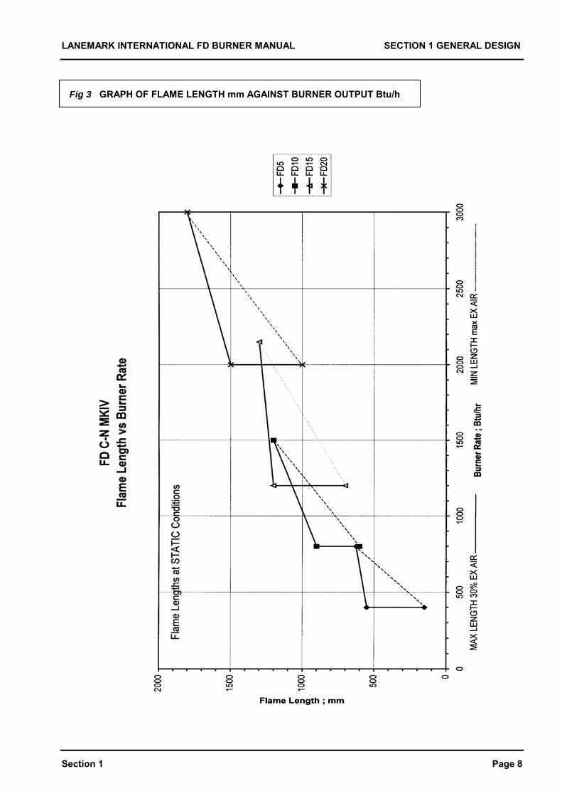
If the burner is mounted on the outside face of an oven and there is typically 150 mm of internal insulation then consideration should be given to the position of the flame as it expands into the combustion chamber through the burner port hole. The neck of the burner port should be protected from flame impingement by fitting a combustion tube or similar. See Fig 1 Section 2. The length of the flame is contained in this manual for various outputs and typical combustion chamber minimum diameters are:- FD5 350 mm. FD10 500 mm. FD15 600 mm. FD20 750 mm. The burner flame is generally quite stable under most firing conditions but if the flame is subject to a cross flow of air (or combustion products) at or in excess of velocities of 6 m/s (20 ft/sec) then a combustion tube should be fitted. This tube shields and stabilises the flame and can recirculate some of the ovens cooler gas back around the base of the combustion tube. A drawing of standard length combustion tubes is contained in this manual and they are available as an optional accessory from Lanemark International Ltd. See Fig 1 Section 2. For higher velocities or temperatures the Technical Department of Lanemark would be pleased to advise on the application and special heads and combustion tubes made from high temperature alloys can generally be designed to protect the combustion head and maintain flame stability. The low fire (also start gas rate) of the burner cannot exceed 30% of the full high setting to comply with standards. The maximum low fire rate is restricted to 74 kW (250,000 Btu/h) on all burners and the minimum is typically 15 kW (50,000 Btu/h) depending on burner type etc. Should a higher low fire rate be required then a pilot stage / low fire / high fire burner should be specified. For down firing applications the burners own combustion air fan should be wired to run continuously and overrun once the oven has been switched off, to prevent hot air from back flowing out of the burner. For very contaminated environments inlet air filters can be supplied and fitted to the combustion fans air inlet or adapter flanges so that clean air can be ducted in from outside. The oven should be fitted with a suitable Bursting Disc or Explosion Relief Panel and if the burner is being fitted to an existing oven the original equipment manufacturer should be consulted to check the suitability of the application.
LANEMARK INTERNATIONAL FD MANUAL SECTION 1 GENERAL DESIGN
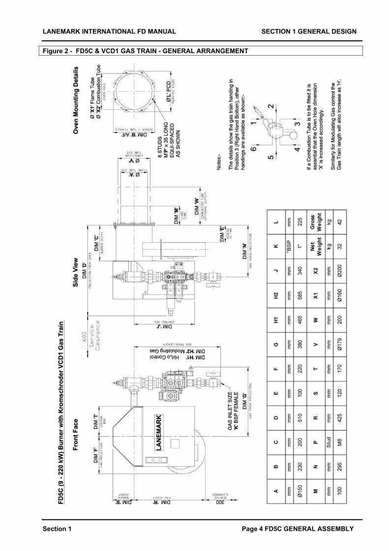
Section 1 Page 4 FD5C GENERAL ASSEMBLY
Figure 2 - FD5C & VCD1 GAS TRAIN - GENERAL ARRANGEMENT
LANEMARK INTERNATIONAL FD MANUAL SECTION 1 GENERAL DESIGN
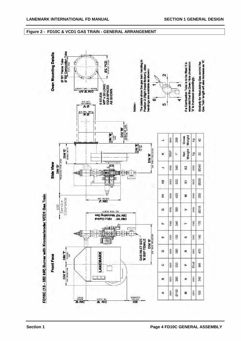
Section 1 Page 4 FD10C GENERAL ASSEMBLY
Figure 2 - FD10C & VCD1 GAS TRAIN - GENERAL ARRANGEMENT

LANEMARK INTERNATIONAL FD MANUAL SECTION 1 GENERAL DESIGN
Section 1 Page 4 FD15C GENERAL ASSEMBLY
Figure 2 - FD15C & VCD2 GAS TRAIN - GENERAL ARRANGEMENT
LANEMARK INTERNATIONAL FD MANUAL SECTION 1 GENERAL DESIGN
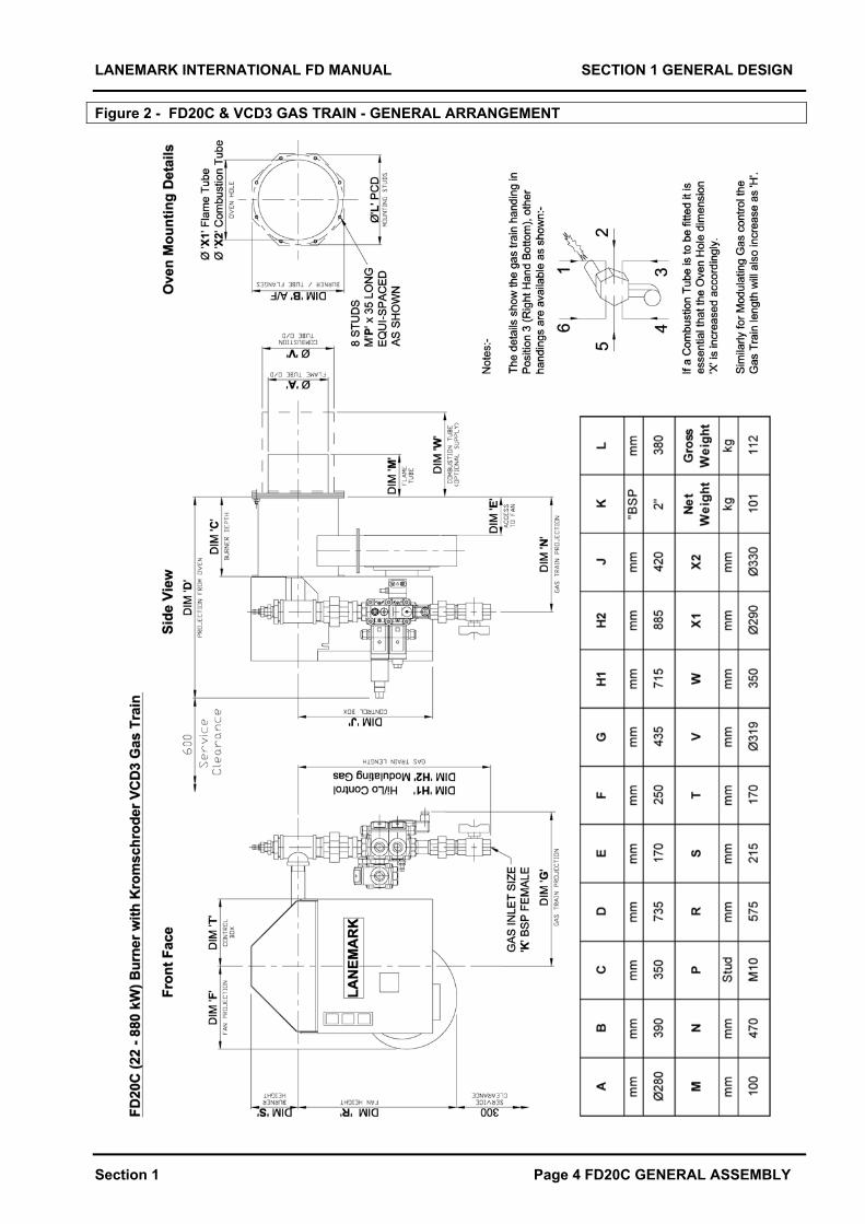
Section 1 Page 4 FD20C GENERAL ASSEMBLY
Figure 2 - FD20C & VCD3 GAS TRAIN - GENERAL ARRANGEMENT
LANEMARK INTERNATIONAL FD MANUAL SECTION 1 GENERAL DESIGN
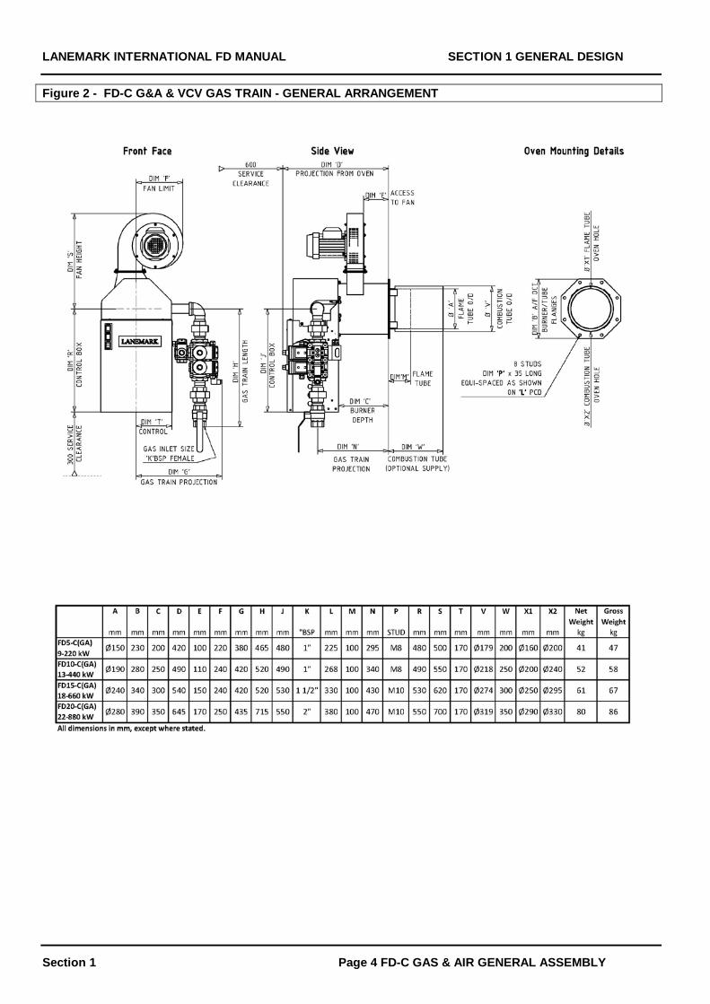
Section 1 Page 4 FD-C GAS & AIR GENERAL ASSEMBLY
Figure 2 - FD-C G&A & VCV GAS TRAIN - GENERAL ARRANGEMENT
LANEMARK INTERNATIONAL FD BURNER MANUAL SECTION 1 GENERAL DESIGN
Section 1 Page 6
TEMPERATURE CONTROL
If Lanemark supplied temperature controls with aburner details of these will be contained in the sectionof this manual Temperature Controls. This sectionalso gives additional detail on specifying, installingand commissioning these controls.
If this manual was sent out with an actual burner thespecific wiring diagram will be contained in the sectionof the manual Control Panels and this will showelectrical interconnections for temperature controls.
The burner can be supplied to operate depending onthe specification ordered as :-
1. On / off at fixed air.2. Or High / low at fixed air.3. Or High / low with 2 stage air.4. Or Modulating gas at fixed air.5. Or Modulating gas and modulating air.
to suit the application requirements.
It is anticipated that the burner will be run continuouslyin low ( start gas ) fire which can be as set as low as15 kW ( 50,000 Btu/h ) depending on model size.
The maximum low ( pilot ) stage is limited to 30% ofthe main flame by European Standards and isrestricted by the pilot gas valve to 74 kW ( 250,000Btu/h ). For higher values of low fire a start gas stage /low fire / high fire burner should be specified.
The burner will usually be commissioned such that lowfire is not sufficient to maintain the oven temperature.Then the main high flame will be brought inintermittently to maintain the set point or the burnerflame will modulate upwards.
It is anticipated that a digital electronic temperaturecontroller will be supplied either by Lanemark as anoptional accessory or by the installer.
This controller should have a set point and anadditional alarm stage with fixed differentials forhigh/low burners. Modulating burners will require asuitable controller that can provide the required controlsignal. These controllers will typically have full 3 termP.I.D control and Autotune to suit the characteristicsof the application.
It is unlikely that simple mechanical thermostats willbe suitable for controlling oven temperature becauseof the speed of response needed.
It is recommended that consideration be given tofitting a second totally independent temperaturecontrol device. This may be necessary if it is criticalthat the process being heated is never allowed to goover temperature. This will act as a High TemperatureTrip Thermostat ( Policeman Thermostat ).
Once its set point has been exceeded the burner isheld off until manual intervention occurs to reset it.
FLUE SYSTEMS
The oven or furnace must be fitted with a suitableexhaust discharging the burner’s products ofcombustion outside the building in a down draughtfree area. If this is not possible the oven/furnacemanufacturer or Lanemark International should beconsulted.
For some installations Local and National GovernmentDepartments should be contacted for approval todischarge flue gas and this is the responsibility of theowner.
VENTILATION SYSTEMS
The burner should only be installed in a productionarea with sufficient natural or mechanical ventilation toensure that there is adequate fresh air for completecombustion and adequate extract to maintain anacceptable working environment.
The burner should not be installed in an area wherethere is a high degree of powered mechanical extractbut only natural ventilation inlet air. With such acombination the mechanical extract system maystarve the burner of combustion air.
For suggested values for natural and mechanicalventilation see BS6644.
Where the air supply quality cannot be ensuredconsideration should be given to ducting fresh air infrom outside.
PROTECTION OF BURNER SYSTEMS
The burner control panel and the gas train aremanufactured to IP54 with regard to their protectionagainst water and dust. This standard is sufficient formost commercial applications.
In food hygiene areas where “ washing down “ takesplace or in areas of excessive condensation theburner’s controls and gas train must be protected fromthe ingress of water or detergent.
If the air is very contaminated with chemicals or dustthen the burner should have its air for combustionvented in from a source of fresh clean air.
Lanemark can supply equipment to higher IPstandards, equipment manufactured from stainlesssteel for food preparation areas and with connectionsfor fresh air ducts.
LANEMARK INTERNATIONAL FD BURNER MANUAL SECTION 1 GENERAL DESIGN
Section 1 Page 7
ELECTRICAL SUPPLY The burner is available with:- 230V 1 Phase 50 Hz or 110V 1 Phase 50 Hz controls and gas trains as given on the Burner Data Plate (a duplicate is shown in the front of this manual). The single phase 230V or 110V control panel supply should be made into the control panel through a M20 cable gland from a suitable isolator and fused supply. The cable should be run in cable of sizes suitable for the panel load of 250 VA. All cable should be suitable for a service temperature of 60 degrees centigrade. THIS BURNER MUST BE EARTHED The burner’s combustion air fan is built into the burner assembly. This will be 400V 3 phase or 230V single phase as specified. The fan motor power and the full load current will be contained on the Data Plate a copy of which is in the front of this manual if this manual was sent out with a burner. The fan should have an independent isolator, motor protection device, contactor with an auxiliary contact provided by others. Alternatively Lanemark would be pleased to supply this as an optional extra. The fan can run continuously from the main plant control panel. The burner must only run when the fan is running and stop immediately if the fan motors overload trips. An auxiliary contact on the motor overload should be interlocked to the burners own control panel. See the wiring diagram details. Alternatively the fans motor contactor can be energised from the burners own control panel as shown in the wiring diagram. All electrical installations should be in accordance with I.E.E Regulations (BS7671). Output signals are available from the burners control panel, at 230V AC or 110V AC as appropriate for burner ON HIGH / ON LOW / AT LOCKOUT. Time switches and ON/OFF switches should be connected as shown in the wiring diagram and temperature controllers as discussed later. Main motor control panels must never backfeed into the Lanemark control panel. Isolating or 110V transformers must be end and not centre tapped. Depending on the model the burner control box may have over/under voltage protection and will not run if the supply voltage is incorrect. Remote reset of control box lockout is possible by briefly applying a 110V or 230V input reset signal or pulling the reset terminal down to neutral as appropriate for the box type. See the wiring diagram.
This reset cable must NOT pick up any induced voltage as it can interfere with the box. If there is a possibility of such voltages screened cable is recommended. GAS SUPPLY GENERAL Before the burner is connected to a new or existing gas supply the Local Gas Supply Service Provider must be consulted to ensure that the gas meter and supply are of adequate size for the load required. The burner gas train includes an isolating ball valve and union to allow the burner to be isolated and removed for servicing and a coarse filter. The pipe work final connections should be made such that it is possible to isolate the gas supply and remove the burner for servicing without removing any gas pipe work. Consideration may be given to making the final connection in an armoured flexible gas hose that complies with current standards. The gas supply pipe work should be designed and installed in accordance with the standards listed previously. GAS SUPPLY NATURAL GAS A stable gas supply pressure supply of:- 20 mBar ( 8 in.wg) minimum inlet pressure 35 mBar (14 in.wg) maximum inlet pressure is required with the burner(s) running and if the supply is a medium pressure supply, or above the maximum required, an additional gas regulator should be installed. Lanemark would be pleased to advise on types, sizes etc. GAS SUPPLY PROPANE GAS The burner should be connected to a Propane gas supply of sufficient capacity so that at the full burner out put, the gas flow rate of the storage system and its regulators is not exceeded. This burner should not be used on Propane/Butane or Propane/Air mixtures. A stable supply pressure of:- 35 mBar (14 in.wg) minimum inlet pressure 50 mBar (20 in.wg) maximum inlet pressure is required with the burner(s) running. If the supply is above the maximum required an additional gas regulator should be installed. Low and high pressure slam shut cut offs with vents must be fitted. Care should be taken in the design and selection to prevent governor lockup or nuisance trip of these. Lanemark would be pleased to advise on types, sizes etc.
LANEMARK INTERNATIONAL FD BURNER MANUAL SECTION 1 GENERAL DESIGN
Section 1 Page 8
Fig 3 GRAPH OF FLAME LENGTH mm AGAINST BURNER OUTPUT Btu/h
LANEMARK INTERNATIONAL FD BURNER MANUAL SECTION 2 COMBUSTION TUBE DESIGN
Section 2 Page 1
SECTION 2 COMBUSTION TUBE DESIGN
LANEMARK INTERNATIONAL FD BURNER MANUAL SECTION 2 COMBUSTION TUBE DESIGN
Section 2 Page 2
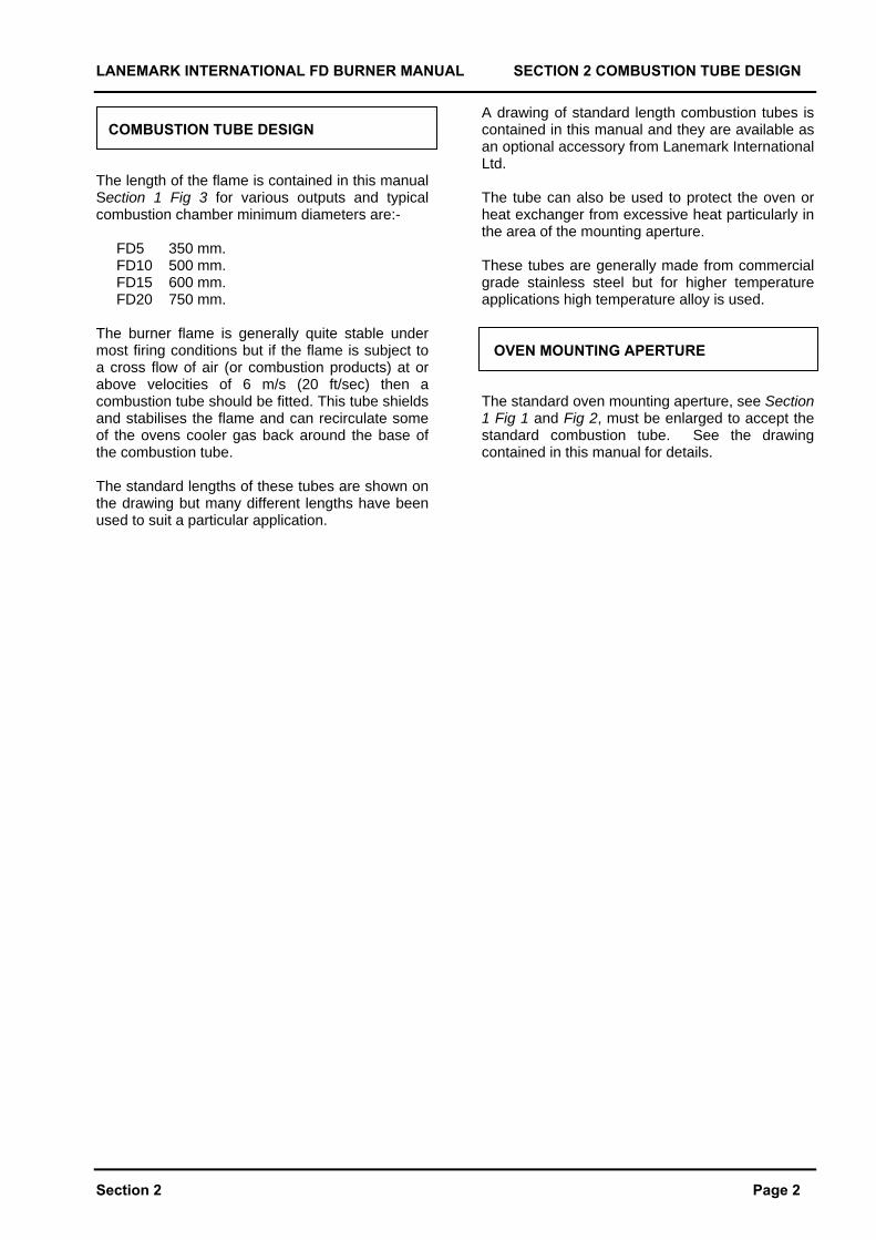
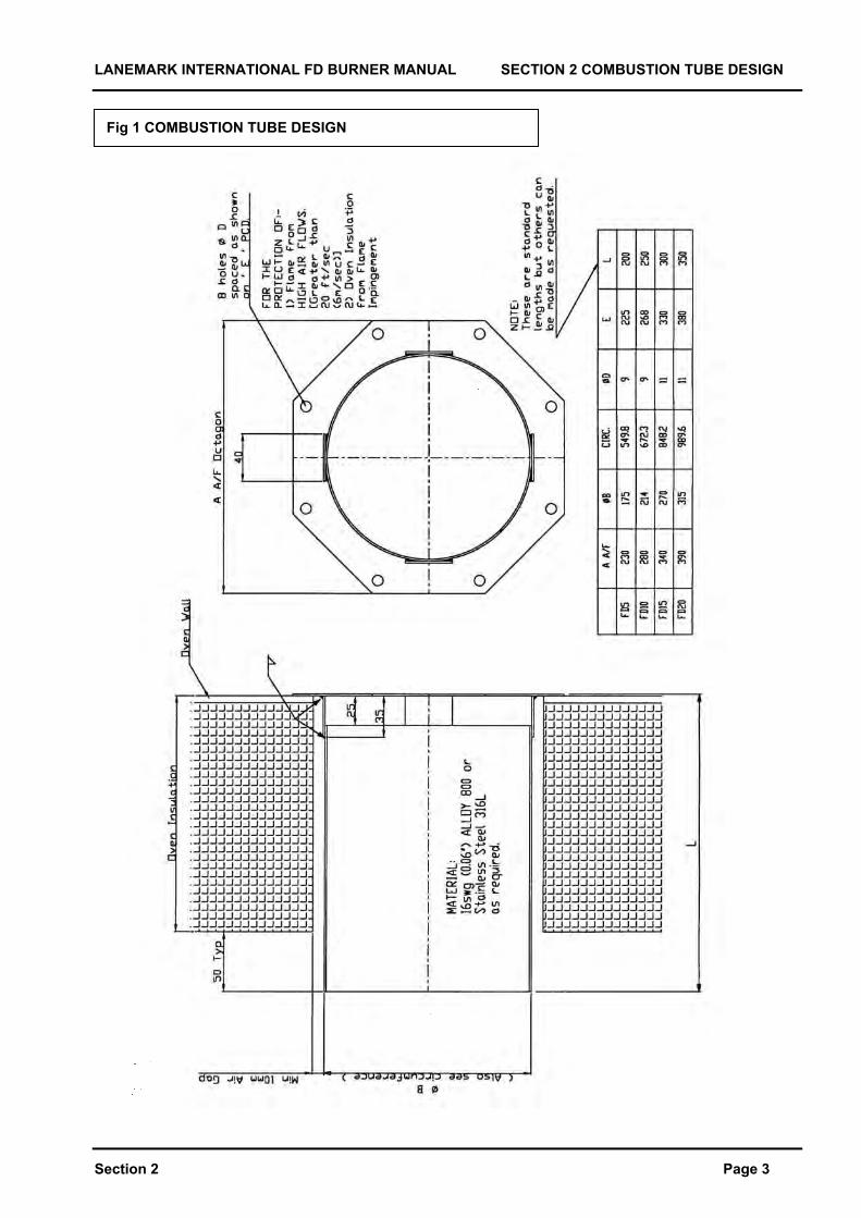
COMBUSTION TUBE DESIGN The length of the flame is contained in this manual Section 1 Fig 3 for various outputs and typical combustion chamber minimum diameters are:- FD5 350 mm. FD10 500 mm. FD15 600 mm. FD20 750 mm. The burner flame is generally quite stable under most firing conditions but if the flame is subject to a cross flow of air (or combustion products) at or above velocities of 6 m/s (20 ft/sec) then a combustion tube should be fitted. This tube shields and stabilises the flame and can recirculate some of the ovens cooler gas back around the base of the combustion tube. The standard lengths of these tubes are shown on the drawing but many different lengths have been used to suit a particular application.
A drawing of standard length combustion tubes is contained in this manual and they are available as an optional accessory from Lanemark International Ltd. The tube can also be used to protect the oven or heat exchanger from excessive heat particularly in the area of the mounting aperture. These tubes are generally made from commercial grade stainless steel but for higher temperature applications high temperature alloy is used. OVEN MOUNTING APERTURE The standard oven mounting aperture, see Section 1 Fig 1 and Fig 2, must be enlarged to accept the standard combustion tube. See the drawing contained in this manual for details.
LANEMARK INTERNATIONAL FD BURNER MANUAL SECTION 2 COMBUSTION TUBE DESIGN
Section 2 Page 3
Fig 1 COMBUSTION TUBE DESIGN
LANEMARK INTERNATIONAL FD BURNER MANUAL SECTION 3 CONTROL PANEL DESIGN
Section 3 Page 1
SECTION 3 CONTROL PANEL DESIGN
LANEMARK INTERNATIONAL FD BURNER MANUAL SECTION 3 CONTROL PANEL DESIGN
Section 3 Page 2
CONTROLS
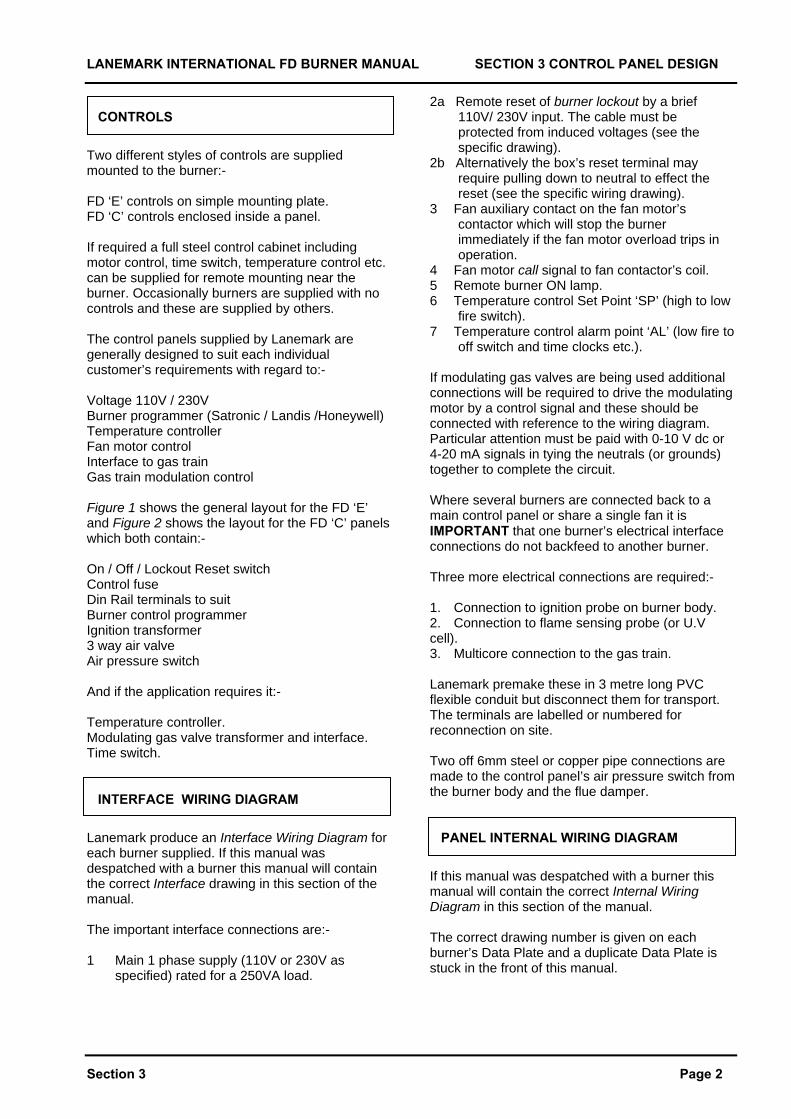
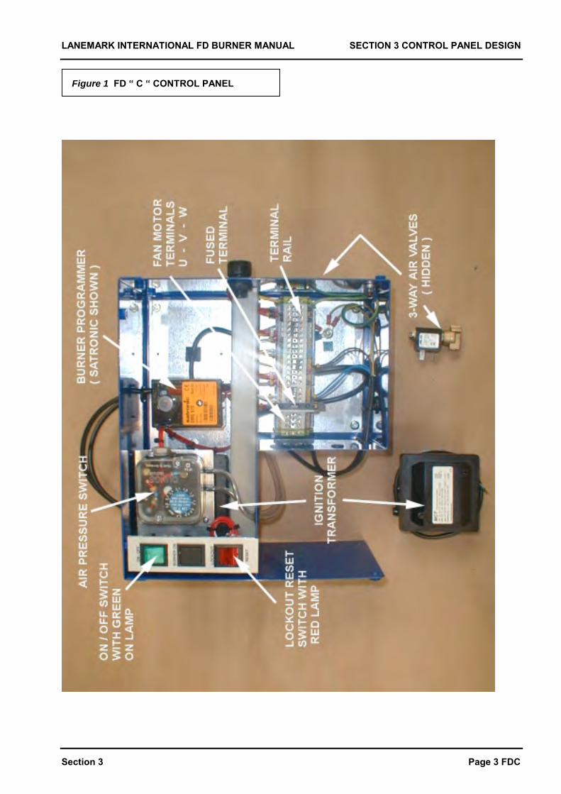
Two different styles of controls are supplied mounted to the burner:- FD ‘E’ controls on simple mounting plate. FD ‘C’ controls enclosed inside a panel. If required a full steel control cabinet including motor control, time switch, temperature control etc. can be supplied for remote mounting near the burner. Occasionally burners are supplied with no controls and these are supplied by others. The control panels supplied by Lanemark are generally designed to suit each individual customer’s requirements with regard to:- Voltage 110V / 230V Burner programmer (Satronic / Landis /Honeywell) Temperature controller Fan motor control Interface to gas train Gas train modulation control Figure 1 shows the general layout for the FD ‘E’ and Figure 2 shows the layout for the FD ‘C’ panels which both contain:- On / Off / Lockout Reset switch Control fuse Din Rail terminals to suit Burner control programmer Ignition transformer 3 way air valve Air pressure switch And if the application requires it:- Temperature controller. Modulating gas valve transformer and interface. Time switch. INTERFACE WIRING DIAGRAM
Lanemark produce an Interface Wiring Diagram for each burner supplied. If this manual was despatched with a burner this manual will contain the correct Interface drawing in this section of the manual. The important interface connections are:- 1 Main 1 phase supply (110V or 230V as
specified) rated for a 250VA load.
2a Remote reset of burner lockout by a brief 110V/ 230V input. The cable must be protected from induced voltages (see the specific drawing).
2b Alternatively the box’s reset terminal may require pulling down to neutral to effect the reset (see the specific wiring drawing).
3 Fan auxiliary contact on the fan motor’s contactor which will stop the burner immediately if the fan motor overload trips in operation.
4 Fan motor call signal to fan contactor’s coil. 5 Remote burner ON lamp. 6 Temperature control Set Point ‘SP’ (high to low
fire switch). 7 Temperature control alarm point ‘AL’ (low fire to
off switch and time clocks etc.). If modulating gas valves are being used additional connections will be required to drive the modulating motor by a control signal and these should be connected with reference to the wiring diagram. Particular attention must be paid with 0-10 V dc or 4-20 mA signals in tying the neutrals (or grounds) together to complete the circuit. Where several burners are connected back to a main control panel or share a single fan it is IMPORTANT that one burner’s electrical interface connections do not backfeed to another burner. Three more electrical connections are required:- 1. Connection to ignition probe on burner body. 2. Connection to flame sensing probe (or U.V cell). 3. Multicore connection to the gas train. Lanemark premake these in 3 metre long PVC flexible conduit but disconnect them for transport. The terminals are labelled or numbered for reconnection on site. Two off 6mm steel or copper pipe connections are made to the control panel’s air pressure switch from the burner body and the flue damper. PANEL INTERNAL WIRING DIAGRAM
If this manual was despatched with a burner this manual will contain the correct Internal Wiring Diagram in this section of the manual. The correct drawing number is given on each burner’s Data Plate and a duplicate Data Plate is stuck in the front of this manual.
LANEMARK INTERNATIONAL FD BURNER MANUAL SECTION 3 CONTROL PANEL DESIGN
Section 3 Page 3 FDC
Figure 1 FD “ C “ CONTROL PANEL
LANEMARK INTERNATIONAL FD MANUAL SECTION 4 TEMPERATURE & OTHER CONTROLS
Section 4 Page 1
SECTION 4
TEMPERATURE AND OTHER CONTROLS DESIGN
LANEMARK INTERNATIONAL FD MANUAL SECTION 4 TEMPERATURE AND OTHER CONTROLS
Section 4 Page 2
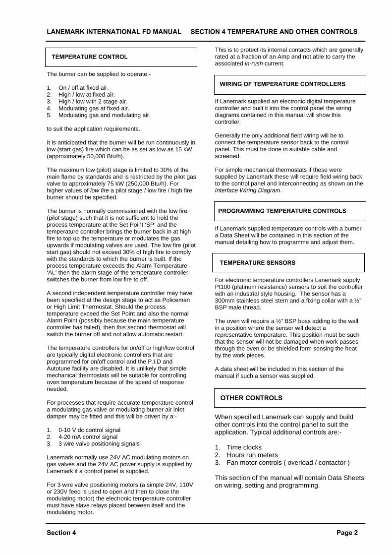
TEMPERATURE CONTROL
The burner can be supplied to operate:- 1. On / off at fixed air. 2. High / low at fixed air. 3. High / low with 2 stage air. 4. Modulating gas at fixed air. 5. Modulating gas and modulating air. to suit the application requirements. It is anticipated that the burner will be run continuously in low (start gas) fire which can be as set as low as 15 kW (approximately 50,000 Btu/h). The maximum low (pilot) stage is limited to 30% of the main flame by standards and is restricted by the pilot gas valve to approximately 75 kW (250,000 Btu/h). For higher values of low fire a pilot stage / low fire / high fire burner should be specified. The burner is normally commissioned with the low fire (pilot stage) such that it is not sufficient to hold the process temperature at the Set Point ‘SP’ and the temperature controller brings the burner back in at high fire to top up the temperature or modulates the gas upwards if modulating valves are used. The low fire (pilot start gas) should not exceed 30% of high fire to comply with the standards to which the burner is built. If the process temperature exceeds the Alarm Temperature ‘AL’ then the alarm stage of the temperature controller switches the burner from low fire to off. A second independent temperature controller may have been specified at the design stage to act as Policeman or High Limit Thermostat. Should the process temperature exceed the Set Point and also the normal Alarm Point (possibly because the main temperature controller has failed), then this second thermostat will switch the burner off and not allow automatic restart. The temperature controllers for on/off or high/low control are typically digital electronic controllers that are programmed for on/off control and the P.I.D and Autotune facility are disabled. It is unlikely that simple mechanical thermostats will be suitable for controlling oven temperature because of the speed of response needed. For processes that require accurate temperature control a modulating gas valve or modulating burner air inlet damper may be fitted and this will be driven by a:- 1. 0-10 V dc control signal 2. 4-20 mA control signal 3. 3 wire valve positioning signals Lanemark normally use 24V AC modulating motors on gas valves and the 24V AC power supply is supplied by Lanemark if a control panel is supplied. For 3 wire valve positioning motors (a simple 24V, 110V or 230V feed is used to open and then to close the modulating motor) the electronic temperature controller must have slave relays placed between itself and the modulating motor.
This is to protect its internal contacts which are generally rated at a fraction of an Amp and not able to carry the associated in-rush current. WIRING OF TEMPERATURE CONTROLLERS
If Lanemark supplied an electronic digital temperature controller and built it into the control panel the wiring diagrams contained in this manual will show this controller. Generally the only additional field wiring will be to connect the temperature sensor back to the control panel. This must be done in suitable cable and screened. For simple mechanical thermostats if these were supplied by Lanemark these will require field wiring back to the control panel and interconnecting as shown on the Interface Wiring Diagram. PROGRAMMING TEMPERATURE CONTROLS
If Lanemark supplied temperature controls with a burner a Data Sheet will be contained in this section of the manual detailing how to programme and adjust them. TEMPERATURE SENSORS
For electronic temperature controllers Lanemark supply Pt100 (platinum resistance) sensors to suit the controller with an industrial style housing. The sensor has a 300mm stainless steel stem and a fixing collar with a ½” BSP male thread. The oven will require a ½” BSP boss adding to the wall in a position where the sensor will detect a representative temperature. This position must be such that the sensor will not be damaged when work passes through the oven or be shielded form sensing the heat by the work pieces. A data sheet will be included in this section of the manual if such a sensor was supplied. OTHER CONTROLS
When specified Lanemark can supply and build other controls into the control panel to suit the application. Typical additional controls are:- 1. Time clocks 2. Hours run meters 3. Fan motor controls ( overload / contactor ) This section of the manual will contain Data Sheets on wiring, setting and programming.
LANEMARK INTERNATIONAL FD BURNER MANUAL SECTION 5 INVERTER DESIGN
Section 5 Page 1
SECTION 5
COMBUSTION AIR FAN SPEED CONTROL
LANEMARK INTERNATIONAL FD BURNER MANUAL SECTION 6 GAS TRAIN DESIGN
Section 6 Page 1
SECTION 6 GAS TRAIN DESIGN
LANEMARK INTERNATIONAL FD BURNER MANUAL SECTION 6 GAS TRAIN DESIGN
Section 6 Page 2
GAS TRAINS Gas trains are designed by Lanemark to meet the specific application and customer requirements e.g. 1. Type and volume of gas 2. Voltage ( 110V or 230V ) 3. Class of IP protection required 4. Destination Country 5. Special features e.g. pressure switches 6. Modulating gas valve motor requirement 7. Fine filters for some countries supplies The gas inlet position must be specified at the design stage e.g. ‘right hand bottom’ to suit the application. Once a gas train is built and delivered to this configuration it must not be modified on site without consulting Lanemark. Gas trains are suitable for a maximum inlet pressure of 100 mbar / 40 in.wg and IP54 unless specifically ordered to a different specification. Lanemark will be pleased to advise on special pressure requirements and supply special pressure regulators to suit. The gas trains on models FD5, FD10, and FD15 are normally supplied prefitted to the burner body and fully prewired. The gas trains on all FD20 and some special gas trains for smaller burners are normally supplied loose for fitting on site as they are too large to be despatched fitted. A union is used and only has to be remade to refit the gas train. The gas train electrical connections will have been fully made for testing at Lanemark but will have been removed for transport. The cable cores are tagged with the terminal numbers and should be reconnected with reference to the wiring diagram contained in this manual if needed. The maximum low (start gas) stage is limited to 30% of the main flame by standards and is restricted by the pilot gas valve to approximately 75 kW (250,000 Btu/h). For higher values of low fire a pilot stage / low fire / high fire burner should be specified. The minimum pilot/low fire rate is typically 15 kW (50,000 Btu/h) depending on the burner model.
WIRING GAS TRAINS The gas train’s gas valves are electrically connected back to the burners control panel. Lanemark generally make this wiring connection and run it in a 3 m flexible PVC conduit. It is disconnected for transport and has to be remade on site. The cable cores are tagged and identified to aid reconnection. The connections are also shown in the wiring diagram contained in this manual if the manual was despatched with a burner. DRAWINGS OF GAS TRAINS If this manual was sent out with a burner a copy of the gas train drawing will be included in this section of the manual. The gas train drawing number is on the burner’s Data Plate and a copy of this Data Plate is stuck in the front of this manual. SETTING / ADJUSTING GAS VALVES The gas train drawing will show the type of gas valves used. Data sheets for the gas valves and other gas components including modulating motors will be contained in this section of the manual. These data sheets will show the basic adjustments that can be made.
LANEMARK INTERNATIONAL BURNER MANUAL SECTION 6 GAS TRAIN DESIGN
Section 6 Kromschroder VCD Gas Valve
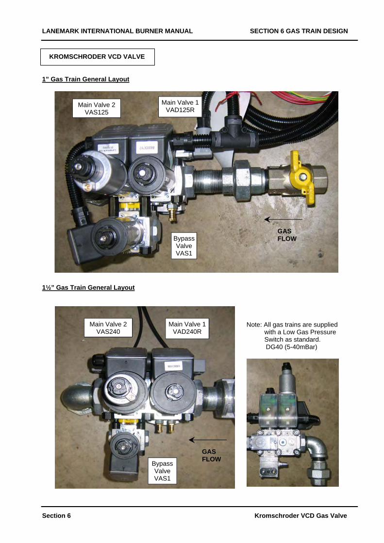
KROMSCHRODER VCD VALVE 1” Gas Train General Layout 1½” Gas Train General Layout
Note: All gas trains are supplied with a Low Gas Pressure Switch as standard.
DG40 (5-40mBar)
GAS FLOW
Bypass Valve VAS1
Main Valve 1VAD240R
Main Valve 2 VAS240
Main Valve 1VAD125R
Main Valve 2 VAS125
GAS FLOW Bypass
Valve VAS1
LANEMARK INTERNATIONAL BURNER MANUAL SECTION 6 GAS TRAIN DESIGN
Section 6 Kromschroder VCD Gas Valve
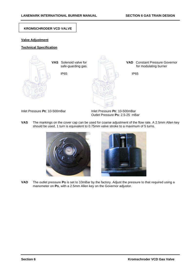
KROMSCHRODER VCD VALVE Valve Adjustment Technical Specification VAS Solenoid valve for VAD Constant Pressure Governor safe-guarding gas. for modulating burner IP65 IP65 Inlet Pressure PE: 10-500mBar Inlet Pressure PE: 10-500mBar Outlet Pressure PG: 2.5-25 mBar VAS The markings on the cover cap can be used for coarse adjustment of the flow rate. A 2.5mm Allen key
should be used, 1 turn is equivalent to 0.75mm valve stroke to a maximum of 5 turns.
VAD The outlet pressure PG is set to 10mBar by the factory. Adjust the pressure to that required using a
manometer on PG, with a 2.5mm Allen key on the Governor adjustor.
LANEMARK INTERNATIONAL BURNER MANUAL SECTION 6 GAS TRAIN DESIGN
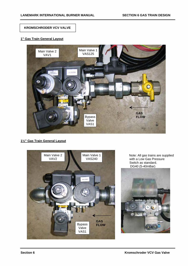
KROMSCHRODER VCV VALVE 1” Gas Train General Layout
Bypass Valve VAS1
GAS FLOW
Main Valve 2 VAV1
Main Valve 1VAS125
1½” Gas Train General Layout Note: All gas trains are supplied
Section 6
with a Low Gas Pressure
Main Valve 1VAS240
Main Valve 2
VAV2
Kromschroder VCV Gas Valve
Switch as standard. DG40 (5-40mBar)
Bypass Valve VAS1
GAS FLOW
LANEMARK INTERNATIONAL BURNER MANUAL SECTION 6 GAS TRAIN DESIGN
Section 6 Kromschroder VCV Gas Valve
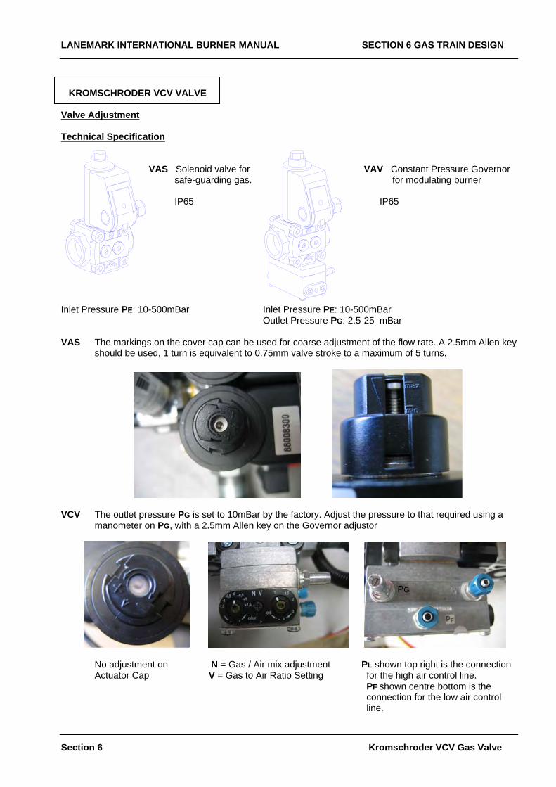
KROMSCHRODER VCV VALVE Valve Adjustment Technical Specification VAS Solenoid valve for VAV Constant Pressure Governor safe-guarding gas. for modulating burner IP65 IP65 Inlet Pressure PE: 10-500mBar Inlet Pressure PE: 10-500mBar Outlet Pressure PG: 2.5-25 mBar VAS The markings on the cover cap can be used for coarse adjustment of the flow rate. A 2.5mm Allen key
should be used, 1 turn is equivalent to 0.75mm valve stroke to a maximum of 5 turns.
VCV The outlet pressure PG is set to 10mBar by the factory. Adjust the pressure to that required using a
manometer on PG, with a 2.5mm Allen key on the Governor adjustor
PG
No adjustment on N = Gas / Air mix adjustment PL shown top right is the connection Actuator Cap V = Gas to Air Ratio Setting for the high air control line. PF shown centre bottom is the connection for the low air control line.
LANEMARK INTERNATIONAL FD BURNER MANUAL SECTION 7 INSTALLATION
Section 7 Page 1
SECTION 7 INSTALLATION
LANEMARK INTERNATIONAL FD BURNER MANUAL SECTION 7 INSTALLATION
Section 7 Page 2
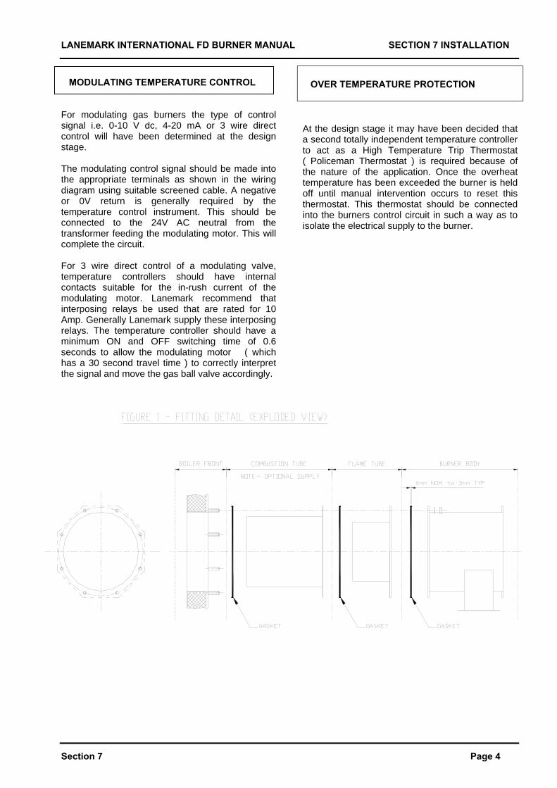
FITTING THE COMBUSTION TUBE For high temperature and high velocity applications a burner combustion tube may have been supplied as a loose item and this should first be fitted as shown in Section 7 Fig 1 to the burner’s firing port. Care should be taken that the annular gap around this combustion tube does not become blocked when mounting the burner. FITTING THE FLAME TUBE The Flame Tube should be fitted to the oven using 8 off studs fitted to the oven as shown in Section 1 Fig 1 and Section 7 Fig 1. The Flame Tube mounting gasket should first be fitted to complete a gas tight seal. FITTING THE BURNER The burner should be fitted to the oven using 8 off studs fitted to the oven as shown in Section 1, Fig 1 and Fig 2. The burner mounting gasket should first be fitted to complete a gas tight seal. FITTING THE CONTROL PANEL The control panel will normally be supplied prefitted to the burner. For special applications the control panel may have been designed and supplied loose for remote mounting close to the burner. In this case the control panel should be fitted within 2 m of the burner body to a cool dry surface so that the flexible conduits reach between the two assemblies.
FITTING THE GAS TRAIN The gas inlet position must be specified at the design stage e.g. “ right hand bottom “ to suit the application. Once a gas train is built and delivered to this configuration it must not be modified on site without consulting Lanemark. The gas trains on FD5, FD10, and FD15 are normally supplied prefitted to the burner body and fully prewired. The gas trains on all FD20 and some special gas trains for smaller burners are normally supplied loose for fitting on site as they are too large to be despatched fitted. A union is used and only has to be remade to refit the gas train. MAKING THE GAS CONNECTION The gas connection should be made to the inlet point on the gas train to the isolating ball valve supplied. The pipework final connection should be made in such a way that it is possible to isolate the gas with the ball valve provided and then to break the union and remove the complete burner without removing any further gas pipework. The weight of the incoming gas pipework will require independent support and must not be supported off the burner. The burner must not be put into operation until the gas supply has been purged and proved sound as given under Design previously. The burners gas train is suitable for an inlet pressure of 100 m.bar maximum. If the gas supply system is to be pressure tested the gas train must be isolated first, as a pressure over 100 mBar will destroy the gas valves. INSULATING THE OVEN The burner contains many plastic parts and fittings. These can be adversely affected by excessive heat being radiated from hot surfaces and also general ambient heat. The burner should be protected from such heat typically by insulating the oven in the area of the burner and providing adequate ventilation. Care should be taken not to obstruct with insulation the burner fan air inlet which faces towards the oven.
LANEMARK INTERNATIONAL FD BURNER MANUAL SECTION 7 INSTALLATION
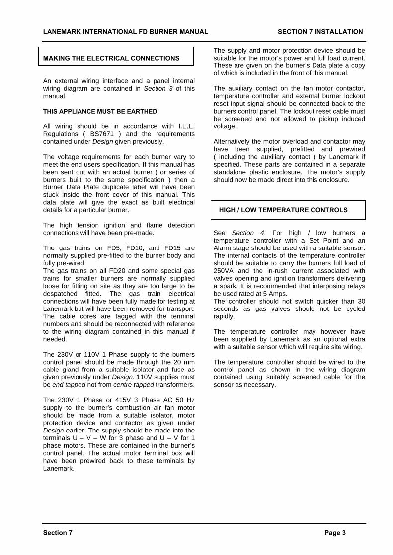
MAKING THE ELECTRICAL CONNECTIONS An external wiring interface and a panel internal wiring diagram are contained in Section 3 of this manual. THIS APPLIANCE MUST BE EARTHED All wiring should be in accordance with I.E.E. Regulations ( BS7671 ) and the requirements contained under Design given previously. The voltage requirements for each burner vary to meet the end users specification. If this manual has been sent out with an actual burner ( or series of burners built to the same specification ) then a Burner Data Plate duplicate label will have been stuck inside the front cover of this manual. This data plate will give the exact as built electrical details for a particular burner.
Section 7 Page 3
The high tension ignition and flame detection connections will have been pre-made. The gas trains on FD5, FD10, and FD15 are normally supplied pre-fitted to the burner body and fully pre-wired. The gas trains on all FD20 and some special gas trains for smaller burners are normally supplied loose for fitting on site as they are too large to be despatched fitted. The gas train electrical connections will have been fully made for testing at Lanemark but will have been removed for transport. The cable cores are tagged with the terminal numbers and should be reconnected with reference to the wiring diagram contained in this manual if needed. The 230V or 110V 1 Phase supply to the burners control panel should be made through the 20 mm cable gland from a suitable isolator and fuse as given previously under Design. 110V supplies must be end tapped not from centre tapped transformers. The 230V 1 Phase or 415V 3 Phase AC 50 Hz supply to the burner’s combustion air fan motor should be made from a suitable isolator, motor protection device and contactor as given under Design earlier. The supply should be made into the terminals U – V – W for 3 phase and U – V for 1 phase motors. These are contained in the burner’s control panel. The actual motor terminal box will have been prewired back to these terminals by Lanemark.
The supply and motor protection device should be suitable for the motor’s power and full load current. These are given on the burner’s Data plate a copy of which is included in the front of this manual. The auxiliary contact on the fan motor contactor, temperature controller and external burner lockout reset input signal should be connected back to the burners control panel. The lockout reset cable must be screened and not allowed to pickup induced voltage. Alternatively the motor overload and contactor may have been supplied, prefitted and prewired ( including the auxiliary contact ) by Lanemark if specified. These parts are contained in a separate standalone plastic enclosure. The motor’s supply should now be made direct into this enclosure. HIGH / LOW TEMPERATURE CONTROLS See Section 4. For high / low burners a temperature controller with a Set Point and an Alarm stage should be used with a suitable sensor. The internal contacts of the temperature controller should be suitable to carry the burners full load of 250VA and the in-rush current associated with valves opening and ignition transformers delivering a spark. It is recommended that interposing relays be used rated at 5 Amps. The controller should not switch quicker than 30 seconds as gas valves should not be cycled rapidly. The temperature controller may however have been supplied by Lanemark as an optional extra with a suitable sensor which will require site wiring. The temperature controller should be wired to the control panel as shown in the wiring diagram contained using suitably screened cable for the sensor as necessary.
LANEMARK INTERNATIONAL FD BURNER MANUAL SECTION 7 INSTALLATION
Section 7 Page 4
MODULATING TEMPERATURE CONTROL For modulating gas burners the type of control signal i.e. 0-10 V dc, 4-20 mA or 3 wire direct control will have been determined at the design stage. The modulating control signal should be made into the appropriate terminals as shown in the wiring diagram using suitable screened cable. A negative or 0V return is generally required by the temperature control instrument. This should be connected to the 24V AC neutral from the transformer feeding the modulating motor. This will complete the circuit. For 3 wire direct control of a modulating valve, temperature controllers should have internal contacts suitable for the in-rush current of the modulating motor. Lanemark recommend that interposing relays be used that are rated for 10 Amp. Generally Lanemark supply these interposing relays. The temperature controller should have a minimum ON and OFF switching time of 0.6 seconds to allow the modulating motor ( which has a 30 second travel time ) to correctly interpret the signal and move the gas ball valve accordingly.
OVER TEMPERATURE PROTECTION At the design stage it may have been decided that a second totally independent temperature controller to act as a High Temperature Trip Thermostat ( Policeman Thermostat ) is required because of the nature of the application. Once the overheat temperature has been exceeded the burner is held off until manual intervention occurs to reset this thermostat. This thermostat should be connected into the burners control circuit in such a way as to isolate the electrical supply to the burner.
LANEMARK INTERNATIONAL FD BURNER MANUAL SECTION 7 INSTALLATION - CHECKLIST
Section 7 Page 5
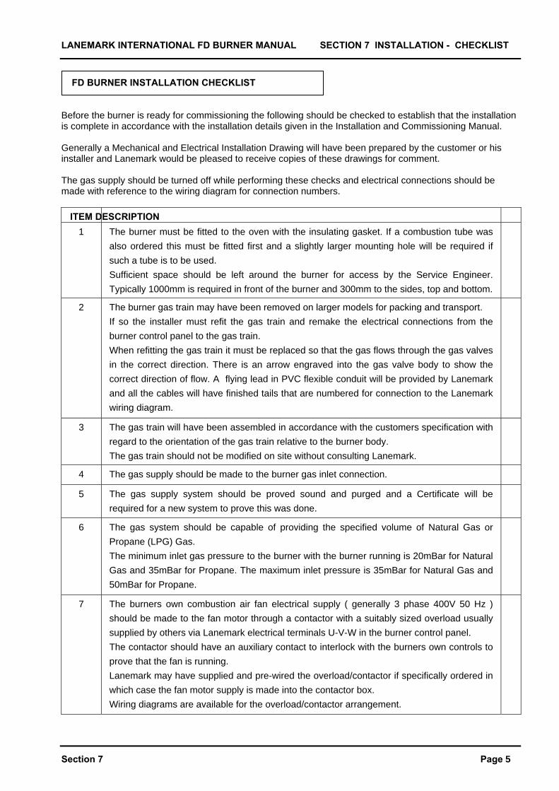
FD BURNER INSTALLATION CHECKLIST Before the burner is ready for commissioning the following should be checked to establish that the installation is complete in accordance with the installation details given in the Installation and Commissioning Manual. Generally a Mechanical and Electrical Installation Drawing will have been prepared by the customer or his installer and Lanemark would be pleased to receive copies of these drawings for comment. The gas supply should be turned off while performing these checks and electrical connections should be made with reference to the wiring diagram for connection numbers.
ITEM DESCRIPTION 1 The burner must be fitted to the oven with the insulating gasket. If a combustion tube was
also ordered this must be fitted first and a slightly larger mounting hole will be required if such a tube is to be used. Sufficient space should be left around the burner for access by the Service Engineer. Typically 1000mm is required in front of the burner and 300mm to the sides, top and bottom.
2 The burner gas train may have been removed on larger models for packing and transport. If so the installer must refit the gas train and remake the electrical connections from the burner control panel to the gas train. When refitting the gas train it must be replaced so that the gas flows through the gas valves in the correct direction. There is an arrow engraved into the gas valve body to show the correct direction of flow. A flying lead in PVC flexible conduit will be provided by Lanemark and all the cables will have finished tails that are numbered for connection to the Lanemark wiring diagram.
3 The gas train will have been assembled in accordance with the customers specification with regard to the orientation of the gas train relative to the burner body. The gas train should not be modified on site without consulting Lanemark.
4 The gas supply should be made to the burner gas inlet connection.
5 The gas supply system should be proved sound and purged and a Certificate will be required for a new system to prove this was done.
6 The gas system should be capable of providing the specified volume of Natural Gas or Propane (LPG) Gas. The minimum inlet gas pressure to the burner with the burner running is 20mBar for Natural Gas and 35mBar for Propane. The maximum inlet pressure is 35mBar for Natural Gas and 50mBar for Propane.
7 The burners own combustion air fan electrical supply ( generally 3 phase 400V 50 Hz ) should be made to the fan motor through a contactor with a suitably sized overload usually supplied by others via Lanemark electrical terminals U-V-W in the burner control panel. The contactor should have an auxiliary contact to interlock with the burners own controls to prove that the fan is running. Lanemark may have supplied and pre-wired the overload/contactor if specifically ordered in which case the fan motor supply is made into the contactor box. Wiring diagrams are available for the overload/contactor arrangement.
LANEMARK INTERNATIONAL FD BURNER MANUAL SECTION 7 INSTALLATION – CHECKLIST
Section 7 Page 6
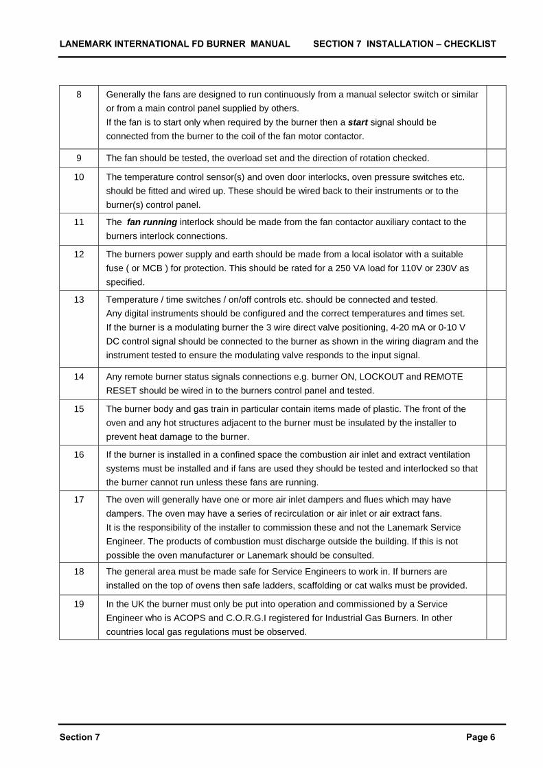
8 Generally the fans are designed to run continuously from a manual selector switch or similar or from a main control panel supplied by others. If the fan is to start only when required by the burner then a start signal should be connected from the burner to the coil of the fan motor contactor.
9 The fan should be tested, the overload set and the direction of rotation checked.
10 The temperature control sensor(s) and oven door interlocks, oven pressure switches etc. should be fitted and wired up. These should be wired back to their instruments or to the burner(s) control panel.
11 The fan running interlock should be made from the fan contactor auxiliary contact to the burners interlock connections.
12 The burners power supply and earth should be made from a local isolator with a suitable fuse ( or MCB ) for protection. This should be rated for a 250 VA load for 110V or 230V as specified.
13 Temperature / time switches / on/off controls etc. should be connected and tested. Any digital instruments should be configured and the correct temperatures and times set. If the burner is a modulating burner the 3 wire direct valve positioning, 4-20 mA or 0-10 V DC control signal should be connected to the burner as shown in the wiring diagram and the instrument tested to ensure the modulating valve responds to the input signal.
14 Any remote burner status signals connections e.g. burner ON, LOCKOUT and REMOTE RESET should be wired in to the burners control panel and tested.
15 The burner body and gas train in particular contain items made of plastic. The front of the oven and any hot structures adjacent to the burner must be insulated by the installer to prevent heat damage to the burner.
16 If the burner is installed in a confined space the combustion air inlet and extract ventilation systems must be installed and if fans are used they should be tested and interlocked so that the burner cannot run unless these fans are running.
17 The oven will generally have one or more air inlet dampers and flues which may have dampers. The oven may have a series of recirculation or air inlet or air extract fans. It is the responsibility of the installer to commission these and not the Lanemark Service Engineer. The products of combustion must discharge outside the building. If this is not possible the oven manufacturer or Lanemark should be consulted.
18 The general area must be made safe for Service Engineers to work in. If burners are installed on the top of ovens then safe ladders, scaffolding or cat walks must be provided.
19 In the UK the burner must only be put into operation and commissioned by a Service Engineer who is ACOPS and C.O.R.G.I registered for Industrial Gas Burners. In other countries local gas regulations must be observed.
LANEMARK INTERNATIONAL FD BURNER MANUAL SECTION 8 COMMISSIONING
Section 8 Page 1
SECTION 8 COMMISSIONING
LANEMARK INTERNATIONAL FD BURNER MANUAL SECTION 8 COMMISSIONING
PRECOMMISSONING THE BURNERS ELECTRICAL CONTROL PANEL THIS APPLIANCE MUST BE EARTHED These tests can only be carried out by suitably qualified electricians. Carry out the following electrical safety checks using a multimeter. Do not use a P.A.T (portable appliance tester) as high voltages generated could damage the electronics in temperature controllers and the Satronic Control Box and give a false reading. Earth Continuity Check 1. The appliance must be disconnected from the main supply. 2. Set the multimeter to Ohms x 1 scale and zero if necessary. 3. Measure the resistance between the earth connection point in the burner’s junction box and the earth connection point from the supply panel or distribution board. 4. If the resistance is greater than 0.1 Ohm then check that the earth cable size is adequate and that all connections are clean, sound and correctly made. Short Circuit Check 1. The burner must be electrically disconnected from the main supply and the burners own ON/OFF switch must be ON and any temperature controllers or time clocks interlinked should be calling. 2. Set the meter to the Ohms scale x 1 and measure the resistance between the incoming live and neutral terminals in the burner’s junction box. If the meter reads zero then there is a direct short circuit and a fault that should be rectified. 3. Set the meter to Ohms x 100 scale and measure the resistance between the burner’s earth connection point and the its incoming live terminal. If the resistance seen is less than infinity then there is a fault that requires rectifying.
Polarity Check Connect the burner control panel to the incoming supply set the meter to read AC Volts by 300V scale. If an isolating or step down transformer has been used the secondary side must be end tapped and not centre tapped as this can interfere with the operation of the Satronic programmer. 1. Measure the voltage between the incoming live and neutral terminals in the burner’s junction box and it should read typically 230V AC or 110V as appropriate. The Satronic control box has under/over voltage protection and will not run if the supply is incorrect. 2. Measure the voltage between the incoming neutral and the earth connection in the burner’s electrical junction box. The voltage should read less than 15V AC. 3. If these voltages are not seen than a neutral fault or polarity fault may exist. If very sensitive earth leakage trips have been fitted to the electrical installation then some types of multi meter may cause them to trip while attempting to measure voltages to earth. Resistance to Earth Check 1. The burner must be electrically disconnected from the main supply and the burners own ON/OFF switch must be ON and any temperature controllers or time clocks interlinked should be calling. 2. Set the meter to Ohms x 100 scale. 3. Measure the resistance between the incoming live connection and the earth connection in the burner’s electrical junction box. The reading should be infinity and if there is any other reading then there is a fault which should be isolated and rectified. PRECOMMISSIONING THE BURNERS ELECTRICAL 1 OR 3 PHASE FAN 1. Generally the connections will be checked in a similar way as given previously. Look for 230V to neutral on 1 phase and 400V between phases on 3 phase motors. 2. For 3 phase motors use the manual button on the motor contactor or similar and check the motor is rotating in the correct direction. If not isolate and reverse two of the phase connections. 3. For 1 and 3 phase motors set the overload or motor protection device in accordance with maker’s instructions and with reference to the fan motor kW rating and full load current.
Section 8 Page 2
LANEMARK INTERNATIONAL FD BURNER MANUAL SECTION 8 COMMISSIONING
PRECOMMISSIONING GAS The gas pipework system from the gas meter to the burner should be sound and purged in accordance with the standards given previously. A Test and Purging Certificate will be available to show this was completed. With the gas isolated at the main inlet, the main gas train outlet (and pilot line outlet isolating valve if fitted) the following checks should be undertaken to prove that the gas train valves are sound and have not been damaged in transit :- 1. With reference to the gas train schematic drawing fit a manometer to the inlet pressure test nipple. 2. Open the main isolating gas cock briefly and then close it. The gas trapped between the main isolating gas cock and the first main valve seat should remain at constant pressure for 2 minutes. If loss of pressure is seen then the main valves or the pilot bypass gas valve seats are letting by and it is faulty and must be replaced as given later under Maintenance. Replace all test nipples. DRY RUN OF BURNER WITH DMG BOX
Section 8 Satronic DMG Box Page 3
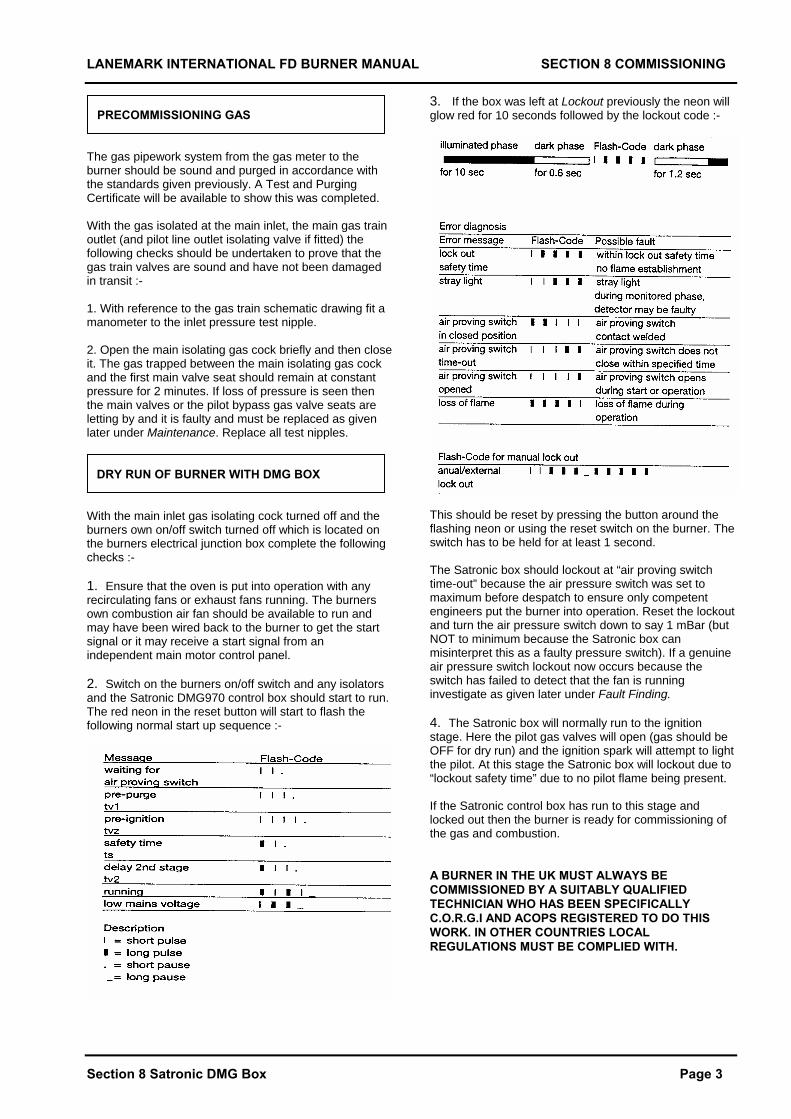
With the main inlet gas isolating cock turned off and the burners own on/off switch turned off which is located on the burners electrical junction box complete the following checks :- 1. Ensure that the oven is put into operation with any recirculating fans or exhaust fans running. The burners own combustion air fan should be available to run and may have been wired back to the burner to get the start signal or it may receive a start signal from an independent main motor control panel. 2. Switch on the burners on/off switch and any isolators and the Satronic DMG970 control box should start to run. The red neon in the reset button will start to flash the following normal start up sequence :-
3. If the box was left at Lockout previously the neon will glow red for 10 seconds followed by the lockout code :-
This should be reset by pressing the button around the flashing neon or using the reset switch on the burner. The switch has to be held for at least 1 second. The Satronic box should lockout at “air proving switch time-out” because the air pressure switch was set to maximum before despatch to ensure only competent engineers put the burner into operation. Reset the lockout and turn the air pressure switch down to say 1 mBar (but NOT to minimum because the Satronic box can misinterpret this as a faulty pressure switch). If a genuine air pressure switch lockout now occurs because the switch has failed to detect that the fan is running investigate as given later under Fault Finding. 4. The Satronic box will normally run to the ignition stage. Here the pilot gas valves will open (gas should be OFF for dry run) and the ignition spark will attempt to light the pilot. At this stage the Satronic box will lockout due to “lockout safety time” due to no pilot flame being present. If the Satronic control box has run to this stage and locked out then the burner is ready for commissioning of the gas and combustion. A BURNER IN THE UK MUST ALWAYS BE COMMISSIONED BY A SUITABLY QUALIFIED TECHNICIAN WHO HAS BEEN SPECIFICALLY C.O.R.G.I AND ACOPS REGISTERED TO DO THIS WORK. IN OTHER COUNTRIES LOCAL REGULATIONS MUST BE COMPLIED WITH.
LANEMARK INTERNATIONAL FD BURNER MANUAL SECTION 8 COMMISSIONING
COMMISSIONING COMBUSTION
Section 8 Satronic DMG Box Page 4
All burners are fired at works as part of the final inspection procedure but final settings can only be set on site to suit a particular application. A BURNER IN THE UK MUST ALWAYS BE COMMISSIONED BY A SUITABLY QUALIFIED TECHNICIAN WHO HAS BEEN SPECIFICALLY C.O.R.G.I AND ACOPS REGISTERED TO DO THIS WORK. IN OTHER COUNTRIES LOCAL REGULATIONS MUST BE COMPLIED WITH. The following settings and checks should be made after the precommissioning procedure has been completed. The main inlet gas isolating cock should be OFF and the burner should be turned off at its own on/off switch. Air Pressure Switch and Air Inlet Damper 1. The air pressure switch was despatched set to maximum. This has then been turned down to typically 1 mBar during the precommissioning stage to allow the burner to run. If not do this now but do not set the pressure switch to minimum because the Satronic box may misinterpret this a faulty pressure switch. 2. The air inlet damper on the burner’s combustion air fan should be set full open. 3. The electrical link in the control panel (6–6A Service Engineers low fire hold link) should be removed so that the burner will run on pilot only. 4. The burners on/off switch and any other external controls should be brought on and the main isolating gas cock should be turned on. 5. The burner will start to run and the Satronic programmer will start to flash as shown previously until the ignition stage is reached. If the gas pipework is not completely purged of air the burner may lock out on the first few attempts at ignition. If lockout does occur the cause should be found by interpreting the lockout signal code or by using the Satronic Satropen to read the lockout code. ( Full instructions for the operation and use of the Satropen are contained later in this manual). 6. Once the pilot flame is established the Satronic box would normally bring on the main gas but as the electrical link 6 - 6a has been removed the second main valve coil will not be energised. 7. The pilot flame can be adjusted to give a reliable flame by adjusting the pilot gas rate adjuster screw. (The location of this adjuster screw is shown previously in this manual). To comply with standards it must not exceed 30% of the main flame rate. The Satropen should be used to read the flame strength signal. It should read 200%. If the signal is less than this increase the gas rate.
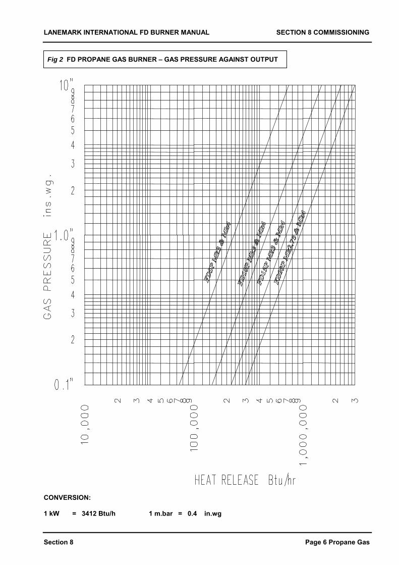
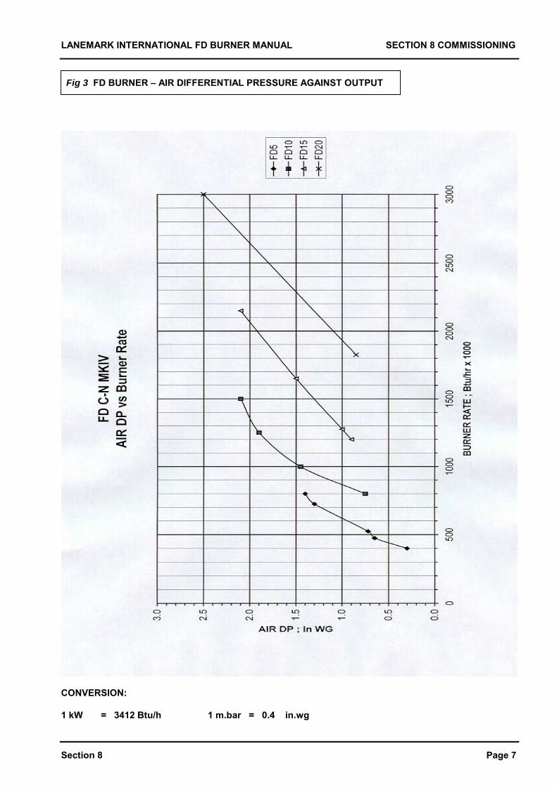
8. Switch the burner off and replace the electrical link 6 – 6A and turn the inlet ball cock 2/3rds off. Fit a manometer to the gas pressure test point on the burner main valve outlet or head. From the burners Data Plate (or the graphs contained in this manual) obtain the gas head pressure required to set the burner on the required rate. 9. Restart the burner and it will run to the main flame stage this time. As the burner runs to main flame watch the gas head pressure rise and progressively open the inlet gas ball cock and set the main gas pressure on the main gas valve governor. (An illustration of the adjuster position is contained previously in this manual and there may be a protective dust cover over the adjuster screw proper). To increase gas turn the governor screw clockwise and anticlockwise to decrease. 10. Once the gas pressure has been correctly set for main flame the combustion should be set. On many ovens and processes it is not possible to measure combustion but the following figures are typical for high fire settings if the burner were to be installed on an indirect heat exchanger or similar. Natural Gas Oxygen ( O2 ) 6.0 % Carbon dioxide ( CO2 ) 8.5 % Carbon monoxide ( CO ) 100ppm ( maximum ) Propane Gas Oxygen ( O2 ) 6.5 % Carbon dioxide ( CO2 ) 9.5 % Carbon monoxide ( CO ) 100ppm ( maximum ) The flue gas temperature when the system is up to its operating temperature will depend entirely on the characteristics of the system. The combustion air is set by adjusting the position of the combustion air damper blade. This is normally set to fully open for most applications. If the burner however is not being used to deliver its full potential output there could be too much air if the damper is set fully open. Figure 3 is a graph of differential air pressure against burner output. It can be used as an approximate guide to setting the damper for other settings other than full open. The fan fixing nuts have to be slackened off to move the combustion air damper blade and must always be retightened afterwards. Once set the start gas and main flame gas pressures should be rechecked as the damper can have a slight influence on the gas pressure. 11. The air pressure switch should be set when the flue and combustion system are cold and after the damper has been set. With the combustion air fan and any other fans fitted to the oven running, but with the burner off, measure the differential air pressure at the 2 test point on the burner body labelled high and low air.
LANEMARK INTERNATIONAL FD BURNER MANUAL SECTION 8 COMMISSIONING
Section 8 Satronic DMG Box Page 5
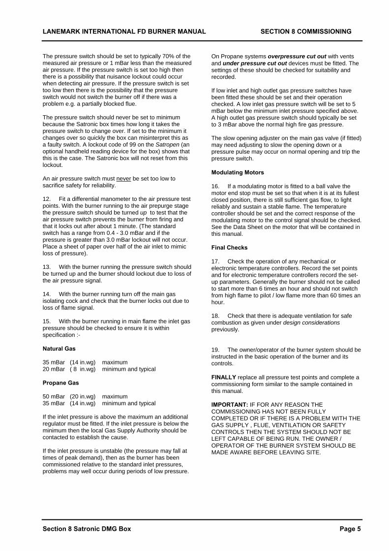
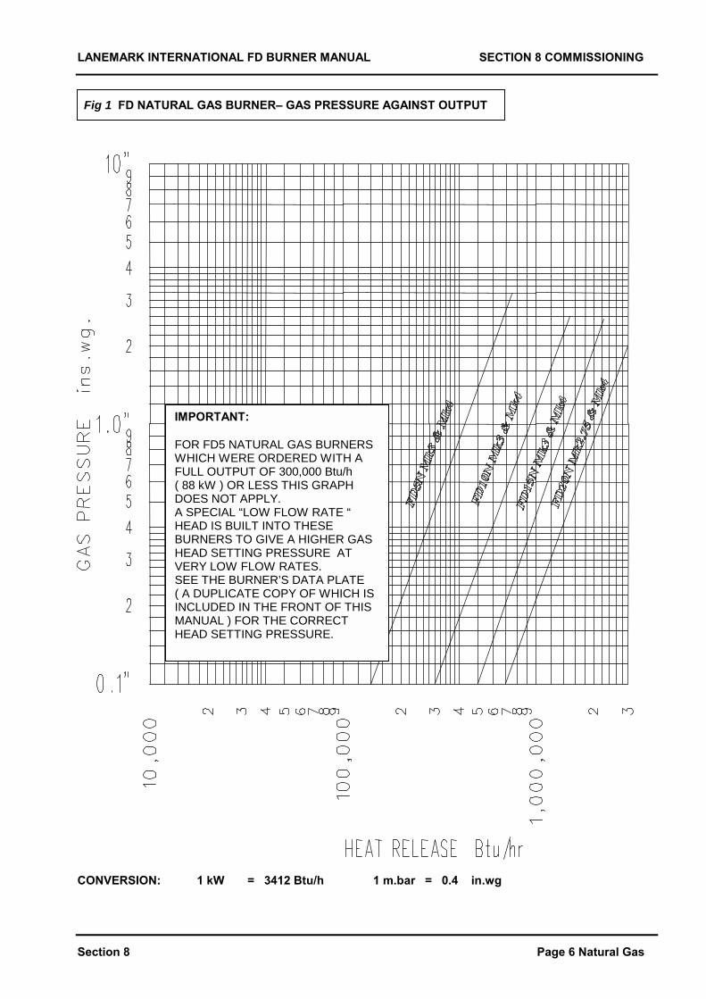
The pressure switch should be set to typically 70% of the measured air pressure or 1 mBar less than the measured air pressure. If the pressure switch is set too high then there is a possibility that nuisance lockout could occur when detecting air pressure. If the pressure switch is set too low then there is the possibility that the pressure switch would not switch the burner off if there was a problem e.g. a partially blocked flue. The pressure switch should never be set to minimum because the Satronic box times how long it takes the pressure switch to change over. If set to the minimum it changes over so quickly the box can misinterpret this as a faulty switch. A lockout code of 99 on the Satropen (an optional handheld reading device for the box) shows that this is the case. The Satronic box will not reset from this lockout. An air pressure switch must never be set too low to sacrifice safety for reliability. 12. Fit a differential manometer to the air pressure test points. With the burner running to the air prepurge stage the pressure switch should be turned up to test that the air pressure switch prevents the burner from firing and that it locks out after about 1 minute. (The standard switch has a range from 0.4 - 3.0 mBar and if the pressure is greater than 3.0 mBar lockout will not occur. Place a sheet of paper over half of the air inlet to mimic loss of pressure). 13. With the burner running the pressure switch should be turned up and the burner should lockout due to loss of the air pressure signal. 14. With the burner running turn off the main gas isolating cock and check that the burner locks out due to loss of flame signal. 15. With the burner running in main flame the inlet gas pressure should be checked to ensure it is within specification :- Natural Gas 35 mBar (14 in.wg) maximum 20 mBar ( 8 in.wg) minimum and typical Propane Gas 50 mBar (20 in.wg) maximum 35 mBar (14 in.wg) minimum and typical If the inlet pressure is above the maximum an additional regulator must be fitted. If the inlet pressure is below the minimum then the local Gas Supply Authority should be contacted to establish the cause. If the inlet pressure is unstable (the pressure may fall at times of peak demand), then as the burner has been commissioned relative to the standard inlet pressures, problems may well occur during periods of low pressure.
On Propane systems overpressure cut out with vents and under pressure cut out devices must be fitted. The settings of these should be checked for suitability and recorded. If low inlet and high outlet gas pressure switches have been fitted these should be set and their operation checked. A low inlet gas pressure switch will be set to 5 mBar below the minimum inlet pressure specified above. A high outlet gas pressure switch should typically be set to 3 mBar above the normal high fire gas pressure. The slow opening adjuster on the main gas valve (if fitted) may need adjusting to slow the opening down or a pressure pulse may occur on normal opening and trip the pressure switch. Modulating Motors 16. If a modulating motor is fitted to a ball valve the motor end stop must be set so that when it is at its fullest closed position, there is still sufficient gas flow, to light reliably and sustain a stable flame. The temperature controller should be set and the correct response of the modulating motor to the control signal should be checked. See the Data Sheet on the motor that will be contained in this manual. Final Checks 17. Check the operation of any mechanical or electronic temperature controllers. Record the set points and for electronic temperature controllers record the set-up parameters. Generally the burner should not be called to start more than 6 times an hour and should not switch from high flame to pilot / low flame more than 60 times an hour. 18. Check that there is adequate ventilation for safe combustion as given under design considerations previously. 19. The owner/operator of the burner system should be instructed in the basic operation of the burner and its controls. FINALLY replace all pressure test points and complete a commissioning form similar to the sample contained in this manual. IMPORTANT: IF FOR ANY REASON THE COMMISSIONING HAS NOT BEEN FULLY COMPLETED OR IF THERE IS A PROBLEM WITH THE GAS SUPPLY , FLUE, VENTILATION OR SAFETY CONTROLS THEN THE SYSTEM SHOULD NOT BE LEFT CAPABLE OF BEING RUN. THE OWNER / OPERATOR OF THE BURNER SYSTEM SHOULD BE MADE AWARE BEFORE LEAVING SITE.
LANEMARK INTERNATIONAL FD BURNER MANUAL SECTION 8 COMMISSIONING
Section 8 Page 6 Natural Gas
Fig 1 FD NATURAL GAS BURNER– GAS PRESSURE AGAINST OUTPUT
CONVERSION: 1 kW = 3412 Btu/h 1 m.bar = 0.4 in.wg
IMPORTANT:
FOR FD5 NATURAL GAS BURNERSWHICH WERE ORDERED WITH AFULL OUTPUT OF 300,000 Btu/h( 88 kW ) OR LESS THIS GRAPHDOES NOT APPLY.A SPECIAL “LOW FLOW RATE “HEAD IS BUILT INTO THESEBURNERS TO GIVE A HIGHER GASHEAD SETTING PRESSURE ATVERY LOW FLOW RATES.SEE THE BURNER’S DATA PLATE( A DUPLICATE COPY OF WHICH ISINCLUDED IN THE FRONT OF THISMANUAL ) FOR THE CORRECTHEAD SETTING PRESSURE.
LANEMARK INTERNATIONAL FD BURNER MANUAL SECTION 8 COMMISSIONING
Section 8 Page 6 Propane Gas
Fig 2 FD PROPANE GAS BURNER – GAS PRESSURE AGAINST OUTPUT
CONVERSION:
1 kW = 3412 Btu/h 1 m.bar = 0.4 in.wg
LANEMARK INTERNATIONAL FD BURNER MANUAL SECTION 8 COMMISSIONING
Section 8 Page 7
Fig 3 FD BURNER – AIR DIFFERENTIAL PRESSURE AGAINST OUTPUT
CONVERSION:
1 kW = 3412 Btu/h 1 m.bar = 0.4 in.wg
LANEMARK INTERNATIONAL FD BURNER MANUAL SECTION 8 COMMISSIONING
Section 8 Page 8
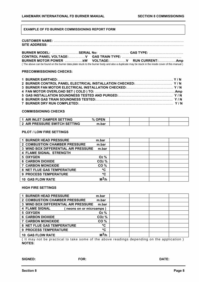
EXAMPLE OF FD BURNER COMMISSIONING REPORT FORM
CUSTOMER NAME: ………………………………………………………………………………………………………SITE ADDRESS: ………………………………………………………………………………………………………….
BURNER MODEL: ……………………SERIAL No: ……………………… GAS TYPE: ………………………….CONTROL PANEL VOLTAGE:……………V GAS TRAIN TYPE: …………………………….………………..BURNER MOTOR POWER …………….kW VOLTAGE:……………V RUN CURRENT:…………….Amp( The above can be found on the burner data plate stuck to the burner body and also a duplicate may be stuck in the inside cover of this manual )
PRECOMMISSIONING CHECKS:
1 BURNER EARTHED:………………………………………………………………………………………….. Y / N2 BURNER CONTROL PANEL ELECTRICAL INSTALLATION CHECKED:…..……………………….. Y / N3 BURNER FAN MOTOR ELECTRICAL INSTALLATION CHECKED:…………………………………… Y / N4 FAN MOTOR OVERLOAD SET ( COLD ) TO: ………………………………………………………………Amp5 GAS INSTALLATION SOUNDNESS TESTED AND PURGED:…………………………………………. Y / N6 BURNER GAS TRAIN SOUNDNESS TESTED:…………………………………………………………… Y / N7 BURNER DRY RUN COMPLETED:…………………………………………………………………………. Y / N
COMMISSIONING CHECKS
1 AIR INLET DAMPER SETTING % OPEN2 AIR PRESSURE SWITCH SETTING m.bar
PILOT / LOW FIRE SETTINGS
1 BURNER HEAD PRESSURE m.bar2 COMBUSTION CHAMBER PRESSURE m.bar3 WIND BOX DIFFERENTIAL AIR PRESSURE m.bar4 FLAME SIGNAL STRENGTH5 OXYGEN O2 %6 CARBON DIOXIDE CO2 %7 CARBON MONOXIDE CO %8 NET FLUE GAS TEMPERATURE °°°°C9 PROCESS TEMPERATURE °°°°C10 GAS FLOW RATE M3/h
HIGH FIRE SETTINGS
1 BURNER HEAD PRESSURE m.bar2 COMBUSTION CHAMBER PRESSURE m.bar3 WIND BOX DIFFERENTIAL AIR PRESSURE m.bar4 FLAME SIGNAL ( neons on or microamps )5 OXYGEN O2 %6 CARBON DIOXIDE CO2 %7 CARBON MONOXIDE CO %8 NET FLUE GAS TEMPERATURE °°°°C9 PROCESS TEMPERATURE °°°°C10 GAS FLOW RATE M3/h( I t may not be pract ical to take some of the above readings depending on the appl icat ion )NOTES:
SIGNED: FOR: DATE:
LANEMARK INTERNATIONAL FD MANUAL SECTION 8 COMMISSIONING
Section 8 Page 9
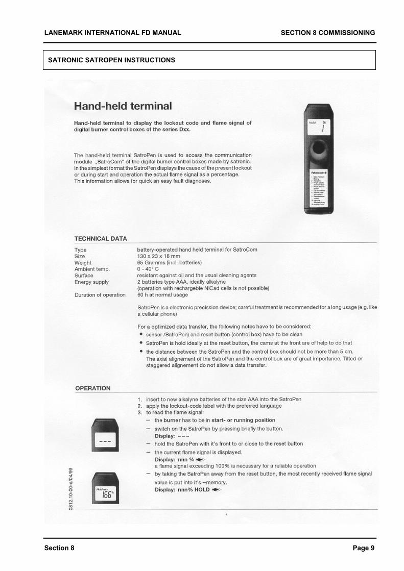
SATRONIC SATROPEN INSTRUCTIONS
LANEMARK INTERNATIONAL FD MANUAL SECTION 8 COMMISSIONING
Section 8 Page 10
LANEMARK INTERNATIONAL FD BURNER MANUAL SECTION 9 MAINTENANCE
Section 9 Page 1
SECTION 9 MAINTENANCE
LANEMARK INTERNATIONAL FD BURNER MANUAL SECTION 9 MAINTENANCE
Section 9 Page 2
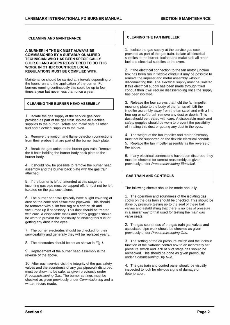
CLEANING AND MAINTENANCE A BURNER IN THE UK MUST ALWAYS BE COMMISSIONED BY A SUITABLY QUALIFIED TECHNICIAN WHO HAS BEEN SPECIFICALLY C.O.R.G.I AND ACOPS REGISTERED TO DO THIS WORK. IN OTHER COUNTRIES LOCAL REGULATIONS MUST BE COMPLIED WITH. Maintenance should be carried at intervals depending on the hours run and the application of the burner. For burners running continuously this could be up to four times a year but never less than once a year. CLEANING THE BURNER HEAD ASSEMBLY 1. Isolate the gas supply at the service gas cock provided as part of the gas train. Isolate all electrical supplies to the burner. Isolate and make safe all other fuel and electrical supplies to the oven. 2. Remove the ignition and flame detection connections from their probes that are part of the burner back plate. 3. Break the gas union to the burner gas train. Remove the 8 bolts holding the burner body back plate to the burner body. 4. It should now be possible to remove the burner head assembly and the burner back plate with the gas train attached. 5. If the burner is left unattended at this stage the incoming gas pipe must be capped off. It must not be left isolated on the gas cock alone. 6. The burner head will typically have a light covering of dust on the cone and associated pipework. This should be removed with a lint free rag or a soft brush and vacuumed up if necessary. This dust should be treated with care. A disposable mask and safety goggles should be worn to prevent the possibility of inhaling this dust or getting any dust in the eyes. 7. The burner electrodes should be checked for their serviceability and generally they will be replaced yearly. 8. The electrodes should be set as shown in Fig 1. 9. Replacement of the burner head assembly is the reverse of the above. 10. After each service visit the integrity of the gas safety valves and the soundness of any gas pipework disturbed must be shown to be safe, as given previously under Precommissioning Gas. The burner settings must be checked as given previously under Commissioning and a written record made.
CLEANING THE FAN IMPELLER 1. Isolate the gas supply at the service gas cock provided as part of the gas train. Isolate all electrical supplies to the burner. Isolate and make safe all other fuel and electrical supplies to the oven. 2. If the electrical connection to the fan motor junction box has been run in flexible conduit it may be possible to remove the impeller and motor assembly without disconnecting this. The electrical supply must be isolated. If this electrical supply has been made through fixed conduit then it will require disassembling once the supply has been isolated. 3. Release the four screws that hold the fan impeller mounting plate to the body of the fan scroll. Lift the impeller assembly away from the fan scroll and with a lint free rag or soft brush remove any dust or debris. This dust should be treated with care. A disposable mask and safety goggles should be worn to prevent the possibility of inhaling this dust or getting any dust in the eyes. 4. The weight of the fan impeller and motor assembly must not be supported on the flexible electrical conduit. 5. Replace the fan impeller assembly as the reverse of the above. 6. If any electrical connections have been disturbed they must be checked for correct reassembly as given previously under Precommissioning Electrical. GAS TRAIN AND CONTROLS The following checks should be made annually. 1. The operation and soundness of the isolating gas cocks on the gas train should be checked. This should be done by pressure testing up to the seal of these ball valves and establishing that there is no loss of pressure in a similar way to that used for testing the main gas valve seats. 2. The gas soundness of the gas train gas valves and associated pipe work should be checked as given previously under Precommissioning Gas. 3. The setting of the air pressure switch and the lockout function of the Satronic control box to an incorrectly set pressure switch and lack of pilot stage gas should be rechecked. This should be done as given previously under Commissioning Dry Run. 4. The gas train and control panel should be visually inspected to look for obvious signs of damage or deterioration.
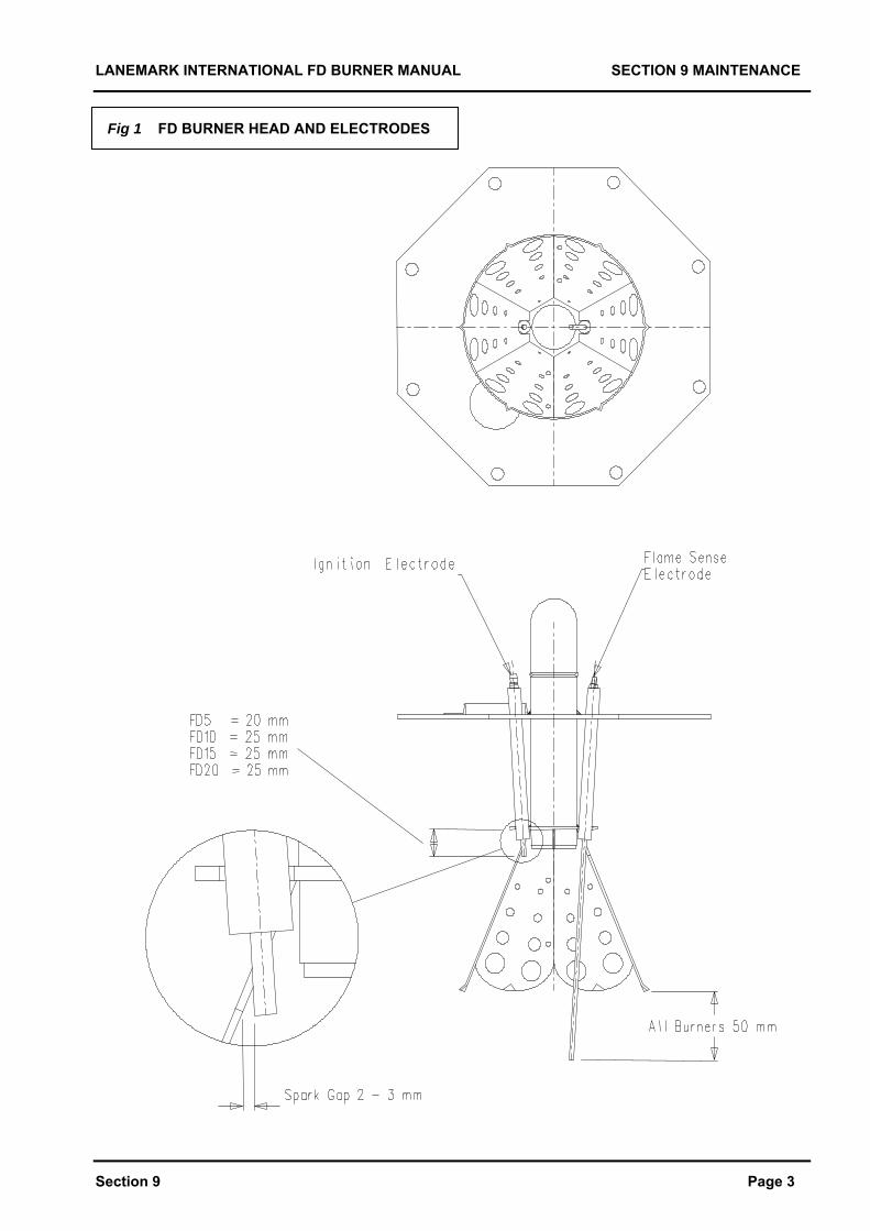
LANEMARK INTERNATIONAL FD BURNER MANUAL SECTION 9 MAINTENANCE
Section 9 Page 3
Fig 1 FD BURNER HEAD AND ELECTRODES
LANEMARK INTERNATIONAL FD BURNER MANUAL SECTION 10 FAULT FINDING
Section 10 Page 1
SECTION 10 FAULT FINDING
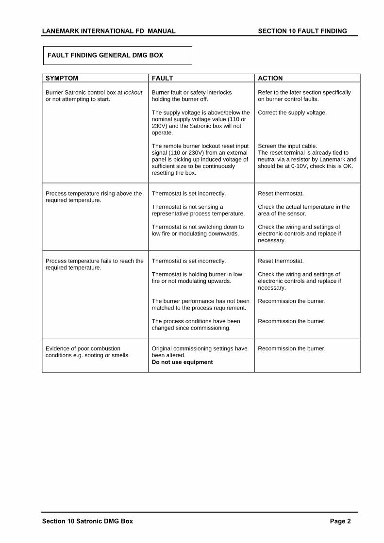
LANEMARK INTERNATIONAL FD MANUAL SECTION 10 FAULT FINDING
Section 10 Satronic DMG Box Page 2
FAULT FINDING GENERAL DMG BOX SYMPTOM FAULT ACTION Burner Satronic control box at lockout or not attempting to start.
Burner fault or safety interlocks holding the burner off. The supply voltage is above/below the nominal supply voltage value (110 or 230V) and the Satronic box will not operate. The remote burner lockout reset input signal (110 or 230V) from an external panel is picking up induced voltage of sufficient size to be continuously resetting the box.
Refer to the later section specifically on burner control faults. Correct the supply voltage. Screen the input cable. The reset terminal is already tied to neutral via a resistor by Lanemark and should be at 0-10V, check this is OK.
Process temperature rising above the required temperature.
Thermostat is set incorrectly. Thermostat is not sensing a representative process temperature. Thermostat is not switching down to low fire or modulating downwards.
Reset thermostat. Check the actual temperature in the area of the sensor. Check the wiring and settings of electronic controls and replace if necessary.
Process temperature fails to reach the required temperature.
Thermostat is set incorrectly. Thermostat is holding burner in low fire or not modulating upwards. The burner performance has not been matched to the process requirement. The process conditions have been changed since commissioning.
Reset thermostat. Check the wiring and settings of electronic controls and replace if necessary. Recommission the burner. Recommission the burner.
Evidence of poor combustion conditions e.g. sooting or smells.
Original commissioning settings have been altered. Do not use equipment
Recommission the burner.

LANEMARK INTERNATIONAL FD MANUAL SECTION 10 FAULT FINDING
Section 10 Satronic DMG Box Page 2
FAULT FINDING TEMPERATURE CONTROLLERS SYMPTOM FAULT ACTION Burner runs to ignition and the temperature controller switches the burner off and it attempts to cycle again.
The ignition spark is interfering with the electronics of the temperature controller.
Check that the ignition spark plug cap is an original part or replacement and suppressed with a 5 kilo ohm resistor.
FAULT FINDING GAS VALVES SYMPTOM FAULT ACTION 1st valve or governor will not open.
High pressure gas trapped between 1st and 2nd main valve seats and locking up 1st valve.
Remove test point between seats. Tap valve to release 1st valve seat. Open up by-pass valve to allow more gas to flow.
2nd main valve not opening.
The throughput restrictor has been fully or almost fully closed. The slow opening adjuster is set to the slowest opening.
Open up the through put restrictor and increase the speed of lift of the slow opening adjuster.
No pilot/start gas.
The adjuster on the pilot / start gas valve closed or nearly fully closed.
Use the adjuster to increase the pilot/start gas flow.
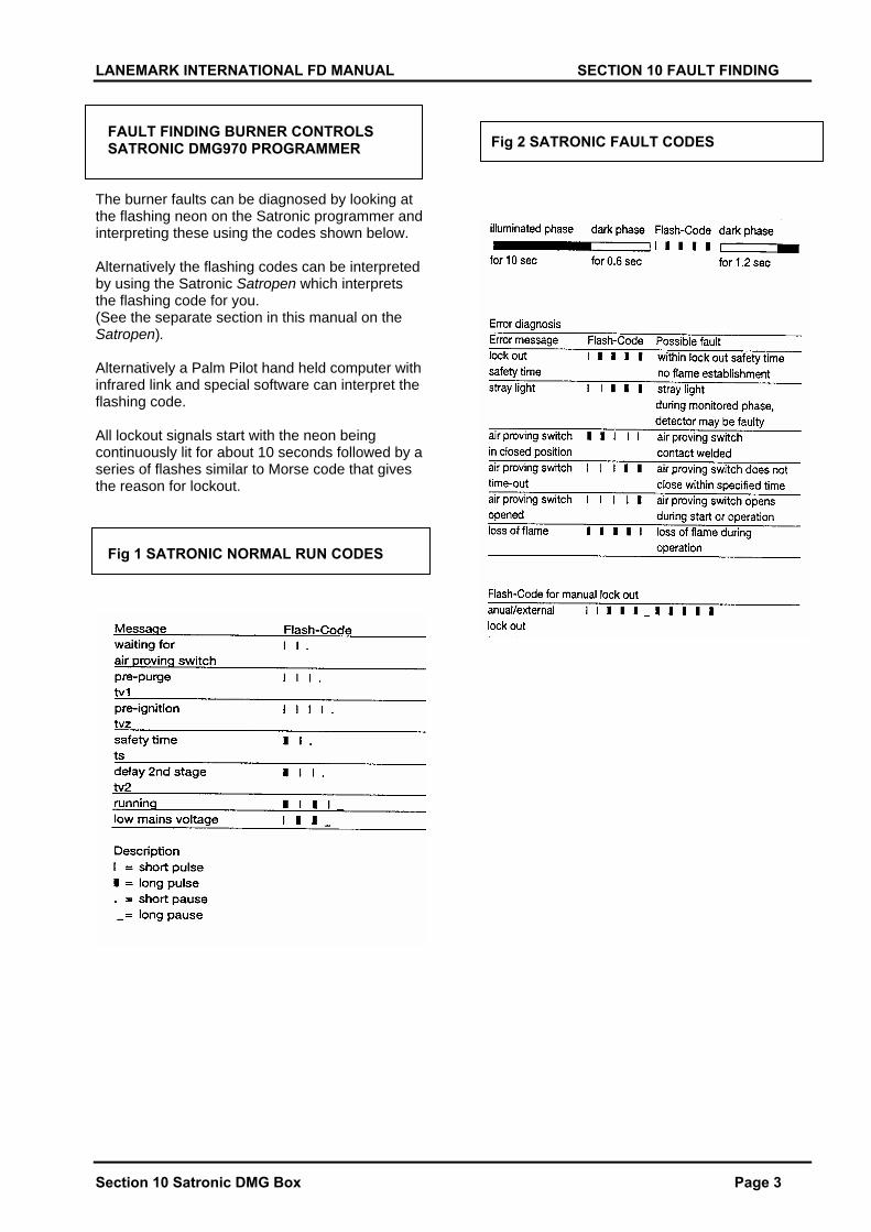
LANEMARK INTERNATIONAL FD MANUAL SECTION 10 FAULT FINDING
Section 10 Satronic DMG Box Page 3
FAULT FINDING BURNER CONTROLS SATRONIC DMG970 PROGRAMMER The burner faults can be diagnosed by looking at the flashing neon on the Satronic programmer and interpreting these using the codes shown below. Alternatively the flashing codes can be interpreted by using the Satronic Satropen which interprets the flashing code for you. (See the separate section in this manual on the Satropen). Alternatively a Palm Pilot hand held computer with infrared link and special software can interpret the flashing code. All lockout signals start with the neon being continuously lit for about 10 seconds followed by a series of flashes similar to Morse code that gives the reason for lockout. Fig 1 SATRONIC NORMAL RUN CODES
Fig 2 SATRONIC FAULT CODES
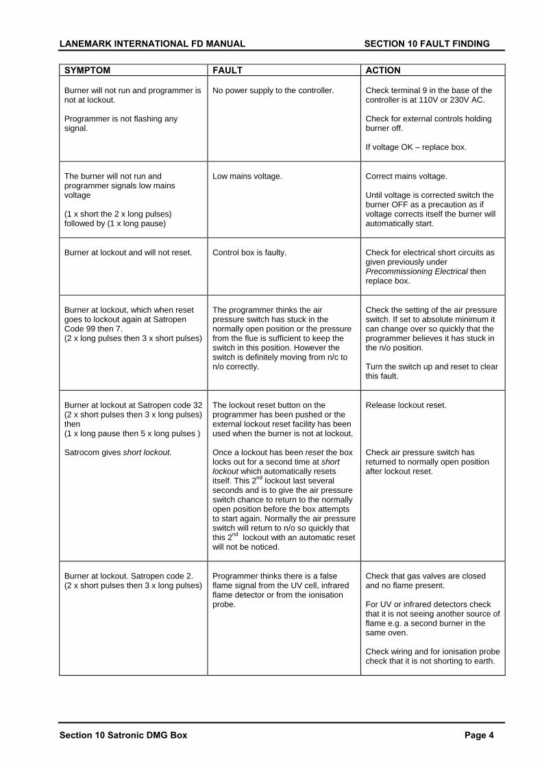
LANEMARK INTERNATIONAL FD MANUAL SECTION 10 FAULT FINDING
Section 10 Satronic DMG Box Page 4
SYMPTOM FAULT ACTION Burner will not run and programmer is not at lockout. Programmer is not flashing any signal.
No power supply to the controller.
Check terminal 9 in the base of the controller is at 110V or 230V AC. Check for external controls holding burner off. If voltage OK – replace box.
The burner will not run and programmer signals low mains voltage (1 x short the 2 x long pulses) followed by (1 x long pause)
Low mains voltage.
Correct mains voltage. Until voltage is corrected switch the burner OFF as a precaution as if voltage corrects itself the burner will automatically start.
Burner at lockout and will not reset.
Control box is faulty.
Check for electrical short circuits as given previously under Precommissioning Electrical then replace box.
Burner at lockout, which when reset goes to lockout again at Satropen Code 99 then 7. (2 x long pulses then 3 x short pulses)
The programmer thinks the air pressure switch has stuck in the normally open position or the pressure from the flue is sufficient to keep the switch in this position. However the switch is definitely moving from n/c to n/o correctly.
Check the setting of the air pressure switch. If set to absolute minimum it can change over so quickly that the programmer believes it has stuck in the n/o position. Turn the switch up and reset to clear this fault.
Burner at lockout at Satropen code 32 (2 x short pulses then 3 x long pulses) then (1 x long pause then 5 x long pulses ) Satrocom gives short lockout.
The lockout reset button on the programmer has been pushed or the external lockout reset facility has been used when the burner is not at lockout. Once a lockout has been reset the box locks out for a second time at short lockout which automatically resets itself. This 2nd lockout last several seconds and is to give the air pressure switch chance to return to the normally open position before the box attempts to start again. Normally the air pressure switch will return to n/o so quickly that this 2nd lockout with an automatic reset will not be noticed.
Release lockout reset. Check air pressure switch has returned to normally open position after lockout reset.
Burner at lockout. Satropen code 2. (2 x short pulses then 3 x long pulses)
Programmer thinks there is a false flame signal from the UV cell, infrared flame detector or from the ionisation probe.
Check that gas valves are closed and no flame present. For UV or infrared detectors check that it is not seeing another source of flame e.g. a second burner in the same oven. Check wiring and for ionisation probe check that it is not shorting to earth.
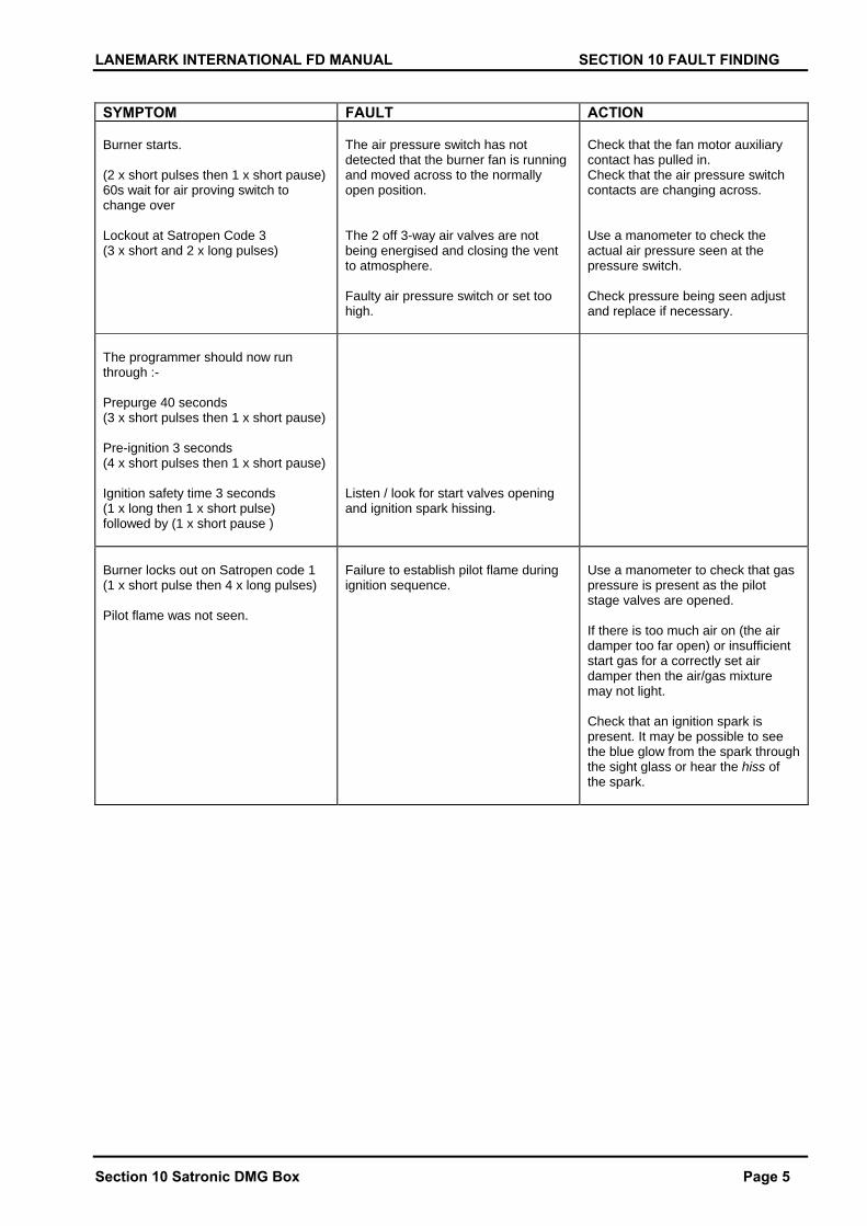
LANEMARK INTERNATIONAL FD MANUAL SECTION 10 FAULT FINDING
Section 10 Satronic DMG Box Page 5
SYMPTOM FAULT ACTION Burner starts. (2 x short pulses then 1 x short pause) 60s wait for air proving switch to change over Lockout at Satropen Code 3 (3 x short and 2 x long pulses)
The air pressure switch has not detected that the burner fan is running and moved across to the normally open position. The 2 off 3-way air valves are not being energised and closing the vent to atmosphere. Faulty air pressure switch or set too high.
Check that the fan motor auxiliary contact has pulled in. Check that the air pressure switch contacts are changing across. Use a manometer to check the actual air pressure seen at the pressure switch. Check pressure being seen adjust and replace if necessary.
The programmer should now run through :- Prepurge 40 seconds (3 x short pulses then 1 x short pause) Pre-ignition 3 seconds (4 x short pulses then 1 x short pause) Ignition safety time 3 seconds (1 x long then 1 x short pulse) followed by (1 x short pause )
Listen / look for start valves opening and ignition spark hissing.
Burner locks out on Satropen code 1 (1 x short pulse then 4 x long pulses) Pilot flame was not seen.
Failure to establish pilot flame during ignition sequence.
Use a manometer to check that gas pressure is present as the pilot stage valves are opened. If there is too much air on (the air damper too far open) or insufficient start gas for a correctly set air damper then the air/gas mixture may not light. Check that an ignition spark is present. It may be possible to see the blue glow from the spark through the sight glass or hear the hiss of the spark.
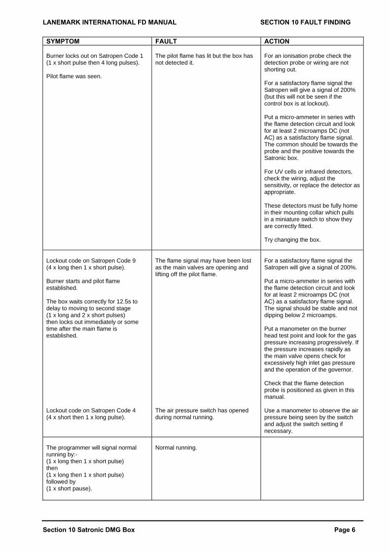
LANEMARK INTERNATIONAL FD MANUAL SECTION 10 FAULT FINDING
Section 10 Satronic DMG Box Page 6
SYMPTOM FAULT ACTION Burner locks out on Satropen Code 1 (1 x short pulse then 4 long pulses). Pilot flame was seen.
The pilot flame has lit but the box has not detected it.
For an ionisation probe check the detection probe or wiring are not shorting out. For a satisfactory flame signal the Satropen will give a signal of 200% (but this will not be seen if the control box is at lockout). Put a micro-ammeter in series with the flame detection circuit and look for at least 2 microamps DC (not AC) as a satisfactory flame signal. The common should be towards the probe and the positive towards the Satronic box. For UV cells or infrared detectors, check the wiring, adjust the sensitivity, or replace the detector as appropriate. These detectors must be fully home in their mounting collar which pulls in a miniature switch to show they are correctly fitted. Try changing the box.
Lockout code on Satropen Code 9 (4 x long then 1 x short pulse). Burner starts and pilot flame established. The box waits correctly for 12.5s to delay to moving to second stage (1 x long and 2 x short pulses) then locks out immediately or some time after the main flame is established. Lockout code on Satropen Code 4 (4 x short then 1 x long pulse).
The flame signal may have been lost as the main valves are opening and lifting off the pilot flame. The air pressure switch has opened during normal running.
For a satisfactory flame signal the Satropen will give a signal of 200%. Put a micro-ammeter in series with the flame detection circuit and look for at least 2 microamps DC (not AC) as a satisfactory flame signal. The signal should be stable and not dipping below 2 microamps. Put a manometer on the burner head test point and look for the gas pressure increasing progressively. If the pressure increases rapidly as the main valve opens check for excessively high inlet gas pressure and the operation of the governor. Check that the flame detection probe is positioned as given in this manual. Use a manometer to observe the air pressure being seen by the switch and adjust the switch setting if necessary.
The programmer will signal normal running by:- (1 x long then 1 x short pulse) then (1 x long then 1 x short pulse) followed by (1 x short pause).
Normal running.
LANEMARK INTERNATIONAL FD MANUAL SECTION 10 FAULT FINDING
Section 10 Page 7
NOTE: If the fault persists and the cause cannot be isolated, contact Lanemark International Ltd to arrange for a visit by one of our Service Engineers. Lanemark International Ltd, Whitacre Rd, Nuneaton, Warwickshire. CV11 6BW Tel: 024 7635 2000 Fax: 024 7634 1166 Tel Int: + 44 (0) 24 7635 2000 Fax Int: + 44 (0) 24 7634 1166 Web site : http://www.lanemark.com e-mail : [email protected]
LANEMARK INTERNATIONAL FD BURNER MANUAL SECTION 11 COMPONENT REPLACEMENT
Section 11 Page 1
SECTION 11 COMPONENT REPLACEMENT
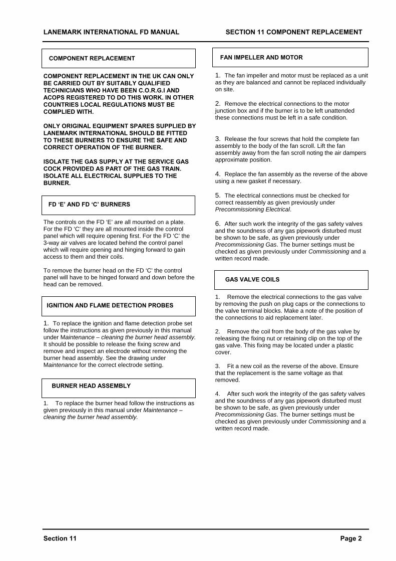
LANEMARK INTERNATIONAL FD MANUAL SECTION 11 COMPONENT REPLACEMENT
Section 11 Page 2
COMPONENT REPLACEMENT
COMPONENT REPLACEMENT IN THE UK CAN ONLY BE CARRIED OUT BY SUITABLY QUALIFIED TECHNICIANS WHO HAVE BEEN C.O.R.G.I AND ACOPS REGISTERED TO DO THIS WORK. IN OTHER COUNTRIES LOCAL REGULATIONS MUST BE COMPLIED WITH. ONLY ORIGINAL EQUIPMENT SPARES SUPPLIED BY LANEMARK INTERNATIONAL SHOULD BE FITTED TO THESE BURNERS TO ENSURE THE SAFE AND CORRECT OPERATION OF THE BURNER. ISOLATE THE GAS SUPPLY AT THE SERVICE GAS COCK PROVIDED AS PART OF THE GAS TRAIN. ISOLATE ALL ELECTRICAL SUPPLIES TO THE BURNER. FD ‘E’ AND FD ‘C’ BURNERS
The controls on the FD ‘E’ are all mounted on a plate. For the FD ‘C’ they are all mounted inside the control panel which will require opening first. For the FD ‘C’ the 3-way air valves are located behind the control panel which will require opening and hinging forward to gain access to them and their coils. To remove the burner head on the FD ‘C’ the control panel will have to be hinged forward and down before the head can be removed. IGNITION AND FLAME DETECTION PROBES
1. To replace the ignition and flame detection probe set follow the instructions as given previously in this manual under Maintenance – cleaning the burner head assembly. It should be possible to release the fixing screw and remove and inspect an electrode without removing the burner head assembly. See the drawing under Maintenance for the correct electrode setting. BURNER HEAD ASSEMBLY
1. To replace the burner head follow the instructions as given previously in this manual under Maintenance – cleaning the burner head assembly.
FAN IMPELLER AND MOTOR
1. The fan impeller and motor must be replaced as a unit as they are balanced and cannot be replaced individually on site. 2. Remove the electrical connections to the motor junction box and if the burner is to be left unattended these connections must be left in a safe condition. 3. Release the four screws that hold the complete fan assembly to the body of the fan scroll. Lift the fan assembly away from the fan scroll noting the air dampers approximate position. 4. Replace the fan assembly as the reverse of the above using a new gasket if necessary. 5. The electrical connections must be checked for correct reassembly as given previously under Precommissioning Electrical. 6. After such work the integrity of the gas safety valves and the soundness of any gas pipework disturbed must be shown to be safe, as given previously under Precommissioning Gas. The burner settings must be checked as given previously under Commissioning and a written record made. GAS VALVE COILS
1. Remove the electrical connections to the gas valve by removing the push on plug caps or the connections to the valve terminal blocks. Make a note of the position of the connections to aid replacement later. 2. Remove the coil from the body of the gas valve by releasing the fixing nut or retaining clip on the top of the gas valve. This fixing may be located under a plastic cover. 3. Fit a new coil as the reverse of the above. Ensure that the replacement is the same voltage as that removed. 4. After such work the integrity of the gas safety valves and the soundness of any gas pipework disturbed must be shown to be safe, as given previously under Precommissioning Gas. The burner settings must be checked as given previously under Commissioning and a written record made.
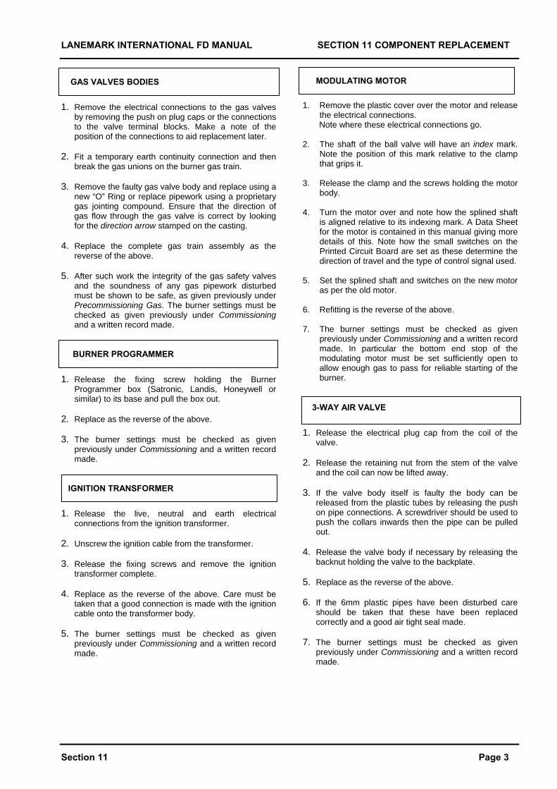
LANEMARK INTERNATIONAL FD MANUAL SECTION 11 COMPONENT REPLACEMENT
Section 11 Page 3
GAS VALVES BODIES
1. Remove the electrical connections to the gas valves by removing the push on plug caps or the connections to the valve terminal blocks. Make a note of the position of the connections to aid replacement later.
2. Fit a temporary earth continuity connection and then
break the gas unions on the burner gas train. 3. Remove the faulty gas valve body and replace using a
new “O” Ring or replace pipework using a proprietary gas jointing compound. Ensure that the direction of gas flow through the gas valve is correct by looking for the direction arrow stamped on the casting.
4. Replace the complete gas train assembly as the
reverse of the above. 5. After such work the integrity of the gas safety valves
and the soundness of any gas pipework disturbed must be shown to be safe, as given previously under Precommissioning Gas. The burner settings must be checked as given previously under Commissioning and a written record made.
BURNER PROGRAMMER
1. Release the fixing screw holding the Burner Programmer box (Satronic, Landis, Honeywell or similar) to its base and pull the box out.
2. Replace as the reverse of the above. 3. The burner settings must be checked as given
previously under Commissioning and a written record made.
IGNITION TRANSFORMER
1. Release the live, neutral and earth electrical connections from the ignition transformer.
2. Unscrew the ignition cable from the transformer. 3. Release the fixing screws and remove the ignition
transformer complete. 4. Replace as the reverse of the above. Care must be
taken that a good connection is made with the ignition cable onto the transformer body.
5. The burner settings must be checked as given
previously under Commissioning and a written record made.
MODULATING MOTOR
1. Remove the plastic cover over the motor and release the electrical connections.
Note where these electrical connections go. 2. The shaft of the ball valve will have an index mark.
Note the position of this mark relative to the clamp that grips it.
3. Release the clamp and the screws holding the motor
body. 4. Turn the motor over and note how the splined shaft
is aligned relative to its indexing mark. A Data Sheet for the motor is contained in this manual giving more details of this. Note how the small switches on the Printed Circuit Board are set as these determine the direction of travel and the type of control signal used.
5. Set the splined shaft and switches on the new motor
as per the old motor. 6. Refitting is the reverse of the above. 7. The burner settings must be checked as given
previously under Commissioning and a written record made. In particular the bottom end stop of the modulating motor must be set sufficiently open to allow enough gas to pass for reliable starting of the burner.
3-WAY AIR VALVE
1. Release the electrical plug cap from the coil of the valve.
2. Release the retaining nut from the stem of the valve
and the coil can now be lifted away. 3. If the valve body itself is faulty the body can be
released from the plastic tubes by releasing the push on pipe connections. A screwdriver should be used to push the collars inwards then the pipe can be pulled out.
4. Release the valve body if necessary by releasing the
backnut holding the valve to the backplate. 5. Replace as the reverse of the above. 6. If the 6mm plastic pipes have been disturbed care
should be taken that these have been replaced correctly and a good air tight seal made.
7. The burner settings must be checked as given
previously under Commissioning and a written record made.
LANEMARK INTERNATIONAL FD MANUAL SECTION 11 COMPONENT REPLACEMENT
Section 11 Page 3
AIR PRESSURE SWITCH 1. Remove the plastic cover over the pressure switch
and release the electrical connections and the switch fixing screws.
2. Replace as the reverse of the above. 3. The burner settings must be checked as given
previously under Commissioning and a written record made.
LANEMARK INTERNATIONAL FD BURNER MANUAL SECTION 12 SPECIAL FEATURES
Section 12 Page 1
SECTION 12 SPECIAL FEATURES If any Special Features were designed and supplied with a burner details will be contained in this section. This could be Data Sheets for special components and additional operating and commissioning instructions.
LANEMARK INTERNATIONAL FD BURNER MANUAL SECTION 12 SPECIAL FEATURES
Section 12 Job Unique Special Features
Job No. J
LANEMARK INTERNATIONAL FD BURNER MANUAL SECTION 13 RECOMMENDED SPARES
Section 13 Page 1
SECTION 13 RECOMMENDED SPARES If this manual was sent out with a burner then the Recommended Spares list will be contained in this section of the manual for the burner and any accessories e.g. Temperature Controllers.
LANEMARK INTERNATIONAL FD BURNER MANUAL SECTION 14 HEALTH AND SAFETY
Section 14 Page 1
SECTION 14 HEALTH AND SAFETY
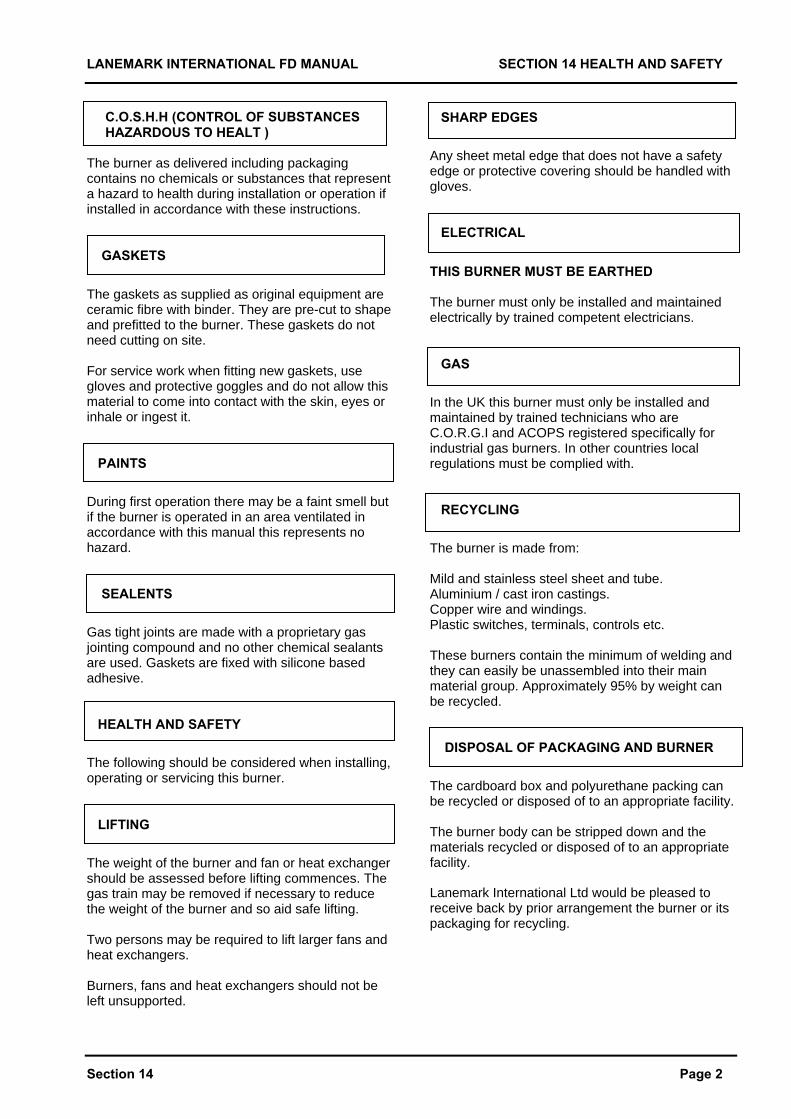
LANEMARK INTERNATIONAL FD MANUAL SECTION 14 HEALTH AND SAFETY
Section 14 Page 2
C.O.S.H.H (CONTROL OF SUBSTANCES HAZARDOUS TO HEALT ) The burner as delivered including packaging contains no chemicals or substances that represent a hazard to health during installation or operation if installed in accordance with these instructions. GASKETS The gaskets as supplied as original equipment are ceramic fibre with binder. They are pre-cut to shape and prefitted to the burner. These gaskets do not need cutting on site. For service work when fitting new gaskets, use gloves and protective goggles and do not allow this material to come into contact with the skin, eyes or inhale or ingest it. PAINTS
During first operation there may be a faint smell but if the burner is operated in an area ventilated in accordance with this manual this represents no hazard. SEALENTS
Gas tight joints are made with a proprietary gas jointing compound and no other chemical sealants are used. Gaskets are fixed with silicone based adhesive. HEALTH AND SAFETY
The following should be considered when installing, operating or servicing this burner. LIFTING
The weight of the burner and fan or heat exchanger should be assessed before lifting commences. The gas train may be removed if necessary to reduce the weight of the burner and so aid safe lifting. Two persons may be required to lift larger fans and heat exchangers. Burners, fans and heat exchangers should not be left unsupported.
SHARP EDGES
Any sheet metal edge that does not have a safety edge or protective covering should be handled with gloves. ELECTRICAL
THIS BURNER MUST BE EARTHED The burner must only be installed and maintained electrically by trained competent electricians. GAS
In the UK this burner must only be installed and maintained by trained technicians who are C.O.R.G.I and ACOPS registered specifically for industrial gas burners. In other countries local regulations must be complied with. RECYCLING
The burner is made from: Mild and stainless steel sheet and tube. Aluminium / cast iron castings. Copper wire and windings. Plastic switches, terminals, controls etc. These burners contain the minimum of welding and they can easily be unassembled into their main material group. Approximately 95% by weight can be recycled. DISPOSAL OF PACKAGING AND BURNER
The cardboard box and polyurethane packing can be recycled or disposed of to an appropriate facility. The burner body can be stripped down and the materials recycled or disposed of to an appropriate facility. Lanemark International Ltd would be pleased to receive back by prior arrangement the burner or its packaging for recycling.
LANEMARK INTERNATIONAL FD BURNER MANUAL SECTION 15 NOTES
Section 15 Page 1
SECTION 15 NOTES
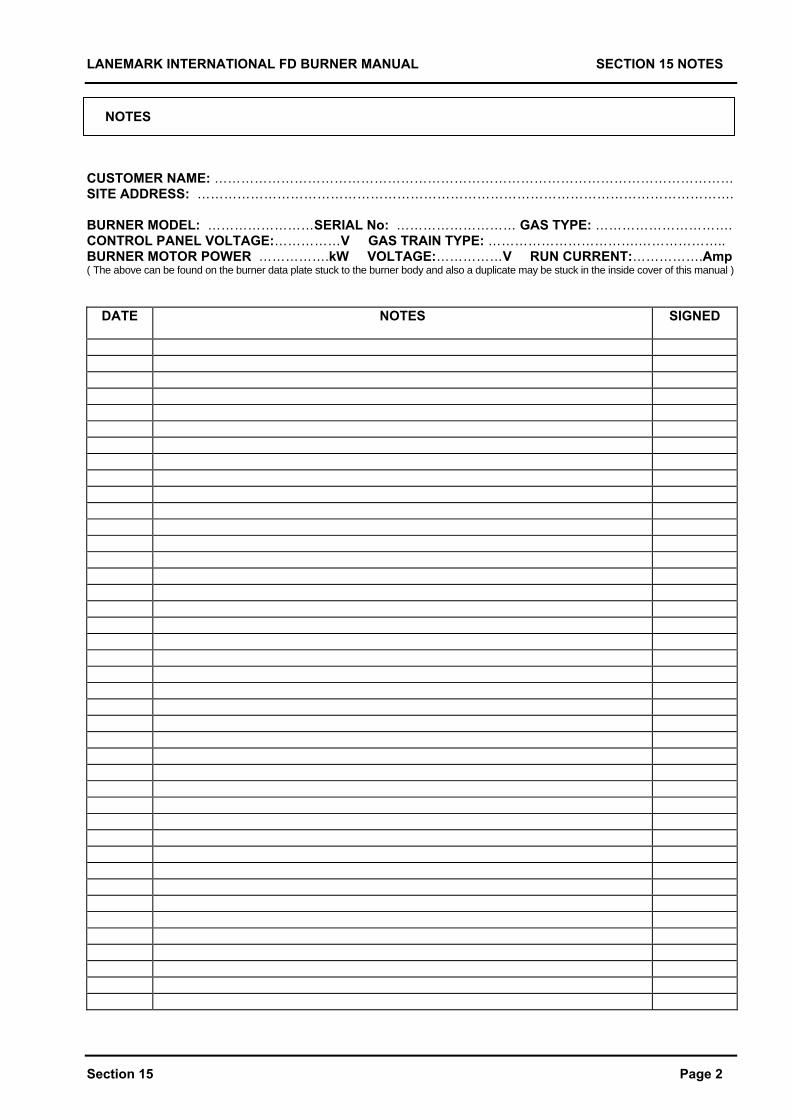
LANEMARK INTERNATIONAL FD BURNER MANUAL SECTION 15 NOTES
NOTES CUSTOMER NAME: ……………………………………………………………………………………………………… SITE ADDRESS: …………………………………………………………………………………………………………. BURNER MODEL: ……………………SERIAL No: ……………………… GAS TYPE: …………………………. CONTROL PANEL VOLTAGE:……………V GAS TRAIN TYPE: …………………………….……………….. BURNER MOTOR POWER …………….kW VOLTAGE:……………V RUN CURRENT:…………….Amp ( The above can be found on the burner data plate stuck to the burner body and also a duplicate may be stuck in the inside cover of this manual )
DATE NOTES SIGNED
Section 15 Page 2

LANEMARK INTERNATIONAL FD BURNER MANUAL
L A N E M A R K I N T E R N A T I O N A L L T D
L A N E M A R K H O U S E W H I T A C R E R D N U N E A T O N E N G L A N D C V 1 1 6 B W Tel +44 (0)24 7635 2000 Fax +44 (0)24 7634 1166 e-mail [email protected] Web Site http://www.lanemark.com
Extra copies of this manual are available at £25.00 each + VAT. Please quote the Job Number on the front.