Embed Size (px)
Citation preview
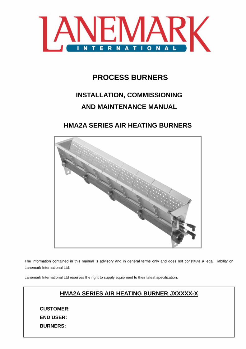
HMA2A SERIES AIR HEATING BURNERS
HMA2A SERIES AIR HEATING BURNER JXXXXX-X
CUSTOMER:
END USER:
BURNERS:
The information contained in this manual is advisory and in general terms only and does not constitute a legal liability on
Lanemark International Ltd.
Lanemark International Ltd reserves the right to supply equipment to their latest specification.
PROCESS BURNERS
INSTALLATION, COMMISSIONING
AND MAINTENANCE MANUAL

SE
CT
ION
0 C
ON
TE
NT
S
MIDCO HMA2A SERIES AIR HEATING BURNER
Section 0 Contents Page
SECTION DESCRIPTION PAGE
0 Contents Pages
0 Burner Rating Plates
0 Declaration of Conformity
0 Declaration of Incorporation
1 GENERAL DESIGN
1 Brief Burner Specification 1
1 Shipping Contents 1
1 Construction Standards 1
1 General Design Considerations 1
1 Installation 1
1 General Arrangement 1
1 Figure 1 Typical Burner Assembly - Front View 2
1 Figure 2 Typical Burner Assembly - Rear View 2
1 Figure 3 General Mounting Arrangement - Side View 3
1 Figure 4 General Mounting Arrangement - Plan View 3
1 Pull-Thru System 4
1 Figure 5 Heater Installation - Side View 4
1 Gas Supply 6
1 Figure 6 Duct Installation - Side View 4
1 Push-Thru System 5
1 Figure 7 Installation in a Push-Thru System - Side View 5
1 Duct/Elbow Considerations 5
1 Figure 8 Duct/Elbow Considerations 5
1 Applications 5
1 Gas Supply General 6
2 BURNER HEAD DESIGN
2 Lanemark Midco HMA2A Burner Head 1
2 Specifications 1
2 Figure 1 HMA2A Flame Lengths (mm) 2
2 Figure 2 HMA2A Air Pressure Drops (Pa) 2
MIDCO HMA2A SERIES AIR HEATING BURNER
Contents Page Section 0
SECTION DESCRIPTION PAGE
2 Figure 3 HMA2A Inlet Gas Pressures (mbar) 3
2 Figure 4 HMA2A Profile Velocities (m/s) 3
2 Figure 5 HMA2A Burner Head Parts - Isometric View 4
2 Figure 6 HMA2A Pilot Assembly - Mounting Details 5
3 MAINTENANCE
3 Cleaning and Maintenance 1
3 HMA2A Series Burner Head 1
4 COMPONENT REPLACEMENT
4 Component Replacement 1
4 Electrodes 1
4 HMA2A Burner Head Assembly 1
SE
CT
ION
0 C
ON
TE
NT
S
SE
CT
ION
0 B
UR
NE
R R
AT
ING
PL
AT
ES
MIDCO HMA2A SERIES AIR HEATING BURNER
Section 0 Rating Plates
SE
CT
ION
0 C
ER
TIF
ICA
TIO
N
MIDCO HMA2A SERIES AIR HEATING BURNER
Declaration of Conformity Section 0

SE
CT
ION
0 C
ER
TIF
ICA
TIO
N
MIDCO HMA2A SERIES AIR HEATING BURNER
Section 0 Declaration of Incorporation

SE
CT
ION
0 C
ER
TIF
ICA
TIO
N
MIDCO HMA2A SERIES AIR HEATING BURNER
Section 0
SE
CT
ION
1 G
EN
ER
AL
DE
SIG
N
MIDCO HMA2A SERIES AIR HEATING BURNER
Section 1
SE
CT
ION
1 G
EN
ER
AL
DE
SIG
N
MIDCO HMA2A SERIES AIR HEATING BURNER
Section 1
SE
CT
ION
1 G
EN
ER
AL
DE
SIG
N
MIDCO HMA2A SERIES AIR HEATING BURNER
Section 1 Page 1
BRIEF BURNER SPECIFICATION
Lanemark Midco HMA2A series air heating burners are designed to provide a high efficiency, high turndown, low emission solution for air replacement or “make-up” air heating applications.
The burners are available for both Natural Gas and Propane (LPG) Gas with the fuel only being modulated to achieve a maximum possible turndown ratio of 30:1 dependant on the maximum burner capacity. Short flame lengths and exceptional flame stability are achieved by the unique combustion head design.
Lanemark Midco HMA2A series burners operate directly within the heated air flow and can be located either upstream or downstream of the main circulation fan.
Lanemark Midco HMA2A series air heating burners conform with the requirements of the following documents:
ISO 9001:2008 Quality Management System
EN 746-2: 1997 Safety Standards for Combustion Systems
2006/42/EC Machinery Directive
73/23/EEC Low Voltage Directive (in the version 93/68/EEC)
EN 60204-1:2006 Safety of machinery. Electrical equipment. General requirements.
SHIPPING CONTENTS
Lanemark Midco HMA2A series air heating burners are shipped in a single heavy duty cardboard box with an infill of polyurethane foam.
CONSTRUCTION STANDARDS
Lanemark Midco HMA2A series air heating burners are generally constructed in accordance with:
EN746 Part 2: Safety Requirements for Combustion and Fuel Handling Systems of Industrial Thermoprocessing Equipment.
A Declaration of Incorporation is supplied with each burner as required by the Machinery Directive 2006/42/EC, for incorporation into other equipment/machines to constitute machinery.
GENERAL DESIGN CONSIDERATIONS
INSTALLATION
It is UK law that Lanemark Midco HMA2A series air heating burners are installed, commissioned and maintained by competent persons only, e.g. A.C.S. and GAS SAFE registered installers only. In other countries local gas regulations must be observed.
GENERAL ARRANGEMENT
For “make-up air” or “air replacement” heating applications, Lanemark Midco HMA2A series air heating burners normally operate with 100% fresh air.
For spraybooth, dryer or process oven applications, it is important that adequate fresh air is available at all times to meet the combustion requirements of the burner.
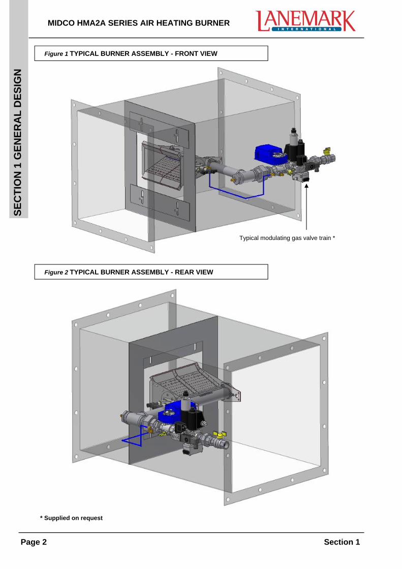
Lanemark Midco HMA2A series air heating burners should be located parallel to the main air flow in the centre of the profile area within a duct. (Any reinforcements used in the profile construction should be located on the downstream side of the profile area)
The profile plate should be constructed such that the width is fixed with adjustments incorporated above and below the burner, +/- 50mm is typical, as shown in figure 3 section 1.
SE
CT
ION
1 G
EN
ER
AL
DE
SIG
N
MIDCO HMA2A SERIES AIR HEATING BURNER
Page 2 Section 1
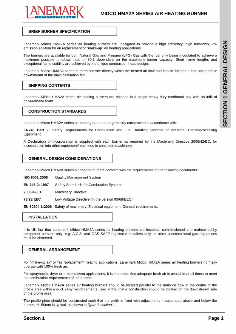
Figure 1 TYPICAL BURNER ASSEMBLY - FRONT VIEW
* Supplied on request
Figure 2 TYPICAL BURNER ASSEMBLY - REAR VIEW
Typical modulating gas valve train *
SE
CT
ION
1 G
EN
ER
AL
DE
SIG
N
MIDCO HMA2A SERIES AIR HEATING BURNER
Section 1 Page 3
Figure 3 GENERAL MOUNTING ARRANGEMENT - SIDE VIEW
Lanemark Midco HMA2A series air heating burners can be mounted horizontally or vertically.
Figure 4 GENERAL MOUNTING ARRANGEMENT - PLAN VIEW
AdjustableProfile Plate
FixedProfile Plate
Air Flow
Burner should be centered to the main circulation fan(if possible)
Profile opening shouldbe centered to the burner (if possible)
Burner should be centred
to the main air supply fan
Burner should be centred
to the profile opening
50mm Clearance
50mm Clearance
Fixed Profile Plate
Fixed Profile Plate
Adjustable Profile Plate Fixed Profile Plate
Fixed Profile Plate
Air Flow
Air Flow
Fixed Profile Plate
50mm Clearance
50mm Clearance
SE
CT
ION
1 G
EN
ER
AL
DE
SIG
N
MIDCO HMA2A SERIES AIR HEATING BURNER
Page 4 Section 1
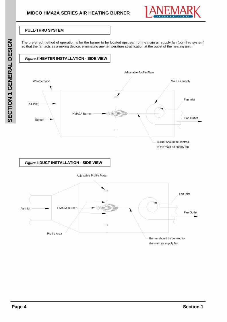
PULL-THRU SYSTEM
The preferred method of operation is for the burner to be located upstream of the main air supply fan (pull-thru system) so that the fan acts as a mixing device, eliminating any temperature stratification at the outlet of the heating unit.
Figure 5 HEATER INSTALLATION - SIDE VIEW
Air Inlet
Screen
Weatherhood
Fan Inlet
Profile PlateAdjustable
Burner
Centre BurnerTo The Fan(if possible)
Circulation Fan
HMA2A
Fan Outlet
Figure 6 DUCT INSTALLATION - SIDE VIEW
Air Inlet
Fan Inlet
Profile PlateAdjustable
Profile Area
Fan Outlet
Centre BurnerTo The Fan(if possible)
HMA2ABurner
Burner should be centred to
the main air supply fan
Main air supply
Burner should be centred
to the main air supply fan
Adjustable Profile Plate
Adjustable Profile Plate
Fan Inlet
Fan Inlet
Fan Outlet
Weatherhood
Air Inlet
Screen
Air Inlet
Profile Area
HMA2A Burner
HMA2A Burner
Fan Outlet
SE
CT
ION
1 G
EN
ER
AL
DE
SIG
N
MIDCO HMA2A SERIES AIR HEATING BURNER
Section 1 Page 5
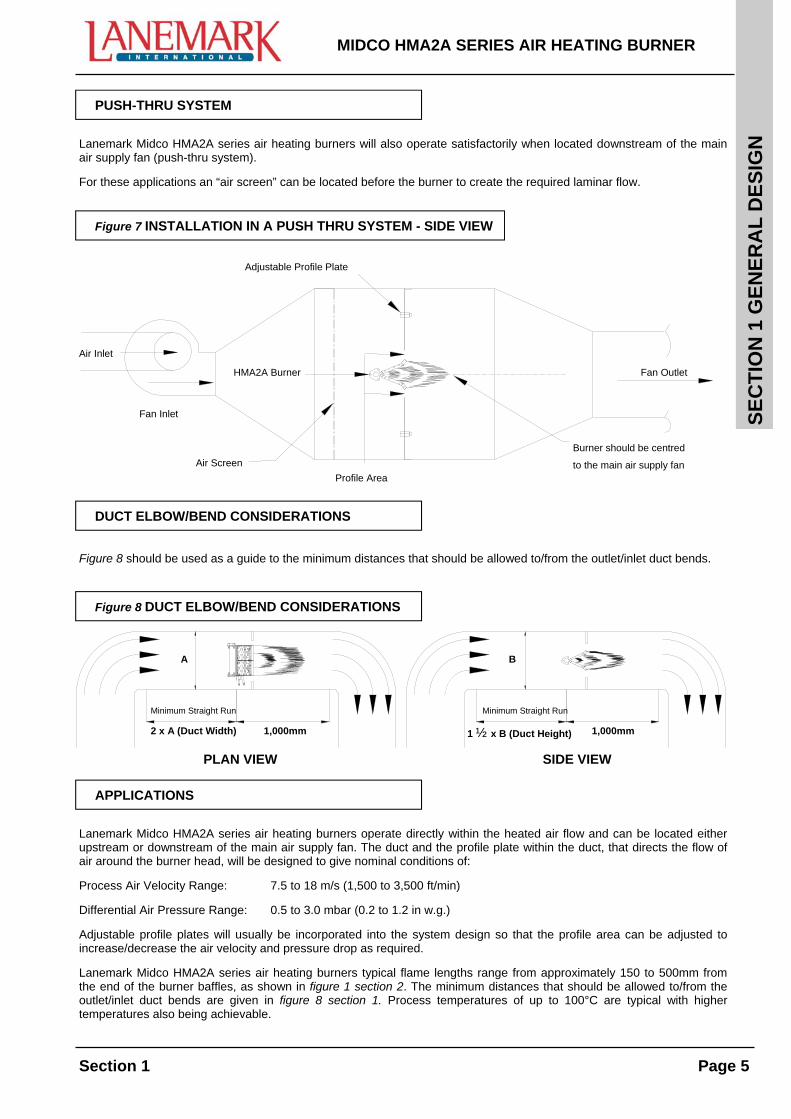
PUSH-THRU SYSTEM
Lanemark Midco HMA2A series air heating burners will also operate satisfactorily when located downstream of the main air supply fan (push-thru system).
For these applications an “air screen” can be located before the burner to create the required laminar flow.
Figure 7 INSTALLATION IN A PUSH THRU SYSTEM - SIDE VIEW
Air Inlet
Profile PlateAdjustable
Fan OutletBurnerHMA2A
Fan Outlet
Profile Area
Centre BurnerTo The Fan(if possible)Air Screen
DUCT ELBOW/BEND CONSIDERATIONS
Figure 8 should be used as a guide to the minimum distances that should be allowed to/from the outlet/inlet duct bends.
Figure 8 DUCT ELBOW/BEND CONSIDERATIONS
PLAN VIEW SIDE VIEW
APPLICATIONS
Lanemark Midco HMA2A series air heating burners operate directly within the heated air flow and can be located either upstream or downstream of the main air supply fan. The duct and the profile plate within the duct, that directs the flow of air around the burner head, will be designed to give nominal conditions of:
Process Air Velocity Range: 7.5 to 18 m/s (1,500 to 3,500 ft/min)
Differential Air Pressure Range: 0.5 to 3.0 mbar (0.2 to 1.2 in w.g.)
Adjustable profile plates will usually be incorporated into the system design so that the profile area can be adjusted to increase/decrease the air velocity and pressure drop as required.
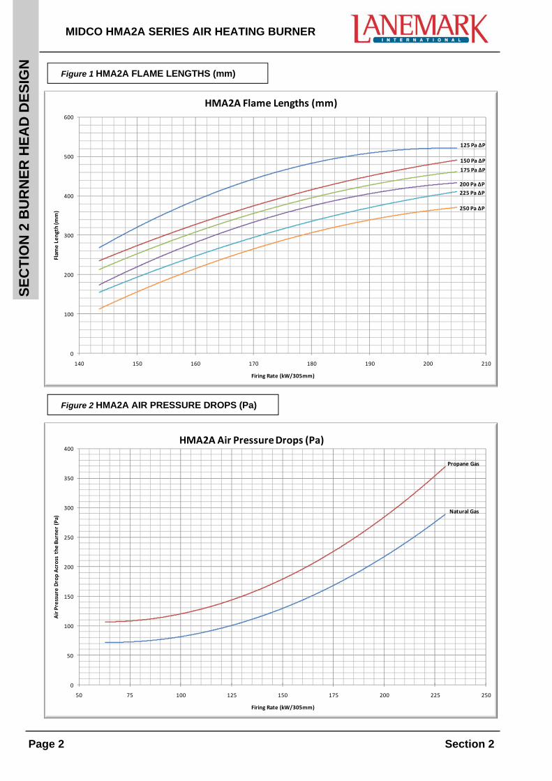
Lanemark Midco HMA2A series air heating burners typical flame lengths range from approximately 150 to 500mm from the end of the burner baffles, as shown in figure 1 section 2. The minimum distances that should be allowed to/from the outlet/inlet duct bends are given in figure 8 section 1. Process temperatures of up to 100°C are typical with higher temperatures also being achievable.
Burner should be centred
to the main air supply fan
2 x A (Duct Width)
Minimum Straight Run
1,000mm
A
1 ½ x B (Duct Height)
Minimum Straight Run
1,000mm
B
Adjustable Profile Plate
Air Inlet
Fan Inlet
Air Screen
HMA2A Burner
Profile Area
Fan Outlet
SE
CT
ION
1 G
EN
ER
AL
DE
SIG
N
MIDCO HMA2A SERIES AIR HEATING BURNER
Page 6 Section 1
GAS SUPPLY GENERAL
The outlet of the duct should have negligible resistance or a back pressure could be created within the duct, causing the differential air pressure across the burner head to be lost. The main air supply fan should have an air flow sensing system that will immediately turn the burner off, if the air flow falls below the minimum setting for safe operation.
Each Lanemark HMA2A burner must be fitted with a suitable gas valve train and burner control system conforming to individual local requirements.
In Europe the requirements of EN746 Part 2 should be observed.
Before the burner is connected to a new or existing gas supply, the Local Gas Supply Service Provider must be consulted to ensure that the gas meter and supply are of adequate size for the load required.
Lanemark’s standard gas valve train assembly (available on request) is supplied with a union to enable the quick and safe removal of the gas valve train assembly for maintenance or component replacement.
The pipework final connections should be made such that it is possible to isolate the gas supply and remove the burner for servicing without removing any gas pipework. Consideration may be given to making the final connection in an armoured flexible gas hose that complies with current standards. The gas supply pipework should be designed and installed in accordance with all relevant standards.
GAS SUPPLY
Lanemark Midco HMA2A series air heating burners are designed to operate on both natural gas and propane gas. Typical burner head pressures are:
Firing Rate Natural Gas Propane (LPG) Gas
146kW/305mm 8.8mbar 3.3mbar
161kW/305mm 10.5mbar 4.0mbar
176kW/305mm 12.5mbar 4.8mbar
190kW/305mm 14.5mbar 5.5mbar
205kW/305mm 17.0mbar 6.3mbar
SE
CT
ION
2 B
UR
NE
R H
EA
D D
ES
IGN
MIDCO HMA2A SERIES AIR HEATING BURNER
Section 2

SE
CT
ION
2 B
UR
NE
R H
EA
D D
ES
IGN
MIDCO HMA2A SERIES AIR HEATING BURNER
Section 2
SE
CT
ION
2 B
UR
NE
R H
EA
D D
ES
IGN
MIDCO HMA2A SERIES AIR HEATING BURNER
Section 2 Page 1
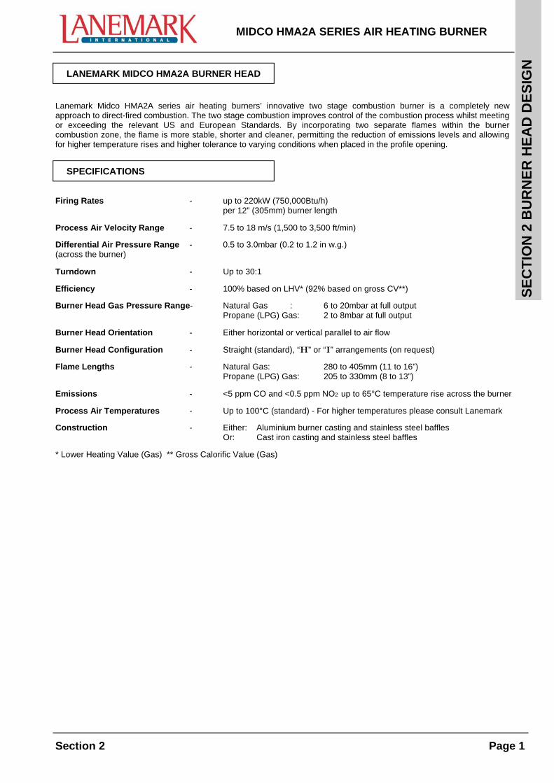
LANEMARK MIDCO HMA2A BURNER HEAD
Lanemark Midco HMA2A series air heating burners’ innovative two stage combustion burner is a completely new approach to direct-fired combustion. The two stage combustion improves control of the combustion process whilst meeting or exceeding the relevant US and European Standards. By incorporating two separate flames within the burner combustion zone, the flame is more stable, shorter and cleaner, permitting the reduction of emissions levels and allowing for higher temperature rises and higher tolerance to varying conditions when placed in the profile opening.
SPECIFICATIONS
Firing Rates - up to 220kW (750,000Btu/h) per 12” (305mm) burner length
Process Air Velocity Range - 7.5 to 18 m/s (1,500 to 3,500 ft/min)
Differential Air Pressure Range - 0.5 to 3.0mbar (0.2 to 1.2 in w.g.) (across the burner)
Turndown - Up to 30:1
Efficiency - 100% based on LHV* (92% based on gross CV**)
Burner Head Gas Pressure Range- Natural Gas : 6 to 20mbar at full output Propane (LPG) Gas: 2 to 8mbar at full output
Burner Head Orientation - Either horizontal or vertical parallel to air flow
Burner Head Configuration - Straight (standard), “H” or “I” arrangements (on request)
Flame Lengths - Natural Gas: 280 to 405mm (11 to 16”) Propane (LPG) Gas: 205 to 330mm (8 to 13”)
Emissions - <5 ppm CO and <0.5 ppm NO2 up to 65°C temperature rise across the burner
Process Air Temperatures - Up to 100°C (standard) - For higher temperatures please consult Lanemark
Construction - Either: Aluminium burner casting and stainless steel baffles Or: Cast iron casting and stainless steel baffles
* Lower Heating Value (Gas) ** Gross Calorific Value (Gas)
SE
CT
ION
2 B
UR
NE
R H
EA
D D
ES
IGN
MIDCO HMA2A SERIES AIR HEATING BURNER
Page 2 Section 2
Figure 1 HMA2A FLAME LENGTHS (mm)
Figure 2 HMA2A AIR PRESSURE DROPS (Pa)
125 Pa ΔP
150 Pa ΔP
175 Pa ΔP
200 Pa ΔP
225 Pa ΔP
250 Pa ΔP
0
100
200
300
400
500
600
140 150 160 170 180 190 200 210
Flam
e Length (m
m)
Firing Rate (kW/305mm)
HMA2A Flame Lengths (mm)
Propane Gas
Natural Gas
0
50
100
150
200
250
300
350
400
50 75 100 125 150 175 200 225 250
Air Pressure Drop Across the Burner (Pa)
Firing Rate (kW/305mm)
HMA2A Air Pressure Drops (Pa)
MIDCO HMA2A SERIES AIR HEATING BURNER
Section 2 Page 3
Figure 4 HMA2A PROFILE VELOCITIES (m/s)
SE
CT
ION
2 B
UR
NE
R H
EA
D D
ES
IGN
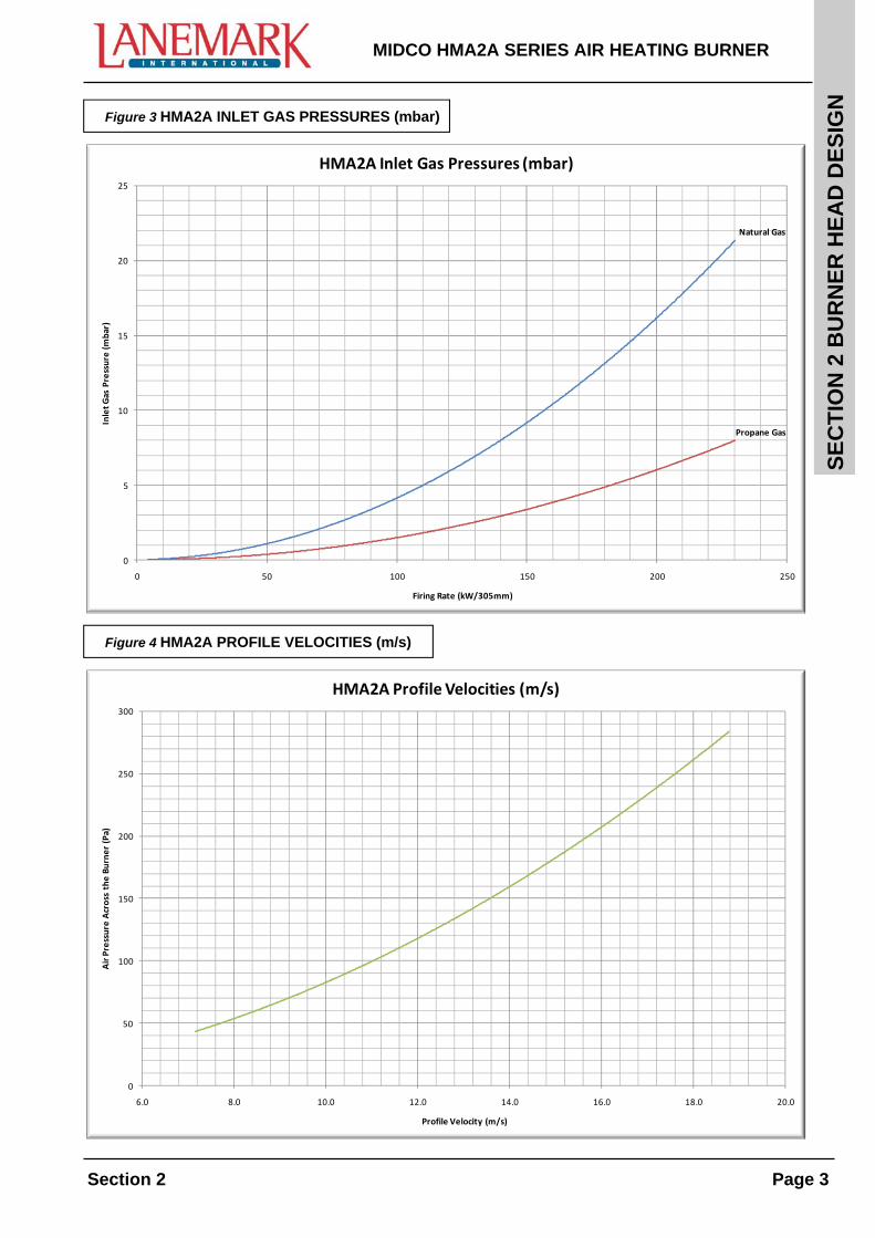
Figure 3 HMA2A INLET GAS PRESSURES (mbar)
Natural Gas
Propane Gas
0
5
10
15
20
25
0 50 100 150 200 250
Inlet Gas Pressure (mbar)
Firing Rate (kW/305mm)
HMA2A Inlet Gas Pressures (mbar)
0
50
100
150
200
250
300
6.0 8.0 10.0 12.0 14.0 16.0 18.0 20.0
Air Pressure Across the Burner (Pa)
Profile Velocity (m/s)
HMA2A Profile Velocities (m/s)
SE
CT
ION
2 B
UR
NE
R H
EA
D D
ES
IGN
MIDCO HMA2A SERIES AIR HEATING BURNER
Page 4 Section 2
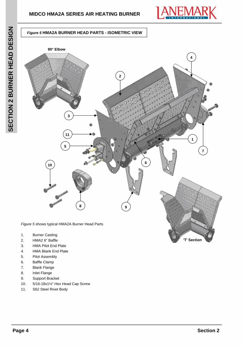
Figure 5 HMA2A BURNER HEAD PARTS - ISOMETRIC VIEW
2
3
10
4
9 8
7 5
11 1
6
Figure 5 shows typical HMA2A Burner Head Parts
1. Burner Casting
2. HMA2 6” Baffle
3. HMA Pilot End Plate
4. HMA Blank End Plate
5. Pilot Assembly
6. Baffle Clamp
7. Blank Flange
8. Inlet Flange
9. Support Bracket
10. 5/16-18x1½“ Hex Head Cap Screw
11. S62 Steel Rivet Body
'T' Section
90° Elbow
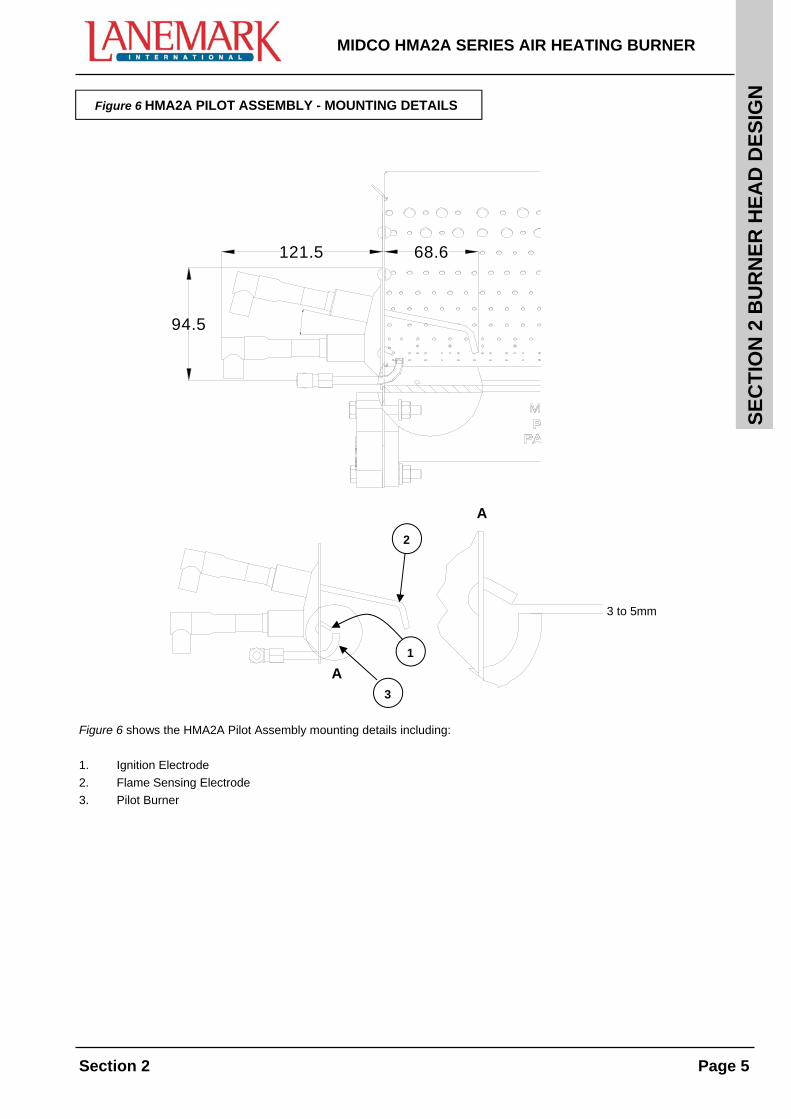
Figure 6 HMA2A PILOT ASSEMBLY - MOUNTING DETAILS
SE
CT
ION
2 B
UR
NE
R H
EA
D D
ES
IGN
MIDCO HMA2A SERIES AIR HEATING BURNER
Section 2 Page 5
A
A3 to 5mm
94.5 12°
121.5 68.6
3 to 5mm
1
2
3
A
A
Figure 6 shows the HMA2A Pilot Assembly mounting details including:
1. Ignition Electrode
2. Flame Sensing Electrode
3. Pilot Burner

SE
CT
ION
2 B
UR
NE
R H
EA
D D
ES
IGN
MIDCO HMA2A SERIES AIR HEATING BURNER
Page 6 Section 2

SE
CT
ION
3 M
AIN
TE
NA
NC
E
MIDCO HMA2A SERIES AIR HEATING BURNER
Section 3

SE
CT
ION
3 M
AIN
TE
NA
NC
E
MIDCO HMA2A SERIES AIR HEATING BURNER
Section 3
SE
CT
ION
3 M
AIN
TE
NA
NC
E
MIDCO HMA2A SERIES AIR HEATING BURNER
Section 3 Page 1
CLEANING AND MAINTENANCE
It is UK law that Lanemark Midco HMA2A series air heating burners are installed, commissioned and maintained by competent persons only, e.g. A.C.S. and GAS SAFE registered installers only. In other countries local gas regulations must be observed.
Maintenance of the burner system(s) should be conducted at regular intervals dependant on the application and the operating conditions.
Note: It is recommended that a minimum of one maintenance check is completed annually.
HMA2A SERIES BURNER HEAD
To clean and inspect the burner head assembly the following instructions should be followed:
Isolate the gas and electrical supply to the burner.
Remove the duct access hatch to enable work to be completed on the burner head assembly in its current position.
The burner head will typically have a light covering of dust on the baffles and any associated pipework. This should be removed with a lint free cloth or a soft brush and vacuumed up as necessary. The dust must be treated with care and a disposable mask and safety goggles should be worn to prevent irritation.
The burner electrodes should be checked for their serviceability and if found faulty they must be replaced.
The ignition and flame sensing electrodes should be set as shown in figure 6 section 2. A U.V. Cell may be used as an alternative method of flame sensing and if installed may require cleaning to remove any dust particles.
Upon completion of the cleaning process, all services and supplies to the burner should be reinstated.
SE
CT
ION
3 M
AIN
TE
NA
NC
E
MIDCO HMA2A SERIES AIR HEATING BURNER
Page 2 Section 3
SE
CT
ION
4 C
OM
PO
NE
NT
RE
PL
AC
EM
EN
T
MIDCO HMA2A SERIES AIR HEATING BURNER
Section 4
SE
CT
ION
4 C
OM
PO
NE
NT
RE
PL
AC
EM
EN
T
MIDCO HMA2A SERIES AIR HEATING BURNER
Section 4
SE
CT
ION
4 C
OM
PO
NE
NT
RE
PL
AC
EM
EN
T
MIDCO HMA2A SERIES AIR HEATING BURNER
Section 4 Page 1
COMPONENT REPLACEMENT
It is UK law that Lanemark Midco HMA2A series air heating burners are installed, commissioned and maintained by competent persons only, e.g. A.C.S. and GAS SAFE registered installers only. In other countries local gas regulations must be observed.
Note: Only original equipment spares supplied by Lanemark International Ltd should be fitted to the HMA2A series air heating burners to ensure their safe and correct operation.
IGNITION/ FLAME SENSING ELECTRODES
To replace the ignition electrode and/or the flame sensing electrode/U.V. Cell the following instructions should be followed:
Isolate the gas supply and electrical supply to the burner.
Remove the duct access hatch to enable work to be completed on the burner head assembly in its current position.
If a U.V. Cell is fitted, remove the unit from the fixing collar.
Individual electrodes can be replaced in situ providing there is adequate space to access the burner pilot assembly. The fixing screw located on the electrode fixing collar will need to be loosened so that the required electrode can be withdrawn from its position. The complete pilot assembly can also be removed if required. The position of the electrodes should be set as shown in figure 6 Section 2.
The performance of the electrode(s) and U.V. Cell (if fitted) should be checked by starting the burner and checking for satisfactory ignition and flame detection signal.
HMA2A BURNER HEAD ASSEMBLY
To replace the burner head assembly the following instructions should be followed:
Isolate the gas supply and electrical supply to the burner.
The burner head assembly can be extracted from the duct once the associated gas valve train has been suitably removed (this can usually be done by breaking the union on the gas valve train assembly). It should now be possible to remove the burner head assembly.
If the burner is to be left unattended then the incoming gas supply must be capped off, it must not be left isolated at the isolating gas ball valve alone.
The burner head assembly can now be removed from any associated support pipework and the replacement can now be installed.
The position of the electrodes should be checked and set as shown in figure 6 Section 2.
The burner head assembly can now be re-installed into the duct with the gas connection being re-instated and checked for its integrity.
The burner settings must be checked, set and recorded accordingly.
MIDCO HMA2A SERIES AIR HEATING BURNER
Extra copies of this manual are available at £25.00 each + V.A.T. Please quote the Job Number on the front cover of this
burner manual. (Price correct at time of printing).