Embed Size (px)
Citation preview
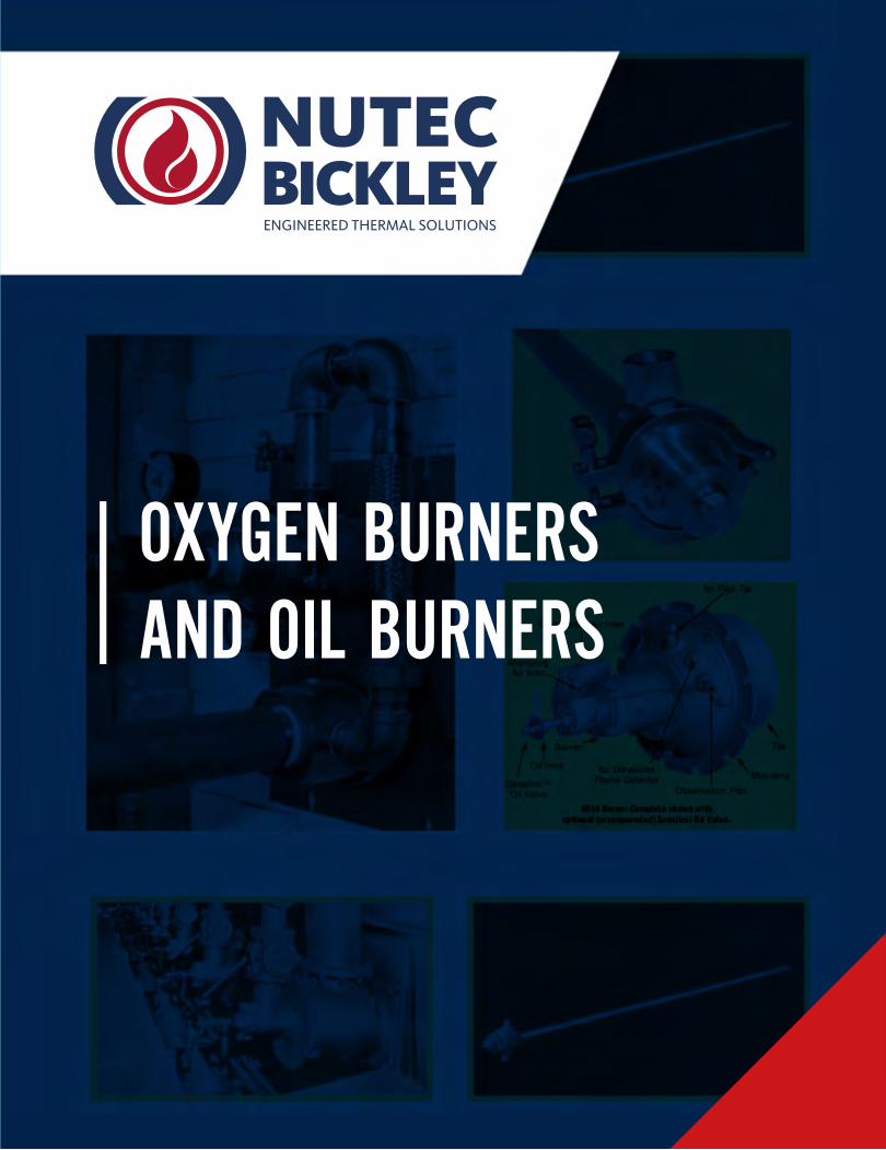
OXYGEN BURNERS AND OIL BURNERS
North American Oxy-Fuel Jet Burners Bulletin 5010-J
The 5010-J burner is designed for glass and aluminum melter requirements of no water cooling and low oxy-gen supply pressures. Benefi ts of oxygen/fuel fi ring are faster melting, low NOx emissions, and smaller volume of combustion gas which permits a smaller bag house when required. There are two burner sizes: the -J1 has four diff erent capacity nozzles available and the J3 size has 7 nozzles.
OPERATION
A high velocity luminous fl ame is produced by this con-centric pipe burner. Fuel fl ows through the center passage while low velocity oxygen fl ows through the outer annulus. The fuel tube can be easily removed from the back of the burner for inspection. An oil model is available.
The 5010-J burner dœ s not have a standard pilot or spark electrode. The burner can be ignited with a torch or in-serted when the furnace temperature exceeds 1400 F.
FLAME SUPERVISION
The burner has a rear connection that can accept a UV scanner. The connection is not available with oil models. Contact North American for application information. If a fl ame supervision system is not used, the burner should only be operated aft er the chamber temperature is above 1400 F.
FUEL/OXYGEN REQUIREMENTS
Burner models operate on natural gas (5010-J) or oil (5011-J). Contact North American for oil model details. Required pressures for oxygen and gas are listed in the data table on page two. Because required oxygen pressure is so low, optional balancing orifi ces are requried to evenly distribute oxygen to all burners in a zone. Use of the orifi ce will raise required oxygen pressure to approximately one psig.
MOUNTING
The burner is available with either a fi xed welded fl ange, or an adjustable set-screw held fl ange, for holding pack-ing between the burner and furnace wall. The welded fl ange location should be specifi ed at time of order. An optional mounting adapter allows angled or straight instal-lation. Specify angle when ordering.
COOLING REQUIREMENTS
The burner is cooled by oxygen and fuel fl ows during operation. However, if the burner is going to be exposed to a hot furnace while not in operation, it must be pulled from the furnace. An air cooled mounting is available for special high temperature applications. Consult North American for details.
Combustion
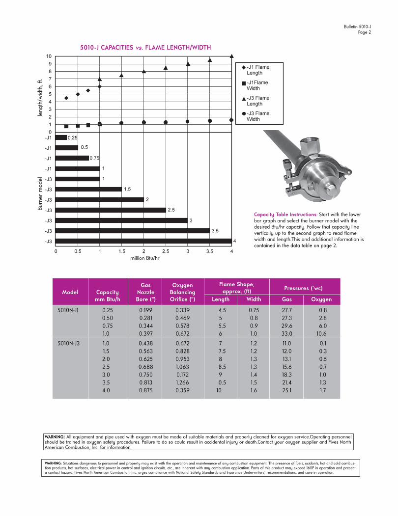
Gas Oxygen Model Capacity Nozzle Balancing
mm Btu/h Bore (") Orifi ce (") Length Width Gas Oxygen
5010N-J1 0.25 0.199 0.339 4.5 0.75 27.7 0.80.50 0.281 0.469 5 0.8 27.3 2.80.75 0.344 0.578 5.5 0.9 29.6 6.01.0 0.397 0.672 6 1.0 33.0 10.6
5010N-J3 1.0 0.438 0.672 7 1.2 11.0 0.11.5 0.563 0.828 7.5 1.2 12.0 0.32.0 0.625 0.953 8 1.3 13.1 0.52.5 0.688 1.063 8.5 1.3 15.6 0.73.0 0.750 0.172 9 1.4 18.3 1.03.5 0.813 1.266 0.5 1.5 21.4 1.34.0 0.875 0.359 10 1.6 25.1 1.7
Pressures ('wc)Flame Shape,approx. (ft )
WARNING: All equipment and pipe used with oxygen must be made of suitable materials and properly cleaned for oxygen service.Operating personnelshould be trained in oxygen safety procedures. Failure to do so could result in accidental injury or death.Contact your oxygen supplier and Fives North American Combustion, Inc. for information.
Bulletin 5010-JPage 2
Capacity Table Instructions: Start with the lower bar graph and select the burner model with the desired Btu/hr capacity. Follow that capacity line vertically up to the second graph to read fl ame width and length.This and additional information is contained in the data table on page 2.
Burn
er m
odel
le
ngth
/wid
th, ft
.
million Btu/hr
5010-J CAPACITIES vs. FLAME LENGTH/WIDTH
WARNING: Situations dangerous to personnel and property may exist with the operation and maintenance of any combustion equipment. The presence of fuels, oxidants, hot and cold combus-tion products, hot surfaces, electrical power in control and ignition circuits, etc., are inherent with any combustion application. Parts of this product may exceed 160F in operation and present a contact hazard. Fives North American Combustion, Inc. urges compliance with National Safety Standards and Insurance Underwriters' recommendations, and care in operation.
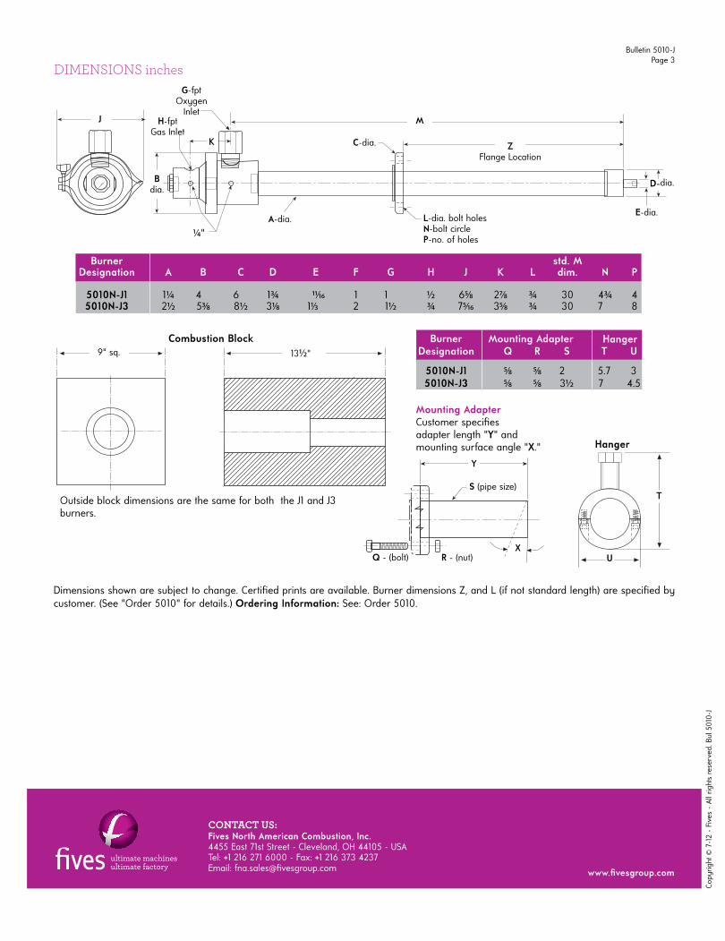
DIMENSIONS inches
Burner std. M Designation A B C D E F G H J K L dim. N P
5010N-J1 1¼ 4 6 1¾ 11⁄16 1 1 ½ 65⁄8 27⁄8 ¾ 30 4¾ 4 5010N-J3 2½ 53⁄8 8½ 31⁄8 11⁄3 2 1½ ¾ 75⁄16 35⁄8 ¾ 30 7 8
Burner Designation Q R S T U
5010N-J1 5⁄8 5⁄8 2 5.7 3 5010N-J3 5⁄8 5⁄8 3½ 7 4.5
Outside block dimensions are the same for both the J1 and J3 burners.
Dimensions shown are subject to change. Certifi ed prints are available. Burner dimensions Z, and L (if not standard length) are specifi ed by customer. (See "Order 5010" for details.) Ordering Information: See: Order 5010.
Mounting Adapter
Mounting AdapterCustomer specifi es adapter length "Y" and mounting surface angle "X."
X
Hanger
S (pipe size)
R - (nut)Q - (bolt)
Combustion Block
E-dia.
H-fptGas Inlet
A-dia. L-dia. bolt holesN-bolt circleP-no. of holes
C-dia.
G-fptOxygen
Inlet
¼ "
Y
U
T
9" sq. 13½ "
J
Bdia.
K
M
ZFlange Location
D-dia.
Bulletin 5010-JPage 3
Copy
right
© 7
-12
- Fi
ves
- Al
l rig
hts
rese
rved
. Bul
501
0-J
CONTACT US:Fives North American Combustion, Inc. 4455 East 71st Street - Cleveland, OH 44105 - USA Tel: +1 216 271 6000 - Fax: +1 216 373 4237Email: fna.sales@fi vesgroup.com www.fi vesgroup.com
Hanger
— Superior luminous fl ame heat transfer
— Exceptionally Low NOx
— Low Oxygen Pressure Requirement
— Simple Installation
— Simple low maintenance Operation
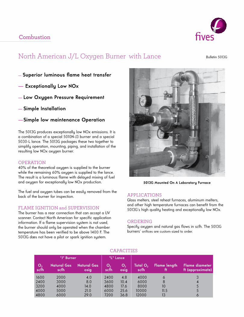
5013G Mounted On A Laboratory Furnace
"J" Burner "L" Lance O2 Natural Gas Natural Gas O2 O2 Total O2 Flame length Flame diameter scfh scfh osig scfh osig scfh ft ft (approximate)
1600 2000 4.0 2400 4.8 4000 6 3 2400 3000 8.0 3600 10.4 6000 8 4 3200 4000 14.0 4800 17.6 8000 10 5 4000 5000 21.0 6000 25.6 10000 11.5 5 4800 6000 29.0 7200 36.8 12000 13 6
The 5013G produces exceptionally low NOx emissions. It is a combination of a special 5010N-J3 burner and a special 5030-L lance. The 5013G packages these two together to simplify operation, mounting, piping, and installation of the resulting low NOx oxygen burner.
OPERATION40% of the theoretical oxygen is supplied to the burner while the remaining 60% oxygen is supplied to the lance. The result is a luminous fl ame with delayed mixing of fuel and oxygen for exceptionally low NOx production.
The fuel and oxygen tubes can be easily removed from the back of the burner for inspection.
FLAME IGNITION and SUPERVISIONThe burner has a rear connection that can accept a UV scanner. Contact North American for specifi c application information. If a fl ame supervision system is not used, the burner should only be operated when the chamber temperature has been verifi ed to be above 1400 F. The 5013G dœ s not have a pilot or spark ignition system.
APPLICATIONSGlass melters, steel reheat furnaces, aluminum melters, and other high temperature furnaces can benefi t from the 5013G's high quality heating and exceptionally low NOx.
ORDERINGSpecify oxygen and natural gas fl ows in scfh. The 5013G burners' orifi ces are custom-sized to order.
North American J/L Oxygen Burner with Lance Bulletin 5013G
CAPACITIES
Combustion
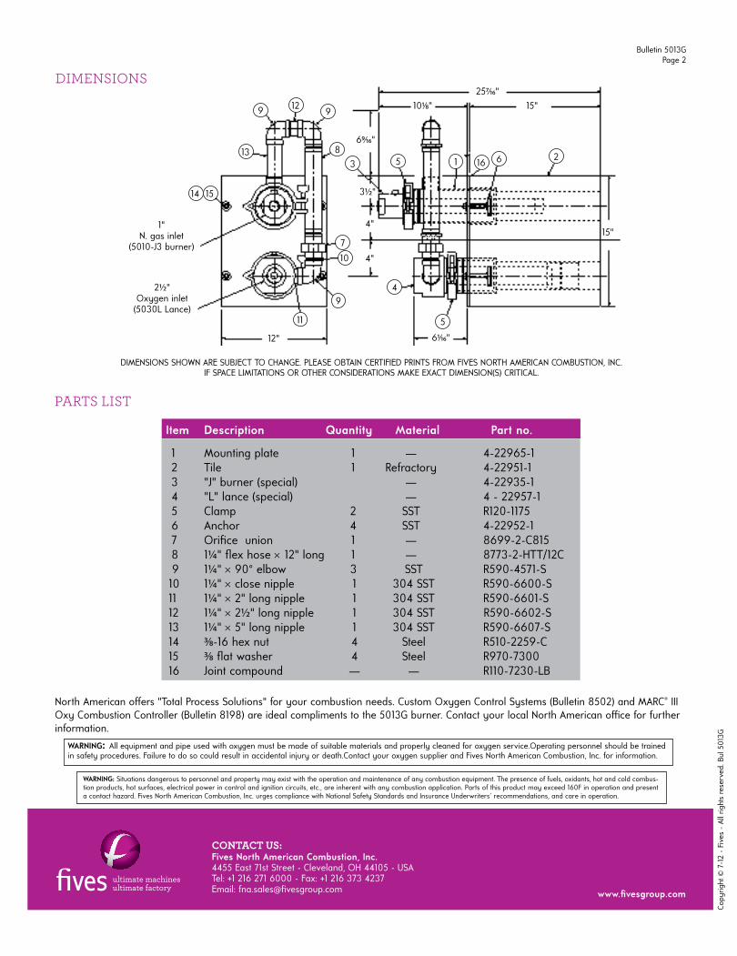
DIMENSIONS
Item Description Quantity Material Part no.
1 Mounting plate 1 — 4-22965-1 2 Tile 1 Refractory 4-22951-1 3 "J" burner (special) — 4-22935-1 4 "L" lance (special) — 4 - 22957-1 5 Clamp 2 SST R120-1175 6 Anchor 4 SST 4-22952-1 7 Orifi ce union 1 — 8699-2-C815 8 1¼ " fl ex hose 12" long 1 — 8773-2-HTT/12C 9 1¼ " 90° elbow 3 SST R590-4571-S 10 1¼ " close nipple 1 304 SST R590-6600-S 11 1¼ " 2" long nipple 1 304 SST R590-6601-S 12 1¼ " 2½ " long nipple 1 304 SST R590-6602-S 13 1¼ " 5" long nipple 1 304 SST R590-6607-S 14 3⁄8-16 hex nut 4 Steel R510-2259-C 15 3⁄8 fl at washer 4 Steel R970-7300 16 Joint compound — — R110-7230-LB
PARTS LIST
DIMENSIONS SHOWN ARE SUBJECT TO CHANGE. PLEASE OBTAIN CERTIFIED PRINTS FROM FIVES NORTH AMERICAN COMBUSTION, INC.IF SPACE LIMITATIONS OR OTHER CONSIDERATIONS MAKE EXACT DIMENSION(S) CRITICAL.
13
14
9
15
129
8
7
10
9
11
3 5 1 16 6 2
5
4
1"N. gas inlet
(5010-J3 burner)
2½ "Oxygen inlet
(5030L Lance)
12"
69⁄16"
3½ "
4"
4"
61⁄16"
15"
101⁄8" 15"257⁄16"
North American off ers "Total Process Solutions" for your combustion needs. Custom Oxygen Control Systems (Bulletin 8502) and MARC® III Oxy Combustion Controller (Bulletin 8198) are ideal compliments to the 5013G burner. Contact your local North American offi ce for further information.
WARNING: All equipment and pipe used with oxygen must be made of suitable materials and properly cleaned for oxygen service.Operating personnel should be trainedin safety procedures. Failure to do so could result in accidental injury or death.Contact your oxygen supplier and Fives North American Combustion, Inc. for information.
Bulletin 5013GPage 2
Copy
right
© 7
-12
- Fi
ves
- Al
l rig
hts
rese
rved
. Bul
501
3G
CONTACT US:Fives North American Combustion, Inc. 4455 East 71st Street - Cleveland, OH 44105 - USA Tel: +1 216 271 6000 - Fax: +1 216 373 4237Email: fna.sales@fi vesgroup.com www.fi vesgroup.com
WARNING: Situations dangerous to personnel and property may exist with the operation and maintenance of any combustion equipment. The presence of fuels, oxidants, hot and cold combus-tion products, hot surfaces, electrical power in control and ignition circuits, etc., are inherent with any combustion application. Parts of this product may exceed 160F in operation and present a contact hazard. Fives North American Combustion, Inc. urges compliance with National Safety Standards and Insurance Underwriters' recommendations, and care in operation.
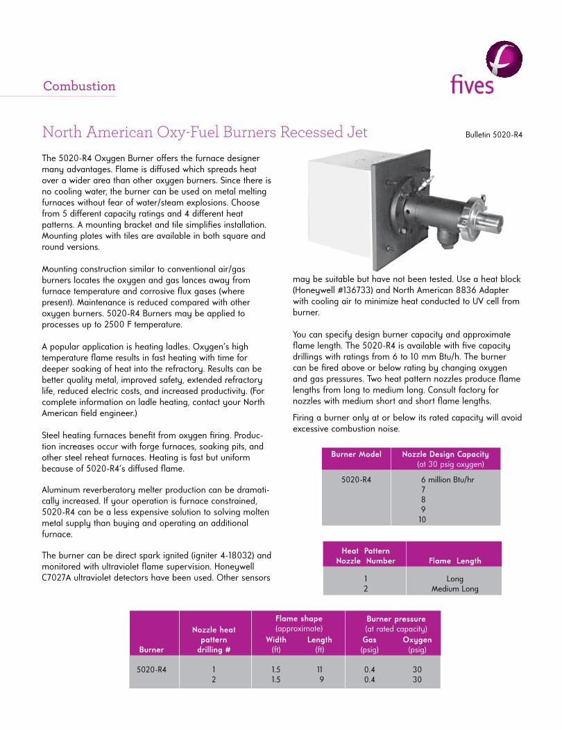
Heat Pattern Nozzle Number Flame Length 1 Long 2 Medium Long
Nozzle heat pattern Width Length Gas Oxygen Burner drilling # (ft ) (ft ) (psig) (psig) 5020-R4 1 1.5 11 0.4 30 2 1.5 9 0.4 30
North American Oxy-Fuel Burners Recessed Jet Bulletin 5020-R4
Flame shape(approximate)
Burner pressure(at rated capacity)
The 5020-R4 Oxygen Burner off ers the furnace designer many advantages. Flame is diff used which spreads heat over a wider area than other oxygen burners. Since there is no cooling water, the burner can be used on metal melting furnaces without fear of water/steam explosions. Choose from 5 diff erent capacity ratings and 4 diff erent heat patterns. A mounting bracket and tile simplifi es installation. Mounting plates with tiles are available in both square and round versions.
Mounting construction similar to conventional air/gas burners locates the oxygen and gas lances away from furnace temperature and corrosive fl ux gases (where present). Maintenance is reduced compared with other oxygen burners. 5020-R4 Burners may be applied to processes up to 2500 F temperature.
A popular application is heating ladles. Oxygen’s high temperature fl ame results in fast heating with time for deeper soaking of heat into the refractory. Results can be better quality metal, improved safety, extended refractory life, reduced electric costs, and increased productivity. (For complete information on ladle heating, contact your North American fi eld engineer.)
Steel heating furnaces benefi t from oxygen fi ring. Produc-tion increases occur with forge furnaces, soaking pits, and other steel reheat furnaces. Heating is fast but uniform because of 5020-R4’s diff used fl ame.
Aluminum reverberatory melter production can be dramati-cally increased. If your operation is furnace constrained, 5020-R4 can be a less expensive solution to solving molten metal supply than buying and operating an additional furnace.
The burner can be direct spark ignited (igniter 4-18032) and monitored with ultraviolet fl ame supervision. Honeywell C7027A ultraviolet detectors have been used. Other sensors
may be suitable but have not been tested. Use a heat block (Honeywell #136733) and North American 8836 Adapter with cooling air to minimize heat conducted to UV cell from burner.
You can specify design burner capacity and approximate fl ame length. The 5020-R4 is available with fi ve capacity drillings with ratings from 6 to 10 mm Btu/h. The burner can be fi red above or below rating by changing oxygen and gas pressures. Two heat pattern nozzles produce fl ame lengths from long to medium long. Consult factory for nozzles with medium short and short fl ame lengths.
Firing a burner only at or below its rated capacity will avoid excessive combustion noise.
Burner Model Nozzle Design Capacity (at 30 psig oxygen) 5020-R4 6 million Btu/hr 7 million Btu/hr 8 million Btu/hr 9 million Btu/hr 10million Btu/hr
Combustion
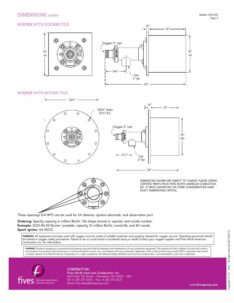
DIMENSIONS inches
WARNING: All equipment and pipe used with oxygen must be made of suitable materials and properly cleaned for oxygen service. Operating personnel should be trained in oxygen safety procedures. Failure to do so could result in accidental injury or death.Contact your oxygen supplier and Fives North American Combustion, Inc. for information.
Ordering: Specify capacity in million Btu/hr, Tile shape (round or square), and nozzle number.Example: 5020-R4-XX Burner complete, capacity 10 million Btu/hr, round tile, and #2 nozzle.Spark Igniter: A4-18032
DIMENSIONS SHOWN ARE SUBJECT TO CHANGE. PLEASE OBTAIN CERTIFIED PRINTS FROM FIVES NORTH AMERICAN COMBUSTION, INC. IF SPACE LIMITATIONS OR OTHER CONSIDERATIONS MAKE EXACT DIMENSION(S) CRITICAL.
Three openings (1/4 NPT) can be used for UV detector, ignition electrode, and observation port.
BURNER WITH SQUARE TILE
BURNER WITH ROUND TILE
Oxygen 2" mpt
Gas2” fpt
12"sq
6¾ "
12"
26"
22½ "
Oxygen 2" mpt
5⁄8"
Gas2" fpt
5⁄8"
63/4"
26"
12"
14”sq
(12)¾ " holes20½ " B.C.
16"dia.
Bulletin 5020-R4Page 2
Copy
right
© 7
-12
- Fi
ves
- Al
l rig
hts
rese
rved
. Bul
502
0-r4
CONTACT US:Fives North American Combustion, Inc. 4455 East 71st Street - Cleveland, OH 44105 - USA Tel: +1 216 271 6000 - Fax: +1 216 373 4237Email: fna.sales@fi vesgroup.com www.fi vesgroup.com
WARNING: Situations dangerous to personnel and property may exist with the operation and maintenance of any combustion equipment. The presence of fuels, oxidants, hot and cold combus-tion products, hot surfaces, electrical power in control and ignition circuits, etc., are inherent with any combustion application. Parts of this product may exceed 160F in operation and present a contact hazard. Fives North American Combustion, Inc. urges compliance with National Safety Standards and Insurance Underwriters' recommendations, and care in operation.
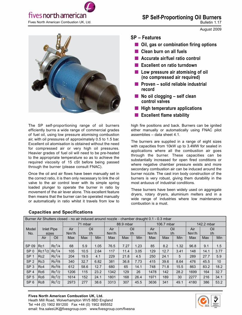
SP Self-Proportioning Oil BurnersBulletin 1.17
August 2009
The SP self-proportioning range of oil burnersefficiently burns a wide range of commercial gradesof fuel oil, using low pressure atomising combustionair, with oil pressures of approximately 0.5 to 1.5 bar.Excellent oil atomisation is obtained without the needfor compressed air or very high oil pressures.Heavier grades of fuel oil will need to be pre-heatedto the appropriate temperature so as to achieve therequired viscosity of 15 cSt before being passedthrough the burner (please consult FNAC).
Once the oil and air flows have been manually set inthe correct ratio, it is then only necessary to link the oilvalve to the air control lever with its simple springloaded plunger to operate the burner in ratio bymovement of the air lever alone. This excellent featurethen means that the burner can be operated manuallyor automatically in ratio whilst it travels from low to
SP – Features� Oil, gas or combination firing options� Clean burn on all fuels� Accurate air/fuel ratio control� Excellent on ratio turndown� Low pressure air atomising of oil
(no compressed air required)� Proven – solid reliable industrial
record� No oil clogging – self clean
control valves� High temperature applications� Excellent flame stability
high fire positions and back. Burners can be ignitedeither manually or automatically using FNAC pilotassemblies – data sheet 4.1.
The burners are supplied in a range of eight sizeswith capacities from 10kW up to 3.4MW for sealed inapplications where all the combustion air goesthrough the burner. These capacities can besubstantially increased for open fired conditions orwhere negative chamber pressure exists and moresecondary combustion air can be induced around theburner nozzle. The cast iron body construction of theburners is very robust, giving them durability in themost arduous of industrial conditions.
These burners have been widely used on aggregatedryers, rotary dryers, aluminium melters and in awide range of industries where low maintenancecombustion is a must.
SP 09 Rc1 Rc1/4 68 5.9 1.05 76.5 7.27 1.23 85 8.2 1.32 96.8 9.1 1.5
SP 0 Rc11/2 Rc1/4 105 10.5 2.64 117 11.4 3.05 129 12.7 3.41 148 14.1 3.77
SP 1 Rc2 Rc1/4 204 19.5 4.1 229 21.8 4.5 250 24.1 5 289 27.7 5.9
SP 2 Rc3 Rc3/8 340 32.7 6.82 381 36.8 7.73 415 39.6 8.64 476 45.5 10
SP 3 Rc4 Rc3/8 612 58.6 12.7 680 65 14.1 748 71.8 15.5 863 83.2 18.2
SP 4 Rc6 Rc1/2 1206 115 23.2 1342 129 26 1478 142 28.2 1699 164 32.7
SP 5 Rc6 Rc1/2 1614 152 24.1 1801 168 26.4 1971 189 30 2277 216 34.1
SP 6 Rc8 Rc1/2 2973 277 38.6 3313 307 45.5 3636 341 49.1 4180 386 53.2
Capacities and Specifications
ModelNo.
Inlet Pipesizes
Air Oil
Burner Air Shutters closed - no air induced around nozzle - chamber draught 0.1 - 0.3 mbar
AirNm3/hMax
71 mbarOill/h
Max Min
AirNm3/hMax
88.9 mbarOill/h
Max Min
106.7 mbarAir
Nm3/hMax
142.2 mbarOill/h
Max Min
AirNm3/hMax
Oill/h
Max Min
Fives North American Combustion UK, Ltd.
Fives North American Combustion UK, Ltd.Heath Mill Road, Wolverhampton WV5 8BD EnglandTel +44 (0) 1902 891200 Fax +44 (0) 1902 895552email: [email protected] www.fivesgroup.com/fivesna
Page 2Bulletin 1.17
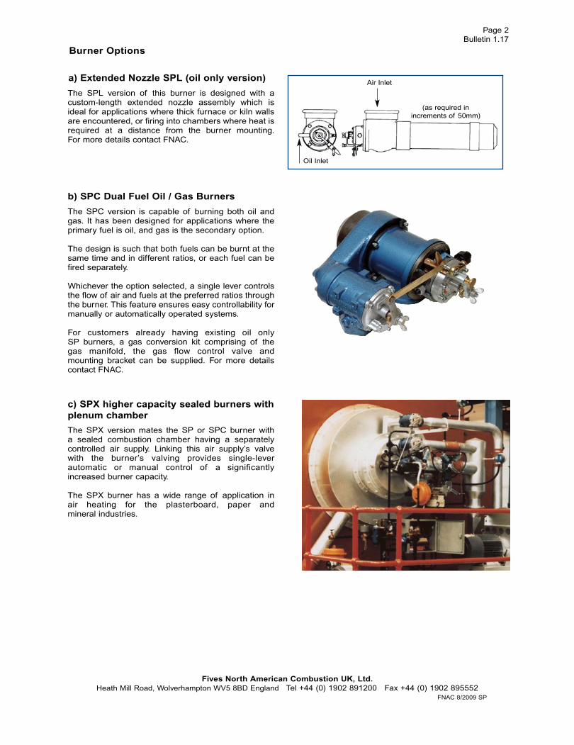
a) Extended Nozzle SPL (oil only version)
The SPL version of this burner is designed with acustom-length extended nozzle assembly which isideal for applications where thick furnace or kiln wallsare encountered, or firing into chambers where heat isrequired at a distance from the burner mounting.For more details contact FNAC.
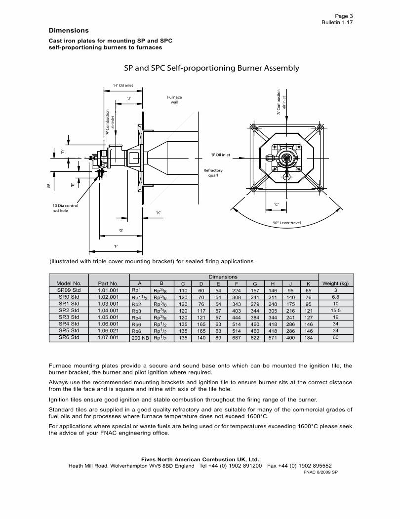
b) SPC Dual Fuel Oil / Gas Burners
The SPC version is capable of burning both oil andgas. It has been designed for applications where theprimary fuel is oil, and gas is the secondary option.
The design is such that both fuels can be burnt at thesame time and in different ratios, or each fuel can befired separately.
Whichever the option selected, a single lever controlsthe flow of air and fuels at the preferred ratios throughthe burner. This feature ensures easy controllability formanually or automatically operated systems.
For customers already having existing oil onlySP burners, a gas conversion kit comprising of thegas manifold, the gas flow control valve andmounting bracket can be supplied. For more detailscontact FNAC.
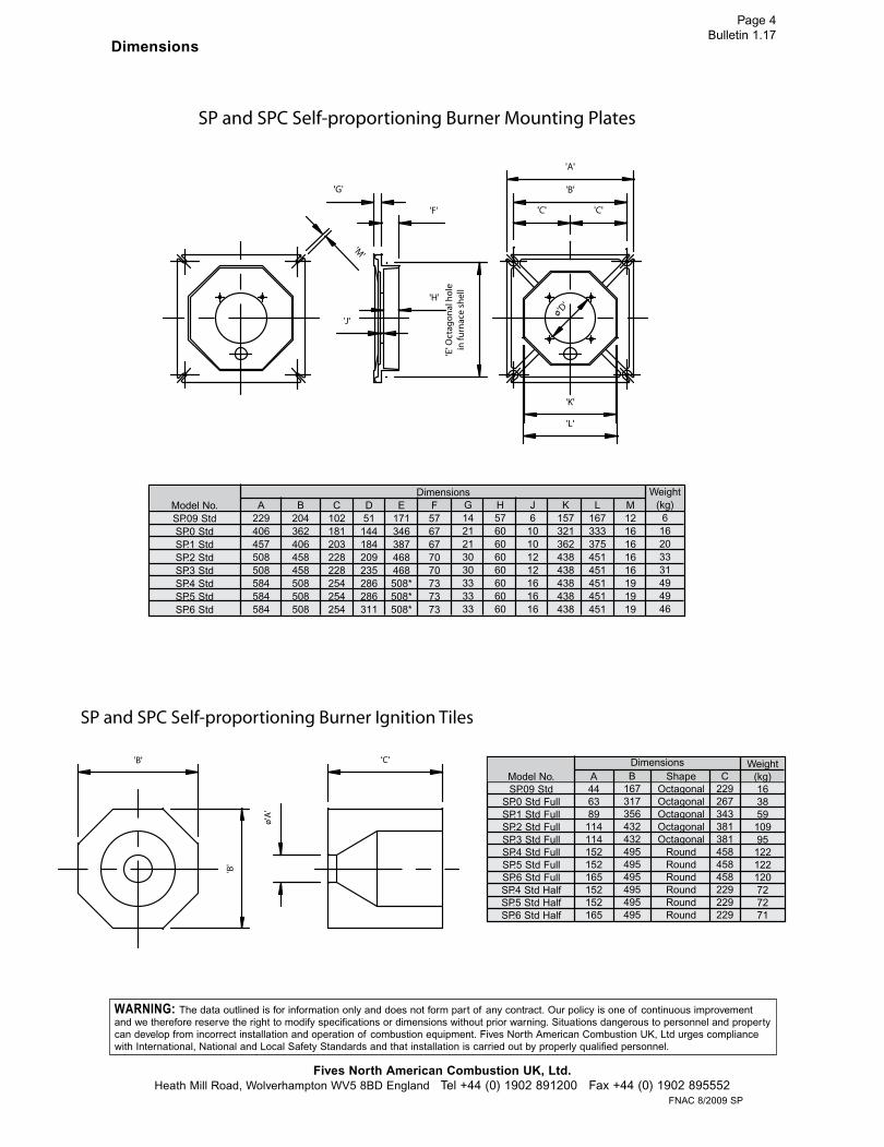
c) SPX higher capacity sealed burners withplenum chamber
The SPX version mates the SP or SPC burner witha sealed combustion chamber having a separatelycontrolled air supply. Linking this air supply’s valvewith the burner’s valving provides single-leverautomatic or manual control of a significantlyincreased burner capacity.
The SPX burner has a wide range of application inair heating for the plasterboard, paper andmineral industries.
Air Inlet
Oil Inlet
(as required inincrements of 50mm)
Burner Options
Fives North American Combustion UK, Ltd.Heath Mill Road, Wolverhampton WV5 8BD England Tel +44 (0) 1902 891200 Fax +44 (0) 1902 895552
FNAC 8/2009 SP
Page 3Bulletin 1.17
Dimensions
Cast iron plates for mounting SP and SPCself-proportioning burners to furnaces
Furnace mounting plates provide a secure and sound base onto which can be mounted the ignition tile, theburner bracket, the burner and pilot ignition where required.
Always use the recommended mounting brackets and ignition tile to ensure burner sits at the correct distancefrom the tile face and is square and inline with axis of the tile hole.
Ignition tiles ensure good ignition and stable combustion throughout the firing range of the burner.
Standard tiles are supplied in a good quality refractory and are suitable for many of the commercial grades offuel oils and for processes where furnace temperature does not exceed 1600°C.
For applications where special or waste fuels are being used or for temperatures exceeding 1600°C please seekthe advice of your FNAC engineering office.
(illustrated with triple cover mounting bracket) for sealed firing applications
DimensionsModel No.SP.09 StdSP.0 StdSP.1 StdSP.2 StdSP.3 StdSP.4 StdSP.5 StdSP.6 Std
Part No.1.01.0011.02.0011.03.0011.04.0011.05.0011.06.0011.06.0211.07.001
ARp1
Rp11/2Rp2Rp3Rp4Rp6Rp6200 NB
C110120120120120135135135
D607076117121165165140
E5454545757636389
F224308343403444514514687
B
Rp3/8Rp3/8Rp3/8Rp3/8Rp3/8Rp1/2Rp1/2Rp1/2
G157241279344384460460622
H146211248305344418418571
J95140175216241286286400
K657695
121127146146184
Weight (kg)3
6.810
15.519343460
Fives North American Combustion UK, Ltd.Heath Mill Road, Wolverhampton WV5 8BD England Tel +44 (0) 1902 891200 Fax +44 (0) 1902 895552
FNAC 8/2009 SP
Page 4Bulletin 1.17
Dimensions
DimensionsG1421213030333333
H5760606060606060
J6
10101212161616
K157321362438438438438438
L167333375451451451451451
M1216161616191919
Weight(kg)
616203331494946
A229406457508508584584584
B204362406458458508508508
C102181203228228254254254
D51144184209235286286311
E171346387468468508*508*508*
F5767677070737373
Model No.SP.09 StdSP.0 StdSP.1 StdSP.2 StdSP.3 StdSP.4 StdSP.5 StdSP.6 Std
DimensionsB
167317356432432495495495495495495
C229267343381381458458458229229229
Weight(kg)16385910995122122120727271
ShapeOctagonalOctagonalOctagonalOctagonalOctagonal
RoundRoundRoundRoundRoundRound
Model No.SP.09 Std
SP.0 Std FullSP.1 Std FullSP.2 Std FullSP.3 Std FullSP.4 Std FullSP.5 Std FullSP.6 Std FullSP.4 Std HalfSP.5 Std HalfSP.6 Std Half
A446389
114114152152165152152165
Fives North American Combustion UK, Ltd.Heath Mill Road, Wolverhampton WV5 8BD England Tel +44 (0) 1902 891200 Fax +44 (0) 1902 895552
FNAC 8/2009 SP
WARNING: The data outlined is for information only and does not form part of any contract. Our policy is one of continuous improvementand we therefore reserve the right to modify specifications or dimensions without prior warning. Situations dangerous to personnel and propertycan develop from incorrect installation and operation of combustion equipment. Fives North American Combustion UK, Ltd urges compliancewith International, National and Local Safety Standards and that installation is carried out by properly qualified personnel.
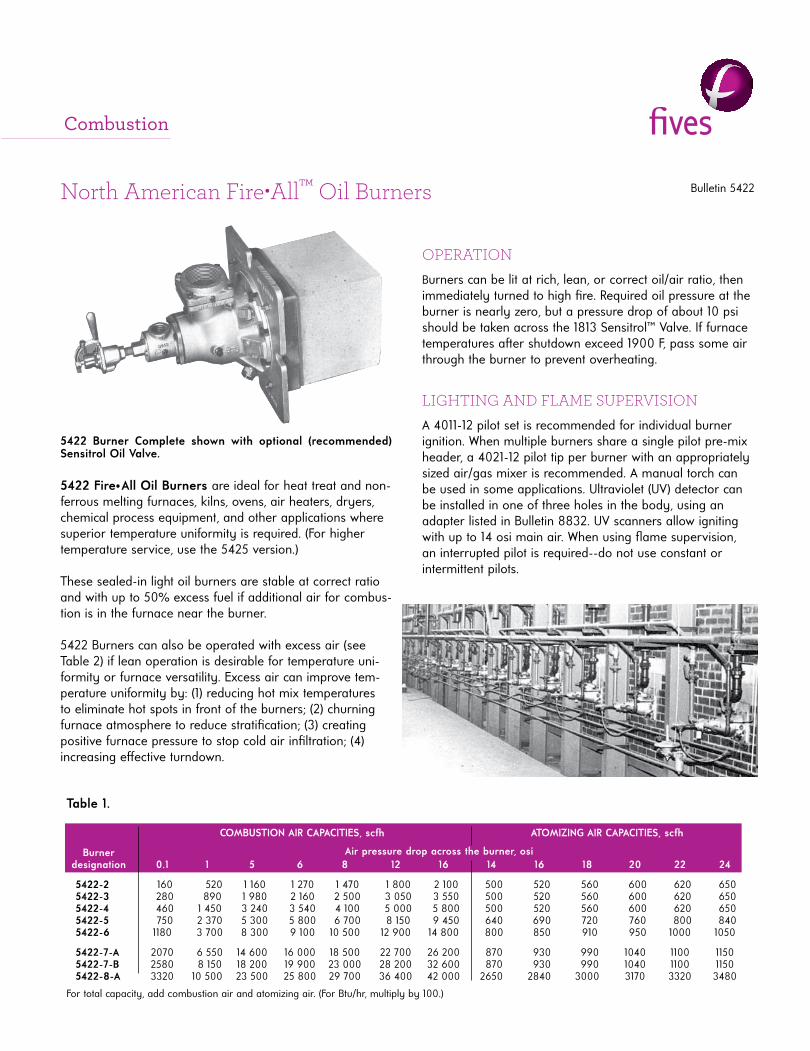
Bulletin 5422North American Fire•All™ Oil Burners
5422 Fire•All Oil Burners are ideal for heat treat and non-ferrous melting furnaces, kilns, ovens, air heaters, dryers, chemical process equipment, and other applications where superior temperature uniformity is required. (For higher temperature service, use the 5425 version.)
These sealed-in light oil burners are stable at correct ratio and with up to 50% excess fuel if additional air for combus-tion is in the furnace near the burner.
5422 Burners can also be operated with excess air (see Table 2) if lean operation is desirable for temperature uni-formity or furnace versatility. Excess air can improve tem-perature uniformity by: (1) reducing hot mix temperatures to eliminate hot spots in front of the burners; (2) churning furnace atmosphere to reduce stratifi cation; (3) creating positive furnace pressure to stop cold air infi ltration; (4) increasing eff ective turndown.
5422 Burner Complete shown with optional (recommended) Sensitrol Oil Valve.
LIGHTING AND FLAME SUPERVISIONA 4011-12 pilot set is recommended for individual burner ignition. When multiple burners share a single pilot pre-mix header, a 4021-12 pilot tip per burner with an appropriately sized air/gas mixer is recommended. A manual torch can be used in some applications. Ultraviolet (UV) detector can be installed in one of three holes in the body, using an adapter listed in Bulletin 8832. UV scanners allow igniting with up to 14 osi main air. When using fl ame supervision, an interrupted pilot is required--do not use constant or intermittent pilots.
Table 1.
COMBUSTION AIR CAPACITIES, scfh
Burner designation 0.1 1 5 6 8 12 16 14 16 18 20 22 24
5422-2 160 520 1 160 1 270 1 470 1 800 2 100 500 520 560 600 620 650 5422-3 280 890 1 980 2 160 2 500 3 050 3 550 500 520 560 600 620 650 5422-4 460 1 450 3 240 3 540 4 100 5 000 5 800 500 520 560 600 620 650 5422-5 750 2 370 5 300 5 800 6 700 8 150 9 450 640 690 720 760 800 840 5422-6 1180 3 700 8 300 9 100 10 500 12 900 14 800 800 850 910 950 1000 1050
5422-7-A 2070 6 550 14 600 16 000 18 500 22 700 26 200 870 930 990 1040 1100 1150 5422-7-B 2580 8 150 18 200 19 900 23 000 28 200 32 600 870 930 990 1040 1100 1150 5422-8-A 3320 10 500 23 500 25 800 29 700 36 400 42 000 2650 2840 3000 3170 3320 3480
For total capacity, add combustion air and atomizing air. (For Btu/hr, multiply by 100.)
ATOMIZING AIR CAPACITIES, scfh
Air pressure drop across the burner, osi
Combustion
OPERATIONBurners can be lit at rich, lean, or correct oil/air ratio, then immediately turned to high fi re. Required oil pressure at the burner is nearly zero, but a pressure drop of about 10 psi should be taken across the 1813 Sensitrol™ Valve. If furnace temperatures aft er shutdown exceed 1900 F, pass some air through the burner to prevent overheating.
Bulletin 5422Page 2
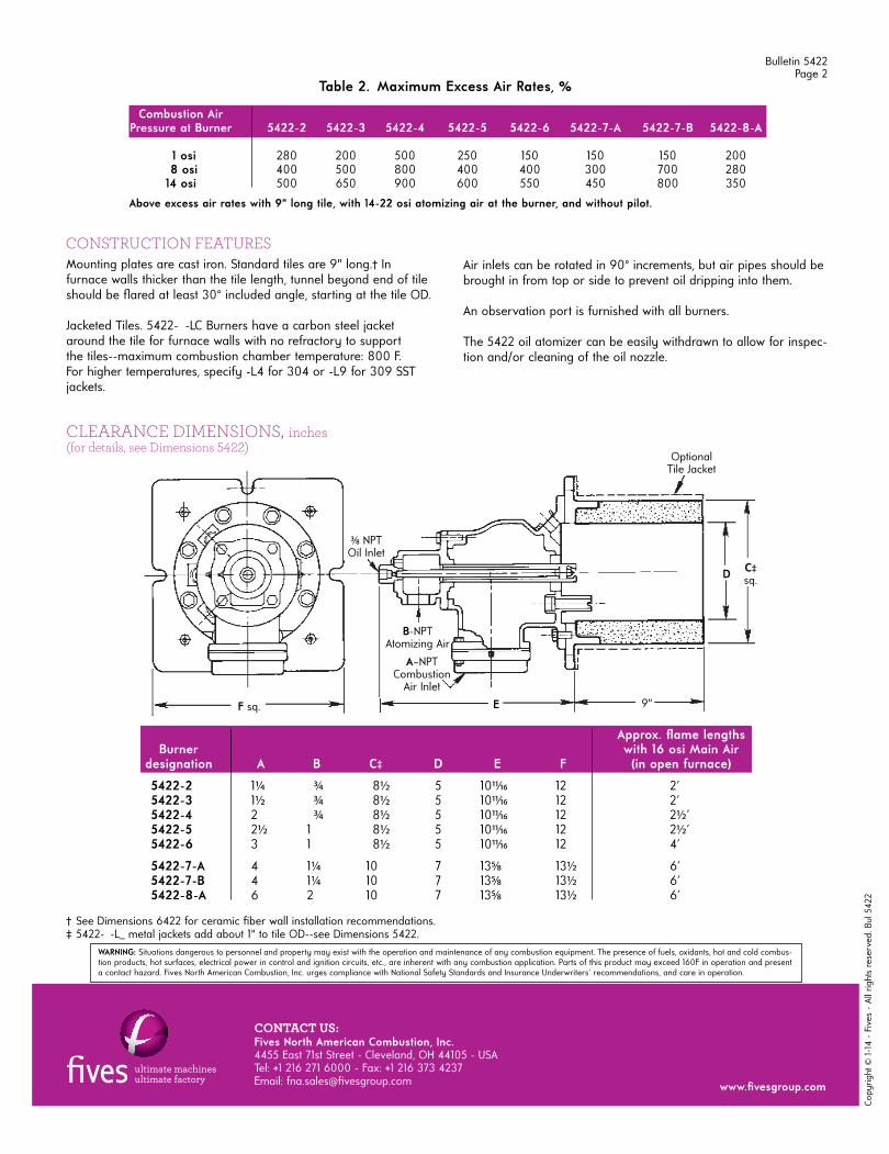
Mounting plates are cast iron. Standard tiles are 9" long.† In furnace walls thicker than the tile length, tunnel beyond end of tile should be fl ared at least 30° included angle, starting at the tile OD.
Jacketed Tiles. 5422- -LC Burners have a carbon steel jacket around the tile for furnace walls with no refractory to support the tiles--maximum combustion chamber temperature: 800 F. For higher temperatures, specify -L4 for 304 or -L9 for 309 SST jackets.
CONSTRUCTION FEATURESAir inlets can be rotated in 90° increments, but air pipes should be brought in from top or side to prevent oil dripping into them.
An observation port is furnished with all burners.
The 5422 oil atomizer can be easily withdrawn to allow for inspec-tion and/or cleaning of the oil nozzle.
OptionalTile Jacket
A–NPTCombustion
Air Inlet
E
D C‡sq.
9"F sq.
Table 2. Maximum Excess Air Rates, %
Combustion Air Pressure at Burner 5422-2 5422-3 5422-4 5422-5 5422-6 5422-7-A 5422-7-B 5422-8-A
1 osi 280 200 500 250 150 150 150 200 8 osi 400 500 800 400 400 300 700 28014 osi 500 650 900 600 550 450 800 350
Above excess air rates with 9" long tile, with 14-22 osi atomizing air at the burner, and without pilot.
CLEARANCE DIMENSIONS, inches(for details, see Dimensions 5422)
Approx. fl ame lengthsBurner with 16 osi Main Air
designation A B C‡ D E F (in open furnace)
5422-2 1¼ ¾ 8½ 5 1011⁄16 12 2' 5422-3 1½ ¾ 8½ 5 1011⁄16 12 2' 5422-4 2 ¾ 8½ 5 1011⁄16 12 2½ '
5422-5 2½ 1 8½ 5 1011⁄16 12 2½ '5422-6 3 1 8½ 5 1011⁄16 12 4'
5422-7-A 4 1¼ 10 7 135⁄8 13½ 6'5422-7-B 4 1¼ 10 7 135⁄8 13½ 6'5422-8-A 6 2 10 7 135⁄8 13½ 6'
† See Dimensions 6422 for ceramic fi ber wall installation recommendations.‡ 5422- -L_ metal jackets add about 1" to tile OD--see Dimensions 5422.
3⁄8 NPTOil Inlet
B-NPTAtomizing Air
WARNING: Situations dangerous to personnel and property may exist with the operation and maintenance of any combustion equipment. The presence of fuels, oxidants, hot and cold combus-tion products, hot surfaces, electrical power in control and ignition circuits, etc., are inherent with any combustion application. Parts of this product may exceed 160F in operation and present a contact hazard. Fives North American Combustion, Inc. urges compliance with National Safety Standards and Insurance Underwriters' recommendations, and care in operation.
Copy
right
© 1
-14
- Fi
ves
- Al
l rig
hts
rese
rved
. Bul
542
2
CONTACT US:Fives North American Combustion, Inc. 4455 East 71st Street - Cleveland, OH 44105 - USA Tel: +1 216 271 6000 - Fax: +1 216 373 4237Email: fna.sales@fi vesgroup.com www.fi vesgroup.com
OIL ATOMIZERSSteam or Compressed Air Nozzle Mix
Bulletin 5622/23
S eptember 201 4
0 25 50 75 1 00 1 25
-1 -B -1 -A
-0-B
-0-A
-01 -B
-01 -A
-02-B
-02-A
250
200
1 50
1 00
50
0
Oil A
tom
izin
g C
ap
ac
ity
gp
h (
ba
se
d o
n 1
00
SS
U v
isc
os
ity
)
S team or Air Pressure at Atomizer in psi
0 25 50 75 1 00 1 25
-1 -B -1 -A
-0-B
-0-A
-01 -B
-01 -A
-02-B
-02-A
500
400
300
200
1 00
0
Ste
am
Co
ns
um
pti
on
lb
/hr
S team Pressure at Atomizer in psi
WARNING: Situations dangerous to personnel and property may exist with the operation and maintenance of any combustion equipment. The presence of fuels, oxidants, hot and cold combustion products, hot surfaces, electrical power in control and ignition circuits, etc., are inherent with any combustion application. Parts of this product may exceed 160F in operation and present a contact hazard. Fives North American Combustion, Inc. urges compliance with National Safety Standards and insurance Underwriters recommendations, and care in operation.
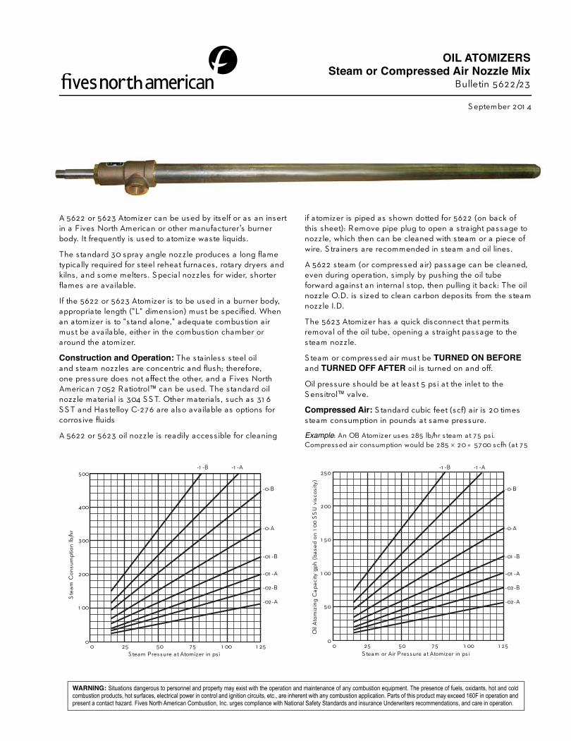
A 5622 or 5623 Atomizer can be used by itself or as an insert
in a Fives North American or other manufacturer’s burner
body. It frequently is used to atomize waste liquids.
The standard 30 spray angle nozzle produces a long fl ame
typically required for steel reheat furnaces, rotary dryers and
kilns, and some melters. S pecial nozzles for wider, shorter
fl ames are available.
If the 5622 or 5623 Atomizer is to be used in a burner body,
appropriate length ("L" dimension) must be specifi ed. When
an atomizer is to "stand alone," adequate combustion air
must be available, either in the combustion chamber or
around the atomizer.
Construction and Operation: The stainless steel oil
and steam nozzles are concentric and fl ush; therefore,
one pressure does not affect the other, and a Fives North
American 7052 Ratiotrol™ can be used. The standard oil
nozzle material is 304 S S T. Other materials , such as 31 6
S S T and Hastelloy C-276 are also available as options for
corrosive fl uids
A 5622 or 5623 oil nozzle is readily accessible for cleaning
if atomizer is piped as shown dotted for 5622 (on back of
this sheet): Remove pipe plug to open a straight passage to
nozzle, which then can be cleaned with steam or a piece of
wire. S trainers are recommended in steam and oil lines.
A 5622 steam (or compressed air) passage can be cleaned,
even during operation, s imply by pushing the oil tube
forward against an internal stop, then pulling it back: The oil
nozzle O.D. is s ized to clean carbon deposits from the steam
nozzle I.D.
The 5623 Atomizer has a quick disconnect that permits
removal of the oil tube, opening a straight passage to the
steam nozzle.
S team or compressed air must be TURNED ON BEFOREand TURNED OFF AFTER oil is turned on and off.
Oil pressure should be at least 5 psi at the inlet to the
S ensitrol™ valve.
Compressed Air: S tandard cubic feet (scf) air is 20 times
steam consumption in pounds at same pressure.
Example: An OB Atomizer uses 285 lb/hr steam at 75 psi.
Compressed air consumption would be 285 20 = 5700 scfh (at 75
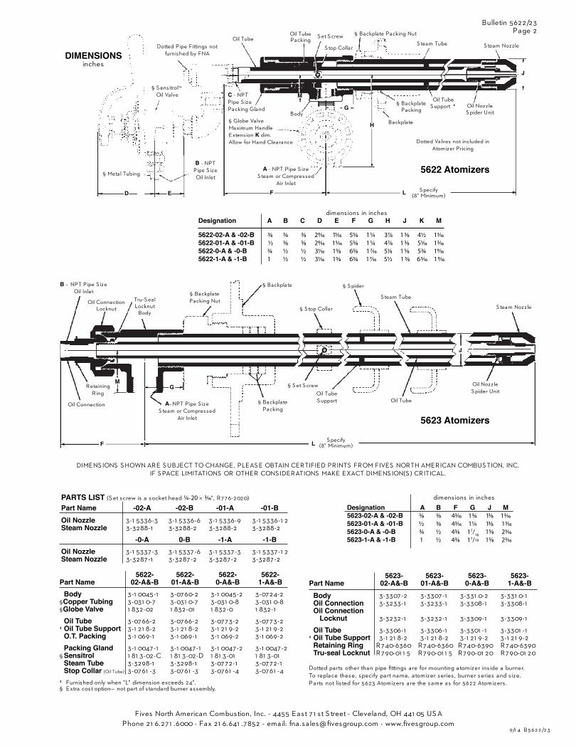
Designation A B C D E F G H J K M
5622-02-A & -02-B 3⁄8 3⁄8 3⁄8 29⁄16 15⁄16 55⁄8 1 ¼ 37⁄8 1 3⁄8 4½ 13⁄16
5622-01-A & -01-B ½ 3⁄8 3⁄8 29⁄16 15⁄16 55⁄8 1 ¼ 47⁄8 1 3⁄8 51⁄16 13⁄16 5622-0-A & -0-B ¾ ½ ½ 31⁄16 15⁄8 65⁄8 1 7⁄16 51⁄8 1 5⁄8 5¾ 19⁄16
5622-1-A & -1-B 1 ½ ½ 31⁄16 15⁄8 65⁄8 1 7⁄16 5½ 1 5⁄8 6 5⁄16 1 9⁄16
5622- 5622- 5622- 5622-Part Name 02-A&-B 01-A&-B 0-A&-B 1-A&-B
Body 3-1 0045-1 3-0760-2 3-1 0045-2 3-0724-2
§Copper Tubing 3-031 0-7 3-031 0-7 3-031 0-8 3-031 0-8
§Globe Valve 1 832-02 1 832-01 1 832-0 1 832-1
Oil Tube 3-0766-2 3-0766-2 3-0773-2 3-0773-2
‡ Oil Tube Support 3-1 21 8-2 3-1 21 8-2 3-1 21 9-2 3-1 21 9-2
O.T. Packing 3-1 069-1 3-1 069-1 3-1 069-2 3-1 069-2
Packing Gland 3-1 0047-1 3-1 0047-1 3-1 0047-2 3-1 0047-2
§ Sensitrol 1 81 3-02-C 1 81 3-02-D 1 81 3-01 1 81 3-01
Steam Tube 3-3298-1 3-3298-1 3-0772-1 3-0772-1
Stop Collar (Oil Tube) 3-0761 -3 3-0761 -3 3-0761 -4 3-0761 -4
‡ Furnished only when "L" dimension exceeds 24".
§ Extra cost option— not part of standard burner assembly.
DIMENSIONSinches
Dotted Pipe Fittings not
furnished by FNA
Oil Tube
Oil Tube
Packing
S top CollarS team Tube
S team Nozzle
Oil Nozzle
S pider Unit
Oil Tube
S upport ठBackplate
Packing
Backplate
C - NPT
Pipe S ize
Packing Gland
B - NPT
Pipe S ize
Oil Inlet§ Metal Tubing
§ S ensitrol™
Oil Valve
S et S crew
§ Globe Valve
Maximum Handle
Extension K dim.
Allow for Hand Clearance
A - NPT Pipe S ize
S team or Compressed
Air Inlet
§ Backplate Packing Nut
D E F S pecify
(8" Minimum)
M
G
H
Body
B – NPT Pipe S ize
Oil Inlet
Oil Connection
Locknut
Tru-S eal
Locknut
Body
§ Backplate
Packing Nut
Oil Connection
Retaining
Ring
A– NPT Pipe S ize
S team or Compressed
Air Inlet
§ Backplate
Packing
§ S et S crew
Oil Tube
S upport Oil Tube
Oil Nozzle
S pider Unit
S team Nozzle
S team Tube
§ S pider
§ S top Collar
§ Backplate
G
F
M
L S pecify
(8" Minimum)
L
5623- 5623- 5623- 5623-Part Name 02-A&-B 01-A&-B 0-A&-B 1-A&-B
Body 3-3307-2 3-3307-1 3-331 0-2 3-331 0-1
Oil Connection 3-3233-1 3-3233-1 3-3308-1 3-3308-1
Oil Connection Locknut 3-3232-1 3-3232-1 3-3309-1 3-3309-1
Oil Tube 3-3306-1 3-3306-1 3-3301 -1 3-3301 -1
‡ Oil Tube Support 3-1 21 8-2 3-1 21 8-2 3-1 21 9-2 3-1 21 9-2
Retaining Ring R740-6360 R740-6360 R740-6390 R740-6390
Tru-seal Locknut R790-01 1 5 R790-01 1 5 R790-01 20 R790-01 20
Dotted parts other than pipe fi ttings are for mounting atomizer ins ide a burner.
To replace these, specify part name, atomizer series , burner series and s ize.
Parts not lis ted for 5623 Atomizers are the same as for 5622 Atomizers .
Designation A B F G J M 5623-02-A & -02-B 3⁄8 3⁄8 43⁄16 1¾ 13⁄8 13⁄16 5623-01-A & -01-B ½ 3⁄8 43⁄16 1¼ 13⁄8 13⁄16
5623-0-A & -0-B ¾ ½ 43⁄8 17/16 15⁄8 23⁄16
5623-1-A & -1-B 1 ½ 43⁄8 17/16 15⁄8 23⁄16
PARTS LIST (S et screw is a socket head ¼ -20 3⁄16", R776-2020)
Part Name -02-A -02-B -01-A -01-BOil Nozzle 3-1 5336-3 3-1 5336-6 3-1 5336-9 3-1 5336-1 2
Steam Nozzle 3-3288-1 3-3288-2 3-3288-2 3-3288-2
-0-A 0-B -1-A -1-BOil Nozzle 3-1 5337-3 3-1 5337-6 3-1 5337-3 3-1 5337-1 2
Steam Nozzle 3-3287-1 3-3287-2 3-3287-2 3-3287-2
Dotted Valves not included in
Atomizer Pricing
dimensions in inches
dimensions in inches
Bulletin 5622/23
Page 2
5623 Atomizers
5622 Atomizers
J
J
DIMENS IONS S HOWN ARE S UBJECT TO CHANGE. PLEAS E OBTAIN CERTIFIED PRINTS FROM FIVES NORTH AMERICAN COMBUS TION, INC.
IF S PACE LIMITATIONS OR OTHER CONS IDERATIONS MAKE EXACT DIMENS ION(S ) CRITICAL.
9/1 4 B 5 62 2 /2 3
Fives North American Combustion, Inc. - 4455 East 7 1 st S treet - Cleveland, OH 441 05 US A
Phone 21 6.271 .6000 - Fax 21 6.641 .7852 - email: fna.sales@fi vesgroup.com - www.fi vesgroup.com
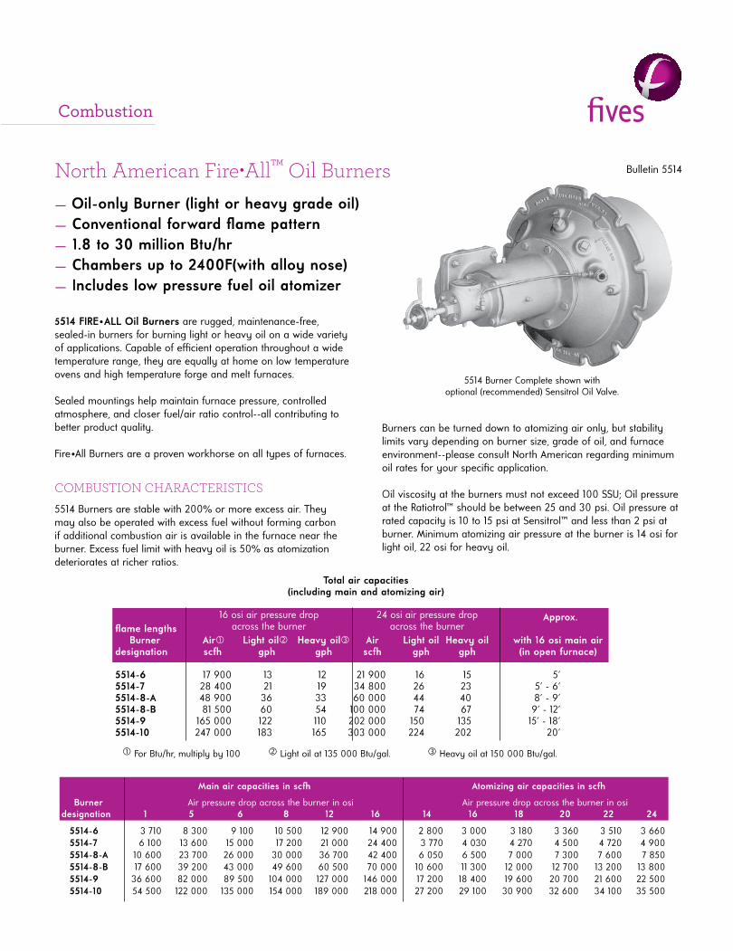
North American Fire•All™ Oil Burners Bulletin 5514
5514 FIRE•ALL Oil Burners are rugged, maintenance-free, sealed-in burners for burning light or heavy oil on a wide variety of applications. Capable of effi cient operation throughout a wide temperature range, they are equally at home on low temperature ovens and high temperature forge and melt furnaces.
Sealed mountings help maintain furnace pressure, control led atmosphere, and closer fuel/air ratio control--all contributing to better product quality.
Fire•All Burners are a proven workhorse on all types of furnaces.
COMBUSTION CHARACTERISTICS
5514 Burners are stable with 200% or more excess air. They may also be operated with excess fuel without forming carbon if additional combustion air is available in the furnace near the burner. Excess fuel limit with heavy oil is 50% as atomization deteriorates at richer ratios.
5514 Burner Complete shown withoptional (recommended) Sensitrol Oil Valve.
— Oil-only Burner (light or heavy grade oil)— Conventional forward fl ame pattern— 1.8 to 30 million Btu/hr— Chambers up to 2400F(with alloy nose)— Includes low pressure fuel oil atomizer
Approx. fl ame lengths Burner Air Light oil Heavy oil Air Light oil Heavy oil with 16 osi main airdesignation scfh gph gph scfh gph gph (in open furnace) 5514-6 17 900 13 12 21 900 16 15 5' 5514-7 28 400 21 19 34 800 26 23 5' - 6' 5514-8-A 48 900 36 33 60 000 44 40 8' - 9' 5514-8-B 81 500 60 54 100 000 74 67 9' - 12'5514-9 165 000 122 110 202 000 150 135 15' - 18'5514-10 247 000 183 165 303 000 224 202 20'
For Btu/hr, multiply by 100 Light oil at 135 000 Btu/gal. Heavy oil at 150 000 Btu/gal.
16 osi air pressure dropacross the burner
Total air capacities(including main and atomizing air)
24 osi air pressure dropacross the burner
Main air capacities in scfh Atomizing air capacities in scfh
Burner Air pressure drop across the burner in osi Air pressure drop across the burner in osidesignation 1 5 6 8 12 16 14 16 18 20 22 24
5514-6 3 710 8 300 9 100 10 500 12 900 14 900 2 800 3 000 3 180 3 360 3 510 3 660 5514-7 6 100 13 600 15 000 17 200 21 000 24 400 3 770 4 030 4 270 4 500 4 720 4 900 5514-8-A 10 600 23 700 26 000 30 000 36 700 42 400 6 050 6 500 7 000 7 300 7 600 7 850 5514-8-B 17 600 39 200 43 000 49 600 60 500 70 000 10 600 11 300 12 000 12 700 13 200 13 800 5514-9 36 600 82 000 89 500 104 000 127 000 146 000 17 200 18 400 19 600 20 700 21 600 22 500 5514-10 54 500 122 000 135 000 154 000 189 000 218 000 27 200 29 100 30 900 32 600 34 100 35 500
Burners can be turned down to atomizing air only, but stability limits vary depending on burner size, grade of oil, and furnace environment--please consult North American regarding minimum oil rates for your specifi c application.
Oil viscosity at the burners must not exceed 100 SSU; Oil pressure at the Ratiotrol™ should be between 25 and 30 psi. Oil pressure at rated capacity is 10 to 15 psi at Sensitrol™ and less than 2 psi at burner. Minimum atomizing air pressure at the burner is 14 osi for light oil, 22 osi for heavy oil.
Combustion
Flame Supervision. An ultraviolet cell‡ will monitor pilot or main fl ame on gas or oil. For maximum safety, Fives urges interrupted pilots when fl ame safeguards are used--pilots should be on only for a preset ignition period (usually 15 seconds), aft er which fl ame supervision detects main fi re only. Adapters for mounting fl ame detection devices on 5514 Burners are tabulated on Bulletin 8832.
Tile/Installation. Burner tiles are cast refractory rated for 2800 F furnace temperature. They should be supported securely in the furnace wall by a layer of castable refractory (not insulation) at least 9" thick all around the tile, extending back to the furnace shell and securely anchored to it. (See Supplement DF-M1.)
Tiles are replaceable in the fi eld except for the 5514-10, whose mounting must be returned to the factory for tile replacement (or purchase a spare mounting plate with a tile cast onto it).
Complete burners include tile, mounting plate, and an observation port into which a small quantity of atomizing air is introduced to keep the glass clear. Order Sensitrol™ Oil Valve and pilot tips separately. See 5514 Dimen-sion Sheet for recommended Sensitrol™ oil valve and premix pilot tip.
Jacketed Tile options are available for applications where the tile is not supported by furnace refractory. Jackets are available in three diff erent metals and have maximum temperature ratings for each. They must be protected with suffi cient insulation so as not to exceed rated temperature.The maximum temperature rating for jacket metals depends upon fre-quency of heat-up/cool-down cycles. As an example, batch annealing fur-naces that are heated and cooled every day should use the "intermittent exposure" ratings. Continuous annealing furnaces that remain at the same temperature for months at a time, can use the higher "continuous" rating.
Continuous IntermittentDesignation Jacket Metal max. temp. exposure
5514- -LC carbon steel 700 F 700 F5514- -L4 304 stainless 1600 F 1500 F5514- -L9 309 stainless 1900 F 1800 F
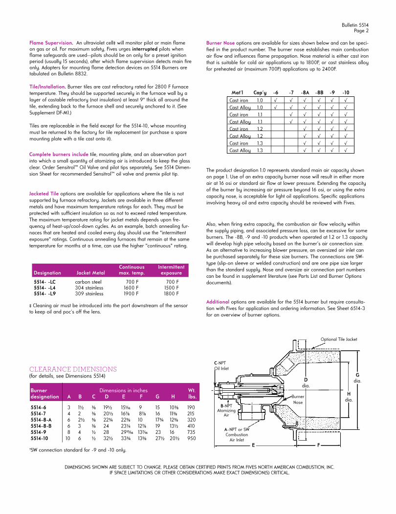
CLEARANCE DIMENSIONS (for details, see Dimensions 5514)
Burner Dimensions in inches Wt.designation A B C D E F G H lbs.
5514-6 3 1½ 3⁄8 19½ 151⁄16 9 15 103⁄8 1905514-7 4 2 3⁄8 20½ 167⁄8 87⁄8 16 113⁄8 2155514-8-A 6 2½ 3⁄8 22¾ 223⁄8 10 17¾ 123⁄8 320 5514-8-B 6 3 3⁄8 24 23¼ 127⁄8 19 13½ 4105514-9 8 4 ½ 28 2915⁄16 137⁄16 23 16 7355514-10 10 6 ½ 32½ 33¾ 135⁄8 27½ 20½ 950
Optional Tile Jacket
Ddia.
Gdia.
Hdia.
FE
A–NPT or SWCombustion
Air Inlet
DIMENSIONS SHOWN ARE SUBJECT TO CHANGE. PLEASE OBTAIN CERTIFIED PRINTS FROM FIVES NORTH AMERICAN COMBUSTION, INC.IF SPACE LIMITATIONS OR OTHER CONSIDERATIONS MAKE EXACT DIMENSION(S) CRITICAL.
Bulletin 5514Page 2
Additional options are available for the 5514 burner but require consulta-tion with Fives for application and ordering information. See Sheet 6514-3 for an overview of burner options.
Burner Nose options are available for sizes shown below and can be speci-fi ed in the product number. The burner nose establishes main combustion air fl ow and infl uences fl ame propagation. Nose material is either cast iron that is suitable for cold air applications up to 1800F, or cast stainless alloy for preheated air (maximum 700F) applications up to 2400F.
Mat'l Cap'y -6 -7 -8A -8B -9 -10
Cast iron 1.0 √ √ √ √ √ √ Cast Alloy 1.0 √ √ √ √ √ √ Cast iron 1.1 √ √ √ √ √ Cast Alloy 1.1 √ √ √ √ √ Cast iron 1.2 √ √ √ √ Cast Alloy 1.2 √ √ √ √ Cast iron 1.3 √ √ √ √ Cast Alloy 1.3 √ √ √ √
The product designation 1.0 represents standard main air capacity shown on page 1. Use of an extra capacity burner nose will result in either more air at 16 osi or standard air fl ow at lower pressure. Extending the capacity of the burner by increasing air pressure beyond 16 osi, or using the extra capacity nose, is acceptable for light oil applications. Specifi c applications involving heavy oil and extra capacity should be reviewed with Fives.
Also, when fi ring extra capacity, the combustion air fl ow velocity within the supply piping, and associated pressure loss, can be excessive for some burners. The -8B, -9 and -10 products when operated at 1.2 or 1.3 capacity will develop high pipe velocity based on the burner’s air connection size. As an alternative to increasing blower pressure, an oversized air inlet can be purchased separately for these size burners. The connections are SW-type (slip-on sleeve or welded construction) and are one pipe size larger than the standard supply. Nose and oversize air connection part numbers can be found in supplement literature (see Parts List and Burner Options documents).
Burner Nose
B-NPTAtomizing
Air
‡ Cleaning air must be introduced into the port downstream of the sensor to keep oil and poc's off the lens.
†SW connection standard for -9 and -10 only.
C-NPTOil Inlet
Bulletin 5514Page 3
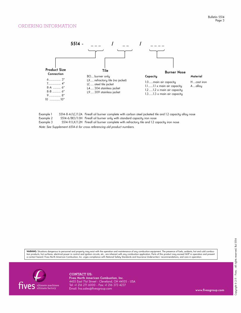
ORDERING INFORMATION
Example 1 5514-8-A / LC / 1.2A Fireall oil burner complete with carbon steel jacketed tile and 1.2 capacity alloy noseExample 2 5514-6 / BO / 1.0H Fireall oil burner only with standard capacity iron noseExample 3 5514-9 / LX / 1.2H Fireall oil burner complete with refractory tile and 1.2 capacity iron nose
Note: See Supplement 6514-6 for cross referencing old product numbers.
5514 - _ _ _ / _ _ / _ _ _ _
Product Size Connection
6 ................. 3" 7.................. 4"
8-A ........... 6"8-B ............ 6"
9 ................. 8" 10 ............... 10"
Tile BO .... burner only
LX ..... refractory tile (no jacket)LC ..... steel tile jacketL4 ..... 304 stainless jacketL9 ..... 309 stainless jacket
Burner NoseCapacity Material
1.0 ......main air capacity H ....cast iron1.1 .......1.1 x main air capacity A ....alloy1.2 ......1.2 x main air capacity1.3 ......1.3 x main air capacity
Copy
right
© 2
-11
- Fi
ves
- Al
l rig
hts
rese
rved
. Bul
551
4
CONTACT US:Fives North American Combustion, Inc. 4455 East 71st Street - Cleveland, OH 44105 - USA Tel: +1 216 271 6000 - Fax: +1 216 373 4237Email: fna.sales@fi vesgroup.com www.fi vesgroup.com
WARNING: Situations dangerous to personnel and property may exist with the operation and maintenance of any combustion equipment. The presence of fuels, oxidants, hot and cold combus-tion products, hot surfaces, electrical power in control and ignition circuits, etc., are inherent with any combustion application. Parts of this product may exceed 160F in operation and present a contact hazard. Fives North American Combustion, Inc. urges compliance with National Safety Standards and Insurance Underwriters' recommendations, and care in operation.
North American Full Emulsion Oil Atomizers Bulletin 5642
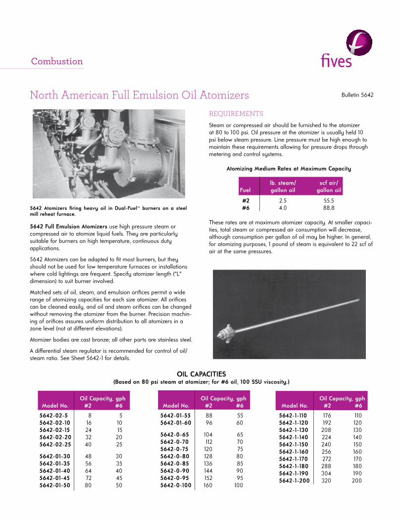
5642 Atomizers fi ring heavy oil in Dual-Fuel™ burners on a steel mill reheat furnace.
5642 Full Emulsion Atomizers use high pressure steam or compressed air to atomize liquid fuels. They are particularly suitable for burners on high temperature, continuous duty applications.
5642 Atomizers can be adapted to fi t most burners, but they should not be used for low temperature furnaces or installations where cold lightings are frequent. Specify atomizer length ("L" dimension) to suit burner involved.
Matched sets of oil, steam, and emulsion orifi ces permit a wide range of atomizing capacities for each size atomizer. All orifi ces can be cleaned easily, and oil and steam orifi ces can be changed without removing the atomizer from the burner. Precision machin-ing of orifi ces assures uniform distribution to all atomizers in a zone level (not at diff erent elevations).
Atomizer bodies are cast bronze; all other parts are stainless steel.
A diff erential steam regulator is recommended for control of oil/steam ratio. See Sheet 5642-1 for details.
REQUIREMENTS
Steam or compressed air should be furnished to the atomizer at 80 to 100 psi. Oil pressure at the atomizer is usually held 10 psi below steam pressure. Line pressure must be high enough to maintain these requirements allowing for pressure drops through metering and control systems.
Atomizing Medium Rates at Maximum Capacity
lb. steam/ scf air/Fuel gallon oil gallon oil
#2 2.5 55.5 #6 4.0 88.8
These rates are at maximum atomizer capacity. At smaller capaci-ties, total steam or compressed air consumption will decrease, although consumption per gallon of oil may be higher. In general, for atomizing purposes, 1 pound of steam is equivalent to 22 scf of air at the same pressures.
OIL CAPACITIES(Based on 80 psi steam at atomizer; for #6 oil, 100 SSU viscosity.)
Oil Capacity, gph Model No. #2 #6
5642-02-5 8 5 5642-02-10 16 10 5642-02-15 24 15 5642-02-20 32 20 5642-02-25 40 25
5642-01-30 48 30 5642-01-35 56 35 5642-01-40 64 40 5642-01-45 72 45 5642-01-50 80 50
Oil Capacity, gph Model No. #2 #6 5642-01-55 88 55 5642-01-60 96 60
5642-0-65 104 65 5642-0-70 112 70 5642-0-75 120 75 5642-0-80 128 80 5642-0-85 136 85 5642-0-90 144 90 5642-0-95 152 95 5642-0-100 160 100
Oil Capacity, gph Model No. #2 #6
5642-1-110 176 110 5642-1-120 192 120 5642-1-130 208 130 5642-1-140 224 140 5642-1-150 240 150 5642-1-160 256 160 5642-1-170 272 170 5642-1-180 288 180 5642-1-190 304 190 5642-1-200 320 200
Combustion
Bulletin 5642Page 2
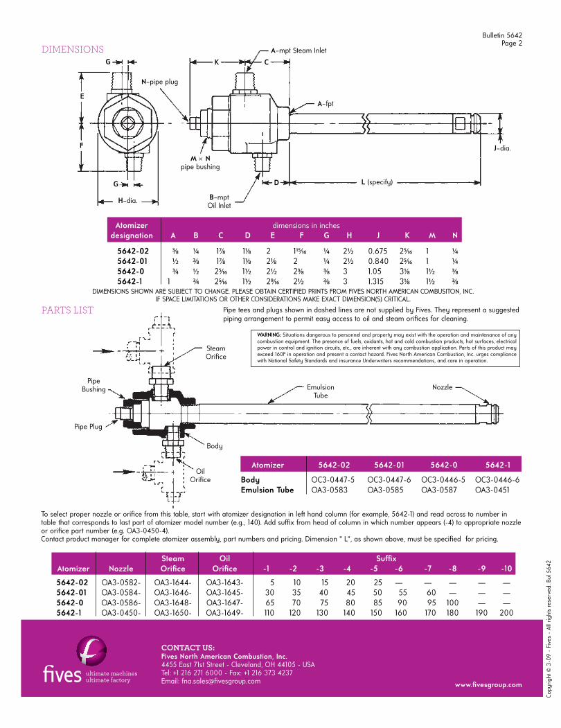
DIMENSIONSG
E
F
G
H–dia.
M Npipe bushing
B–mptOil Inlet
D
A–fpt
J–dia.
A–mpt Steam Inlet
K C
L (specify)
Atomizer dimensions in inches designation A B C D E F G H J K M N
5642-02 3⁄8 ¼ 17⁄8 11⁄8 2 115⁄16 ¼ 2½ 0.675 25⁄16 1 ¼ 5642-01 ½ 3⁄8 17⁄8 11⁄8 21⁄8 2 ¼ 2½ 0.840 25⁄16 1 ¼ 5642-0 ¾ ½ 25⁄16 1½ 2½ 23⁄8 3⁄8 3 1.05 31⁄8 1½ 3⁄85642-1 1 ¾ 25⁄16 1½ 29⁄16 2½ 3⁄8 3 1.315 31⁄8 1½ 3⁄8
Pipe tees and plugs shown in dashed lines are not supplied by Fives. They represent a suggested piping arrangement to permit easy access to oil and steam orifi ces for cleaning.
PARTS LIST
Steam Oil Suffi xAtomizer Nozzle Orifi ce Orifi ce -1 -2 -3 -4 -5 -6 -7 -8 -9 -10
5642-02 OA3-0582- OA3-1644- OA3-1643- 5 10 15 20 25 — — — — — 5642-01 OA3-0584- OA3-1646- OA3-1645- 30 35 40 45 50 55 60 — — — 5642-0 OA3-0586- OA3-1648- OA3-1647- 65 70 75 80 85 90 95 100 — — 5642-1 OA3-0450- OA3-1650- OA3-1649- 110 120 130 140 150 160 170 180 190 200
To select proper nozzle or orifi ce from this table, start with atomizer designation in left hand column (for example, 5642-1) and read across to number in table that corresponds to last part of atomizer model number (e.g., 140). Add suffi x from head of column in which number appears (-4) to appropriate nozzle or orifi ce part number (e.g. OA3-0450-4).Contact product manager for complete atomizer assembly, part numbers and pricing. Dimension " L", as shown above, must be specifi ed for pricing.
PipeBushing
Pipe Plug
OilOrifi ce
Body
SteamOrifi ce
EmulsionTube
Nozzle
Atomizer 5642-02 5642-01 5642-0 5642-1
Body OC3-0447-5 OC3-0447-6 OC3-0446-5 OC3-0446-6 Emulsion Tube OA3-0583 OA3-0585 OA3-0587 OA3-0451
N–pipe plug
WARNING: Situations dangerous to personnel and property may exist with the operation and maintenance of any combustion equipment. The presence of fuels, oxidants, hot and cold combustion products, hot surfaces, electrical power in control and ignition circuits, etc., are inherent with any combustion application. Parts of this product may exceed 160F in operation and present a contact hazard. Fives North American Combustion, Inc. urges compliance with National Safety Standards and insurance Underwriters recommendations, and care in operation.
Copy
right
© 3
-09
- Fi
ves
- Al
l rig
hts
rese
rved
. Bul
564
2
CONTACT US:Fives North American Combustion, Inc. 4455 East 71st Street - Cleveland, OH 44105 - USA Tel: +1 216 271 6000 - Fax: +1 216 373 4237Email: fna.sales@fi vesgroup.com www.fi vesgroup.com
DIMENSIONS SHOWN ARE SUBJECT TO CHANGE. PLEASE OBTAIN CERTIFIED PRINTS FROM FIVES NORTH AMERICAN COMBUSITON, INC.IF SPACE LIMITATIONS OR OTHER CONSIDERATIONS MAKE EXACT DIMENSION(S) CRITICAL.

GET IN TOUCH!
KILNS AND FURNACES Email: [email protected]
SPARE PARTSEmail: [email protected]
TECHNICAL SUPPORTEmail: [email protected]
HEADQUARTERS & GLOBAL SALES
HEADQUARTERSCarr. Saltillo - Monterrey No. 100 (Km. 62.5) Santa Catarina, N.L. 66359, México.
Phone: +52 (81) 8151 0800 US Phone: +1 (855) 299 9566
SALES AND SERVICE OFFICES
USA / CANADAPhone: +1 (450) 813 6901 Mobile: +1 (514) 268 2545
EUROPEPhone: +44 (0) 7717 880888 Email: [email protected]
You can also leave us a message describing your project on our website and we will be happy to contact with you!
Request a Quote