Embed Size (px)
Citation preview
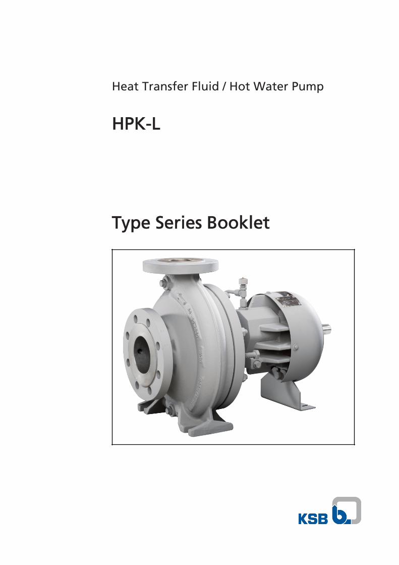
Heat Transfer Fluid / Hot Water Pump
HPK-L
Type Series Booklet

Legal information/Copyright
Type Series Booklet HPK-L
All rights reserved. The contents provided herein must neither be distributed, copied, reproduced,edited or processed for any other purpose, nor otherwise transmitted, published or made available toa third party without the manufacturer's express written consent.
Subject to technical modification without prior notice.
© KSB Aktiengesellschaft, Frankenthal 04.04.2016
Contents
Centrifugal Pumps with Shaft Seal ...................................................................................................................4
Heat Transfer Fluid / Hot Water Pumps ......................................................................................................................... 4
HPK-L .......................................................................................................................................................................... 4
Main applications ................................................................................................................................................ 4
Operating data .................................................................................................................................................... 4
Designation .......................................................................................................................................................... 4
Design details ....................................................................................................................................................... 4
Automation (Europe only) .................................................................................................................................. 5
Materials .............................................................................................................................................................. 5
Coating and preservation ................................................................................................................................... 6
Product benefits .................................................................................................................................................. 6
Acceptance tests and warranty ........................................................................................................................... 6
Pressure and temperature limits ......................................................................................................................... 6
Technical data ...................................................................................................................................................... 7
Selection charts ................................................................................................................................................... 9
Dimensions and connections ............................................................................................................................ 14
Flange design ..................................................................................................................................................... 17
Scope of supply .................................................................................................................................................. 17
General assembly drawing with list of components ....................................................................................... 19
Detailed designation ......................................................................................................................................... 21
Contents
3
Centrifugal Pumps with Shaft Seal
Heat Transfer Fluid / Hot Water Pumps
HPK-L
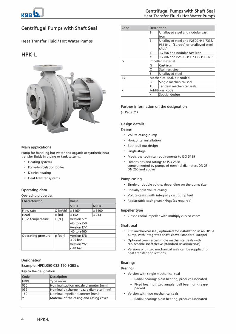
Main applications
Pump for handling hot water and organic or synthetic heattransfer fluids in piping or tank systems.
▪ Heating systems
▪ Forced-circulation boiler
▪ District heating
▪ Heat transfer systems
Operating data
Operating properties
Characteristic Value
50 Hz 60 HzFlow rate Q [m3/h] ≤ 1160 ≤ 1400Head H [m] ≤ 162 ≤ 233Fluid temperature T [°C] Version S/Z:
-40 to +350Version E/Y:-40 to +400
Operating pressure p [bar] Version E/S:≤ 25 barVersion Y/Z:≤ 40 bar
Designation
Example: HPKL050-032-160 EGBS x
Key to the designation
Code DescriptionHPKL Type series050 Nominal suction nozzle diameter [mm]032 Nominal discharge nozzle diameter [mm]160 Nominal impeller diameter [mm]Y Material of the casing and casing cover
Code DescriptionS Unalloyed steel and nodular cast
ironE Unalloyed steel and P250GH/ 1.7335/
P355NL1 (Europe) or unalloyed steel(Asia)
Z 1.7706 and nodular cast ironY 1.7706 and P250GH/ 1.7335/ P355NL1
G Impeller materialG Cast ironC Stainless steelE Unalloyed steel
BS Mechanical seal, air-cooledBS Single mechanical sealTL Tandem mechanical seals
x Additional codex Special design
Further information on the designation
(⇨ Page 21)
Design details
Design
▪ Volute casing pump
▪ Horizontal installation
▪ Back pull-out design
▪ Single-stage
▪ Meets the technical requirements to ISO 5199
▪ Dimensions and ratings to ISO 2858complemented by pumps of nominal diameters DN 25,DN 200 and above
Pump casing
▪ Single or double volute, depending on the pump size
▪ Radially split volute casing
▪ Volute casing with integrally cast pump feet
▪ Replaceable casing wear rings (as required)
Impeller type
▪ Closed radial impeller with multiply curved vanes
Shaft seal
▪ KSB mechanical seal, optimised for installation in an HPK-Lpump, with integrated shaft sleeve (standard Europe)
▪ Optional commercial single mechanical seals withreplaceable shaft sleeve (standard Asia/Americas)
▪ Versions with two mechanical seals can be supplied forheat transfer applications.
Bearings
Bearings:
▪ Version with single mechanical seal
– Radial bearing: plain bearing, product-lubricated
– Fixed bearings: two angular ball bearings, grease-packed
▪ Version with two mechanical seals
– Radial bearing: plain bearing, product-lubricated
Centrifugal Pumps with Shaft SealHeat Transfer Fluid / Hot Water Pumps
4 HPK-L
– Fixed bearing: one deep groove ball bearing or onefour-point bearing (depending on the pump size),grease-packed
Bearing bracket designation
Example: CS50
Bearing bracket designation
Code DescriptionCS Bearing bracket50 Size
Bearings used
Design Bearing bracket Plain bearing Ball bearingOne mechanical seal CS40 SSiC 2x7307
CS50 SSiC 2x7307CS60 SSiC 2x7309CS80 SSiC 2x7313
Two mechanical seals CS40 SSiC 1x6307 or QJ307CS50 SSiC 1x6307 or QJ307CS60 SSiC 1x6309CS80 SSiC 1x6313 or QJ313
Automation (Europe only)
Automation options:
▪ Hyamaster
▪ hyatronic
▪ PumpDrive
Materials
Overview of available materials (Europe)
Description Material variant
SG SC EG EC ZG ZC YG YCVolute casing GP240GH+N 1.7706Casing cover EN-GJS-400-18-LT P250GH/1.7335/P355NL1) EN-GJS-40-18-LT P250GH/1.7335/P355NL1)
Impeller EN-GJL-250 1.4408 EN-GJL-250 1.4408 EN-GJL-250 1.4408 EN-GJL-250 1.4408Shaft 1.4021+QT800Shaft sleeve 1.4021+QT800Bearing bracket EN-GJS-400-18-LTSupport foot SteelCasing wear ring None2) None3) None2) None3) None2) None3) None2) None3)
Impeller wear ring None4) None5) None4) None5) None4) None5) None4) None5)
Impeller nut AISI316Gasket CrNi graphite 1G
Overview of available materials (Asia)
Description Material variant
EG EEVolute casing A216 Gr WCBCasing cover A216 Gr WCBImpeller A48CL35B A216 Gr WCBShaft A276 Type 410 COND. H
1) Depending on the size2) Optional casing wear ring made of EN-GJL-250 or VG4343) Optional casing wear ring made of VG4344) Optional impeller wear ring made of 1.4021+QT in combination with casing wear ring made of EN-GJL-250 or VG4345) Optional impeller wear ring made of CrNiMoSt in combination with casing wear ring made of VG434
Centrifugal Pumps with Shaft SealHeat Transfer Fluid / Hot Water Pumps
HPK-L 5
Description Material variant
EG EEShaft sleeve A276 Type 410 COND. HBearing bracket A216 Gr WCBSupport foot SteelCasing wear ring A48CL35B None6)
Impeller wear ring None None6)
Impeller nut AISI 316Gasket CrNi graphite 1G
Coating and preservation
▪ Coating and preservation to KSB standard
Product benefits
▪ Low temperature in the mechanical seal chamber; nocooling water required thanks to air-cooled bearingbracket with heat barrier.
▪ Increased operating reliability of versions for heat transferapplications by an optional two mechanical sealspreventing leakage.
▪ Higher efficiencies than the previous HPK-L model bycontinued development of the flow passage within thehydraulic system.
▪ Optimised venting of mechanical seal chamber bypatented VenJet profile.
VenJet profile
Acceptance tests and warranty
▪ Materials testing
– Test report 2.2 on request
▪ Final inspection
– Inspection certificate 3.1 to EN 10204 on request
▪ Hydraulic test
The duty point of each pump is guaranteed according toISO 9906/2A.
The following acceptance tests can be performed andcertified at extra charge:
– Performance test to ISO 9906
– NPSH test
▪ Other tests (e.g. vibrations, strength) on request.
▪ Warranty
Warranties are given within the scope of the valid deliveryconditions.
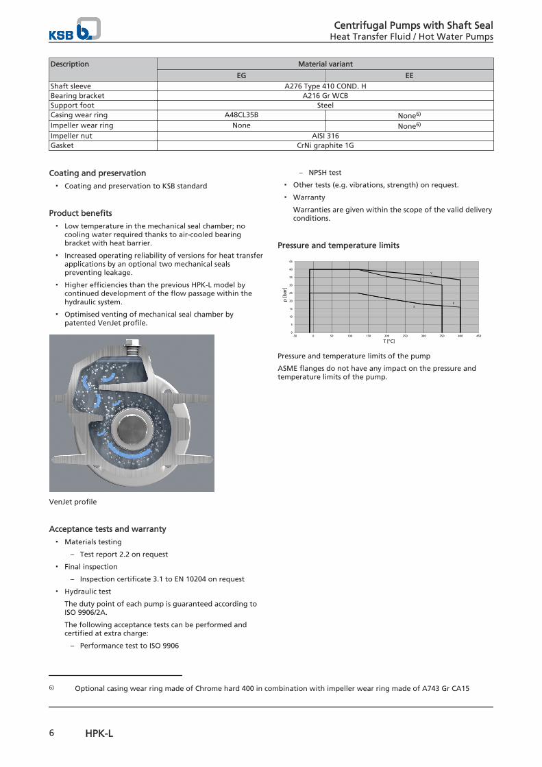
Pressure and temperature limits
0
5
10
15
20
25
30
35
40
45
-50 0 50 100 150 200 250 300 350 400 450
p [b
ar]
T [°C]
E
Y
Z
S
Pressure and temperature limits of the pump
ASME flanges do not have any impact on the pressure andtemperature limits of the pump.
6) Optional casing wear ring made of Chrome hard 400 in combination with impeller wear ring made of A743 Gr CA15
Centrifugal Pumps with Shaft SealHeat Transfer Fluid / Hot Water Pumps
6 HPK-L
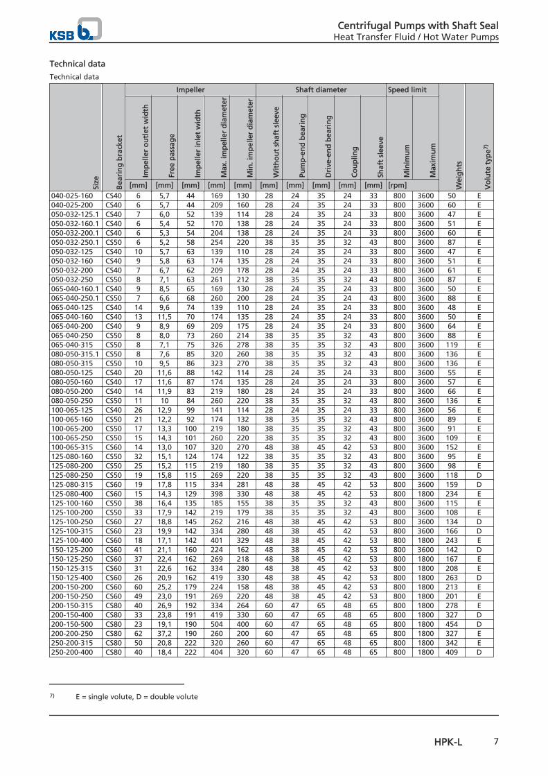
Technical data
Technical data
Size
Bea
rin
g b
rack
et
Impeller Shaft diameter Speed limit
Wei
gh
ts
Vo
lute
typ
e7)
Imp
elle
r o
utl
et w
idth
Free
pas
sag
e
Imp
elle
r in
let
wid
th
Max
. im
pel
ler
dia
met
er
Min
. im
pel
ler
dia
met
er
Wit
ho
ut
shaf
t sl
eeve
Pum
p-e
nd
bea
rin
g
Dri
ve-e
nd
bea
rin
g
Co
up
ling
Shaf
t sl
eeve
Min
imu
m
Max
imu
m
[mm] [mm] [mm] [mm] [mm] [mm] [mm] [mm] [mm] [mm] [rpm]040-025-160 CS40 6 5,7 44 169 130 28 24 35 24 33 800 3600 50 E040-025-200 CS40 6 5,7 44 209 160 28 24 35 24 33 800 3600 60 E050-032-125.1 CS40 7 6,0 52 139 114 28 24 35 24 33 800 3600 47 E050-032-160.1 CS40 6 5,4 52 170 138 28 24 35 24 33 800 3600 51 E050-032-200.1 CS40 6 5,3 54 204 138 28 24 35 24 33 800 3600 60 E050-032-250.1 CS50 6 5,2 58 254 220 38 35 35 32 43 800 3600 87 E050-032-125 CS40 10 5,7 63 139 110 28 24 35 24 33 800 3600 47 E050-032-160 CS40 9 5,8 63 174 135 28 24 35 24 33 800 3600 51 E050-032-200 CS40 7 6,7 62 209 178 28 24 35 24 33 800 3600 61 E050-032-250 CS50 8 7,1 63 261 212 38 35 35 32 43 800 3600 87 E065-040-160.1 CS40 9 8,5 65 169 130 28 24 35 24 33 800 3600 50 E065-040-250.1 CS50 7 6,6 68 260 200 28 24 35 24 43 800 3600 88 E065-040-125 CS40 14 9,6 74 139 110 28 24 35 24 33 800 3600 48 E065-040-160 CS40 13 11,5 70 174 135 28 24 35 24 33 800 3600 50 E065-040-200 CS40 9 8,9 69 209 175 28 24 35 24 33 800 3600 64 E065-040-250 CS50 8 8,0 73 260 214 38 35 35 32 43 800 3600 88 E065-040-315 CS50 8 7,1 75 326 278 38 35 35 32 43 800 3600 119 E080-050-315.1 CS50 8 7,6 85 320 260 38 35 35 32 43 800 3600 136 E080-050-315 CS50 10 9,5 86 323 270 38 35 35 32 43 800 3600 136 E080-050-125 CS40 20 11,6 88 142 114 28 24 35 24 33 800 3600 55 E080-050-160 CS40 17 11,6 87 174 135 28 24 35 24 33 800 3600 57 E080-050-200 CS40 14 11,9 83 219 180 28 24 35 24 33 800 3600 66 E080-050-250 CS50 11 10 84 260 220 38 35 35 32 43 800 3600 136 E100-065-125 CS40 26 12,9 99 141 114 28 24 35 24 33 800 3600 56 E100-065-160 CS50 21 12,2 92 174 132 38 35 35 32 43 800 3600 89 E100-065-200 CS50 17 13,3 100 219 180 38 35 35 32 43 800 3600 91 E100-065-250 CS50 15 14,3 101 260 220 38 35 35 32 43 800 3600 109 E100-065-315 CS60 14 13,0 107 320 270 48 38 45 42 53 800 3600 152 E125-080-160 CS50 32 15,1 124 174 122 38 35 35 32 43 800 3600 95 E125-080-200 CS50 25 15,2 115 219 180 38 35 35 32 43 800 3600 98 E125-080-250 CS50 19 15,8 115 269 220 38 35 35 32 43 800 3600 118 D125-080-315 CS60 19 17,8 115 334 281 48 38 45 42 53 800 3600 159 D125-080-400 CS60 15 14,3 129 398 330 48 38 45 42 53 800 1800 234 E125-100-160 CS50 38 16,4 135 185 155 38 35 35 32 43 800 3600 115 E125-100-200 CS50 33 17,9 142 219 179 38 35 35 32 43 800 3600 108 E125-100-250 CS60 27 18,8 145 262 216 48 38 45 42 53 800 3600 134 D125-100-315 CS60 23 19,9 142 334 280 48 38 45 42 53 800 3600 166 D125-100-400 CS60 18 17,1 142 401 329 48 38 45 42 53 800 1800 243 E150-125-200 CS60 41 21,1 160 224 162 48 38 45 42 53 800 3600 142 D150-125-250 CS60 37 22,4 162 269 218 48 38 45 42 53 800 1800 167 E150-125-315 CS60 31 22,6 162 334 280 48 38 45 42 53 800 1800 208 E150-125-400 CS60 26 20,9 162 419 330 48 38 45 42 53 800 1800 263 D200-150-200 CS60 60 25,2 179 224 158 48 38 45 42 53 800 1800 213 E200-150-250 CS60 49 23,0 191 269 220 48 38 45 42 53 800 1800 201 E200-150-315 CS80 40 26,9 192 334 264 60 47 65 48 65 800 1800 278 E200-150-400 CS80 33 23,8 191 419 330 60 47 65 48 65 800 1800 327 D200-150-500 CS80 23 19,1 190 504 400 60 47 65 48 65 800 1800 454 D200-200-250 CS80 62 37,2 190 260 200 60 47 65 48 65 800 1800 327 E250-200-315 CS80 50 20,8 222 320 260 60 47 65 48 65 800 1800 342 E250-200-400 CS80 40 18,4 222 404 320 60 47 65 48 65 800 1800 409 D
7) E = single volute, D = double volute
Centrifugal Pumps with Shaft SealHeat Transfer Fluid / Hot Water Pumps
HPK-L 7
Size
Bea
rin
g b
rack
et
Impeller Shaft diameter Speed limit
Wei
gh
ts
Vo
lute
typ
e7)
Imp
elle
r o
utl
et w
idth
Free
pas
sag
e
Imp
elle
r in
let
wid
th
Max
. im
pel
ler
dia
met
er
Min
. im
pel
ler
dia
met
er
Wit
ho
ut
shaf
t sl
eeve
Pum
p-e
nd
bea
rin
g
Dri
ve-e
nd
bea
rin
g
Co
up
ling
Shaf
t sl
eeve
Min
imu
m
Max
imu
m
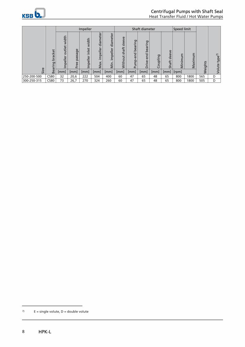
[mm] [mm] [mm] [mm] [mm] [mm] [mm] [mm] [mm] [mm] [rpm]250-200-500 CS80 32 20,6 222 504 400 60 47 65 48 65 800 1800 565 D300-250-315 CS80 73 26,7 270 324 260 60 47 65 48 65 800 1800 505 D
7) E = single volute, D = double volute
Centrifugal Pumps with Shaft SealHeat Transfer Fluid / Hot Water Pumps
8 HPK-L
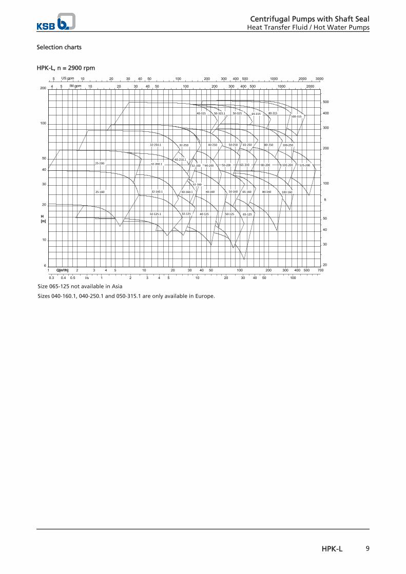
Selection charts
HPK-L, n = 2900 rpm
H[m]
Q[m³/h]1 2 3 4 5 10 20 30 40 50 100 200 300 400 500 700Q[m³/h]
5 10 20 30 40 50 100 200 300 400 500 1000 2000 3000US.gpm
4 5 10 20 30 40 50 100 200 300 400 500 1000 2000IM.gpm
10
20
30
40
50
100
200
6
H[m]
20
30
40
50
100
200
300
400
500
ft
0.3 0.4 0.5 1 2 3 4 5 10 20 30 40 50 100l/s
100-315
125-200
80-31565-31550-315
100-250
100-200
80-250
80-200
65-250
65-200
100-16080-16065-160
65-125
50-250
50-200
50-160
50-125
50-315.140-315
40-250
40-200
40-160
40-125
32-200
40-250.1
32-250
32-160
40-160.1
32-125
32-250.1
32-200.1
32-160.1
32-125.1
25-200
25-160
Size 065-125 not available in Asia
Sizes 040-160.1, 040-250.1 and 050-315.1 are only available in Europe.
Centrifugal Pumps with Shaft SealHeat Transfer Fluid / Hot Water Pumps
HPK-L 9
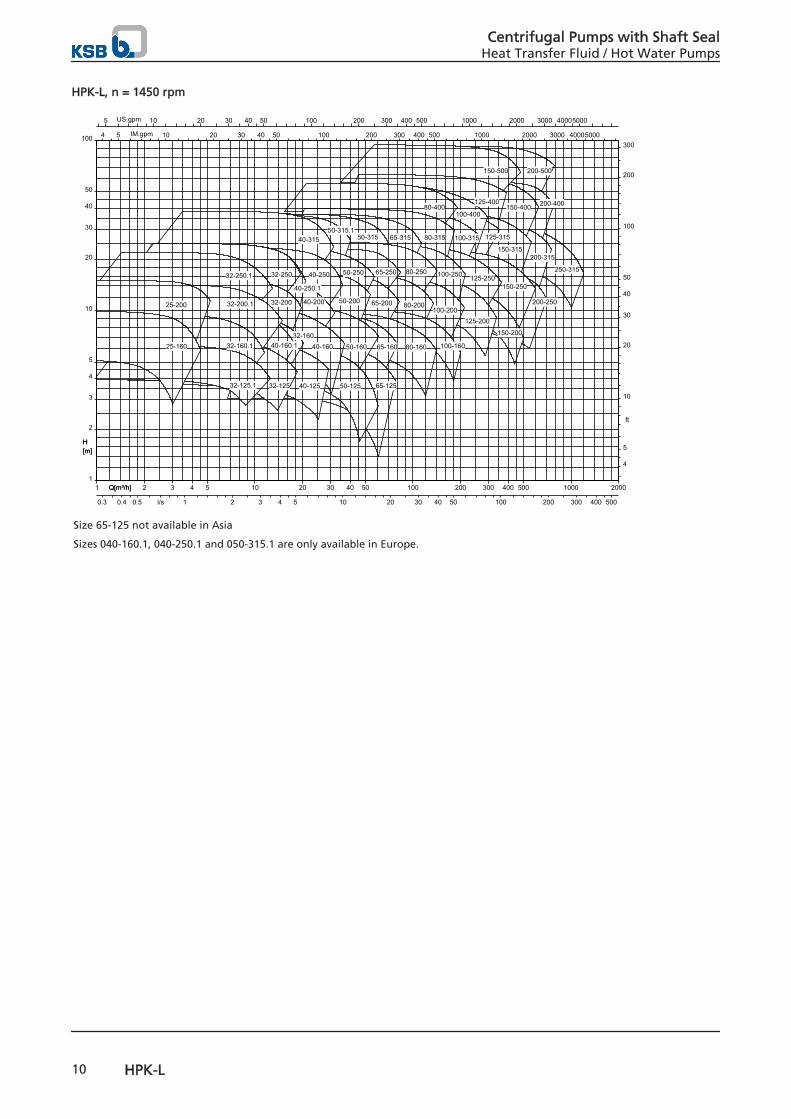
HPK-L, n = 1450 rpm
H[m]
Q[m³/h]1 2 3 4 5 10 20 30 40 50 100 200 300 400 500 1000 2000Q[m³/h]
5 10 20 30 40 50 100 200 300 400 500 1000 2000 3000 40005000US.gpm
4 5 10 20 30 40 50 100 200 300 400 500 1000 2000 3000 40005000IM.gpm
1
2
3
4
5
10
20
30
40
50
100
H[m]
4
5
10
20
30
40
50
100
200
300
ft
0.3 0.4 0.5 1 2 3 4 5 10 20 30 40 50 100 200 300 400 500l/s
200-500
250-315
200-400
200-315
150-400
150-500
125-400
150-315
125-315
100-400
200-250
150-250
150-200
100-315
125-250
125-200
80-400
80-315
100-250
100-200
65-31550-315
80-250
80-200
100-160
65-250
50-315.1
65-200
80-16065-160
65-125
50-250
50-200
50-160
50-125
40-315
40-250
40-200
40-250.1
40-160
40-125
32-250
32-200
32-16040-160.1
32-125
32-250.1
32-200.1
32-160.1
32-125.1
25-200
25-160
Size 65-125 not available in Asia
Sizes 040-160.1, 040-250.1 and 050-315.1 are only available in Europe.
Centrifugal Pumps with Shaft SealHeat Transfer Fluid / Hot Water Pumps
10 HPK-L
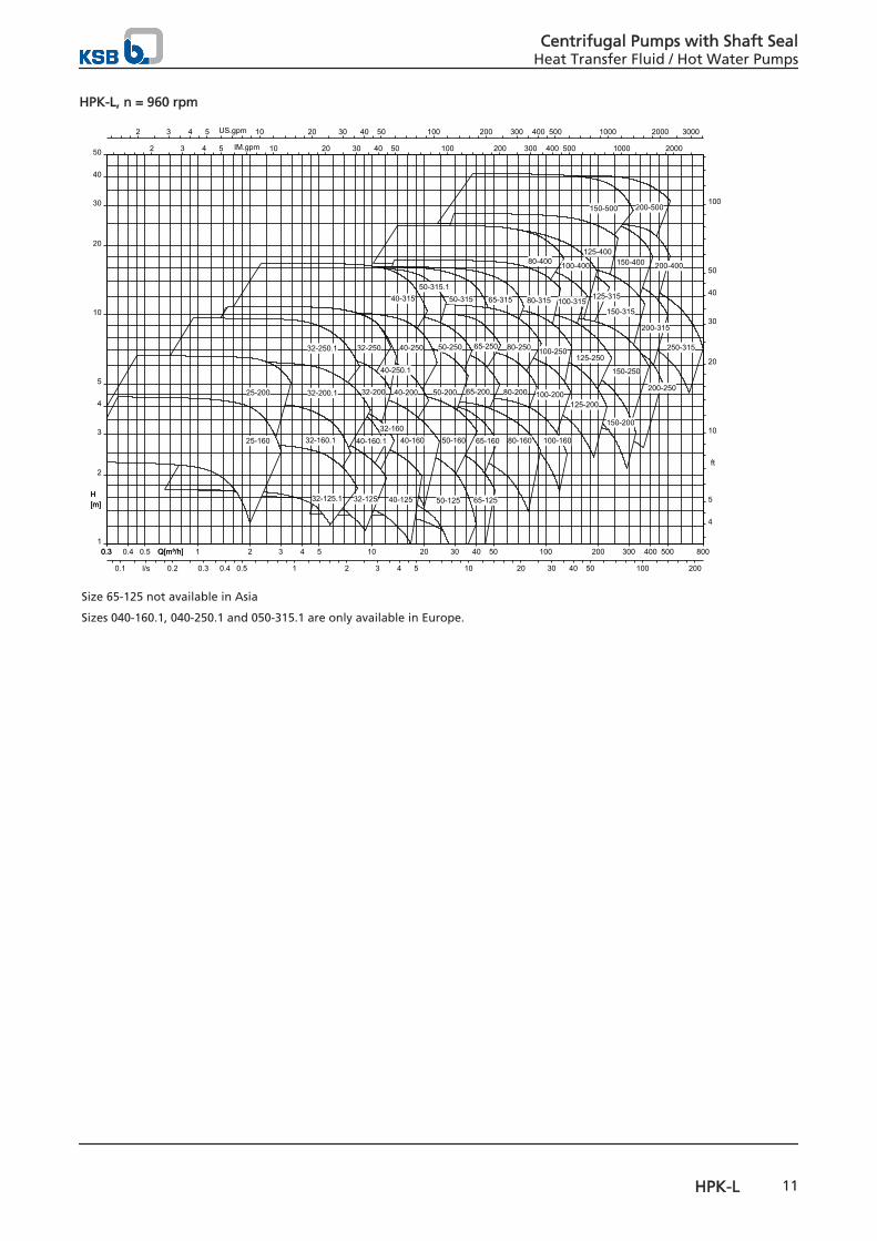
HPK-L, n = 960 rpm
H[m]
Q[m³/h]0.3 0.4 0.5 1 2 3 4 5 10 20 30 40 50 100 200 300 400 5000.3 800Q[m³/h]
2 3 4 5 10 20 30 40 50 100 200 300 400 500 1000 2000 3000US.gpm
2 3 4 5 10 20 30 40 50 100 200 300 400 500 1000 2000IM.gpm
1
2
3
4
5
10
20
30
40
50
H[m]
4
5
10
20
30
40
50
100
ft
0.1 0.2 0.3 0.4 0.5 1 2 3 4 5 10 20 30 40 50 100 200l/s
200-500
250-315
200-400
200-315
150-400
150-500
125-400
150-315
125-315
100-400
200-250
150-250
150-200
100-315
125-250
125-200
80-400
80-315
100-250
100-200
65-31550-315
80-250
80-200
100-160
65-250
50-315.1
65-200
80-16065-160
65-125
50-250
50-200
50-160
50-125
40-315
40-250
40-200
40-250.1
40-160
40-125
32-250
32-200
32-16040-160.1
32-125
32-250.1
32-200.1
32-160.1
32-125.1
25-200
25-160
Size 65-125 not available in Asia
Sizes 040-160.1, 040-250.1 and 050-315.1 are only available in Europe.
Centrifugal Pumps with Shaft SealHeat Transfer Fluid / Hot Water Pumps
HPK-L 11
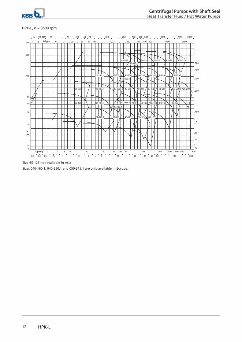
HPK-L, n = 3500 rpm
H[m]
Q[m³/h]1 2 3 4 5 10 20 30 40 50 100 200 300 400 500 800Q[m³/h]
5 10 20 30 40 50 100 200 300 400 500 1000 2000 3000US.gpm
4 5 10 20 30 40 50 100 200 300 400 500 1000 2000IM.gpm
10
20
30
40
50
100
200
300
9
H[m]
30
40
50
100
200
300
400
500
ft
0.3 0.4 0.5 1 2 3 4 5 10 20 30 40 50 100 200l/s
100-315
125-200
80-31565-31550-315
100-250
100-200
80-250
80-200
65-250
65-200
100-16080-16065-160
65-125
50-250
50-200
50-160
50-125
50-315.140-315
40-250
40-200
40-160
40-125
40-250.1
32-250
32-200
32-160
40-160.1
32-125
32-250.1
32-200.1
32-160.1
32-125.1
25-200
25-160
Size 65-125 not available in Asia
Sizes 040-160.1, 040-250.1 and 050-315.1 are only available in Europe.
Centrifugal Pumps with Shaft SealHeat Transfer Fluid / Hot Water Pumps
12 HPK-L
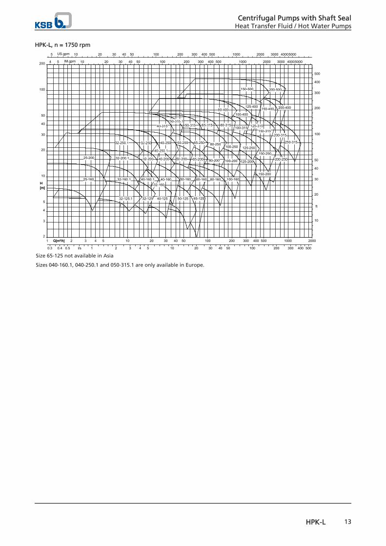
HPK-L, n = 1750 rpm
H[m]
Q[m³/h]1 2 3 4 5 10 20 30 40 50 100 200 300 400 500 1000 2000Q[m³/h]
5 10 20 30 40 50 100 200 300 400 500 1000 2000 3000 40005000US.gpm
4 5 10 20 30 40 50 100 200 300 400 500 1000 2000 3000 40005000IM.gpm
2
3
4
5
10
20
30
40
50
100
200
H[m]
10
20
30
40
50
100
200
300
400
500
ft
0.3 0.4 0.5 1 2 3 4 5 10 20 30 40 50 100 200 300 400 500l/s
200-500
250-315
200-400
200-315
150-400
150-500
125-400
150-315125-315
100-400
200-250
150-250
150-200
100-315
125-250
125-200
80-400
80-315
100-250
100-200
65-31550-315
80-250
80-200
100-160
65-250
50-315.1
65-200
80-16065-160
65-125
50-250
50-200
50-160
50-125
40-315
40-250
40-200
40-250.1
40-160
40-125
32-250
32-200
32-16040-160.1
32-125
32-250.1
32-200.1
32-160.1
32-125.1
25-200
25-160
Size 65-125 not available in Asia
Sizes 040-160.1, 040-250.1 and 050-315.1 are only available in Europe.
Centrifugal Pumps with Shaft SealHeat Transfer Fluid / Hot Water Pumps
HPK-L 13
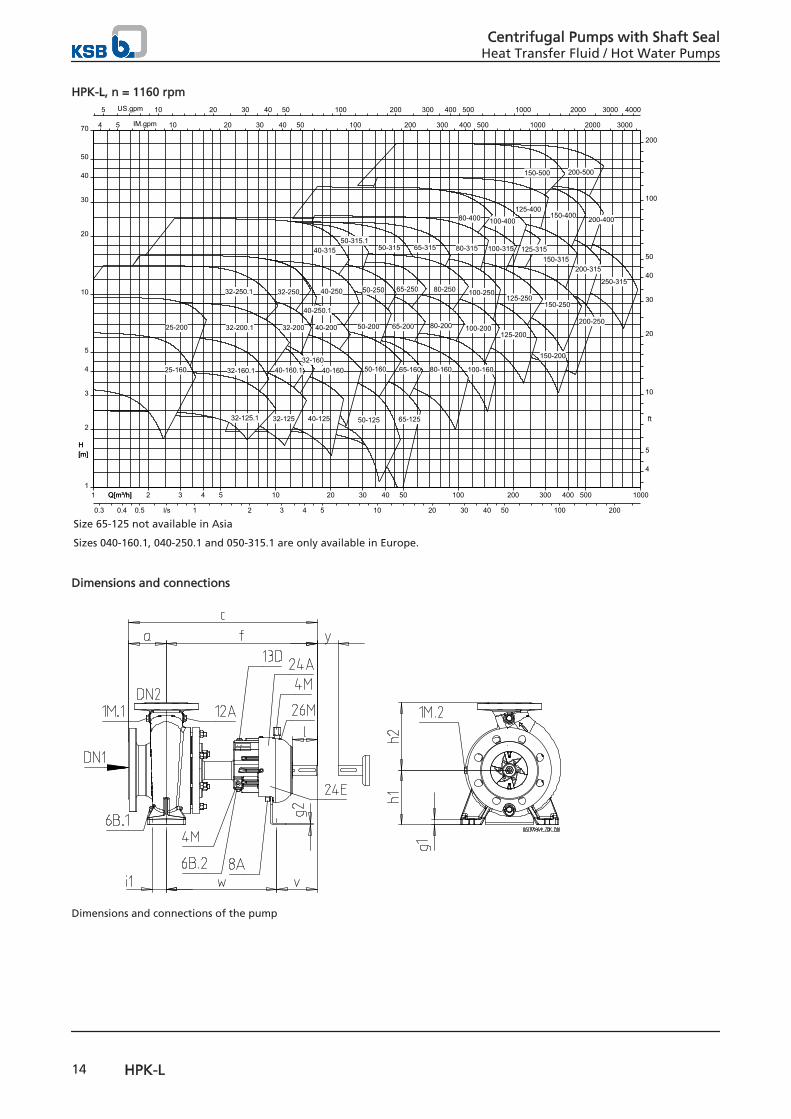
HPK-L, n = 1160 rpm
H[m]
Q[m³/h]1 2 3 4 5 10 20 30 40 50 100 200 300 400 500 1000Q[m³/h]
5 10 20 30 40 50 100 200 300 400 500 1000 2000 3000 4000US.gpm
4 5 10 20 30 40 50 100 200 300 400 500 1000 2000 3000IM.gpm
1
2
3
4
5
10
20
30
40
50
70
H[m]
4
5
10
20
30
40
50
100
200
ft
0.3 0.4 0.5 1 2 3 4 5 10 20 30 40 50 100 200l/s
200-500
250-315
200-400
200-315
150-400
150-500
125-400
150-315125-315
100-400
200-250
150-250
150-200
100-315
125-250
125-200
80-400
80-315
100-250
100-200
65-31550-315
80-250
80-200
100-160
65-250
50-315.1
65-200
80-16065-160
65-125
50-250
50-200
50-160
50-125
40-315
40-250
40-200
40-250.1
40-160
40-125
32-250
32-200
32-16040-160.1
32-125
32-250.1
32-200.1
32-160.1
32-125.1
25-200
25-160
Size 65-125 not available in Asia
Sizes 040-160.1, 040-250.1 and 050-315.1 are only available in Europe.
Dimensions and connections
Dimensions and connections of the pump
Centrifugal Pumps with Shaft SealHeat Transfer Fluid / Hot Water Pumps
14 HPK-L
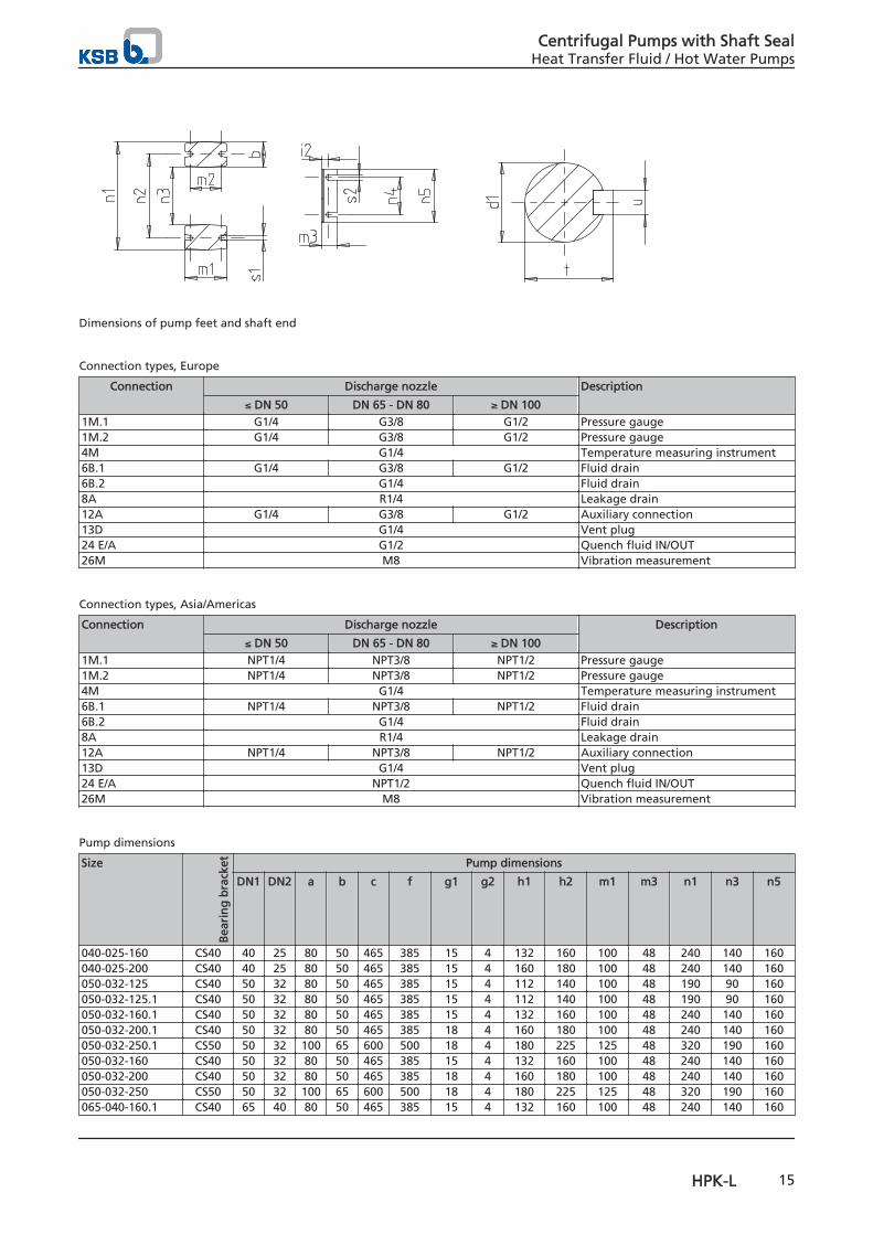
Dimensions of pump feet and shaft end
Connection types, Europe
Connection Discharge nozzle Description
≤ DN 50 DN 65 - DN 80 ≥ DN 1001M.1 G1/4 G3/8 G1/2 Pressure gauge1M.2 G1/4 G3/8 G1/2 Pressure gauge4M G1/4 Temperature measuring instrument6B.1 G1/4 G3/8 G1/2 Fluid drain6B.2 G1/4 Fluid drain8A R1/4 Leakage drain12A G1/4 G3/8 G1/2 Auxiliary connection13D G1/4 Vent plug24 E/A G1/2 Quench fluid IN/OUT26M M8 Vibration measurement
Connection types, Asia/Americas
Connection Discharge nozzle Description
≤ DN 50 DN 65 - DN 80 ≥ DN 1001M.1 NPT1/4 NPT3/8 NPT1/2 Pressure gauge1M.2 NPT1/4 NPT3/8 NPT1/2 Pressure gauge4M G1/4 Temperature measuring instrument6B.1 NPT1/4 NPT3/8 NPT1/2 Fluid drain6B.2 G1/4 Fluid drain8A R1/4 Leakage drain12A NPT1/4 NPT3/8 NPT1/2 Auxiliary connection13D G1/4 Vent plug24 E/A NPT1/2 Quench fluid IN/OUT26M M8 Vibration measurement
Pump dimensions
Size
Bea
rin
g b
rack
et Pump dimensions
DN1 DN2 a b c f g1 g2 h1 h2 m1 m3 n1 n3 n5
040-025-160 CS40 40 25 80 50 465 385 15 4 132 160 100 48 240 140 160040-025-200 CS40 40 25 80 50 465 385 15 4 160 180 100 48 240 140 160050-032-125 CS40 50 32 80 50 465 385 15 4 112 140 100 48 190 90 160050-032-125.1 CS40 50 32 80 50 465 385 15 4 112 140 100 48 190 90 160050-032-160.1 CS40 50 32 80 50 465 385 15 4 132 160 100 48 240 140 160050-032-200.1 CS40 50 32 80 50 465 385 18 4 160 180 100 48 240 140 160050-032-250.1 CS50 50 32 100 65 600 500 18 4 180 225 125 48 320 190 160050-032-160 CS40 50 32 80 50 465 385 15 4 132 160 100 48 240 140 160050-032-200 CS40 50 32 80 50 465 385 18 4 160 180 100 48 240 140 160050-032-250 CS50 50 32 100 65 600 500 18 4 180 225 125 48 320 190 160065-040-160.1 CS40 65 40 80 50 465 385 15 4 132 160 100 48 240 140 160
Centrifugal Pumps with Shaft SealHeat Transfer Fluid / Hot Water Pumps
HPK-L 15
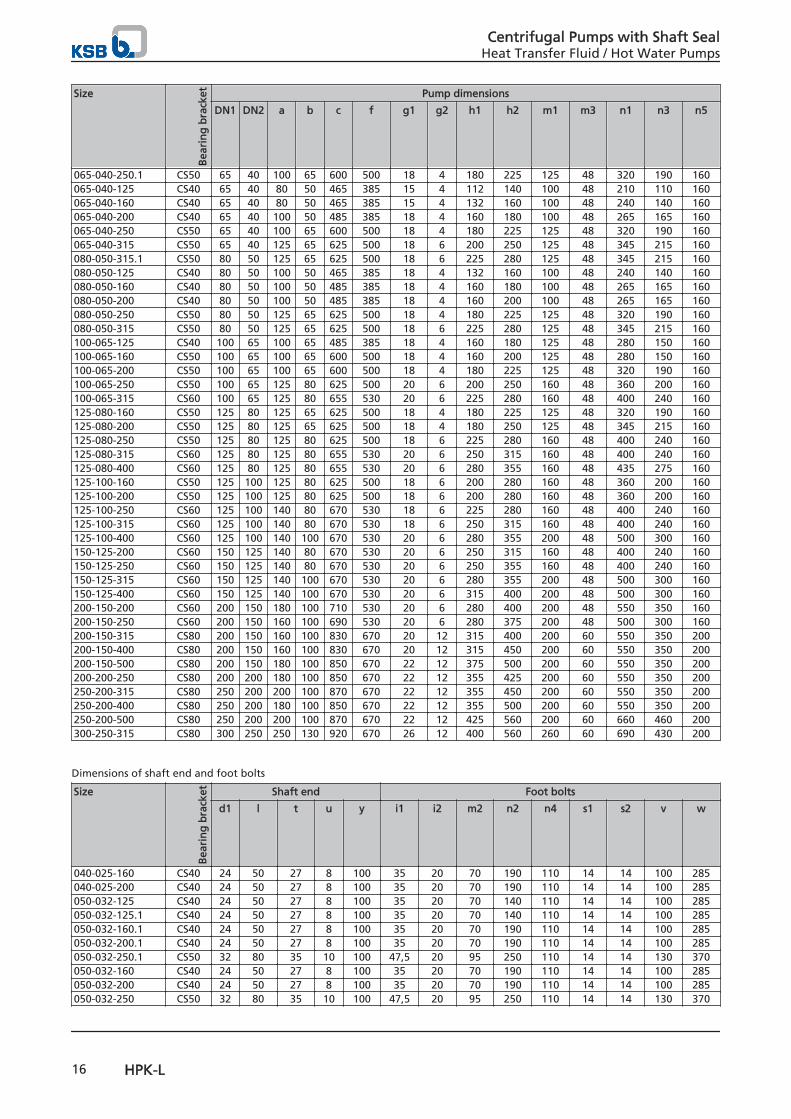
Size
Bea
rin
g b
rack
et Pump dimensions
DN1 DN2 a b c f g1 g2 h1 h2 m1 m3 n1 n3 n5
065-040-250.1 CS50 65 40 100 65 600 500 18 4 180 225 125 48 320 190 160065-040-125 CS40 65 40 80 50 465 385 15 4 112 140 100 48 210 110 160065-040-160 CS40 65 40 80 50 465 385 15 4 132 160 100 48 240 140 160065-040-200 CS40 65 40 100 50 485 385 18 4 160 180 100 48 265 165 160065-040-250 CS50 65 40 100 65 600 500 18 4 180 225 125 48 320 190 160065-040-315 CS50 65 40 125 65 625 500 18 6 200 250 125 48 345 215 160080-050-315.1 CS50 80 50 125 65 625 500 18 6 225 280 125 48 345 215 160080-050-125 CS40 80 50 100 50 465 385 18 4 132 160 100 48 240 140 160080-050-160 CS40 80 50 100 50 485 385 18 4 160 180 100 48 265 165 160080-050-200 CS40 80 50 100 50 485 385 18 4 160 200 100 48 265 165 160080-050-250 CS50 80 50 125 65 625 500 18 4 180 225 125 48 320 190 160080-050-315 CS50 80 50 125 65 625 500 18 6 225 280 125 48 345 215 160100-065-125 CS40 100 65 100 65 485 385 18 4 160 180 125 48 280 150 160100-065-160 CS50 100 65 100 65 600 500 18 4 160 200 125 48 280 150 160100-065-200 CS50 100 65 100 65 600 500 18 4 180 225 125 48 320 190 160100-065-250 CS50 100 65 125 80 625 500 20 6 200 250 160 48 360 200 160100-065-315 CS60 100 65 125 80 655 530 20 6 225 280 160 48 400 240 160125-080-160 CS50 125 80 125 65 625 500 18 4 180 225 125 48 320 190 160125-080-200 CS50 125 80 125 65 625 500 18 4 180 250 125 48 345 215 160125-080-250 CS50 125 80 125 80 625 500 18 6 225 280 160 48 400 240 160125-080-315 CS60 125 80 125 80 655 530 20 6 250 315 160 48 400 240 160125-080-400 CS60 125 80 125 80 655 530 20 6 280 355 160 48 435 275 160125-100-160 CS50 125 100 125 80 625 500 18 6 200 280 160 48 360 200 160125-100-200 CS50 125 100 125 80 625 500 18 6 200 280 160 48 360 200 160125-100-250 CS60 125 100 140 80 670 530 18 6 225 280 160 48 400 240 160125-100-315 CS60 125 100 140 80 670 530 18 6 250 315 160 48 400 240 160125-100-400 CS60 125 100 140 100 670 530 20 6 280 355 200 48 500 300 160150-125-200 CS60 150 125 140 80 670 530 20 6 250 315 160 48 400 240 160150-125-250 CS60 150 125 140 80 670 530 20 6 250 355 160 48 400 240 160150-125-315 CS60 150 125 140 100 670 530 20 6 280 355 200 48 500 300 160150-125-400 CS60 150 125 140 100 670 530 20 6 315 400 200 48 500 300 160200-150-200 CS60 200 150 180 100 710 530 20 6 280 400 200 48 550 350 160200-150-250 CS60 200 150 160 100 690 530 20 6 280 375 200 48 500 300 160200-150-315 CS80 200 150 160 100 830 670 20 12 315 400 200 60 550 350 200200-150-400 CS80 200 150 160 100 830 670 20 12 315 450 200 60 550 350 200200-150-500 CS80 200 150 180 100 850 670 22 12 375 500 200 60 550 350 200200-200-250 CS80 200 200 180 100 850 670 22 12 355 425 200 60 550 350 200250-200-315 CS80 250 200 200 100 870 670 22 12 355 450 200 60 550 350 200250-200-400 CS80 250 200 180 100 850 670 22 12 355 500 200 60 550 350 200250-200-500 CS80 250 200 200 100 870 670 22 12 425 560 200 60 660 460 200300-250-315 CS80 300 250 250 130 920 670 26 12 400 560 260 60 690 430 200
Dimensions of shaft end and foot bolts
Size
Bea
rin
g b
rack
et Shaft end Foot bolts
d1 l t u y i1 i2 m2 n2 n4 s1 s2 v w
040-025-160 CS40 24 50 27 8 100 35 20 70 190 110 14 14 100 285040-025-200 CS40 24 50 27 8 100 35 20 70 190 110 14 14 100 285050-032-125 CS40 24 50 27 8 100 35 20 70 140 110 14 14 100 285050-032-125.1 CS40 24 50 27 8 100 35 20 70 140 110 14 14 100 285050-032-160.1 CS40 24 50 27 8 100 35 20 70 190 110 14 14 100 285050-032-200.1 CS40 24 50 27 8 100 35 20 70 190 110 14 14 100 285050-032-250.1 CS50 32 80 35 10 100 47,5 20 95 250 110 14 14 130 370050-032-160 CS40 24 50 27 8 100 35 20 70 190 110 14 14 100 285050-032-200 CS40 24 50 27 8 100 35 20 70 190 110 14 14 100 285050-032-250 CS50 32 80 35 10 100 47,5 20 95 250 110 14 14 130 370
Centrifugal Pumps with Shaft SealHeat Transfer Fluid / Hot Water Pumps
16 HPK-L
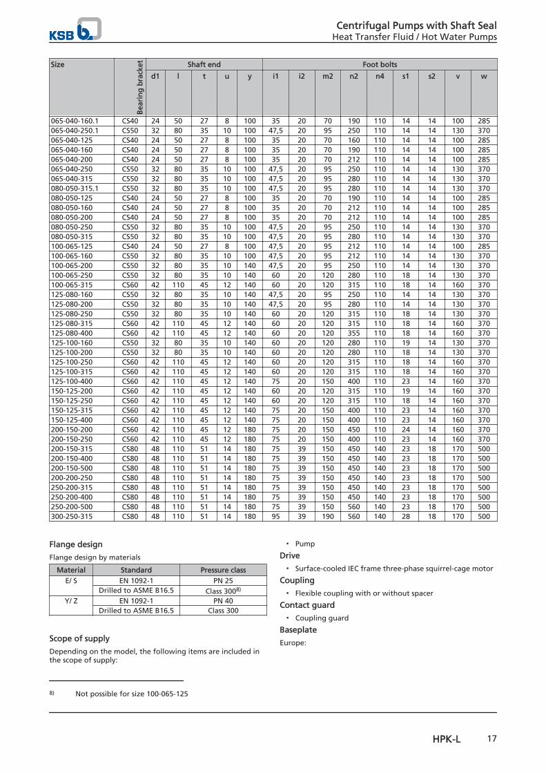
Size
Bea
rin
g b
rack
et Shaft end Foot bolts
d1 l t u y i1 i2 m2 n2 n4 s1 s2 v w
065-040-160.1 CS40 24 50 27 8 100 35 20 70 190 110 14 14 100 285065-040-250.1 CS50 32 80 35 10 100 47,5 20 95 250 110 14 14 130 370065-040-125 CS40 24 50 27 8 100 35 20 70 160 110 14 14 100 285065-040-160 CS40 24 50 27 8 100 35 20 70 190 110 14 14 100 285065-040-200 CS40 24 50 27 8 100 35 20 70 212 110 14 14 100 285065-040-250 CS50 32 80 35 10 100 47,5 20 95 250 110 14 14 130 370065-040-315 CS50 32 80 35 10 100 47,5 20 95 280 110 14 14 130 370080-050-315.1 CS50 32 80 35 10 100 47,5 20 95 280 110 14 14 130 370080-050-125 CS40 24 50 27 8 100 35 20 70 190 110 14 14 100 285080-050-160 CS40 24 50 27 8 100 35 20 70 212 110 14 14 100 285080-050-200 CS40 24 50 27 8 100 35 20 70 212 110 14 14 100 285080-050-250 CS50 32 80 35 10 100 47,5 20 95 250 110 14 14 130 370080-050-315 CS50 32 80 35 10 100 47,5 20 95 280 110 14 14 130 370100-065-125 CS40 24 50 27 8 100 47,5 20 95 212 110 14 14 100 285100-065-160 CS50 32 80 35 10 100 47,5 20 95 212 110 14 14 130 370100-065-200 CS50 32 80 35 10 140 47,5 20 95 250 110 14 14 130 370100-065-250 CS50 32 80 35 10 140 60 20 120 280 110 18 14 130 370100-065-315 CS60 42 110 45 12 140 60 20 120 315 110 18 14 160 370125-080-160 CS50 32 80 35 10 140 47,5 20 95 250 110 14 14 130 370125-080-200 CS50 32 80 35 10 140 47,5 20 95 280 110 14 14 130 370125-080-250 CS50 32 80 35 10 140 60 20 120 315 110 18 14 130 370125-080-315 CS60 42 110 45 12 140 60 20 120 315 110 18 14 160 370125-080-400 CS60 42 110 45 12 140 60 20 120 355 110 18 14 160 370125-100-160 CS50 32 80 35 10 140 60 20 120 280 110 19 14 130 370125-100-200 CS50 32 80 35 10 140 60 20 120 280 110 18 14 130 370125-100-250 CS60 42 110 45 12 140 60 20 120 315 110 18 14 160 370125-100-315 CS60 42 110 45 12 140 60 20 120 315 110 18 14 160 370125-100-400 CS60 42 110 45 12 140 75 20 150 400 110 23 14 160 370150-125-200 CS60 42 110 45 12 140 60 20 120 315 110 19 14 160 370150-125-250 CS60 42 110 45 12 140 60 20 120 315 110 18 14 160 370150-125-315 CS60 42 110 45 12 140 75 20 150 400 110 23 14 160 370150-125-400 CS60 42 110 45 12 140 75 20 150 400 110 23 14 160 370200-150-200 CS60 42 110 45 12 180 75 20 150 450 110 24 14 160 370200-150-250 CS60 42 110 45 12 180 75 20 150 400 110 23 14 160 370200-150-315 CS80 48 110 51 14 180 75 39 150 450 140 23 18 170 500200-150-400 CS80 48 110 51 14 180 75 39 150 450 140 23 18 170 500200-150-500 CS80 48 110 51 14 180 75 39 150 450 140 23 18 170 500200-200-250 CS80 48 110 51 14 180 75 39 150 450 140 23 18 170 500250-200-315 CS80 48 110 51 14 180 75 39 150 450 140 23 18 170 500250-200-400 CS80 48 110 51 14 180 75 39 150 450 140 23 18 170 500250-200-500 CS80 48 110 51 14 180 75 39 150 560 140 23 18 170 500300-250-315 CS80 48 110 51 14 180 95 39 190 560 140 28 18 170 500
Flange design
Flange design by materials
Material Standard Pressure classE/ S EN 1092-1 PN 25
Drilled to ASME B16.5 Class 3008)
Y/ Z EN 1092-1 PN 40Drilled to ASME B16.5 Class 300
Scope of supply
Depending on the model, the following items are included inthe scope of supply:
▪ Pump
Drive
▪ Surface-cooled IEC frame three-phase squirrel-cage motor
Coupling
▪ Flexible coupling with or without spacer
Contact guard
▪ Coupling guard
Baseplate
Europe:
8) Not possible for size 100-065-125
Centrifugal Pumps with Shaft SealHeat Transfer Fluid / Hot Water Pumps
HPK-L 17
▪ Baseplate (to ISO 3661), cast or welded, for pump andmotor, in torsion-resistant design
▪ Channel section steel or folded steel plate
Asia/Americas:
▪ Baseplate to local KSB standard
Special accessories
▪ As required
Centrifugal Pumps with Shaft SealHeat Transfer Fluid / Hot Water Pumps
18 HPK-L
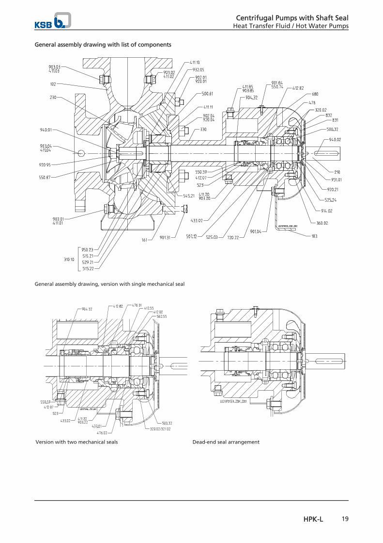
General assembly drawing with list of components
General assembly drawing, version with single mechanical seal
Version with two mechanical seals Dead-end seal arrangement
Centrifugal Pumps with Shaft SealHeat Transfer Fluid / Hot Water Pumps
HPK-L 19
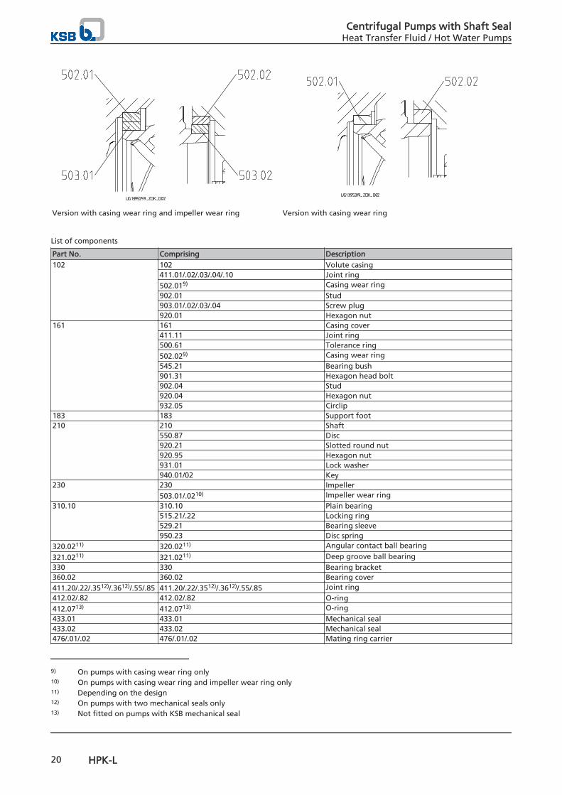
Version with casing wear ring and impeller wear ring Version with casing wear ring
List of components
Part No. Comprising Description102 102 Volute casing
411.01/.02/.03/.04/.10 Joint ring502.019) Casing wear ring902.01 Stud903.01/.02/.03/.04 Screw plug920.01 Hexagon nut
161 161 Casing cover411.11 Joint ring500.61 Tolerance ring502.029) Casing wear ring545.21 Bearing bush901.31 Hexagon head bolt902.04 Stud920.04 Hexagon nut932.05 Circlip
183 183 Support foot210 210 Shaft
550.87 Disc920.21 Slotted round nut920.95 Hexagon nut931.01 Lock washer940.01/02 Key
230 230 Impeller503.01/.0210) Impeller wear ring
310.10 310.10 Plain bearing515.21/.22 Locking ring529.21 Bearing sleeve950.23 Disc spring
320.0211) 320.0211) Angular contact ball bearing
321.0211) 321.0211) Deep groove ball bearing330 330 Bearing bracket360.02 360.02 Bearing cover411.20/.22/.3512)/.3612)/.55/.85 411.20/.22/.3512)/.3612)/.55/.85 Joint ring412.02/.82 412.02/.82 O-ring412.0713) 412.0713) O-ring433.01 433.01 Mechanical seal433.02 433.02 Mechanical seal476/.01/.02 476/.01/.02 Mating ring carrier
9) On pumps with casing wear ring only10) On pumps with casing wear ring and impeller wear ring only11) Depending on the design12) On pumps with two mechanical seals only13) Not fitted on pumps with KSB mechanical seal
Centrifugal Pumps with Shaft SealHeat Transfer Fluid / Hot Water Pumps
20 HPK-L
Part No. Comprising Description500.32 500.32 Nilos ring507.12 507.12 Thrower52313) 52313) Shaft sleeve525.03/.24 525.03/.24 Spacer sleeve550.5913) 550.5913) Support disc550.74 550.74 Disc562.55 562.55 Parallel pin680 680 Guard720.22 720.22 Hexagon nipple720.3512)/.3612) 720.3512)/.3612) Extension831 831 Fan impeller832 832 Fan hood901.04/.84 901.04/.84 Hexagon head bolt902.04 902.04 Stud903.20/.22/.85 903.20/.22/.85 Screw plug904.3213) 904.3213) Grub screw914.02 914.02 Hexagon socket head cap screw920.04 920.04 Hexagon nut
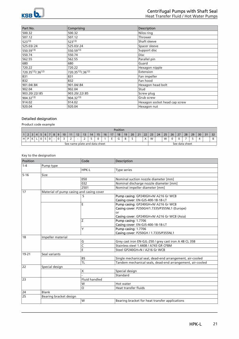
Detailed designation
Product code example
Position
1 2 3 4 5 6 7 8 9 10 11 12 13 14 15 16 17 18 19 20 21 22 23 24 25 26 27 28 29 30 31 32
H P K L 0 5 0 - 0 3 2 - 2 5 0 1 E G B S X W W 0 0 7 5 4 B
See name plate and data sheet See data sheet
Key to the designation
Position Code Description1-4 Pump type
HPK-L Type series
5-16 Size 050 Nominal suction nozzle diameter [mm]
032 Nominal discharge nozzle diameter [mm]2501 Nominal impeller diameter [mm]
17 Material of pump casing and casing cover S Pump casing: GP240GH+N/ A216 Gr WCB
Casing cover: EN-GJS-400-18-18-LT E Pump casing: GP240GH+N/ A216 Gr WCB
Casing cover: P250GH/1.7335/P355NL1 (Europe)orCasing cover: GP240GH+N/ A216 Gr WCB (Asia)
Z Pump casing: 1.7706Casing cover: EN-GJS-400-18-18-LT
Y Pump casing: 1.7706Casing cover: P250GH / 1.7335/P355NL1
18 Impeller material G Grey cast iron EN-GJL-250 / grey cast iron A 48 CL 35B
C Stainless steel 1.4408 / A743 GR CF8ME Steel GP240GH+N / A216 Gr WCB
19-21 Seal variants BS Single mechanical seal, dead-end arrangement, air-cooled
TL Tandem mechanical seals, dead-end arrangement, air-cooled22 Special design
X Special design- Standard
23 Fluid handledW Hot waterO Heat transfer fluids
24 Blank25 Bearing bracket design
W Bearing bracket for heat transfer applications
Centrifugal Pumps with Shaft SealHeat Transfer Fluid / Hot Water Pumps
HPK-L 21
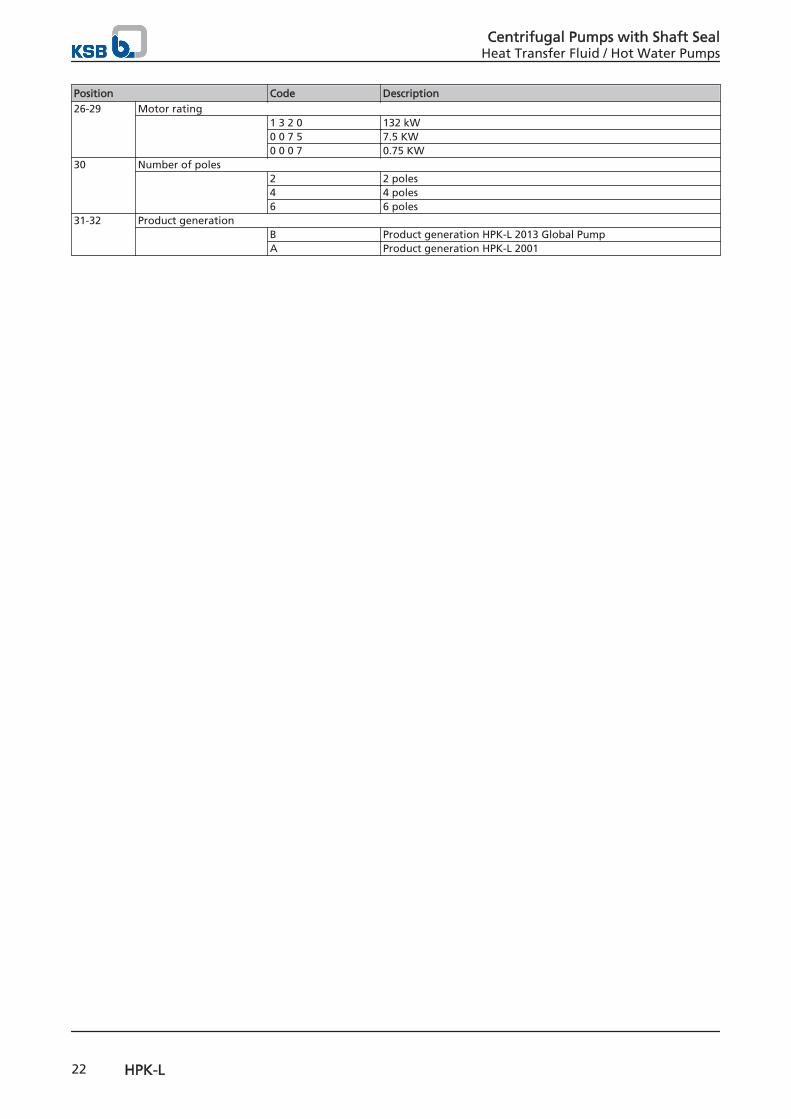
Position Code Description26-29 Motor rating
1 3 2 0 132 kW0 0 7 5 7.5 KW0 0 0 7 0.75 KW
30 Number of poles 2 2 poles
4 4 poles6 6 poles
31-32 Product generation B Product generation HPK-L 2013 Global Pump
A Product generation HPK-L 2001
Centrifugal Pumps with Shaft SealHeat Transfer Fluid / Hot Water Pumps
22 HPK-L


1136
.51/
08-E
N04
.04.
2016
KSB Aktiengesellschaft67225 Frankenthal • Johann-Klein-Str. 9 • 67227 Frankenthal (Deutschland)Tel. +49 6233 86-0 • Fax +49 6233 86-3401www.ksb.de
KSB Pumps LimitedPlot no. E3 & E4, MIDC, Sinnar, (Malegaon) • Nashik 422 113Tel. +91 2551 230252Tel. +91 2551 230253Tel. +91 2551 229700Fax +91 2551 230254 • www.ksb.india.co.in