Embed Size (px)
Citation preview
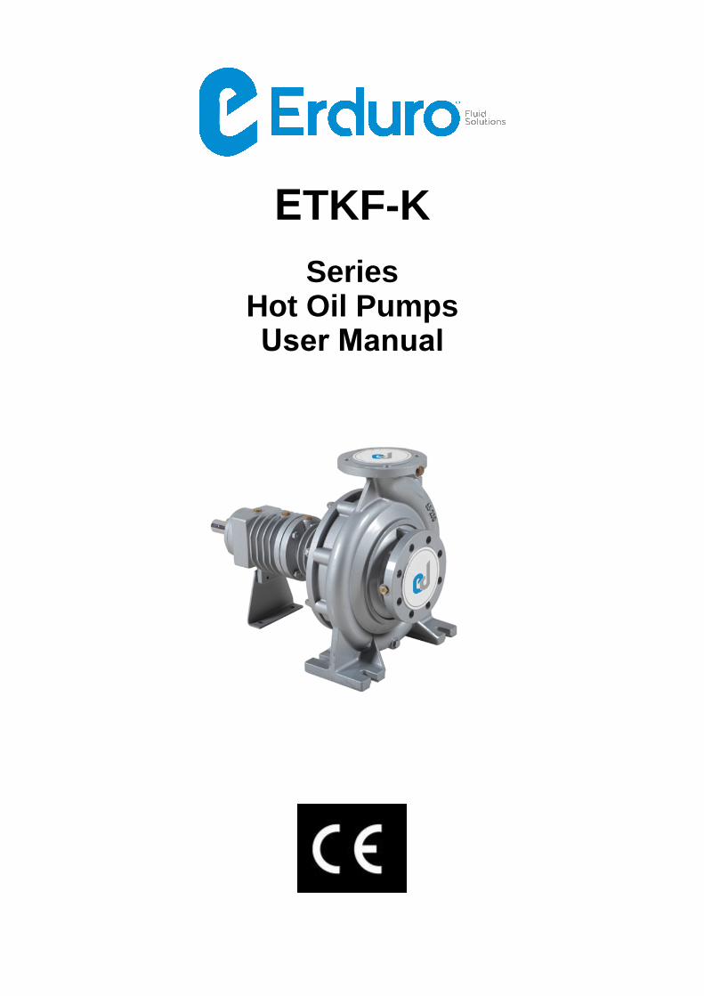
ETKF-K
Series Hot Oil PumpsUser Manual
ENGLISH INTRODUCTION AND USER MANUAL
TABLE OF CONTENTS
General Warnings 1 Safety Instructions 2 Application Areas 3 Shipping and Storage 4 Transportation 5 Storage 6 Installation 7 Electrical Connections 13 First Operation 15 Lubrication Control 17 Dismounting of Pumps and Repair 18 Pump Cross Section Drawing 19 Spare Parts 20 Failures and Troubleshooting 21 Tightening Moments 23 Noise Level 24 List Indicating Service Stations 25
GENERAL WARNINGS ABOUT USER MANUAL
Aim of this user manual is;
- To convey instructions about installation, maintenance and repair of pump, and to explain start, operation and stop methods of pump.
-. Absolutely keep this manual in a secured place to be accessed easily by official who is responsible for safe operation and maintenance of pump.
- Pump should not be operated under conditions which are not mentioned in purchase order. Because, operational conditions which are given in purchase order are considered at material selection and trial.
ERDURO , does not accept any warranty conditions for all kind of changes andrepair operations which are performed by user and unauthorized people.
- Instructions in this manual should carefully be examined and applied in every installation and operation process of pump for preventing misuse.
- Responsible Personnel should be experienced and have knowledge about related standards.
- If it is necessary to operate pump under conditions out of the ones those are mentioned in purchase order, please contact with ERDURO authorized service.ERDURO shall not be liable for damages which may occur because of operationunder conditions out of mentioned ones without written permission of service.
- If carried pumps shall not be installed immediately, it should be kept in an environment where temperature and humidity does not change so frequently. If appropriate precautions are not taken, very high temperatures and low temperatures and humidity may severely damage pump.
- User is responsible for control and installation to be performed by authorized personnel who have read and examined this user manual.
This user manual does not cover safety rules to be applied in usage area.
Usage tine for pumps which is determined and announced by Ministry is 5(five) years.
1
SAFETY INSTRUCTIONS
- You should absolutely obey the following safety instructions.
- Never touch the pump and pipes having temperature more than 80 ºC. Necessary precautions should be taken for warning users. (E.g Warning signs and signboards)
- Never operate pump in reverse direction.
- Do not walk over pump or pipes which are connected to pump.
- Any operation which will be done in pump should be performed by at least two staffs.
- No works should certainly be done over without stopping pump group.
- Power coming to pumps should be off and you should be sure that it will not operate again before you make any work
- Absolutely install the safety guards which were dismounted before after work in pump has finished.
- Tensions and cricks in pipe system absolutely should not reach to pump.
- Do not make any operation while pump and pipes which are connected to pump are under pressure.
- Cloths of personnel who will work over should be suitable and/or they should use safety equipments.
- Never do any operations when pump is still hot.
- Electrical connection related with pump and auxiliary equipments should be suitable with local rules and made by authorized personnel.
- Operate pump with only specified conditions.
- Do not insert your hand and fingers into holes and spaces over pump body.
- Be always careful while working with pumps discharging hazardous liquids.
2
TECHNICALLY DIFFERENT PORPERTIES of ETKF-K SERIES PUMPS
This series of pumps do not have any shape and appearance difference, technical
differences are given below.
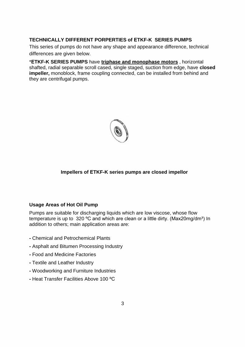
*ETKF-K SERIES PUMPS have triphase and monophase motors , horizontalshafted, radial separable scroll cased, single staged, suction from edge, have closed impeller, monoblock, frame coupling connected, can be installed from behind and they are centrifugal pumps.
Impellers of ETKF-K series pumps are closed impellor
Usage Areas of Hot Oil Pump
Pumps are suitable for discharging liquids which are low viscose, whose flow temperature is up to 320 ºC and which are clean or a little dirty. (Max20mg/dm³) In addition to others; main application areas are:
- Chemical and Petrochemical Plants
- Asphalt and Bitumen Processing Industry
- Food and Medicine Factories
- Textile and Leather Industry
- Woodworking and Furniture Industries
- Heat Transfer Facilities Above 100 ºC
3

Explanation of Pump Codes
ETKF-K 40 / 200
Pump Type
Rated Diameter of Discharge Flange (DN-mm)
Number of Stages (piece)
Technical information
Speed : 1450-2900 rpm
Discharge Flange : DN 32 …DN 150 mm
Suction and Discharge Flanges :TS ISO 7500-2/PN16,DIN2533/PN16
Operational Temperature : 320ºC
Ambient Temperature (Maximum) : +40ºC
Body Pressure : 16 bar
Isolation Class : F
Protection Class : IP55
Motor Connection : 3 Phase=380V-50Hz / 1 Phase=220V-50Hz
Motor Options (Optional) : Special Voltage Special Frequency
SHIPPING of PUMPS
- Check whether all materials in delivery list are sent.
- If there is damage during shipping please notify ERDURO Shipping Department
and Transportation company.
- If there are missing materials, immediately inform ERDURO Shipping Department. -
Check whether packaging is damaged during transportation.
- Please carefully take out packaged pump and accessories (if any). Check whether they are damaged during transportation.
- ERDURO is not responsible for any broken material during transportation. Pleasedon’t accept your goods if it is broken and inform ERDURO.
4
CARRYING
General Warnings
Absolutely obey the following rules during transportation.
- Use proper wooden crane, forklift, or hoisting mechanisms for unloading or loading wooden cases, packages, boxes and palettes depending on their weight and volume.
- Wear gloves, hard tip shoes and helmet during carrying works.
- Never stay under hoisting mechanism while loading or unloading pumps.
Pump and Motor Group Loading/Unloading
Before loading/unloading pump group please determined the following properties.
- Please find the lifting points.
- Please consider total weight and centre of gravity.
- Please consider the packaging external dimensions
- During loading/unloading make accelerating and braking operations as it shall not cause any damage for working personnel.
- Load lifting capacity should be suitable with pump and pump group weight.
- You should never stay under or near lifted load.
- Pump should be hoisted as it is indicated in Figure 1-1 and Figure 1-2 for not causing any damage in pumps. Motor hanging ring should absolutely not be used while lifting complete group.
- Load should be kept in lifted position more than required time.
- Pump and pump group should always be lifted and carried in horizontal position
5
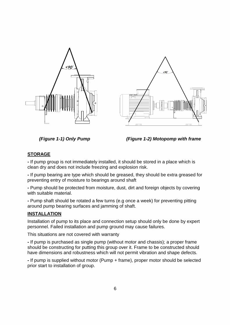
(Figure 1-1) Only Pump (Figure 1-2) Motopomp with frame
STORAGE
- If pump group is not immediately installed, it should be stored in a place which is clean dry and does not include freezing and explosion risk.
- If pump bearing are type which should be greased, they should be extra greased for preventing entry of moisture to bearings around shaft
- Pump should be protected from moisture, dust, dirt and foreign objects by covering with suitable material.
- Pump shaft should be rotated a few turns (e.g once a week) for preventing pitting around pump bearing surfaces and jamming of shaft.
INSTALLATION
Installation of pump to its place and connection setup should only be done by expert personnel. Failed installation and pump ground may cause failures.
This situations are not covered with warranty
- If pump is purchased as single pump (without motor and chassis); a proper frame should be constructing for putting this group over it. Frame to be constructed should have dimensions and robustness which will not permit vibration and shape defects.
- If pump is supplied without motor (Pump + frame), proper motor should be selected prior start to installation of group.
6
Following properties should be considered during motor selection.
- Maximum power of pump (in all operation ranges)
- Operational revolution of pump shaft
- Necessary power supply
- Motor Type
- Motor connection type (footed, flanged, horizontal, vertical etc.)
Coupling (clutch) setup is obtained by pump and motor having identical axis. All parts of pumps mainly pump and motor bearings may have damage because of vibration caused by unadjusted coupling.
Before start to pump installation
- Protecting parts in discharge and suction flanges should be removed and cleaned well.
- Pump should be installed in a places which does not have freezing or explosion risk and have well air conditioning.
- There should be enough space around pump for accessing pump easily and for maintenance operations and there should be sufficient height and space for lifting pump if necessary.
- Pump suction pipe should be as short as possible.
- You should be carefully work at pump installation ground preparation and installation of pump group into its place. Incorrect and careless installation causes early wearing of pump parts and failures.
- Pump ground should be so heavy to absorb vibrations and sturdy to prevent bends and adjustments defects. Ground concrete should completely be solidified, completed its plug time and proper stud bolts are placed in pump frame fixing holes and proper fixing lugs should be placed for using in making connections with welding. Concrete and plate upper surface should be horizontal and very smooth.
Installation
Installation of pump group to ground by anchoring stud bolts:
- Pump group is placed to center the stud bolt slots which are opened in ground concrete.
- Anchoring stud bolts are inserted through fixing holes over pump frame fixing holes and places into their slots.
- Pump group is placed over base concrete. Liquid balance is placed over pump discharge flange and horizontality of pump is controlled. If there is a horizontal imbalance in pumps position, steel wedges are put under frame and balance of pump group is obtained.
7
- Nuts of anchoring stud bolts are installed.
- Anchoring stud bolt holes are filled with concrete grout.
- Anchoring stud bolts are reciprocally tightened.
- Coupling setup is controlled in this situation.
- Concrete is poured into pump frame. Joining of poured concrete and ground concrete is cared.
- Complete binding of concrete is controlled and anchoring stud bolts are reciprocally tightened.
- Coupling adjustment is again controlled with template. If there is maladjustment, coupling adjustment is made again.
- Discharge and suction flange fixings of pump are controlled again. If there are unnecessary strains and cricks they are eliminated.
- Coupling guards are placed after coupling adjustment.
:Installation of pump group with concrete fixing plug :
- Pump is placed into ground concrete or the ground to be installed carefully.
Pump group frame fixing holes are marked to concrete. Pump group lifted again.
- Marked places where fixing plugs will be placed are drilled carefully according to standards.
- Fixing plugs are carefully placed into drilled places.
- Steps for installation with anchoring stud bold are made here with same order.
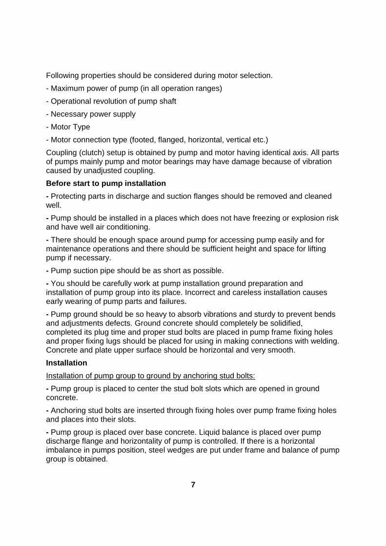
Clutch Adjustment
- Most important factor in operation of pump group without problem is the correct adjustment of clutch setup. Basic reason for many problems such as vibration, noise, bearing warming is lack of adjustment or not proper adjusted clutch. Therefore clutch setup should be done well and frequently controlled.
- Making clutch with flexible materials does not mean that it is a part which will correct a bad adjustment
(Figure 2) Clutch Adjustment
8
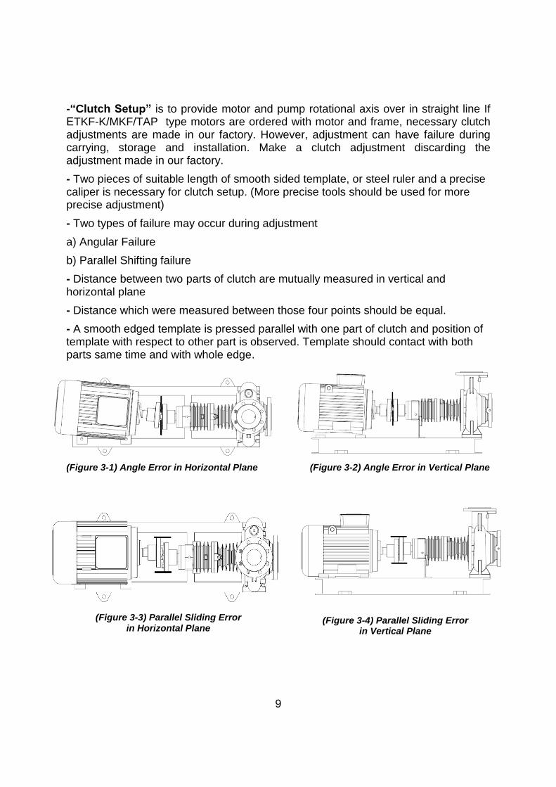
-“Clutch Setup” is to provide motor and pump rotational axis over in straight line If ETKF-K/MKF/TAP type motors are ordered with motor and frame, necessary clutch adjustments are made in our factory. However, adjustment can have failure during carrying, storage and installation. Make a clutch adjustment discarding the adjustment made in our factory.
- Two pieces of suitable length of smooth sided template, or steel ruler and a precise caliper is necessary for clutch setup. (More precise tools should be used for more precise adjustment)
- Two types of failure may occur during adjustment
a) Angular Failure
b) Parallel Shifting failure
- Distance between two parts of clutch are mutually measured in vertical and horizontal plane
- Distance which were measured between those four points should be equal.
- A smooth edged template is pressed parallel with one part of clutch and position of template with respect to other part is observed. Template should contact with both parts same time and with whole edge.
(Figure 3-1) Angle Error in Horizontal Plane (Figure 3-2) Angle Error in Vertical Plane
9
(Figure 3-3) Parallel Sliding Error in Horizontal Plane
(Figure 3-4) Parallel Sliding Error in Vertical Plane

This operation should be performed in reciprocal two places in horizontal and vertical plane. Adjustment errors can be in horizontal and vertical plane. Errors in vertical plane are eliminated by putting thin steel sheets under feet of pump or motor, errors in horizontal plane are eliminated by making adjustments in spaces of fixing holes or sliding motor in horizontal plane.
- Form and order of clutch adjustment are displayed in Figures 3-1,3-2,3-3 and 3-4.
ATTENTION: Adjustments should be checked after changes. Because an adjustment which is made in one direction may make other adjustment in other direction faulty.
Installation of Pipe Equipment
Never use the pump as an anchorage point or as a carrier for the piping.
-The pipelines should be supported very near the pump. It must be checked that any weight, stress or strains on the piping system should not be transmitted to the pump. Therefore after completing the piping installation, the bolt and connection on the suction and discharge nozzles must be loosened to ensure that there is not any stress on the piping system transmitted to the pump. The piping-induced forces and moments acting on the pump nozzles (e.g. due to torsion and/or thermal expansion) must not exceed the permissible forces and moments given in section K. An excessive, impermissible increase in the pipeline forces may cause leaks on the pump where liquid handled can escape into the atmosphere. Danger of life when hot liquids are handled. -The nominal sizes of the pump suction and discharge nozzles are no guide to the corrects sizes of the suction and discharge piping. The nominal bores of the pipes should be same as or greater than those of the pump nozzles. Never use pipes or accessories which have smaller bore than the pump nozzles. -Pipe joints should be by means of flanges with flange gaskets of proper size and material. Flange gasket must be centered between the flange bolts in a such way that there is no interference with the flow of the liquid. -Thermal expansions of the pipework and excessive vibrations should be accommodated by suitable means so as not to impose any extra load on the pump (Fig. 4) -The suction piping must not present any features likely to promote the formation of air pockets. Therefore the suction piping should have a slight downward slope towards the pump (Fig. 4) -An isolating valve should be installed in the suction pipe as close to the pump as possible. This valve should always remain fully open while the pump is running and must not be used to regulate the flow (Fig. 4) -A control or shut-off valve should be installed in the discharge pipe, as close to the pump as possible, to
10
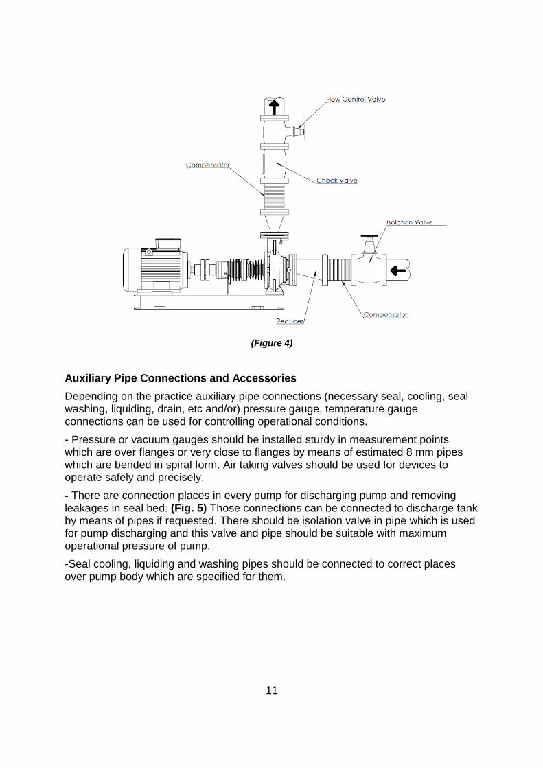
(Figure 4)
Auxiliary Pipe Connections and Accessories
Depending on the practice auxiliary pipe connections (necessary seal, cooling, seal washing, liquiding, drain, etc and/or) pressure gauge, temperature gauge connections can be used for controlling operational conditions.
- Pressure or vacuum gauges should be installed sturdy in measurement points which are over flanges or very close to flanges by means of estimated 8 mm pipes which are bended in spiral form. Air taking valves should be used for devices to operate safely and precisely.
- There are connection places in every pump for discharging pump and removing leakages in seal bed. (Fig. 5) Those connections can be connected to discharge tank by means of pipes if requested. There should be isolation valve in pipe which is used for pump discharging and this valve and pipe should be suitable with maximum operational pressure of pump.
-Seal cooling, liquiding and washing pipes should be connected to correct places over pump body which are specified for them.
11
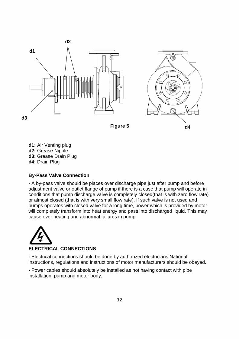
Figure 5
d1: Air Venting plug d2: Grease Nipple d3: Grease Drain Plug d4: Drain Plug
By-Pass Valve Connection
- A by-pass valve should be places over discharge pipe just after pump and before adjustment valve or outlet flange of pump if there is a case that pump will operate in conditions that pump discharge valve is completely closed(that is with zero flow rate) or almost closed (that is with very small flow rate). If such valve is not used and pumps operates with closed valve for a long time, power which is provided by motor will completely transform into heat energy and pass into discharged liquid. This may cause over heating and abnormal failures in pump.
ELECTRICAL CONNECTIONS
- Electrical connections should be done by authorized electricians National instructions, regulations and instructions of motor manufacturers should be obeyed.
- Power cables should absolutely be installed as not having contact with pipe installation, pump and motor body.
12
d1
d3
d2
d4
- Motor shaft should be rotated by hand before making electrical conditions to control whether it rotates easily.
- It is recommended to use PTC(Passive Thermal Control-Thermistor) in motors. However usage of those depends on customer. If PTC is used ends of those should be connected to motor terminal box and later should be connected to PTC control device in motor control panel.
- Electrical motors should be protected against overloading by circuit breakers and/or fuses. Circuit breakers and/or fuses should be selected with respect to full load values those are written in nameplate on motor.
- Compare and control voltage, ampere and frequency values which are given in motor nameplate with line values.
- Motor connection scheme can be found in motor terminal box or in handbook.
- Motor electrical connections should be done according to local Electrical Regulations and grounding connection should absolutely be done.
- Protection class of motor body and control system cases in pump should be at least EN 60029 IP 22. In addition to this, protection class of motor bodies and control systems in pump group should be determined according to operational and environmental conditions.
- Safety precautions which are determined in "Safety Instructions" should be applied. All power connections should be disconnected before starting to any work.
- Motor connection type changes according to motor mains power and connection type. Necessary connection types of jumpers in terminal box are displayed in Table 1 and Scheme 1a-1b and 1c
Start Type Motor Power
PN<4kW
Motor Power
PN >4kW
Mains Power
3~400V
Mains Power
3~400V
Direct Y-connection (1b) Δ-connection (1a)
Y/ Δ Star Delta Impossible Remove Jumpers (1c)
Table 1
13
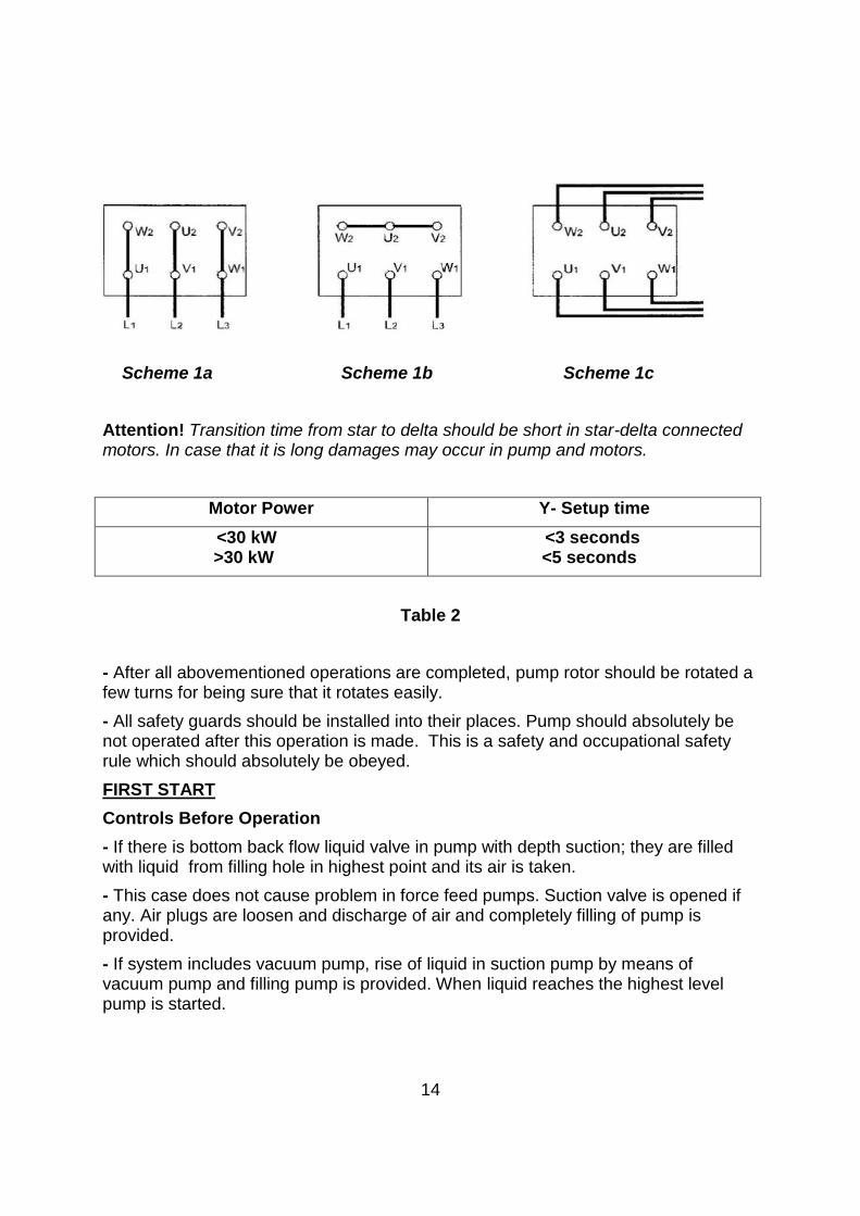
Scheme 1a Scheme 1b Scheme 1c
Attention! Transition time from star to delta should be short in star-delta connected motors. In case that it is long damages may occur in pump and motors.
Motor Power Y- Setup time
<30 kW >30 kW
<3 seconds <5 seconds
Table 2
- After all abovementioned operations are completed, pump rotor should be rotated a few turns for being sure that it rotates easily.
- All safety guards should be installed into their places. Pump should absolutely be not operated after this operation is made. This is a safety and occupational safety rule which should absolutely be obeyed.
FIRST START
Controls Before Operation
- If there is bottom back flow liquid valve in pump with depth suction; they are filled with liquid from filling hole in highest point and its air is taken.
- This case does not cause problem in force feed pumps. Suction valve is opened if any. Air plugs are loosen and discharge of air and completely filling of pump is provided.
- If system includes vacuum pump, rise of liquid in suction pump by means of vacuum pump and filling pump is provided. When liquid reaches the highest level pump is started.
14
- Pump bearings are shipped from the factory as being filled with grease which will be enough for one year.
- Before first start of pump, bearings should be checked whether there dirt has entered into it during shipment and installation. If bearings are dirt they should be completely be cleaned and greased again.
- If pump has waited before installation for a long time (more than 6 months), new grease should be inserted into bearings.
-Be sure that there is liquid in liquid tank and/or liquid source
- Be sure that pump and suction pipe is completely filled with liquid.
ATTENTION!
Never let pump run in dry conditions.
Determination of Rotation Direction
- ETKF-K type pumps rotates in clockwise direction when you look from clutch towards pump. This direction is shown with an arrow in pump body. Pump is operated for a short while and checked whether it rotates in correct direction. If protection guard is uninstalled during this operation, it should immediately be installed after this operation.
Starting Pump
- Check that suction valve is open and discharge valve is closed.
- Close the circuit breaker and start the motor.
- Wait motor to reach full speed. (Wait motor to pass delta in motors operation with star-delta)
- Observe the ammeter in panel and slowly open discharge valve. (If discharge pipe is empty in first start, do not open discharge valve completely and open in controlled way by controlling that value in ammeter is lower than motor rated values.)
-After valve is completely opened control the value which is read from ammeter whether it is same with the value at operational point. If the ammeter value is less than operational value adjust it by closing the valve. If it is greater check the installation and static height.
ATTENTION: If any of following problems occur while pump operates in nominal speed; pump should immediately be stopped and trouble should be eliminated.
1) Pump operates with over vibration.
2) Pump and motor connection bearings have over temperature.
3) Pressure is not enough.
15
4) Pump discharges no liquid.
5) Flow rate continuously decreases.
6) Motor operates overloaded
7) Pump operates with very much noise.
8) Pump does not discharge sufficient liquid.
Stopping the Pump
- Slowly close the discharge pump.
-. If there is liquid impulse prevention equipment in Discharge line and if the impulse which may occur is not in dangerous levels, you can stop the pump without closing the valve.
- Stop the motor. Watch that pump group has stopped calm and regular way.
- If there is external feed to seal, close this for decreasing the pressure in seal.
- If pump will be out of service for a long time close suction valve and auxiliary circuits if any.
- If there is frost danger and /or it will not be used for a long time, completely discharge liquid inside pump by means of discharging plug over pump body. Take necessary precautions against freezing risk.
Controls to be Made While Pump is Running
- Since pumps have mechanical seal it does not need any maintenance. A few amount of liquid may leak from mechanical seal but it is so small that it can not be noticed. If the amount of liquid coming from mechanical seal this means that seal surface is abraded and needs to be replaced. Lifetime of mechanical seal is mainly depends on cleanness of discharged liquid.
- Motor current should sometimes be controlled from ammeter over electrical panel which controls the motor. If current values are more than motor nameplate values there may be friction or squeezing in pump. Pump should immediately be stopped and mechanical and electrical controls should be done.
- If there are spare pumps in system, this type of pumps should be run for a short while at least once a week and controlled whether read for operation. Control with auxiliary elements if any.
- Pump should absolutely be run in closed valve condition (zero flow rate) for a long time.
- Pump should operate silent and without operation.
- Bearing temperatures should never exceed ambient temperature (more than 50ºC ). It should never exceed 80ºC
- Never operate pump without liquid.
16
LUBRICATION
Bearings in ERDURO pumps are designed to be lubricated with grease or liquid oiland having an easy maintenance.
OIL CONTROL
- If pump has waited before installation for a long time (more than 3 months), bearings should be greased. If liquid oil is used in bearings, old oil should be removed and filled with new oil.
- Before running the pump, pump bearings should be checked whether dirt has entered inside it. If there is dirt inside bearings they should completely be cleaned and new liquid oil or grease should be filled.
-Oil filling or adding operations should be determined by enterprise according to conditions in workplace and operation. This method is efficient.
-Pumps which are lubricated with liquid oil are shipped without oil. This type of pumps should be filled with oil up to indicator level before starting to operation.
SAFETY CONDITIONS
- Works should be done by obeying workplace occupational safety rules.
- Inside of pumps should be cleaned after fluid has been discharged from pump.
- Reliability of explosive, poisonous, hot and substances in crystal structure with respect to environment and human health should be assured.
- Considering that used cleaner and protector solvent wastes may give harm to environment and human health; precautions should be taken for preventing dissipation to environment and mixing to suction pool. Accumulation and putting the used waste solvents in disposal area should be cared.
- Working area where dismounting and installation works are performed should be clean.
- Pump should be free of all dangerous materials and be clean during return back.
- Lifting tools and equipments which are suitable with objective and occupational safety should be used in dismounting and installation operations.
DISMOUNTING OF PUMP AND REPAIR
ATTENTION! - Before starting to any operation over pump always disconnect the electrical connections and be sure that it will not run mistakenly. Certainly obey the instructions which are given in "Safety Instructions".
17
Dismounting of Pump
- Close the isolation valves in suction and discharge pipes.
- Open the fuses of electricity line fuses coming to motor as they will not carry current and remove control cable coming to motor from motor terminal box.
- Open the discharge plug under the scroll case and discharge the liquid inside pump.
- If the liquid inside pump is special, discharge it after taking necessary safety precautions.
- In liquid oil pumps, open discharge plug in bearing bed and discharge the oil.
-. Remove coupling and other safety guards.
- Remove pump suction and discharge flanges and auxiliary pipe connections and disconnect pump from pipe system. There is no need in pumps where intermediate partial clutches are used. In pumps where such kind of clutches are used rotor can be taken out without separating scroll case from pipe system.
- Separate motor from pump, (not necessary in pumps with coupling)disconnect pump from frame and take outside.
-Uninstall the bolts which connect roller bearing bed to scroll case.
-Uninstall the bolts which connect seal box to scroll case
- Remove the clutch intermediate part in pumps having coupling. Use the occurred space and take the bearing group and rotor outside.
-- Remove the clutch part over pump shaft by means of puller. Remove clutch wedge.
-Uninstall the impellor nut and remove clutch wedge. Use rust solvent if necessary.
Installation of Pump
-. Pump installation operation is made by reverse order of pump dismounting process.
- Before starting to installation operation, apply lubricious materials such as graphite, silicone or similar slippery substances over contact surfaces or bolt surfaces. If you can not find those substances use liquid oil.
- Do not use gaskets which you had removed. Use new ones having same dimensions. Be careful that new gaskets and O-rings are in same dimensions.
- Start installation from bearing group. Place the bearing into their places over shaft by using press. Place this part from clutch side towards bed housing. Place the bed covers from two side. Place the seal box and impellor and tighten the impellor nut.
-Connect the rotor group to body.
-Place the pump over the frame, install the motor and connect suction and discharge pipes and auxiliary pipes.
18
Pumps with Mechanical Seal
- Liquid leakage does not occur in a mechanical seal which properly operates. Mechanical Seal does not need maintenance in cases that it does not have visible liquid leakage. Besides this impermeability of mechanical seal should be regularly controlled.
- Strictly obey the instructions of mechanical seal manufacturers instructions in pumps where mechanical seals are used.
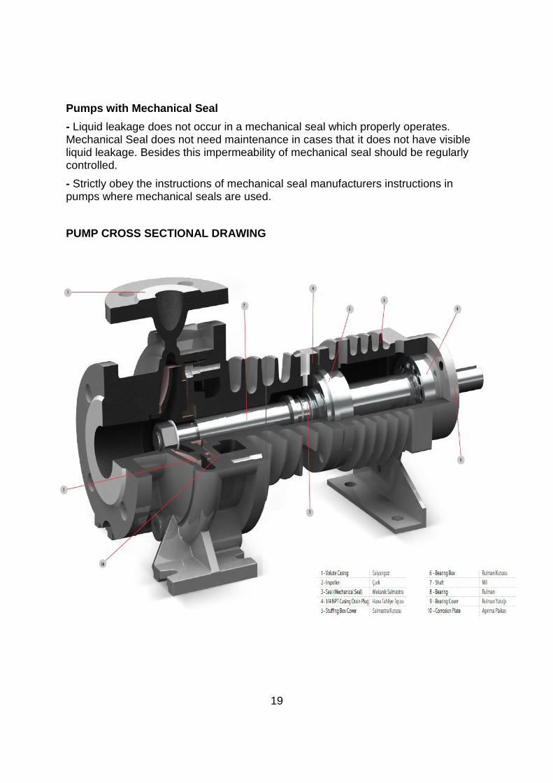
PUMP CROSS SECTIONAL DRAWING
19
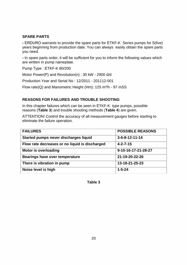
SPARE PARTS
- ERDURO warrants to provide the spare parts for ETKF-K Series pumps for 5(five) years beginning from production date. You can always easily obtain the spare parts you need.
- In spare parts order, it will be sufficient for you to inform the following values which are written in pump nameplate.
Pump Type : ETKF-K 80/200
Motor Power(P) and Revolution(n) : 30 kW - 2900 d/d
Production Year and Serial No : 12/2011 - 201112-001
Flow rate(Q) and Manometric Height (Hm): 125 m³/h - 97 mSS
REASONS FOR FAILURES AND TROUBLE SHOOTING
In this chapter failures which can be seen in ETKF-K type pumps, possible reasons (Table 3) and trouble shooting methods (Table 4) are given.
ATTENTION! Control the accuracy of all measurement gauges before starting to eliminate the failure operation.
Table 3
20
FAILURES POSSIBLE REASONS
Started pumps never discharges liquid 3-6-8-12-11-14
Flow rate decreases or no liquid is discharged 4-2-7-15
Motor is overloading 9-10-16-17-21-28-27
Bearings have over temperature 21-19-20-22-26
There is vibration in pump 13-18-21-25-23
Noise level is high 1-5-24
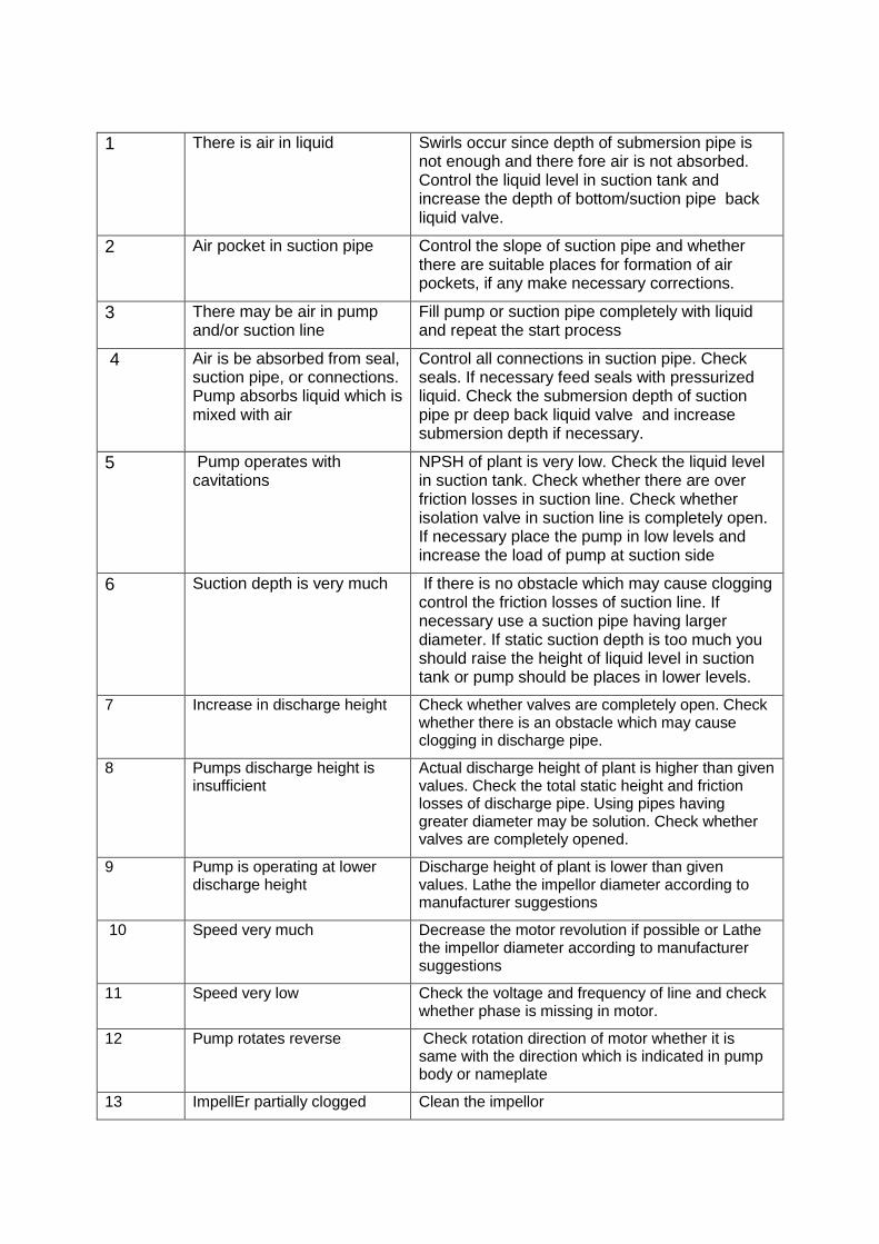
1 There is air in liquid Swirls occur since depth of submersion pipe is not enough and there fore air is not absorbed. Control the liquid level in suction tank and increase the depth of bottom/suction pipe back liquid valve.
2 Air pocket in suction pipe Control the slope of suction pipe and whether there are suitable places for formation of air pockets, if any make necessary corrections.
3 There may be air in pump and/or suction line
Fill pump or suction pipe completely with liquid and repeat the start process
4 Air is be absorbed from seal, suction pipe, or connections. Pump absorbs liquid which is mixed with air
Control all connections in suction pipe. Check seals. If necessary feed seals with pressurized liquid. Check the submersion depth of suction pipe pr deep back liquid valve and increase submersion depth if necessary.
5 Pump operates with cavitations
NPSH of plant is very low. Check the liquid level in suction tank. Check whether there are over friction losses in suction line. Check whether isolation valve in suction line is completely open. If necessary place the pump in low levels and increase the load of pump at suction side
6 Suction depth is very much If there is no obstacle which may cause clogging control the friction losses of suction line. If necessary use a suction pipe having larger diameter. If static suction depth is too much you should raise the height of liquid level in suction tank or pump should be places in lower levels.
7 Increase in discharge height Check whether valves are completely open. Check whether there is an obstacle which may cause clogging in discharge pipe.
8 Pumps discharge height is insufficient
Actual discharge height of plant is higher than given values. Check the total static height and friction losses of discharge pipe. Using pipes having greater diameter may be solution. Check whether valves are completely opened.
9 Pump is operating at lower discharge height
Discharge height of plant is lower than given values. Lathe the impellor diameter according to manufacturer suggestions
10 Speed very much Decrease the motor revolution if possible or Lathe the impellor diameter according to manufacturer suggestions
11 Speed very low Check the voltage and frequency of line and check whether phase is missing in motor.
12 Pump rotates reverse Check rotation direction of motor whether it is same with the direction which is indicated in pump body or nameplate
13 ImpellEr partially clogged Clean the impellor
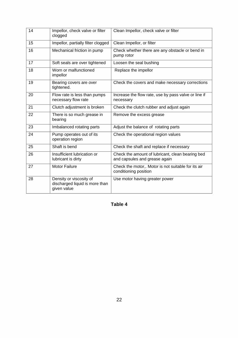
14 Impellor, check valve or filter clogged
Clean Impellor, check valve or filter
15 Impellor, partially filter clogged Clean Impellor, or filter
16 Mechanical friction in pump Check whether there are any obstacle or bend in pump rotor
17 Soft seals are over tightened Loosen the seal bushing
18 Worn or malfunctioned impellor
Replace the impellor
19 Bearing covers are over tightened.
Check the covers and make necessary corrections
20 Flow rate is less than pumps necessary flow rate
Increase the flow rate, use by pass valve or line if necessary
21 Clutch adjustment is broken Check the clutch rubber and adjust again
22 There is so much grease in bearing
Remove the excess grease
23 Imbalanced rotating parts Adjust the balance of rotating parts
24 Pump operates out of its operation region
Check the operational region values
25 Shaft is bend Check the shaft and replace if necessary
26 Insufficient lubrication or lubricant is dirty
Check the amount of lubricant, clean bearing bed and capsules and grease again
27 Motor Failure Check the motor,. Motor is not suitable for its air conditioning position
28 Density or viscosity of discharged liquid is more than given value
Use motor having greater power
Table 4
22
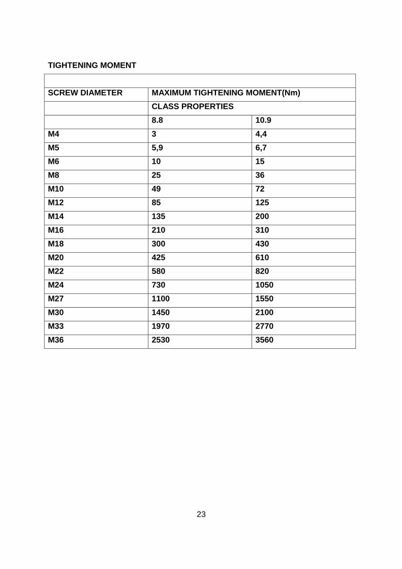
TIGHTENING MOMENT
SCREW DIAMETER MAXIMUM TIGHTENING MOMENT(Nm)
CLASS PROPERTIES
8.8 10.9
M4 3 4,4
M5 5,9 6,7
M6 10 15
M8 25 36
M10 49 72
M12 85 125
M14 135 200
M16 210 310
M18 300 430
M20 425 610
M22 580 820
M24 730 1050
M27 1100 1550
M30 1450 2100
M33 1970 2770
M36 2530 3560
23
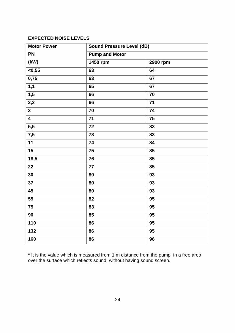
EXPECTED NOISE LEVELS
Motor Power
PN
(kW)
Sound Pressure Level (dB)
Pump and Motor
1450 rpm 2900 rpm
<0,55 63 64
0,75 63 67
1,1 65 67
1,5 66 70
2,2 66 71
3 70 74
4 71 75
5,5 72 83
7,5 73 83
11 74 84
15 75 85
18,5 76 85
22 77 85
30 80 93
37 80 93
45 80 93
55 82 95
75 83 95
90 85 95
110 86 95
132 86 95
160 86 96
* It is the value which is measured from 1 m distance from the pump in a free areaover the surface which reflects sound without having sound screen.
24
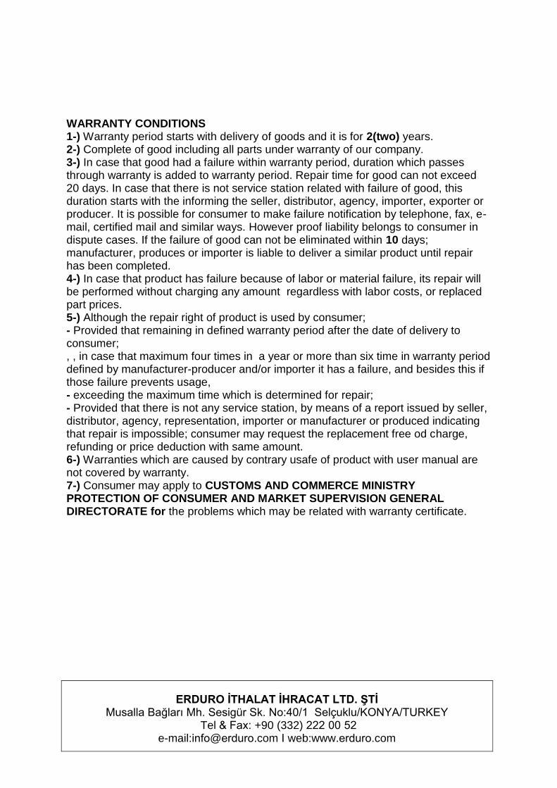
WARRANTY CONDITIONS 1-) Warranty period starts with delivery of goods and it is for 2(two) years. 2-) Complete of good including all parts under warranty of our company. 3-) In case that good had a failure within warranty period, duration which passes through warranty is added to warranty period. Repair time for good can not exceed 20 days. In case that there is not service station related with failure of good, this duration starts with the informing the seller, distributor, agency, importer, exporter or producer. It is possible for consumer to make failure notification by telephone, fax, e-mail, certified mail and similar ways. However proof liability belongs to consumer in dispute cases. If the failure of good can not be eliminated within 10 days; manufacturer, produces or importer is liable to deliver a similar product until repair has been completed. 4-) In case that product has failure because of labor or material failure, its repair will be performed without charging any amount regardless with labor costs, or replaced part prices. 5-) Although the repair right of product is used by consumer; - Provided that remaining in defined warranty period after the date of delivery to consumer; , , in case that maximum four times in a year or more than six time in warranty period defined by manufacturer-producer and/or importer it has a failure, and besides this if those failure prevents usage, - exceeding the maximum time which is determined for repair; - Provided that there is not any service station, by means of a report issued by seller, distributor, agency, representation, importer or manufacturer or produced indicating that repair is impossible; consumer may request the replacement free od charge, refunding or price deduction with same amount. 6-) Warranties which are caused by contrary usafe of product with user manual are not covered by warranty. 7-) Consumer may apply to CUSTOMS AND COMMERCE MINISTRY PROTECTION OF CONSUMER AND MARKET SUPERVISION GENERAL DIRECTORATE for the problems which may be related with warranty certificate.
ERDURO İTHALAT İHRACAT LTD. ŞTİMusalla Bağları Mh. Sesigür Sk. No:40/1 Selçuklu/KONYA/TURKEY
Tel & Fax: +90 (332) 222 00 52e-mail:[email protected] I web:www.erduro.com