Embed Size (px)
Citation preview
THERMAL HOT OIL PUMPS
KYP SERIES
OPERATING MANUAL
MAS DAF MAKİNA SANAYİ A.Ş.Head Office: Atasehir Bulvarı ATA Çarsı.K4.No:59
Tel: +90 (216) 456 12 00 (Pbx)- Fax:+90 (216) 456 25 00
İSTANBUL – TÜRKİYE E-Mail: [email protected]
Web : www.masgrup.com
EC DECLARATION OF CONFORMITY AT UYGUNLUK BEYANI
Manufacturer / İmalatçı : MAS DAF MAKİNA SANAYİ A.Ş.
Address / Adres : Ataşehir Bulvarı Ata Çarşı Kat:4 No:59 34758 Ataşehir/ İSTANBUL - TÜRKİYE
Name and address of the person authorised to compile the technical file Teknik Dosyayı derleyen yetkili kişi ve adresi
Vahdettin YIRTMAÇ Ataşehir Bulvarı Ata Çarşı Kat:4 No:59 34758 Ataşehir/ İSTANBUL - TÜRKİYE
The undersigned Company certifies under its sole responsibility that the item of equipment specified below satisfies the requirements of the Machinery Directive 2006/42/EC which is apply to it. The item of equipment identified below has been subject to internal manufacturing checks with monitoring of the final assessment by MAS DAF MAKİNA SANAYİ A.Ş.
Aşağıda tanımlanmış olan ürünler için Makine Emniyeti yönetmeliği 2006 / 42 / AT’nin uygulanabilen gerekliliklerinin yerine getirildiğini ve sorumluluğun alınmış olunduğunu beyan ederiz. Aşağıda tanımlanan ürünler iç üretim kontrollerine bağlı olarak MAS DAF MAKİNA SANAYİ A.Ş. tarafından kontrol edilmiştir.
Equipment / Ürün : THERMAL HOT OIL PUMPS/ KIZGIN YAĞ (ISI TRANSFER YAĞI) POMPALARI
Seri / Model-Tip : KYP
For pumps supplied with drivers/ Elektrikli pompa üniteleri Directives / Yönetmelikler 2006/42/EC Machinery Directive / Makine Emniyeti Yönetmeliği 2006/95/EC Low Voltage Directive / Alçak gerilim yönetmeliği 2004/108/EC Electromagnetic Compatibility Directive / Elektromanyetik Uyumluluk Yönetmeliği Regulations applied acc. to harmonize standards / Uygulanan Uyumlaştırılmış Standartlar ISO 12100‐1/A1, ISO 12100‐2/A1, EN ISO 14121‐1, EN 809/A1, EN 60204‐1:2006
For pumps supplied without drivers/ Motorsuz pompa üniteleri
We hereby declare that this equipment is intended to be incorparated into, or assembled with other machinery to constitute relevant machinery to comply with essential health and safety requirements of Directive
The machinery covered by this declaration must not be put into service until the relevant machinery into which it is to be incorporated has been declared in conformity with provisions of the directive
Ekipman, uygun bir makina oluşturmak amacıyla diğer ekipmanlar ile birleştirilirken yada monte edilirken gerekli sağlık ve güvenlik yönetmeliklerine uyulması gerekmektedir.
Bu bildiri kapsamında yönetmelikte belirtilen bütün hükümler yerine getirilmeden makinanın devreye alınmaması gerekmektedir.
Place and date of issue / Yer ve Tarih : İstanbul, 29.11.2010 Name and position of authorized person Yetkili kişinin adı ve görevi
: General Manager / Genel Müdür
Signature of authorized person Yetkili kişinin imzası
:

The Signs Used in This Operating Manual
1. IMPORTANT SAFETY PRECAUTIONS
In order to minimize the accidents during the mounting and putting into service of the pump, the following rules have to be applied:
1. Do not work without taking safety measures relevant to equipment. Cable, mask and safety band must be used when necessary.
2. Be sure there is adequate amount of oxygen and there is no toxic gaseous around.
3. Before using welding or any electrical equipment make sure that there is no risk of explosion.
4. Check the cleanliness of the area to take care of your health. (Dust, smoke, etc.)
5. Do keep in mind that there is a risk of having accidents related to electricity
6. Do not lift the pump before you check the transport equipment.
7. Be sure you have a by-pass line. 8. Use helmet, eye glasses and protective shoes for
your safety. 9. Place a protective barrier around the pump within
the necessary safety area. 10. Dust, liquids and gaseous that may cause
overheating, short circuit, corrosion and fire must be kept away from the pump unit.
11. By checking the noise level of the pump unit, take necessary measures to avoid noisy operation of the pump that can have harmful effects on the personnel and environment.
12. Be careful about the direction of transport and storage.
13. Cover appropriately the moving parts to avoid possible injury of the personnel. Mount the coupling guard and belting before starting-up the pump.
14. All the electrical and electronic applications must be performed by authorized person conforming EN 60204-1 and/or domestic instructions.
15. Protect the electrical equipment and motor against overloading.
16. If flammable and explosive liquids are pumped, ground connection of electricity should be carried out properly.
17. Do not expose the pump unit to sudden temperature variations.
18. All personnel who work with the waste water system need to be vaccinated in case of contagious diseases.
19. If the pump contains hazardous liquids, one must use protective helmet against the risk of splatter. One also must accumulate the liquid in a proper container against any risk of leakage. All Other Health and Safety Rules, Laws and
Regulations Must Be Applied
Read the instructions carefully in this operating manual and keep it for your future reference.
TABLE OF CONTENTS Page no Introduction 2 1. Important Safety Precautions 2 2. General 3 3. Safe Working Conditions 3 4. Technical Information 4 5. Transport And Storage 5 6. Assembly/Installation 6
6.1. Installation 6 6.2. Type of Connection 6 6.3. Foundation 6 6.4. Coupling Alignment 7 6.5. Piping 8 6.6. Motor Connection 9
7. Commissioning ,Start Up And Operating 9 7.1. Preparations Before Start-Up 9 7.2. Comissionning 10 7.3. .Shut Down And Restart-Up 11
8. Maintenance/Repair 11 8.1. Maintenance 11 8.2. Repair 12 8.3. Spare Parts 13
9. Noise Level And Vibration 13 10. Disassembly, Repair and Reassembly 13
10.1. Disassembly of Centrifugal Pump 13 10.2. Reassembly 14
11. Possible Failures, Causes, Solutions 13 12. Pump Dimensions Table And Weights 18 13. Tightening Torques 19 14. Forces And Moments At The Pump Flanges 19 15. Typical Piping 20 16. KYP Sectional Drawing And Spare Part List 21 17. KYP Exploded View 22 INTRODUCTION
• This manual contains instructions for the installation,
operation and maintenance of the KYP type single stage, end suction, volute type heat transfer pumps of MAS DAF MAKİNA SAN. A.Ş.
• Please read carefully this manual and apply all the instructions to operate pumps without problems. Pumps shall be used for their intended duties. In this manual, there are information on operating conditions, installation, starting-up, settings and main controls of pumps.
• These operating and maintenance instructions contain MAS DAF MAKİNA SAN. A.Ş.`s suggestions. The special operating and maintenance information of the plumbing that a pump is fitted to is not considered in these instructions. This information must be given by plumbing constructors only
• Please refer to instructions of plumbing constructors • Please pay attention to the warnings in this manual and ensure
that it is read before the installation-start up process. MAS DAF MAKİNA SAN. A.Ş. is not responsible for the accidents resulting from negligence.
• If you cannot find an answer to your questions in this manual, it is suggested that you contact MAS DAF MAKİNA SAN. A.Ş. Please inform us about the rated value and especially the serial number of the pump when you get in contact for help.
• The safety instructions in this manual cover the current national accident protection regulations. Beside all of these, an operation, work and safety measure imposed by the costumer has to be applied.
Warning sign against the electrical risk
Sign for the operator’s safety.
3
2. General 2.1 Definition of Pump and Usage Areas KYP series pumps are single stage, end suction volute type heat transfer pumps.
They are used in. • Chemical and petrochemical facilities • Paper mills and sugar factories • Food and pharmaceutical factories • Leather industry • Plastics and synthetic fiber factories • Rubber industry • Cooking and heating ovens • Textile industry • Laundries • Heat transfer facilities which utilize liquids that
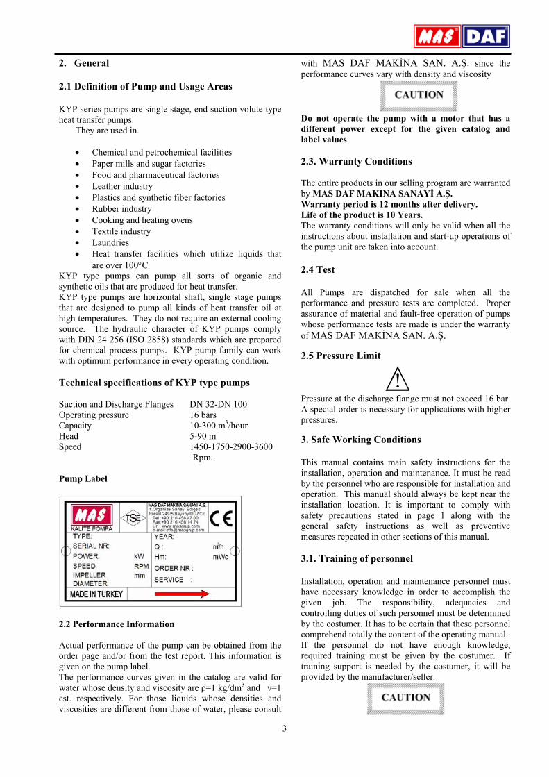
are over 100°C KYP type pumps can pump all sorts of organic and synthetic oils that are produced for heat transfer. KYP type pumps are horizontal shaft, single stage pumps that are designed to pump all kinds of heat transfer oil at high temperatures. They do not require an external cooling source. The hydraulic character of KYP pumps comply with DIN 24 256 (ISO 2858) standards which are prepared for chemical process pumps. KYP pump family can work with optimum performance in every operating condition. Technical specifications of KYP type pumps Suction and Discharge Flanges DN 32-DN 100 Operating pressure 16 bars Capacity 10-300 m3/hour Head 5-90 m Speed 1450-1750-2900-3600 Rpm. Pump Label
2.2 Performance Information Actual performance of the pump can be obtained from the order page and/or from the test report. This information is given on the pump label. The performance curves given in the catalog are valid for water whose density and viscosity are ρ=1 kg/dm3 and ν=1 cst. respectively. For those liquids whose densities and viscosities are different from those of water, please consult
with MAS DAF MAKİNA SAN. A.Ş. since the performance curves vary with density and viscosity
Do not operate the pump with a motor that has a different power except for the given catalog and label values. 2.3. Warranty Conditions The entire products in our selling program are warranted by MAS DAF MAKINA SANAYİ A.Ş. Warranty period is 12 months after delivery. Life of the product is 10 Years. The warranty conditions will only be valid when all the instructions about installation and start-up operations of the pump unit are taken into account. 2.4 Test All Pumps are dispatched for sale when all the performance and pressure tests are completed. Proper assurance of material and fault-free operation of pumps whose performance tests are made is under the warranty of MAS DAF MAKİNA SAN. A.Ş. 2.5 Pressure Limit
Pressure at the discharge flange must not exceed 16 bar. A special order is necessary for applications with higher pressures.
3. Safe Working Conditions This manual contains main safety instructions for the installation, operation and maintenance. It must be read by the personnel who are responsible for installation and operation. This manual should always be kept near the installation location. It is important to comply with safety precautions stated in page 1 along with the general safety instructions as well as preventive measures repeated in other sections of this manual.
3.1. Training of personnel Installation, operation and maintenance personnel must have necessary knowledge in order to accomplish the given job. The responsibility, adequacies and controlling duties of such personnel must be determined by the costumer. It has to be certain that these personnel comprehend totally the content of the operating manual. If the personnel do not have enough knowledge, required training must be given by the costumer. If training support is needed by the costumer, it will be provided by the manufacturer/seller.
4
Untrained personnel and unwillingness to comply with safety instructions may be risky for both machine and environment. MAS DAF MAKİNA SAN.A.Ş. is not responsible for this kind of damages.
3.2. Hazardous conditions that may occur when one does not comply with the safety instructions Incompliance with safety regulations may put the personnel, the environment and the machine in danger and thus may cause damages. Incompliance with safety regulations may give rise to situations listed below: Important operational functions of the factory may stop Maintenance may get difficult. One may get injured by electrical, mechanical or chemical hazards. 3.3. Safety measures for operator Dangerous, hot or cold components in the pump area must be covered so that one cannot touch them. Moving components of the pump (such as rigid coupling) must be covered so that one cannot touch them. Those covers must not be dismounted while the pump is running. Dangers that results from electrical connections must be removed. To get more information about this subject, you can refer to VDE and domestic electrical instructions..
3.4. Safety measures for maintenance and installation The costumer must assure that all maintenance, check and installment tasks are performed by qualified personnel. Repair work must only be performed while the machine is not running. The pump and its auxiliary system must be cleaned thoroughly if it contains hazardous liquids. At the end of the repair work, all safety and protective equipment must be re-installed. 3.5. Spare parts replacement Replacement of spare parts and all modifications must be done after contacting with the manufacturer. Spare parts and accessories certified by the manufacturer are important for the safe operation of the system. Notice: MAS DAF MAKİNA SAN. A.Ş. is not responsible from the usage of improper spare parts.
4. Technical Information 4.1. Design Regarding their hydraulic properties, KYP pumps single stage, horizontal shaft, volute type centrifugal pumps. Due to its mechanical design, the natural air convection forms a drastic temperature decrease from the casing to the bearing. Thus, without using an external cooling system, the mechanical seals and bearings can be cooled sufficiently. The pump and the motor are coupled with an elastic coupling over a common base-plate.
4.1.1. Volute Casing The single piece pump is dismountable in the vertical plane. The suction and discharge flanges and the pump pedestal feet are on the casing. Since the rotor can be dismounted from the rear side, there is no need to dismount the pump casing and the plumbing when maintenance and/or repair is needed. When a secondary component coupling is used, there is no need to dismount the motor. The suction flange is in the front, and the discharge flange is above the pump. 4.1.2. Location of flange – flanges Suction flanges in axial direction DN 50 – DN 125 Discharge flange radially upward DN 32 – DN 100 Discharge flanges DN 2533 – PN 16 4.1.3. Auxiliary fittings Please refer to the technical drawing of the pump for necessary auxiliary fitings. 4.1.4. Impeller Single suction, enclosed type, full centrifugal impellers are used. Radial blades behind the impeller are used in order to lower the seal pressure and to maintain axial balancing. 4.1.5. Shaft The mechanical seal which maintains impermeability is embedded in the ball bearing, in front of the second bearing and close to the coupling. This placement signifies that the mechanical seal dwells in the low temperature region; far from the volute; which is a significant heat source. Therefore the life of the mechanical seal increases. The primary bearing is placed in between the impeller and the mechanical seal and is lubricated by the discharged fluid. Just behind the impeller, a packet type security seal, which withstands high temperature, sits. Thanks to this seal that, in case there is a malfunctioning in the mechanical seal, an increase in the escape flow rate is prevented. The second bearing dwells on the side of the coupling and is lubricated by grease. 4.2. Construction of pump group 4.2.1. Drive A hermetic, 3 phase, totally enclosed, fan cooled, squirrel caged, IM 1001B3 type electrical motor which complies with DIN (42673) IEC, VDE and TSE standards is used to drive the pump in proper speed and power.
Specifications of electrical motor Isolation class : F Protection class : IP 54-IP 55 Frequency : 50 Hz.
5
Running type : S1 Start up type :
• 3x380 V(Y) up to 4 kW • More than 4 kW, 3x380(Δ) + (Y/ Δ)
4.2.2. Coupling and coupling guard A flexible shaft coupling with or without secondary component in accordance with DIN 740 is used. A coupling guard is given in accordance with EN 294 in case of the pump group includes the coupling and chassis
Pump can only be run with a coupling guard in accordance with EN 294 according to the safety instructions
4.2.3. Base Plate It is manufactured from stell plate or U profile stell in accordance with DIN 24259. 5. Transport and Storage Suction, discharge and all auxiliary fittings must be closed during transport and storage. Dead-end covers must be removed while the pump unit is being installed. 5.1. Transport Pump and pump group must be carried safely to the installation location by lifting equipments.
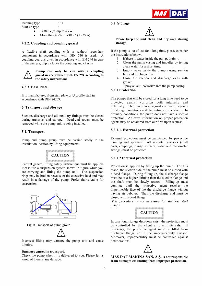
Current general lifting safety instructions must be applied. Please use a suspension system shown in figure while you are carrying and lifting the pump unit. The suspension rings may be broken because of the excessive load and may result in a damage of the pump. Prefer fabric cable for suspension.
Fig.1: Transport of pump group Incorrect lifting may damage the pump unit and cause injuries. Damages caused in transport. Check the pump when it is delivered to you. Please let us know of there is any damage.
5.2. Storage
Please keep the unit clean and dry area during storage.
If the pump is out of use for a long time, please consider the instructions below.
1. If there is water inside the pump, drain it. 2. Clean the pump casing and impeller by jetting
clean water for a short time. 3. Empty water inside the pump casing, suction
line and discharge line. 4. Close the suction and discharge exits with
gasket. Spray an anti-corrosive into the pump casing. 5.2.1 Protection The pumps that will be stored for a long time need to be protected against corrosion both internally and externally. The persistence against corrosion depends on storage conditions and the anti-corrosive agent. In ordinary conditions, the pump does not have a special protection. An extra information on proper protection agents may be obtainred from our firm upon request. 5.2.1.1. External protection External protection must be maintained by protective painting and spraying. All uncoated surfaces (shaft ends, couplings, flange surfaces, valve and manometer fittings) must be protected. 5.2.1.2 Internal protection Protection is applied by filling up the pump. For this reaon, the suction side of the pump must be closed with a dead flange. During filling-up, the discharge flange must be at a higher altitude than the suction flange and the shaft must be slowly rotated. Filling-up must continue until the protective agent reaches the impermeable face of the the discharge flange without having air bubbles. Then the discharge end must be closed with a dead flange This procedure is not necessary for stainless steel pumps
In case long storage durations exist, the protection must be controlled by the client at given intervals. If necessary, the protective agent must be filled from discharge flange up to the impermeability surface. Moreover, impermeability must be controlled against deteriorations.
MAS DAF MAKİNA SAN. A.Ş. is not responsible from damages emanating from improper protection.
6
5.2.1.3 Emptying the protective agent Before the pump is operated protective oil must be emptied. One must make sure that the waste is disposed according to the environmental rules
After a long storage duration, before commissioning, the structural elasticity of all of the elastomers (O-rings, seals) has to be checked. They need to be replaced immediately when the slightest damage is detected. The elastomers which are made of Ethylene-propylene need to be renewed. 6. Assembly / Installation 6.1. Installation In our standard production, the pump and the motor have been installed in a common base plate.
6.1.1. Location of Installation Pump will be installed in a location where the control and the maintenance of the pump are easily made. The pump room should be suitable for operation of lifting systems such as freight elevator, forklift, etc. 6.1.2. Location of Installation – Local Ambient Temperature When the local ambient room temperature exceeds +40°C in a pumping system, suitable ventilation should be provided in order to remove the heat dissipated to the environment and supply fresh air. 6.2. Type of Connection Type of connection depends on the design type and the size of the pump and the motor, as well as the local installation conditions. Foot-mounted horizontal pump-motor units have been installed in a common base plate.
6.3. Foundation 6.3.1. General Base plate of the pump must be grouted. The foundation shall be of concrete or steel framework. NOTE: The foundation shall distribute the weight of the pumping group evenly. 6.3.2. Main Properties of the Steel Framework Bases Foundations with steel framework shall be designed in such a way that the base plate is bolted or welded contacting to all area.
If base plate is supported from only four points, pump group will stay in the middle, causing misalignment of the coupling and increasing the noise level.
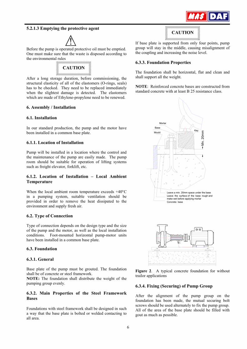
6.3.3. Foundation Properties The foundation shall be horizontal, flat and clean and shall support all the weight. NOTE: Reinforced concrete bases are constructed from standard concrete with at least B 25 resistance class.
Mn .
20m
mMould
Base
Mortar
Key
Leave a min. 20mm space under the base
make wet before applying mortarLeave the surface of the base rough and
Concrete base
Figure 2. A typical concrete foundation for without trailor applications 6.3.4. Fixing (Securing) of Pump Group After the alignment of the pump group on the foundation has been made, the mutual securing bolt screws should be used alternately to fix the pump group. All of the area of the base plate should be filled with gout as much as possible.

7
NOTE: While securing pump group with the mortar bonding agents and molding, one has to make sure that the base plate contacts completely with the base with no cavities between the surfaces. Inside of the chassis (frame) should be completely filled with concrete. 6.4 Coupling Alignment 6.4.1. General
For a proper operation of a pump group, a good alignment of the coupling is necessary. Vibration, noise, overheating of the bearings, overcharge problems can be attributed to the misalignment of coupling or using an improper coupling.
Flexible coupling does not correct the axial misalignments between the pump and the motor axes. However, it allows to pinpoint the misalignments.
In order to avoid overheating, vibration, noise and wearing of the rolling bearings, alignment of the coupling has to be made properly and checked often. Do not use a different coupling other than the original type installed on pumping group
6.4.2 Method of Coupling Alignment
In order to make the alignment of the coupling, it is required to have at least two smooth edged metal pieces (e.g. a steel ruler or a gauge stick) and one precision calipers. (Figure 3.) (For more precision alignments, special apparatus can be used).
Coupling misalignments in general are of two kinds: 1. Parallel axis misalignment. In order to control parallel axis misalignment, a smooth edged gauge stick is pressed axially over the upper half of the coupling. Then, the gauge stick is checked for the other half of the coupling. For alignment, the gauge stick shall be in contact with both of the halves at the same time. This procedure shall be repeated for four sides of the coupling. (i.e., top, bottom, left and right sides of the coupling). When all four sides give reasonably accepted results, alignment of the coupling has been ensured. 2. Angular Misalignment In order to control the angular misalignment, the distance between the two halves of the coupling is measured in both horizontal and vertical planes. Measurements taken at four points shall be in agreement for the alignment. Misalignments can be in horizontal or vertical planes. Misalignments in horizontal plane can be fixed by placing sheet iron at the bottom of the pump or motor base, while misalignments in vertical plane can be fixed by sliding the pump or the motor in horizontal plane.
Install the coupling guard only when the alignment of the coupling is checked
Figure 3. The control of the coupling alignment in horizontal and vertical planes.
6.4.3 Pump and Motor Mounting (Coupling)
If the coupling of the pump group is to be mounted on site, the following procedure should be followed: 1. Coat the shaft tip of the pump and the motor
sides with a sheet of molybdenum disulfide. 2. Push the coupling halves with a driving
apparatus towards the pump and the motor shafts, until the shaft is fit to snag to the hub of the coupling. If a driving apparatus is not available, heating coupling halves (with coupling rubbers off) to an approximately 100 0C may help the pushing. It is important that axial force is prevented from occurring while mounting the coupling. Support pump shaft from the impeller side, and motor shaft from the fan side while mounting the coupling. If necessary, dismantle the fan cover.
3. Screw the two bolts in coupling hub. 4. Make sure that a suitable spacing is left
between the coupling halves while mounting pump and the rotor.
5. Horizontal pump groups mounted on the base plate or directly mounted on the base, alignment of the coupling shall be as described in 6.4.2.
6. Put into place the coupling guard.
90°
90°
90°
Y1
X1

8
According to the accident prevention regulations, all preventions and protective devices should be in their intended place and in operational form.
6.5 Piping 6.5.1 General
• Do not use the pump as the hinged support for the
piping system. • Put enough supports under the piping system in order
to carry the weight of the pipe and fittings. • Avoid piping system loads on pump by installing
flexible components (compensator) to suction and discharge of the pump.
• By mounting flexible supporting items, take into consideration the fact that these items may elongate under the pressure. Especially, the supporting items shall be placed in the direction of discharge flange axis of the pump (generally in vertical direction).
• Suction pipe shall be in a constantly increasing slope to the pump. Air in the suction pipe shall be arranged to move into the pump.
• Discharge piping shall be in a constantly increasing slope to the reservoir or discharge point, without up and downs which can cause air pockets in the piping system. At locations where forming of air pockets is possible, special items like air valve and air cock are mounted to evacuate the trapped air.
• It is important that pipe diameter and fittings are at least as much as the pump opening diameter or preferable one or two size higher. One should never use fittings with smaller diameters than the pump exit diameter. In particular, preferred fittings like foot valve, strainer, filter, check valves and valves shall have large free passing area, and low friction loss coefficient.
• For piping systems with hot liquids, thermal expansions are to be taken into account and compensators shall be mounted in accordance with these expansions. Caution shall be exercised to avoid the loading of pump in this installation.
6.5.2 Specification of work in piping installation
In installation of pipes, follow the procedures below certainly. • Install the pump on the concrete base as illustrated in
Figure 2. • Take out the guards (placed by the manufacturer) from
suction and discharge openings of the pump. • Close the suction and discharge flanges with rubber
gaskets. This precaution is important to avoid the undesired substances (weld crust, weld slag, sand, stone, wood piece etc.) get into the pump. Do not take off this gasket until the installation is completed.
• Start the installation of piping from the pump side. Do the necessary assembling and welding of the parts in a successive order.
• In these operations, do not neglect to put the necessary supports in their respected locations.
• Following above procedure, complete all piping system at suction side up to the suction tank (or foot valve if available), at discharge side up to do discharge collector and discharge pipe.
• When all installation and welding process is done and the heat dissipated by welding is removed, dismantle all the bolted connections from the suction tank to discharge pipe. Take out all demountable parts.
• Clean these parts and then paint body coat completely inside and outside.
• Mount the parts again in their intended places. However, this time start from the discharge line and move downward to the pump. In this instance, do not forget to check the flange gaskets. If needed, (for example deformation during welding) replace them.
• Concerning the connection of the pump flanges to piping, in case of misalignment of axis and flange holes, do not force the system to eliminate the misalignment. Forcing the system may cause difficult-to-correct problems.
• If there is an axial misalignment between the flanges of the pump and the pipe, due to the welding or any other reasons, cut the pipe from a suitable location in order to fix the problem. Connect the pipe (pump side) to the pump. After carrying out the necessary correction, connect the parts again by welding.
• Dismantle and clean the last welded part. Repaint again and mount on its place.
• After all these processes are accomplished, remove the rubber gasket from the suction and discharge openings. Open their holes and mount them again on their intended place.
6.5.3 Specification of work after installation of
piping and piping system
Figure 8. Piping system
S uc tion
S uc tion L ine (B u ttom W iew )
S uc tionflange
flange
S uction L ine (Top W iew )
9
An illustrative piping system is shown in Figure 10. Appropriate manometers shall be mounted on suction and discharge pipe lines.
6.6 Motor Connection
Motor shall be connected by an electrical technician according to the connection (switch) diagram. Local electricity policies and current VDE regulations have to be applied.
• Electrical connections have to be made by authorized electricians.
• In dismantling the pump, make sure the electricity is cut off before taking the motor cover out.
• Use the appropriate electrical connection to the motor.
In environments where there is a risk of explosion, prescribed protective law and regulations shall be applied by competent authorities.
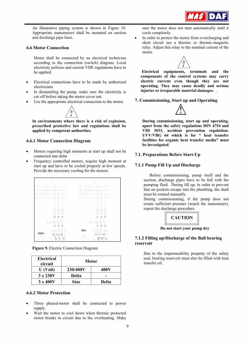
6.6.1 Motor Connection Diagram • Motors requiring high moments at start up shall not be
connected star-delta • Frequency controlled motors, require high moment at
start up and have to be cooled properly at low speeds. Provide the necessary cooling for the motors.
Figure 9. Electric Connection Diagram
Electrical circuit Motor
U (Volt) 230/400V 400V 3 x 230V Delta - 3 x 400V Star Delta
6.6.2 Motor Protection • Three phased-motor shall be connected to power
supply. • Wait the motor to cool down when thermic protected
motor breaks in circuit due to the overheating. Make
sure the motor does not start automatically until it cools completely.
• In order to protect the motor from overcharging and short circuit use a thermic or thermic-magnetic relay. Adjust this relay to the nominal current of the motor.
Electrical equipments, terminals and the components of the control systems may carry electric current even though they are not operating. They may cause deadly and serious injuries or irreparable material damages. .
7. Commissioning, Start up and Operating
During commissioning, start up and operating, apart from the safety regulations DIN 4754 and VDI 3033, accident prevention regulation: UVV/VBG 64 which is for “ heat transfer facilities for organic heat transfer media” must be investigated.
7.1. Preparations Before Start-Up 7.1.1 Pump Fill Up and Discharge
Before commissioning, pump itself and the suction, discharge pipes have to be full with the pumping fluid. During fill up, in order to prevent that air pockets escape into the plumbing, the shaft must be rotated manually. During commissioning, if the pump does not create sufficient pressure (watch the manometer), repeat the discharge procedure.
Do not start your pump dry
7.1.2 Filling up/Discharge of the Ball bearing reservoir
Due to the impermeability property of the safety seal, bearing reservoir must also be filled with heat transfer oil.
W1V1U1
W2 U2 V2
U1 V1 W1
W2 U2 V2
DeltaStar

10
1 2
For filling up and discharge, the dead plugs at fitting 1 and fitting 2 are removed. The filling from fitting 1continues until the clean heat transfer oil comes up from fitting 2. To obtain a proper flow the heat tansfer oil may be heated a priori. If there is no more air coming from fitting 2, the plugs may be replaced back.
7.1.3 Checking the Direction of Rotation
The direction of rotation must be same with the indication on the casing. To control the direction of rotation, the pump may be operated in the opposite direction for a little while. Opposite direction of rotation decreases the performance and may damage the pump. In a three phase pump, the direction of rotation may be corrected by swapping two phases.
7.2 Commissioning 7.2.1 Checking of Coupling Alignment
Prior to commissioning and after the first operation that attains operating temperature, the coupling alignment must be checked. The pump shaft must be rotating easily without any contraction.
7.2.2 Commissioning
To prevent excessive loading, the pump must be commissioned against closed discharge valve. The valve at the suction end must be kept fully open.
7.2.3 Drive
Start the pump. Pay attention to the characteristics of the product. Apply to the instructions of MAS DAF MAKİNA SAN. A.Ş.
7.2.4 Adjustment of Performance Values
Start the pump and bring the system to 100-130°C. To do this, the suction side stop valve must be fully open. The discharge side stop valve must be open such that the pump heats the entire system or such that it
maintains a minimum discharge capacity (see minimum capacity). Operate the system in this way until all the water vapor that is expected to exist in heat transfer oil evaporates. Then bring the system to operating temperature.
When the operating temperature is attained, open the discharge side valve until one reaches the desired disharge side pressure.
7.2.5 Minimum Capacity In order prevent the damage that may emanate
from the excessive heating up of the pumping liquid, the pump must not be operated with closed valve except primary commissioning.
Minimum Capacity The power needed by the pump at its own impeller diameter, valve closed (kW) x 0.5= Min. capacity (m3/h)
7.2.6 Temperature
One must avoid sudden shocks.
7.2.7 More Specific Weight and Viscosity
If the specific weight and the viscosity of the pumping fluid is more than the values foreseen in pump selection, the motor may be loaded more than necessary.
7.2.8 More Capacity
If the capacity is more than the value forecast while designing the pump, check whether the suction is still sufficient or not. Otherwise, cavitation may occur. Requirement: NPSHavail>NPSHreq.
The capacity should not be more than the one that is speciified for ηopt.
7.2.9 Spare Pump
A spare pump must be awaiting as if it is going to be commissioned any time. For this reason, the suction side stop valve must be fully open all the time. The pump must be secured against return flow by placing a check valve to the discharge side.
In case of pump breakdown, against the risk of having unacceptable oil temperatures, a pump with appropriate capacity and head must be kept ready. Two separate energy sources must accompany both the operating and the spare pumps.

11
7.3 Shut-Down and Restart-Up 7.3.1. Shut-down Process
Keeping In Operation After the heating source is switched off, the pump must continue to operate for a little while. The temperature of the pumping fluid must be brought down to a level where there is no heat accumulation within the pump. Discharge Line If a check valve is placed on the discharge line, the discharge valve may be left open. If a check valve does not exist, the discharge valve must be closed. Drive Shut down the motor. Make sure that the pump slows down and stops without hammering. Suction Line Close the suction line valve..
7.3.2. Restart-Up
Before restarting the pump, make sure that the pump shaft is not rotating. If there is a leakage in the suction line shut down valve, the pump may turn in the opposite sense due to counter flow.
If the pump shaft rotates in the opposite sense, the pump may be damaged..
7.3.3. Important points to consider when the pump is not used for a long time
ıf the pump is not operated for a long time, there is the risk of freezing. The pump must then be emptied and preserved.
8. Maintenance/Repair
8.1. Maintenance
Conform with all the instructions that are given for safety at the beginning of this manual.
Regular monitoring and maintenance will increase the life of a pump..
8.1 1. General Monitoring • Pump must never be operated without water • Minimum flow rate must always be maintained • Motor must never be highly loaded. • There must be no uncontrolled leakages in the
mechanical seal
• The bearing reservoir must always be filled with heat transfer oil. If the system and/or the pump is emptied, the ball bearing must be filled with heat transfer oil and later on the oil must again be discharged.
• Pressure and temperature indicators and flowmeters must be monitored. Apart from these steps, the assembly of heat transfer systems, their operation and services they give must be investigated using DIN 4754 and VDI 3033.
8.1.2. Maintenance of Parts
8.1.2.1. Bearing and Lubrication
Consists of two bearings which comply with DIN625.While the ball bearing on the pump side is lubricated with pumping fluid, the one on the drive side is lubricated with a special grease. The nominal service life of ball bearings attains the standards of operation hours indicated in the technical specifications of DIN ISO 5199. The ball bearing on the drive side is filled with a proper amount of grease. If you want to get informed on the lubrication periods of greased bearing apply to the table below:
VELOCITY SIZE OF BEARING RESERVOIR 385 508
Rpm. LUBRICATION PERIOD IN TERMS OF OPERATION HOUR
1450 13.500 12.300 1750 12.200 11.000
Note: • When the maximum ambient temperature is 35°C
and the maximum temperature of the oil is 350°C, the temperature of the bearing on the coupling side is 70°C. Higher ambient temperatures and poor ventilation give rise to higher temperaturesr.
• For temperatures higher than 70°C, the lubrication period must be halved.
• Inconvenient operating conditions like dust, higher air temperature, higher humidity;
shorter periods of lubrications are necessary. The ball bearings must be replaced in every two years. The filling of grease for the coupling side bearing is done as follows:
• 40% of the gap between the rotating components must be filled with grease. The quantity of grease is given in the table below with respect to the size of the bearing.
SIZE OF BEARING
RESERVOIR QUANTITY OF GREASE
385 6 GRAMS 508 12 GRAMS

12
• Scrape the excessive grease (do it with your finger, do not use metal objects).
8.1.2.2 Bearing Greases
Molibden disulphite greases have to be used in order to lubricate the drive side ball bearing. The quality and characteristics of molibden disulphite grease are given below:
Quality: Resin, acid and anti-corrosives must not exist in bearing grease.
Characteristics: Opeartion penetration; 265-295 mm/10 Dripping point; >200°C
Application temperature range; from -10°C to 150°C
8.1.2.3 Mechanical Seal
In KYP type pumps, safety seal coupled, single direction, maintenance free mechanical seals which comply with desired service conditions are used. A reduction region exists between the mechanical and safety seals in order to decrease the temperature of the pumping liquid. Even if the mechanical seal is damaged, the safety components are tailored such that an excessive leakage of the fluid is prevented (DIN 4754). In case there is excessive leakage due to wearing, the mechanical seal must be replaced.
Since the mechanical seal is to be never operated dry, must be commissioned only when the pump is full and is deairated.
8.1.2.4 Coupling
The coupling alignment and the condition of the rubber must be checked in regular intervals first at the initial commissioning, and then as soon as it attains its first operating temperature. The worn out rubber must be replaced.
8.1.2.5 Drive
Apply to the operating instructions of the motor manufacturer.
8.2. Repair
There exist skilled and qualified personnel in our company to be used in installment and repair work. If the repair work will be performed by the personnel of the client, one must be sure that the pump is empty and clean. This is also valid for pumps which are sent to our factories or to our service points to be repaired. For the safety of our own personnel and for reasons of environmental conciousness, we do not accept the repair
of such pumps. Otherwise, the cost of proper discharge of the fluid will be charged to the customer’s account. If the pump is working with a dangerous and/or hazardous material, and if it is sent to our factories or to our service points by the customer in order to be repaired, our personnel must be warned beforehand by the customer. In such cases, the specs of the material must be handed in together with service request form.
Hazardous Materials
Poisonous materials Deleterious materials Chemically abrasive materials Irritating materials Explosive materials Burning materials Materials with high flare-up capacity Carcinogen materials Materials causing reproduction difficulties Genetically damaging materials Other hazardous materials During the field work, both the customer’s employees and our service technicians must be warned against all the possible hazards. The most important assembly and disassembly procedures are given in this instruction manual. All the steps must be strictly followed.
8.2.1. Disassembly of Centrifugal Pump
The following operations should be followed before the disassembly.
The power source cable should be dismantled from the motor by an experienced electrician. The risk of electrocution must be eliminated. Safety precautions must be taken against motor start up. Start all the shutdown equipment along the suction and the discharge pipes. Wait until the pump casing colls down to ambient temperature. Empty the pump while the fluid is still fluent. Plug out all the drainage plugs. Note: Use a reservoir. The pump must be depressurized and all of the pumping fluid must be totally drained.
Hazardous material must be emptied, collected and eliminated in accordance to environmental regulations. If there is a pipe line it must be dismounted. All the manometers, manometer lines and fittings must be dismounted.
13
Pedestal feet and accident preventive safety equipments must be dismounted.
8.3 Spare Parts
The spare parts of KMU type pumps are guaranteed for 10 years by MAS DAF MAKİNA SAN. A.Ş. In your spare parts requests, please indicate the below listed values that are indicated on your pump’s label.
Pump type and size: Motor power and speed: Pump serial number: Capacity and head:
If you wish to keep spare parts in store, depending on the number of same type of pumps, for two operation years, the quantities which are listed in the table below are recommended
The number of equivalent pumps in the installation Part name
2 3 4 5 6-7 8-9 10 + Shaft (key included) quantity
1 1 2 2 2 3 % 30
Impeller (quantity) 1 1 1 2 2 3 % 30 Bearings (kit) 1 1 2 2 3 4 % 50 O-ring for ball bearing (kit) 4 6 8 8 9 12 % 150
Mechanical seal 2 3 4 5 6 7 % 90 Coupling rubber (kit) 1 2 2 3 3 4 % 50 Soft packing (kit) 2 2 2 3 3 4 % 50
9. Noise Level and Vibration
The reasons to increase the noise level are indicated below:
• Touch of coupling halves due to worn rubber sleeves (incorrectly aligned)
• Noise level increases due to the fact that the pump is not founded properly (Vibration)
• If the installation does not have compensator noise and vibration increases.
• Wearing in ball bearing also increases noise level.
Check if there is any noise increasing elements in your installation.
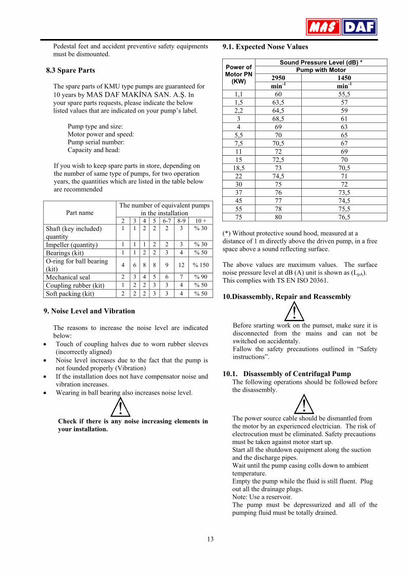
9.1. Expected Noıse Values
Sound Pressure Level (dB) * Pump with Motor
2950 1450 Power of Motor PN
(KW) min-1 min-1
1,1 60 55,5 1,5 63,5 57 2,2 64,5 59 3 68,5 61 4 69 63
5,5 70 65 7,5 70,5 67 11 72 69 15 72,5 70
18,5 73 70,5 22 74,5 71 30 75 72 37 76 73,5 45 77 74,5 55 78 75,5 75 80 76,5
(*) Without protective sound hood, measured at a distance of 1 m directly above the driven pump, in a free space above a sound reflecting surface. The above values are maximum values. The surface noise pressure level at dB (A) unit is shown as (LpA). This complies with TS EN ISO 20361. 10.Disassembly, Repair and Reassembly
Before srarting work on the pumset, make sure it is disconnected from the mains and can not be switched on accidentaly. Fallow the safety precautions outlined in “Safety instructions”.
10.1. Disassembly of Centrifugal Pump
The following operations should be followed before the disassembly.
The power source cable should be dismantled from the motor by an experienced electrician. The risk of electrocution must be eliminated. Safety precautions must be taken against motor start up. Start all the shutdown equipment along the suction and the discharge pipes. Wait until the pump casing colls down to ambient temperature. Empty the pump while the fluid is still fluent. Plug out all the drainage plugs. Note: Use a reservoir. The pump must be depressurized and all of the pumping fluid must be totally drained.

14
Hazardous material must be emptied, collected and eliminated in accordance to environmental regulations. If there is a pipe line it must be dismounted. All the manometers, manometer lines and fittings must be dismounted. Pedestal feet and accident preventive safety equipments must be dismounted.
• Close all valves in the suction and discharge lines,
drain the pump by the drain plug(260) . • Remove coupling guard and other safety guards. • If a Spacer Type Coupling is used between the pump
and the motor, there is no need to disconnect the motor, from the Baseplate. To take out the Spacer Part is enough.
• Thanks to “Back Pull Out Design”; the impeller, shaft
and other rotating parts being removable no need to disconnect the suction and delivery pipes.
• If to take out the complete pump is necessary, disconnect pump from the driver , suction and discharge pipes and detach the baseplate.
• Disconnect the casing nuts (360) and take out the
pump rotor assembly ( Impeller + Shaft + Bearing Housing + Bearings + Bearing Covers + Stuffing box etc.)
• Take out the pump coupling half from the shaft (60) using a pull-off device and remove the coupling key (211).
• Unscrew the impeller end nut (65) and take out the impeller (20) and impeller key (210). Use rust remover solvent during dismountling if necessary.
• Unscrew cover bolts (320) Dismantle back cover (12)
• For taking out the soft packing, pull out housing segment (230) and soft seal ring (53)
• Dismantle bearing cover (34) then pull out mechanical seal ring (231).
• Dismantle the ball bearing (200) , shaft (60) and rotating part of mechanical seal (250) together by using a suitable device. After this operation stationary part of mechanical seal and coupling side ball bearing keep there position.
• Dismantle ball bearing and mechanical seak housing (59) by using a suitable pull-off device. Do not use metal hammer for this operation.
10.2. Reassembly • Reassembly proceeds in reverse sequence to
disassembly as described in section F1. You may find the attached drawings useful.
• Coat the seats and screw connections with graphite, silicon or similar slippery substance before reassembly. If you can not find any of the above you may use oil instead (except the pumps for drinking water)
• Never use the old gaskets, make sure the new gaskets and o-rings are the same size as the old ones.
• Start mounting from the bearings. Place rotating part of mechanical seal together with seal ring (52) in its position on the shaft. Put ball bearing (200) on the shaft also.
• Mount back cover (12) to the bearing housing (30). • Place stationary part of mechanical seal on its
position on the Mechanical seal housing (59). And maunt this part to the bearing housing (30)
• Put the ball bearing and bearing cover to its place. • Put soft packing (240) , soft seal ring (53) and shaft
segment (240) in position.

15
• Mount impeller key (210) and impeller (20). Screw the impeller nut (65)
• Mount coupling key and coupling pump half. • Now reassembly of the rotor group is complated. • Finally mount rotor assembly to the volute casing. (In
the repair shop or on site.) • Make sure the gaskets and o-rings are evenly placed
without sliding and not damaged or not squezed at all. • Place the pump on the baseplate, couple the motor.
Connect suction and discharge pipes as well as auxiliary pipes. Take the unit into operation as it was indicated in section 7.
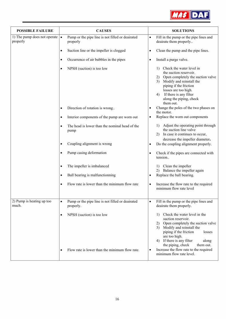
11. Possible Failures, Causes, Solutions
Possible failures and solution strategies are listed in the table below. Please apply to the Customers’ Service Department of our company when a generic solution is not found to your problem.
While the failures are repaired the pump must always be dry and un-pressurized.
16
POSSIBLE FAILURE CAUSES SOLUTIONS 1) The pump does not operate properly
• Pump or the pipe line is not filled or deairated properly
• Suction line or the impeller is clogged • Occurrence of air bubbles in the pipes • NPSH (suction) is too low • Direction of rotation is wrong.. • Interior components of the pump are worn out • The head is lower than the nominal head of the
pump • Coupling alignment is wrong • Pump casing deformation • The impeller is imbalanced • Ball bearing is malfunctionning • Flow rate is lower than the minimum flow rate
• Fill in the pump or the pipe lines and deairate them properly..
• Clean the pump and the pipe lines. • Install a purge valve.
1) Check the water level in the suction reservoir.
2) Open completely the suction valve 3) Modify and reinstall the
piping if the friction losses are too high.
4) If there is any filter along the piping, check them out.
• Change the poles of the two phases on the motor.
• Replace the worn out components
1) Adjust the operating point through the suction line valve
2) In case it continues to occur, decrease the impeller diameter.
• Do the coupling alignment properly. • Check if the pipes are connected with
tension..
1) Clean the impeller 2) Balance the impeller again
• Replace the ball bearing. • Increase the flow rate to the required
minimum flow rate level
2) Pump is heating up too much.
• Pump or the pipe line is not filled or deairated properly.
• NPSH (suction) is too low • Flow rate is lower than the minimum flow rate.
• Fill in the pump or the pipe lines and deairate them properly.
1) Check the water level in the
suction reservoir. 2) Open completely the suction valve 3) Modify and reinstall the
piping if the friction losses are too high.
4) If there is any filter along the piping, check them out.
• Increase the flow rate to the required minimum flow rate level.

17
Some other failures, which may occur apart from the failures mentioned above, are listed below:
CAUSES OF POSSIBLE FAILURE SOLUTIONS • Counter pressure is more than the design pressure • Rotation speed is too low • Density and viscosity is not the same with the one
chosen for pump operation. • Rotational speed too high. • Seal is harmed • Seal is not appropriate for the pumping fluid • The distance between coupling halves are wrong • Motor voltage is wrong • Motor operates at only two phases.
1) Open the discharge valve until it attains the operating point.
2) Install a larger diameter impeller. 3) Increase the rotational speed (turbine, frequency
control…) • Increase the rotational speed (turbine, frequency
control…) • Apply to our factory in case an incompatibility problem
occurs • Decrease the rotational speed (turbine, frequency
control…) • Check the seal. Replace it if necessary. • Wrong seal is in usage. Replace it with the correct one. • Adjust the distance according to the technical drawing. • Use the correct motor.
1) Check the cable connections 2) Change the fuses..

18
12. PUMP DIMENSIONS TABLE AND WEIGHTS
Flange (PN16)
Length (mm)
Height (mm)
Pump Feet (mm) Fixing Details (mm)
Shaft End (mm) ( * )
No
Pump Type DN
(Suction) DN (Discharge) a f h1 h2 b m1 m2 n1 n2 s1(ø) W d(ø) l X
1 32–160 50 32 80 385 132 160 50 100 70 240 190 M12 285 24 50 65
2 32–200 50 32 80 385 160 180 50 100 70 240 190 M12 285 24 50 65
3 32–250 50 32 100 500 180 225 65 125 95 320 250 M12 370 32 80 80
4 40–160 65 40 80 385 132 160 50 100 70 240 190 M12 285 24 50 75
5 40–200 65 40 100 385 160 180 50 100 70 265 212 M12 285 24 50 75
6 40–250 65 40 100 500 180 225 65 125 95 320 250 M12 370 32 80 75
7 50–160 65 50 100 385 160 180 50 100 70 265 212 M12 285 24 50 80
8 50–200 65 50 100 385 160 200 50 100 70 265 212 M12 285 24 50 85
9 50–250 65 50 100 500 180 225 65 125 95 320 250 M12 370 32 80 85
10 65–160 80 65 100 500 160 200 65 125 95 280 212 M12 370 32 80 100
11 65–200 80 65 100 500 180 225 65 125 95 320 250 M12 370 32 80 100
12 65–250 80 65 100 500 200 250 80 160 120 360 280 M16 370 32 80 100
13 80–160 100 80 125 500 180 225 65 125 95 320 250 M12 370 32 80 110
14 80–200 100 80 125 500 180 250 65 125 95 345 280 M12 370 32 80 110
15 80–250 100 80 125 500 200 280 80 160 120 400 315 M16 370 32 80 115
16 100–200 125 100 125 500 200 280 80 160 120 360 280 M16 370 32 80 120
17 100–250 125 100 140 500 225 280 80 160 120 400 315 M18 370 32 80 120
h1
n2n1
s1
h2
a fD Nd
x
l
dDN s
m 2
Wm 1

19
13. TIGHTENING TORQUES
Tightening Torque Max (Nm) Property Classes Thread Diameter
8.8 10.9 M4 3.0 4.4 M5 5.9 8.7 M6 10 15 M8 25 36
M10 49 72 M12 85 125 M14 135 200 M16 210 310 M18 300 430 M20 425 610 M22 580 820 M24 730 1050 M27 1100 1550 M30 1450 2100 M33 1970 2770 M36 2530 3560
14. FORCES AND MOMENTS AT THE PUMP FLANGES
All of the applied loads if not reached the maximum allowable value, to provide that the following Additional conditions, one of these loads may exceed the normal limit: Any component of a force or a moment, must be limited 1.4 times of the maximum allowablevalue, The actual forces and moments acting on each flange, should provide the following formula:
22
allowable maximum
actual
2
allowable maximum
actual ≤⎟⎟⎠
⎞⎜⎜⎝
⎛+⎟
⎟⎠
⎞⎜⎜⎝
⎛
∑∑
∑∑
MM
FF
In here, ∑Fand ∑ M
are arithmetic sum of the loads for each flange at the pump level, without regard of the algebraic signs of the actual and maximum allowable values.

20
Forces Moments DN Flange Suction Flange Discharge Flange Suction Flange Discharge Flange Pump Type
Suction Discharge N N Nm Nm F y F z F x F y F z F x M y M z M x M y M z M x
32‐160 32‐200 32‐250
50 32 473 425 520 268 331 284 315 362 441 236 268 347
40‐160 40‐200 40‐250
65 40 583 536 662 315 394 347 347 378 473 284 331 410
50‐160 50‐200 50‐250
65 50 583 536 662 425 520 473 347 378 473 315 362 441
65‐160 65‐200 65‐250
80 65 709 646 788 536 662 583 362 410 504 347 378 473
80‐160 80‐200 80‐250
100 80 945 851 1055 646 788 709 362 410 504 362 410 504
100‐200 100‐250
125 100 1118 1008 1244 851 1055 945 394 457 551 394 457 551
Forces at the pump flanges were calculated according to TS EN ISO 5199 standard. The calculations are valid for the materials of cast iron and bronze. Forces and moments at the flanges that made of stainless material will be approximately twice as moments in the table.
15.TYPICAL PIPING
7
568
Figure 10 Typical Piping
1. SUCTION COLLECTOR 2. SUCTION VALVE 3. FILTER 4. PUMP 5. GASKET 6. MANOMETER 7. DISCHARGE
COLLECTOR 8. DISCHARGE VALVE
21
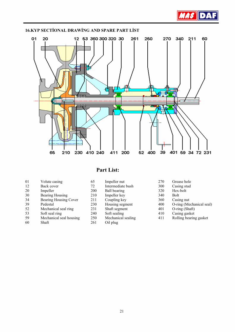
16.KYP SECTİONAL DRAWİNG AND SPARE PART LİST
Part List:
01 Volute casing 65 Impeller nut 270 Grease hole 12 Back cover 72 Intermediate bush 300 Casing stud 20 Impeller 200 Ball bearing 320 Hex-bolt 30 Bearing Housing 210 Impeller key 340 Bolt 34 Bearing Housing Cover 211 Coupling key 360 Casing nut 39 Pedestal 230 Housing segment 400 O-ring (Mechanical seal) 52 Mechanical seal ring 231 Shaft segment 401 O-ring (Shaft) 53 Soft seal ring 240 Soft sealing 410 Casing gasket 59 Mechanical seal housing 250 Mechanical sealing 411 Rolling bearing gasket 60 Shaft 261 Oil plug
22
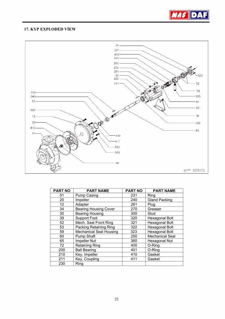
17. KYP EXPLODED VİEW
PART NO PART NAME PART NO PART NAME 01 Pump Casing 231 Ring 20 Impeller 240 Gland Packing 12 Adapter 261 Plug 34 Bearing Housing Cover 270 Greaser 30 Bearing Housing 300 Stud 39 Support Foot 320 Hexagonal Bolt 52 Mech. Seal Front Ring 321 Hexagonal Bolt 53 Packing Retaining Ring 322 Hexagonal Bolt 59 Mechanical Seal Housing 323 Hexagonal Bolt 60 Pump Shaft 250 Mechanical Seal 65 Impeller Nut 360 Hexagonal Nut 72 Retaining Ring 400 O-Ring 200 Ball Bearing 401 O-Ring 210 Key, Impeller 410 Gasket 211 Key, Coupling 411 Gasket 230 Ring