Embed Size (px)
Citation preview
Thermal Oil / Hot Water Pump
HPK-E/EX/EY/E4/S/SX/SY
Bearing Assemblies P02as to P08s
Installation/OperatingManual

Installation/Operating Manual HPK-E/EX/EY/E4/S/SX/SYOriginal operating manual KSB Aktiengesellschaft All rights reserved. Contents provided herein must neither be distributed, copied, reproduced,processed for any other purpose, nor otherwise transmitted to a third party without KSB´s expresswritten consent. Subject to technical modification without prior notice. © KSB Aktiengesellschaft Frankenthal 09.02.2010
Contents
Glossary ................................................................................................ 6
1 General ................................................................................................ 7
1.1 Principles .......................................................................................................... 7
1.2 Installation of partly completed machinery .................................................. 7
1.3 Target group ................................................................................................... 7
1.4 Other applicable documents .......................................................................... 7
1.5 Symbols ............................................................................................................ 7
2 Safety ................................................................................................... 9
2.1 Key to safety symbols/markings ..................................................................... 9
2.2 General ............................................................................................................ 9
2.3 Intended use .................................................................................................... 9
2.4 Personnel qualification and training ........................................................... 10
2.5 Consequences and risks caused by non-compliance with these operatinginstructions .................................................................................................... 10
2.6 Safety awareness ........................................................................................... 10
2.7 Safety information for the operator/user .................................................... 11
2.8 Safety information for maintenance, inspection and installation work ... 11
2.9 Unauthorised modes of operation ............................................................... 11
2.10 Explosion protection ..................................................................................... 11
2.10.1 Marking ......................................................................................................... 12
2.10.2 Temperature limits ........................................................................................ 12
2.10.3 Monitoring equipment ................................................................................. 12
2.10.4 Operating limits ............................................................................................ 13
3 Transport/Temporary Storage/Disposal ........................................... 14
3.1 Transport ....................................................................................................... 14
3.2 Storage and preservation ............................................................................. 14
4 Description of the Pump (Set) .......................................................... 16
4.1 General description ....................................................................................... 16
4.2 Designation ................................................................................................... 16
4.3 Name plate .................................................................................................... 16
4.4 Design details ................................................................................................ 16
4.5 Configuration and function ......................................................................... 20
4.6 Noise characteristics ..................................................................................... 21
4.7 Scope of supply ............................................................................................. 21
4.8 Dimensions and weights ............................................................................... 22
5 Installation at Site ............................................................................. 23
5.1 Safety regulations ......................................................................................... 23
5.2 Checking the site before installation ........................................................... 23
Contents
HPK-E/EX/EY/E4/S/SX/SY 3 of 72
5.3 Installing the pump set ................................................................................. 23
5.3.1 Installation on the foundation ..................................................................... 23
5.3.2 Installation without foundation .................................................................. 24
5.4 Piping ............................................................................................................. 25
5.4.1 Connecting the piping .................................................................................. 25
5.4.2 Permissible forces and moments at the pump nozzles ............................... 26
5.4.3 Auxiliary connections .................................................................................... 28
5.5 Protective equipment ................................................................................... 29
5.6 Checking the coupling alignment ................................................................ 29
5.7 Aligning the pump and motor ..................................................................... 30
5.7.1 Motors with levelling screw ......................................................................... 30
5.7.2 Motors without levelling screw .................................................................... 31
5.8 Electrical connection ..................................................................................... 32
5.8.1 Setting the time relay ................................................................................... 32
5.8.2 Connecting the motor .................................................................................. 32
5.9 Checking the direction of rotation .............................................................. 33
6 Commissioning/Start-up/Shutdown ................................................. 34
6.1 Commissioning/start-up ................................................................................ 34
6.1.1 Prerequisites for commissioning/start-up .................................................... 34
6.1.2 Filling in lubricants ........................................................................................ 34
6.1.3 Shaft seal ....................................................................................................... 35
6.1.4 Priming and venting the pump .................................................................... 36
6.1.5 Water cooling ................................................................................................ 37
6.1.6 Cooling of the shaft seal ............................................................................... 37
6.1.7 Bearing bracket cooling ................................................................................ 38
6.1.8 Cooling of the heat exchanger .................................................................... 38
6.1.9 Heating up/keeping warm the pump (set) .................................................. 38
6.1.10 Final check ..................................................................................................... 38
6.1.11 Start-up .......................................................................................................... 39
6.1.12 Checking the shaft seal ................................................................................. 40
6.1.13 Shutdown ...................................................................................................... 40
6.2 Operating limits ............................................................................................ 41
6.2.1 Ambient temperature ................................................................................... 41
6.2.2 Frequency of starts ........................................................................................ 42
6.2.3 Flow rate ........................................................................................................ 42
6.2.4 Density of the fluid handled ........................................................................ 43
6.2.5 Abrasive fluids ............................................................................................... 43
6.3 Shutdown/storage/preservation ................................................................... 43
6.3.1 Measures to be taken for shutdown ............................................................ 43
6.4 Returning to service after storage ............................................................... 43
7 Servicing/Maintenance ...................................................................... 45
7.1 Safety regulations ......................................................................................... 45
7.2 Servicing/inspection ...................................................................................... 45
7.2.1 Supervision of operation .............................................................................. 45
Contents
4 of 72 HPK-E/EX/EY/E4/S/SX/SY
7.2.2 Inspection work ............................................................................................. 47
7.2.3 Lubrication and lubricant change of rolling element bearings ................. 48
7.3 Drainage/disposal .......................................................................................... 49
7.4 Dismantling the pump set ............................................................................ 50
7.4.1 General notes/Safety regulations ................................................................. 50
7.4.2 Preparing the pump set ................................................................................ 50
7.4.3 Dismantling the motor ................................................................................. 50
7.4.4 Removing the back pull-out unit ................................................................. 51
7.4.5 Removing the impeller ................................................................................. 51
7.4.6 Dismantling the shaft seal ............................................................................ 51
7.4.7 Dismantling the bearings ............................................................................. 52
7.5 Reassembling the pump set .......................................................................... 52
7.5.1 General notes/Safety regulations ................................................................. 52
7.5.2 Installing the bearings .................................................................................. 53
7.5.3 Installing the shaft seal ................................................................................. 54
7.5.4 Fitting the impeller ....................................................................................... 56
7.5.5 Fitting the back pull-out unit ....................................................................... 57
7.5.6 Mounting the motor .................................................................................... 57
7.6 Tightening torques ....................................................................................... 57
7.6.1 Tightening torques for volute casing/bearing bracket bolts ...................... 57
7.6.2 Tightening torques for the impeller nut ..................................................... 58
7.7 Spare parts stock ........................................................................................... 58
7.7.1 Ordering spare parts ..................................................................................... 58
7.7.2 Recommended spare parts stock for 2 years' operation to DIN 24296 ...... 58
7.7.3 Interchangeability of pump components .................................................... 59
8 Trouble-shooting ............................................................................... 61
9 Related Documents ........................................................................... 63
9.1 General assembly drawing with list of components ................................... 63
9.2 Gland packing version .................................................................................. 66
10 EC Declaration of Conformity .......................................................... 67
11 Certificate of Decontamination ....................................................... 68
Index .................................................................................................. 69
Contents
HPK-E/EX/EY/E4/S/SX/SY 5 of 72
Glossary
Back pull-out designThe complete back pull-out unit can be pulledout without having to remove the pump casingfrom the piping.
Back pull-out unitPump without pump casing; partly completedmachinery
Certificate of decontaminationA certificate of decontamination certifies thatthe pump (set) has been properly drained toeliminate any environmental and healthhazards arising from components in contactwith the fluid handled.
Discharge lineThe line which is connected to the dischargenozzle
Hydraulic systemThe part of the pump in which the kineticenergy is converted into pressure energy
Pool of pumpsPumps which are purchased and storedindependently of their later use
PumpMachine without drive, additional componentsor accessories
Pump setComplete pump set consisting of pump, drive,additional components and accessories
Suction lift line/suction head lineThe line which is connected to the suctionnozzle
Glossary
6 of 72 HPK-E/EX/EY/E4/S/SX/SY
1 General
1.1 Principles
This manual is supplied as an integral part of the type series and variants indicatedon the front cover. This manual describes the proper and safe use of this equipmentin all phases of operation.
The name plate indicates the type series and size, the main operating data, the ordernumber and the order item number. The order number and order item number clearly identify the pump (set) and serve as identification for all further businessprocesses.
In the event of damage, immediately contact your nearest KSB Service centre tomaintain the right to claim under warranty.
Noise characteristics (⇨ Section 4.6 Page 21)
1.2 Installation of partly completed machinery
To install partly completed machinery supplied by KSB, please refer to the sub-sections under Servicing/Maintenance. (⇨ Section 7.5.5 Page 57)
1.3 Target group
This manual is aimed at the target group of trained and qualified specialist technicalpersonnel. (⇨ Section 2.4 Page 10)
1.4 Other applicable documents
Table 1: Overview of other applicable documents
Document ContentsData sheet Description of the technical data of the pump
(set)General arrangement drawing/Outline drawing
Description of mating and installation dimensionsfor the pump (set)
Drawing of auxiliary connections Description of auxiliary connectionsHydraulic characteristic curve Characteristic curves showing head, NPSH
required, efficiency and power inputGeneral assembly drawing1) Sectional drawing of the pump
Sub-supplier product literature1) Operating manuals and other product literatureof accessories and integrated machinerycomponents
Spare parts lists1) Description of spare parts
Piping layout1) Description of auxiliary piping
List of components1) Description of all pump components
1.5 Symbols
Table 2: Symbols used in this manual
Symbol Description✓ Conditions which need to be fulfilled before proceeding with the
step-by-step instructions⊳ Safety instructions⇨ Result of an action⇨ Cross-references
1) If agreed to be included in the scope of supply
1 General
HPK-E/EX/EY/E4/S/SX/SY 7 of 72
Symbol Description1.
2.
Step-by-step instructions
NoteRecommendations and important information on how to handlethe product
1 General
8 of 72 HPK-E/EX/EY/E4/S/SX/SY
2 SafetyAll the information contained in this section refers to hazardous situations.
2.1 Key to safety symbols/markings
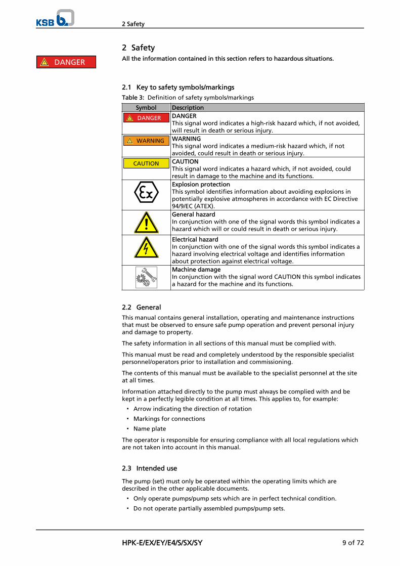
Table 3: Definition of safety symbols/markings
Symbol Description
! DANGER DANGERThis signal word indicates a high-risk hazard which, if not avoided,will result in death or serious injury.
! WARNING WARNINGThis signal word indicates a medium-risk hazard which, if notavoided, could result in death or serious injury.
CAUTION CAUTIONThis signal word indicates a hazard which, if not avoided, couldresult in damage to the machine and its functions.Explosion protectionThis symbol identifies information about avoiding explosions inpotentially explosive atmospheres in accordance with EC Directive94/9/EC (ATEX).General hazardIn conjunction with one of the signal words this symbol indicates ahazard which will or could result in death or serious injury.
Electrical hazardIn conjunction with one of the signal words this symbol indicates ahazard involving electrical voltage and identifies informationabout protection against electrical voltage.Machine damage In conjunction with the signal word CAUTION this symbol indicatesa hazard for the machine and its functions.
2.2 General
This manual contains general installation, operating and maintenance instructionsthat must be observed to ensure safe pump operation and prevent personal injuryand damage to property.
The safety information in all sections of this manual must be complied with.
This manual must be read and completely understood by the responsible specialistpersonnel/operators prior to installation and commissioning.
The contents of this manual must be available to the specialist personnel at the siteat all times.
Information attached directly to the pump must always be complied with and bekept in a perfectly legible condition at all times. This applies to, for example:
▪ Arrow indicating the direction of rotation
▪ Markings for connections
▪ Name plate
The operator is responsible for ensuring compliance with all local regulations whichare not taken into account in this manual.
2.3 Intended use
The pump (set) must only be operated within the operating limits which aredescribed in the other applicable documents.
▪ Only operate pumps/pump sets which are in perfect technical condition.
▪ Do not operate partially assembled pumps/pump sets.
! DANGER
2 Safety
HPK-E/EX/EY/E4/S/SX/SY 9 of 72
▪ Only use the pump to handle the fluids specified in the data sheet or productliterature of the respective design variant.
▪ Never operate the pump without the fluid to be handled.
▪ Observe the minimum flow rates indicated in the data sheet or product literature(to prevent overheating, bearing damage, etc).
▪ Observe the maximum flow rates indicated in the data sheet or productliterature (to prevent overheating, mechanical seal damage, cavitation damage,bearing damage, etc).
▪ Do not throttle the flow rate on the suction side of the pump (to preventcavitation damage).
▪ Consult the manufacturer about any use or mode of operation not described inthe data sheet or product literature.
Prevention of foreseeable misuse
▪ Never open discharge-side shut-off elements further than permitted.
– The maximum flow rate specified in the data sheet or product literaturewould be exceeded.
– Risk of cavitation damage
▪ Never exceed the permissible operating limits specified in the data sheet orproduct literature regarding pressure, temperature, etc.
▪ Observe all safety information and instructions in this manual.
2.4 Personnel qualification and training
All personnel involved must be fully qualified to install, operate, maintain andinspect the machinery this manual refers to.
The responsibilities, competence and supervision of all personnel involved ininstallation, operation, maintenance and inspection must be clearly defined by theoperator.
Deficits in knowledge must be rectified by sufficiently trained specialist personneltraining and instructing the personnel who will carry out the respective tasks. Ifrequired, the operator can commission the manufacturer/supplier to train thepersonnel.
Training on the pump (set) must always be supervised by technical specialistpersonnel.
2.5 Consequences and risks caused by non-compliance with these operatinginstructions
▪ Non-compliance with these operating instructions will lead to forfeiture ofwarranty cover and of any and all rights to claims for damages.
▪ Non-compliance can, for example, have the following consequences:
– Hazards to persons due to electrical, thermal, mechanical and chemicaleffects and explosions
– Failure of important product functions
– Failure of prescribed maintenance and servicing practices
– Hazard to the environment due to leakage of hazardous substances
2.6 Safety awareness
In addition to the safety information contained in this manual and the intended use,the following safety regulations shall be complied with:
▪ Accident prevention, health and safety regulations
▪ Explosion protection regulations
▪ Safety regulations for handling hazardous substances
▪ Applicable standards and laws
2 Safety
10 of 72 HPK-E/EX/EY/E4/S/SX/SY
2.7 Safety information for the operator/user
▪ The operator shall fit contact guards for hot, cold or moving parts and check thatthe guards function properly.
▪ Do not remove the contact guard while the pump is running.
▪ Connect an earth conductor to the metal jacket if the fluid handled iselectrostatically charged.
▪ Provide the personnel with protective equipment and make sure it is used.
▪ Contain leakages (e.g at the shaft seal) of hazardous fluids handled (e.g.explosive, toxic, hot) so as to avoid any danger to persons and the environment.Adhere to all relevant laws.
▪ Eliminate all electrical hazards. (In this respect refer to the applicable nationalsafety regulations and/or regulations issued by the local energy supplycompanies.)
2.8 Safety information for maintenance, inspection and installation work
▪ Modifications or alterations of the pump are only permitted with themanufacturer's prior consent.
▪ Use only original spare parts or parts authorised by the manufacturer. The use ofother parts can invalidate any liability of the manufacturer for consequentialdamage.
▪ The operator ensures that all maintenance, inspection and installation work isperformed by authorised, qualified specialist personnel who are thoroughlyfamiliar with the manual.
▪ Carry out work on the pump (set) during standstill only.
▪ The pump casing must have cooled down to ambient temperature.
▪ Pump pressure must have been released and the pump must have been drained.
▪ When taking the pump set out of service always adhere to the proceduredescribed in the manual. (⇨ Section 6.1.13 Page 40)
▪ Decontaminate pumps which handle fluids posing a health hazard. (⇨ Section 7.3Page 49)
▪ As soon as the work is completed, re-install and/or re-activate any safety-relevantand protective devices. Before returning the product to service, observe allinstructions on commissioning. (⇨ Section 6.1 Page 34)
2.9 Unauthorised modes of operation
Never operate the pump (set) outside the limits stated in the data sheet and in thismanual.
The warranty relating to the operating reliability and safety of the supplied pump(set) is only valid if the equipment is used in accordance with its intended use. (⇨Section 2.3 Page 9)
2.10 Explosion protection
Always observe the information on explosion protection given in this section whenoperating the pump in potentially explosive atmospheres.
Only pumps/pump sets marked as explosion-proof and identified as such in the datasheet may be used in potentially explosive atmospheres.
Special conditions apply to the operation of explosion-proof pump sets to ECDirective 94/9/EC (ATEX). Especially adhere to the sections in this manual marked with the Ex symbol and thefollowing sections (⇨ Section 2.10.1 Page 12) to (⇨ Section 2.10.4 Page 13). The explosion-proof status of the pump set is only assured if the pump set is used inaccordance with its intended use. Never operate the pump (set) outside the limits stated in the data sheet and on the
! DANGER
2 Safety
HPK-E/EX/EY/E4/S/SX/SY 11 of 72
name plate.Prevent impermissible modes of operation at all times.
2.10.1 Marking
The marking on the pump refers to the pump only. Example of such marking: II 2 G c TX Refer to the Temperature limits table for the temperatures permitted for theindividual pump variants. (⇨ Section 2.10.2 Page 12)
An EC manufacturer's declaration is required for the shaft coupling; the shaftcoupling must be marked accordingly.
The motor must be considered separately.
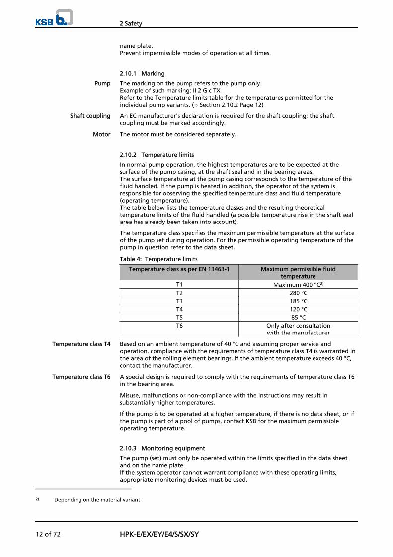
2.10.2 Temperature limits
In normal pump operation, the highest temperatures are to be expected at thesurface of the pump casing, at the shaft seal and in the bearing areas. The surface temperature at the pump casing corresponds to the temperature of thefluid handled. If the pump is heated in addition, the operator of the system isresponsible for observing the specified temperature class and fluid temperature(operating temperature).The table below lists the temperature classes and the resulting theoreticaltemperature limits of the fluid handled (a possible temperature rise in the shaft sealarea has already been taken into account).
The temperature class specifies the maximum permissible temperature at the surfaceof the pump set during operation. For the permissible operating temperature of thepump in question refer to the data sheet.
Table 4: Temperature limits
Temperature class as per EN 13463-1 Maximum permissible fluidtemperature
T1 Maximum 400 °C2)
T2 280 °CT3 185 °CT4 120 °CT5 85 °CT6 Only after consultation
with the manufacturer
Based on an ambient temperature of 40 °C and assuming proper service andoperation, compliance with the requirements of temperature class T4 is warranted inthe area of the rolling element bearings. If the ambient temperature exceeds 40 °C,contact the manufacturer.
A special design is required to comply with the requirements of temperature class T6in the bearing area.
Misuse, malfunctions or non-compliance with the instructions may result insubstantially higher temperatures.
If the pump is to be operated at a higher temperature, if there is no data sheet, or ifthe pump is part of a pool of pumps, contact KSB for the maximum permissibleoperating temperature.
2.10.3 Monitoring equipment
The pump (set) must only be operated within the limits specified in the data sheetand on the name plate. If the system operator cannot warrant compliance with these operating limits,appropriate monitoring devices must be used.
Pump
Shaft coupling
Motor
Temperature class T4
Temperature class T6
2) Depending on the material variant.
2 Safety
12 of 72 HPK-E/EX/EY/E4/S/SX/SY
Check whether monitoring equipment is required to ensure that the pump setfunctions properly.
Contact KSB for further information on monitoring equipment.
2.10.4 Operating limits
The minimum flows indicated in (⇨ Section 6.2.3 Page 42) refer to water and water-like fluids. Longer operating periods with these fluids and at the flow rates indicatedwill not cause an additional increase in the temperatures on the pump surface.However, if the physical properties of the fluids handled are different from water, itis essential to check whether an additional heat build-up may occur and if theminimum flow rate must therefore be increased. The calculation formula in (⇨Section 6.2.3 Page 42) can be used to check whether an additional heat build-upmay lead to a hazardous temperature increase at the pump surface.
2 Safety
HPK-E/EX/EY/E4/S/SX/SY 13 of 72
3 Transport/Temporary Storage/Disposal
3.1 Transport
DANGERThe pump (set) could slip out of the suspension arrangementDanger to life from falling parts!
▷ Always transport the pump (set) in horizontal position.
▷ Never attach the suspension arrangement to the free shaft end or the motoreyebolt.
▷ Refer to the weights given in the general arrangement drawing.
▷ Observe the local accident prevention regulations.
▷ Use suitable, permitted lifting tackle, e.g. self-tightening lifting tongs.
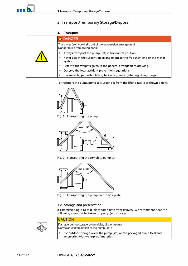
To transport the pump/pump set suspend it from the lifting tackle as shown below.
Fig. 1: Transporting the pump
max. 90 °
Fig. 2: Transporting the complete pump set
max. 90 °
Fig. 3: Transporting the pump on the baseplate
3.2 Storage and preservation
If commissioning is to take place some time after delivery, we recommend that thefollowing measures be taken for pump (set) storage.
CAUTIONDamage during storage by humidity, dirt, or verminCorrosion/contamination of the pump (set)!
▷ For outdoor storage cover the pump (set) or the packaged pump (set) andaccessories with waterproof material.
3 Transport/Temporary Storage/Disposal
14 of 72 HPK-E/EX/EY/E4/S/SX/SY
CAUTIONWet, contaminated or damaged openings and connectionsLeakage or damage to the pump set!
▷ Only remove caps/covers from the openings of the pump set at the time ofinstallation.
Store the pump (set) in a dry, protected room where the atmospheric humidity is asconstant as possible.
Rotate the shaft by hand once a month, e.g. via the motor fan.
If properly stored indoors, the pump set is protected for a maximum of 12 months.New pumps/pump sets are supplied by our factory duly prepared for storage.
For storing a pump (set) which has already been operated, observe the relevantinstructions. (⇨ Section 6.3.1 Page 43)
3 Transport/Temporary Storage/Disposal
HPK-E/EX/EY/E4/S/SX/SY 15 of 72
4 Description of the Pump (Set)
4.1 General description
▪ Heat transfer liquid pump with shaft seal
Pump for handling hot water or organic heat transfer fluids in piping or tanksystems.
The HPK-E type series is type-tested to TRD (German Steam Boiler Regulations) byTÜV (German Association for Technical Supervision). (Special design)
4.2 Designation
Example: HPK SY F 80 - 160
Table 5: Key to the designation
Code DescriptionHPK Type seriesS Material of wetted components, e.g. nodular cast ironY Centreline pump feetF Additional code, e.g. F = off-standard flange design80 Nominal discharge nozzle diameter [mm]160 Nominal impeller diameter [mm]
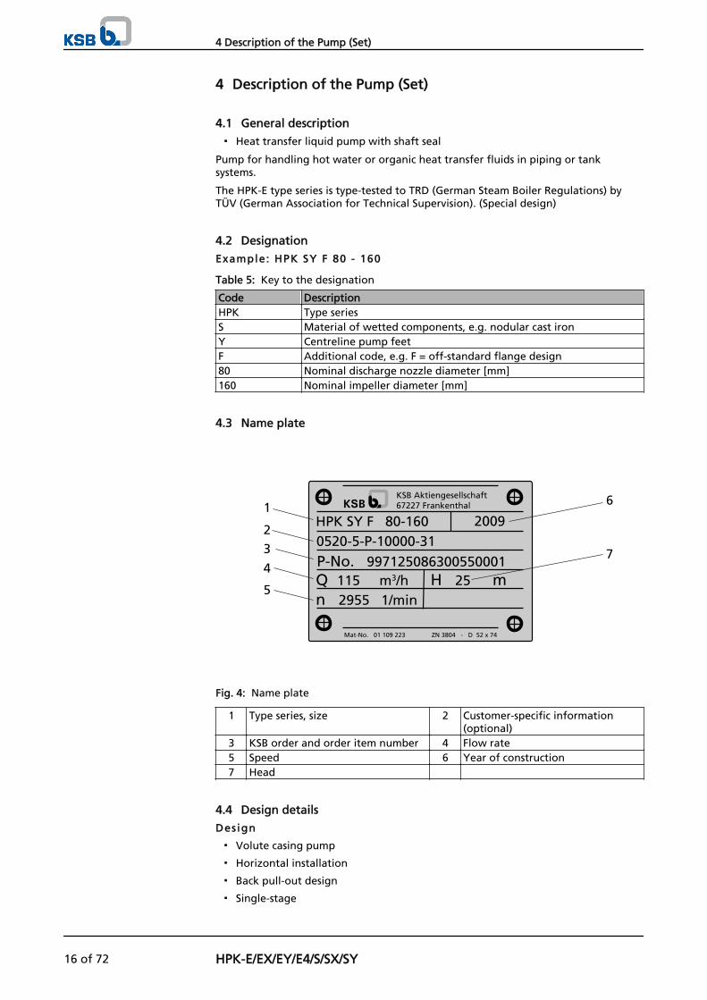
4.3 Name plate
HPK SY F 80-160
P-No. 997125086300550001Q 115 m3/h H 25 mn 2955 1/min
KSB Aktiengesellschaft67227 Frankenthal
Mat-No. 01 109 223 ZN 3804 - D 52 x 74
20090520-5-P-10000-31
1
2
5
4
3
6
7
Fig. 4: Name plate
1 Type series, size 2 Customer-specific information(optional)
3 KSB order and order item number 4 Flow rate5 Speed 6 Year of construction7 Head
4.4 Design details
Design
▪ Volute casing pump
▪ Horizontal installation
▪ Back pull-out design
▪ Single-stage
4 Description of the Pump (Set)
16 of 72 HPK-E/EX/EY/E4/S/SX/SY
▪ Meets technical requirements to ISO 5199
▪ Dimensions and ratings to EN 22 858/ISO 2858complemented by pumps of nominal diameters DN 25, DN 200 and above
Pump cas ing
▪ Single or double volute, depending on the pump size
▪ Radially split volute casing
▪ Volute casing with integrally cast pump feet
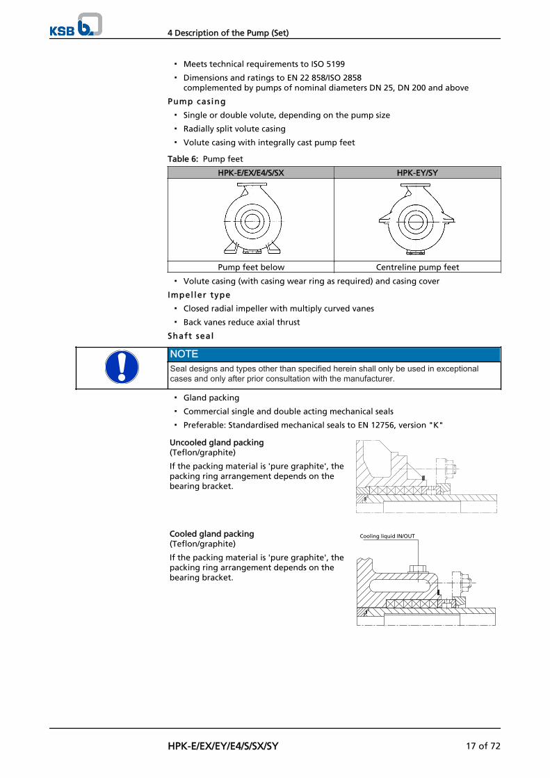
Table 6: Pump feet
HPK-E/EX/E4/S/SX HPK-EY/SY
Pump feet below Centreline pump feet
▪ Volute casing (with casing wear ring as required) and casing cover
Impel ler type
▪ Closed radial impeller with multiply curved vanes
▪ Back vanes reduce axial thrust
Shaft seal
NOTESeal designs and types other than specified herein shall only be used in exceptionalcases and only after prior consultation with the manufacturer.
▪ Gland packing
▪ Commercial single and double acting mechanical seals
▪ Preferable: Standardised mechanical seals to EN 12756, version "K"
Uncooled gland packing(Teflon/graphite)
If the packing material is 'pure graphite', thepacking ring arrangement depends on thebearing bracket.
Cooled gland packing(Teflon/graphite)
If the packing material is 'pure graphite', thepacking ring arrangement depends on thebearing bracket.
Cooling liquid IN/OUT
4 Description of the Pump (Set)
HPK-E/EX/EY/E4/S/SX/SY 17 of 72
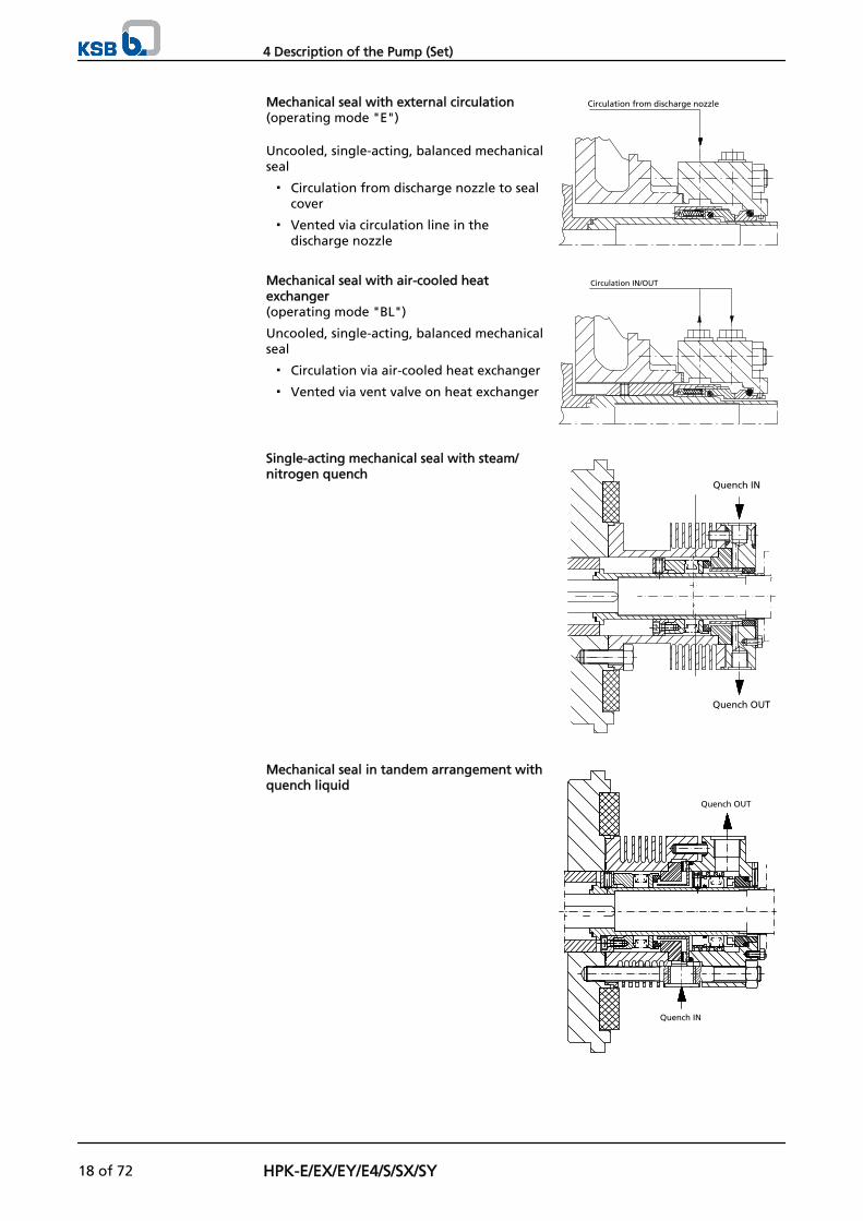
Mechanical seal with external circulation(operating mode "E")
Uncooled, single-acting, balanced mechanicalseal
▪ Circulation from discharge nozzle to sealcover
▪ Vented via circulation line in thedischarge nozzle
Circulation from discharge nozzle
Mechanical seal with air-cooled heatexchanger(operating mode "BL")
Uncooled, single-acting, balanced mechanicalseal
▪ Circulation via air-cooled heat exchanger
▪ Vented via vent valve on heat exchanger
Circulation IN/OUT
Single-acting mechanical seal with steam/nitrogen quench
Quench IN
Quench OUT
Mechanical seal in tandem arrangement withquench liquid
Quench IN
Quench OUT
4 Description of the Pump (Set)
18 of 72 HPK-E/EX/EY/E4/S/SX/SY
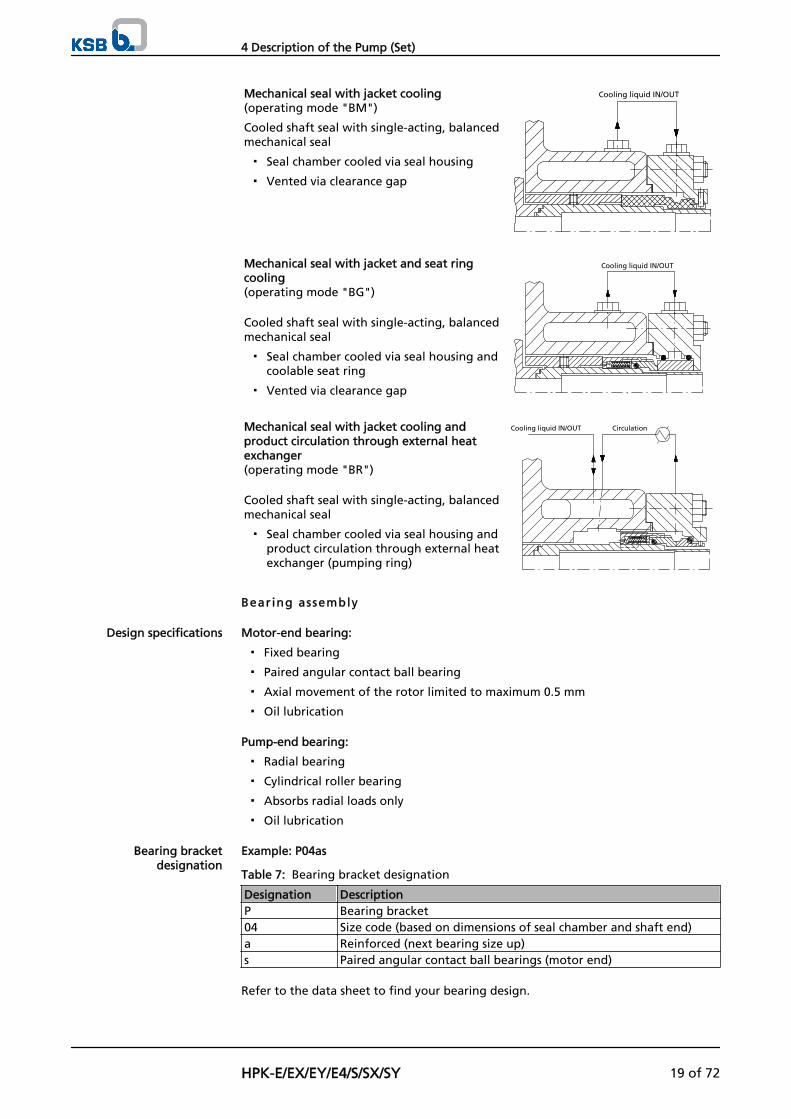
Mechanical seal with jacket cooling(operating mode "BM")
Cooled shaft seal with single-acting, balancedmechanical seal
▪ Seal chamber cooled via seal housing
▪ Vented via clearance gap
Cooling liquid IN/OUT
Mechanical seal with jacket and seat ringcooling(operating mode "BG")
Cooled shaft seal with single-acting, balancedmechanical seal
▪ Seal chamber cooled via seal housing andcoolable seat ring
▪ Vented via clearance gap
Cooling liquid IN/OUT
Mechanical seal with jacket cooling andproduct circulation through external heatexchanger(operating mode "BR")
Cooled shaft seal with single-acting, balancedmechanical seal
▪ Seal chamber cooled via seal housing andproduct circulation through external heatexchanger (pumping ring)
Cooling liquid IN/OUT Circulation
Bear ing assembly
Motor-end bearing:
▪ Fixed bearing
▪ Paired angular contact ball bearing
▪ Axial movement of the rotor limited to maximum 0.5 mm
▪ Oil lubrication
Pump-end bearing:
▪ Radial bearing
▪ Cylindrical roller bearing
▪ Absorbs radial loads only
▪ Oil lubrication
Example: P04as
Table 7: Bearing bracket designation
Designation DescriptionP Bearing bracket04 Size code (based on dimensions of seal chamber and shaft end)a Reinforced (next bearing size up)s Paired angular contact ball bearings (motor end)
Refer to the data sheet to find your bearing design.
Design specifications
Bearing bracketdesignation
4 Description of the Pump (Set)
HPK-E/EX/EY/E4/S/SX/SY 19 of 72
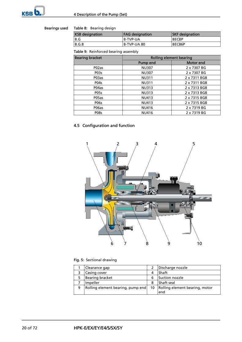
Table 8: Bearing design
KSB designation FAG designation SKF designationB.G B-TVP-UA BECBPB.G.8 B-TVP-UA 80 BEC86P
Table 9: Reinforced bearing assembly
Bearing bracket Rolling element bearingPump end Motor end
P02as NU307 2 x 7307 BGP03s NU307 2 x 7307 BG
P03as NU311 2 x 7311 BG8P04s NU311 2 x 7311 BG8P04as NU313 2 x 7313 BG8P05s NU313 2 x 7313 BG8P05as NU413 2 x 7315 BG8P06s NU413 2 x 7315 BG8P06as NU416 2 x 7319 BGP08s NU416 2 x 7319 BG
4.5 Configuration and function
1 2 3 4 5
6 7 8 9 10
Fig. 5: Sectional drawing
1 Clearance gap 2 Discharge nozzle3 Casing cover 4 Shaft5 Bearing bracket 6 Suction nozzle7 Impeller 8 Shaft seal9 Rolling element bearing, pump end 10 Rolling element bearing, motor
end
Bearings used
4 Description of the Pump (Set)
20 of 72 HPK-E/EX/EY/E4/S/SX/SY
The pump is designed with an axial fluid inlet and a radial or tangential outlet. Thehydraulic system runs in its own bearings and is connected to the motor by a shaftcoupling.
The fluid enters the pump axially via the suction nozzle (6) and is acceleratedoutward in a cylindrical flow by the rotating impeller (7). The flow profile of thepump casing converts the kinetic energy of the fluid into pressure energy. The fluid ispumped to the discharge nozzle (2), where it leaves the pump. The clearance gap (1)prevents any fluid from flowing back from the casing into the inlet. At the rear sideof the impeller, the shaft (4) enters the casing via the casing cover (3). The shaftpassage through the cover is sealed towards the atmosphere by a shaft seal (8). Theshaft runs in rolling element bearings (9 and 10), which are supported by a bearingbracket (5) linked with the pump casing and/or casing cover.
The pump is sealed by a shaft seal.Standardised mechanical seal or packed gland
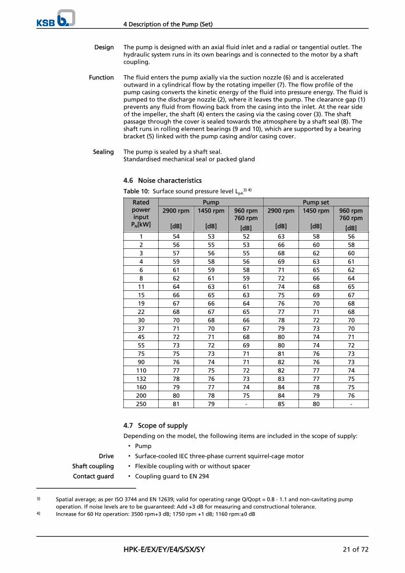
4.6 Noise characteristics
Table 10: Surface sound pressure level LpA3) 4)
Ratedpowerinput
PN[kW]
Pump Pump set2900 rpm
[dB]
1450 rpm
[dB]
960 rpm760 rpm
[dB]
2900 rpm
[dB]
1450 rpm
[dB]
960 rpm760 rpm
[dB]1 54 53 52 63 58 562 56 55 53 66 60 583 57 56 55 68 62 604 59 58 56 69 63 616 61 59 58 71 65 628 62 61 59 72 66 6411 64 63 61 74 68 6515 66 65 63 75 69 6719 67 66 64 76 70 6822 68 67 65 77 71 6830 70 68 66 78 72 7037 71 70 67 79 73 7045 72 71 68 80 74 7155 73 72 69 80 74 7275 75 73 71 81 76 7390 76 74 71 82 76 73110 77 75 72 82 77 74132 78 76 73 83 77 75160 79 77 74 84 78 75200 80 78 75 84 79 76250 81 79 - 85 80 -
4.7 Scope of supply
Depending on the model, the following items are included in the scope of supply:
▪ Pump
▪ Surface-cooled IEC three-phase current squirrel-cage motor
▪ Flexible coupling with or without spacer
▪ Coupling guard to EN 294
Design
Function
Sealing
Drive
Shaft coupling
Contact guard
3) Spatial average; as per ISO 3744 and EN 12639; valid for operating range Q/Qopt = 0.8 - 1.1 and non-cavitating pumpoperation. If noise levels are to be guaranteed: Add +3 dB for measuring and constructional tolerance.
4) Increase for 60 Hz operation: 3500 rpm+3 dB; 1750 rpm +1 dB; 1160 rpm:±0 dB
4 Description of the Pump (Set)
HPK-E/EX/EY/E4/S/SX/SY 21 of 72
▪ Baseplate (to ISO 3661), cast or welded, for pump and motor, in torsion-resistantdesign
▪ Channel section steel or folded steel plate
▪ As required
4.8 Dimensions and weights
For dimensions and weights please refer to the general arrangement drawing/outlinedrawing of the pump (set).
Baseplate
Special accessories
4 Description of the Pump (Set)
22 of 72 HPK-E/EX/EY/E4/S/SX/SY
5 Installation at Site
5.1 Safety regulations
DANGERImproper installation in potentially explosive atmospheresExplosion hazard!Damage to the pump set!
▷ Comply with the applicable local explosion protection regulations.
▷ Observe the information in the data sheet and on the name plates of pump andmotor.
5.2 Checking the site before installation
Place of instal lat ion
WARNINGInstallation on foundations which are unsecured and cannot support the loadPersonal injury and damage to property!
▷ Make sure the foundation concrete is of sufficient strength (min. X0 toDIN 1045).
▷ Only place the pump set on a foundation whose concrete has set firmly.
▷ Only place the pump set on a horizontal and level surface.
▷ Refer to the weights given in the general arrangement drawing.
1. Check the structural requirements. All structural work required must have been prepared in accordance with thedimensions stated in the outline drawing/general arrangement drawing.
5.3 Installing the pump set
Always install the pump set in horizontal position.
DANGERExcessive temperatures due to improper installationExplosion hazard!
▷ Install the pump in horizontal position to ensure self-venting of the pump.
5.3.1 Installation on the foundation
12
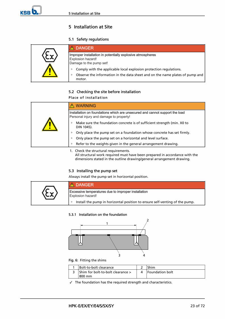
43Fig. 6: Fitting the shims
1 Bolt-to-bolt clearance 2 Shim3 Shim for bolt-to-bolt clearance >
800 mm4 Foundation bolt
✓ The foundation has the required strength and characteristics.
5 Installation at Site
HPK-E/EX/EY/E4/S/SX/SY 23 of 72
✓ The foundation has been prepared in accordance with the dimensions given inthe outline drawing/general arrangement drawing.
1. Position the pump set on the foundation and align it with the help of a spiritlevel placed on the shaft and discharge nozzle.Permissible deviation: 0.2 mm/m.
2. Use shims (2) for height compensation, if necessary. Always fit shims between the baseplate/foundation frame and the foundationitself; always insert them to the left and right of the foundation bolts (4) and inclose proximity to these bolts. For a bolt-to-bolt clearance > 800 mm, fit additional shims (3) halfway betweenthe adjoining holes. All shims must lie perfectly flush.
3. Insert the foundation bolts (4) into the holes provided.
4. Use concrete to set the foundation bolts (4) into the foundation.
5. Wait until the concrete has set firmly, then align the baseplate.
6. Tighten the foundation bolts (4) evenly and firmly.
7. Grout the baseplate using low-shrinkage concrete with a standard particle sizeand a water/cement ratio of ≤ 0.5.Produce flowability with the help of a solvent.Perform secondary treatment of the concrete to DIN 1045.
NOTEFor low-noise operation contact KSB to check whether the pump set can be installed onanti-vibration mounts.
NOTEExpansion joints can be fitted between pump and suction/discharge line.
5.3.2 Installation without foundation
4
1
2
3
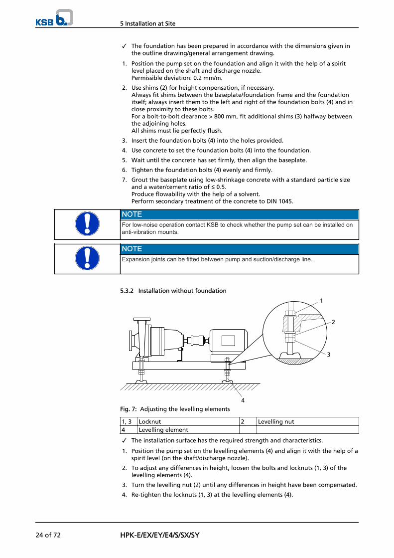
Fig. 7: Adjusting the levelling elements
1, 3 Locknut 2 Levelling nut4 Levelling element
✓ The installation surface has the required strength and characteristics.
1. Position the pump set on the levelling elements (4) and align it with the help of aspirit level (on the shaft/discharge nozzle).
2. To adjust any differences in height, loosen the bolts and locknuts (1, 3) of thelevelling elements (4).
3. Turn the levelling nut (2) until any differences in height have been compensated.
4. Re-tighten the locknuts (1, 3) at the levelling elements (4).
5 Installation at Site
24 of 72 HPK-E/EX/EY/E4/S/SX/SY
5.4 Piping
5.4.1 Connecting the piping
DANGERImpermissible loads acting on the pump nozzlesDanger to life from leakage of hot, toxic, corrosive or flammable fluids!
▷ Do not use the pump as an anchorage point for the piping.
▷ Anchor the pipelines in close proximity to the pump and connect them withouttransmitting any stresses or strains.
▷ Observe the permissible forces and moments at the pump nozzles.
▷ Take appropriate measures to compensate thermal expansion of the piping.
CAUTIONIncorrect earthing during welding work at the pipingDestruction of rolling element bearings (pitting effect)!
▷ Never earth the electric welding equipment on the pump or baseplate.
▷ Prevent current flowing through the rolling element bearings.
NOTEIt is recommended to install check and shut-off elements in the system, depending on thetype of plant and pump. However, such elements must not obstruct proper drainage orhinder disassembly of the pump.
✓ The suction lift line/suction head line has been laid with a rising/downward slopetowards the pump.
✓ The nominal diameters of the pipelines are at least equal to the nominaldiameters of the pump nozzles.
✓ To prevent excessive pressure losses, adapters to larger diameters have a diffuserangle of approximately 8°.
✓ The pipelines have been anchored in close proximity to the pump and connectedwithout transmitting any stresses or strains.
1. Thoroughly clean, flush and blow through all vessels, pipelines and connections(especially of new installations).
2. Before installing the pump in the piping, remove the flange covers on the suctionand discharge nozzles of the pump.
CAUTIONWelding beads, scale and other impurities in the pipingDamage to the pump!
▷ Free the piping from any impurities.
▷ If necessary, install a filter.
▷ Observe the instructions in (⇨ Section 7.2.2.3 Page 47).
3. If required, install a filter in the piping (see drawing: Filter in the piping).
5 Installation at Site
HPK-E/EX/EY/E4/S/SX/SY 25 of 72
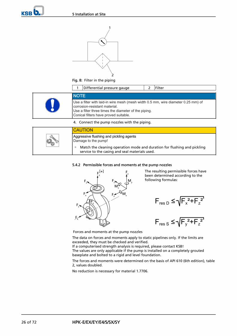
1
2Fig. 8: Filter in the piping
1 Differential pressure gauge 2 Filter
NOTEUse a filter with laid-in wire mesh (mesh width 0.5 mm, wire diameter 0.25 mm) ofcorrosion-resistant material.Use a filter three times the diameter of the piping.Conical filters have proved suitable.
4. Connect the pump nozzles with the piping.
CAUTIONAggressive flushing and pickling agentsDamage to the pump!
▷ Match the cleaning operation mode and duration for flushing and picklingservice to the casing and seal materials used.
5.4.2 Permissible forces and moments at the pump nozzles
[+]Fy
Fz
Fx
Fx
Fz
Fy
Fx
Fz
Fy
My
Mz
Mx
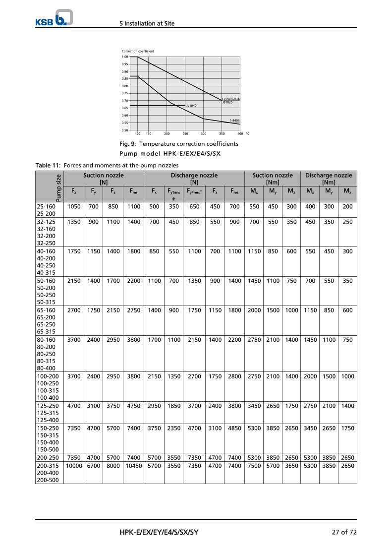
Forces and moments at the pump nozzles
The resulting permissible forces havebeen determined according to thefollowing formulas:
The data on forces and moments apply to static pipelines only. If the limits areexceeded, they must be checked and verified.If a computerised strength analysis is required, please contact KSB! The values are only applicable if the pump is installed on a completely groutedbaseplate and bolted to a rigid and level foundation.
The forces and moments were determined on the basis of API 610 (6th edition), table2, values doubled.
No reduction is necessary for material 1.7706.
5 Installation at Site
26 of 72 HPK-E/EX/EY/E4/S/SX/SY
1.00
0.75
0.80
0.85
0.90
0.95
0.50
0.55
0.60
0.65
0.70
400350300250200150120
JL1040
GP240GH+NJS1025
1.4408
°C
Correction coefficient
Fig. 9: Temperature correction coefficients
Pump model HPK-E/EX/E4/S /SX
Table 11: Forces and moments at the pump nozzles
Pum
p s
ize Suction nozzle
[N]Discharge nozzle
[N]Suction nozzle
[Nm]Discharge nozzle
[Nm]Fx Fy Fz Fres Fx FyTens
+FyPress- Fz Fres Mx My Mz Mx My Mz
25-160 25-200
1050 700 850 1100 500 350 650 450 700 550 450 300 400 300 200
32-12532-16032-20032-250
1350 900 1100 1400 700 450 850 550 900 700 550 350 450 350 250
40-16040-20040-25040-315
1750 1150 1400 1800 850 550 1100 700 1100 1150 850 600 550 450 300
50-16050-20050-25050-315
2150 1400 1700 2200 1100 700 1350 900 1400 1450 1100 750 700 550 350
65-16065-20065-25065-315
2700 1750 2150 2750 1400 900 1750 1150 1800 2000 1500 1000 1150 850 600
80-16080-20080-25080-31580-400
3700 2400 2950 3800 1700 1100 2150 1400 2200 2750 2100 1400 1450 1100 750
100-200100-250100-315100-400
3700 2400 2950 3800 2150 1350 2700 1750 2800 2750 2100 1400 2000 1500 1000
125-250125-315125-400
4700 3100 3750 4750 2950 1850 3700 2400 3800 3450 2650 1750 2750 2100 1400
150-250150-315150-400150-500
7350 4700 5700 7400 3750 2350 4700 3100 4850 5300 3850 2650 3450 2650 1750
200-250 7350 4700 5700 7400 5700 3550 7350 4700 7400 5300 3850 2650 5300 3850 2650200-315200-400200-500
10000 6700 8000 10450 5700 3550 7350 4700 7400 7500 5700 3650 5300 3850 2650
5 Installation at Site
HPK-E/EX/EY/E4/S/SX/SY 27 of 72
Pum
p s
ize Suction nozzle
[N]Discharge nozzle
[N]Suction nozzle
[Nm]Discharge nozzle
[Nm]Fx Fy Fz Fres Fx FyTens
+FyPress- Fz Fres Mx My Mz Mx My Mz
250-315250-400250-500
12000 8000 10000 12800 8000 5000 10000 6700 10450 9150 6900 4500 7500 5700 3650
300-400300-500
13350 8700 10700 13800 10000 6150 12000 8000 12800 9550 7150 4700 9150 6900 4500
350-400350-500
13350 8700 10700 13800 10700 6700 13350 8700 13800 9550 7150 4700 9550 7150 4700
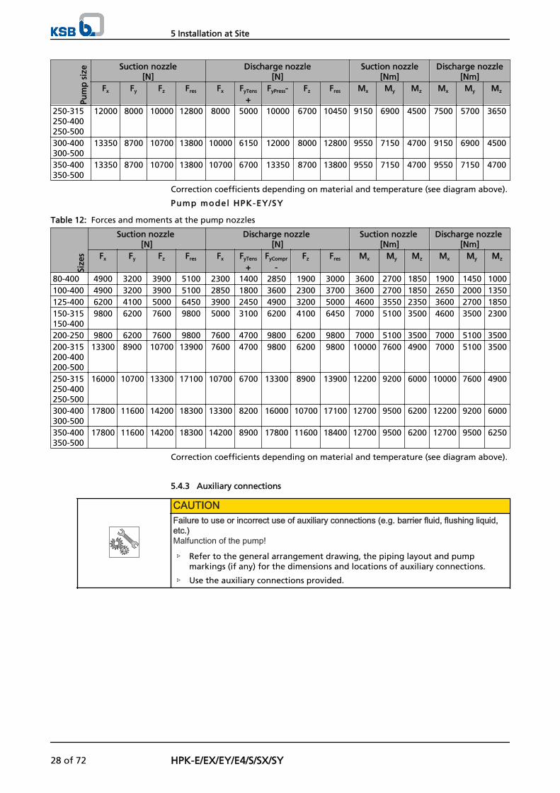
Correction coefficients depending on material and temperature (see diagram above).
Pump model HPK-EY/SY
Table 12: Forces and moments at the pump nozzles
Size
s
Suction nozzle [N]
Discharge nozzle [N]
Suction nozzle [Nm]
Discharge nozzle [Nm]
Fx Fy Fz Fres Fx FyTens
+FyCompr
-Fz Fres Mx My Mz Mx My Mz
80-400 4900 3200 3900 5100 2300 1400 2850 1900 3000 3600 2700 1850 1900 1450 1000100-400 4900 3200 3900 5100 2850 1800 3600 2300 3700 3600 2700 1850 2650 2000 1350125-400 6200 4100 5000 6450 3900 2450 4900 3200 5000 4600 3550 2350 3600 2700 1850150-315150-400
9800 6200 7600 9800 5000 3100 6200 4100 6450 7000 5100 3500 4600 3500 2300
200-250 9800 6200 7600 9800 7600 4700 9800 6200 9800 7000 5100 3500 7000 5100 3500200-315200-400200-500
13300 8900 10700 13900 7600 4700 9800 6200 9800 10000 7600 4900 7000 5100 3500
250-315250-400250-500
16000 10700 13300 17100 10700 6700 13300 8900 13900 12200 9200 6000 10000 7600 4900
300-400300-500
17800 11600 14200 18300 13300 8200 16000 10700 17100 12700 9500 6200 12200 9200 6000
350-400350-500
17800 11600 14200 18300 14200 8900 17800 11600 18400 12700 9500 6200 12700 9500 6250
Correction coefficients depending on material and temperature (see diagram above).
5.4.3 Auxiliary connections
CAUTIONFailure to use or incorrect use of auxiliary connections (e.g. barrier fluid, flushing liquid,etc.)Malfunction of the pump!
▷ Refer to the general arrangement drawing, the piping layout and pumpmarkings (if any) for the dimensions and locations of auxiliary connections.
▷ Use the auxiliary connections provided.
5 Installation at Site
28 of 72 HPK-E/EX/EY/E4/S/SX/SY
5.5 Protective equipment
DANGERRisk of potentially explosive atmoshere due to insufficient ventingExplosion hazard!
▷ Make sure the space between the casing cover/discharge cover and the bearingcover is sufficiently vented.
▷ Never close or cover the perforation of the bearing bracket guards (e.g. byinsulation).
WARNINGThe volute casing and casing/discharge cover take on the same temperature as the fluidhandledRisk of burning!
▷ Insulate the volute casing.
▷ Fit protective equipment.
CAUTIONHeat build-up in the bearing bracketDamage to the bearing!
▷ Never insulate the bearing bracket, bearing bracket lantern and casing cover.
5.6 Checking the coupling alignment
DANGERImpermissible temperatures at the coupling or bearings caused by misalignment of thecouplingExplosion hazard!
▷ Make sure that the coupling is correctly aligned at all times.
CAUTIONMisalignment of pump and motor shaftsDamage to pump, motor and coupling!
▷ Always check the coupling after the pump has been installed and connected tothe piping.
▷ Also check the coupling of pump sets supplied with pump and motor mountedon the same baseplate.
BA
A B
a) b)
B
B
A
A
1
1 2 21
1
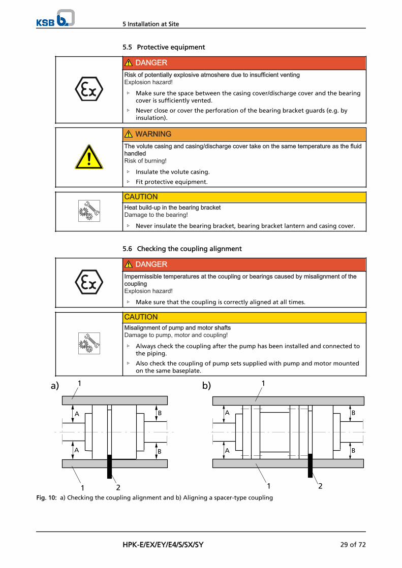
Fig. 10: a) Checking the coupling alignment and b) Aligning a spacer-type coupling
5 Installation at Site
HPK-E/EX/EY/E4/S/SX/SY 29 of 72
1 Straight-edge 2 Wedge gauge
✓ The coupling guard and step guard, if any, have been removed.
1. Loosen the support foot and re-tighten it without transmitting any stresses andstrains.
2. Place the straight-edge axially on both coupling halves.
3. Leave the straight-edge in this position and turn the coupling by hand. The coupling is correctly aligned if the distances A) and B) to the respective shaftsare the same at all points around the circumference.The radial and axial deviation of both coupling halves must not exceed 0.1 mmduring standstill as well as at operating temperature and under inlet pressure.
4. Check the distance between the two coupling halves around the circumference. The coupling is correctly aligned if the distance between the two coupling halvesis the same at all points around the circumference.The radial and axial deviation of both coupling halves must not exceed 0.1 mmduring standstill as well as at operating temperature and under inlet pressure.
5.7 Aligning the pump and motor
After having installed the pump set and connected the piping, check the couplingalignment and, if required, re-align the pump set (at the motor).
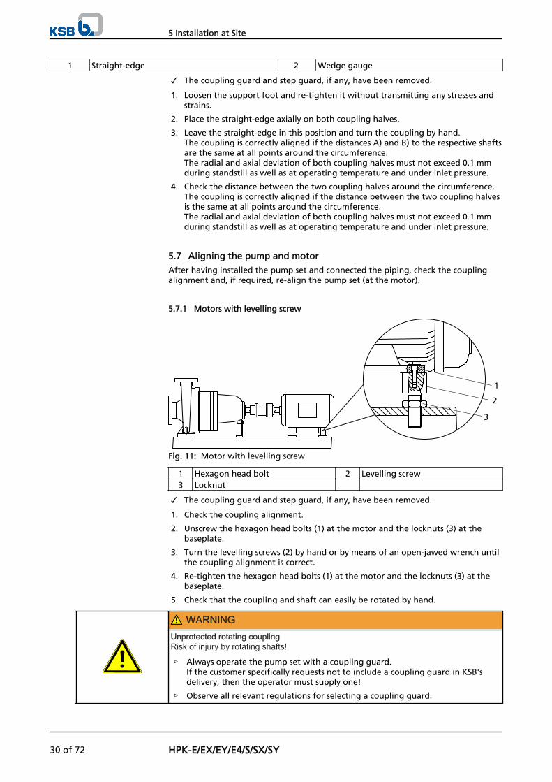
5.7.1 Motors with levelling screw
1
3
2
Fig. 11: Motor with levelling screw
1 Hexagon head bolt 2 Levelling screw3 Locknut
✓ The coupling guard and step guard, if any, have been removed.
1. Check the coupling alignment.
2. Unscrew the hexagon head bolts (1) at the motor and the locknuts (3) at thebaseplate.
3. Turn the levelling screws (2) by hand or by means of an open-jawed wrench untilthe coupling alignment is correct.
4. Re-tighten the hexagon head bolts (1) at the motor and the locknuts (3) at thebaseplate.
5. Check that the coupling and shaft can easily be rotated by hand.
WARNINGUnprotected rotating couplingRisk of injury by rotating shafts!
▷ Always operate the pump set with a coupling guard.If the customer specifically requests not to include a coupling guard in KSB'sdelivery, then the operator must supply one!
▷ Observe all relevant regulations for selecting a coupling guard.
5 Installation at Site
30 of 72 HPK-E/EX/EY/E4/S/SX/SY

DANGERRisk of ignition by frictional sparksExplosion hazard!
▷ Choose a coupling guard material that is non-sparking in the event ofmechanical contact (see DIN EN 13463-1).
6. Re-install the coupling guard and step guard, if any.
7. Check the distance between coupling and coupling guard.The coupling guard must not touch the coupling.
5.7.2 Motors without levelling screw
Any differences in the centre heights of the pump and motor shafts are compensatedby means of shims.
1Fig. 12: Pump set with shim
1 Shim
✓ The coupling guard and step guard, if any, have been removed.
1. Check the coupling alignment.
2. Unscrew the hexagon head bolts at the motor.
3. Insert shims underneath the motor feet until the difference in shaft centre heighthas been compensated.
4. Re-tighten the hexagon head bolts.
5. Check that the coupling and shaft can easily be rotated by hand.
WARNINGUnprotected rotating couplingRisk of injury by rotating shafts!
▷ Always operate the pump set with a coupling guard.If the customer specifically requests not to include a coupling guard in KSB'sdelivery, then the operator must supply one!
▷ Observe all relevant regulations for selecting a coupling guard.
DANGERRisk of ignition by frictional sparksExplosion hazard!
▷ Choose a coupling guard material that is non-sparking in the event ofmechanical contact (see DIN EN 13463-1).
6. Re-install the coupling guard and step guard, if any.
7. Check the distance between coupling and coupling guard.The coupling guard must not touch the coupling.
5 Installation at Site
HPK-E/EX/EY/E4/S/SX/SY 31 of 72
5.8 Electrical connection
DANGERIncorrect electrical installationExplosion hazard!
▷ For electrical installation, also observe the requirements of IEC 60079-14.
▷ Always connect explosion-proof motors via a motor protection switch.
DANGERWork on the pump set by unqualified personnelDanger of death from electric shock!
▷ Always have the electrical connections installed by a trained electrician.
▷ Observe regulations IEC 30364 (DIN VDE 0100) and, for explosion-proof pumpsets, IEC 60079 (DIN VDE 0165).
WARNINGIncorrect connection to the mainsDamage to the mains network, short circuit!
▷ Observe the technical specifications of the local energy supply companies.
1. Check the available mains voltage against the data on the motor name plate.
2. Select an appropriate start-up method.
NOTEIt is recommended to fit a motor protection device.
5.8.1 Setting the time relay
CAUTIONSwitchover between star and delta on three-phase motors with star-delta starting takestoo longDamage to the pump (set)!
▷ Keep switch-over intervals between star and delta as short as possible (see table:Time relay settings for star-delta starting).
Table 13: Time relay settings for star-delta starting:
Motor rating Y time to be set≤ 30 kW < 3 s> 30 kW < 5 s
5.8.2 Connecting the motor
NOTEIn compliance with DIN VDE 0530 - Part 8, three-phase motors are always wired forclockwise rotation (looking at the motor shaft stub).The pump's direction of rotation is indicated by an arrow on the pump.
1. Change the motor's direction of rotation to match that of the pump.
2. Observe the manufacturer's product literature supplied with the motor.
5 Installation at Site
32 of 72 HPK-E/EX/EY/E4/S/SX/SY
5.9 Checking the direction of rotation
DANGERTemperature increase resulting from contact between rotating and stationarycomponentsExplosion hazard!Damage to the pump set!
▷ Never check the direction of rotation by starting up the unfilled pump set.
▷ Separate the pump from the motor to check the direction of rotation.
WARNINGHands or objects inside the pump casingRisk of injuries, damage to the pump!
▷ Never insert your hands or any other objects into the pump.
▷ Check that the inside of the pump is free from any foreign objects.
CAUTIONIncorrect direction of rotation with non-reversible mechanical sealDamage to the mechanical seal and leakage!
▷ Separate the pump from the motor to check the direction of rotation.
CAUTIONMotor and pump running in the wrong direction of rotationDamage to the pump!
▷ Refer to the arrow indicating the direction of rotation on the pump.
▷ Check the direction of rotation. If required, interchange any two phases tocorrect the direction of rotation.
The correct direction of rotation of motor and pump is clockwise (seen from themotor end).
1. Start the motor and stop it again immediately to determine the motor's directionof rotation.
2. Check the direction of rotation. The motor's direction of rotation must match the arrow indicating the directionof rotation on the pump.
3. If the motor is running in the wrong direction of rotation, check the electricalconnection of the motor and the control system, if necessary.
5 Installation at Site
HPK-E/EX/EY/E4/S/SX/SY 33 of 72
6 Commissioning/Start-up/Shutdown
6.1 Commissioning/start-up
6.1.1 Prerequisites for commissioning/start-up
Before starting up the pump set make sure that the following requirements are met:
▪ The pump set has been properly connected to the electric power supply and isequipped with all protection devices.
▪ The pump has been primed with the fluid to be handled. (⇨ Section 6.1.4 Page36)
▪ The direction of rotation has been checked. (⇨ Section 5.9 Page 33)
▪ All auxiliary connections required are connected and operational.
▪ The lubricants have been checked.
▪ After prolonged shutdown of the pump (set), the activities described in (⇨Section 6.4 Page 43) have been carried out.
6.1.2 Filling in lubricants
Fill the bearing bracket with lubricating oil.
▪ Oil quality (⇨ Section 7.2.3.1.2 Page 48)
▪ Oil quantity (⇨ Section 7.2.3.1.3 Page 48)
F i l l ing the constant- level oi ler with lubricat ing oi l (oi l - lubr icatedbearings only)
✓ The constant-level oiler is screwed into the upper tapping hole of the bearingbracket.
NOTEIf no constant-level oiler is provided on the bearing bracket, the oil level can be read inthe middle of the oil level sight glass arranged at the side of the bearing bracket.
CAUTIONInsufficient lubricating oil in the reservoir of the constant-level oilerDamage to the bearings!
▷ Regularly check the oil level.
▷ Always fill the oil reservoir completely.
▷ Keep the oil reservoir properly filled at all times.
1 2
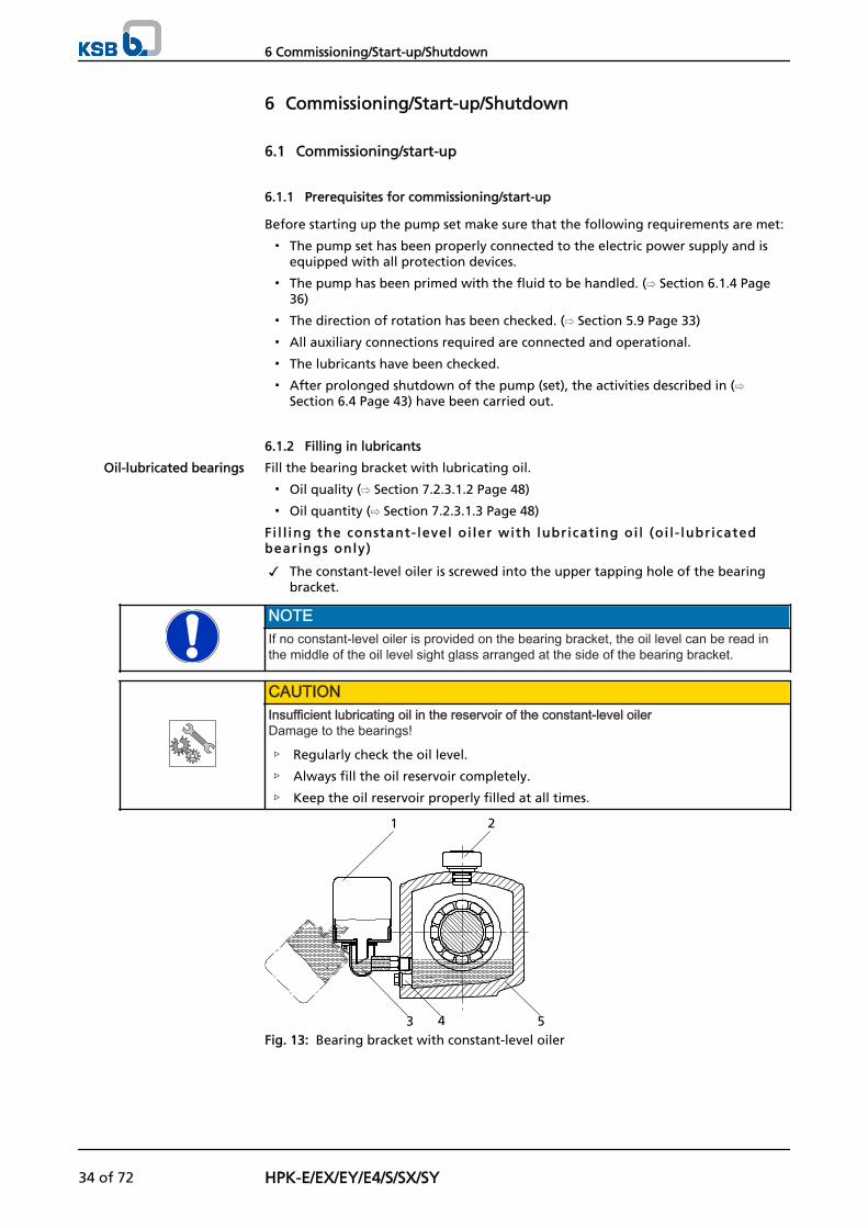
3 4 5Fig. 13: Bearing bracket with constant-level oiler
Oil-lubricated bearings
6 Commissioning/Start-up/Shutdown
34 of 72 HPK-E/EX/EY/E4/S/SX/SY
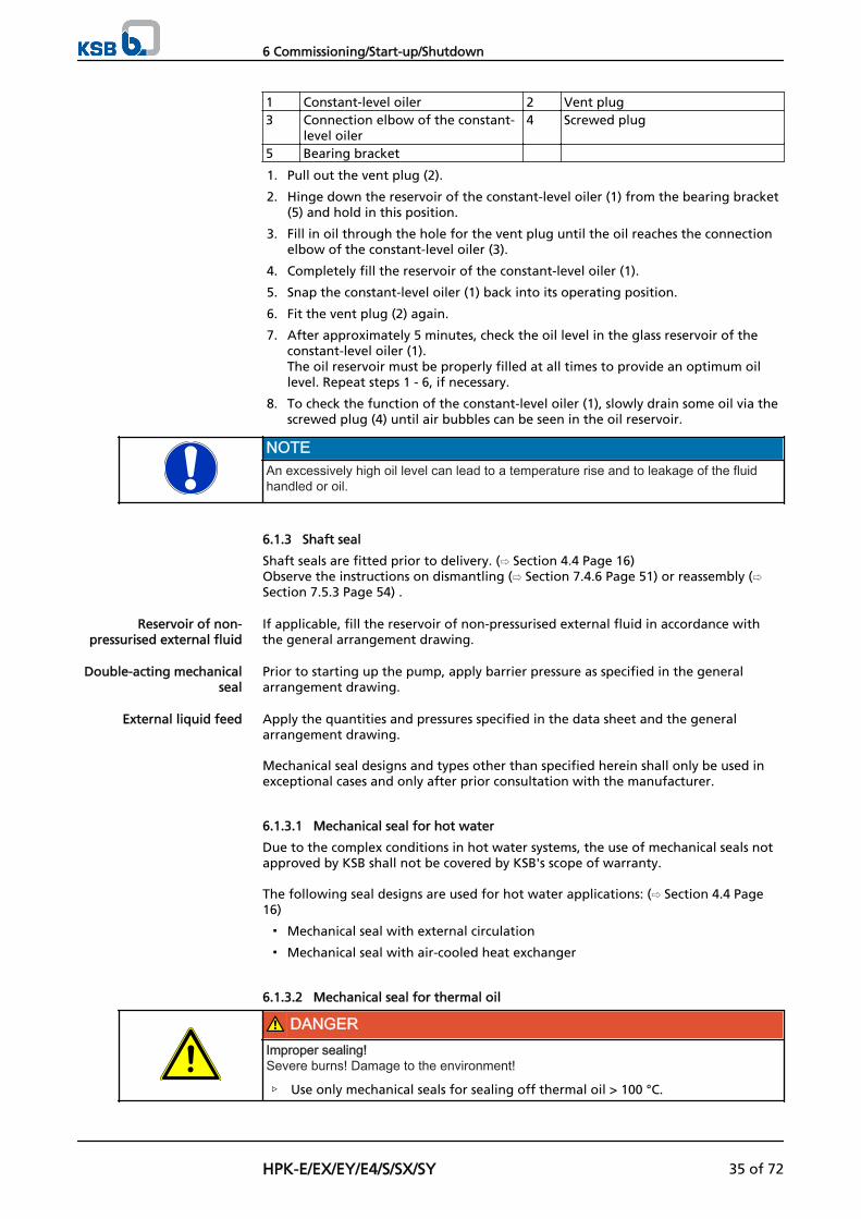
1 Constant-level oiler 2 Vent plug3 Connection elbow of the constant-
level oiler4 Screwed plug
5 Bearing bracket
1. Pull out the vent plug (2).
2. Hinge down the reservoir of the constant-level oiler (1) from the bearing bracket(5) and hold in this position.
3. Fill in oil through the hole for the vent plug until the oil reaches the connectionelbow of the constant-level oiler (3).
4. Completely fill the reservoir of the constant-level oiler (1).
5. Snap the constant-level oiler (1) back into its operating position.
6. Fit the vent plug (2) again.
7. After approximately 5 minutes, check the oil level in the glass reservoir of theconstant-level oiler (1). The oil reservoir must be properly filled at all times to provide an optimum oillevel. Repeat steps 1 - 6, if necessary.
8. To check the function of the constant-level oiler (1), slowly drain some oil via thescrewed plug (4) until air bubbles can be seen in the oil reservoir.
NOTEAn excessively high oil level can lead to a temperature rise and to leakage of the fluidhandled or oil.
6.1.3 Shaft seal
Shaft seals are fitted prior to delivery. (⇨ Section 4.4 Page 16) Observe the instructions on dismantling (⇨ Section 7.4.6 Page 51) or reassembly (⇨Section 7.5.3 Page 54) .
If applicable, fill the reservoir of non-pressurised external fluid in accordance withthe general arrangement drawing.
Prior to starting up the pump, apply barrier pressure as specified in the generalarrangement drawing.
Apply the quantities and pressures specified in the data sheet and the generalarrangement drawing.
Mechanical seal designs and types other than specified herein shall only be used inexceptional cases and only after prior consultation with the manufacturer.
6.1.3.1 Mechanical seal for hot water
Due to the complex conditions in hot water systems, the use of mechanical seals notapproved by KSB shall not be covered by KSB's scope of warranty.
The following seal designs are used for hot water applications: (⇨ Section 4.4 Page16)
▪ Mechanical seal with external circulation
▪ Mechanical seal with air-cooled heat exchanger
6.1.3.2 Mechanical seal for thermal oil
DANGERImproper sealing!Severe burns! Damage to the environment!
▷ Use only mechanical seals for sealing off thermal oil > 100 °C.
Reservoir of non-pressurised external fluid
Double-acting mechanicalseal
External liquid feed
6 Commissioning/Start-up/Shutdown
HPK-E/EX/EY/E4/S/SX/SY 35 of 72
DANGERQuench supplySerious injury!
▷ Only operate quench supply systems outdoors, far away from persons andpotential sources of ignition.
CAUTIONContamination, deposits of cracked products and carbon residues on the seal facesDamage to the mechanical seal!
▷ Mechanical seal must only be operated with quench supply.
To prevent deposits of cracked products and carbon residues (from carbonised oil) onthe seal faces, use only mechanical seal systems designed to prevent contact betweenoxygen and the mechanical seal faces.
The following seal designs are used for thermal oil applications: (⇨ Section 4.4 Page16)
▪ Single-acting mechanical seal with steam/nitrogen quench
If steam quench is used, the steam quench feed rate must be adjusted so thatonly a small plume of steam escapes between the shaft protecting sleeve and thethrottling bush.
– Quench medium: steam (max. 160 °C) or nitrogen
– Required feed rate: approx. 1 kg/hour
– Required pressure: 0.1 bar max. (observe any additional information given inthe general arrangement drawing!)
▪ Mechanical seal in tandem arrangement with quench liquid
In mechanical seal systems in tandem arrangement the outboard mechanical sealserves as safety back-up seal designed to provide temporary sealing if theinboard seal fails.The mechanical seal system must be supplied with a quench liquid (typically coldthermal oil) in order to dissipate the friction heat generated at the seal faces ofthe outboard mechanical seal and to prevent the seal faces of the inboardmechanical seal from coming into contact with atmospheric oxygen. This isusually assured by means of a quench pot.Quench pot installation and operating mode see supplementary sheet.
6.1.4 Priming and venting the pump
DANGERRisk of potentially explosive atmosphere inside the pumpExplosion hazard!
▷ The pump internals in contact with the fluid to be handled, including the sealchamber and auxiliary systems must be filled with the fluid to be handled at alltimes.
▷ Provide sufficient inlet pressure.
▷ Provide an appropriate monitoring system.
DANGERShaft seal failure caused by dry runningHot or toxic fluid could escape!Damage to the pump!
▷ Before starting up the pump set, vent the pump and suction line and prime withthe fluid to be handled.
1. Vent the pump and suction line and prime with the fluid to be handled.
2. Fully open the shut-off element in the suction line.
6 Commissioning/Start-up/Shutdown
36 of 72 HPK-E/EX/EY/E4/S/SX/SY
3. Fully open all auxiliary connections (barrier fluid, flushing liquid, etc).
6.1.5 Water cooling
CAUTIONDeposit-forming, aggressive cooling waterDamage to the pump!
▷ Observe the cooling water quality.
Observe the following quality data of the cooling water:
▪ Not liable to form deposits
▪ Not aggressive
▪ Free from suspended solids
▪ Average hardness 5 °dH (~1mmol/l)
▪ pH > 8
▪ Conditioned and neutral with regard to mechanical corrosion
▪ Inlet temperature tE = 10 to 30 °C5)
Outlet temperature tA= 45 °C (max.)5)
The cooling liquid quantities indicated are based on Δt = 15 °C (max.).In the case of deviations, the cooling liquid requirement changes in direct proportionto the change in the temperature difference.
QCooling waterfor Δtx = QCooling water x (15 : Δtx)
6.1.6 Cooling of the shaft seal
CAUTIONVaporisation pressure of fluid handled higher than atmospheric pressureDamage to the shaft seal/pump!
▷ Cool the shaft seal.
▷ Provide sufficient quantities of cooling liquid (see table).
The casing cover's cooling chamber permits intensive cooling of the shaft sealwithout cooling down the fluid handled.
NOTEThe vaporisation pressure varies depending on the fluid handled, the system pressureand the material of the shaft seal (e.g. hot water).
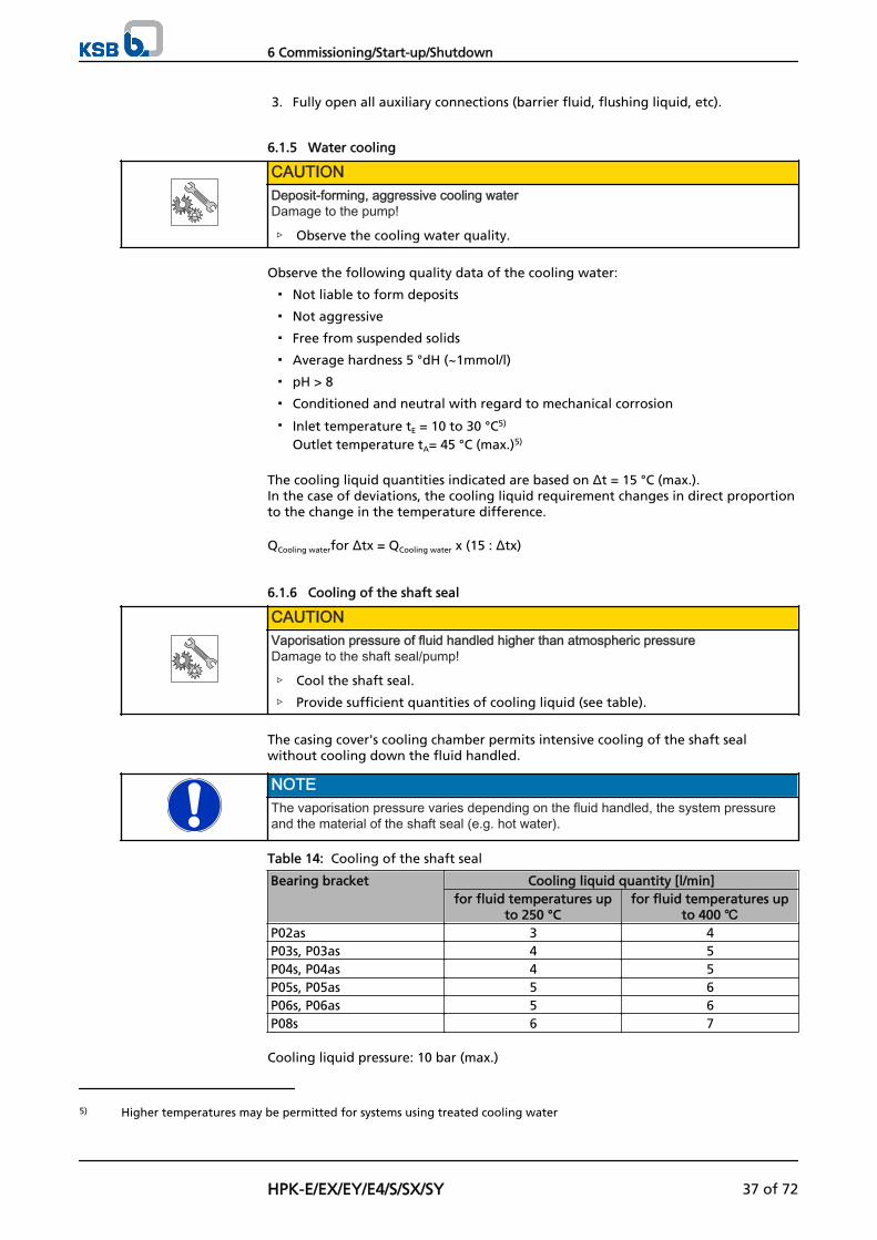
Table 14: Cooling of the shaft seal
Bearing bracket Cooling liquid quantity [l/min]for fluid temperatures up
to 250 °Cfor fluid temperatures up
to 400 ℃P02as 3 4P03s, P03as 4 5P04s, P04as 4 5P05s, P05as 5 6P06s, P06as 5 6P08s 6 7
Cooling liquid pressure: 10 bar (max.)
5) Higher temperatures may be permitted for systems using treated cooling water
6 Commissioning/Start-up/Shutdown
HPK-E/EX/EY/E4/S/SX/SY 37 of 72
6.1.7 Bearing bracket cooling
The bearing load or the temperature of the fluid handled have little impact on thebearing temperature. Rather, bearing temperature is determined by the rotationalspeed, ambient temperature, oil quality and oil level.
If no bearing temperature limits are specified, no cooling system is required for 4-pole drives.On pumps with 2-pole drive, P04, P05, and P06 bearing assemblies must be cooled ifthe fluid temperature is 200 °C or higher.
When using the cooled bearing bracket the following values shall be met:
▪ Cooling liquid quantity: approx. 3.3 l/min
▪ Cooling liquid pressure: 10 bar (max.)
6.1.8 Cooling of the heat exchanger
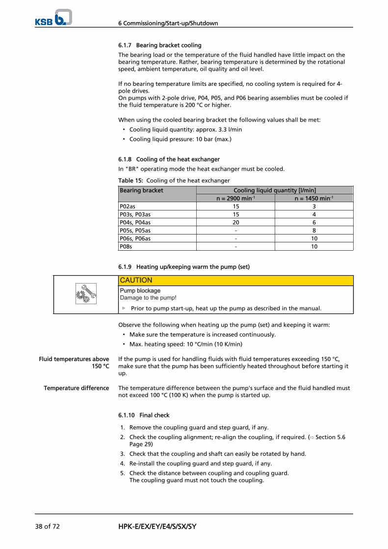
In "BR" operating mode the heat exchanger must be cooled.
Table 15: Cooling of the heat exchanger
Bearing bracket Cooling liquid quantity [l/min]n = 2900 min-1 n = 1450 min-1
P02as 15 3P03s, P03as 15 4P04s, P04as 20 6P05s, P05as - 8P06s, P06as - 10P08s - 10
6.1.9 Heating up/keeping warm the pump (set)
CAUTIONPump blockageDamage to the pump!
▷ Prior to pump start-up, heat up the pump as described in the manual.
Observe the following when heating up the pump (set) and keeping it warm:
▪ Make sure the temperature is increased continuously.
▪ Max. heating speed: 10 °C/min (10 K/min)
If the pump is used for handling fluids with fluid temperatures exceeding 150 °C,make sure that the pump has been sufficiently heated throughout before starting itup.
The temperature difference between the pump's surface and the fluid handled mustnot exceed 100 °C (100 K) when the pump is started up.
6.1.10 Final check
1. Remove the coupling guard and step guard, if any.
2. Check the coupling alignment; re-align the coupling, if required. (⇨ Section 5.6Page 29)
3. Check that the coupling and shaft can easily be rotated by hand.
4. Re-install the coupling guard and step guard, if any.
5. Check the distance between coupling and coupling guard.The coupling guard must not touch the coupling.
Fluid temperatures above150 °C
Temperature difference
6 Commissioning/Start-up/Shutdown
38 of 72 HPK-E/EX/EY/E4/S/SX/SY
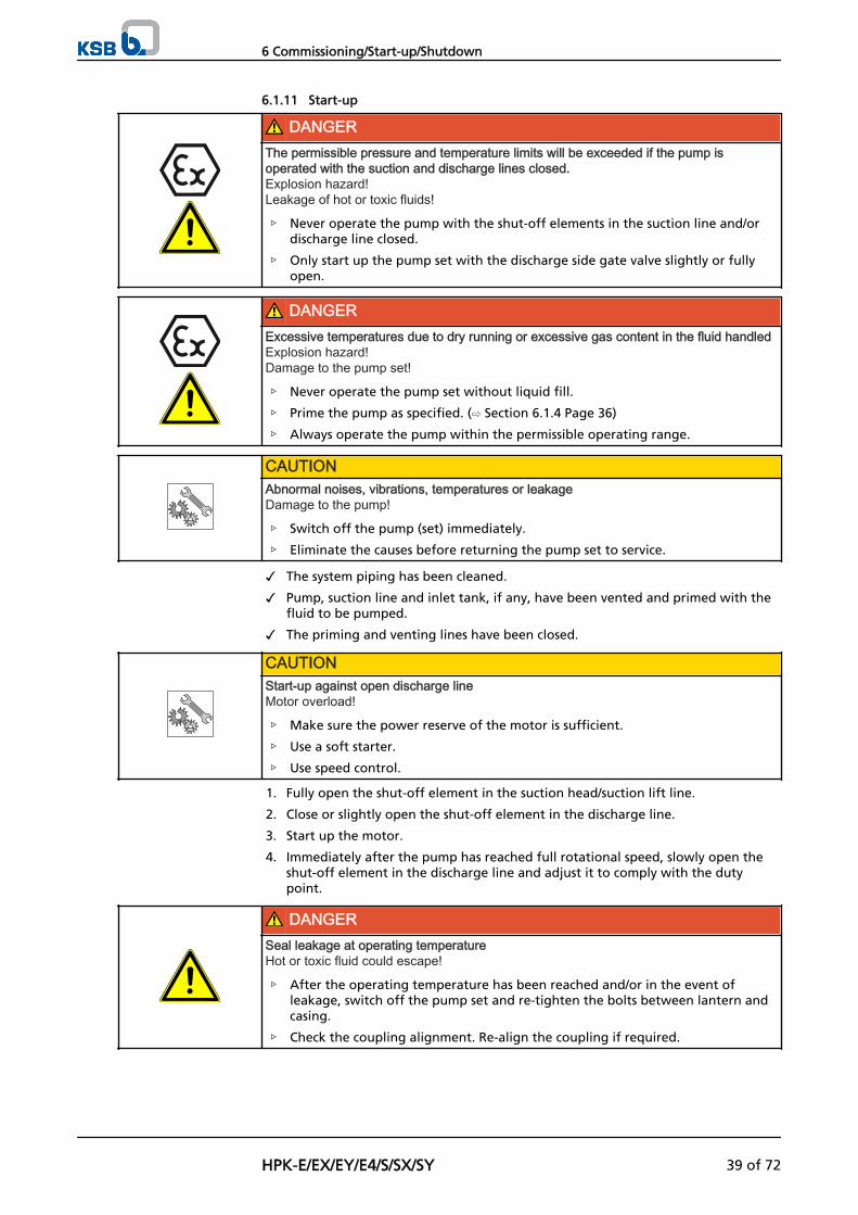
6.1.11 Start-up
DANGERThe permissible pressure and temperature limits will be exceeded if the pump isoperated with the suction and discharge lines closed.Explosion hazard!Leakage of hot or toxic fluids!
▷ Never operate the pump with the shut-off elements in the suction line and/ordischarge line closed.
▷ Only start up the pump set with the discharge side gate valve slightly or fullyopen.
DANGERExcessive temperatures due to dry running or excessive gas content in the fluid handledExplosion hazard!Damage to the pump set!
▷ Never operate the pump set without liquid fill.
▷ Prime the pump as specified. (⇨ Section 6.1.4 Page 36)
▷ Always operate the pump within the permissible operating range.
CAUTIONAbnormal noises, vibrations, temperatures or leakageDamage to the pump!
▷ Switch off the pump (set) immediately.
▷ Eliminate the causes before returning the pump set to service.
✓ The system piping has been cleaned.
✓ Pump, suction line and inlet tank, if any, have been vented and primed with thefluid to be pumped.
✓ The priming and venting lines have been closed.
CAUTIONStart-up against open discharge lineMotor overload!
▷ Make sure the power reserve of the motor is sufficient.
▷ Use a soft starter.
▷ Use speed control.
1. Fully open the shut-off element in the suction head/suction lift line.
2. Close or slightly open the shut-off element in the discharge line.
3. Start up the motor.
4. Immediately after the pump has reached full rotational speed, slowly open theshut-off element in the discharge line and adjust it to comply with the dutypoint.
DANGERSeal leakage at operating temperatureHot or toxic fluid could escape!
▷ After the operating temperature has been reached and/or in the event ofleakage, switch off the pump set and re-tighten the bolts between lantern andcasing.
▷ Check the coupling alignment. Re-align the coupling if required.
6 Commissioning/Start-up/Shutdown
HPK-E/EX/EY/E4/S/SX/SY 39 of 72
5. When the operating temperature has been reached and/or in the event ofleakage, switch off the pump set and re-tighten the bolts between lantern andcasing.
6. Check the coupling alignment and re-align the coupling, if required.
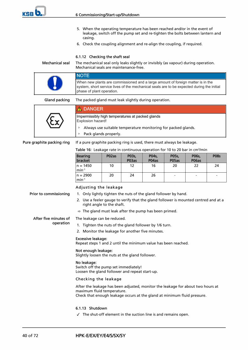
6.1.12 Checking the shaft seal
The mechanical seal only leaks slightly or invisibly (as vapour) during operation.Mechanical seals are maintenance-free.
NOTEWhen new plants are commissioned and a large amount of foreign matter is in thesystem, short service lives of the mechanical seals are to be expected during the initialphase of plant operation.
The packed gland must leak slightly during operation.
DANGERImpermissibly high temperatures at packed glandsExplosion hazard!
▷ Always use suitable temperature monitoring for packed glands.
▷ Pack glands properly.
If a pure graphite packing ring is used, there must always be leakage.
Table 16: Leakage rate in continuous operation for 10 to 20 bar in cm3/min
Bearingbracket
P02as P03s,P03as
P04s,P04as
P05s,P05as
P06s,P06as
P08s
n = 1450min-1
10 12 16 20 22 24
n = 2900min-1
20 24 26 - - -
Adjust ing the leakage
1. Only lightly tighten the nuts of the gland follower by hand.
2. Use a feeler gauge to verify that the gland follower is mounted centred and at aright angle to the shaft.
⇨ The gland must leak after the pump has been primed.
The leakage can be reduced.
1. Tighten the nuts of the gland follower by 1/6 turn.
2. Monitor the leakage for another five minutes.
Excessive leakage:Repeat steps 1 and 2 until the minimum value has been reached.
Not enough leakage:Slightly loosen the nuts at the gland follower.
No leakage:Switch off the pump set immediately!Loosen the gland follower and repeat start-up.
Checking the leakage
After the leakage has been adjusted, monitor the leakage for about two hours atmaximum fluid temperature. Check that enough leakage occurs at the gland at minimum fluid pressure.
6.1.13 Shutdown
✓ The shut-off element in the suction line is and remains open.
Mechanical seal
Gland packing
Pure graphite packing ring
Prior to commissioning
After five minutes ofoperation
6 Commissioning/Start-up/Shutdown
40 of 72 HPK-E/EX/EY/E4/S/SX/SY
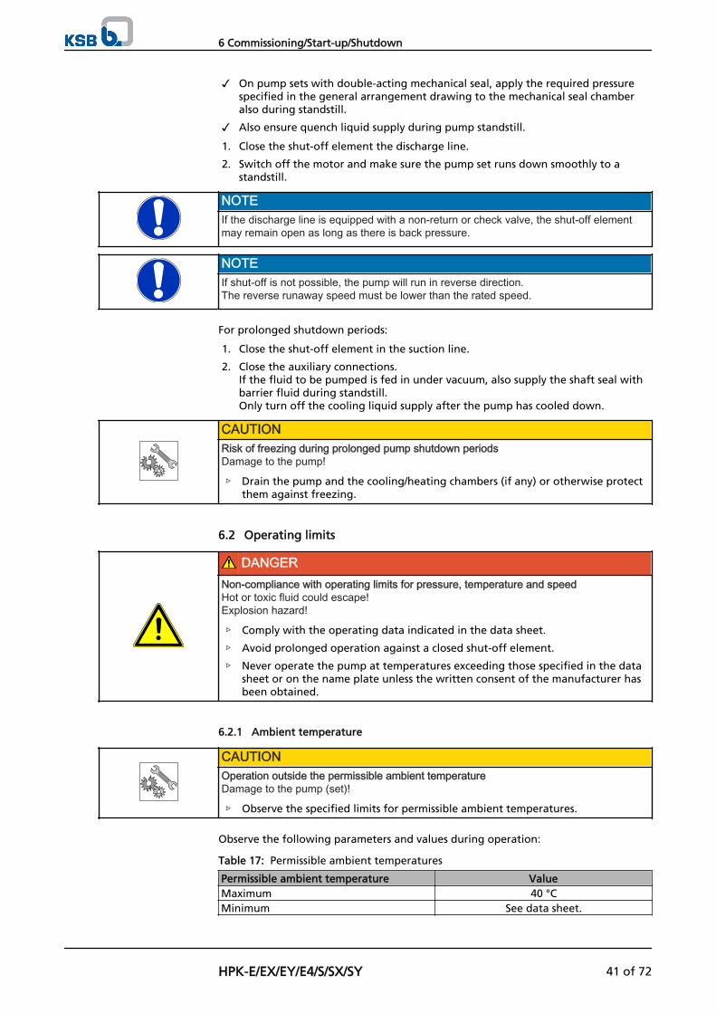
✓ On pump sets with double-acting mechanical seal, apply the required pressurespecified in the general arrangement drawing to the mechanical seal chamberalso during standstill.
✓ Also ensure quench liquid supply during pump standstill.
1. Close the shut-off element the discharge line.
2. Switch off the motor and make sure the pump set runs down smoothly to astandstill.
NOTEIf the discharge line is equipped with a non-return or check valve, the shut-off elementmay remain open as long as there is back pressure.
NOTEIf shut-off is not possible, the pump will run in reverse direction.The reverse runaway speed must be lower than the rated speed.
For prolonged shutdown periods:
1. Close the shut-off element in the suction line.
2. Close the auxiliary connections. If the fluid to be pumped is fed in under vacuum, also supply the shaft seal withbarrier fluid during standstill.Only turn off the cooling liquid supply after the pump has cooled down.
CAUTIONRisk of freezing during prolonged pump shutdown periodsDamage to the pump!
▷ Drain the pump and the cooling/heating chambers (if any) or otherwise protectthem against freezing.
6.2 Operating limits
DANGERNon-compliance with operating limits for pressure, temperature and speedHot or toxic fluid could escape!Explosion hazard!
▷ Comply with the operating data indicated in the data sheet.
▷ Avoid prolonged operation against a closed shut-off element.
▷ Never operate the pump at temperatures exceeding those specified in the datasheet or on the name plate unless the written consent of the manufacturer hasbeen obtained.
6.2.1 Ambient temperature
CAUTIONOperation outside the permissible ambient temperatureDamage to the pump (set)!
▷ Observe the specified limits for permissible ambient temperatures.
Observe the following parameters and values during operation:
Table 17: Permissible ambient temperatures
Permissible ambient temperature ValueMaximum 40 °CMinimum See data sheet.
6 Commissioning/Start-up/Shutdown
HPK-E/EX/EY/E4/S/SX/SY 41 of 72
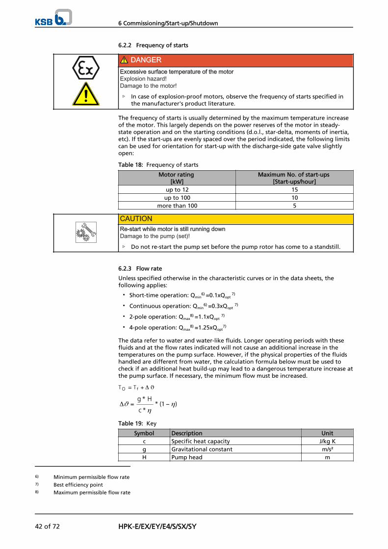
6.2.2 Frequency of starts
DANGERExcessive surface temperature of the motorExplosion hazard!Damage to the motor!
▷ In case of explosion-proof motors, observe the frequency of starts specified inthe manufacturer's product literature.
The frequency of starts is usually determined by the maximum temperature increaseof the motor. This largely depends on the power reserves of the motor in steady-state operation and on the starting conditions (d.o.l., star-delta, moments of inertia,etc). If the start-ups are evenly spaced over the period indicated, the following limitscan be used for orientation for start-up with the discharge-side gate valve slightlyopen:
Table 18: Frequency of starts
Motor rating [kW]
Maximum No. of start-ups [Start-ups/hour]
up to 12 15up to 100 10
more than 100 5
CAUTIONRe-start while motor is still running downDamage to the pump (set)!
▷ Do not re-start the pump set before the pump rotor has come to a standstill.
6.2.3 Flow rate
Unless specified otherwise in the characteristic curves or in the data sheets, thefollowing applies:
▪ Short-time operation: Qmin6) =0.1xQopt
7)
▪ Continuous operation: Qmin6) =0.3xQopt 7)
▪ 2-pole operation: Qmax8) =1.1xQopt 7)
▪ 4-pole operation: Qmax8) =1.25xQopt
7)
The data refer to water and water-like fluids. Longer operating periods with thesefluids and at the flow rates indicated will not cause an additional increase in thetemperatures on the pump surface. However, if the physical properties of the fluidshandled are different from water, the calculation formula below must be used tocheck if an additional heat build-up may lead to a dangerous temperature increase atthe pump surface. If necessary, the minimum flow must be increased.
Table 19: Key
Symbol Description Unitc Specific heat capacity J/kg Kg Gravitational constant m/s²H Pump head m
6) Minimum permissible flow rate7) Best efficiency point8) Maximum permissible flow rate
6 Commissioning/Start-up/Shutdown
42 of 72 HPK-E/EX/EY/E4/S/SX/SY
Symbol Description UnitTf Temperature of the fluid handled °C
To Temperature at the casing surface °C
Pump efficiency at duty point -Temperature difference °C
6.2.4 Density of the fluid handled
The power input of the pump increases in proportion to the density of the fluidhandled.
CAUTIONImpermissibly high density of the fluid handledMotor overload!
▷ Observe the information on fluid density indicated in the data sheet.
▷ Make sure the power reserve of the motor is sufficient.
6.2.5 Abrasive fluids
Do not exceed the maximum permissible solids content specified in the data sheet.When the pump handles fluids containing abrasive substances, increased wear of thehydraulic system and the shaft seal are to be expected. In this case, reduce theintervals commonly recommended for servicing and maintenance.
6.3 Shutdown/storage/preservation
6.3.1 Measures to be taken for shutdown
The pump (set) remains instal led
✓ Sufficient fluid is supplied for the operation check run of the pump.
1. Start up the pump (set) regularly once a month or once every three months forapproximately five minutes during prolonged shutdown periods. This will prevent the formation of deposits within the pump and the pumpintake area.
The pump (set) i s removed from the pipe and stored
✓ The pump has been properly drained (⇨ Section 7.3 Page 49) and the safetyinstructions for dismantling the pump have been observed. (⇨ Section 7.4.1 Page50)
1. Spray-coat the inside wall of the pump casing, and in particular the impellerclearance areas, with a preservative.
2. Spray the preservative through the suction and discharge nozzles.It is advisable to then close the pump nozzles (e.g. with plastic caps or similar).
3. Oil or grease all blank parts and surfaces of the pump (with silicone-free oil andgrease, food-approved if required) to protect them against corrosion. Observe the additional instructions. (⇨ Section 3.2 Page 14)
If the pump set is to be stored temporarily, only preserve the wetted componentsmade of low alloy materials. Commercially available preservatives can be used for thispurpose. Observe the manufacturer's instructions for application/removal.
Observe any additional instructions and information provided. (⇨ Section 3 Page 14)
6.4 Returning to service after storage
For returning the pump to service observe the sections on commissioning/start-up (⇨Section 6.1 Page 34) and the operating limits (⇨ Section 6.2 Page 41) .
In addition, carry out all servicing/maintenance operations before returning thepump (set) to service. (⇨ Section 7 Page 45)
6 Commissioning/Start-up/Shutdown
HPK-E/EX/EY/E4/S/SX/SY 43 of 72
WARNINGFailure to re-install or re-activate protective devicesRisk of personal injury from moving parts or escaping fluid!
▷ As soon as the work is completed, re-install and/or re-activate any safety-relevant and protective devices.
NOTEIf the pump has been out of service for more than one year, replace all elastomer seals.
6 Commissioning/Start-up/Shutdown
44 of 72 HPK-E/EX/EY/E4/S/SX/SY
7 Servicing/Maintenance
7.1 Safety regulations
DANGERImproperly serviced pump setExplosion hazard!Damage to the pump set!
▷ Service the pump set regularly.
▷ Prepare a maintenance schedule with special emphasis on lubricants, shaft sealand coupling.
The operator ensures that all maintenance, inspection and installation work isperformed by authorised, qualified specialist personnel who are thoroughly familiarwith the manual.
WARNINGPump set started up inadvertentlyRisk of injury by moving parts!
▷ Always make sure the electrical connections are disconnected before carryingout work on the pump set.
▷ Make sure that the pump set cannot be started up accidentally.
WARNINGFluids posing a health hazard or hot fluidsRisk of personal injury!
▷ Observe all relevant laws.
▷ When draining the fluid take appropriate measures to protect persons and theenvironment.
▷ Decontaminate pumps handling fluids posing a health hazard.
A regular maintenance schedule will help avoid expensive repairs and contribute totrouble-free, reliable operation of the pump (set) with a minimum of maintenanceexpenditure and work.
NOTEAll maintenance, service and installation work can be carried out by KSB Service. Findyour contact in the attached "Addresses" booklet or on the Internet at www.ksb.com/contact".
Never use force when dismantling and reassembling a pump set.
7.2 Servicing/inspection
7.2.1 Supervision of operation
DANGERExcessive temperatures as a result of bearings running hot or defective bearing sealsExplosion hazard!Fire hazard!Damage to the pump set!
▷ Regularly check the lubricant level.
▷ Regularly check the rolling element bearings for running noises.
7 Servicing/Maintenance
HPK-E/EX/EY/E4/S/SX/SY 45 of 72
CAUTIONIncreased wear due to dry runningDamage to the pump set!
▷ Never operate the pump set without liquid fill.
▷ Never close the shut-off element in the suction line and/or supply line duringpump operation.
CAUTIONImpermissibly high temperature of fluid handledDamage to the pump!
▷ Prolonged operation against a closed shut-off element is not permitted (heatingup of the fluid).
▷ Observe the temperature limits in the data sheet and in the section onOperating limits. (⇨ Section 6.2 Page 41)
While the pump is in operation, observe and check the following:
▪ The pump must run quietly and free from vibrations at all times.
▪ In case of oil lubrication, ensure the oil level is correct. (⇨ Section 6.1.2 Page 34)
▪ Check the shaft seal.
▪ Check the static seals for leakages.
▪ Check the rolling element bearings for running noises.Vibrations, noise and an increase in current input occurring during unchangedoperating conditions indicate wear.
▪ Monitor the correct functioning of any auxiliary connections.
▪ Cooling systemTake the pump out of service at least once a year to thoroughly clean the coolingsystem.
▪ Monitor the stand-by pump.To make sure that the stand-by pumps are ready for operation, start them uponce a week.
▪ Monitor the bearing temperature.The bearing temperature must not exceed 90 °C (measured on the outside of thebearing bracket).
CAUTIONOperation outside the permissible bearing temperatureDamage to the pump!
▷ The bearing temperature of the pump (set) must never exceed 90 °C (measuredon the outside of the bearing bracket).
NOTEAfter commissioning, increased temperatures may occur at grease-lubricated rollingelement bearings due to the running-in process. The final bearing temperature is onlyreached after a certain period of operation (up to 48 h depending on the conditions).
7 Servicing/Maintenance
46 of 72 HPK-E/EX/EY/E4/S/SX/SY
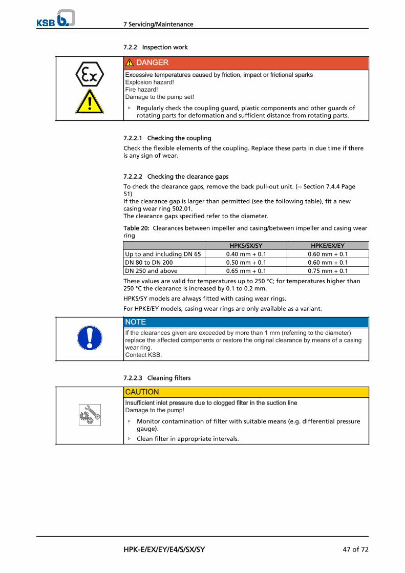
7.2.2 Inspection work
DANGERExcessive temperatures caused by friction, impact or frictional sparksExplosion hazard!Fire hazard!Damage to the pump set!
▷ Regularly check the coupling guard, plastic components and other guards ofrotating parts for deformation and sufficient distance from rotating parts.
7.2.2.1 Checking the coupling
Check the flexible elements of the coupling. Replace these parts in due time if thereis any sign of wear.
7.2.2.2 Checking the clearance gaps
To check the clearance gaps, remove the back pull-out unit. (⇨ Section 7.4.4 Page51)If the clearance gap is larger than permitted (see the following table), fit a newcasing wear ring 502.01.The clearance gaps specified refer to the diameter.
Table 20: Clearances between impeller and casing/between impeller and casing wearring
HPKS/SX/SY HPKE/EX/EYUp to and including DN 65 0.40 mm + 0.1 0.60 mm + 0.1DN 80 to DN 200 0.50 mm + 0.1 0.60 mm + 0.1DN 250 and above 0.65 mm + 0.1 0.75 mm + 0.1
These values are valid for temperatures up to 250 °C; for temperatures higher than250 °C the clearance is increased by 0.1 to 0.2 mm.
HPKS/SY models are always fitted with casing wear rings.
For HPKE/EY models, casing wear rings are only available as a variant.
NOTEIf the clearances given are exceeded by more than 1 mm (referring to the diameter)replace the affected components or restore the original clearance by means of a casingwear ring. Contact KSB.
7.2.2.3 Cleaning filters
CAUTIONInsufficient inlet pressure due to clogged filter in the suction lineDamage to the pump!
▷ Monitor contamination of filter with suitable means (e.g. differential pressuregauge).
▷ Clean filter in appropriate intervals.
7 Servicing/Maintenance
HPK-E/EX/EY/E4/S/SX/SY 47 of 72
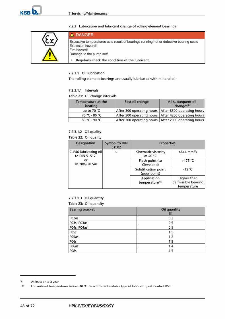
7.2.3 Lubrication and lubricant change of rolling element bearings
DANGERExcessive temperatures as a result of bearings running hot or defective bearing sealsExplosion hazard!Fire hazard!Damage to the pump set!
▷ Regularly check the condition of the lubricant.
7.2.3.1 Oil lubrication
The rolling element bearings are usually lubricated with mineral oil.
7.2.3.1.1 Intervals
Table 21: Oil change intervals
Temperature at thebearing
First oil change All subsequent oilchanges9)
up to 70 ℃ After 300 operating hours After 8500 operating hours70 °C - 80 °C After 300 operating hours After 4200 operating hours80 °C - 90 °C After 300 operating hours After 2000 operating hours
7.2.3.1.2 Oil quality
Table 22: Oil quality
Designation Symbol to DIN51502
Properties
CLP46 lubricating oilto DIN 51517
orHD 20W/20 SAE
□ Kinematic viscosityat 40 °C
46±4 mm²/s
Flash point (toCleveland)
+175 ℃
Solidification point(pour point)
-15 ℃
Applicationtemperature10)
Higher thanpermissible bearing
temperature
7.2.3.1.3 Oil quantity
Table 23: Oil quantity
Bearing bracket Oil quantity[l]
P02as 0.3P03s, P03as 0.5P04s, P04as 0.5P05s 1.5P05as 1.2P06s 1.8P06as 1.4P08s 4.5
9) At least once a year10) For ambient temperatures below -10 °C use a different suitable type of lubricating oil. Contact KSB.
7 Servicing/Maintenance
48 of 72 HPK-E/EX/EY/E4/S/SX/SY
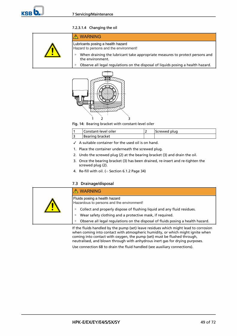
7.2.3.1.4 Changing the oil
WARNINGLubricants posing a health hazardHazard to persons and the environment!
▷ When draining the lubricant take appropriate measures to protect persons andthe environment.
▷ Observe all legal regulations on the disposal of liquids posing a health hazard.
1 2 3Fig. 14: Bearing bracket with constant-level oiler
1 Constant-level oiler 2 Screwed plug3 Bearing bracket
✓ A suitable container for the used oil is on hand.
1. Place the container underneath the screwed plug.
2. Undo the screwed plug (2) at the bearing bracket (3) and drain the oil.
3. Once the bearing bracket (3) has been drained, re-insert and re-tighten thescrewed plug (2).
4. Re-fill with oil. (⇨ Section 6.1.2 Page 34)
7.3 Drainage/disposal
WARNINGFluids posing a health hazardHazardous to persons and the environment!
▷ Collect and properly dispose of flushing liquid and any fluid residues.
▷ Wear safety clothing and a protective mask, if required.
▷ Observe all legal regulations on the disposal of fluids posing a health hazard.
If the fluids handled by the pump (set) leave residues which might lead to corrosionwhen coming into contact with atmospheric humidity, or which might ignite whencoming into contact with oxygen, the pump (set) must be flushed through,neutralised, and blown through with anhydrous inert gas for drying purposes.
Use connection 6B to drain the fluid handled (see auxiliary connections).
7 Servicing/Maintenance
HPK-E/EX/EY/E4/S/SX/SY 49 of 72
7.4 Dismantling the pump set
7.4.1 General notes/Safety regulations
WARNINGUnqualified personnel performing work on the pump (set)Risk of personal injury!
▷ Always have repair and maintenance work performed by specially trained,qualified personnel.
WARNINGHot surfaceRisk of personal injury!
▷ Allow the pump set to cool down to ambient temperature.
Observe the general safety instructions and information. (⇨ Section 7 Page 45)
For any work on the motor, observe the instructions of the relevant motormanufacturer.
For dismantling and reassembly refer to the general assembly drawing.
In case of damage you can always contact our service staff.
DANGERInsufficient preparation of work on the pump (set)Risk of personal injury!
▷ Properly shut down the pump set. (⇨ Section 6.1.13 Page 40)
▷ Close the shut-off elements in the suction and discharge line.
▷ Drain the pump and release the pump pressure. (⇨ Section 7.3 Page 49)
▷ Close any auxiliary connections.
▷ Allow the pump set to cool down to ambient temperature.
7.4.2 Preparing the pump set
1. Disconnect the power supply (e.g. at the motor).
2. Disconnect and remove all auxiliary pipework.
3. Remove the air-cooled heat exchanger, if any.
4. Remove the coupling guard.
5. Remove the coupling spacer, if any.
6. Drain the oil. (⇨ Section 7.2.3.1.4 Page 49)
7.4.3 Dismantling the motor
NOTEFor pump sets with spacer-type couplings, the back pull-out unit can be removed whilethe motor remains bolted to the baseplate.
1. Disconnect the motor from the power supply.
2. Unbolt the motor from the baseplate.
3. Shift the motor to separate it from the pump.
7 Servicing/Maintenance
50 of 72 HPK-E/EX/EY/E4/S/SX/SY
WARNINGMotor tipping overRisk of squashing hands and feet!
▷ Suspend or support the motor to prevent it from tipping over.
7.4.4 Removing the back pull-out unit
✓ Pumps without spacer-type coupling: the motor has been removed.
WARNINGBack pull-out unit tipping overRisk of squashing hands and feet!
▷ Suspend or support the bearing bracket at the pump end.
1. If required, suspend or support bearing bracket 330 to prevent it from tippingover.
2. Unbolt support foot 183 from the baseplate.
3. Undo hexagon nut 920.01 at the volute casing.
4. Pull the back pull-out unit out of the volute casing.
5. Remove and dispose of joint ring 411.10.
6. Place the back pull-out unit on a clean and level surface.
7.4.5 Removing the impeller
✓ The notes and steps stated in (⇨ Section 7.4.1 Page 50) to (⇨ Section 7.4.4 Page51) have been observed/carried out.
✓ The back pull-out unit is kept in a clean and level assembly area.
1. Undo impeller nut 922 (right-hand thread).
2. Remove impeller 230 with an impeller removal device.
3. Place impeller 230 on a clean and level surface.
4. Remove keys 940.1 from shaft 210.
5. Remove and dispose of joint rings 411.31/411.32.
7.4.6 Dismantling the shaft seal
7.4.6.1 Removing the mechanical seal
✓ The notes and steps stated in (⇨ Section 7.4.1 Page 50) to (⇨ Section 7.4.5 Page51) have been observed/carried out.
✓ The back pull-out unit is kept in a clean and level assembly area.
1. Undo hexagon nuts 920.02 and push back seal cover 471.01 (if fitted) until it restsagainst thrower 507.01.
2. Remove casing cover 161 with O-ring 412.01.
3. Remove and dispose of O-ring 412.01.
4. Pull complete mechanical seal 433 with shaft protecting sleeve 524.01, seal cover471 and thrower 507.01 off shaft 210.
7.4.6.2 Dismantling the packed gland
✓ The notes and steps stated in (⇨ Section 7.4.1 Page 50) to (⇨ Section 7.4.5 Page51) have been observed/carried out.
✓ The back pull-out unit is kept in a clean and level assembly area.
7 Servicing/Maintenance
HPK-E/EX/EY/E4/S/SX/SY 51 of 72
1. Unscrew hexagon nuts 920.02 at gland follower 452 and remove the glandfollower.
2. Remove stuffing box ring 454.01 and drip plate 463.01.
3. Remove casing cover 161 with O-ring 412.01 and gland packing 461.01.
4. Remove packing rings 461.01 and lantern ring 458.01, if any, from the packingchamber.
5. Pull off guard 680.
6. Pull shaft protecting sleeve 524.01 and thrower 507.01 off shaft 210.
7.4.7 Dismantling the bearings
✓ The notes and steps stated in (⇨ Section 7.4.1 Page 50) to (⇨ Section 7.4.6 Page51) have been observed/carried out.
✓ The bearing bracket is kept in a clean and level assembly area.
1. Unscrew hexagon nuts 920.04 at the flange of bearing bracket lantern 344.
2. Remove bearing bracket lantern 344.
3. Unscrew the socket head cap screw in the coupling hub.
4. Pull the coupling half off the pump shaft with a puller.
5. Remove key 940.02 and thrower 507.02.
6. Undo screws 914.02 and remove motor-end bearing cover 360.02 and joint ring400.02.
7. Undo screws 914.01 and remove pump-end bearing cover 360.01 and joint ring400.01.
8. Carefully drive shaft 210 together with angular contact ball bearing 320.02 andthe inner ring of cylindrical roller bearing 322.01 out of the bearing brackettowards the drive end.
9. Remove support disc 550.23 of angular contact ball bearing 320.02 from bearingbracket 330.
10. Remove cylindrical roller bearing 322.01 (roller cage) from bearing bracket 330.
11. Bend open lockwasher 931.01 behind keywayed nut 920.21 on shaft 210.
12. Unscrew keywayed nut 920.21 (right-hand thread) and remove lockwasher931.01.
13. Heat up angular contact ball bearing 320.02 and the inner ring of cylindricalroller bearing 322.01 to 80 °C, and pull them off shaft 210.
14. Dispose of joint rings 400.01/.02.
7.5 Reassembling the pump set
7.5.1 General notes/Safety regulations
CAUTIONImproper reassemblyDamage to the pump!
▷ Reassemble the pump (set) in accordance with the general rules of soundengineering practice.
▷ Use original spare parts only.
Always reassemble the pump in accordance with the corresponding general assemblydrawing.
Sequence
7 Servicing/Maintenance
52 of 72 HPK-E/EX/EY/E4/S/SX/SY
▪ Gaskets
– Always use new gaskets, making sure that they have the same thickness asthe old ones.
– Always fit gaskets of asbestos-free materials or graphite without usinglubricants (e.g. copper grease, graphite paste).
▪ O-rings
– Never use O-rings that have been glued together from material sold by themetre.
CAUTIONContact of O-ring with graphite or similar materialFluid could escape!
▷ Do not coat O-ring with graphite or similar material.
▷ Use animal fats or lubricants based on silicone or PTFE.
▪ Assembly adhesives
– For gaskets, avoid the use of assembly adhesives, if possible.
– Should assembly adhesives be required after all, use a commercially availablecontact adhesive (e.g. "Pattex").
– Only apply adhesive at selected points and in thin layers.
– Never use quick-setting adhesives (cyanoacrylate adhesives).
– Coat the locating surfaces of the individual components and screwedconnections with graphite or similar before reassembly.
For reassembly, tighten all screws and bolts as specified in this manual. (⇨ Section 7.6Page 57)
7.5.2 Installing the bearings
✓ The individual parts are kept in a clean and level assembly area.
✓ All disassembled parts have been cleaned and checked for wear.
✓ Any damaged or worn parts have been replaced by original spare parts.
✓ The sealing surfaces have been cleaned.
1. Heat up angular contact ball bearing 320.02 and the inner ring of cylindricalroller bearing 322.01 to approx. 80 ℃ in an oil bath.
2. Push the angular contact ball bearing and the inner ring of cylindrical rollerbearing 322.01 onto shaft 210 until they will not go any further.
NOTEAngular contact ball bearings must be installed in "O" arrangement. Angular contact ballbearings installed in pairs must always be from the same manufacturer.
3. Use a C-spanner to tighten keywayed nut 920.21 without lockwasher 931.01.
4. Let angular contact ball bearing 320.01 cool down to approximately 5 °C aboveambient temperature.
5. Re-tighten keywayed nut 920.21, then unscrew it again.
6. Apply a few spots of a suitable lubricant (e.g. Molykote) to the contact faces oflockwasher 931.01 and keywayed nut 920.21.
7. Fit lockwasher 931.01.
8. Tighten keywayed nut 920.21.
9. Bend back lockwasher 931.01.
10. Insert circlip 932.01/932.02 into the bearing bracket.
11. Fit cylindrical roller bearing 322.01 (roller cage) in the bearing bracket.
12. Insert support disc 550.23 of angular contact ball bearing 320.02 into bearingbracket 330.
Seal elements
Tightening torques
7 Servicing/Maintenance
HPK-E/EX/EY/E4/S/SX/SY 53 of 72
13. Carefully push pre-assembled shaft 210 with angular contact ball bearing 320.02and the inner ring of cylindrical roller bearing 322.01 into bearing bracket 330from the drive end.
14. Fit pump-end bearing cover 360.01 with joint ring 400.01.
15. Fit motor-end bearing cover 360.02 with joint ring 400.02.
16. Fit bearing bracket lantern 344.
17. Tighten hexagon nuts 920.04 at the flange of bearing bracket lantern 330.
18. Fit keys 940.02.
19. Pull the coupling hub onto the shaft end.
20. Secure the coupling hub with a set screw.
21. Fit thrower 507.01, if any.
7.5.3 Installing the shaft seal
7.5.3.1 Mechanical seal
The following rules must be observed when installing the mechanical seal:
▪ For installing the mechanical seal, proceed as shown in the seal installationdrawing.
▪ Work cleanly and accurately.
▪ Only remove the protective wrapping of the seal faces immediately beforeinstallation takes place.
▪ Prevent any damage to the sealing surfaces or O-rings.
▪ After inserting the seat ring, check that it is plane-parallel in relation to thecasing part.
▪ The surface of the shaft protecting sleeve must be absolutely clean and smooth,and the sleeve's mounting edge must be chamfered.
▪ When sliding the rotating unit onto the shaft protecting sleeve, take appropriatesteps to protect the surface of the shaft protecting sleeve from damage.
✓ The notes and steps stated in (⇨ Section 7.5.1 Page 52) to (⇨ Section 7.5.2 Page53) have been observed/carried out.
✓ The assembled bearing and the individual parts of mechanical seal 433 are keptin a clean and level assembly area.
✓ All dismantled components have been cleaned and checked for wear.
✓ Any damaged or worn parts have been replaced by original spare parts.
✓ The sealing surfaces have been cleaned.
1. Slip thrower 507.01 (if any) onto shaft 210 from the pump end.
2. Fasten seal cover 471 with inserted O-ring and the seat ring of the mechanicalseal to casing cover 161 with hexagon nut 920.02.
3. Insert casing cover 161 with O-ring 412.01 into lantern 344; watch joint ring411.11.
4. Fit the rotating unit of mechanical seal 433 on shaft protecting sleeve 524.01(observe distance B - see Supplementary Sheet of the mechanical seal).
5. Slip pre-assembled mechanical seal 433 and shaft protecting sleeve 524.01 ontoshaft 210.
7 Servicing/Maintenance
54 of 72 HPK-E/EX/EY/E4/S/SX/SY
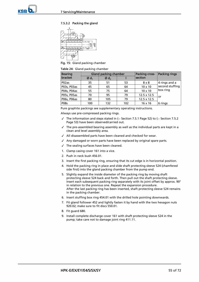
7.5.3.2 Packing the gland
s
l
d1
d2
Fig. 15: Gland packing chamber
Table 24: Gland packing chamber
Bearingbracket
Gland packing chamber Packing cross-section
Packing ringsØ d1 Ø d2 l
P02as 35 51 53 8 x 8 4 rings and asecond stuffingbox ring
or
6 rings
P03s, P03as 45 65 64 10 x 10P04s, P04as 55 75 64 10 x 10P05s, P05as 70 95 79 12.5 x 12.5P06s, P06as 80 105 79 12.5 x 12.5P08s 100 132 102 16 x 16
Pure graphite packings see supplementary operating instructions.
Always use pre-compressed packing rings.
✓ The information and steps stated in (⇨ Section 7.5.1 Page 52) to (⇨ Section 7.5.2Page 53) have been observed/carried out.
✓ The pre-assembled bearing assembly as well as the individual parts are kept in aclean and level assembly area.
✓ All disassembled parts have been cleaned and checked for wear.
✓ Any damaged or worn parts have been replaced by original spare parts.
✓ The sealing surfaces have been cleaned.
1. Clamp casing cover 161 into a vice.
2. Push in neck bush 456.01.
3. Insert the first packing ring, ensuring that its cut edge is in horizontal position.
4. Hold the packing ring in place and slide shaft protecting sleeve 524 (chamferedside first) into the gland packing chamber from the pump end.
5. Slightly expand the inside diameter of the packing ring by moving shaftprotecting sleeve 524 back and forth. Then pull out the shaft protecting sleeve.Insert each subsequent packing ring separately with its joint offset by approx. 90°in relation to the previous one. Repeat the expansion procedure. After the last packing ring has been inserted, shaft protecting sleeve 524 remainsin the packing chamber.
6. Insert stuffing box ring 454.01 with the drilled hole pointing downwards.
7. Fit gland follower 452 and lightly fasten it by hand with the two hexagon nuts920.02; make sure to fit discs 550.01.
8. Fit guard 680.
9. Install complete discharge cover 161 with shaft protecting sleeve 524 in thepump; take care not to damage joint ring 411.11.
7 Servicing/Maintenance
HPK-E/EX/EY/E4/S/SX/SY 55 of 72
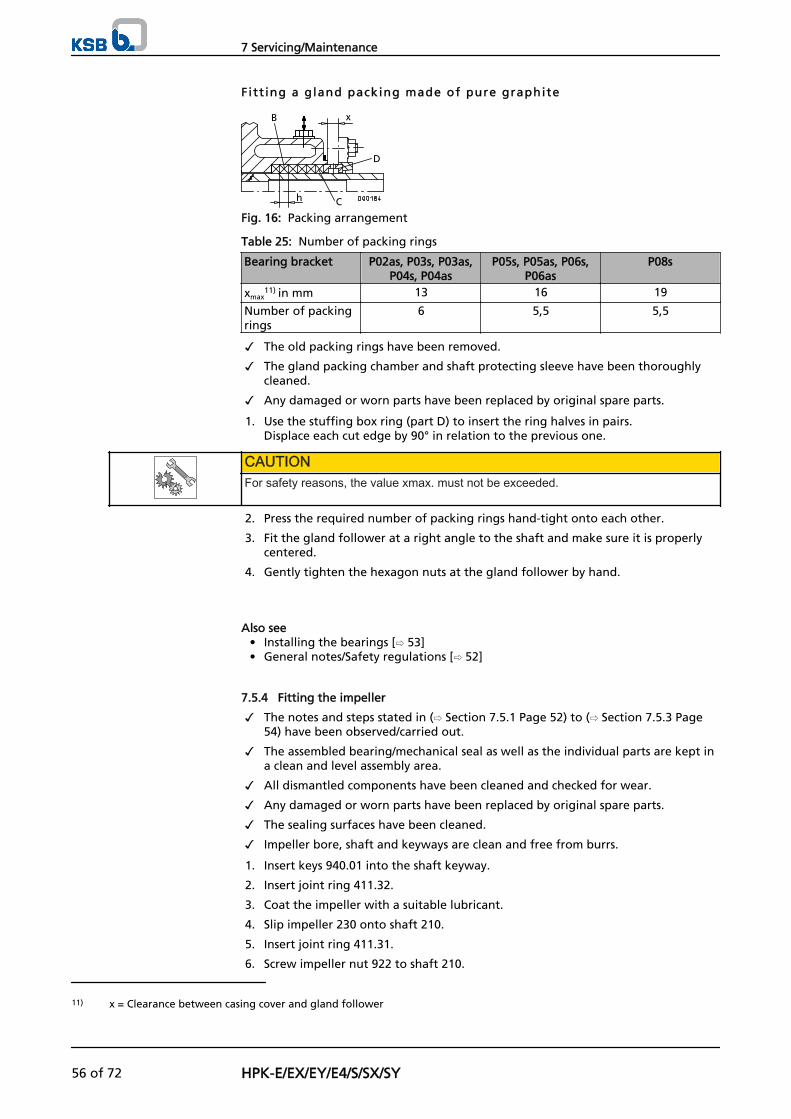
Fitt ing a gland packing made of pure graphite
B
D
C
x
h
Fig. 16: Packing arrangement
Table 25: Number of packing rings
Bearing bracket P02as, P03s, P03as,P04s, P04as
P05s, P05as, P06s,P06as
P08s
xmax11) in mm 13 16 19
Number of packingrings
6 5,5 5,5
✓ The old packing rings have been removed.
✓ The gland packing chamber and shaft protecting sleeve have been thoroughlycleaned.
✓ Any damaged or worn parts have been replaced by original spare parts.
1. Use the stuffing box ring (part D) to insert the ring halves in pairs.Displace each cut edge by 90° in relation to the previous one.
CAUTIONFor safety reasons, the value xmax. must not be exceeded.
2. Press the required number of packing rings hand-tight onto each other.
3. Fit the gland follower at a right angle to the shaft and make sure it is properlycentered.
4. Gently tighten the hexagon nuts at the gland follower by hand.
Also see• Installing the bearings [⇨ 53]• General notes/Safety regulations [⇨ 52]
7.5.4 Fitting the impeller
✓ The notes and steps stated in (⇨ Section 7.5.1 Page 52) to (⇨ Section 7.5.3 Page54) have been observed/carried out.
✓ The assembled bearing/mechanical seal as well as the individual parts are kept ina clean and level assembly area.
✓ All dismantled components have been cleaned and checked for wear.
✓ Any damaged or worn parts have been replaced by original spare parts.
✓ The sealing surfaces have been cleaned.
✓ Impeller bore, shaft and keyways are clean and free from burrs.
1. Insert keys 940.01 into the shaft keyway.
2. Insert joint ring 411.32.
3. Coat the impeller with a suitable lubricant.
4. Slip impeller 230 onto shaft 210.
5. Insert joint ring 411.31.
6. Screw impeller nut 922 to shaft 210.
11) x = Clearance between casing cover and gland follower
7 Servicing/Maintenance
56 of 72 HPK-E/EX/EY/E4/S/SX/SY
7.5.5 Fitting the back pull-out unit
WARNINGBack pull-out unit tipping overRisk of squashing hands and feet!
▷ Suspend or support the bearing bracket at the pump end.
✓ The notes and steps stated in (⇨ Section 7.5.1 Page 52) to (⇨ Section 7.5.4 Page56) have been observed/carried out.
✓ Any damaged or worn parts have been replaced by original spare parts.
✓ The sealing surfaces have been cleaned.
✓ For back pull-out units without coupling, install the coupling in accordance withthe manufacturer's instructions.
1. If required, prevent the back pull-out unit from tipping over, e.g. by suspendingor supporting it. Then push it into volute casing 102 with new gasket 411.10.
2. Tighten nut 920.01 at the volute casing.
3. Fasten support foot 183 to the baseplate with a foundation bolt.
7.5.6 Mounting the motor
NOTESteps 1 and 2 do not apply to versions with spacer-type coupling.
1. Shift the motor to connect it to the pump via the coupling.
2. Fasten the motor to the baseplate.
3. Align the pump. (⇨ Section 5.7 Page 30)
4. Connect the motor to the power supply (refer to manufacturer's productliterature).
7.6 Tightening torques
7.6.1 Tightening torques for volute casing/bearing bracket bolts
Use a torque wrench to tighten the screwed connections (902.02/920.01) between thevolute casing and the bearing bracket lantern.
Table 26: Tightening torques for screwed connections
Material ofstud/hex.nut
C35E+Qt/C 35 A4-70/A4-70 1.7709+QT/1.7258+QT 1.6772/1.6722
Stamp onstud/hex.nut12)
YK/Y A4-70/A4-70 GA/G MM/MM(M3k)Tightening torques [Nm]
Brand-new
threads1
3)
-15%14)
-20%14)
Brand-new
threads1
3)
-15%14)
-20%14)
Brand-new
threads1
3)
-15%14)
-20%14)
Brand-new
threads1
3)
-15%14)
-20%14)
M10 - - - 30 25.5 24 47 39.9 37.6 - - -M12 40 34 32 55 46.7 44 80 68 64 130 110.5 104M16 100 85 80 155 131.7 124 190 161.5 152 320 272.0 256M20 - - - 200 170 160 330 280.5 264 620 572.0 496
12) Treat unstamped screwed connections like material combination C35/E+QT/C 35.13) These values are determined on the basis of a friction coefficient μ = 0.12.14) After repeated tightening of the threads and in case of good lubrication the values shall be reduced by 15 to 20 %.
7 Servicing/Maintenance
HPK-E/EX/EY/E4/S/SX/SY 57 of 72
7.6.2 Tightening torques for the impeller nut
Observe the following tightening torques for the impeller nut (922):
Table 27: Tightening torques for the impeller nut
Bearing bracket Tightening torque[Nm]
WAF [mm]
P02as 55 22P03s, P03as 125 27P04s, P04as 200 32P05s, P05as 300 41P06s, P06as 520 55P08s 1000 60
Re-tighten the impeller nut some 20 to 30 minutes after assembly.
7.7 Spare parts stock
7.7.1 Ordering spare parts
Always quote the following data when ordering replacement or spare parts:
▪ Type series
▪ Pump size
▪ KSB order number
▪ Material variant
▪ Year of construction
Refer to the name plate for all data.
Also supply the following data:
▪ Part description
▪ Part No.
▪ Quantity of spare parts
▪ Shipping address
▪ Mode of dispatch (freight, mail, express freight, air freight)
Refer to the general assembly drawing for part numbers and descriptions.
7.7.2 Recommended spare parts stock for 2 years' operation to DIN 24296
Table 28: Quantity of spare parts for recommended spare parts stock
Part No. Description Number of pumps (including stand-by pumps)2 3 4 5 6 and 7 8 and 9 10 and
more210 Shaft 1 1 1 2 2 2 20 %230 Impeller 1 1 1 2 2 2 20 %320.02 Angular contact ball bearing
(set)1 1 2 2 2 3 25 %
322.01 Cylindrical roller bearing 1 1 2 2 2 3 25 %502.01 Casing wear ring 2 2 2 3 3 4 50 %524.01 Shaft protecting sleeve 2 2 2 3 3 4 50 %- Gaskets for pump casing (set) 4 6 8 8 9 12 150 %- Torque-transmitting coupling
elements (set)1 1 2 2 3 4 30 %
For variants with mechanical seal:433 Mechanical seal complete 1 1 2 2 2 3 25 %For variants with gland packing:456.01 Neck bush 1 1 2 2 2 3 30 %461.01 Gland packing (set) 4 4 6 6 6 8 100 %
7 Servicing/Maintenance
58 of 72 HPK-E/EX/EY/E4/S/SX/SY
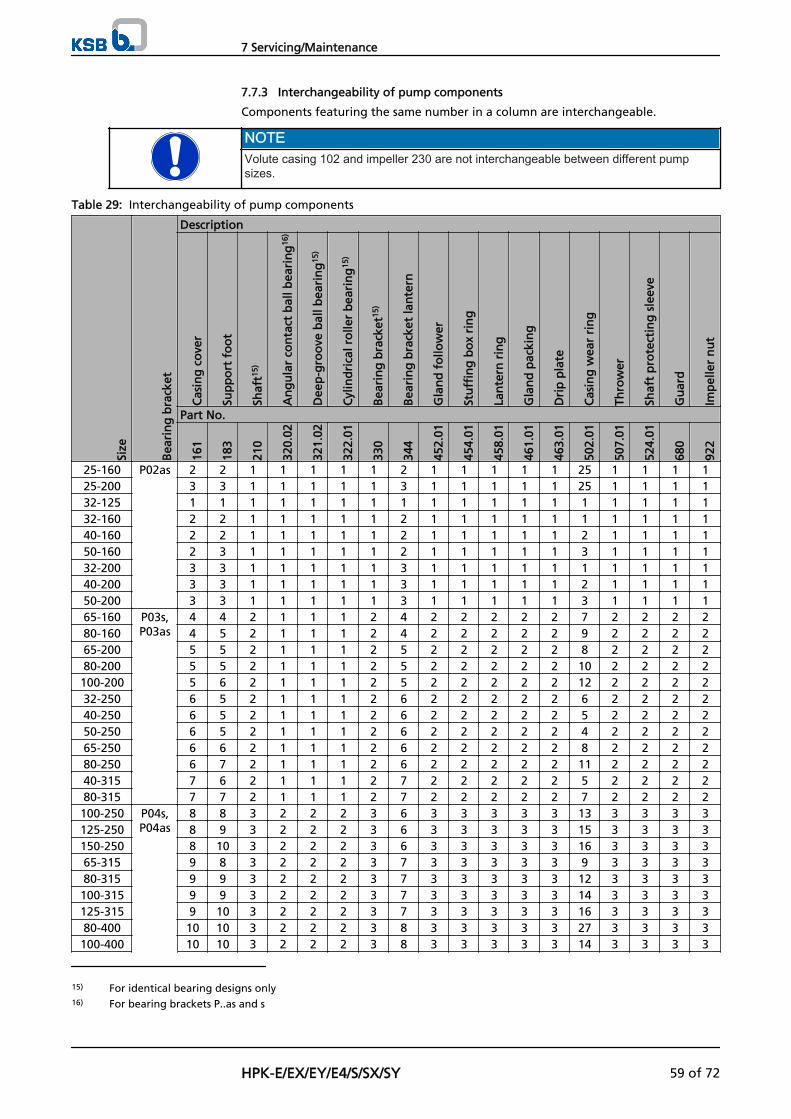
7.7.3 Interchangeability of pump components
Components featuring the same number in a column are interchangeable.
NOTEVolute casing 102 and impeller 230 are not interchangeable between different pumpsizes.
Table 29: Interchangeability of pump components
Size
Bea
rin
g b
rack
et
Description
Cas
ing
co
ver
Sup
po
rt f
oo
t
Shaf
t15)
An
gu
lar
con
tact
bal
l bea
rin
g16
)
Dee
p-g
roo
ve b
all b
eari
ng
15)
Cyl
ind
rica
l ro
ller
bea
rin
g15
)
Bea
rin
g b
rack
et15
)
Bea
rin
g b
rack
et la
nte
rn
Gla
nd
fo
llow
er
Stu
ffin
g b
ox
rin
g
Lan
tern
rin
g
Gla
nd
pac
kin
g
Dri
p p
late
Cas
ing
wea
r ri
ng
Thro
wer
Shaf
t p
rote
ctin
g s
leev
e
Gu
ard
Imp
elle
r n
ut
Part No.
161
183
210
320.
02
321.
02
322.
01
330
344
452.
01
454.
01
458.
01
461.
01
463.
01
502.
01
507.
01
524.
01
680
922
25-160 P02as 2 2 1 1 1 1 1 2 1 1 1 1 1 25 1 1 1 125-200 3 3 1 1 1 1 1 3 1 1 1 1 1 25 1 1 1 132-125 1 1 1 1 1 1 1 1 1 1 1 1 1 1 1 1 1 132-160 2 2 1 1 1 1 1 2 1 1 1 1 1 1 1 1 1 140-160 2 2 1 1 1 1 1 2 1 1 1 1 1 2 1 1 1 150-160 2 3 1 1 1 1 1 2 1 1 1 1 1 3 1 1 1 132-200 3 3 1 1 1 1 1 3 1 1 1 1 1 1 1 1 1 140-200 3 3 1 1 1 1 1 3 1 1 1 1 1 2 1 1 1 150-200 3 3 1 1 1 1 1 3 1 1 1 1 1 3 1 1 1 165-160 P03s,
P03as4 4 2 1 1 1 2 4 2 2 2 2 2 7 2 2 2 2
80-160 4 5 2 1 1 1 2 4 2 2 2 2 2 9 2 2 2 265-200 5 5 2 1 1 1 2 5 2 2 2 2 2 8 2 2 2 280-200 5 5 2 1 1 1 2 5 2 2 2 2 2 10 2 2 2 2100-200 5 6 2 1 1 1 2 5 2 2 2 2 2 12 2 2 2 232-250 6 5 2 1 1 1 2 6 2 2 2 2 2 6 2 2 2 240-250 6 5 2 1 1 1 2 6 2 2 2 2 2 5 2 2 2 250-250 6 5 2 1 1 1 2 6 2 2 2 2 2 4 2 2 2 265-250 6 6 2 1 1 1 2 6 2 2 2 2 2 8 2 2 2 280-250 6 7 2 1 1 1 2 6 2 2 2 2 2 11 2 2 2 240-315 7 6 2 1 1 1 2 7 2 2 2 2 2 5 2 2 2 280-315 7 7 2 1 1 1 2 7 2 2 2 2 2 7 2 2 2 2100-250 P04s,
P04as8 8 3 2 2 2 3 6 3 3 3 3 3 13 3 3 3 3
125-250 8 9 3 2 2 2 3 6 3 3 3 3 3 15 3 3 3 3150-250 8 10 3 2 2 2 3 6 3 3 3 3 3 16 3 3 3 365-315 9 8 3 2 2 2 3 7 3 3 3 3 3 9 3 3 3 380-315 9 9 3 2 2 2 3 7 3 3 3 3 3 12 3 3 3 3100-315 9 9 3 2 2 2 3 7 3 3 3 3 3 14 3 3 3 3125-315 9 10 3 2 2 2 3 7 3 3 3 3 3 16 3 3 3 380-400 10 10 3 2 2 2 3 8 3 3 3 3 3 27 3 3 3 3100-400 10 10 3 2 2 2 3 8 3 3 3 3 3 14 3 3 3 3
15) For identical bearing designs only16) For bearing brackets P..as and s
7 Servicing/Maintenance
HPK-E/EX/EY/E4/S/SX/SY 59 of 72
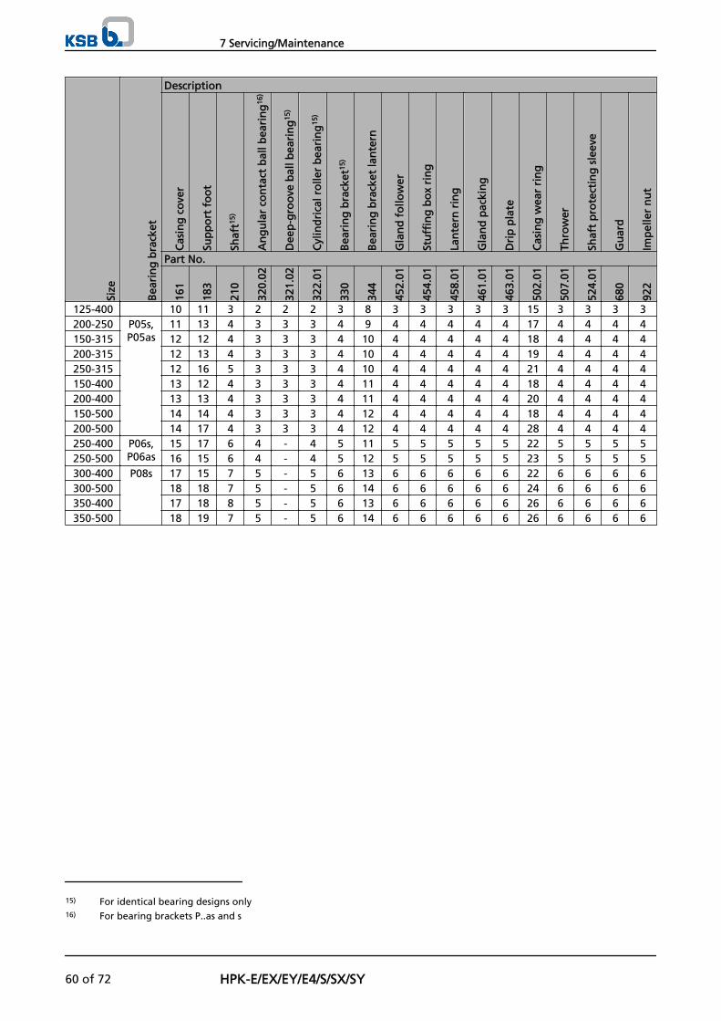
Size
Bea
rin
g b
rack
et
Description
Cas
ing
co
ver
Sup
po
rt f
oo
t
Shaf
t15)
An
gu
lar
con
tact
bal
l bea
rin
g16
)
Dee
p-g
roo
ve b
all b
eari
ng
15)
Cyl
ind
rica
l ro
ller
bea
rin
g15
)
Bea
rin
g b
rack
et15
)
Bea
rin
g b
rack
et la
nte
rn
Gla
nd
fo
llow
er
Stu
ffin
g b
ox
rin
g
Lan
tern
rin
g
Gla
nd
pac
kin
g
Dri
p p
late
Cas
ing
wea
r ri
ng
Thro
wer
Shaf
t p
rote
ctin
g s
leev
e
Gu
ard
Imp
elle
r n
ut
Part No.
161
183
210
320.
02
321.
02
322.
01
330
344
452.
01
454.
01
458.
01
461.
01
463.
01
502.
01
507.
01
524.
01
680
922
125-400 10 11 3 2 2 2 3 8 3 3 3 3 3 15 3 3 3 3200-250 P05s,
P05as11 13 4 3 3 3 4 9 4 4 4 4 4 17 4 4 4 4
150-315 12 12 4 3 3 3 4 10 4 4 4 4 4 18 4 4 4 4200-315 12 13 4 3 3 3 4 10 4 4 4 4 4 19 4 4 4 4250-315 12 16 5 3 3 3 4 10 4 4 4 4 4 21 4 4 4 4150-400 13 12 4 3 3 3 4 11 4 4 4 4 4 18 4 4 4 4200-400 13 13 4 3 3 3 4 11 4 4 4 4 4 20 4 4 4 4150-500 14 14 4 3 3 3 4 12 4 4 4 4 4 18 4 4 4 4200-500 14 17 4 3 3 3 4 12 4 4 4 4 4 28 4 4 4 4250-400 P06s,
P06as15 17 6 4 - 4 5 11 5 5 5 5 5 22 5 5 5 5
250-500 16 15 6 4 - 4 5 12 5 5 5 5 5 23 5 5 5 5300-400 P08s 17 15 7 5 - 5 6 13 6 6 6 6 6 22 6 6 6 6300-500 18 18 7 5 - 5 6 14 6 6 6 6 6 24 6 6 6 6350-400 17 18 8 5 - 5 6 13 6 6 6 6 6 26 6 6 6 6350-500 18 19 7 5 - 5 6 14 6 6 6 6 6 26 6 6 6 6
15) For identical bearing designs only16) For bearing brackets P..as and s
7 Servicing/Maintenance
60 of 72 HPK-E/EX/EY/E4/S/SX/SY
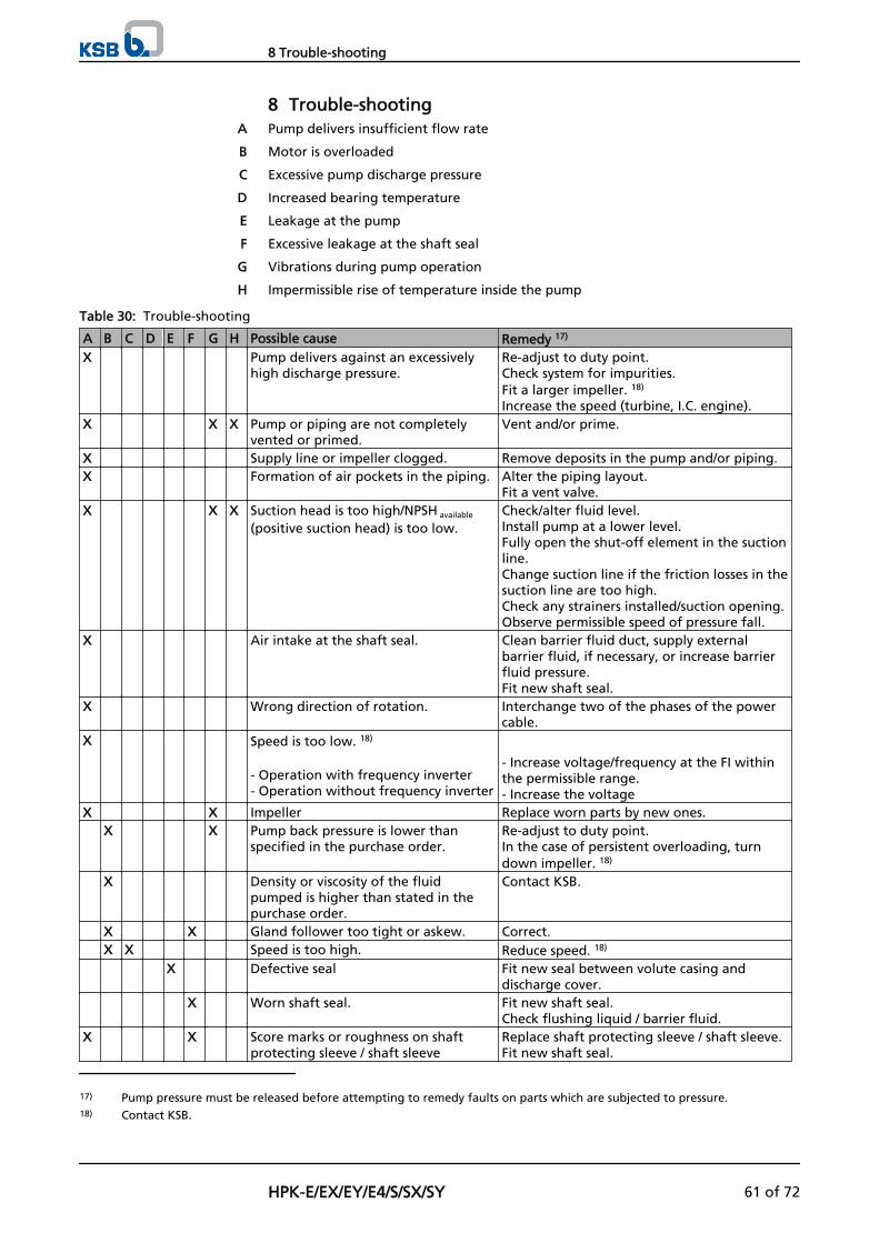
8 Trouble-shootingPump delivers insufficient flow rate
Motor is overloaded
Excessive pump discharge pressure
Increased bearing temperature
Leakage at the pump
Excessive leakage at the shaft seal
Vibrations during pump operation
Impermissible rise of temperature inside the pump
Table 30: Trouble-shooting
A B C D E F G H Possible cause Remedy 17)
X Pump delivers against an excessivelyhigh discharge pressure.
Re-adjust to duty point.Check system for impurities.Fit a larger impeller. 18)
Increase the speed (turbine, I.C. engine).X X X Pump or piping are not completely
vented or primed.Vent and/or prime.
X Supply line or impeller clogged. Remove deposits in the pump and/or piping.X Formation of air pockets in the piping. Alter the piping layout.
Fit a vent valve.X X X Suction head is too high/NPSH available
(positive suction head) is too low.Check/alter fluid level.Install pump at a lower level.Fully open the shut-off element in the suctionline.Change suction line if the friction losses in thesuction line are too high.Check any strainers installed/suction opening.Observe permissible speed of pressure fall.
X Air intake at the shaft seal. Clean barrier fluid duct, supply externalbarrier fluid, if necessary, or increase barrierfluid pressure.Fit new shaft seal.
X Wrong direction of rotation. Interchange two of the phases of the powercable.
X Speed is too low. 18)
- Operation with frequency inverter- Operation without frequency inverter
- Increase voltage/frequency at the FI withinthe permissible range.- Increase the voltage
X X Impeller Replace worn parts by new ones. X X Pump back pressure is lower than
specified in the purchase order.Re-adjust to duty point.In the case of persistent overloading, turndown impeller. 18)
X Density or viscosity of the fluidpumped is higher than stated in thepurchase order.
Contact KSB.
X X Gland follower too tight or askew. Correct. X X Speed is too high. Reduce speed. 18)
X Defective seal Fit new seal between volute casing anddischarge cover.
X Worn shaft seal. Fit new shaft seal.Check flushing liquid / barrier fluid.
X X Score marks or roughness on shaftprotecting sleeve / shaft sleeve
Replace shaft protecting sleeve / shaft sleeve.Fit new shaft seal.
A
B
C
D
E
F
G
H
17) Pump pressure must be released before attempting to remedy faults on parts which are subjected to pressure.18) Contact KSB.
8 Trouble-shooting
HPK-E/EX/EY/E4/S/SX/SY 61 of 72
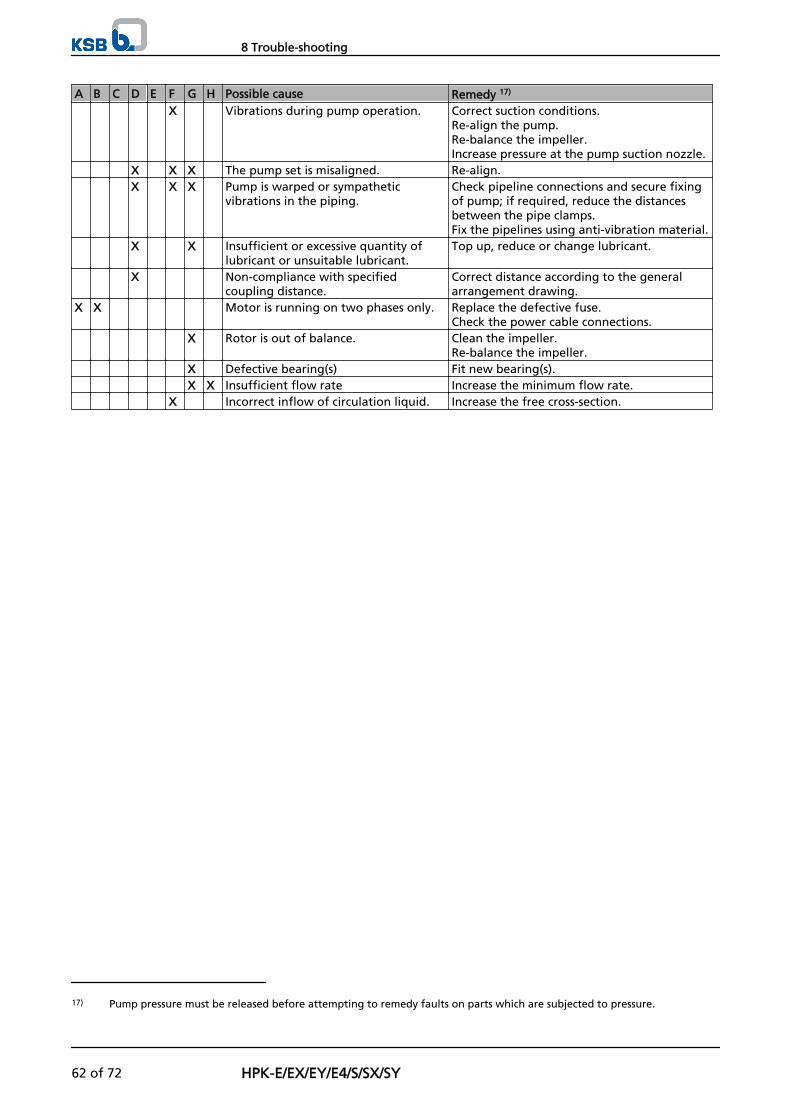
A B C D E F G H Possible cause Remedy 17)
X Vibrations during pump operation. Correct suction conditions.Re-align the pump.Re-balance the impeller.Increase pressure at the pump suction nozzle.
X X X The pump set is misaligned. Re-align. X X X Pump is warped or sympathetic
vibrations in the piping.Check pipeline connections and secure fixingof pump; if required, reduce the distancesbetween the pipe clamps.Fix the pipelines using anti-vibration material.
X X Insufficient or excessive quantity oflubricant or unsuitable lubricant.
Top up, reduce or change lubricant.
X Non-compliance with specifiedcoupling distance.
Correct distance according to the generalarrangement drawing.
X X Motor is running on two phases only. Replace the defective fuse.Check the power cable connections.
X Rotor is out of balance. Clean the impeller.Re-balance the impeller.
X Defective bearing(s) Fit new bearing(s). X X Insufficient flow rate Increase the minimum flow rate. X Incorrect inflow of circulation liquid. Increase the free cross-section.
17) Pump pressure must be released before attempting to remedy faults on parts which are subjected to pressure.
8 Trouble-shooting
62 of 72 HPK-E/EX/EY/E4/S/SX/SY
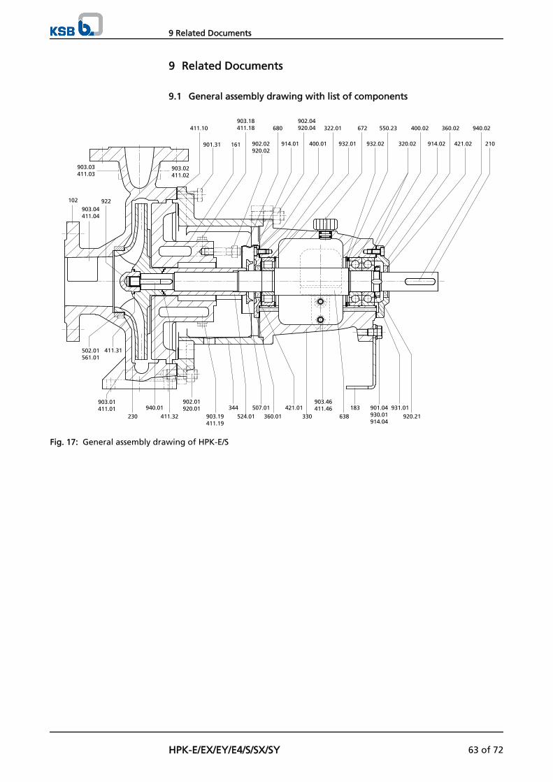
9 Related Documents
9.1 General assembly drawing with list of components
411.10
901.31 161
680
914.01 400.01
322.01
932.01
672
932.02
550.23
320.02
400.02
914.02
360.02
421.02
940.02
210
903.18411.18
902.02920.02
902.04920.04
903.02411.02
903.03411.03
230
940.01
411.32
902.01920.01
903.19411.19
344
524.01
507.01
360.01
421.01
330
903.46411.46
638
183 901.04930.01914.04
931.01
920.21
903.01411.01
102 922903.04411.04
411.31502.01561.01
Fig. 17: General assembly drawing of HPK-E/S
9 Related Documents
HPK-E/EX/EY/E4/S/SX/SY 63 of 72
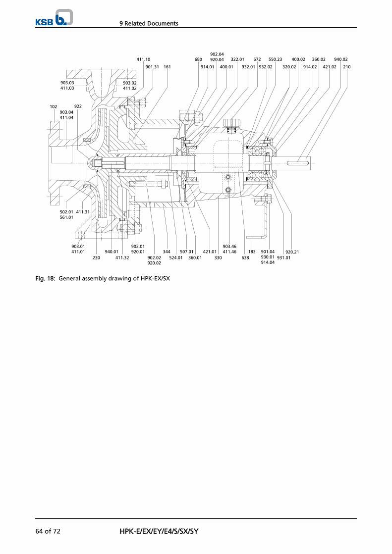
411.10
901.31 161
680
914.01
902.04920.04
400.01
322.01
932.01
672
932.02
550.23
320.02
400.02
914.02
360.02
421.02
940.02
210
903.02411.02
903.03411.03
102 922903.04411.04
411.31502.01561.01
903.01411.01
230940.01
411.32
902.01920.01
902.02920.02
344524.01
507.01360.01
421.01330
903.46411.46
638183 901.04
930.01914.04
931.01920.21
Fig. 18: General assembly drawing of HPK-EX/SX
9 Related Documents
64 of 72 HPK-E/EX/EY/E4/S/SX/SY
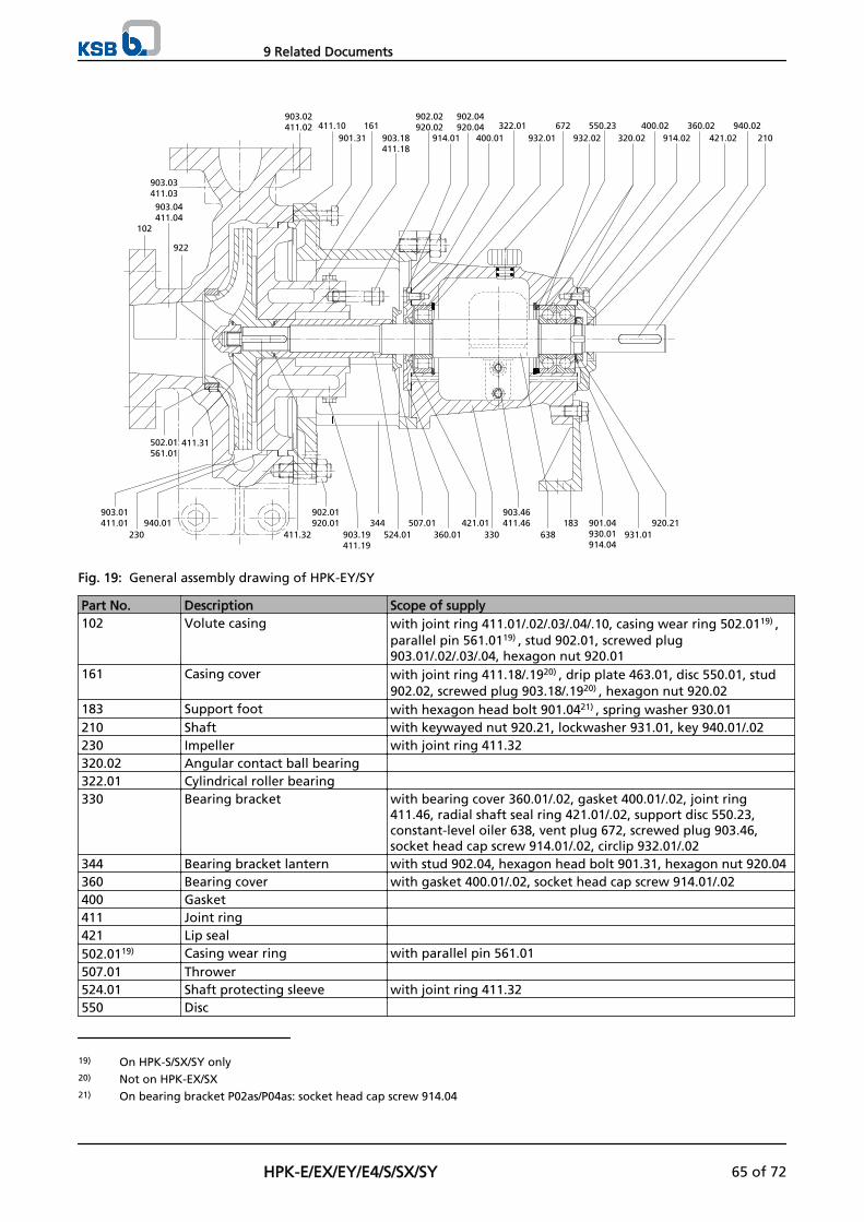
411.10901.31
161903.18411.18
902.02920.02
914.01
902.04920.04
400.01322.01
932.01672
932.02550.23
320.02400.02
914.02360.02
421.02940.02
210
903.02411.02
903.03411.03
903.04411.04
102
922
411.31502.01561.01
903.01411.01
230940.01
411.32
902.01920.01
903.19411.19
344524.01
507.01360.01
421.01330
903.46411.46
638183 901.04
930.01914.04
931.01920.21
Fig. 19: General assembly drawing of HPK-EY/SY
Part No. Description Scope of supply102 Volute casing with joint ring 411.01/.02/.03/.04/.10, casing wear ring 502.0119) ,
parallel pin 561.0119) , stud 902.01, screwed plug903.01/.02/.03/.04, hexagon nut 920.01
161 Casing cover with joint ring 411.18/.1920) , drip plate 463.01, disc 550.01, stud902.02, screwed plug 903.18/.1920) , hexagon nut 920.02
183 Support foot with hexagon head bolt 901.0421) , spring washer 930.01210 Shaft with keywayed nut 920.21, lockwasher 931.01, key 940.01/.02230 Impeller with joint ring 411.32320.02 Angular contact ball bearing 322.01 Cylindrical roller bearing 330 Bearing bracket with bearing cover 360.01/.02, gasket 400.01/.02, joint ring
411.46, radial shaft seal ring 421.01/.02, support disc 550.23,constant-level oiler 638, vent plug 672, screwed plug 903.46,socket head cap screw 914.01/.02, circlip 932.01/.02
344 Bearing bracket lantern with stud 902.04, hexagon head bolt 901.31, hexagon nut 920.04360 Bearing cover with gasket 400.01/.02, socket head cap screw 914.01/.02400 Gasket 411 Joint ring 421 Lip seal 502.0119) Casing wear ring with parallel pin 561.01507.01 Thrower 524.01 Shaft protecting sleeve with joint ring 411.32550 Disc
19) On HPK-S/SX/SY only20) Not on HPK-EX/SX21) On bearing bracket P02as/P04as: socket head cap screw 914.04
9 Related Documents
HPK-E/EX/EY/E4/S/SX/SY 65 of 72
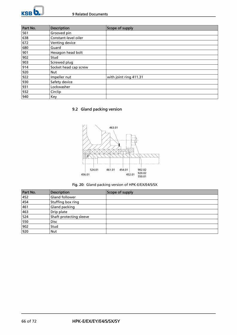
Part No. Description Scope of supply561 Grooved pin 638 Constant-level oiler 672 Venting device 680 Guard 901 Hexagon head bolt 902 Stud 903 Screwed plug 914 Socket head cap screw 920 Nut 922 Impeller nut with joint ring 411.31930 Safety device 931 Lockwasher 932 Circlip 940 Key
9.2 Gland packing version
463.01
456.01
524.01 461.01 454.01
452.01
902.02920.02550.01
Fig. 20: Gland packing version of HPK-E/EX/E4/S/SX
Part No. Description Scope of supply452 Gland follower 454 Stuffing box ring 461 Gland packing 463 Drip plate 524 Shaft protecting sleeve 550 Disc 902 Stud 920 Nut
9 Related Documents
66 of 72 HPK-E/EX/EY/E4/S/SX/SY
10 EC Declaration of Conformity
Manufacturer: KSB AktiengesellschaftJohann-Klein-Straße 9
67227 Frankenthal (Germany)
The manufacturer herewith declares that the pump/pump set:
HPK
KSB order number: ...................................................................................................
▪ is in conformity with the provisions of the following directives as applicable in their current version:
– EC Machinery Directive 2006/42/EC
The manufacturer also declares that
▪ the following harmonised international standards have been applied:
– ISO 12100-1/A1, ISO 12100-2/A1,
– ISO 14121-1,
– EN 809/A1
Pegnitz, 29 December 2009
...........................................................
Name
Function
Responsible for compiling the technical documentationKSB Aktiengesellschaft
Bahnhofplatz 1
91257 Pegnitz (Germany)
10 EC Declaration of Conformity
HPK-E/EX/EY/E4/S/SX/SY 67 of 72
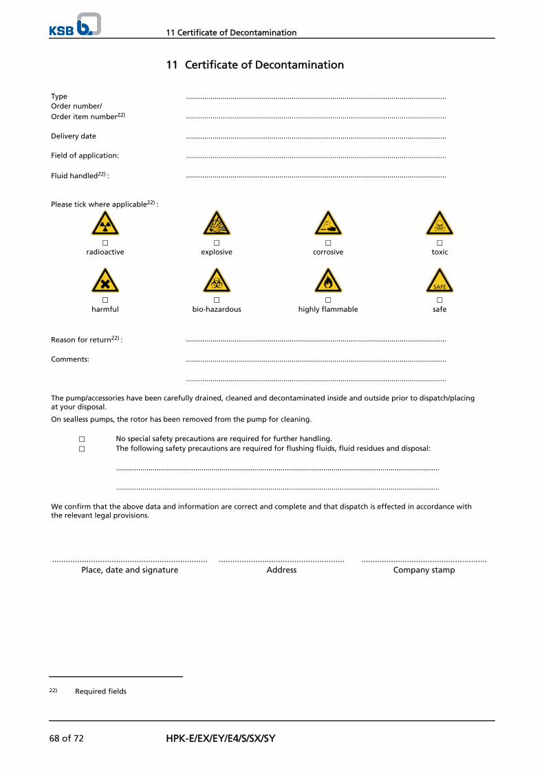
11 Certificate of Decontamination
Type ................................................................................................................................Order number/Order item number22) ................................................................................................................................ Delivery date ................................................................................................................................ Field of application: ................................................................................................................................ Fluid handled22) : ................................................................................................................................
Please tick where applicable22) :
⃞ ⃞ ⃞ ⃞radioactive explosive corrosive toxic
⃞ ⃞ ⃞ ⃞harmful bio-hazardous highly flammable safe
Reason for return22) : ................................................................................................................................ Comments: ................................................................................................................................ ................................................................................................................................ The pump/accessories have been carefully drained, cleaned and decontaminated inside and outside prior to dispatch/placingat your disposal.
On sealless pumps, the rotor has been removed from the pump for cleaning.
⃞ No special safety precautions are required for further handling.⃞ The following safety precautions are required for flushing fluids, fluid residues and disposal:
............................................................................................................................................................... ............................................................................................................................................................... We confirm that the above data and information are correct and complete and that dispatch is effected in accordance withthe relevant legal provisions.
.................................................................... ....................................................... .......................................................Place, date and signature Address Company stamp
22) Required fields
11 Certificate of Decontamination
68 of 72 HPK-E/EX/EY/E4/S/SX/SY
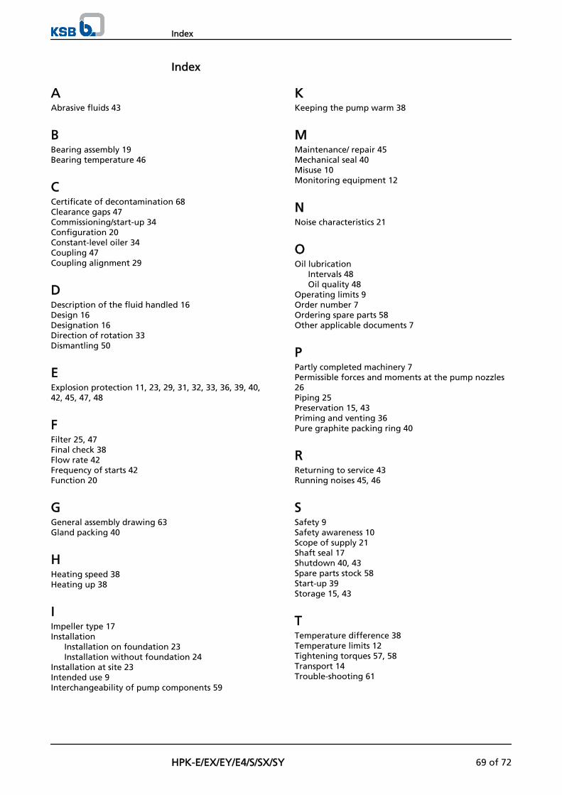
Index
AAbrasive fluids 43
BBearing assembly 19Bearing temperature 46
CCertificate of decontamination 68Clearance gaps 47Commissioning/start-up 34Configuration 20Constant-level oiler 34Coupling 47Coupling alignment 29
DDescription of the fluid handled 16Design 16Designation 16Direction of rotation 33Dismantling 50
EExplosion protection 11, 23, 29, 31, 32, 33, 36, 39, 40,42, 45, 47, 48
FFilter 25, 47Final check 38Flow rate 42Frequency of starts 42Function 20
GGeneral assembly drawing 63Gland packing 40
HHeating speed 38Heating up 38
IImpeller type 17Installation
Installation on foundation 23Installation without foundation 24
Installation at site 23Intended use 9Interchangeability of pump components 59
KKeeping the pump warm 38
MMaintenance/ repair 45Mechanical seal 40Misuse 10Monitoring equipment 12
NNoise characteristics 21
OOil lubrication
Intervals 48Oil quality 48
Operating limits 9Order number 7Ordering spare parts 58Other applicable documents 7
PPartly completed machinery 7Permissible forces and moments at the pump nozzles26Piping 25Preservation 15, 43Priming and venting 36Pure graphite packing ring 40
RReturning to service 43Running noises 45, 46
SSafety 9Safety awareness 10Scope of supply 21Shaft seal 17Shutdown 40, 43Spare parts stock 58Start-up 39Storage 15, 43
TTemperature difference 38Temperature limits 12Tightening torques 57, 58Transport 14Trouble-shooting 61
Index
HPK-E/EX/EY/E4/S/SX/SY 69 of 72
WWater cooling 37
Index
70 of 72 HPK-E/EX/EY/E4/S/SX/SY


KSB AktiengesellschaftP.O. Box 1361 • 91253 Pegnitz • Bahnhofplatz 1, 91257 Pegnitz (Germany) Tel. +49 9241 71-0 • Fax +49 9241 71-1793www.ksb.com
1121
.8/2
-10