Embed Size (px)
Citation preview
Material Challenges and Suggestions for Pumps inHot Naphthenic Acid Containing Crude Oil Services
Aaron BurtonLead Field Engineer – Sulzer Pumps Services (US) Inc.
Ricky TrahanMechanical Inspector – Motiva Enterprises
slide 1
Material Challenges and Suggestions for Pumps inHot Naphthenic Acid Containing Crude Oil Services
Presenter and Co-Author Aaron BurtonLead Field Engineer – Sulzer Pumps Services (US) Inc.Tel: (281) 417-7104Email: [email protected]
Presenter and Co-Author Ricky TrahanMechanical Inspector – Motiva EnterprisesTel (409) 960-8733Email: [email protected]
Abstract:As the global demand for fuels continued to grow, refineries changed to accommodateheavier crude oils. Many of those heavier oils contained Naphthenic acid which posed furthercorrosion challenges at the high process temperatures required.
These challenges included moving from pump materials that are typically stable at hightemperatures, such as CA6NM, to less stable higher nickel stainless steels. Those have ahigher propensity to distort under high thermal stresses and have variable rates of thermalexpansion that increase with process temperature.
This case study lists the challenges and discuss the changes in material selection,dimensional stabilization procedures, machining methods and suggestions for changes toprocess start-up and shut-down procedures to improve reliability of the pumps.
slide 2
Problem Description
Single and Two Stage Between Bearing Pumps (BB2)
Vacuum Bottoms and Atmospheric Residue Services
High Temperature Operation – up to 360°C (681°F)
Potentially Corrosive Pumpage – Crude oil with Naphthenic Acids
Pump Construction – 317L Stainless Steel
Thermal transients for start-up and shut-down are very fast and enact highthermal stresses in the pump case and shaft, causing major distortion
Distortions due to thermal stresses resulted in rotor lock-up and extensiverepairs to return casing registers and fits to proper sizes
MTBR has been as little as 6 months or less
Repairs are long leadtime and very expensive
slide 3
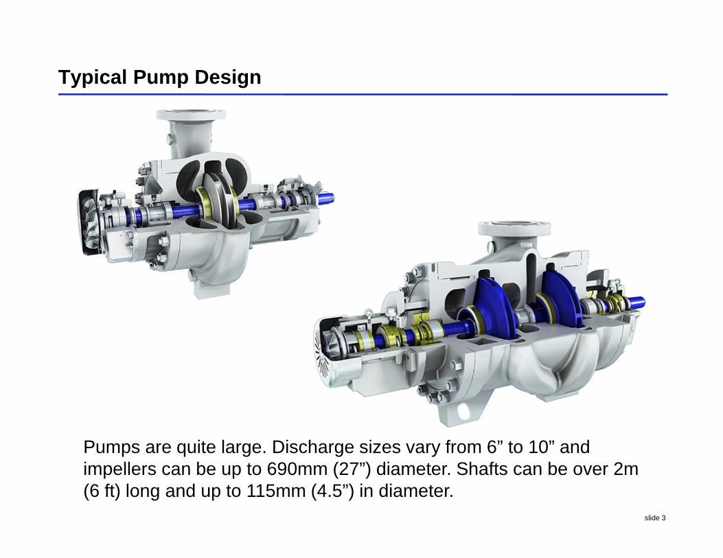
Typical Pump Design
Pumps are quite large. Discharge sizes vary from 6” to 10” andimpellers can be up to 690mm (27”) diameter. Shafts can be over 2m(6 ft) long and up to 115mm (4.5”) in diameter.
slide 4
As-Purchased Pump Materials of Construction
Pump Case – 317LSS (ASTM A351 Gr. CG-3M)
Standard solution annealed material
Impeller – 317LSS (ASTM A351 Gr. CG-3M)
Standard solution annealed material
Shaft – 317LSS (ASTM A276 Type 317)
slide 5
Original Unit Start-Up and Shut-Down Procedures
The original heat up process:
Line up purge oil to the seal flush.
Open suction valve
Open all warm up lines and discharge line.
Allow pump to warm up to within 55oC (100°F) dT of running temp 260oC (500°F).
Problems with the original procedure:
Opening the suction first allowed the purge oil to travel into the suction of the sisterpump. That then flashed in the hot running pump and caused extreme cavitation.
There were no real steps to control or monitor the temperature rise in the pump.
The original procedure did not call for a cool down process.
The pump was simply shutdown; discharge, suction and seal flush valves were closed.
The pump was then flushed with 93°C (200°F) kerosene. After 2-4 hours of flushing thepump was then steamed to the vacuum tower for 8 hours.
The operator would then allow the pump to cool for 2-3 hours and perform a gas test.
If the gas test was bad they would repeat the steps until they got a good gas test.
This was normally repeated several times with the end result being a warped shaft.
slide 6
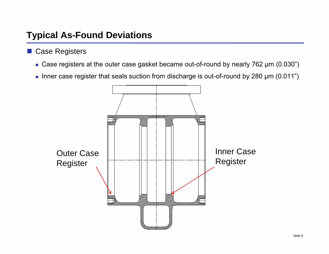
Typical As-Found Deviations
Case Registers
Case registers at the outer case gasket became out-of-round by nearly 762 μm (0.030”)
Inner case register that seals suction from discharge is out-of-round by 280 μm (0.011”)
Outer CaseRegister
Inner CaseRegister

slide 7
Typical As-Found Deviations
Case Cover Registers
Outer cover registers not grossly out of round
Inner cover registers out of round by 203 μm (0.008”)
Wear ring landing typically out of roundInner Register
Wear ringlanding
Outer Register
slide 8
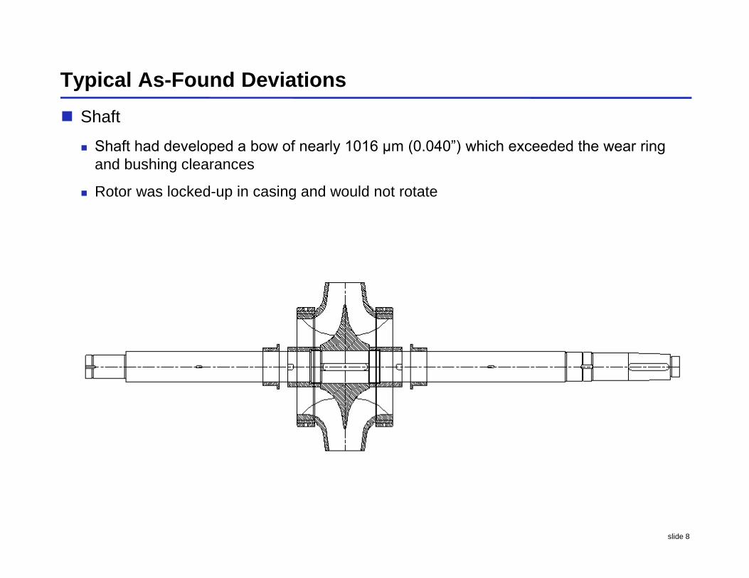
Typical As-Found Deviations
Shaft
Shaft had developed a bow of nearly 1016 μm (0.040”) which exceeded the wear ring and bushing clearances
Rotor was locked-up in casing and would not rotate
slide 9
Recommendations for Material Selection andManufacturing – Pump Shaft
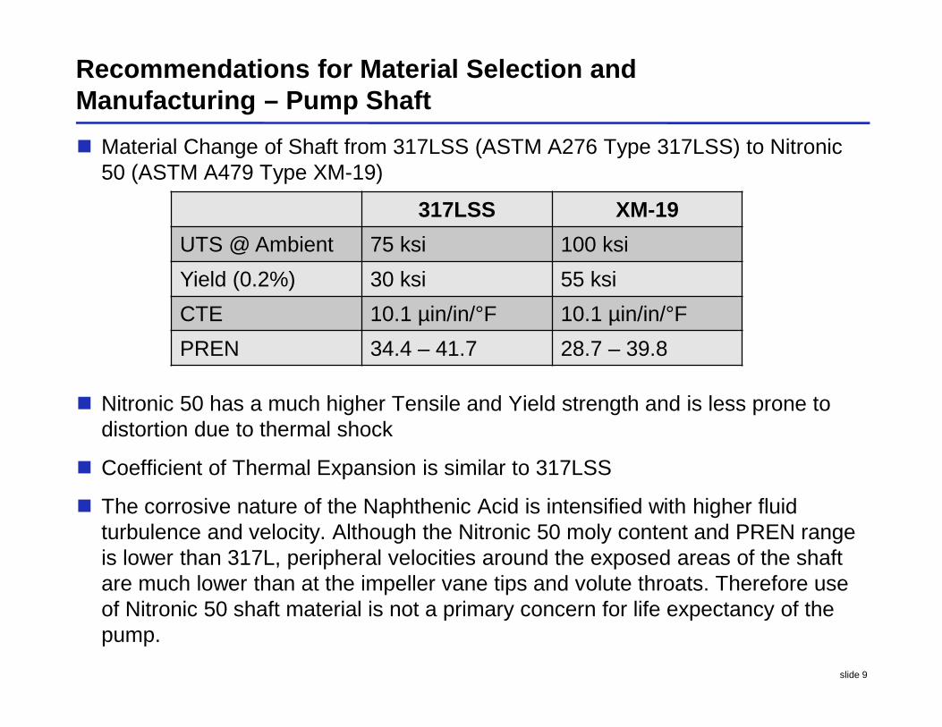
Material Change of Shaft from 317LSS (ASTM A276 Type 317LSS) to Nitronic50 (ASTM A479 Type XM-19)
Nitronic 50 has a much higher Tensile and Yield strength and is less prone todistortion due to thermal shock
Coefficient of Thermal Expansion is similar to 317LSS
The corrosive nature of the Naphthenic Acid is intensified with higher fluidturbulence and velocity. Although the Nitronic 50 moly content and PREN rangeis lower than 317L, peripheral velocities around the exposed areas of the shaftare much lower than at the impeller vane tips and volute throats. Therefore useof Nitronic 50 shaft material is not a primary concern for life expectancy of thepump.
317LSS XM-19
UTS @ Ambient 75 ksi 100 ksi
Yield (0.2%) 30 ksi 55 ksi
CTE 10.1 µin/in/°F 10.1 µin/in/°F
PREN 34.4 – 41.7 28.7 – 39.8
slide 10
Recommendations for Material Selection andManufacturing – Pump Shaft
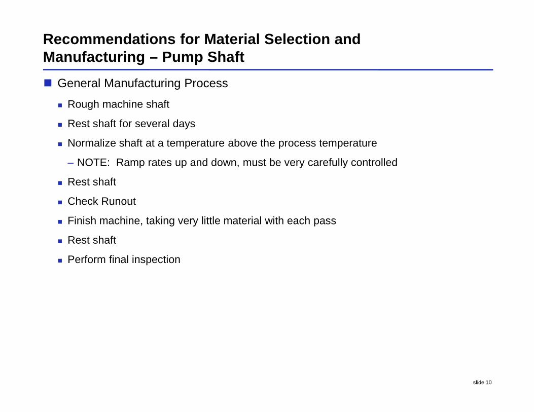
General Manufacturing Process
Rough machine shaft
Rest shaft for several days
Normalize shaft at a temperature above the process temperature
– NOTE: Ramp rates up and down, must be very carefully controlled
Rest shaft
Check Runout
Finish machine, taking very little material with each pass
Rest shaft
Perform final inspection
slide 11
Recommendations for Material Selection andManufacturing – Pump Case Components
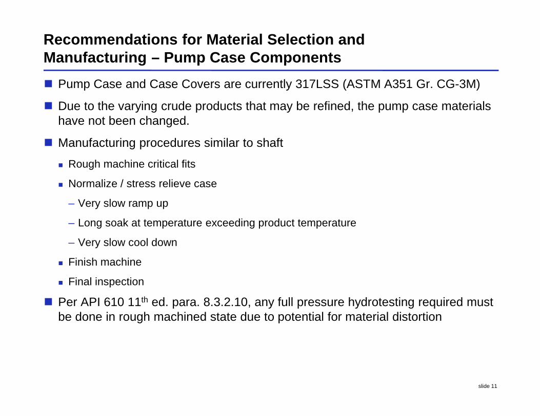
Pump Case and Case Covers are currently 317LSS (ASTM A351 Gr. CG-3M)
Due to the varying crude products that may be refined, the pump case materialshave not been changed.
Manufacturing procedures similar to shaft
Rough machine critical fits
Normalize / stress relieve case
– Very slow ramp up
– Long soak at temperature exceeding product temperature
– Very slow cool down
Finish machine
Final inspection
Per API 610 11th ed. para. 8.3.2.10, any full pressure hydrotesting required mustbe done in rough machined state due to potential for material distortion
slide 12
Changes in Processes for Start-up
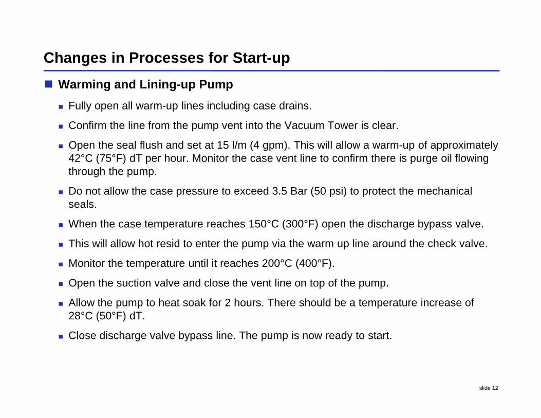
Warming and Lining-up Pump
Fully open all warm-up lines including case drains.
Confirm the line from the pump vent into the Vacuum Tower is clear.
Open the seal flush and set at 15 l/m (4 gpm). This will allow a warm-up of approximately42°C (75°F) dT per hour. Monitor the case vent line to confirm there is purge oil flowingthrough the pump.
Do not allow the case pressure to exceed 3.5 Bar (50 psi) to protect the mechanicalseals.
When the case temperature reaches 150°C (300°F) open the discharge bypass valve.
This will allow hot resid to enter the pump via the warm up line around the check valve.
Monitor the temperature until it reaches 200°C (400°F).
Open the suction valve and close the vent line on top of the pump.
Allow the pump to heat soak for 2 hours. There should be a temperature increase of28°C (50°F) dT.
Close discharge valve bypass line. The pump is now ready to start.
slide 13
Changes in Processes Shut-down
Cooling Pump for Shutdown and Repair.
Confirm all warm- up and vent lines are open and clear.
Confirm the seal flush is set at 15 l/m (4 gpm). Close the suction valve and allow the pumpto cool to 200°C (400°F).
At 200°C (400°F) close the discharge valve and continue cool down with the seal flush of15 l/m (4 gpm).
Have the coupling guard and spool removed. Install components required to turn pump.
At this point the pump is to be turned 1-1/2 turns per hour.
Flush with seal oil at 15 l/m (4 gpm) for 3 hours. This will cool the pump to 180°C (350°F).
Reduce the seal flush flow to 11 l/m (3 gpm) for 2 hours.
Reduce the flush flow to 8 l/m (2 gpm) for 2 hours. This will reduce the pump temperatureto around 150°C (300°F).
Reduce the seal flush flow to 4 l/m (1 gpm) for 2 hours. The pump temperature will bebelow 150°C (300°F). Close the seal flush and allow pump to cool to 120°C (250°F). Beginthe Kerosene flush.
After 12 hours of Kerosene flushing close valve and begin steaming the pump for 4 hours.At this point the pump is ready for repair work to begin.
slide 14
Results of Process and Manufacturing Changes
Case Register Runout
After implementation of the heat treatment and site process changes, register runoutsafter shut-down have measured significantly less.
– Prior to normalizing / stress relief procedure – 762 μm (0.030”) runout
– After normalizing / stress relief procedure – 254 μm (0.010”) max runout
Shaft Runout
Shafts that have been changed to Nitronic 50 material show no run-out at inspectionafter change in manufacturing procedures and site commissioning and decommissioningprocedures. They are reusable.
Shafts manufactured from 317L material that has been subjected to the samemanufacturing procedures and start-up and shut-down procedures show 25 μm (0.001”) runout max. They are reusable in many cases.
Prior to implementing the new procedures, pump would be locked-up at every sealmaintenance interval. Now it can be turned with little effort.