Embed Size (px)
Citation preview
Integrating Meraki Networks with
Cisco Identity Services Engine
Secure Access How-To guide series
Authors: Tim Abbott, Colin Lowenberg
Date: April 2016
Table of Contents
Introduction
Cisco Systems © 2016 Page 2
Compatibility Matrix
Overview
Components
Network Diagram
Meraki Wireless Network Configuration
Configure Meraki Wireless Group Policy
Add ISE as a RADIUS Server for Dot1x SSID
Add ISE as a RADIUS Server for Guest SSID
Add ISE as a RADIUS Server for Wireless MAB SSID
Meraki Wired Network Configuration
Add ISE as a RADIUS Server for Wired 802.1X
Apply Access Policy to Switch Ports
Meraki VPN Network Configuration
Configure Client VPN Access
ISE Configuration
Enable Policy Sets
Add Meraki Access Point as a Network Access Devices
Add Meraki Switch as a Network Access Device
Add Meraki Security Appliance as a Network Access Device
Add Meraki Cloud RADIUS Clients as Network Access Devices
Authorization Profiles
Allowed Protocols
ISE AAA Configuration
Cisco Systems © 2016 Page 3
Wireless Authentication Rule
Wireless 802.1X Authentication
Wireless MAB Authentication
Wireless Local Web Authentication
Wired 802.1X Authentication Rule
RA VPN Authentication Rule
Wireless 802.1X Authorization
Central Web Authentication (CWA) Examples
HotSpot Example
Self-Registered Guest Example
Sponsored Guest Guest Example
BYOD Enrollment Example
MDM Enrollment Example
Posture Assessment Example
Wireless LWA Authorization
Wired Authorization Policy
RA VPN Authorization
Profiling Considerations
Wireless Network Profiling
Wired Network Profiling

Cisco Systems © 2016 Page 4
Introduction This configuration example illustrates how to use Cisco Identity Services Engine (ISE) to authenticate users attempting access to Meraki wireless, wired, and VPN networks. ISE uses predefined Meraki Group Policies to assign network users an access policy based on group membership in Microsoft’s Active Directory (AD), Guest user credentials, or Endpoint information. The example uses the following Identity Groups: Employees, Contractors, Guests and Workstations. Using these groups, the document outlines the steps necessary to configure 802.1X, MAC Authentication Bypass (MAB), Local Web Authentication (LWA), Central Web Authentication (CWA), Remote Access (RA) VPN and Profiling where applicable. For the latest documentation please visit the Cisco Meraki documentation:
Compatibility Matrix
Feature MR Wireless Compatibility
MX Appliance Compatibility
MS Switch Compatibility Details
IEEE-802.1X Authentication Supported Supported Supported
MAC Authentication By-Pass Supported Not Supported Supported
Enforcement Supported Not Supported Not Supported Preconfigured Group policy (wireless).
Local Web Authentication Supported Not Supported Not Supported Local captive portals (wireless).
Device Profiling Supported Limited Support Limited Support RADIUS (Wired).
Device Posturing Supported Limited Support Limited Support Requires Inline Posture Node.
Guest (Hotspot, Self-register, Sponsored) Supported Limited Support Limited Support Guest VLAN (Wired).
Cisco Systems © 2016 Page 5
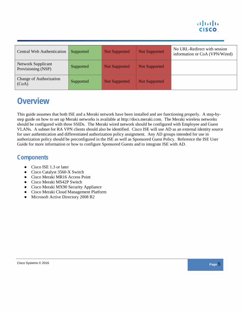
Central Web Authentication Supported Not Supported Not Supported No URL-Redirect with session information or CoA (VPN/Wired)
Network Supplicant Provisioning (NSP) Supported Not Supported Not Supported
Change of Authorization (CoA) Supported Not Supported Not Supported
Overview This guide assumes that both ISE and a Meraki network have been installed and are functioning properly. A step-by-step guide on how to set up Meraki networks is available at http://docs.meraki.com. The Meraki wireless networks should be configured with three SSIDs. The Meraki wired network should be configured with Employee and Guest VLANs. A subnet for RA VPN clients should also be identified. Cisco ISE will use AD as an external identity source for user authentication and differentiated authorization policy assignment. Any AD groups intended for use in authorization policy should be preconfigured in the ISE as well as Sponsored Guest Policy. Reference the ISE User Guide for more information or how to configure Sponsored Guests and to integrate ISE with AD.
Components ● Cisco ISE 1.3 or later ● Cisco Catalyst 3560-X Switch ● Cisco Meraki MR16 Access Point ● Cisco Meraki MS42P Switch ● Cisco Meraki MX90 Security Appliance ● Cisco Meraki Cloud Management Platform ● Microsoft Active Directory 2008 R2
Cisco Systems © 2016 Page 6
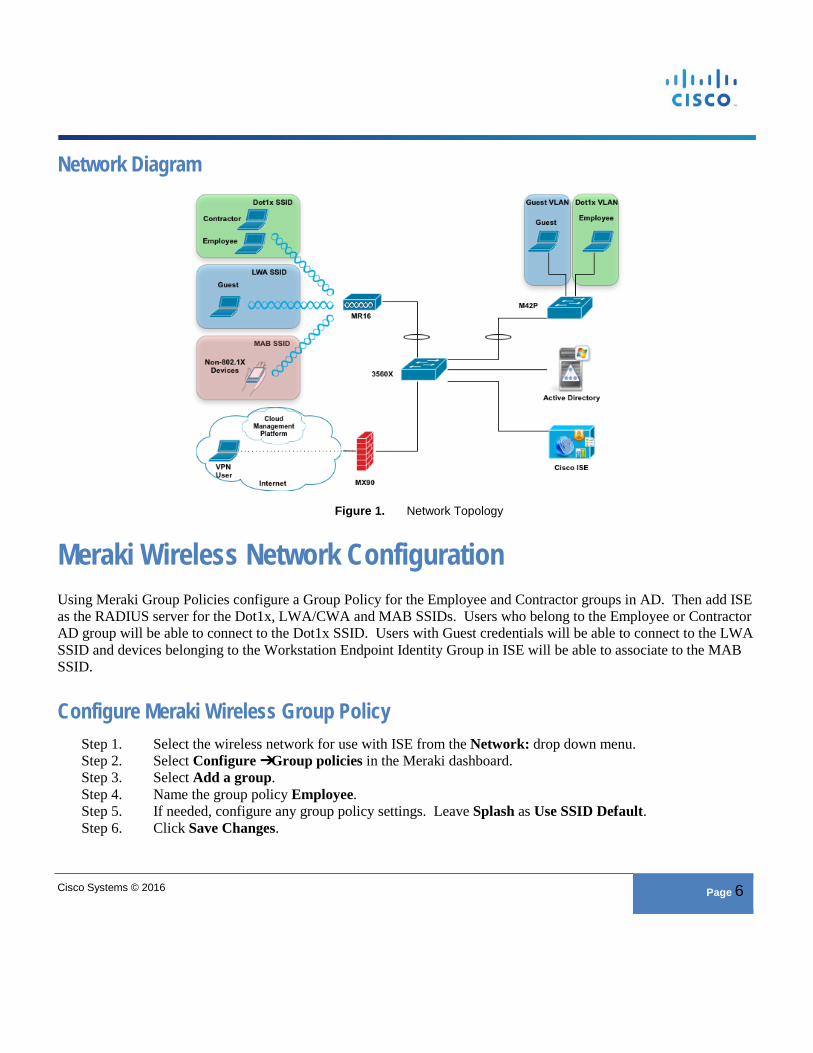
Network Diagram
Figure 1. Network Topology
Meraki Wireless Network Configuration Using Meraki Group Policies configure a Group Policy for the Employee and Contractor groups in AD. Then add ISE as the RADIUS server for the Dot1x, LWA/CWA and MAB SSIDs. Users who belong to the Employee or Contractor AD group will be able to connect to the Dot1x SSID. Users with Guest credentials will be able to connect to the LWA SSID and devices belonging to the Workstation Endpoint Identity Group in ISE will be able to associate to the MAB SSID.
Configure Meraki Wireless Group Policy Step 1. Select the wireless network for use with ISE from the Network: drop down menu. Step 2. Select Configure ➔Group policies in the Meraki dashboard. Step 3. Select Add a group. Step 4. Name the group policy Employee. Step 5. If needed, configure any group policy settings. Leave Splash as Use SSID Default. Step 6. Click Save Changes.
Cisco Systems © 2016 Page 7
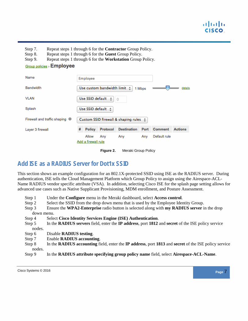
Step 7. Repeat steps 1 through 6 for the Contractor Group Policy. Step 8. Repeat steps 1 through 6 for the Guest Group Policy. Step 9. Repeat steps 1 through 6 for the Workstation Group Policy.
Figure 2. Meraki Group Policy
Add ISE as a RADIUS Server for Dot1x SSID This section shows an example configuration for an 802.1X-protected SSID using ISE as the RADIUS server. During authentication, ISE tells the Cloud Management Platform which Group Policy to assign using the Airespace-ACL-Name RADIUS vendor specific attribute (VSA). In addition, selecting Cisco ISE for the splash page setting allows for advanced use cases such as Native Supplicant Provisioning, MDM enrollment, and Posture Assessment.
Step 1 Under the Configure menu in the Meraki dashboard, select Access control. Step 2 Select the SSID from the drop down menu that is used by the Employee Identity Group. Step 3 Ensure the WPA2-Enterprise radio button is selected along with my RADIUS server in the drop
down menu. Step 4 Select Cisco Identity Services Engine (ISE) Authentication. Step 5 In the RADIUS servers field, enter the IP address, port 1812 and secret of the ISE policy service
nodes. Step 6 Disable RADIUS testing. Step 7 Enable RADIUS accounting. Step 8 In the RADIUS accounting field, enter the IP address, port 1813 and secret of the ISE policy service
nodes. Step 9 In the RADIUS attribute specifying group policy name field, select Airespace-ACL-Name.
Cisco Systems © 2016 Page 8
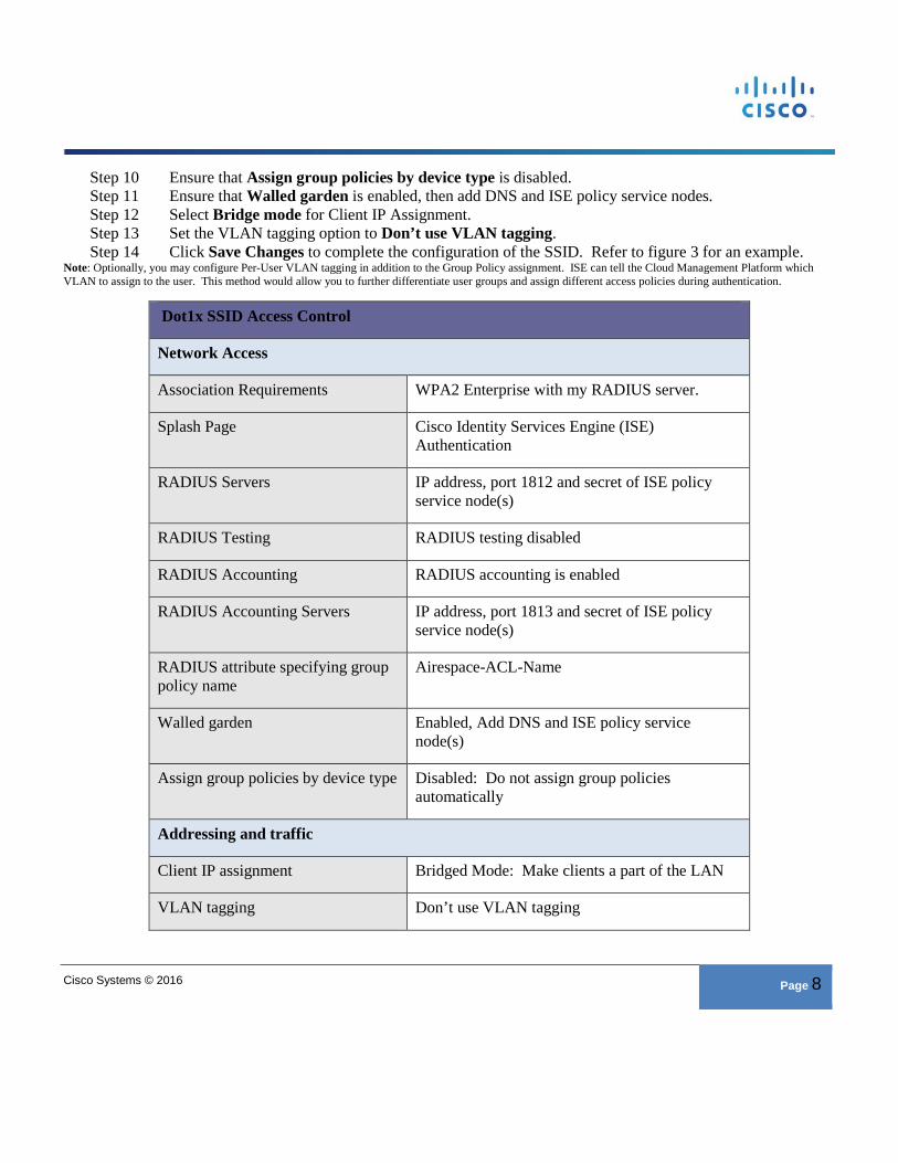
Step 10 Ensure that Assign group policies by device type is disabled. Step 11 Ensure that Walled garden is enabled, then add DNS and ISE policy service nodes. Step 12 Select Bridge mode for Client IP Assignment. Step 13 Set the VLAN tagging option to Don’t use VLAN tagging. Step 14 Click Save Changes to complete the configuration of the SSID. Refer to figure 3 for an example.
Note: Optionally, you may configure Per-User VLAN tagging in addition to the Group Policy assignment. ISE can tell the Cloud Management Platform which VLAN to assign to the user. This method would allow you to further differentiate user groups and assign different access policies during authentication.
Dot1x SSID Access Control
Network Access
Association Requirements WPA2 Enterprise with my RADIUS server.
Splash Page Cisco Identity Services Engine (ISE) Authentication
RADIUS Servers IP address, port 1812 and secret of ISE policy service node(s)
RADIUS Testing RADIUS testing disabled
RADIUS Accounting RADIUS accounting is enabled
RADIUS Accounting Servers IP address, port 1813 and secret of ISE policy service node(s)
RADIUS attribute specifying group policy name
Airespace-ACL-Name
Walled garden Enabled, Add DNS and ISE policy service node(s)
Assign group policies by device type Disabled: Do not assign group policies automatically
Addressing and traffic
Client IP assignment Bridged Mode: Make clients a part of the LAN
VLAN tagging Don’t use VLAN tagging
Cisco Systems © 2016 Page 9
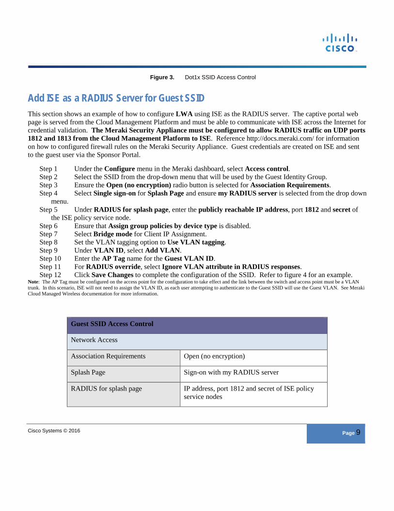
Figure 3. Dot1x SSID Access Control
Add ISE as a RADIUS Server for Guest SSID This section shows an example of how to configure LWA using ISE as the RADIUS server. The captive portal web page is served from the Cloud Management Platform and must be able to communicate with ISE across the Internet for credential validation. The Meraki Security Appliance must be configured to allow RADIUS traffic on UDP ports 1812 and 1813 from the Cloud Management Platform to ISE. Reference http://docs.meraki.com/ for information on how to configured firewall rules on the Meraki Security Appliance. Guest credentials are created on ISE and sent to the guest user via the Sponsor Portal.
Step 1 Under the Configure menu in the Meraki dashboard, select Access control. Step 2 Select the SSID from the drop-down menu that will be used by the Guest Identity Group. Step 3 Ensure the Open (no encryption) radio button is selected for Association Requirements. Step 4 Select Single sign-on for Splash Page and ensure my RADIUS server is selected from the drop down
menu. Step 5 Under RADIUS for splash page, enter the publicly reachable IP address, port 1812 and secret of
the ISE policy service node. Step 6 Ensure that Assign group policies by device type is disabled. Step 7 Select Bridge mode for Client IP Assignment. Step 8 Set the VLAN tagging option to Use VLAN tagging. Step 9 Under VLAN ID, select Add VLAN. Step 10 Enter the AP Tag name for the Guest VLAN ID. Step 11 For RADIUS override, select Ignore VLAN attribute in RADIUS responses. Step 12 Click Save Changes to complete the configuration of the SSID. Refer to figure 4 for an example.
Note: The AP Tag must be configured on the access point for the configuration to take effect and the link between the switch and access point must be a VLAN trunk. In this scenario, ISE will not need to assign the VLAN ID, as each user attempting to authenticate to the Guest SSID will use the Guest VLAN. See Meraki Cloud Managed Wireless documentation for more information.
Guest SSID Access Control
Network Access
Association Requirements Open (no encryption)
Splash Page Sign-on with my RADIUS server
RADIUS for splash page IP address, port 1812 and secret of ISE policy service nodes
Cisco Systems © 2016 Page 10
Assign group policies by device type Disabled: Do not assign group policies automatically
Addressing and traffic
Client IP assignment Bridged Mode: Make clients a part of the LAN
VLAN tagging Use VLAN tagging
VLAN ID AP Tag and VLAN ID of guest VLAN on upstream switch
RADIUS override Ignore VLAN attribute in RADIUS responses
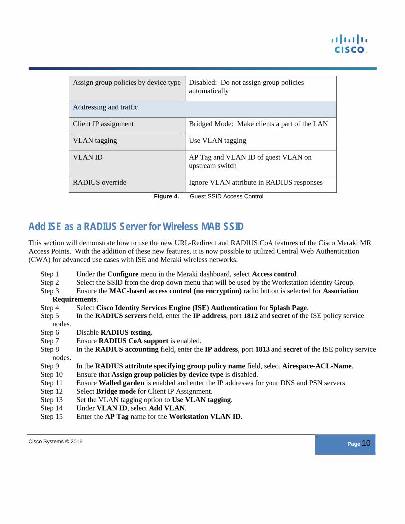
Figure 4. Guest SSID Access Control
Add ISE as a RADIUS Server for Wireless MAB SSID This section will demonstrate how to use the new URL-Redirect and RADIUS CoA features of the Cisco Meraki MR Access Points. With the addition of these new features, it is now possible to utilized Central Web Authentication (CWA) for advanced use cases with ISE and Meraki wireless networks.
Step 1 Under the Configure menu in the Meraki dashboard, select Access control. Step 2 Select the SSID from the drop down menu that will be used by the Workstation Identity Group. Step 3 Ensure the MAC-based access control (no encryption) radio button is selected for Association
Requirements. Step 4 Select Cisco Identity Services Engine (ISE) Authentication for Splash Page. Step 5 In the RADIUS servers field, enter the IP address, port 1812 and secret of the ISE policy service
nodes. Step 6 Disable RADIUS testing. Step 7 Ensure RADIUS CoA support is enabled. Step 8 In the RADIUS accounting field, enter the IP address, port 1813 and secret of the ISE policy service
nodes. Step 9 In the RADIUS attribute specifying group policy name field, select Airespace-ACL-Name. Step 10 Ensure that Assign group policies by device type is disabled. Step 11 Ensure Walled garden is enabled and enter the IP addresses for your DNS and PSN servers Step 12 Select Bridge mode for Client IP Assignment. Step 13 Set the VLAN tagging option to Use VLAN tagging. Step 14 Under VLAN ID, select Add VLAN. Step 15 Enter the AP Tag name for the Workstation VLAN ID.
Cisco Systems © 2016 Page 11
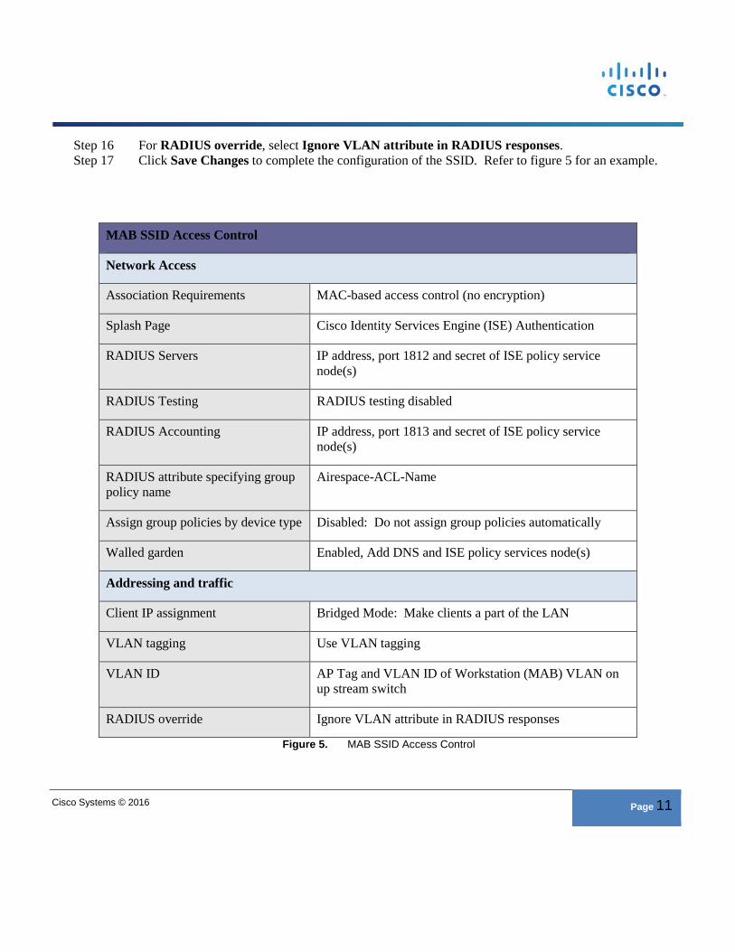
Step 16 For RADIUS override, select Ignore VLAN attribute in RADIUS responses. Step 17 Click Save Changes to complete the configuration of the SSID. Refer to figure 5 for an example.
MAB SSID Access Control
Network Access
Association Requirements MAC-based access control (no encryption)
Splash Page Cisco Identity Services Engine (ISE) Authentication
RADIUS Servers IP address, port 1812 and secret of ISE policy service node(s)
RADIUS Testing RADIUS testing disabled
RADIUS Accounting IP address, port 1813 and secret of ISE policy service node(s)
RADIUS attribute specifying group policy name
Airespace-ACL-Name
Assign group policies by device type Disabled: Do not assign group policies automatically
Walled garden Enabled, Add DNS and ISE policy services node(s)
Addressing and traffic
Client IP assignment Bridged Mode: Make clients a part of the LAN
VLAN tagging Use VLAN tagging
VLAN ID AP Tag and VLAN ID of Workstation (MAB) VLAN on up stream switch
RADIUS override Ignore VLAN attribute in RADIUS responses
Figure 5. MAB SSID Access Control
Cisco Systems © 2016 Page 12
Meraki Wired Network Configuration This section outlines the configuration steps necessary to use ISE as a RADIUS server for use with Meraki switches. Meraki switches operate in a closed mode. In contrast to Meraki wireless networks, you do not have the ability to apply Meraki Group Policy during authentication. Optionally, you may configure a guest VLAN. This is useful in the event of authentication failure or for wired guest access to the network.
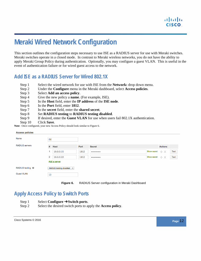
Add ISE as a RADIUS Server for Wired 802.1X Step 1 Select the wired network for use with ISE from the Network: drop down menu. Step 2 Under the Configure menu in the Meraki dashboard, select Access policies. Step 3 Select Add an access policy. Step 4 Give the new policy a name. (For example, ISE). Step 5 In the Host field, enter the IP address of the ISE node. Step 6 In the Port field, enter 1812. Step 7 In the secret field, enter the shared secret. Step 8 Set RADIUS testing to RADIUS testing disabled. Step 9 If desired, enter the Guest VLAN for use when users fail 802.1X authentication. Step 10 Click Save.
Note: Once configured, your new Access Policy should look similar to Figure 6.
Figure 6. RADIUS Server configuration in Meraki Dashboard
Apply Access Policy to Switch Ports Step 1 Select Configure ➔ Switch ports. Step 2 Select the desired switch ports to apply the Access policy.
Cisco Systems © 2016 Page 13
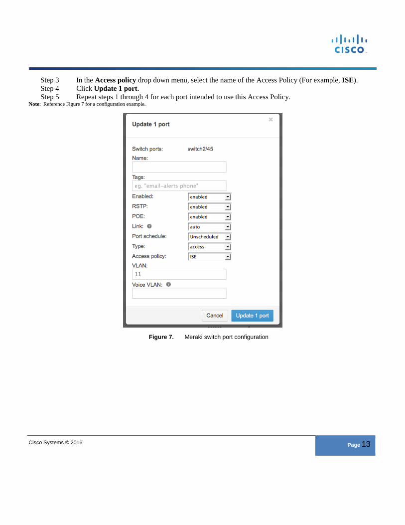
Step 3 In the Access policy drop down menu, select the name of the Access Policy (For example, ISE). Step 4 Click Update 1 port. Step 5 Repeat steps 1 through 4 for each port intended to use this Access Policy.
Note: Reference Figure 7 for a configuration example.
Figure 7. Meraki switch port configuration
Cisco Systems © 2016 Page 14
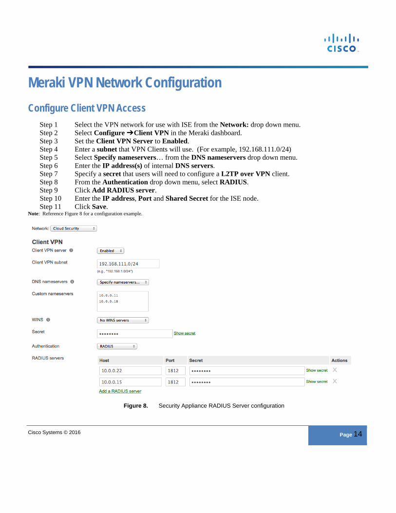
Meraki VPN Network Configuration Configure Client VPN Access
Step 1 Select the VPN network for use with ISE from the Network: drop down menu. Step 2 Select Configure ➔ Client VPN in the Meraki dashboard. Step 3 Set the Client VPN Server to Enabled. Step 4 Enter a subnet that VPN Clients will use. (For example, 192.168.111.0/24) Step 5 Select Specify nameservers… from the DNS nameservers drop down menu. Step 6 Enter the IP address(s) of internal DNS servers. Step 7 Specify a secret that users will need to configure a L2TP over VPN client. Step 8 From the Authentication drop down menu, select RADIUS. Step 9 Click Add RADIUS server. Step 10 Enter the IP address, Port and Shared Secret for the ISE node. Step 11 Click Save.
Note: Reference Figure 8 for a configuration example.
Figure 8. Security Appliance RADIUS Server configuration
Cisco Systems © 2016 Page 15
Cisco Systems © 2016 Page 16
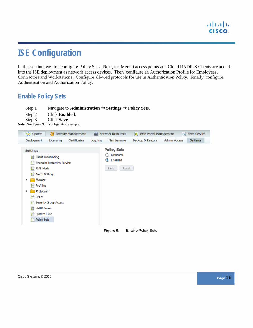
ISE Configuration In this section, we first configure Policy Sets. Next, the Meraki access points and Cloud RADIUS Clients are added into the ISE deployment as network access devices. Then, configure an Authorization Profile for Employees, Contractors and Workstations. Configure allowed protocols for use in Authentication Policy. Finally, configure Authentication and Authorization Policy.
Enable Policy Sets Step 1 Navigate to Administration ➔ Settings ➔ Policy Sets. Step 2 Click Enabled. Step 3 Click Save.
Note: See Figure 9 for configuration example.
Figure 9. Enable Policy Sets
Cisco Systems © 2016 Page 17
Add Meraki Access Point as a Network Access Devices Step 1 Navigate to Administration ➔ Network Devices. Step 2 Click Add to create a new network device. Step 3 Enter a name for the Cisco Meraki access point. Step 4 Enter the IP address of the access point. Step 5 Define the Device Type and Location of the access point.
Cisco Best Practice: Predefined Device Type and Location in the Network Device Groups menu. Putting all Meraki access points in a unique Device Type group will allow you to reference them in authentication and authorization policy later.
Step 6 Check the box for Authentication Settings and enter the shared secret. Step 7 Click Submit. Step 8 Repeat steps 1 through 7 for additional Meraki access points that will be used in the ISE deployment.
Note: You have the ability to bulk import network access devices. Simply click on “Import” and then “generate a template.” Be sure to fill out all the required fields in the CSV template prior to uploading to ISE.
Add Meraki Switch as a Network Access Device Step 1 Click Add to create a new network device. Step 2 Enter a name for the Cisco Meraki switch. Step 3 Enter the IP address of the switch. Step 4 Define the Device Type and Location of the access point. Step 5 Check the box for Authentication Settings and enter the shared secret. Step 6 Click Submit.
Add Meraki Security Appliance as a Network Access Device Step 1 Click Add to create a new network device. Step 2 Enter a name for the Cisco Meraki security appliance. Step 3 Enter the IP address for the access point. Step 4 Define the Device Type and Location of the access point. Step 5 Check the box for Authentication Settings and enter the shared secret. Step 6 Click Submit.
Note: To use Meraki LWA, you must add the Cloud Management Platform itself as a network access device (NAD). RADIUS requests from the Cloud Management Platform will come from one of four public IP addresses: 64.156.192.245, 64.156.192.68, 74.50.51.16, and 74.50.56.161. Create a NAD entry in ISE for each public IP address. Please check Meraki documentation to ensure those public addresses are still in use.
Add Meraki Cloud RADIUS Clients as Network Access Devices Step 1 Navigate to Administration ➔ Network Devices.
Cisco Systems © 2016 Page 18
Step 2 Click Add to create a new network device. Step 3 Enter a name for the Meraki access point. Step 4 Enter one of the IP addresses for the Cloud RADIUS client. Step 5 Define the Device Type and Location of the access point. Step 6 Check the box for Authentication Settings and enter the shared secret. Step 7 Click Submit. Step 8 Repeat steps 1 through 7 for the remaining three Cloud RADIUS Clients.
Authorization Profiles This procedure outlines the process necessary to tie ISE Authorization Policy to Group Policy on the Cisco Meraki access point. We will create several Authorizations Profiles for use in Authorization Policy. For Cisco Meraki networks that will not use a Group Policy, we use the prebuilt Authorization Profile PermitAccess in Authorization Policy.
Step 1 Navigate to Policy ➔Results ➔Authorization ➔ Authorization Profiles. Step 2 Click Add to create a new Authorization Profile. Step 3 Name the Authorization Profile MerakiWirelessEmployee and leave the access type set to
Access_Accept. Step 4 Under Common Tasks, Check the box for Airespace ACL Name and enter Employee. Step 5 Click Submit to save the new Authorization Profile. Step 6 Repeat steps 1 through 5 and name the profile MerakiWirelessContractor and use Contractor for
the Airespace ACL Name. Step 7 Repeat steps 1 through 5 and name the profile MerakiWirelessWorkstation and use Workstation for
the Airespace ACL Name. Step 8 Repeat steps 1 through 5 and name the profile MerakiWirelessGuest and use Guest for the
Airespace ACL Name. Step 9 Click Add to create a new Authorization Profile. Step 10 Name the Authorization Profile MerakiHotSpot. Step 11 Under Common Tasks, Check the box for Web Redirection and select HotSpot and the HotSpot
guest portal from the drop-down menus. Enter CWA as the redirect ACL. Step 12 Click Submit to save the new Authorization Profile. Step 13 Repeat steps 9 through 12, name the profile MerakiMDMEnrollment, and select MDM Redirect
and MDM Portal from the drop-down menus. Enter CWA as the redirect ACL. Step 14 Repeat steps 9 through 12, name the profile MerakiNSP, and select Native Supplicant Provisioning
and BYOD Portal from the drop-down menus. Enter CWA as the redirect ACL. Step 15 Repeat steps 9 through 12, name the profile MerakiGuestRedirect, and select Central Web Auth
and Self-registered Guest Portal from the drop-down menus. Enter CWA as the redirect ACL.
Cisco Systems © 2016 Page 19
Step 16 Repeat steps 9 through 12, name the profile MerakiPosture, and select Client Provisioning (Posture) and Client Provisioning Portal from the drop-down menus. Enter CWA as the redirect ACL.
Note: The Airespace ACL Name is the name of the group policy configured on the Meraki cloud controller (Figure 3) for use with ISE Authorization Profile. The Meraki cloud controller can be configured to look for 1 of 3 compatible RADIUS messages from Cisco ISE: Filter-ID, Airespace-ACL-Name and Reply-Message. This example uses Airespace-ACL-Name.
Allowed Protocols Step 1 Navigate to Policy ➔Results ➔Authentication ➔ Allowed Protocols. Step 2 Click Add. Step 3 Enter a name for the new allowed protocols list. (For example, Meraki) Step 4 Check the box for Allow PAP/ASCII. Step 5 Under Allow PAP/ASCII, check the box for Detect PAP as Host Lookup. Step 6 Check the box for Allow PEAP and under Inner Methods check Allow PEAP-MSCHAPv2. Step 7 Click Submit.
Note: This example uses PEAP-MSCHAPv2 as the protocol to 802.1X authentications. Be sure you understand the needs of clients on your network prior to enabling or disabling allowed protocols. Reference Figure 10 as an example configuration.
Cisco Systems © 2016 Page 20
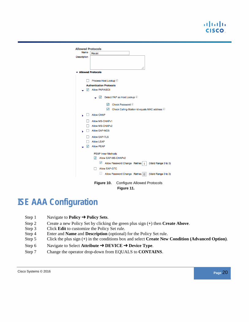
Figure 10. Configure Allowed Protocols
Figure 11.
ISE AAA Configuration Step 1 Navigate to Policy ➔ Policy Sets. Step 2 Create a new Policy Set by clicking the green plus sign (+) then Create Above. Step 3 Click Edit to customize the Policy Set rule. Step 4 Enter and Name and Description (optional) for the Policy Set rule. Step 5 Click the plus sign (+) in the conditions box and select Create New Condition (Advanced Option). Step 6 Navigate to Select Attribute ➔ DEVICE ➔ Device Type. Step 7 Change the operator drop-down from EQUALS to CONTAINS.
Cisco Systems © 2016 Page 21
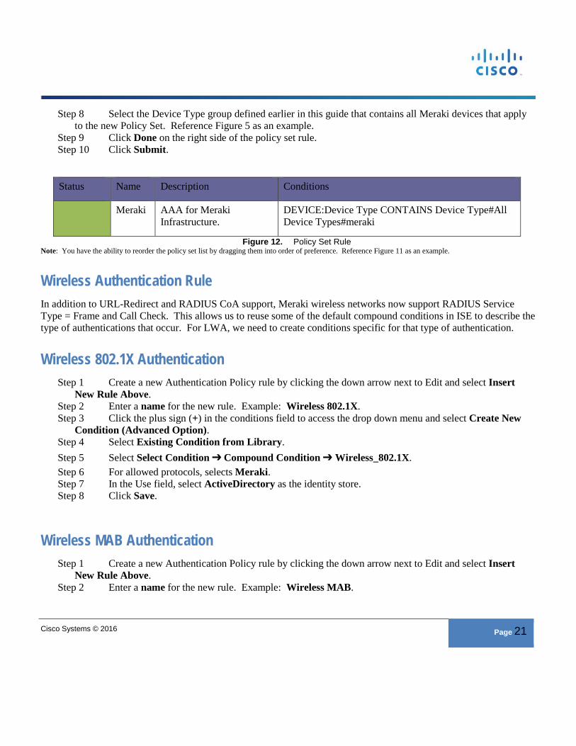
Step 8 Select the Device Type group defined earlier in this guide that contains all Meraki devices that apply to the new Policy Set. Reference Figure 5 as an example.
Step 9 Click Done on the right side of the policy set rule. Step 10 Click Submit.
Status Name Description Conditions
Meraki AAA for Meraki Infrastructure.
DEVICE:Device Type CONTAINS Device Type#All Device Types#meraki
Figure 12. Policy Set Rule Note: You have the ability to reorder the policy set list by dragging them into order of preference. Reference Figure 11 as an example.
Wireless Authentication Rule In addition to URL-Redirect and RADIUS CoA support, Meraki wireless networks now support RADIUS Service Type = Frame and Call Check. This allows us to reuse some of the default compound conditions in ISE to describe the type of authentications that occur. For LWA, we need to create conditions specific for that type of authentication.
Wireless 802.1X Authentication Step 1 Create a new Authentication Policy rule by clicking the down arrow next to Edit and select Insert
New Rule Above. Step 2 Enter a name for the new rule. Example: Wireless 802.1X. Step 3 Click the plus sign (+) in the conditions field to access the drop down menu and select Create New
Condition (Advanced Option). Step 4 Select Existing Condition from Library. Step 5 Select Select Condition ➔ Compound Condition ➔ Wireless_802.1X. Step 6 For allowed protocols, selects Meraki. Step 7 In the Use field, select ActiveDirectory as the identity store. Step 8 Click Save.
Wireless MAB Authentication Step 1 Create a new Authentication Policy rule by clicking the down arrow next to Edit and select Insert
New Rule Above. Step 2 Enter a name for the new rule. Example: Wireless MAB.
Cisco Systems © 2016 Page 22
Step 3 Click the plus sign (+) in the conditions field to access the drop down menu and select Create New Condition (Advanced Option).
Step 4 Select Existing Condition from Library. Step 5 Select Select Condition ➔ Compound Condition ➔ Wireless_MAB. Step 6 For allowed protocols, select Meraki. Step 7 In the Use field, select Internal Endpoints as the identity store. Step 8 Under Options: If user not found, select Continue. Step 9 Click Save.
Wireless Local Web Authentication Step 1 Create a new Authentication Policy rule by clicking the down arrow next to Edit and select Insert
New Rule Above. Step 2 Enter a name for the new rule. Example: Wireless LWA. Step 3 Click the plus sign (+) in the conditions field to access the drop down menu and select Create New
Condition (Advanced Option). Step 4 Select the attribute RADIUS ➔ NAS-Port-Type. Step 5 Leave the operator box set to EQUALS. Step 6 In the last drop down box, select Wireless - IEEE 802.11. Step 7 Click the down arrow next to the gear icon and select Add Attribute/Value. Step 8 Select RADIUS Service-Type. Step 9 Leave the operator box set to EQUALS. Step 10 In the last box select Login. Step 11 For allowed protocols, select Meraki. Step 12 In the “Use:” field, select Internal Users as the identity store. Step 13 Click Save.
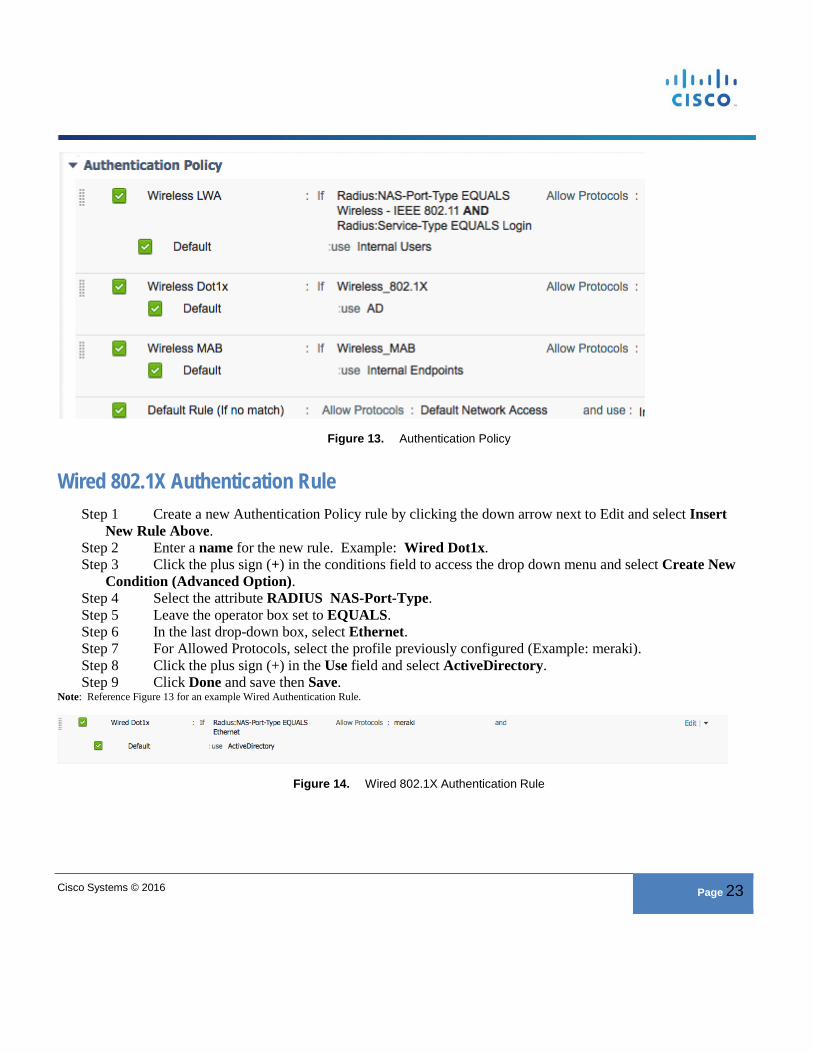
Cisco Best Practice: Once configured, your Authentication Policy will look similar to Figure 12. If these rules are used in a production environment, be sure to set the Default rule to use DenyAccess as the identity store. In addition, you can configure an Identity Source Sequence for use with authenticating Active Directory users as well as guest users via LWA. Simply change the LWA rule to use the name of the Identity Source Sequence instead of Active Directory. See the ISE Administrators Guide for more information on Identity Source Sequences.
Cisco Systems © 2016 Page 23
Figure 13. Authentication Policy
Wired 802.1X Authentication Rule Step 1 Create a new Authentication Policy rule by clicking the down arrow next to Edit and select Insert
New Rule Above. Step 2 Enter a name for the new rule. Example: Wired Dot1x. Step 3 Click the plus sign (+) in the conditions field to access the drop down menu and select Create New
Condition (Advanced Option). Step 4 Select the attribute RADIUS NAS-Port-Type. Step 5 Leave the operator box set to EQUALS. Step 6 In the last drop-down box, select Ethernet. Step 7 For Allowed Protocols, select the profile previously configured (Example: meraki). Step 8 Click the plus sign (+) in the Use field and select ActiveDirectory. Step 9 Click Done and save then Save.
Note: Reference Figure 13 for an example Wired Authentication Rule.
Figure 14. Wired 802.1X Authentication Rule
Cisco Systems © 2016 Page 24
RA VPN Authentication Rule Step 1 Create a new Authentication Policy rule by clicking the down arrow next to Edit and select Insert
New Rule Above. Step 2 Enter a name for the new rule. Example: RA VPN. Step 3 Click the plus sign (+) in the conditions field to access the drop-down menu and select Create New
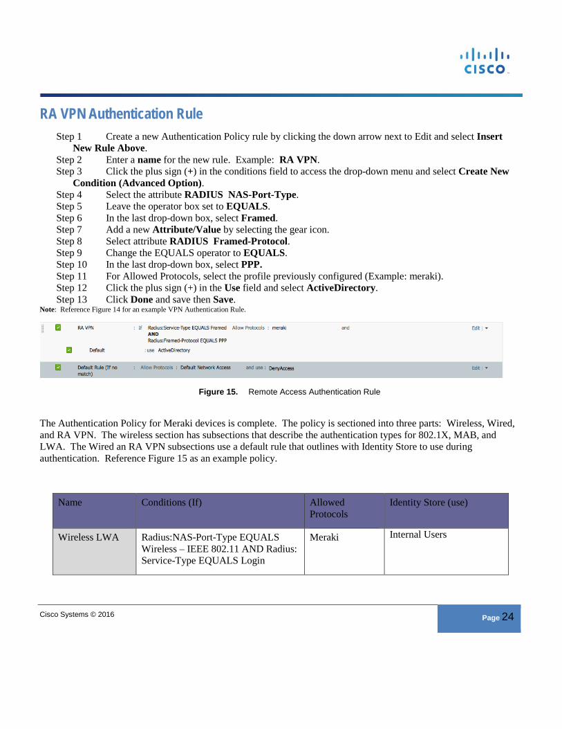
Condition (Advanced Option). Step 4 Select the attribute RADIUS NAS-Port-Type. Step 5 Leave the operator box set to EQUALS. Step 6 In the last drop-down box, select Framed. Step 7 Add a new Attribute/Value by selecting the gear icon. Step 8 Select attribute RADIUS Framed-Protocol. Step 9 Change the EQUALS operator to EQUALS. Step 10 In the last drop-down box, select PPP. Step 11 For Allowed Protocols, select the profile previously configured (Example: meraki). Step 12 Click the plus sign (+) in the Use field and select ActiveDirectory. Step 13 Click Done and save then Save.
Note: Reference Figure 14 for an example VPN Authentication Rule.
Figure 15. Remote Access Authentication Rule
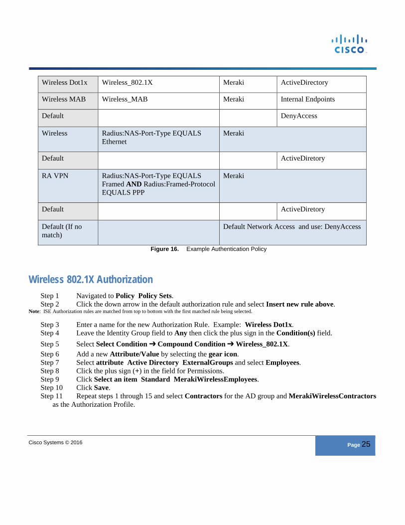
The Authentication Policy for Meraki devices is complete. The policy is sectioned into three parts: Wireless, Wired, and RA VPN. The wireless section has subsections that describe the authentication types for 802.1X, MAB, and LWA. The Wired an RA VPN subsections use a default rule that outlines with Identity Store to use during authentication. Reference Figure 15 as an example policy.
Name Conditions (If) Allowed Protocols
Identity Store (use)
Wireless LWA Radius:NAS-Port-Type EQUALS Wireless – IEEE 802.11 AND Radius: Service-Type EQUALS Login
Meraki Internal Users
Cisco Systems © 2016 Page 25
Wireless Dot1x Wireless_802.1X Meraki ActiveDirectory
Wireless MAB Wireless_MAB Meraki Internal Endpoints
Default DenyAccess
Wireless Radius:NAS-Port-Type EQUALS Ethernet
Meraki
Default ActiveDiretory
RA VPN Radius:NAS-Port-Type EQUALS Framed AND Radius:Framed-Protocol EQUALS PPP
Meraki
Default ActiveDiretory
Default (If no match)
Default Network Access and use: DenyAccess
Figure 16. Example Authentication Policy
Wireless 802.1X Authorization Step 1 Navigated to Policy Policy Sets. Step 2 Click the down arrow in the default authorization rule and select Insert new rule above.
Note: ISE Authorization rules are matched from top to bottom with the first matched rule being selected.
Step 3 Enter a name for the new Authorization Rule. Example: Wireless Dot1x. Step 4 Leave the Identity Group field to Any then click the plus sign in the Condition(s) field. Step 5 Select Select Condition ➔ Compound Condition ➔ Wireless_802.1X. Step 6 Add a new Attribute/Value by selecting the gear icon. Step 7 Select attribute Active Directory ExternalGroups and select Employees. Step 8 Click the plus sign (+) in the field for Permissions. Step 9 Click Select an item Standard MerakiWirelessEmployees. Step 10 Click Save. Step 11 Repeat steps 1 through 15 and select Contractors for the AD group and MerakiWirelessContractors
as the Authorization Profile.
Cisco Systems © 2016 Page 26
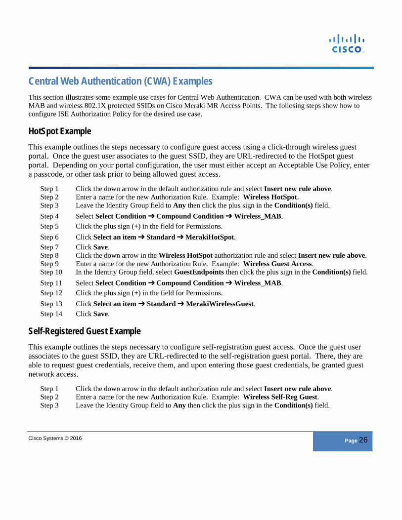
Central Web Authentication (CWA) Examples This section illustrates some example use cases for Central Web Authentication. CWA can be used with both wireless MAB and wireless 802.1X protected SSIDs on Cisco Meraki MR Access Points. The follosing steps show how to configure ISE Authorization Policy for the desired use case.
HotSpot Example This example outlines the steps necessary to configure guest access using a click-through wireless guest portal. Once the guest user associates to the guest SSID, they are URL-redirected to the HotSpot guest portal. Depending on your portal configuration, the user must either accept an Acceptable Use Policy, enter a passcode, or other task prior to being allowed guest access.
Step 1 Click the down arrow in the default authorization rule and select Insert new rule above. Step 2 Enter a name for the new Authorization Rule. Example: Wireless HotSpot. Step 3 Leave the Identity Group field to Any then click the plus sign in the Condition(s) field. Step 4 Select Select Condition ➔ Compound Condition ➔ Wireless_MAB. Step 5 Click the plus sign (+) in the field for Permissions. Step 6 Click Select an item ➔ Standard ➔ MerakiHotSpot. Step 7 Click Save. Step 8 Click the down arrow in the Wireless HotSpot authorization rule and select Insert new rule above. Step 9 Enter a name for the new Authorization Rule. Example: Wireless Guest Access. Step 10 In the Identity Group field, select GuestEndpoints then click the plus sign in the Condition(s) field. Step 11 Select Select Condition ➔ Compound Condition ➔ Wireless_MAB. Step 12 Click the plus sign (+) in the field for Permissions. Step 13 Click Select an item ➔ Standard ➔ MerakiWirelessGuest. Step 14 Click Save.
Self-Registered Guest Example This example outlines the steps necessary to configure self-registration guest access. Once the guest user associates to the guest SSID, they are URL-redirected to the self-registration guest portal. There, they are able to request guest credentials, receive them, and upon entering those guest credentials, be granted guest network access.
Step 1 Click the down arrow in the default authorization rule and select Insert new rule above. Step 2 Enter a name for the new Authorization Rule. Example: Wireless Self-Reg Guest. Step 3 Leave the Identity Group field to Any then click the plus sign in the Condition(s) field.
Cisco Systems © 2016 Page 27
Step 4 Select Select Condition ➔ Compound Condition ➔ Wireless_MAB. Step 5 Click the plus sign (+) in the field for Permissions. Step 6 Click Select an item ➔ Standard ➔ MerakiSelfRegGuest. Step 7 Click Save. Step 8 Click the down arrow in the Wireless HotSpot authorization rule and select Insert new rule above. Step 9 Enter a name for the new Authorization Rule. Example: Wireless Guest Access. Step 10 In the Identity Group field, select GuestEndpoints then click the plus sign in the Condition(s) field. Step 11 Select Select Condition ➔ Compound Condition ➔ Wireless_MAB. Step 12 Click the plus sign (+) in the field for Permissions. Step 13 Click Select an item ➔ Standard ➔ MerakiWirelessGuest. Step 14 Click Save.
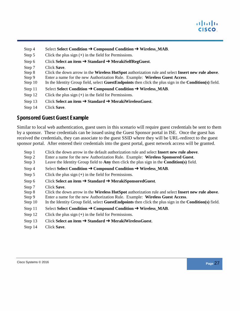
Sponsored Guest Guest Example Similar to local web authentication, guest users in this scenario will require guest credentials be sent to them by a sponsor. These credentials can be issued using the Guest Sponsor portal in ISE. Once the guest has received the credentials, they can associate to the guest SSID where they will be URL-redirect to the guest sponsor portal. After entered their credentials into the guest portal, guest network access will be granted.
Step 1 Click the down arrow in the default authorization rule and select Insert new rule above. Step 2 Enter a name for the new Authorization Rule. Example: Wireless Sponsored Guest. Step 3 Leave the Identity Group field to Any then click the plus sign in the Condition(s) field. Step 4 Select Select Condition ➔ Compound Condition ➔ Wireless_MAB. Step 5 Click the plus sign (+) in the field for Permissions. Step 6 Click Select an item ➔ Standard ➔ MerakiSponsoredGuest. Step 7 Click Save. Step 8 Click the down arrow in the Wireless HotSpot authorization rule and select Insert new rule above. Step 9 Enter a name for the new Authorization Rule. Example: Wireless Guest Access. Step 10 In the Identity Group field, select GuestEndpoints then click the plus sign in the Condition(s) field. Step 11 Select Select Condition ➔ Compound Condition ➔ Wireless_MAB. Step 12 Click the plus sign (+) in the field for Permissions. Step 13 Click Select an item ➔ Standard ➔ MerakiWirelessGuest. Step 14 Click Save.
Cisco Systems © 2016 Page 28
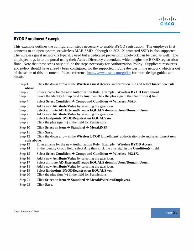
BYOD Enrollment Example This example outlines the configuration steps necessary to enable BYOD registration. The employee first connects to an open system, or wireless MAB SSID, although an 802.1X protected SSID is also supported. The wireless guest network is typically used but a dedicated provisioning network can be used as well. The employee logs in to the portal using their Active Directory credentials, which begins the BYOD registration flow. Note that these steps only outline the steps necessary for Authorization Policy. Supplicant resources and policy should have already been configured for the supported mobile devices in the network which is out of the scope of this document. Please reference http://www.cisco.com/go/ise for more design guides and details.
Step 1 Click the down arrow in the Wireless Guest Access authorization rule and select Insert new rule above.
Step 2 Enter a name for the new Authorization Rule. Example: Wireless BYOD Enrollment. Step 3 Leave the Identity Group field to Any then click the plus sign in the Condition(s) field. Step 4 Select Select Condition ➔ Compound Condition ➔ Wireless_MAB. Step 5 Add a new Attribute/Value by selecting the gear icon. Step 6 Select attribute AD:ExternalGroups EQUALS domain/Users/Domain Users. Step 7 Add a new Attribute/Value by selecting the gear icon. Step 8 Select Endpoints:BYODRegistration EQUALS no. Step 9 Click the plus sign (+) in the field for Permissions. Step 10 Click Select an item ➔ Standard ➔ MerakiNSP. Step 11 Click Save. Step 12 Click the down arrow in the Wireless BYOD Enrollment authorization rule and select Insert new
rule above. Step 13 Enter a name for the new Authorization Rule. Example: Wireless BYOD Access. Step 14 In the Identity Group field, select Any then click the plus sign in the Condition(s) field. Step 15 Select Select Condition ➔ Compound Condition ➔ Wireless_802.1X. Step 16 Add a new Attribute/Value by selecting the gear icon. Step 17 Select attribute AD:ExternalGroups EQUALS domain/Users/Domain Users. Step 18 Add a new Attribute/Value by selecting the gear icon. Step 19 Select Endpoints:BYODRegistration EQUALS yes. Step 20 Click the plus sign (+) in the field for Permissions. Step 21 Click Select an item ➔ Standard ➔ MerakiWirelessEmployees. Step 22 Click Save.
Cisco Systems © 2016 Page 29
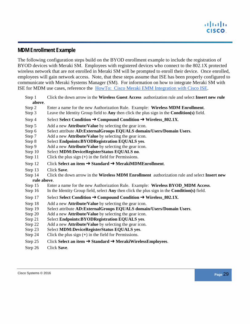
MDM Enrollment Example The following configuration steps build on the BYOD enrollment example to include the registration of BYOD devices with Meraki SM. Employees with registered devices who connect to the 802.1X protected wireless network that are not enrolled in Meraki SM will be prompted to enroll their device. Once enrolled, employees will gain network access. Note, that these steps assume that ISE has been properly configured to communicate with Meraki Systems Manager (SM). For information on how to integrate Meraki SM with ISE for MDM use cases, reference the HowTo: Cisco Meraki EMM Integration with Cisco ISE.
Step 1 Click the down arrow in the Wireless Guest Access authorization rule and select Insert new rule above.
Step 2 Enter a name for the new Authorization Rule. Example: Wireless MDM Enrollment. Step 3 Leave the Identity Group field to Any then click the plus sign in the Condition(s) field. Step 4 Select Select Condition ➔ Compound Condition ➔ Wireless_802.1X. Step 5 Add a new Attribute/Value by selecting the gear icon. Step 6 Select attribute AD:ExternalGroups EQUALS domain/Users/Domain Users. Step 7 Add a new Attribute/Value by selecting the gear icon. Step 8 Select Endpoints:BYODRegistration EQUALS yes. Step 9 Add a new Attribute/Value by selecting the gear icon. Step 10 Select MDM:DeviceRegisterStatus EQUALS no. Step 11 Click the plus sign (+) in the field for Permissions. Step 12 Click Select an item ➔ Standard ➔ MerakiMDMEnrollment. Step 13 Click Save. Step 14 Click the down arrow in the Wireless MDM Enrollment authorization rule and select Insert new
rule above. Step 15 Enter a name for the new Authorization Rule. Example: Wireless BYOD_MDM Access. Step 16 In the Identity Group field, select Any then click the plus sign in the Condition(s) field. Step 17 Select Select Condition ➔ Compound Condition ➔ Wireless_802.1X. Step 18 Add a new Attribute/Value by selecting the gear icon. Step 19 Select attribute AD:ExternalGroups EQUALS domain/Users/Domain Users. Step 20 Add a new Attribute/Value by selecting the gear icon. Step 21 Select Endpoints:BYODRegistration EQUALS yes. Step 22 Add a new Attribute/Value by selecting the gear icon. Step 23 Select MDM:DeviceRegisterStatus EQUALS yes. Step 24 Click the plus sign (+) in the field for Permissions. Step 25 Click Select an item ➔ Standard ➔ MerakiWirelessEmployees. Step 26 Click Save.
Cisco Systems © 2016 Page 30
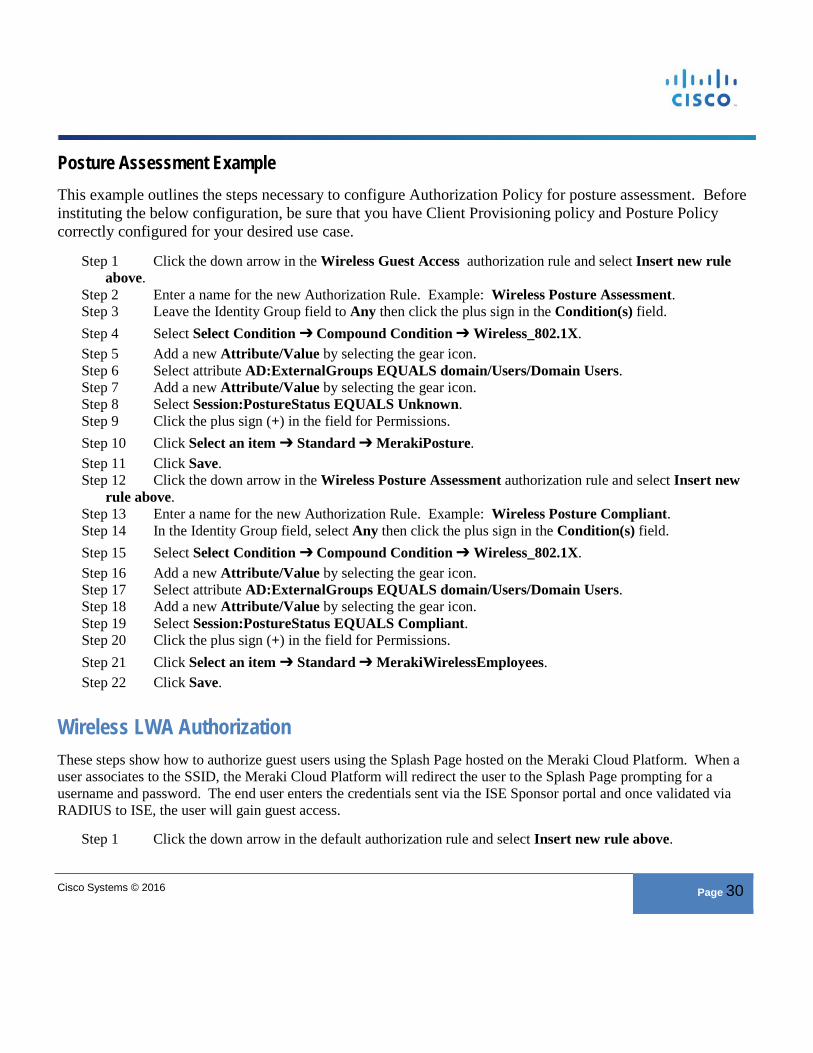
Posture Assessment Example This example outlines the steps necessary to configure Authorization Policy for posture assessment. Before instituting the below configuration, be sure that you have Client Provisioning policy and Posture Policy correctly configured for your desired use case.
Step 1 Click the down arrow in the Wireless Guest Access authorization rule and select Insert new rule above.
Step 2 Enter a name for the new Authorization Rule. Example: Wireless Posture Assessment. Step 3 Leave the Identity Group field to Any then click the plus sign in the Condition(s) field. Step 4 Select Select Condition ➔ Compound Condition ➔ Wireless_802.1X. Step 5 Add a new Attribute/Value by selecting the gear icon. Step 6 Select attribute AD:ExternalGroups EQUALS domain/Users/Domain Users. Step 7 Add a new Attribute/Value by selecting the gear icon. Step 8 Select Session:PostureStatus EQUALS Unknown. Step 9 Click the plus sign (+) in the field for Permissions. Step 10 Click Select an item ➔ Standard ➔ MerakiPosture. Step 11 Click Save. Step 12 Click the down arrow in the Wireless Posture Assessment authorization rule and select Insert new
rule above. Step 13 Enter a name for the new Authorization Rule. Example: Wireless Posture Compliant. Step 14 In the Identity Group field, select Any then click the plus sign in the Condition(s) field. Step 15 Select Select Condition ➔ Compound Condition ➔ Wireless_802.1X. Step 16 Add a new Attribute/Value by selecting the gear icon. Step 17 Select attribute AD:ExternalGroups EQUALS domain/Users/Domain Users. Step 18 Add a new Attribute/Value by selecting the gear icon. Step 19 Select Session:PostureStatus EQUALS Compliant. Step 20 Click the plus sign (+) in the field for Permissions. Step 21 Click Select an item ➔ Standard ➔ MerakiWirelessEmployees. Step 22 Click Save.
Wireless LWA Authorization These steps show how to authorize guest users using the Splash Page hosted on the Meraki Cloud Platform. When a user associates to the SSID, the Meraki Cloud Platform will redirect the user to the Splash Page prompting for a username and password. The end user enters the credentials sent via the ISE Sponsor portal and once validated via RADIUS to ISE, the user will gain guest access.
Step 1 Click the down arrow in the default authorization rule and select Insert new rule above.
Cisco Systems © 2016 Page 31
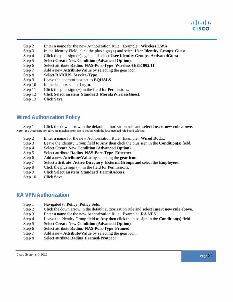
Step 2 Enter a name for the new Authorization Rule. Example: Wireless LWA. Step 3 In the Identity Field, click the plus sign (+) and select User Identity Groups Guest. Step 4 Click the plus sign (+) again and select User Identity Groups ActivatedGuest. Step 5 Select Create New Condition (Advanced Option). Step 6 Select attribute Radius NAS-Port-Type Wireless-IEEE 802.11. Step 7 Add a new Attribute/Value by selecting the gear icon. Step 8 Select RADIUS Service-Type. Step 9 Leave the operator box set to EQUALS. Step 10 In the last box select Login. Step 11 Click the plus sign (+) in the field for Permissions. Step 12 Click Select an item Standard MerakiWirelessGuest. Step 13 Click Save.
Wired Authorization Policy Step 1 Click the down arrow in the default authorization rule and select Insert new rule above.
Note: ISE Authorization rules are matched from top to bottom with the first matched rule being selected.
Step 2 Enter a name for the new Authorization Rule. Example: Wired Dot1x. Step 3 Leave the Identity Group field to Any then click the plus sign in the Condition(s) field. Step 4 Select Create New Condition (Advanced Option). Step 5 Select attribute Radius NAS-Port-Type Ethernet. Step 6 Add a new Attribute/Value by selecting the gear icon. Step 7 Select attribute Active Directory ExternalGroups and select the Employees. Step 8 Click the plus sign (+) in the field for Permissions. Step 9 Click Select an item Standard PermitAccess. Step 10 Click Save.
RA VPN Authorization Step 1 Navigated to Policy Policy Sets. Step 2 Click the down arrow in the default authorization rule and select Insert new rule above. Step 3 Enter a name for the new Authorization Rule. Example: RA VPN. Step 4 Leave the Identity Group field to Any then click the plus sign in the Condition(s) field. Step 5 Select Create New Condition (Advanced Option). Step 6 Select attribute Radius NAS-Port-Type Framed. Step 7 Add a new Attribute/Value by selecting the gear icon. Step 8 Select attribute Radius Framed-Protocol.
Cisco Systems © 2016 Page 32
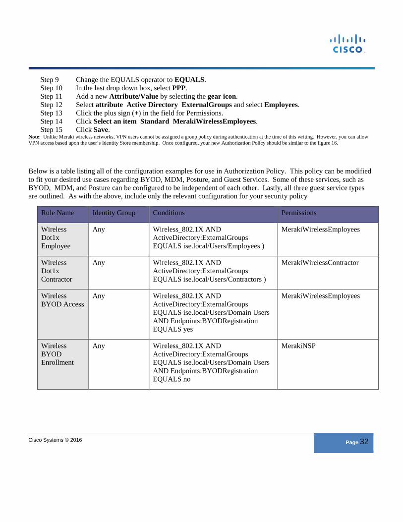
Step 9 Change the EQUALS operator to EQUALS. Step 10 In the last drop down box, select PPP. Step 11 Add a new Attribute/Value by selecting the gear icon. Step 12 Select attribute Active Directory ExternalGroups and select Employees. Step 13 Click the plus sign (+) in the field for Permissions. Step 14 Click Select an item Standard MerakiWirelessEmployees. Step 15 Click Save.
Note: Unlike Meraki wireless networks, VPN users cannot be assigned a group policy during authentication at the time of this writing. However, you can allow VPN access based upon the user’s Identity Store membership. Once configured, your new Authorization Policy should be similar to the figure 16.
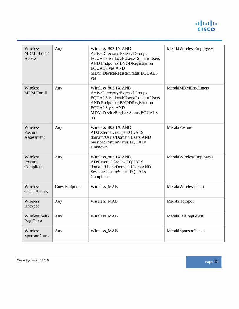
Below is a table listing all of the configuration examples for use in Authorization Policy. This policy can be modified to fit your desired use cases regarding BYOD, MDM, Posture, and Guest Services. Some of these services, such as BYOD, MDM, and Posture can be configured to be independent of each other. Lastly, all three guest service types are outlined. As with the above, include only the relevant configuration for your security policy
Rule Name Identity Group Conditions Permissions
Wireless Dot1x Employee
Any Wireless_802.1X AND ActiveDirectory:ExternalGroups EQUALS ise.local/Users/Employees )
MerakiWirelessEmployees
Wireless Dot1x Contractor
Any Wireless_802.1X AND ActiveDirectory:ExternalGroups EQUALS ise.local/Users/Contractors )
MerakiWirelessContractor
Wireless BYOD Access
Any Wireless_802.1X AND ActiveDirectory:ExternalGroups EQUALS ise.local/Users/Domain Users AND Endpoints:BYODRegistration EQUALS yes
MerakiWirelessEmployees
Wireless BYOD Enrollment
Any Wireless_802.1X AND ActiveDirectory:ExternalGroups EQUALS ise.local/Users/Domain Users AND Endpoints:BYODRegistration EQUALS no
MerakiNSP
Cisco Systems © 2016 Page 33
Wireless MDM_BYOD Access
Any Wireless_802.1X AND ActiveDirectory:ExternalGroups EQUALS ise.local/Users/Domain Users AND Endpoints:BYODRegistration EQUALS yes AND MDM:DeviceRegisterStatus EQUALS yes
MearkiWirelessEmployees
Wireless MDM Enroll
Any Wireless_802.1X AND ActiveDirectory:ExternalGroups EQUALS ise.local/Users/Domain Users AND Endpoints:BYODRegistration EQUALS yes AND MDM:DeviceRegisterStatus EQUALS no
MerakiMDMEnrollment
Wireless Posture Assessment
Any Wireless_802.1X AND AD:ExternalGroups EQUALS domain/Users/Domain Users AND Session:PostureStatus EQUALs Unknown
MerakiPosture
Wireless Posture Compliant
Any Wireless_802.1X AND AD:ExternalGroups EQUALS domain/Users/Domain Users AND Session:PostureStatus EQUALs Compliant
MerakiWirelessEmployess
Wireless Guest Access
GuestEndpoints Wireless_MAB MerakiWirelessGuest
Wireless HotSpot
Any Wireless_MAB MerakiHotSpot
Wireless Self-Reg Guest
Any Wireless_MAB MerakiSelfRegGuest
Wireless Sponsor Guest
Any Wireless_MAB MerakiSponsorGuest
Cisco Systems © 2016 Page 34
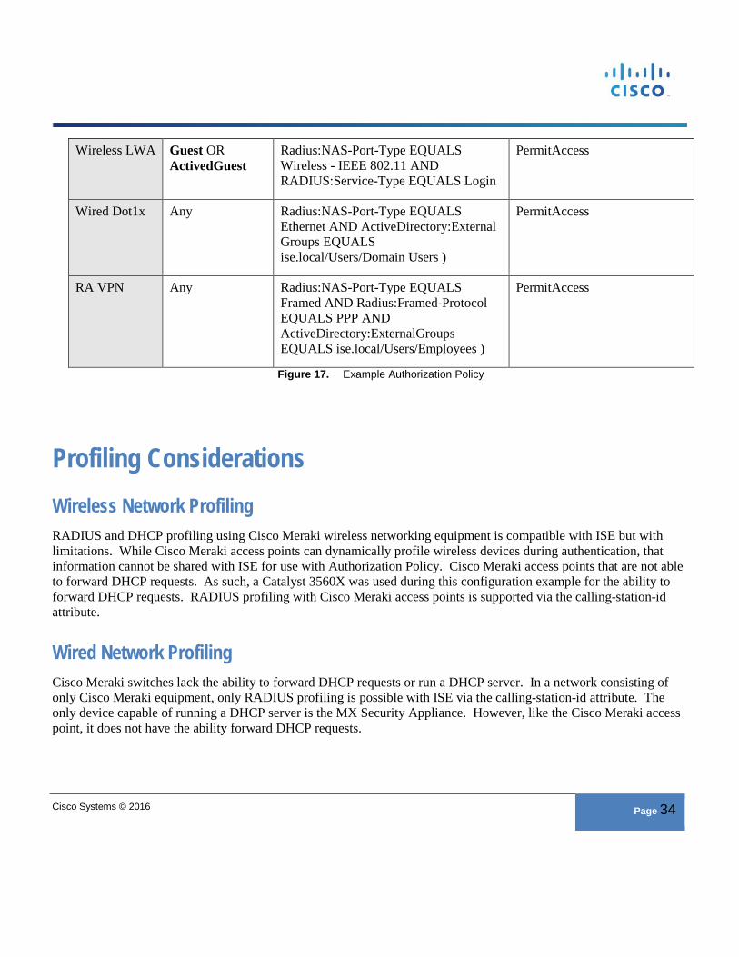
Wireless LWA Guest OR ActivedGuest
Radius:NAS-Port-Type EQUALS Wireless - IEEE 802.11 AND RADIUS:Service-Type EQUALS Login
PermitAccess
Wired Dot1x Any Radius:NAS-Port-Type EQUALS Ethernet AND ActiveDirectory:ExternalGroups EQUALS ise.local/Users/Domain Users )
PermitAccess
RA VPN Any Radius:NAS-Port-Type EQUALS Framed AND Radius:Framed-Protocol EQUALS PPP AND ActiveDirectory:ExternalGroups EQUALS ise.local/Users/Employees )
PermitAccess
Figure 17. Example Authorization Policy
Profiling Considerations Wireless Network Profiling RADIUS and DHCP profiling using Cisco Meraki wireless networking equipment is compatible with ISE but with limitations. While Cisco Meraki access points can dynamically profile wireless devices during authentication, that information cannot be shared with ISE for use with Authorization Policy. Cisco Meraki access points that are not able to forward DHCP requests. As such, a Catalyst 3560X was used during this configuration example for the ability to forward DHCP requests. RADIUS profiling with Cisco Meraki access points is supported via the calling-station-id attribute.
Wired Network Profiling Cisco Meraki switches lack the ability to forward DHCP requests or run a DHCP server. In a network consisting of only Cisco Meraki equipment, only RADIUS profiling is possible with ISE via the calling-station-id attribute. The only device capable of running a DHCP server is the MX Security Appliance. However, like the Cisco Meraki access point, it does not have the ability forward DHCP requests.

Cisco Systems © 2016 Page 35