Embed Size (px)
Citation preview
Technical Manual
V4.0.1
02 February 2007
Allied Vision Technologies GmbHTaschenweg 2aD-07646 Stadtroda / Germany
AVT Guppy
GUPPY Technical Manual V4.0.1
2
Legal noticeFor customers in the U.S.A.This equipment has been tested and found to comply with the limits for a Class B digital device, pursuant to Part 15 of the FCC Rules. These limits are designed to provide reasonable protection against harmful interference when the equipment is operated in a residential envi-ronment. This equipment generates, uses, and can radiate radio frequency energy and, if not installed and used in accordance with the instruction manual, may cause harmful interference to radio communications. However there is no guarantee that interferences will not occur in a particular installation. If the equipment does cause harmful interference to radio or televi-sion reception, the user is encouraged to try to correct the interference by one or more of the following measures:
• Reorient or relocate the receiving antenna.• Increase the distance between the equipment and the receiver.• Use a different line outlet for the receiver.• Consult a radio or TV technician for help.
You are cautioned that any changes or modifications not expressly approved in this manual could void your authority to operate this equipment. The shielded interface cable recom-mended in this manual must be used with this equipment in order to comply with the limits for a computing device pursuant to Subpart B of Part 15 of FCC Rules.
For customers in CanadaThis apparatus complies with the Class B limits for radio noise emissions set out in the Radio Interference Regulations.
Pour utilisateurs au CanadaCet appareil est conforme aux normes classe B pour bruits radioélectriques, spécifiées dans le Règlement sur le brouillage radioélectrique.
Life support applicationsThese products are not designed for use in life support appliances, devices, or systems where malfunction of these products can reasonably be expected to result in personal injury. Allied customers using or selling these products for use in such applications do so at their own risk and agree to fully indemnify Allied for any damages resulting from such improper use or sale.
TrademarksUnless stated otherwise, all trademarks appearing in this document of Allied Vision Technologies are brands protected by law.
WarrantyThe information provided by Allied Vision Technologies is supplied without any guarantees or warranty whatsoever, be it specific or implicit. Also excluded are all implicit warranties con-cerning the negotiability, the suitability for specific applications or the non-breaking of laws and patents. Even if we assume that the information supplied to us is accurate, errors and inaccuracy may still occur.
CopyrightAll texts, pictures and graphics are protected by copyright and other laws protecting intellec-tual property. It is not permitted to copy or modify them for trade use or transfer, nor may they be used on web sites.
Allied Vision Technologies GmbH 02/2007All rights reserved.Managing Director: Mr. Frank GrubeTax ID: DE 184383113
Support:
Taschenweg 2AD-07646 Stadtroda, GermanyTel.: +49 (0)36428 6770Fax: +49 (0)36428 677-28e-mail: [email protected]
GUPPY Technical Manual V4.0.1
3
Contents
Introduction ............................................................................................................ 8Document history .......................................................................................................... 8Conventions used in this manual...................................................................................... 9
Styles ...................................................................................................................... 9Symbols ................................................................................................................... 9
Before operation .......................................................................................................... 10
Declarations of conformity ...........................................................................11
Safety instructions ............................................................................................13Reference documents applicable in the United States......................................................... 13Reference documents applicable in Europe ....................................................................... 13Reference documents applicable in Japan......................................................................... 13Safety instructions........................................................................................................ 14Safety instructions for board level cameras....................................................................... 15Environmental conditions .............................................................................................. 17
Guppy types and highlights ..........................................................................18
System components .........................................................................................21Old CS-/C-Mounting ...................................................................................................... 21New CS-/C-Mounting ..................................................................................................... 22Guppy board level cameras ............................................................................................. 23IR cut filter ................................................................................................................. 24Camera lenses .............................................................................................................. 25
Specifications .......................................................................................................26Guppy F-033B .............................................................................................................. 26Guppy F-033C............................................................................................................... 28Guppy F-033B BL (board level) ....................................................................................... 30Guppy F-033C BL (board level)........................................................................................ 32Guppy F-036B .............................................................................................................. 34Guppy F-036C............................................................................................................... 36Guppy F-046B .............................................................................................................. 38Guppy F-046C............................................................................................................... 40Guppy F-080B .............................................................................................................. 42Guppy F-080C............................................................................................................... 44Guppy F-080B BL (board level) ....................................................................................... 46Guppy F-080C BL (board level)........................................................................................ 48Spectral sensitivity ....................................................................................................... 50
Camera dimensions ..........................................................................................56
GUPPY Technical Manual V4.0.1
4
Guppy standard housing (old CS-/C-Mounting) .................................................................. 56Guppy standard housing (new CS-/C-Mounting)................................................................. 57Guppy board level: dimensions ....................................................................................... 58Guppy board level: CS-Mount .......................................................................................... 59Guppy board level: C-Mount............................................................................................ 60Guppy board level: M12-Mount ....................................................................................... 61Tripod adapter ............................................................................................................. 62Cross section: C-Mount (old CS-/C-Mounting) .................................................................... 63Cross section: C-Mount (new CS-/C-Mounting)................................................................... 64Cross section: CS-Mount (old CS-/C-Mounting) .................................................................. 65Cross section: CS-Mount (new CS-/C-Mounting) ................................................................. 66
Description of the data path........................................................................67Block diagrams of the cameras ....................................................................................... 67
Black and white cameras (CCD and CMOS) .................................................................... 67Color cameras (CCD and CMOS) ................................................................................... 68
Sensor ........................................................................................................................ 69Horizontal and vertical mirror function(only Guppy F-036) ....................................................................................................... 70White balance .............................................................................................................. 71
One-push automatic white balance ............................................................................. 74Automatic white balance ........................................................................................... 75
Manual gain................................................................................................................. 77Auto gain .................................................................................................................... 77Setting the brightness (black level or offset) .................................................................... 80Auto shutter ................................................................................................................ 81Look-up table (LUT) and gamma function......................................................................... 84
Loading a LUT into the camera ................................................................................... 85Binning (b/w models) ................................................................................................... 87
2 x and 4 x binning .................................................................................................. 872 x vertical binning and 4 x vertical binning ................................................................ 882 x horizontal binning and 4 x horizontal binning......................................................... 892 x full binning and 4 x full binning............................................................................ 90
HDR (high dynamic range) (GUPPY F-036 only) ................................................................. 91Advanced registers for high dynamic range mode (HDR) (GUPPY F-036 only) ..................... 91
BAYER pattern (raw data output) .................................................................................... 92Serial interface............................................................................................................. 93
Camera interfaces .............................................................................................98IEEE 1394 port pin assignment ....................................................................................... 98
Board level camera: IEEE 1394 port pin assignment..................................................... 100Camera I/O pin assignment .......................................................................................... 101
Board level camera: I/O pin assignment..................................................................... 102Status LEDs................................................................................................................ 103
On LED (green) ...................................................................................................... 103Status LED............................................................................................................. 103
Operating the camera.................................................................................................. 105
GUPPY Technical Manual V4.0.1
5
Control and video data signals...................................................................................... 105Input ................................................................................................................... 106
Trigger ............................................................................................................. 106Input modes ..................................................................................................... 108Trigger delay ..................................................................................................... 108
Outputs ................................................................................................................ 111IO_OUTP_CTRL 1-3 ............................................................................................. 113Output modes.................................................................................................... 114
Board level cameras: inputs and outputs.................................................................... 116Board level cameras: pulse-width modulation ............................................................. 117
PWM: minimal and maximal periods and frequencies ............................................... 118PWM: Examples in practice .................................................................................. 118
Pixel data.................................................................................................................. 120
Controlling image capture ..........................................................................123Global shutter ............................................................................................................ 123Pipelined global shutter............................................................................................... 123Trigger modi .............................................................................................................. 124
Trigger delay ......................................................................................................... 127Trigger delay advanced register............................................................................ 129
Exposure time (shutter) and offset ................................................................................ 130Exposure time of CMOS sensor (GUPPY F-036) ............................................................. 130
Example GUPPY F-036 ......................................................................................... 130Camera offsets ....................................................................................................... 130
Example GUPPY F-033 ......................................................................................... 131Extended shutter.................................................................................................... 131
One-Shot................................................................................................................... 132One-shot command on the bus to start of exposure ..................................................... 133End of exposure to first packet on the bus ................................................................. 133
Multi-shot ................................................................................................................. 135ISO_Enable / Free-Run ................................................................................................ 135Asynchronous broadcast .............................................................................................. 135Jitter at start of exposure ............................................................................................ 136User profiles .............................................................................................................. 137
Video formats, modes and bandwidth .................................................138GUPPY F-025B / GUPPY F-025C ..................................................................................... 138GUPPY F-029B / GUPPY F-029C ..................................................................................... 138GUPPY F-033B/ GUPPY F-033Cand board level versions F-033B BL/F-033C BL ................................................................ 139GUPPY F-036B/ GUPPY F-036C ...................................................................................... 140GUPPY F-046B / GUPPY F-046C ..................................................................................... 141GUPPY F-080B / GUPPY F-080Cand board level versions F-080B BL/F-080C BL ................................................................ 142Area of interest (AOI) ................................................................................................. 143
Autofunction AOI ................................................................................................... 145Frame rates................................................................................................................ 146
GUPPY Technical Manual V4.0.1
6
GUPPY F-025 ......................................................................................................... 146GUPPY F-029 ......................................................................................................... 146GUPPY F-033 and board level versions ....................................................................... 147GUPPY F-036 ......................................................................................................... 148GUPPY F-046 ......................................................................................................... 149GUPPY F-080 and board level versions ....................................................................... 151
How does bandwidth affect the frame rate? ...................................153Test images ............................................................................................................... 154
Loading test images ............................................................................................... 154Test images b/w cameras......................................................................................... 154Test images for color cameras .................................................................................. 156
Test image 1 (Mono8 mode) ................................................................................ 156
Configuration of the camera......................................................................157Camera_Status_Register............................................................................................... 157
Example................................................................................................................ 158Sample program ..................................................................................................... 159
Configuration ROM...................................................................................................... 160Implemented registers................................................................................................. 163
Camera initialize register......................................................................................... 163Inquiry register for video format............................................................................... 163Inquiry register for video mode ................................................................................ 164Inquiry register for video frame rate and base address ................................................. 165Inquiry register for basic function............................................................................. 174Inquiry register for feature presence ......................................................................... 175Inquiry register for feature elements ......................................................................... 177Inquiry register for absolute value CSR offset address .................................................. 180Status and control register for feature....................................................................... 181Feature control error status register .......................................................................... 182Video mode control and status registers for Format_7.................................................. 182
Quadlet offset Format_7 Mode_0 .......................................................................... 182Quadlet offset Format_7 Mode_1 .......................................................................... 182Format_7 control and status register (CSR) ............................................................ 182
Advanced features ...................................................................................................... 184Version information inquiry ..................................................................................... 187Advanced feature inquiry......................................................................................... 189Camera status ........................................................................................................ 191Maximum resolution ............................................................................................... 192Time base ............................................................................................................. 192Extended shutter.................................................................................................... 194Test images ........................................................................................................... 195Look-up tables (LUT) .............................................................................................. 196Input/output pin control......................................................................................... 198Delayed integration enable ...................................................................................... 198Auto shutter control ............................................................................................... 199Auto gain control ................................................................................................... 200Autofunction AOI ................................................................................................... 201
GUPPY Technical Manual V4.0.1
7
Trigger delay ......................................................................................................... 203Mirror image (only Guppy F-036) .............................................................................. 204Pulse-width modulation (board level cameras only) ..................................................... 204Soft Reset ............................................................................................................. 205User profiles .......................................................................................................... 206
Error codes ....................................................................................................... 207Reset of error codes ........................................................................................... 207Stored settings .................................................................................................. 208
GPDATA_BUFFER..................................................................................................... 209
Firmware update...............................................................................................210
Glossary .................................................................................................................211
Index.........................................................................................................................232
Introduction
GUPPY Technical Manual V4.0.1
8
Introduction
Document history
Version Date Remarks
V2.0.0 06.04.2006 New Manual - RELEASE status
V2.0.1 28.06.2006 RoHS conformity; minor corrections
PRE_V3.0.0 30.10.2006 Minor corrections
Input characteristics: Added description to input voltage (Table 38: Input characteristics on page 106)
Added Guppy F-036B/C
Correction in Chapter Multi-shot on page 135
New CAD drawing in Figure 18: Camera dimensions (new CS-/C-Mounting) on page 57.
New CAD drawing in Figure 25: Guppy C-Mount dimensions (new CS-/C-Mounting) on page 64.
New CAD drawing in Figure 27: Guppy CS-Mount dimensions (new CS-/C-Mounting) on page 66.
New CS-Mount and C-Mount adapter in Chapter Guppy types and highlights on page 18.
Added Guppy F-33B/C BL (board level version)
Changed camera status register (Table 94: Camera status regis-ter on page 191)
PRE_V4.0.0 26.01.2007 Minor corrections
Added Guppy F-080B/C BL (board level version)
Added new features Guppy-F036B/C
V4.0.1 02.02.2007 Minor corrections
Table 1: Document history
Introduction
GUPPY Technical Manual V4.0.1
9
Conventions used in this manual
To give this manual an easily understood layout and to emphasize important information, the following typographical styles and symbols are used:
Styles
Symbols
Style Function Example
Bold Programs, inputs or highlighting important things
bold
Courier Code listings etc. Input
Upper case Register REGISTER
Italics Modes, fields Mode
Parentheses and/or blue Links (Link)
Table 2: Styles
Note This symbol highlights important information.
Caution This symbol highlights important instructions. You have to follow these instructions to avoid malfunctions.
Caution-ESD This symbol highlights important ESD instructions. Only qualified personnel is allowed to install and operate compo-nents marked with this symbol.
www This symbol highlights URLs for further information. The URL itself is shown in blue.
Example:
http://www.alliedvisiontec.com

Introduction
GUPPY Technical Manual V4.0.1
10
Before operation
We place the highest demands for quality on our cameras. This Technical Manual is the guide to the installation and setting up of the camera for oper-ation. You will also find the specifications and interfaces here.
Note Please read through this manual carefully before operating the camera.
Declarations of conformity
GUPPY Technical Manual V4.0.1
11
Declarations of conformity
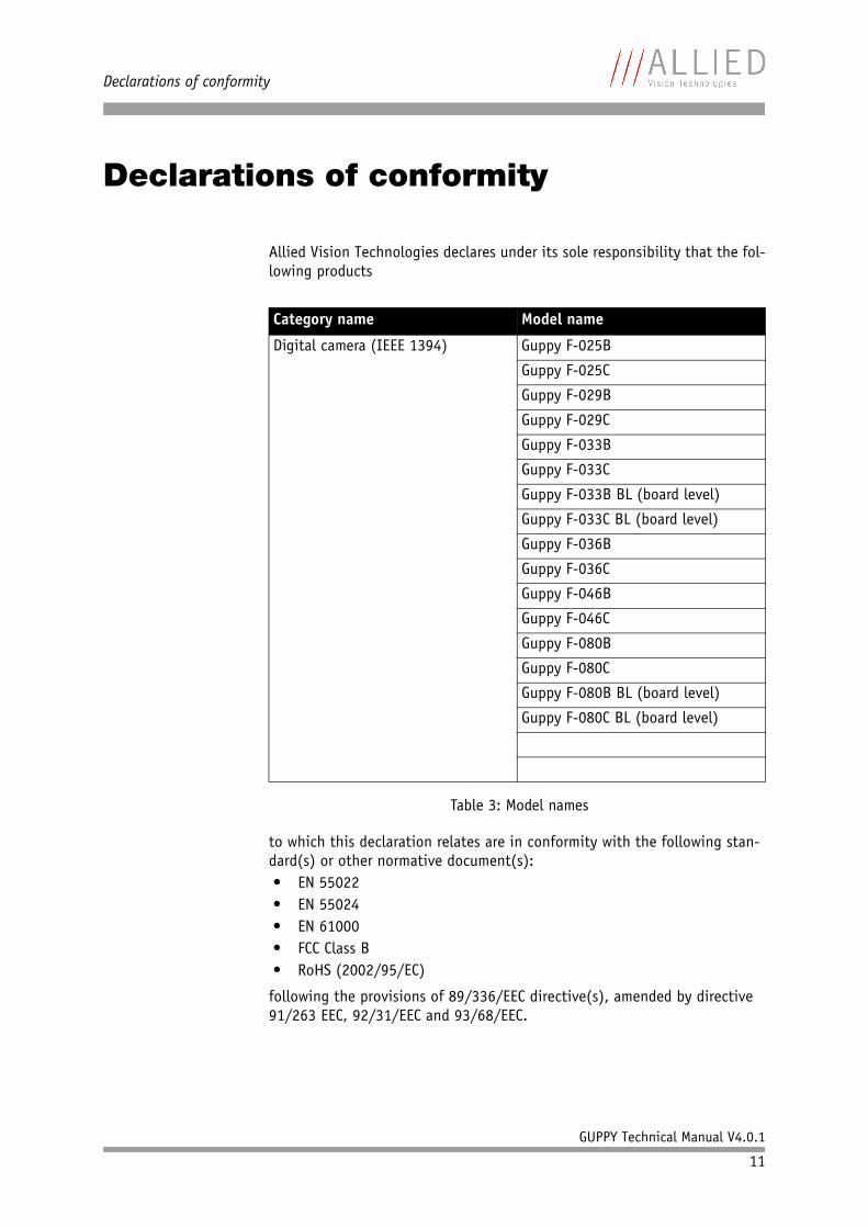
Allied Vision Technologies declares under its sole responsibility that the fol-lowing products
to which this declaration relates are in conformity with the following stan-dard(s) or other normative document(s):• EN 55022• EN 55024• EN 61000• FCC Class B• RoHS (2002/95/EC)
following the provisions of 89/336/EEC directive(s), amended by directive 91/263 EEC, 92/31/EEC and 93/68/EEC.
Category name Model name
Digital camera (IEEE 1394) Guppy F-025B
Guppy F-025C
Guppy F-029B
Guppy F-029C
Guppy F-033B
Guppy F-033C
Guppy F-033B BL (board level)
Guppy F-033C BL (board level)
Guppy F-036B
Guppy F-036C
Guppy F-046B
Guppy F-046C
Guppy F-080B
Guppy F-080C
Guppy F-080B BL (board level)
Guppy F-080C BL (board level)
Table 3: Model names

Declarations of conformity
GUPPY Technical Manual V4.0.1
12
Note Customer samples may not comply with above regulations.
Safety instructions
GUPPY Technical Manual V4.0.1
13
Safety instructions
Reference documents applicable in the United States
The reference documents include• Information Processing and Business Equipment, UL 478• National Electric Code, ANSI/NFPA 70• Standard for the Protection of Electronic Computer/Data-Processing
Equipment, ANSI/NFPA 75
Reference documents applicable in Europe
The reference documents include materials to ensure European Union CE marking as follows:• Telecommunications Terminal Equipment (91/263/EEC)• EMC Directive (89/339/EEC)• CE Marking Directive (93/68/EEC)• LOW Voltage Directive (73/23/EEC) as amended by the CE Marking
Reference documents applicable in Japan
The reference documents include:• Electronic Equipment Technology Criteria by the Ministry of Trading and
Industry (Similar to NFPA 70)
Note • There are no switches or parts inside the camera that require adjustment. The guarantee becomes void upon opening the camera casing.
• If the product is disassembled, reworked or repaired by other than a recommended service person, AVT or its suppliers will take no responsibility for the subsequent performance or quality of the camera.
• The camera does NOT generate dangerous voltages internally. However, because the IEEE 1394a standard permits cable power distribution at voltages higher than 24 V, various international safety standards apply.
Safety instructions
GUPPY Technical Manual V4.0.1
14
• Wired Electric Communication Detailed Law 17 by the Ministry of Posts and Telecom Law for Electric Equipment
• Dentori law issued by the Ministry of Trading and Industry• Fire law issued by the Ministry of Construction
Safety instructions
Caution • Make sure NOT to touch the shield of the camera cable connected to a computer and the ground terminal of the lines at the same time.
• Use only DC power supplies with insulated cases. These are identified by having only TWO power connectors.
• Although IEEE 1394a is functionally plug and play, the physical ports may be damaged by excessive ESD (elec-trostatic discharge), when connected under powered conditions. It is good practice to bring the metal part, which is the shield of the IEEE 1394 cable, in contact with the housing of the camera (before plugging it into the camera) and, at the other end, in contact with metal parts of the computer, before plugging it into the port of the computer. This ensures that excessive charge can flow safely to ground.
• If you feel uncomfortable with the previous advice, or if you have no knowledge about the connectivity of an installation, we strongly recommend powering down all systems before connecting or disconnecting a camera.
Safety instructions
GUPPY Technical Manual V4.0.1
15
Safety instructions for board level cameras
Note Read the Guppy Technical Manual and this safety instruc-tions before use.
Abuse or misapplication of the camera may result in lim-ited warranty or cancelation of warranty.
Caution-ESD Board level cameras: ESD warnings
• Only qualified personnel is allowed to install and oper-ate the Board level cameras.
• Board level camerass are delivered without housing. Handle the sensor board and main board with care. Do not bend the boards. Do not touch the components or contacts on a board. Hold a board by its edges.
• Sensor board and main board are sensitive to electro-static discharge. To avoid possible damage, handle all static-sensitive boards and components in a static-safe work area. Follow the procedures below.
• ESD (electrostatic discharge): Static electricity can damage the sensor board or the main board of your Board level cameras. To prevent static damage, dis-charge static electricity from your body before you touch any of your Board level cameras’s electronic com-ponents, such as sensor board or main board. To do so, use a static-safe workarea with static-dissipative mat and wear a static-dissipative wrist strap. Do not hold any components of your Board level cameras against your clothing. Even if you are wearing a wrist strap, your body is grounded but your clothes are not.
• Do not remove the sensor board and main board from its anti-static packaging unless your body is grounded.
• ESD shielding: To protect the boards from radiation of other modules or devices use a special ESD protective housing.
Safety instructions
GUPPY Technical Manual V4.0.1
16
Caution Board level cameras: General Warnings
• Be sure that all power to your board level cameras is switched off, before mounting the sensor board or mak-ing connections to the camera.
• Do not connect or disconnect any cables during an elec-trical storm.
• Do not use your board level cameras during an electrical storm.
• To help avoid possible damage to the sensor board or main board, wait 5 seconds after power is switched off, before connecting or disconnecting any cable to the board level cameras.
• Ensure that nothing rests on the cables of your board level cameras.
• Keep your board level cameras away from radiators and heat sources.
• Do not spill food or liquids on your board level cameras.
Caution Board level cameras: Loading
• Avoid any mechanical forces to the board level cameras, the boards and its components, especially torsional, tensile and compressive forces. Any of these forces may result in damage of the board level cameras, the boards and its components.
• To avoid damages of the boards, provide cables with an external pull relief so that no force is applied to the connectors itself.
Caution Board level cameras: Dirty environments
• Always use clean boards.• To protect the boards from dirt like dust, liquids or
swarf always use the board level cameras only in clean room environment or use a protective housing.
Safety instructions
GUPPY Technical Manual V4.0.1
17
Environmental conditions
Housing temperature (when camera in use): + 5 °C ... + 50 °C
Ambient temperature during storage: - 10 °C ... + 60 °C
Relative humidity: 20 % … 80 % without condensation
Protection (for cased models): IP 30
Protection (for board level): IP 00
Guppy types and highlights
GUPPY Technical Manual V4.0.1
18
Guppy types and highlights
With Guppy cameras, entry into the world of digital image processing is sim-pler and more cost-effective than ever before.
With the new GUPPY, Allied Vision Technologies presents a whole series of attractive digital camera entry-level models of the FireWire™ type.
These products offer an unequalled price-performance relationship and make the decision to switch from using analogue to digital technology easier than ever before.
The AVT Guppy family consists of six very compact IEEE 1394 C-Mount cam-eras, which are equipped with highly sensitive high-quality sensors (CCD, CMOS).
Each of these cameras is available in black/white and color versions.
A large selection of different sensor sizes (type 1/2, type 1/3) and resolu-tions (VGA, SVGA, XGA) ensures the suitability of the cameras for all applica-tions.
The Guppy family consists of the following models:
Operating in 8-bit mode (CCD b/w only), the cameras ensure very high quality images under almost all circumstances. The GUPPY is equipped with an asyn-chronous trigger shutter as well as true partial scan, and integrates numerous useful and intelligent smart features for image processing.
GUPPY type Sensor Picture size Frame rates
GUPPY F-025B/C Type 1/3 SONY ICX404AL/AKInterlaced EIA CCD imager
(NTSC) 508 (h) x 492 (v) up to 30 fps
(60 fields per second)
GUPPY F-029B/C Type 1/3 SONY ICX405AL/AKInterlaced CCIR CCD imager
(PAL) 500 (h) x 582 (v) up to 25 fps
(50 fields per second)
GUPPY F-033B/C and board level version
Type 1/3 Sony ICX424AL/AQProgressive Scan CCD imager
(VGA) 656 (h) x 494 (v) up to 60 fps
GUPPY F-036B/C Type 1/3 Micron Imaging MT9V022Global Shutter CMOS imager
(WideVGA) 752 (h) x 480 (v) up to 64 fps
GUPPY F-046B/C Type 1/2 Sony ICX415AL/AQProgressive Scan CCD imager
(SVGA) 780 (h) x 582 (v) up to 49 fps
GUPPY F-080B/C and board level version
Type 1/3 Sony ICX 204AL/AKProgressive Scan CCD imager
(XGA) 1032 (h) x 778 (v) up to 30 fps
Table 4: GUPPY camera types
Guppy types and highlights
GUPPY Technical Manual V4.0.1
19
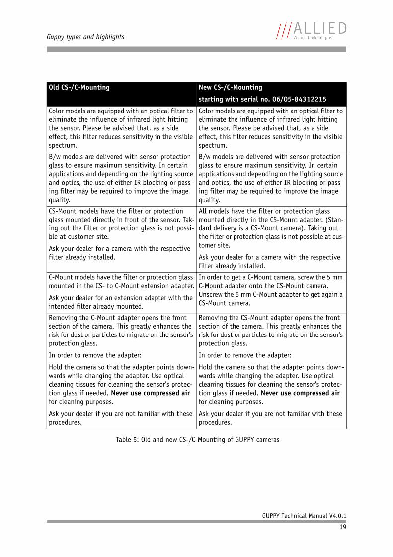
Old CS-/C-Mounting New CS-/C-Mounting
starting with serial no. 06/05-84312215
Color models are equipped with an optical filter to eliminate the influence of infrared light hitting the sensor. Please be advised that, as a side effect, this filter reduces sensitivity in the visible spectrum.
Color models are equipped with an optical filter to eliminate the influence of infrared light hitting the sensor. Please be advised that, as a side effect, this filter reduces sensitivity in the visible spectrum.
B/w models are delivered with sensor protection glass to ensure maximum sensitivity. In certain applications and depending on the lighting source and optics, the use of either IR blocking or pass-ing filter may be required to improve the image quality.
B/w models are delivered with sensor protection glass to ensure maximum sensitivity. In certain applications and depending on the lighting source and optics, the use of either IR blocking or pass-ing filter may be required to improve the image quality.
CS-Mount models have the filter or protection glass mounted directly in front of the sensor. Tak-ing out the filter or protection glass is not possi-ble at customer site.
Ask your dealer for a camera with the respective filter already installed.
All models have the filter or protection glass mounted directly in the CS-Mount adapter. (Stan-dard delivery is a CS-Mount camera). Taking out the filter or protection glass is not possible at cus-tomer site.
Ask your dealer for a camera with the respective filter already installed.
C-Mount models have the filter or protection glass mounted in the CS- to C-Mount extension adapter.
Ask your dealer for an extension adapter with the intended filter already mounted.
In order to get a C-Mount camera, screw the 5 mm C-Mount adapter onto the CS-Mount camera. Unscrew the 5 mm C-Mount adapter to get again a CS-Mount camera.
Removing the C-Mount adapter opens the front section of the camera. This greatly enhances the risk for dust or particles to migrate on the sensor's protection glass.
In order to remove the adapter:
Hold the camera so that the adapter points down-wards while changing the adapter. Use optical cleaning tissues for cleaning the sensor's protec-tion glass if needed. Never use compressed air for cleaning purposes.
Ask your dealer if you are not familiar with these procedures.
Removing the CS-Mount adapter opens the front section of the camera. This greatly enhances the risk for dust or particles to migrate on the sensor's protection glass.
In order to remove the adapter:
Hold the camera so that the adapter points down-wards while changing the adapter. Use optical cleaning tissues for cleaning the sensor's protec-tion glass if needed. Never use compressed air for cleaning purposes.
Ask your dealer if you are not familiar with these procedures.
Table 5: Old and new CS-/C-Mounting of GUPPY cameras

Guppy types and highlights
GUPPY Technical Manual V4.0.1
20
Warning Mount/dismount lenses and filters in a dust-free environ-ment, and do not use compressed air (which can push dust into cameras and lenses).
Use only optical quality tissue/cloth if you must clean a lens or filter.
System components
GUPPY Technical Manual V4.0.1
21
System components
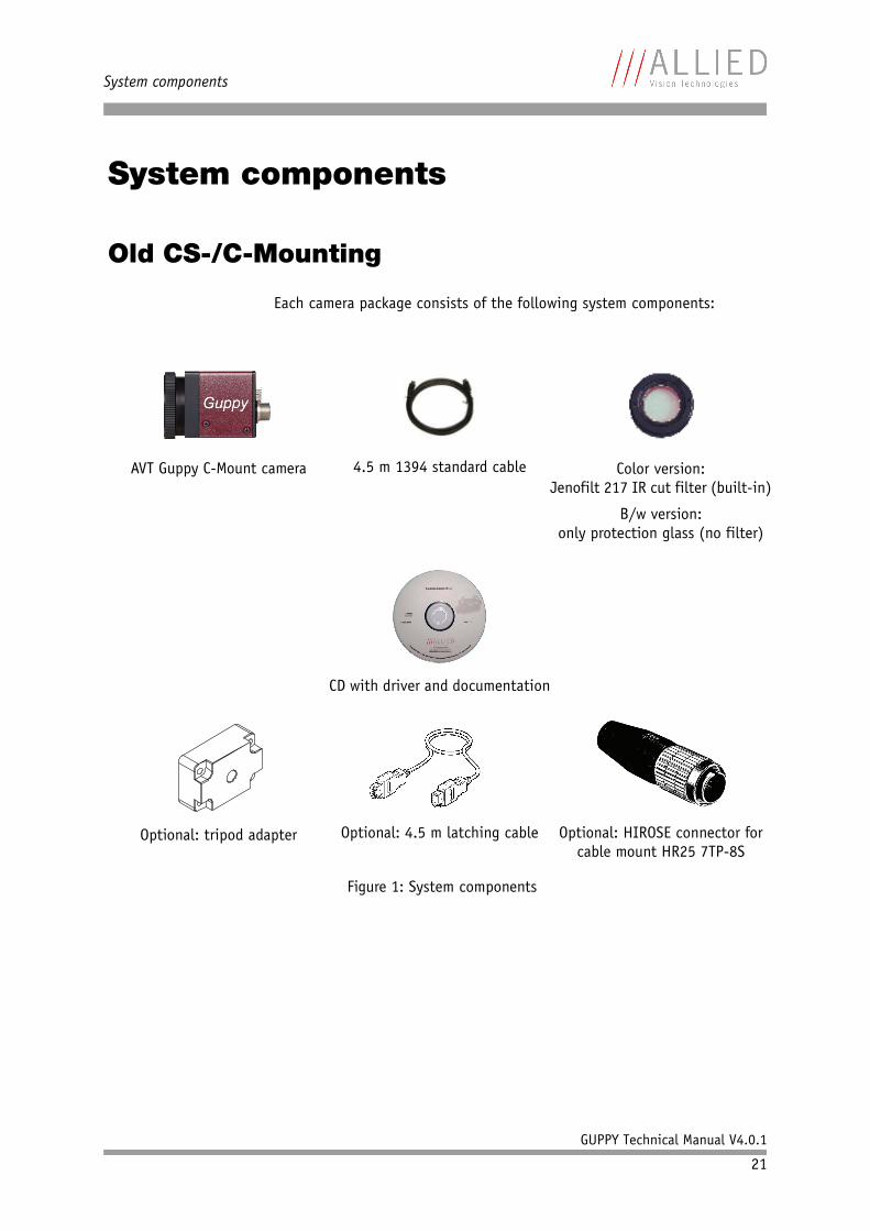
Old CS-/C-Mounting
Each camera package consists of the following system components:
AVT Guppy C-Mount camera 4.5 m 1394 standard cable Color version:Jenofilt 217 IR cut filter (built-in)
B/w version:only protection glass (no filter)
CD with driver and documentation
Optional: tripod adapter Optional: 4.5 m latching cable Optional: HIROSE connector for cable mount HR25 7TP-8S
Figure 1: System components
System components
GUPPY Technical Manual V4.0.1
22
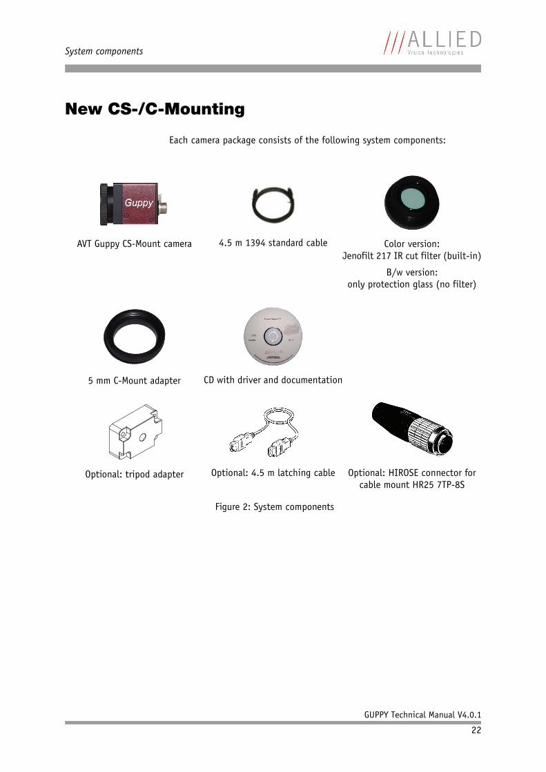
New CS-/C-Mounting
Each camera package consists of the following system components:
AVT Guppy CS-Mount camera 4.5 m 1394 standard cable Color version:Jenofilt 217 IR cut filter (built-in)
B/w version:only protection glass (no filter)
5 mm C-Mount adapter CD with driver and documentation
Optional: tripod adapter Optional: 4.5 m latching cable Optional: HIROSE connector for cable mount HR25 7TP-8S
Figure 2: System components
System components
GUPPY Technical Manual V4.0.1
23
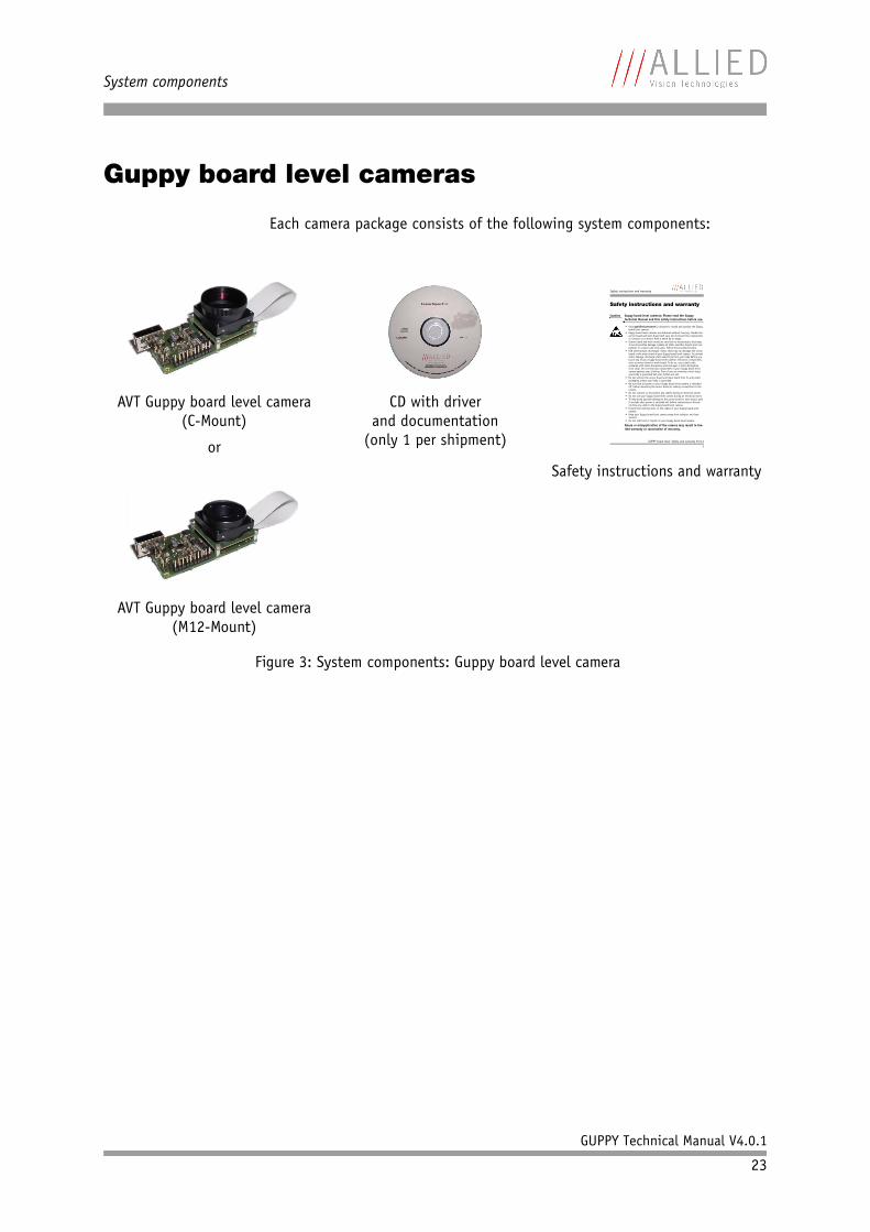
Guppy board level cameras
Each camera package consists of the following system components:
AVT Guppy board level camera(C-Mount)
or
AVT Guppy board level camera(M12-Mount)
CD with driverand documentation
(only 1 per shipment)
Safety instructions and warranty
Figure 3: System components: Guppy board level camera
Safety instructions and warranty
GUPPY board level: Safety and warranty V3.0.2
1
Safety instructions and warranty
Caution Guppy board level cameras: Please read the Guppy Technical Manual and this safety instructions before use.
• Only qualified personnel is allowed to install and operate the Guppy board level camera.
• Guppy board level cameras are delivered without housing. Handle the sensor board and main board with care. Do not touch the components or contacts on a board. Hold a board by its edges.
• Sensor board and main board are sensitive to electrostatic discharge. To avoid possible damage, handle all static-sensitive boards and com-ponents in a static-safe work area. Follow the procedures below.
• ESD (electrostatic discharge): Static electricity can damage the sensor board or the main board of your Guppy board level camera. To prevent static damage, discharge static electricity from your body before you touch any of your Guppy board level camera’s electronic components, such as sensor board or main board. To do so, use a static-safe workarea with static-dissipative mat and wear a static-dissipative wrist strap. Do not hold any components of your Guppy board level camera against your clothing. Even if you are wearing a wrist strap, your body is grounded but your clothes are not.
• Do not remove the sensor board and main board from its anti-static packaging unless your body is grounded.
• Be sure that all power to your Guppy board level camera is switched off, before mounting the sensor board or making connections to the camera.
• Do not connect or disconnect any cables during an electrical storm.• Do not use your Guppy board level camera during an electrical storm.• To help avoid possible damage to the sensor board or main board, wait
5 seconds after power is switched off, before connecting or discon-necting any cable to the Guppy board level camera.
• Ensure that nothing rests on the cables of your Guppy board level camera.
• Keep your Guppy board level camera away from radiators and heat sources.
• Do not spill food or liquids on your Guppy board level camera.
Abuse or misapplication of the camera may result in lim-ited warranty or cancelation of warranty.
System components
GUPPY Technical Manual V4.0.1
24
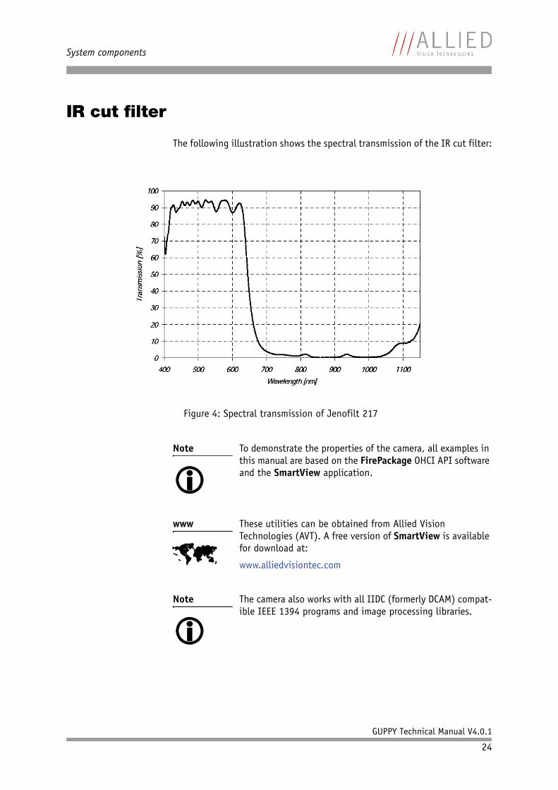
IR cut filter
The following illustration shows the spectral transmission of the IR cut filter:
Figure 4: Spectral transmission of Jenofilt 217
Note To demonstrate the properties of the camera, all examples in this manual are based on the FirePackage OHCI API software and the SmartView application.
www These utilities can be obtained from Allied Vision Technologies (AVT). A free version of SmartView is available for download at:
www.alliedvisiontec.com
Note The camera also works with all IIDC (formerly DCAM) compat-ible IEEE 1394 programs and image processing libraries.
System components
GUPPY Technical Manual V4.0.1
25
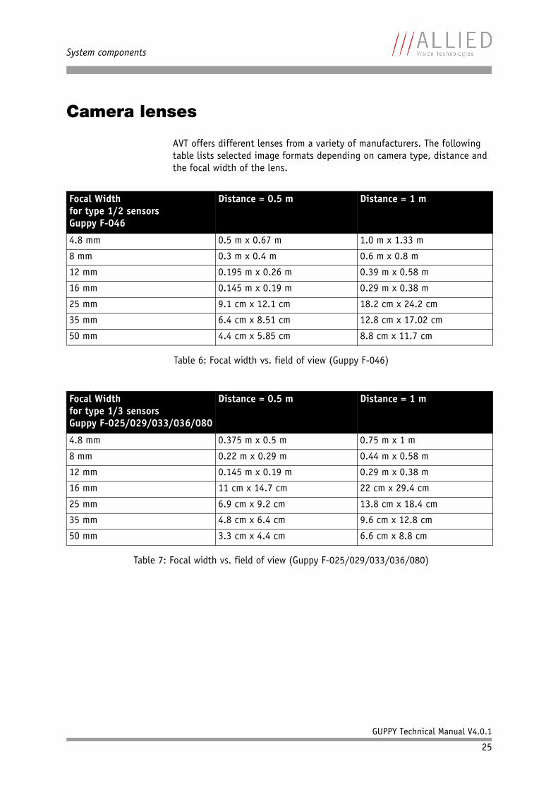
Camera lenses
AVT offers different lenses from a variety of manufacturers. The following table lists selected image formats depending on camera type, distance and the focal width of the lens.
Focal Widthfor type 1/2 sensorsGuppy F-046
Distance = 0.5 m Distance = 1 m
4.8 mm 0.5 m x 0.67 m 1.0 m x 1.33 m
8 mm 0.3 m x 0.4 m 0.6 m x 0.8 m
12 mm 0.195 m x 0.26 m 0.39 m x 0.58 m
16 mm 0.145 m x 0.19 m 0.29 m x 0.38 m
25 mm 9.1 cm x 12.1 cm 18.2 cm x 24.2 cm
35 mm 6.4 cm x 8.51 cm 12.8 cm x 17.02 cm
50 mm 4.4 cm x 5.85 cm 8.8 cm x 11.7 cm
Table 6: Focal width vs. field of view (Guppy F-046)
Focal Widthfor type 1/3 sensorsGuppy F-025/029/033/036/080
Distance = 0.5 m Distance = 1 m
4.8 mm 0.375 m x 0.5 m 0.75 m x 1 m
8 mm 0.22 m x 0.29 m 0.44 m x 0.58 m
12 mm 0.145 m x 0.19 m 0.29 m x 0.38 m
16 mm 11 cm x 14.7 cm 22 cm x 29.4 cm
25 mm 6.9 cm x 9.2 cm 13.8 cm x 18.4 cm
35 mm 4.8 cm x 6.4 cm 9.6 cm x 12.8 cm
50 mm 3.3 cm x 4.4 cm 6.6 cm x 8.8 cm
Table 7: Focal width vs. field of view (Guppy F-025/029/033/036/080)
Specifications
GUPPY Technical Manual V4.0.1
26
Specifications
Guppy F-033B
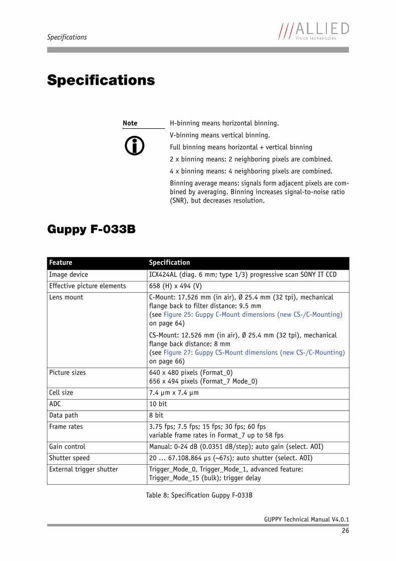
Note H-binning means horizontal binning.
V-binning means vertical binning.
Full binning means horizontal + vertical binning
2 x binning means: 2 neighboring pixels are combined.
4 x binning means: 4 neighboring pixels are combined.
Binning average means: signals form adjacent pixels are com-bined by averaging. Binning increases signal-to-noise ratio (SNR), but decreases resolution.
Feature Specification
Image device ICX424AL (diag. 6 mm; type 1/3) progressive scan SONY IT CCD
Effective picture elements 658 (H) x 494 (V)
Lens mount C-Mount: 17.526 mm (in air), Ø 25.4 mm (32 tpi), mechanical flange back to filter distance: 9.5 mm(see Figure 25: Guppy C-Mount dimensions (new CS-/C-Mounting) on page 64)
CS-Mount: 12.526 mm (in air), Ø 25.4 mm (32 tpi), mechanical flange back distance: 8 mm(see Figure 27: Guppy CS-Mount dimensions (new CS-/C-Mounting) on page 66)
Picture sizes 640 x 480 pixels (Format_0)656 x 494 pixels (Format_7 Mode_0)
Cell size 7.4 µm x 7.4 µm
ADC 10 bit
Data path 8 bit
Frame rates 3.75 fps; 7.5 fps; 15 fps; 30 fps; 60 fpsvariable frame rates in Format_7 up to 58 fps
Gain control Manual: 0-24 dB (0.0351 dB/step); auto gain (select. AOI)
Shutter speed 20 … 67.108.864 µs (~67s); auto shutter (select. AOI)
External trigger shutter Trigger_Mode_0, Trigger_Mode_1, advanced feature: Trigger_Mode_15 (bulk); trigger delay
Table 8: Specification Guppy F-033B
Specifications
GUPPY Technical Manual V4.0.1
27
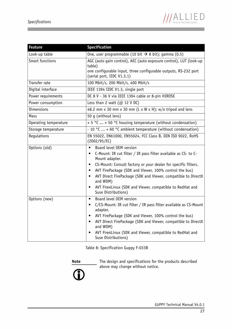
Look-up table One, user programmable (10 bit 8 bit); gamma (0.5)
Smart functions AGC (auto gain control), AEC (auto exposure control), LUT (look-up table)one configurable input, three configurable outputs, RS-232 port (serial port, IIDC V1.3.1)
Transfer rate 100 Mbit/s, 200 Mbit/s, 400 Mbit/s
Digital interface IEEE 1394 IIDC V1.3, single port
Power requirements DC 8 V - 36 V via IEEE 1394 cable or 8-pin HIROSE
Power consumption Less than 2 watt (@ 12 V DC)
Dimensions 48.2 mm x 30 mm x 30 mm (L x W x H); w/o tripod and lens
Mass 50 g (without lens)
Operating temperature + 5 °C ... + 50 °C housing temperature (without condensation)
Storage temperature - 10 °C ... + 60 °C ambient temperature (without condensation)
Regulations EN 55022, EN61000, EN55024, FCC Class B, DIN ISO 9022, RoHS (2002/95/EC)
Options (old) • Board level OEM version• C-Mount: IR cut filter / IR pass filter available as CS- to C-
Mount adapter.• CS-Mount: Consult factory or your dealer for specific filters.• AVT FirePackage (SDK and Viewer, 100% control the bus)• AVT Direct FirePackage (SDK and Viewer, compatible to DirectX
and WDM)• AVT Fire4Linux (SDK and Viewer, compatible to RedHat and
Suse Distributions)
Options (new) • Board level OEM version• C/CS-Mount: IR cut filter / IR pass filter available as CS-Mount
adapter.• AVT FirePackage (SDK and Viewer, 100% control the bus)• AVT Direct FirePackage (SDK and Viewer, compatible to DirectX
and WDM)• AVT Fire4Linux (SDK and Viewer, compatible to RedHat and
Suse Distributions)
Note The design and specifications for the products described above may change without notice.
Feature Specification
Table 8: Specification Guppy F-033B

Specifications
GUPPY Technical Manual V4.0.1
28
Guppy F-033C
Feature Specification
Image device ICX424AQ (diag. 6 mm; type 1/3) progressive scan SONY IT CCD
Effective picture elements 658 (H) x 494 (V)
Lens mount C-Mount: 17.526 mm (in air), Ø 25.4 mm (32 tpi), mechanical flange back to filter distance: 9.5 mm(see Figure 25: Guppy C-Mount dimensions (new CS-/C-Mounting) on page 64)
CS-Mount: 12.526 mm (in air), Ø 25.4 mm (32 tpi), mechanical flange back distance: 8 mm(see Figure 27: Guppy CS-Mount dimensions (new CS-/C-Mounting) on page 66)
Picture sizes 640 x 480 pixels (Format_0)656 x 494 pixels (Format_7 Mode_0)
Cell size 7.4 µm x 7.4 µm
ADC 10 bit
Color modes Raw8
Data path 8 bit
Frame rates 3.75 fps; 7.5 fps; 15 fps; 30 fps; 60 fpsvariable frame rates in Format_7 up to 58 fps
Gain control Manual: 0-24 dB (0.0351 dB/step); auto gain (select. AOI)
Shutter speed 20 … 67.108.864 µs (~67s); auto shutter (select. AOI)
External trigger shutter Trigger_Mode_0, Trigger_Mode_1, advanced feature: Trigger_Mode_15 (bulk); trigger delay
Look-up table One, user programmable (10 bit 8 bit); gamma (0.5)
Smart functions AGC (auto gain control), AEC (auto exposure control), AWB (auto white balance), LUT (look-up table)one configurable input, three configurable outputs, RS-232 port (serial port, IIDC V1.3.1)
Transfer rate 100 Mbit/s, 200 Mbit/s, 400 Mbit/s
Digital interface IEEE 1394 IIDC V1.3, single port
Power requirements DC 8 V - 36 V via IEEE 1394 cable or 8-pin HIROSE
Power consumption Less than 2 watt (@ 12 V DC)
Dimensions 48.2 mm x 30 mm x 30 mm (L x W x H); w/o tripod and lens
Mass 50 g (without lens)
Operating temperature + 5 °C ... + 50 °C housing temperature (without condensation)
Storage temperature - 10 °C ... + 60 °C ambient temperature (without condensation)
Table 9: Specification Guppy F-033C
Specifications
GUPPY Technical Manual V4.0.1
29
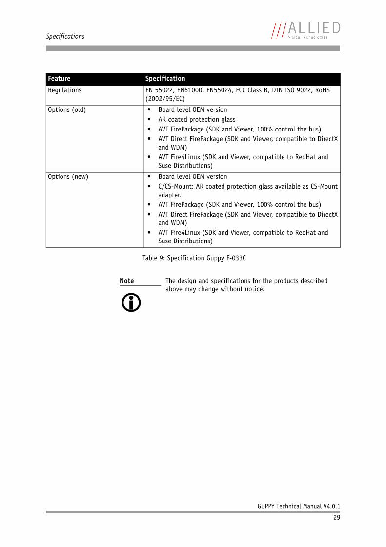
Regulations EN 55022, EN61000, EN55024, FCC Class B, DIN ISO 9022, RoHS (2002/95/EC)
Options (old) • Board level OEM version• AR coated protection glass• AVT FirePackage (SDK and Viewer, 100% control the bus)• AVT Direct FirePackage (SDK and Viewer, compatible to DirectX
and WDM)• AVT Fire4Linux (SDK and Viewer, compatible to RedHat and
Suse Distributions)
Options (new) • Board level OEM version• C/CS-Mount: AR coated protection glass available as CS-Mount
adapter.• AVT FirePackage (SDK and Viewer, 100% control the bus)• AVT Direct FirePackage (SDK and Viewer, compatible to DirectX
and WDM)• AVT Fire4Linux (SDK and Viewer, compatible to RedHat and
Suse Distributions)
Note The design and specifications for the products described above may change without notice.
Feature Specification
Table 9: Specification Guppy F-033C
Specifications
GUPPY Technical Manual V4.0.1
30
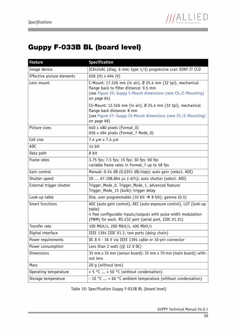
Guppy F-033B BL (board level)
Feature Specification
Image device ICX424AL (diag. 6 mm; type 1/3) progressive scan SONY IT CCD
Effective picture elements 658 (H) x 494 (V)
Lens mount C-Mount: 17.526 mm (in air), Ø 25.4 mm (32 tpi), mechanical flange back to filter distance: 9.5 mm(see Figure 25: Guppy C-Mount dimensions (new CS-/C-Mounting) on page 64)
CS-Mount: 12.526 mm (in air), Ø 25.4 mm (32 tpi), mechanical flange back distance: 8 mm(see Figure 27: Guppy CS-Mount dimensions (new CS-/C-Mounting) on page 66)
Picture sizes 640 x 480 pixels (Format_0)656 x 494 pixels (Format_7 Mode_0)
Cell size 7.4 µm x 7.4 µm
ADC 14 bit
Data path 8 bit
Frame rates 3.75 fps; 7.5 fps; 15 fps; 30 fps; 60 fpsvariable frame rates in Format_7 up to 58 fps
Gain control Manual: 0-24 dB (0.0351 dB/step); auto gain (select. AOI)
Shutter speed 20 … 67.108.864 µs (~67s); auto shutter (select. AOI)
External trigger shutter Trigger_Mode_0, Trigger_Mode_1, advanced feature: Trigger_Mode_15 (bulk); trigger delay
Look-up table One, user programmable (10 bit 8 bit); gamma (0.5)
Smart functions AGC (auto gain control), AEC (auto exposure control), LUT (look-up table)4 free configurable inputs/outputs with pulse width modulation (PWM) for each, RS-232 port (serial port, IIDC V1.31)
Transfer rate 100 Mbit/s, 200 Mbit/s, 400 Mbit/s
Digital interface IEEE 1394 IIDC V1.3, two ports (daisy chain)
Power requirements DC 8 V - 36 V via IEEE 1394 cable or 10-pin connector
Power consumption Less than 2 watt (@ 12 V DC)
Dimensions 35 mm x 35 mm (sensor board); 35 mm x 70 mm (main board); with-out lens
Mass 20 g (without lens)
Operating temperature + 5 °C ... + 50 °C (without condensation)
Storage temperature - 10 °C ... + 60 °C ambient temperature (without condensation)
Table 10: Specification Guppy F-033B BL (board level)

Specifications
GUPPY Technical Manual V4.0.1
31
Regulations EN 55022, EN61000, EN55024, FCC Class B, RoHS (2002/95/EC)
Options • C-Mount (built-in IR cut filter / protection glass)• M12-Mount (built-in IR cut filter / protection glass)• M12 lenses• 1394 adapter cable• I/O adapter cable• AVT FirePackage (SDK and Viewer, 100% control the bus)• AVT Direct FirePackage (SDK and Viewer, compatible to DirectX
and WDM)• AVT Fire4Linux (SDK and Viewer, compatible to RedHat and
Suse Distributions)
Note The design and specifications for the products described above may change without notice.
Feature Specification
Table 10: Specification Guppy F-033B BL (board level)
Specifications
GUPPY Technical Manual V4.0.1
32
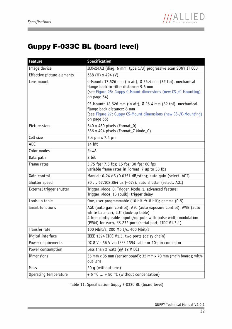
Guppy F-033C BL (board level)
Feature Specification
Image device ICX424AQ (diag. 6 mm; type 1/3) progressive scan SONY IT CCD
Effective picture elements 658 (H) x 494 (V)
Lens mount C-Mount: 17.526 mm (in air), Ø 25.4 mm (32 tpi), mechanical flange back to filter distance: 9.5 mm(see Figure 25: Guppy C-Mount dimensions (new CS-/C-Mounting) on page 64)
CS-Mount: 12.526 mm (in air), Ø 25.4 mm (32 tpi), mechanical flange back distance: 8 mm(see Figure 27: Guppy CS-Mount dimensions (new CS-/C-Mounting) on page 66)
Picture sizes 640 x 480 pixels (Format_0)656 x 494 pixels (Format_7 Mode_0)
Cell size 7.4 µm x 7.4 µm
ADC 14 bit
Color modes Raw8
Data path 8 bit
Frame rates 3.75 fps; 7.5 fps; 15 fps; 30 fps; 60 fpsvariable frame rates in Format_7 up to 58 fps
Gain control Manual: 0-24 dB (0.0351 dB/step); auto gain (select. AOI)
Shutter speed 20 … 67.108.864 µs (~67s); auto shutter (select. AOI)
External trigger shutter Trigger_Mode_0, Trigger_Mode_1, advanced feature: Trigger_Mode_15 (bulk); trigger delay
Look-up table One, user programmable (10 bit 8 bit); gamma (0.5)
Smart functions AGC (auto gain control), AEC (auto exposure control), AWB (auto white balance), LUT (look-up table)4 free configurable inputs/outputs with pulse width modulation (PWM) for each, RS-232 port (serial port, IIDC V1.3.1)
Transfer rate 100 Mbit/s, 200 Mbit/s, 400 Mbit/s
Digital interface IEEE 1394 IIDC V1.3, two ports (daisy chain)
Power requirements DC 8 V - 36 V via IEEE 1394 cable or 10-pin connector
Power consumption Less than 2 watt (@ 12 V DC)
Dimensions 35 mm x 35 mm (sensor board); 35 mm x 70 mm (main board); with-out lens
Mass 20 g (without lens)
Operating temperature + 5 °C ... + 50 °C (without condensation)
Table 11: Specification Guppy F-033C BL (board level)

Specifications
GUPPY Technical Manual V4.0.1
33
Storage temperature - 10 °C ... + 60 °C ambient temperature (without condensation)
Regulations EN 55022, EN61000, EN55024, FCC Class B, RoHS (2002/95/EC)
Options • C-Mount (built-in IR cut filter / protection glass)• M12-Mount (built-in IR cut filter / protection glass)• M12 lenses• 1394 adapter cable• I/O adapter cable• AVT FirePackage (SDK and Viewer, 100% control the bus)• AVT Direct FirePackage (SDK and Viewer, compatible to DirectX
and WDM)• AVT Fire4Linux (SDK and Viewer, compatible to RedHat and
Suse Distributions)
Note The design and specifications for the products described above may change without notice.
Feature Specification
Table 11: Specification Guppy F-033C BL (board level)
Specifications
GUPPY Technical Manual V4.0.1
34
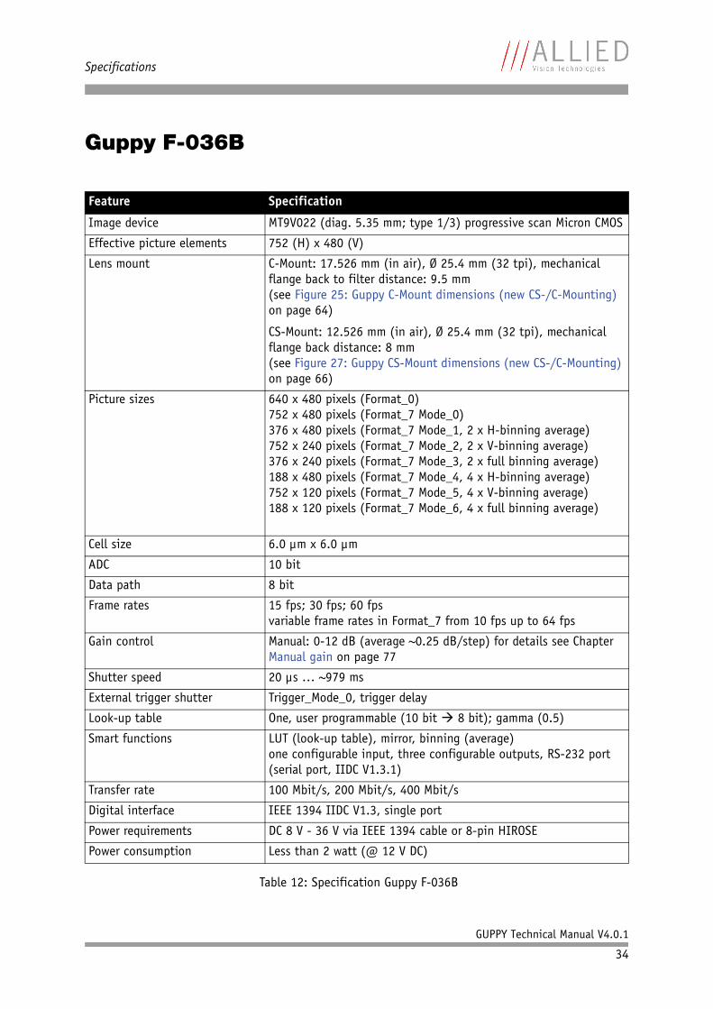
Guppy F-036B
Feature Specification
Image device MT9V022 (diag. 5.35 mm; type 1/3) progressive scan Micron CMOS
Effective picture elements 752 (H) x 480 (V)
Lens mount C-Mount: 17.526 mm (in air), Ø 25.4 mm (32 tpi), mechanical flange back to filter distance: 9.5 mm(see Figure 25: Guppy C-Mount dimensions (new CS-/C-Mounting) on page 64)
CS-Mount: 12.526 mm (in air), Ø 25.4 mm (32 tpi), mechanical flange back distance: 8 mm(see Figure 27: Guppy CS-Mount dimensions (new CS-/C-Mounting) on page 66)
Picture sizes 640 x 480 pixels (Format_0)752 x 480 pixels (Format_7 Mode_0)376 x 480 pixels (Format_7 Mode_1, 2 x H-binning average) 752 x 240 pixels (Format_7 Mode_2, 2 x V-binning average)376 x 240 pixels (Format_7 Mode_3, 2 x full binning average)188 x 480 pixels (Format_7 Mode_4, 4 x H-binning average)752 x 120 pixels (Format_7 Mode_5, 4 x V-binning average)188 x 120 pixels (Format_7 Mode_6, 4 x full binning average)
Cell size 6.0 µm x 6.0 µm
ADC 10 bit
Data path 8 bit
Frame rates 15 fps; 30 fps; 60 fpsvariable frame rates in Format_7 from 10 fps up to 64 fps
Gain control Manual: 0-12 dB (average ~0.25 dB/step) for details see Chapter Manual gain on page 77
Shutter speed 20 µs … ~979 ms
External trigger shutter Trigger_Mode_0, trigger delay
Look-up table One, user programmable (10 bit 8 bit); gamma (0.5)
Smart functions LUT (look-up table), mirror, binning (average)one configurable input, three configurable outputs, RS-232 port (serial port, IIDC V1.3.1)
Transfer rate 100 Mbit/s, 200 Mbit/s, 400 Mbit/s
Digital interface IEEE 1394 IIDC V1.3, single port
Power requirements DC 8 V - 36 V via IEEE 1394 cable or 8-pin HIROSE
Power consumption Less than 2 watt (@ 12 V DC)
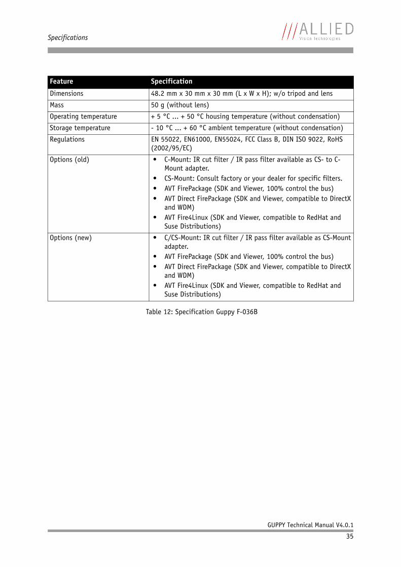
Table 12: Specification Guppy F-036B
Specifications
GUPPY Technical Manual V4.0.1
35
Dimensions 48.2 mm x 30 mm x 30 mm (L x W x H); w/o tripod and lens
Mass 50 g (without lens)
Operating temperature + 5 °C ... + 50 °C housing temperature (without condensation)
Storage temperature - 10 °C ... + 60 °C ambient temperature (without condensation)
Regulations EN 55022, EN61000, EN55024, FCC Class B, DIN ISO 9022, RoHS (2002/95/EC)
Options (old) • C-Mount: IR cut filter / IR pass filter available as CS- to C-Mount adapter.
• CS-Mount: Consult factory or your dealer for specific filters.• AVT FirePackage (SDK and Viewer, 100% control the bus)• AVT Direct FirePackage (SDK and Viewer, compatible to DirectX
and WDM)• AVT Fire4Linux (SDK and Viewer, compatible to RedHat and
Suse Distributions)
Options (new) • C/CS-Mount: IR cut filter / IR pass filter available as CS-Mount adapter.
• AVT FirePackage (SDK and Viewer, 100% control the bus)• AVT Direct FirePackage (SDK and Viewer, compatible to DirectX
and WDM)• AVT Fire4Linux (SDK and Viewer, compatible to RedHat and
Suse Distributions)
Feature Specification
Table 12: Specification Guppy F-036B
Specifications
GUPPY Technical Manual V4.0.1
36
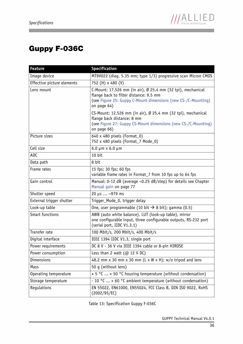
Guppy F-036C
Feature Specification
Image device MT9V022 (diag. 5.35 mm; type 1/3) progressive scan Micron CMOS
Effective picture elements 752 (H) x 480 (V)
Lens mount C-Mount: 17.526 mm (in air), Ø 25.4 mm (32 tpi), mechanical flange back to filter distance: 9.5 mm(see Figure 25: Guppy C-Mount dimensions (new CS-/C-Mounting) on page 64)
CS-Mount: 12.526 mm (in air), Ø 25.4 mm (32 tpi), mechanical flange back distance: 8 mm(see Figure 27: Guppy CS-Mount dimensions (new CS-/C-Mounting) on page 66)
Picture sizes 640 x 480 pixels (Format_0)752 x 480 pixels (Format_7 Mode_0)
Cell size 6.0 µm x 6.0 µm
ADC 10 bit
Data path 8 bit
Frame rates 15 fps; 30 fps; 60 fpsvariable frame rates in Format_7 from 10 fps up to 64 fps
Gain control Manual: 0-12 dB (average ~0.25 dB/step) for details see Chapter Manual gain on page 77
Shutter speed 20 µs … ~979 ms
External trigger shutter Trigger_Mode_0, trigger delay
Look-up table One, user programmable (10 bit 8 bit); gamma (0.5)
Smart functions AWB (auto white balance), LUT (look-up table), mirrorone configurable input, three configurable outputs, RS-232 port (serial port, IIDC V1.3.1)
Transfer rate 100 Mbit/s, 200 Mbit/s, 400 Mbit/s
Digital interface IEEE 1394 IIDC V1.3, single port
Power requirements DC 8 V - 36 V via IEEE 1394 cable or 8-pin HIROSE
Power consumption Less than 2 watt (@ 12 V DC)
Dimensions 48.2 mm x 30 mm x 30 mm (L x W x H); w/o tripod and lens
Mass 50 g (without lens)
Operating temperature + 5 °C ... + 50 °C housing temperature (without condensation)
Storage temperature - 10 °C ... + 60 °C ambient temperature (without condensation)
Regulations EN 55022, EN61000, EN55024, FCC Class B, DIN ISO 9022, RoHS (2002/95/EC)
Table 13: Specification Guppy F-036C
Specifications
GUPPY Technical Manual V4.0.1
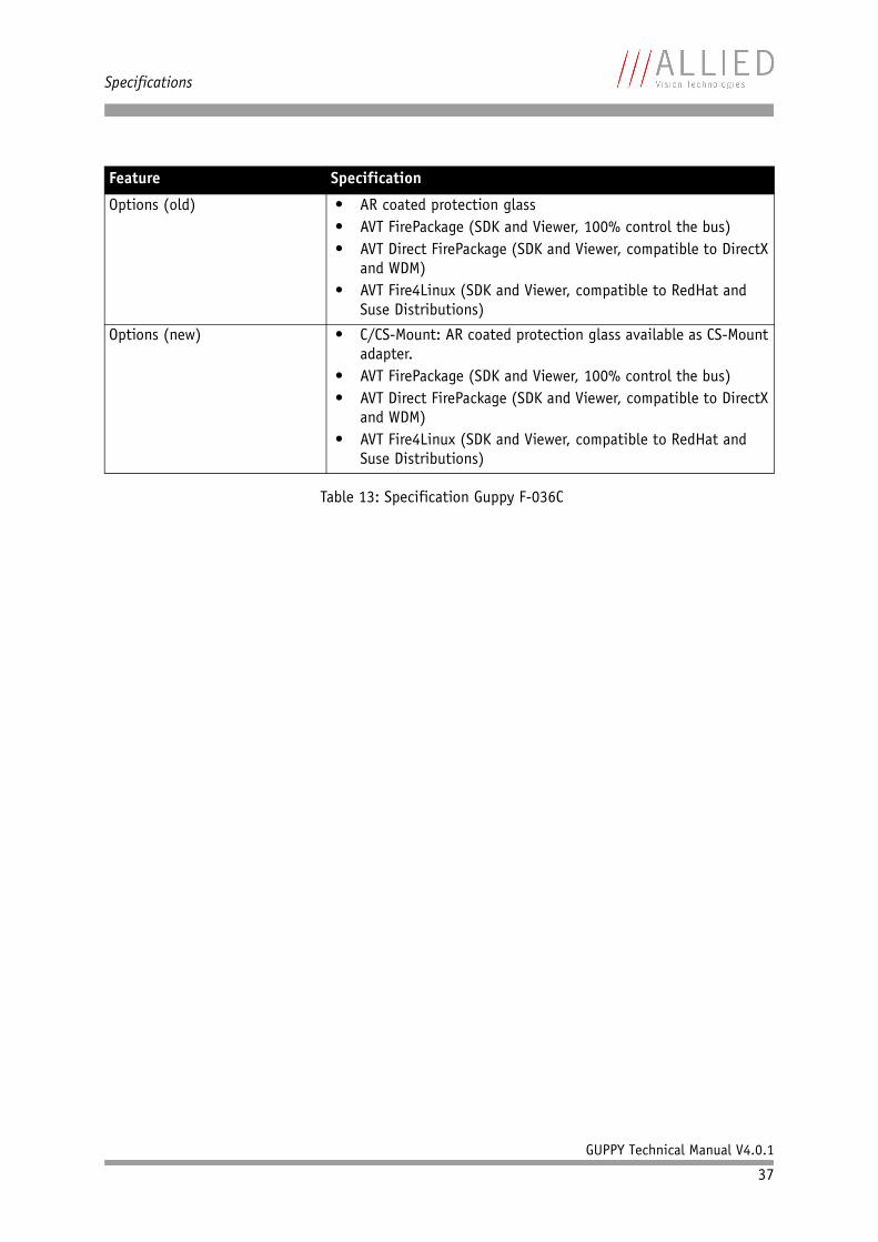
37
Options (old) • AR coated protection glass• AVT FirePackage (SDK and Viewer, 100% control the bus)• AVT Direct FirePackage (SDK and Viewer, compatible to DirectX
and WDM)• AVT Fire4Linux (SDK and Viewer, compatible to RedHat and
Suse Distributions)
Options (new) • C/CS-Mount: AR coated protection glass available as CS-Mount adapter.
• AVT FirePackage (SDK and Viewer, 100% control the bus)• AVT Direct FirePackage (SDK and Viewer, compatible to DirectX
and WDM)• AVT Fire4Linux (SDK and Viewer, compatible to RedHat and
Suse Distributions)
Feature Specification
Table 13: Specification Guppy F-036C
Specifications
GUPPY Technical Manual V4.0.1
38
Guppy F-046B
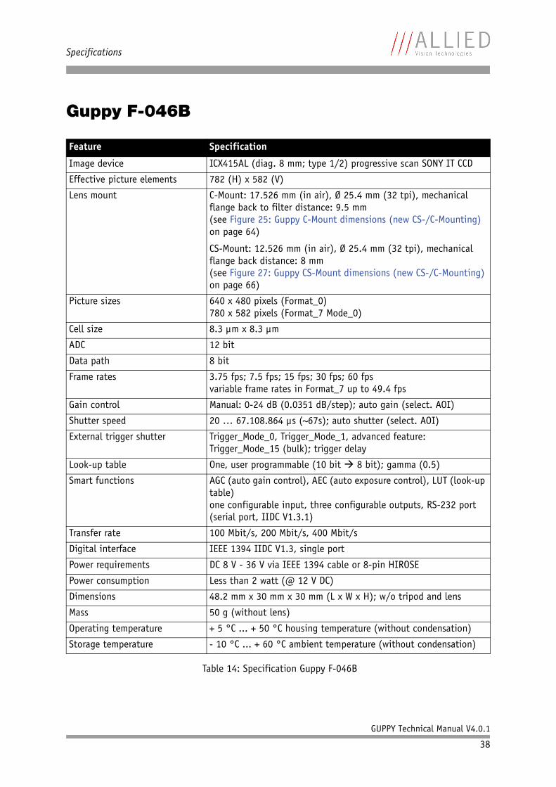
Feature Specification
Image device ICX415AL (diag. 8 mm; type 1/2) progressive scan SONY IT CCD
Effective picture elements 782 (H) x 582 (V)
Lens mount C-Mount: 17.526 mm (in air), Ø 25.4 mm (32 tpi), mechanical flange back to filter distance: 9.5 mm(see Figure 25: Guppy C-Mount dimensions (new CS-/C-Mounting) on page 64)
CS-Mount: 12.526 mm (in air), Ø 25.4 mm (32 tpi), mechanical flange back distance: 8 mm(see Figure 27: Guppy CS-Mount dimensions (new CS-/C-Mounting) on page 66)
Picture sizes 640 x 480 pixels (Format_0)780 x 582 pixels (Format_7 Mode_0)
Cell size 8.3 µm x 8.3 µm
ADC 12 bit
Data path 8 bit
Frame rates 3.75 fps; 7.5 fps; 15 fps; 30 fps; 60 fpsvariable frame rates in Format_7 up to 49.4 fps
Gain control Manual: 0-24 dB (0.0351 dB/step); auto gain (select. AOI)
Shutter speed 20 … 67.108.864 µs (~67s); auto shutter (select. AOI)
External trigger shutter Trigger_Mode_0, Trigger_Mode_1, advanced feature: Trigger_Mode_15 (bulk); trigger delay
Look-up table One, user programmable (10 bit 8 bit); gamma (0.5)
Smart functions AGC (auto gain control), AEC (auto exposure control), LUT (look-up table)one configurable input, three configurable outputs, RS-232 port (serial port, IIDC V1.3.1)
Transfer rate 100 Mbit/s, 200 Mbit/s, 400 Mbit/s
Digital interface IEEE 1394 IIDC V1.3, single port
Power requirements DC 8 V - 36 V via IEEE 1394 cable or 8-pin HIROSE
Power consumption Less than 2 watt (@ 12 V DC)
Dimensions 48.2 mm x 30 mm x 30 mm (L x W x H); w/o tripod and lens
Mass 50 g (without lens)
Operating temperature + 5 °C ... + 50 °C housing temperature (without condensation)
Storage temperature - 10 °C ... + 60 °C ambient temperature (without condensation)
Table 14: Specification Guppy F-046B
Specifications
GUPPY Technical Manual V4.0.1
39
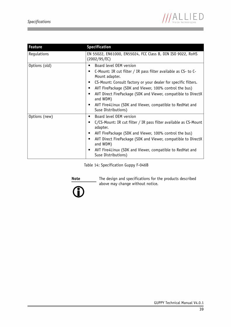
Regulations EN 55022, EN61000, EN55024, FCC Class B, DIN ISO 9022, RoHS (2002/95/EC)
Options (old) • Board level OEM version• C-Mount: IR cut filter / IR pass filter available as CS- to C-
Mount adapter.• CS-Mount: Consult factory or your dealer for specific filters.• AVT FirePackage (SDK and Viewer, 100% control the bus)• AVT Direct FirePackage (SDK and Viewer, compatible to DirectX
and WDM)• AVT Fire4Linux (SDK and Viewer, compatible to RedHat and
Suse Distributions)
Options (new) • Board level OEM version• C/CS-Mount: IR cut filter / IR pass filter available as CS-Mount
adapter.• AVT FirePackage (SDK and Viewer, 100% control the bus)• AVT Direct FirePackage (SDK and Viewer, compatible to DirectX
and WDM)• AVT Fire4Linux (SDK and Viewer, compatible to RedHat and
Suse Distributions)
Note The design and specifications for the products described above may change without notice.
Feature Specification
Table 14: Specification Guppy F-046B
Specifications
GUPPY Technical Manual V4.0.1
40
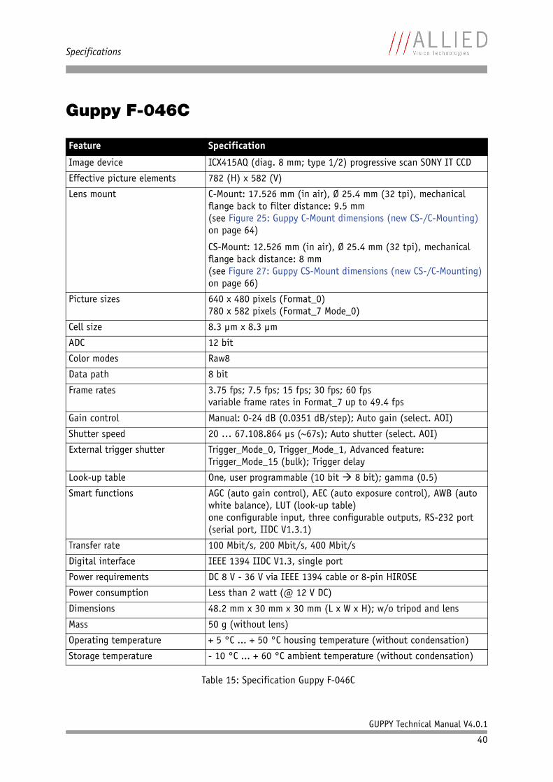
Guppy F-046C
Feature Specification
Image device ICX415AQ (diag. 8 mm; type 1/2) progressive scan SONY IT CCD
Effective picture elements 782 (H) x 582 (V)
Lens mount C-Mount: 17.526 mm (in air), Ø 25.4 mm (32 tpi), mechanical flange back to filter distance: 9.5 mm(see Figure 25: Guppy C-Mount dimensions (new CS-/C-Mounting) on page 64)
CS-Mount: 12.526 mm (in air), Ø 25.4 mm (32 tpi), mechanical flange back distance: 8 mm(see Figure 27: Guppy CS-Mount dimensions (new CS-/C-Mounting) on page 66)
Picture sizes 640 x 480 pixels (Format_0)780 x 582 pixels (Format_7 Mode_0)
Cell size 8.3 µm x 8.3 µm
ADC 12 bit
Color modes Raw8
Data path 8 bit
Frame rates 3.75 fps; 7.5 fps; 15 fps; 30 fps; 60 fpsvariable frame rates in Format_7 up to 49.4 fps
Gain control Manual: 0-24 dB (0.0351 dB/step); Auto gain (select. AOI)
Shutter speed 20 … 67.108.864 µs (~67s); Auto shutter (select. AOI)
External trigger shutter Trigger_Mode_0, Trigger_Mode_1, Advanced feature: Trigger_Mode_15 (bulk); Trigger delay
Look-up table One, user programmable (10 bit 8 bit); gamma (0.5)
Smart functions AGC (auto gain control), AEC (auto exposure control), AWB (auto white balance), LUT (look-up table)one configurable input, three configurable outputs, RS-232 port (serial port, IIDC V1.3.1)
Transfer rate 100 Mbit/s, 200 Mbit/s, 400 Mbit/s
Digital interface IEEE 1394 IIDC V1.3, single port
Power requirements DC 8 V - 36 V via IEEE 1394 cable or 8-pin HIROSE
Power consumption Less than 2 watt (@ 12 V DC)
Dimensions 48.2 mm x 30 mm x 30 mm (L x W x H); w/o tripod and lens
Mass 50 g (without lens)
Operating temperature + 5 °C ... + 50 °C housing temperature (without condensation)
Storage temperature - 10 °C ... + 60 °C ambient temperature (without condensation)
Table 15: Specification Guppy F-046C

Specifications
GUPPY Technical Manual V4.0.1
41
Regulations EN 55022, EN61000, EN55024, FCC Class B, DIN ISO 9022, RoHS (2002/95/EC)
Options (old) • Board level OEM version• AR coated protection glass• AVT FirePackage (SDK and Viewer, 100% control the bus)• AVT Direct FirePackage (SDK and Viewer, compatible to DirectX
and WDM)• AVT Fire4Linux (SDK and Viewer, compatible to RedHat and
Suse Distributions)
Options (new) • Board level OEM version• C/CS-Mount: AR coated protection glass available as CS-Mount
adapter.• AVT FirePackage (SDK and Viewer, 100% control the bus)• AVT Direct FirePackage (SDK and Viewer, compatible to DirectX
and WDM)• AVT Fire4Linux (SDK and Viewer, compatible to RedHat and
Suse Distributions)
Note The design and specifications for the products described above may change without notice.
Feature Specification
Table 15: Specification Guppy F-046C
Specifications
GUPPY Technical Manual V4.0.1
42
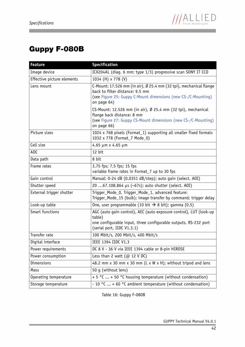
Guppy F-080B
Feature Specification
Image device ICX204AL (diag. 6 mm; type 1/3) progressive scan SONY IT CCD
Effective picture elements 1034 (H) x 778 (V)
Lens mount C-Mount: 17.526 mm (in air), Ø 25.4 mm (32 tpi), mechanical flange back to filter distance: 9.5 mm(see Figure 25: Guppy C-Mount dimensions (new CS-/C-Mounting) on page 64)
CS-Mount: 12.526 mm (in air), Ø 25.4 mm (32 tpi), mechanical flange back distance: 8 mm(see Figure 27: Guppy CS-Mount dimensions (new CS-/C-Mounting) on page 66)
Picture sizes 1024 x 768 pixels (Format_1) supporting all smaller fixed formats1032 x 778 (Format_7 Mode_0)
Cell size 4.65 µm x 4.65 µm
ADC 12 bit
Data path 8 bit
Frame rates 3.75 fps; 7.5 fps; 15 fpsvariable frame rates in Format_7 up to 30 fps
Gain control Manual: 0-24 dB (0.0351 dB/step); auto gain (select. AOI)
Shutter speed 20 …67.108.864 µs (~67s); auto shutter (select. AOI)
External trigger shutter Trigger_Mode_0, Trigger_Mode_1, advanced feature: Trigger_Mode_15 (bulk); image transfer by command; trigger delay
Look-up table One, user programmable (10 bit 8 bit); gamma (0.5)
Smart functions AGC (auto gain control), AEC (auto exposure control), LUT (look-up table)one configurable input, three configurable outputs, RS-232 port (serial port, IIDC V1.3.1)
Transfer rate 100 Mbit/s, 200 Mbit/s, 400 Mbit/s
Digital interface IEEE 1394 IIDC V1.3
Power requirements DC 8 V - 36 V via IEEE 1394 cable or 8-pin HIROSE
Power consumption Less than 2 watt (@ 12 V DC)
Dimensions 48.2 mm x 30 mm x 30 mm (L x W x H); without tripod and lens
Mass 50 g (without lens)
Operating temperature + 5 °C ... + 50 °C housing temperature (without condensation)
Storage temperature - 10 °C ... + 60 °C ambient temperature (without condensation)
Table 16: Guppy F-080B

Specifications
GUPPY Technical Manual V4.0.1
43
Regulations EN 55022, EN 61000, EN 55024, FCC class B, DIN ISO 9022, RoHS (2002/95/EC)
Options (old) • Board level OEM version• C-Mount: IR cut filter / IR pass filter available as CS- to C-
Mount adapter.• CS-Mount: Consult factory or your dealer for specific filters.• AVT FirePackage (SDK and Viewer, 100% control the bus)• AVT Direct FirePackage (SDK and Viewer, compatible to DirectX
and WDM)• AVT Fire4Linux (SDK and Viewer, compatible to RedHat and
Suse Distributions)
Options (new) • Board level OEM version• C/CS-Mount: IR cut filter / IR pass filter available as CS-Mount
adapter.• AVT FirePackage (SDK and Viewer, 100% control the bus)• AVT Direct FirePackage (SDK and Viewer, compatible to DirectX
and WDM)• AVT Fire4Linux (SDK and Viewer, compatible to RedHat and
Suse Distributions)
Note The design and specifications for the products described above may change without notice.
Feature Specification
Table 16: Guppy F-080B
Specifications
GUPPY Technical Manual V4.0.1
44
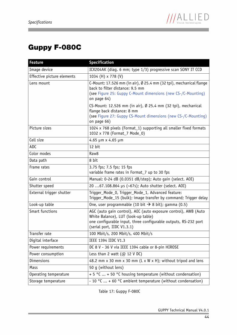
Guppy F-080C
Feature Specification
Image device ICX204AK (diag. 6 mm; type 1/3) progressive scan SONY IT CCD
Effective picture elements 1034 (H) x 778 (V)
Lens mount C-Mount: 17.526 mm (in air), Ø 25.4 mm (32 tpi), mechanical flange back to filter distance: 9.5 mm(see Figure 25: Guppy C-Mount dimensions (new CS-/C-Mounting) on page 64)
CS-Mount: 12.526 mm (in air), Ø 25.4 mm (32 tpi), mechanical flange back distance: 8 mm(see Figure 27: Guppy CS-Mount dimensions (new CS-/C-Mounting) on page 66)
Picture sizes 1024 x 768 pixels (Format_1) supporting all smaller fixed formats1032 x 778 (Format_7 Mode_0)
Cell size 4.65 µm x 4.65 µm
ADC 12 bit
Color modes Raw8
Data path 8 bit
Frame rates 3.75 fps; 7.5 fps; 15 fpsvariable frame rates in Format_7 up to 30 fps
Gain control Manual: 0-24 dB (0.0351 dB/step); Auto gain (select. AOI)
Shutter speed 20 …67.108.864 µs (~67s); Auto shutter (select. AOI)
External trigger shutter Trigger_Mode_0, Trigger_Mode_1, Advanced feature: Trigger_Mode_15 (bulk); image transfer by command; Trigger delay
Look-up table One, user programmable (10 bit 8 bit); gamma (0.5)
Smart functions AGC (auto gain control), AEC (auto exposure control), AWB (Auto White Balance), LUT (look-up table)one configurable input, three configurable outputs, RS-232 port (serial port, IIDC V1.3.1)
Transfer rate 100 Mbit/s, 200 Mbit/s, 400 Mbit/s
Digital interface IEEE 1394 IIDC V1.3
Power requirements DC 8 V - 36 V via IEEE 1394 cable or 8-pin HIROSE
Power consumption Less than 2 watt (@ 12 V DC)
Dimensions 48.2 mm x 30 mm x 30 mm (L x W x H); without tripod and lens
Mass 50 g (without lens)
Operating temperature + 5 °C ... + 50 °C housing temperature (without condensation)
Storage temperature - 10 °C ... + 60 °C ambient temperature (without condensation)
Table 17: Guppy F-080C

Specifications
GUPPY Technical Manual V4.0.1
45
Regulations EN 55022, EN 61000, EN 55024, FCC class B, DIN ISO 9022, RoHS (2002/95/EC)
Options (old) • Board level OEM version• AR coated protection glass• AVT FirePackage (SDK and Viewer, 100% control the bus)• AVT Direct FirePackage (SDK and Viewer, compatible to DirectX
and WDM)• AVT Fire4Linux (SDK and Viewer, compatible to RedHat and
Suse Distributions)
Options (new) • Board level OEM version• C/CS-Mount: AR coated protection glass available as CS-Mount
adapter.• AVT FirePackage (SDK and Viewer, 100% control the bus)• AVT Direct FirePackage (SDK and Viewer, compatible to DirectX
and WDM)• AVT Fire4Linux (SDK and Viewer, compatible to RedHat and
Suse Distributions)
Note The design and specifications for the products described above may change without notice.
Feature Specification
Table 17: Guppy F-080C
Specifications
GUPPY Technical Manual V4.0.1
46
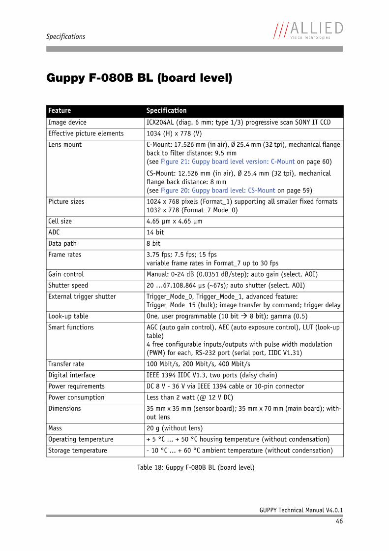
Guppy F-080B BL (board level)
Feature Specification
Image device ICX204AL (diag. 6 mm; type 1/3) progressive scan SONY IT CCD
Effective picture elements 1034 (H) x 778 (V)
Lens mount C-Mount: 17.526 mm (in air), Ø 25.4 mm (32 tpi), mechanical flange back to filter distance: 9.5 mm(see Figure 21: Guppy board level version: C-Mount on page 60)
CS-Mount: 12.526 mm (in air), Ø 25.4 mm (32 tpi), mechanical flange back distance: 8 mm(see Figure 20: Guppy board level: CS-Mount on page 59)
Picture sizes 1024 x 768 pixels (Format_1) supporting all smaller fixed formats1032 x 778 (Format_7 Mode_0)
Cell size 4.65 µm x 4.65 µm
ADC 14 bit
Data path 8 bit
Frame rates 3.75 fps; 7.5 fps; 15 fpsvariable frame rates in Format_7 up to 30 fps
Gain control Manual: 0-24 dB (0.0351 dB/step); auto gain (select. AOI)
Shutter speed 20 …67.108.864 µs (~67s); auto shutter (select. AOI)
External trigger shutter Trigger_Mode_0, Trigger_Mode_1, advanced feature: Trigger_Mode_15 (bulk); image transfer by command; trigger delay
Look-up table One, user programmable (10 bit 8 bit); gamma (0.5)
Smart functions AGC (auto gain control), AEC (auto exposure control), LUT (look-up table)4 free configurable inputs/outputs with pulse width modulation (PWM) for each, RS-232 port (serial port, IIDC V1.31)
Transfer rate 100 Mbit/s, 200 Mbit/s, 400 Mbit/s
Digital interface IEEE 1394 IIDC V1.3, two ports (daisy chain)
Power requirements DC 8 V - 36 V via IEEE 1394 cable or 10-pin connector
Power consumption Less than 2 watt (@ 12 V DC)
Dimensions 35 mm x 35 mm (sensor board); 35 mm x 70 mm (main board); with-out lens
Mass 20 g (without lens)
Operating temperature + 5 °C ... + 50 °C housing temperature (without condensation)
Storage temperature - 10 °C ... + 60 °C ambient temperature (without condensation)
Table 18: Guppy F-080B BL (board level)
Specifications
GUPPY Technical Manual V4.0.1
47
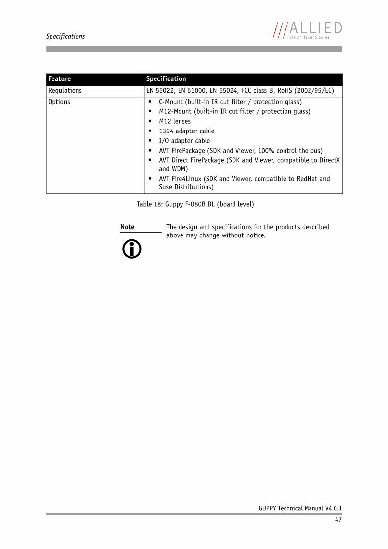
Regulations EN 55022, EN 61000, EN 55024, FCC class B, RoHS (2002/95/EC)
Options • C-Mount (built-in IR cut filter / protection glass)• M12-Mount (built-in IR cut filter / protection glass)• M12 lenses• 1394 adapter cable• I/O adapter cable• AVT FirePackage (SDK and Viewer, 100% control the bus)• AVT Direct FirePackage (SDK and Viewer, compatible to DirectX
and WDM)• AVT Fire4Linux (SDK and Viewer, compatible to RedHat and
Suse Distributions)
Note The design and specifications for the products described above may change without notice.
Feature Specification
Table 18: Guppy F-080B BL (board level)
Specifications
GUPPY Technical Manual V4.0.1
48
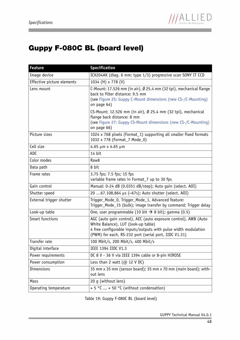
Guppy F-080C BL (board level)
Feature Specification
Image device ICX204AK (diag. 6 mm; type 1/3) progressive scan SONY IT CCD
Effective picture elements 1034 (H) x 778 (V)
Lens mount C-Mount: 17.526 mm (in air), Ø 25.4 mm (32 tpi), mechanical flange back to filter distance: 9.5 mm(see Figure 25: Guppy C-Mount dimensions (new CS-/C-Mounting) on page 64)
CS-Mount: 12.526 mm (in air), Ø 25.4 mm (32 tpi), mechanical flange back distance: 8 mm(see Figure 27: Guppy CS-Mount dimensions (new CS-/C-Mounting) on page 66)
Picture sizes 1024 x 768 pixels (Format_1) supporting all smaller fixed formats1032 x 778 (Format_7 Mode_0)
Cell size 4.65 µm x 4.65 µm
ADC 14 bit
Color modes Raw8
Data path 8 bit
Frame rates 3.75 fps; 7.5 fps; 15 fpsvariable frame rates in Format_7 up to 30 fps
Gain control Manual: 0-24 dB (0.0351 dB/step); Auto gain (select. AOI)
Shutter speed 20 …67.108.864 µs (~67s); Auto shutter (select. AOI)
External trigger shutter Trigger_Mode_0, Trigger_Mode_1, Advanced feature: Trigger_Mode_15 (bulk); image transfer by command; Trigger delay
Look-up table One, user programmable (10 bit 8 bit); gamma (0.5)
Smart functions AGC (auto gain control), AEC (auto exposure control), AWB (Auto White Balance), LUT (look-up table)4 free configurable inputs/outputs with pulse width modulation (PWM) for each, RS-232 port (serial port, IIDC V1.31)
Transfer rate 100 Mbit/s, 200 Mbit/s, 400 Mbit/s
Digital interface IEEE 1394 IIDC V1.3
Power requirements DC 8 V - 36 V via IEEE 1394 cable or 8-pin HIROSE
Power consumption Less than 2 watt (@ 12 V DC)
Dimensions 35 mm x 35 mm (sensor board); 35 mm x 70 mm (main board); with-out lens
Mass 20 g (without lens)
Operating temperature + 5 °C ... + 50 °C (without condensation)
Table 19: Guppy F-080C BL (board level)

Specifications
GUPPY Technical Manual V4.0.1
49
Storage temperature - 10 °C ... + 60 °C ambient temperature (without condensation)
Regulations EN 55022, EN 61000, EN 55024, FCC class B, RoHS (2002/95/EC)
Options • C-Mount (built-in IR cut filter / protection glass)• M12-Mount (built-in IR cut filter / protection glass)• M12 lenses• 1394 adapter cable• I/O adapter cable• AVT FirePackage (SDK and Viewer, 100% control the bus)• AVT Direct FirePackage (SDK and Viewer, compatible to DirectX
and WDM)• AVT Fire4Linux (SDK and Viewer, compatible to RedHat and
Suse Distributions)
Note The design and specifications for the products described above may change without notice.
Feature Specification
Table 19: Guppy F-080C BL (board level)
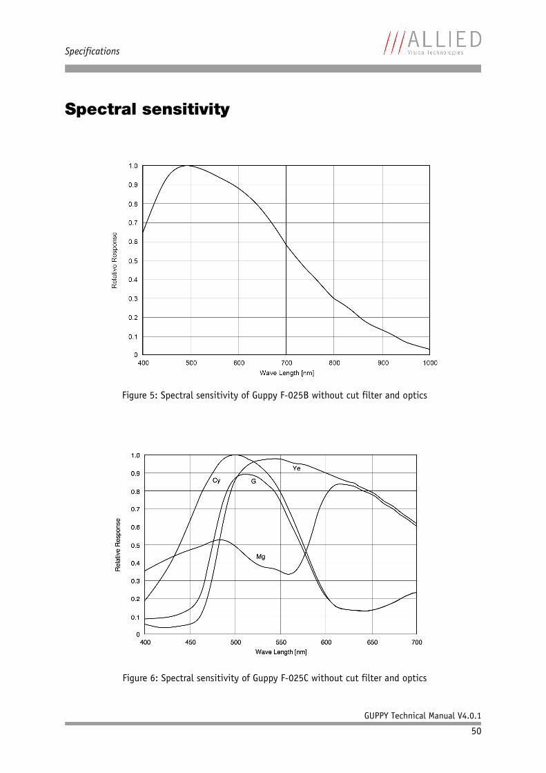
Specifications
GUPPY Technical Manual V4.0.1
50
Spectral sensitivity
Figure 5: Spectral sensitivity of Guppy F-025B without cut filter and optics
Figure 6: Spectral sensitivity of Guppy F-025C without cut filter and optics
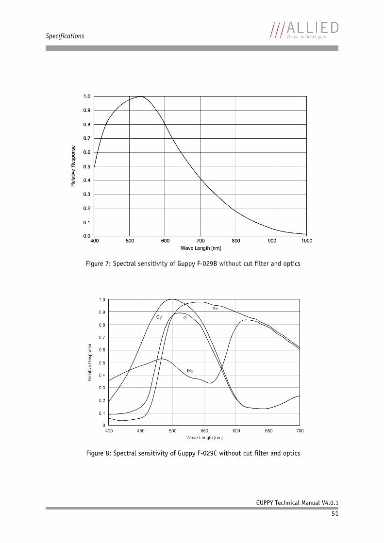
Specifications
GUPPY Technical Manual V4.0.1
51
Figure 7: Spectral sensitivity of Guppy F-029B without cut filter and optics
Figure 8: Spectral sensitivity of Guppy F-029C without cut filter and optics
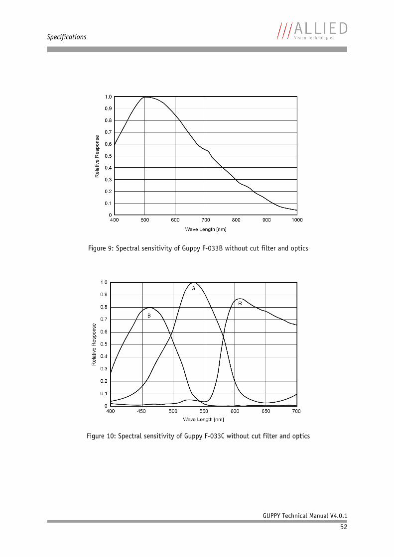
Specifications
GUPPY Technical Manual V4.0.1
52
Figure 9: Spectral sensitivity of Guppy F-033B without cut filter and optics
Figure 10: Spectral sensitivity of Guppy F-033C without cut filter and optics
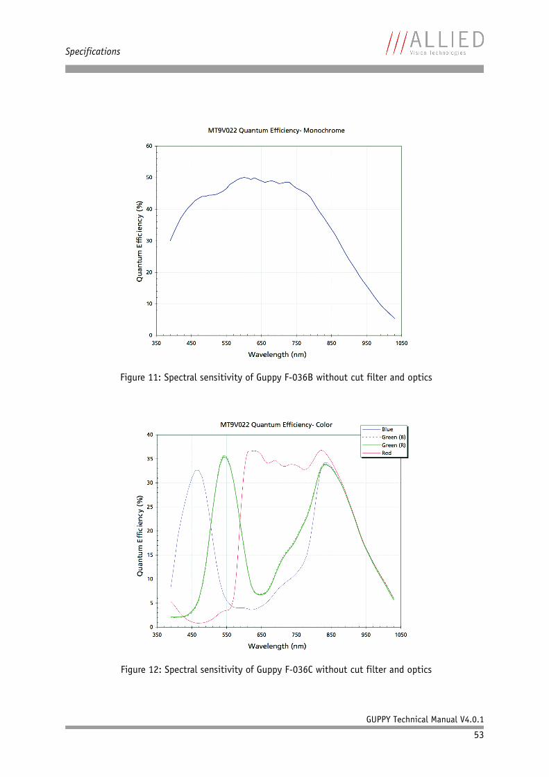
Specifications
GUPPY Technical Manual V4.0.1
53
Figure 11: Spectral sensitivity of Guppy F-036B without cut filter and optics
Figure 12: Spectral sensitivity of Guppy F-036C without cut filter and optics
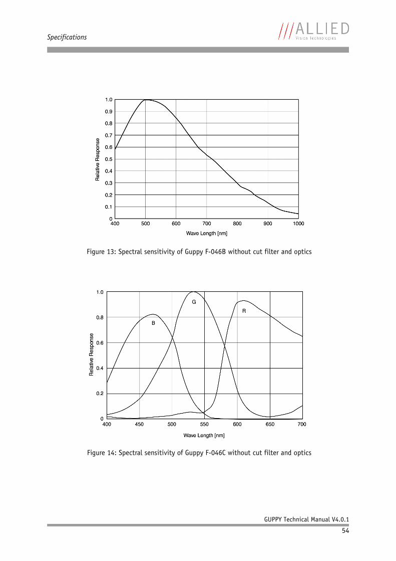
Specifications
GUPPY Technical Manual V4.0.1
54
Figure 13: Spectral sensitivity of Guppy F-046B without cut filter and optics
Figure 14: Spectral sensitivity of Guppy F-046C without cut filter and optics
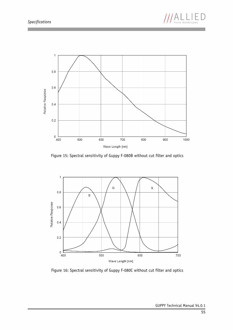
Specifications
GUPPY Technical Manual V4.0.1
55
Figure 15: Spectral sensitivity of Guppy F-080B without cut filter and optics
Figure 16: Spectral sensitivity of Guppy F-080C without cut filter and optics
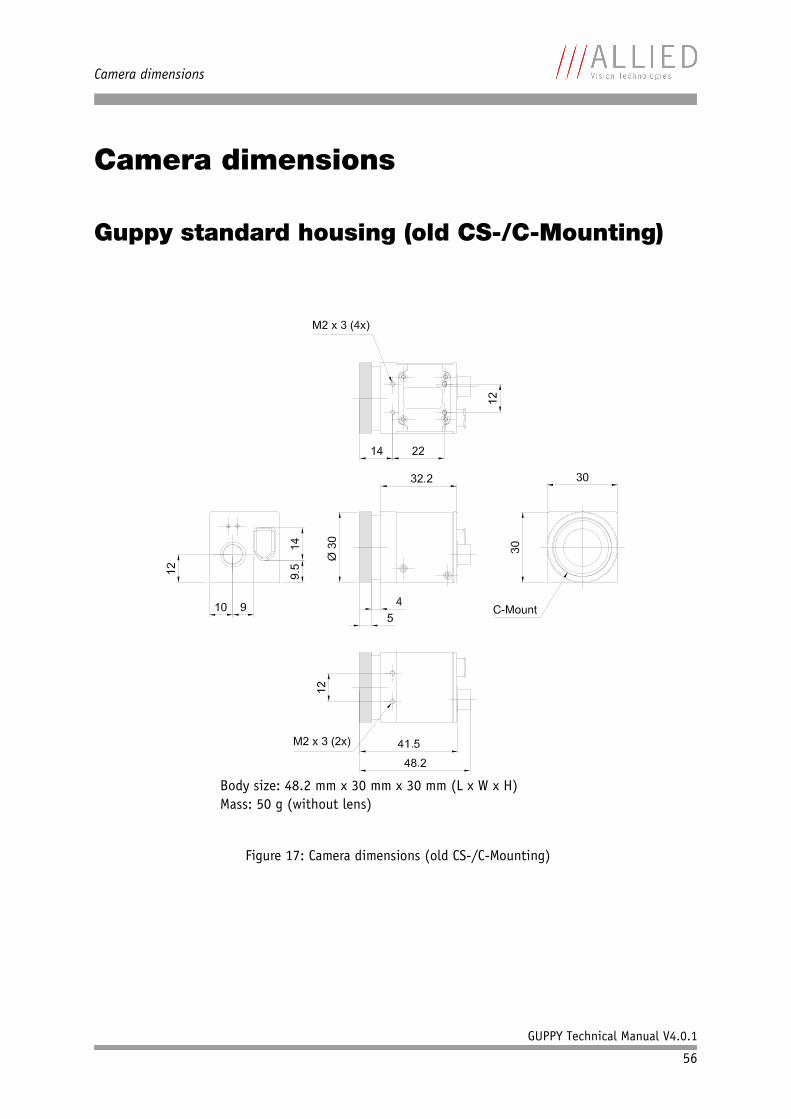
Camera dimensions
GUPPY Technical Manual V4.0.1
56
Camera dimensions
Guppy standard housing (old CS-/C-Mounting)
Figure 17: Camera dimensions (old CS-/C-Mounting)
Body size: 48.2 mm x 30 mm x 30 mm (L x W x H)Mass: 50 g (without lens)
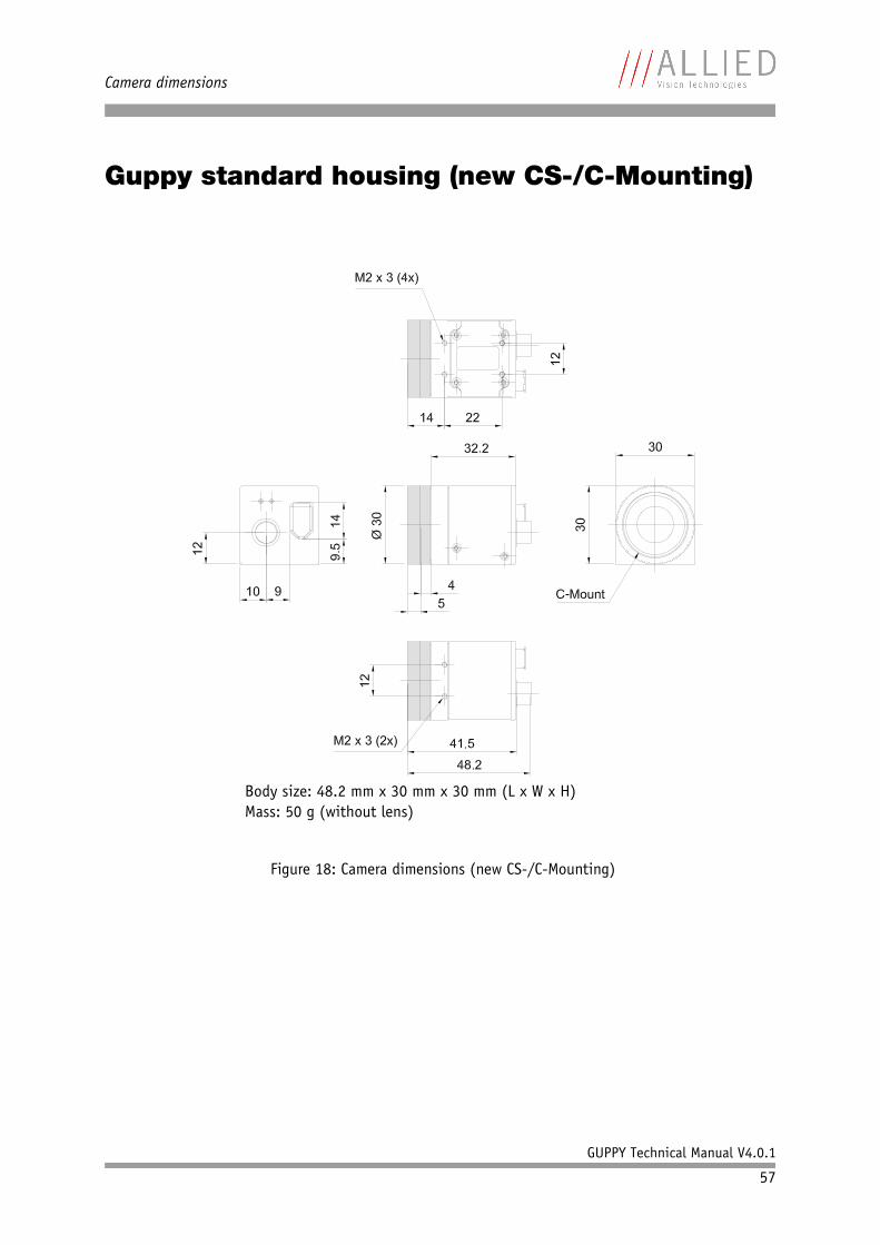
Camera dimensions
GUPPY Technical Manual V4.0.1
57
Guppy standard housing (new CS-/C-Mounting)
Figure 18: Camera dimensions (new CS-/C-Mounting)
Body size: 48.2 mm x 30 mm x 30 mm (L x W x H)Mass: 50 g (without lens)
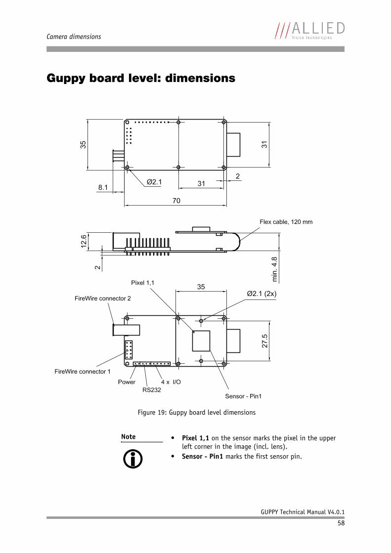
Camera dimensions
GUPPY Technical Manual V4.0.1
58
Guppy board level: dimensions
Figure 19: Guppy board level dimensions
Note • Pixel 1,1 on the sensor marks the pixel in the upper left corner in the image (incl. lens).
• Sensor - Pin1 marks the first sensor pin.
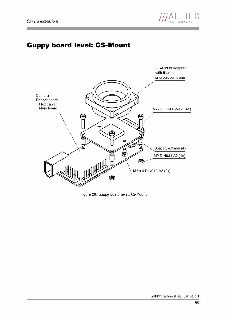
Camera dimensions
GUPPY Technical Manual V4.0.1
59
Guppy board level: CS-Mount
Figure 20: Guppy board level: CS-Mount
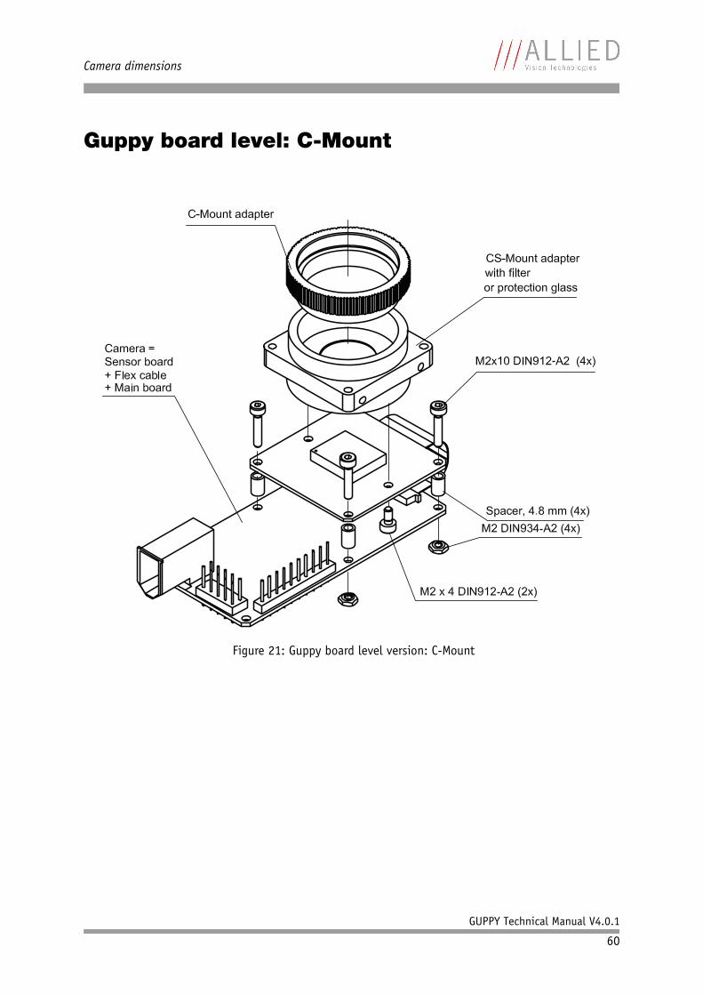
Camera dimensions
GUPPY Technical Manual V4.0.1
60
Guppy board level: C-Mount
Figure 21: Guppy board level version: C-Mount
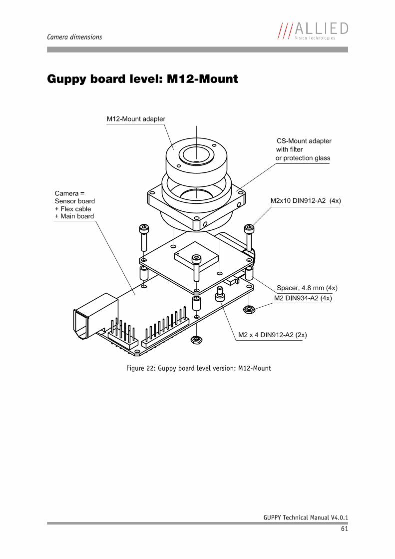
Camera dimensions
GUPPY Technical Manual V4.0.1
61
Guppy board level: M12-Mount
Figure 22: Guppy board level version: M12-Mount
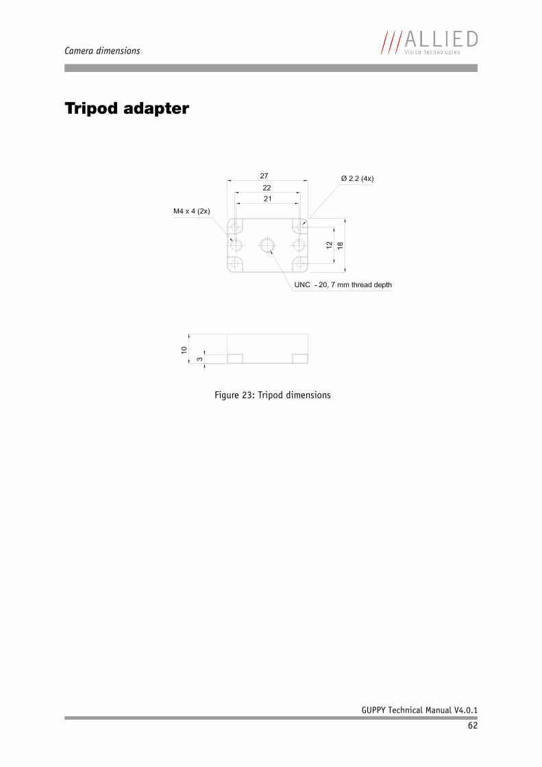
Camera dimensions
GUPPY Technical Manual V4.0.1
62
Tripod adapter
Figure 23: Tripod dimensions
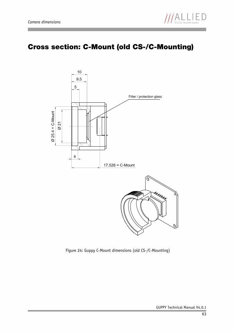
Camera dimensions
GUPPY Technical Manual V4.0.1
63
Cross section: C-Mount (old CS-/C-Mounting)
Figure 24: Guppy C-Mount dimensions (old CS-/C-Mounting)
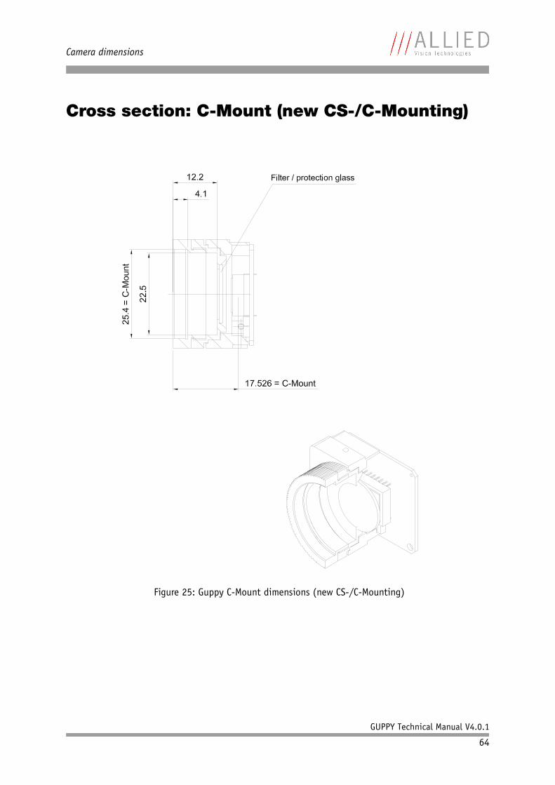
Camera dimensions
GUPPY Technical Manual V4.0.1
64
Cross section: C-Mount (new CS-/C-Mounting)
Figure 25: Guppy C-Mount dimensions (new CS-/C-Mounting)
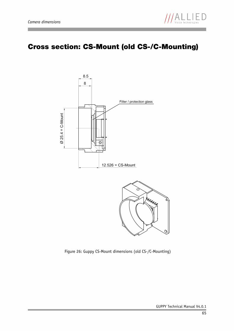
Camera dimensions
GUPPY Technical Manual V4.0.1
65
Cross section: CS-Mount (old CS-/C-Mounting)
Figure 26: Guppy CS-Mount dimensions (old CS-/C-Mounting)
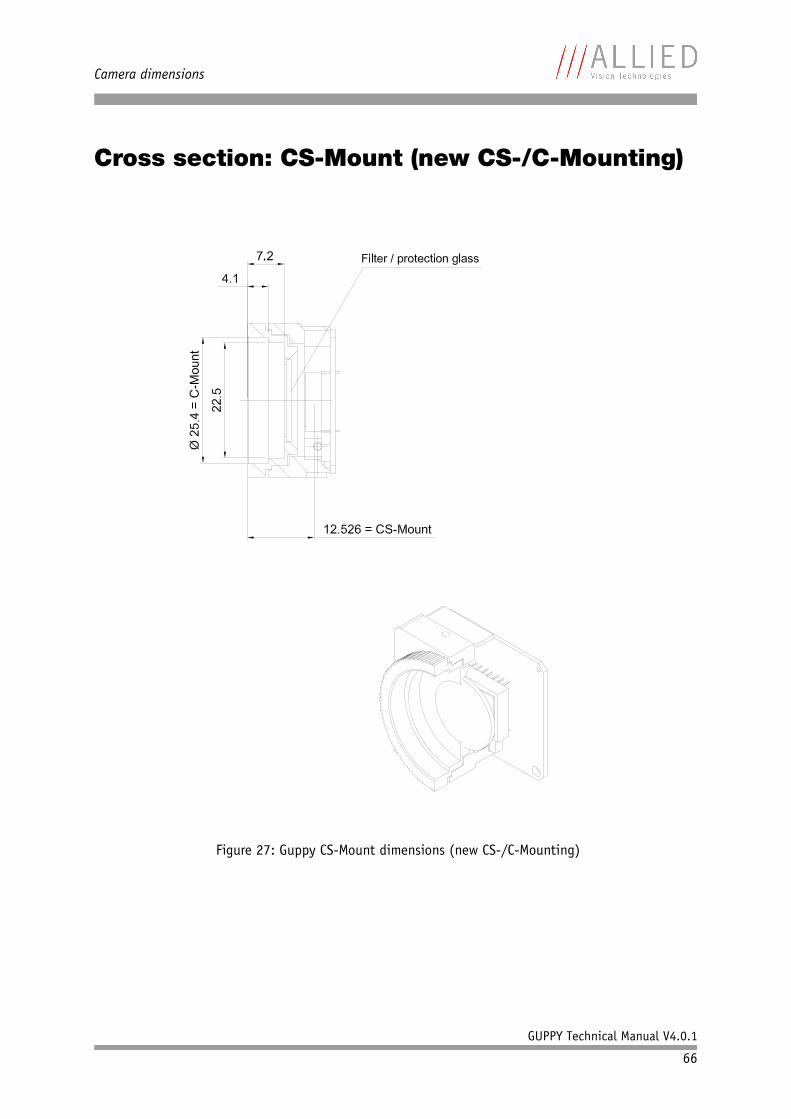
Camera dimensions
GUPPY Technical Manual V4.0.1
66
Cross section: CS-Mount (new CS-/C-Mounting)
Figure 27: Guppy CS-Mount dimensions (new CS-/C-Mounting)
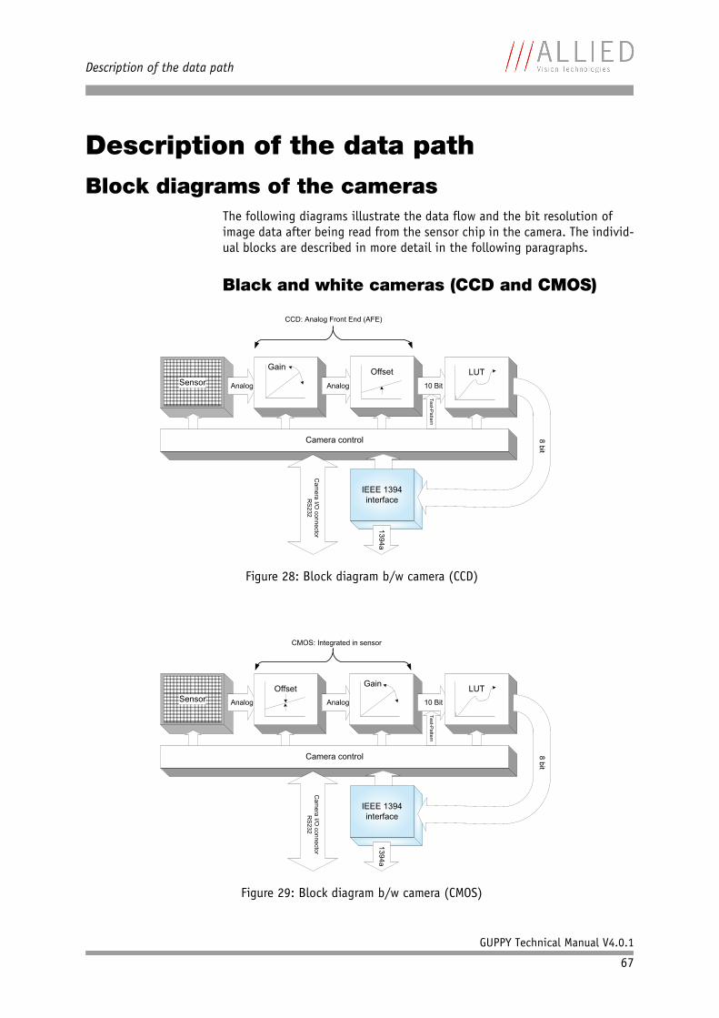
Description of the data path
GUPPY Technical Manual V4.0.1
67
Description of the data pathBlock diagrams of the cameras
The following diagrams illustrate the data flow and the bit resolution of image data after being read from the sensor chip in the camera. The individ-ual blocks are described in more detail in the following paragraphs.
Black and white cameras (CCD and CMOS)
Figure 28: Block diagram b/w camera (CCD)
Figure 29: Block diagram b/w camera (CMOS)
Sensor
Test-P
atte
rn
IEEE 1394
interface
13
94
a
8 b
it
Analog
Gain
CCD: Analog Front End (AFE)
Analog
Offset
10 Bit
LUT
Camera control
Cam
era
I/O c
onnecto
r
RS
232
Sensor
Test-P
atte
rn
IEEE 1394
interface
13
94
a
8 b
it
Analog
Offset
Analog
Gain
10 Bit
LUT
Camera control
Cam
era
I/O c
onnecto
r
RS
232
CMOS: Integrated in sensor
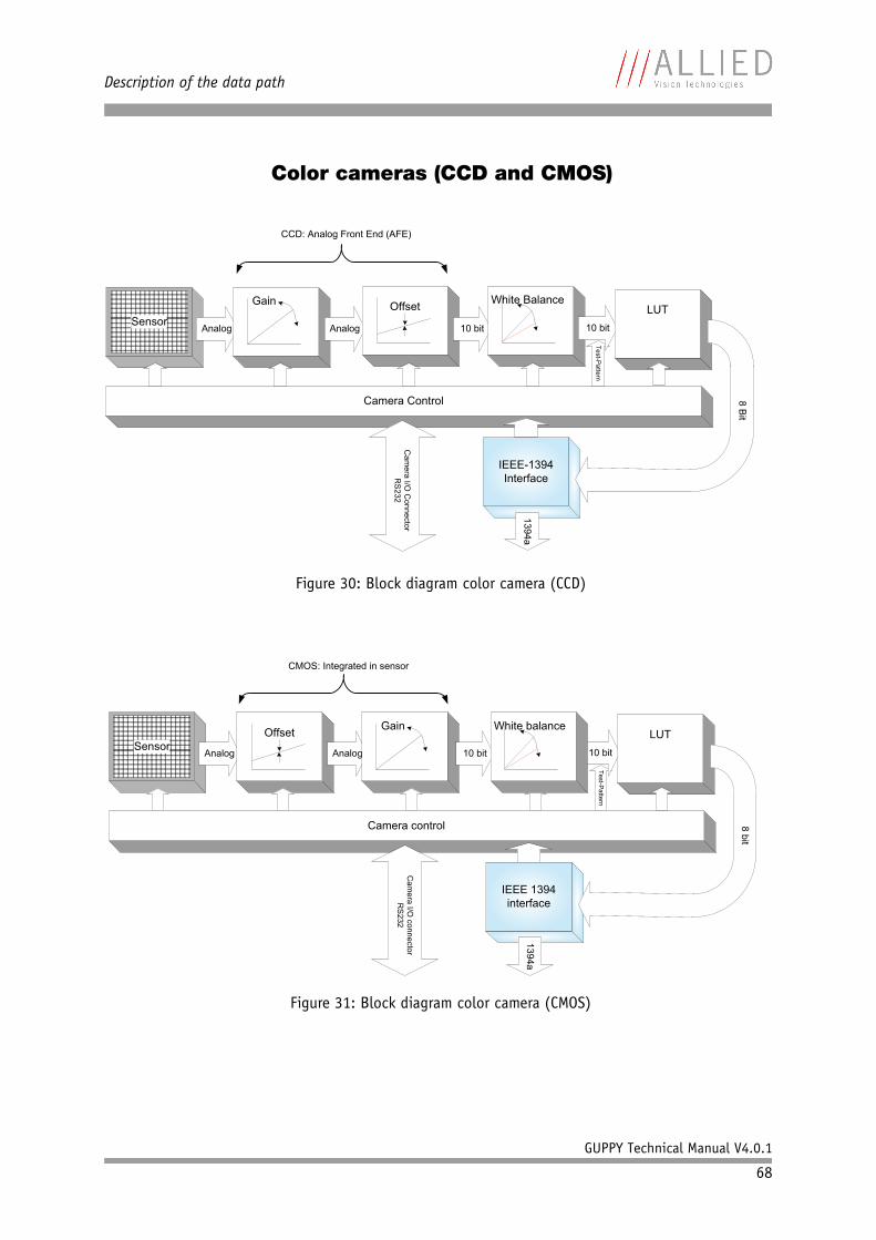
Description of the data path
GUPPY Technical Manual V4.0.1
68
Color cameras (CCD and CMOS)
Figure 30: Block diagram color camera (CCD)
Figure 31: Block diagram color camera (CMOS)
Camera Control
CCD: Analog Front End (AFE)
Test-P
atte
rn
IEEE-1394
Interface
1394a
Cam
era
I/O C
onnecto
r
RS
232
SensorAnalog
Gain
Analog
Offset
10 bit
White Balance
10 bit
LUT
8 B
it
Camera control
CMOS: Integrated in sensor
Te
st-P
atte
rn
IEEE 1394
interface
1394a
Cam
era
I/O c
onnecto
r
RS
232
SensorAnalog
Offset
Analog
Gain
10 bit 10 bit
LUT
8 b
it
White balance
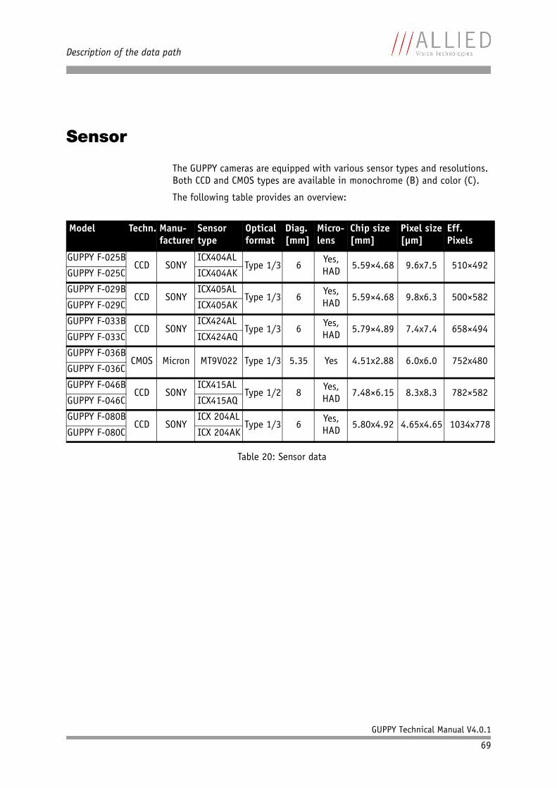
Description of the data path
GUPPY Technical Manual V4.0.1
69
Sensor
The GUPPY cameras are equipped with various sensor types and resolutions. Both CCD and CMOS types are available in monochrome (B) and color (C).
The following table provides an overview:
Model Techn. Manu-facturer
Sensor type
Optical format
Diag. [mm]
Micro-lens
Chip size[mm]
Pixel size[µm]
Eff.Pixels
GUPPY F-025BCCD SONY
ICX404ALType 1/3 6
Yes, HAD
5.59×4.68 9.6x7.5 510×492GUPPY F-025C ICX404AK
GUPPY F-029BCCD SONY
ICX405ALType 1/3 6
Yes, HAD
5.59×4.68 9.8x6.3 500×582GUPPY F-029C ICX405AK
GUPPY F-033BCCD SONY
ICX424ALType 1/3 6
Yes, HAD
5.79×4.89 7.4x7.4 658×494GUPPY F-033C ICX424AQ
GUPPY F-036BCMOS Micron MT9V022 Type 1/3 5.35 Yes 4.51x2.88 6.0x6.0 752x480
GUPPY F-036C
GUPPY F-046BCCD SONY
ICX415ALType 1/2 8
Yes, HAD
7.48×6.15 8.3x8.3 782×582GUPPY F-046C ICX415AQ
GUPPY F-080BCCD SONY
ICX 204ALType 1/3 6
Yes, HAD
5.80x4.92 4.65x4.65 1034x778GUPPY F-080C ICX 204AK
Table 20: Sensor data
Description of the data path
GUPPY Technical Manual V4.0.1
70
Horizontal and vertical mirror function(only Guppy F-036)
The Guppy F-036 CMOS cameras are equipped with a horizontal and verticaql mirror function, which is built directly into the sensor. The mirror is centered to the actual FOV center and can be combined with all image manipulation functions, like binning.
This function is especially useful when the camera is looking at objects with the help of a mirror or in certain microscopy applications.
To configure this feature in an advanced register: See Table 106: Mirror con-trol register on page 204.
Note When using the mirror function, the starting color is main-tained.
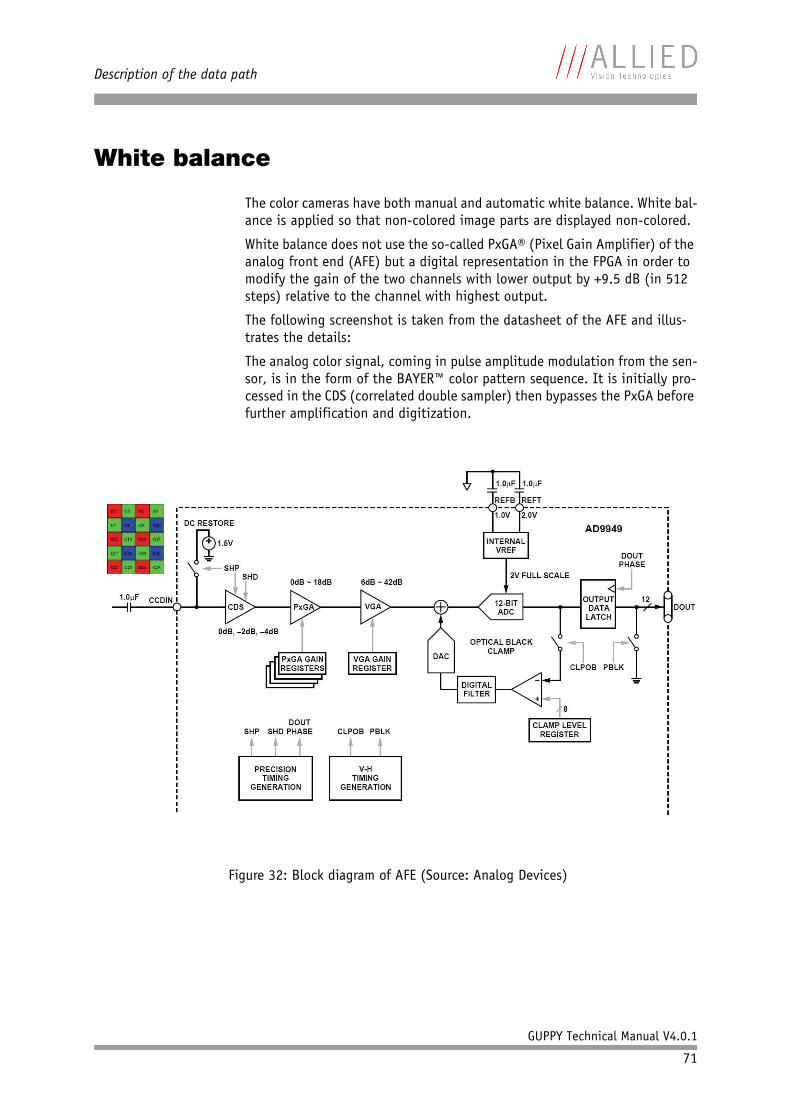
Description of the data path
GUPPY Technical Manual V4.0.1
71
White balance
The color cameras have both manual and automatic white balance. White bal-ance is applied so that non-colored image parts are displayed non-colored.
White balance does not use the so-called PxGA® (Pixel Gain Amplifier) of the analog front end (AFE) but a digital representation in the FPGA in order to modify the gain of the two channels with lower output by +9.5 dB (in 512 steps) relative to the channel with highest output.
The following screenshot is taken from the datasheet of the AFE and illus-trates the details:
The analog color signal, coming in pulse amplitude modulation from the sen-sor, is in the form of the BAYER™ color pattern sequence. It is initially pro-cessed in the CDS (correlated double sampler) then bypasses the PxGA before further amplification and digitization.
Figure 32: Block diagram of AFE (Source: Analog Devices)
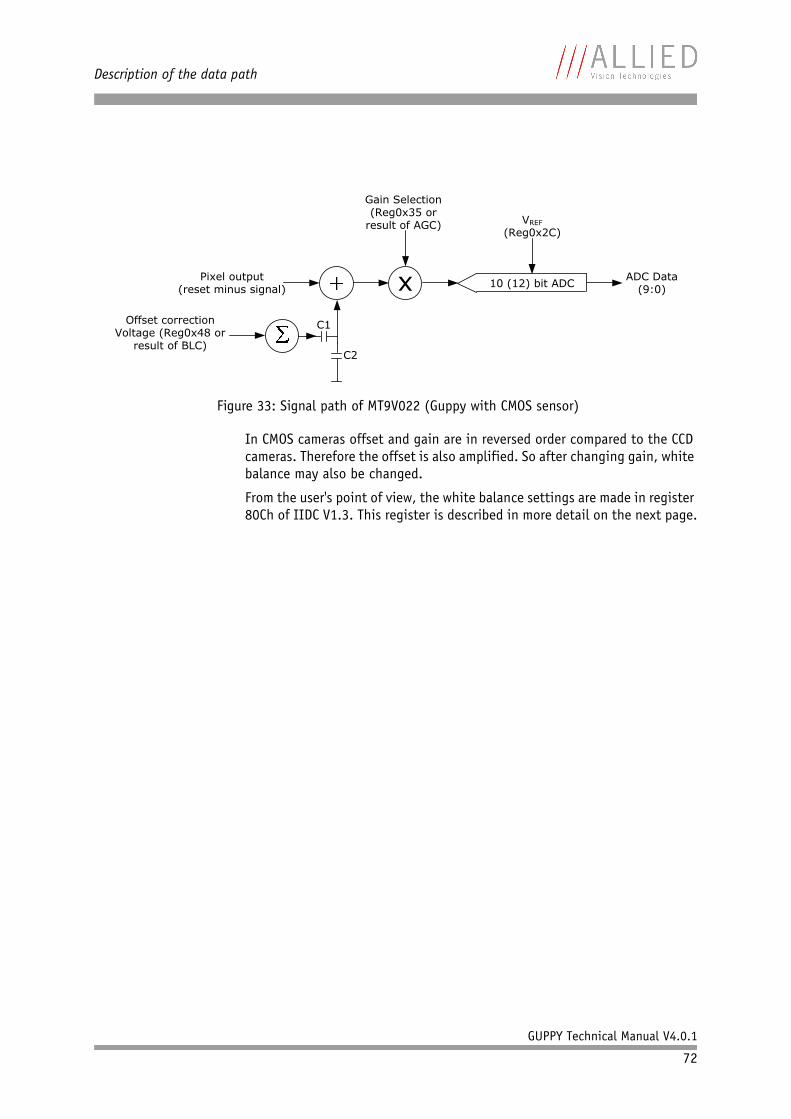
Description of the data path
GUPPY Technical Manual V4.0.1
72
In CMOS cameras offset and gain are in reversed order compared to the CCD cameras. Therefore the offset is also amplified. So after changing gain, white balance may also be changed.
From the user's point of view, the white balance settings are made in register 80Ch of IIDC V1.3. This register is described in more detail on the next page.
Figure 33: Signal path of MT9V022 (Guppy with CMOS sensor)
xPixel output(reset minus signal)
Offset correctionVoltage (Reg0x48 or
result of BLC)
VREF
(Reg0x2C)
Gain Selection(Reg0x35 or
result of AGC)
ADC Data (9:0)
C2
C1
10 (12) bit ADC
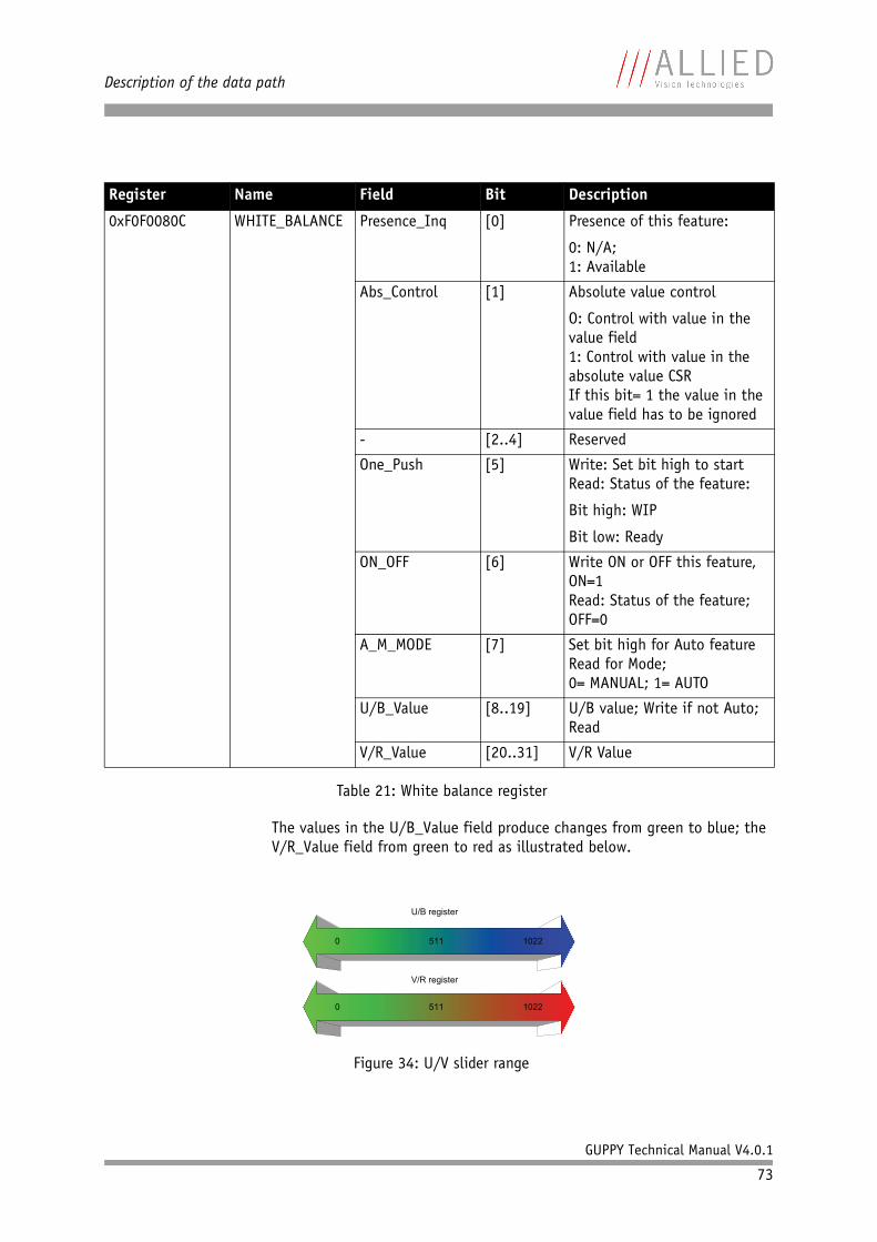
Description of the data path
GUPPY Technical Manual V4.0.1
73
The values in the U/B_Value field produce changes from green to blue; the V/R_Value field from green to red as illustrated below.
Register Name Field Bit Description
0xF0F0080C WHITE_BALANCE Presence_Inq [0] Presence of this feature:
0: N/A;1: Available
Abs_Control [1] Absolute value control
O: Control with value in the value field1: Control with value in the absolute value CSRIf this bit= 1 the value in the value field has to be ignored
- [2..4] Reserved
One_Push [5] Write: Set bit high to start Read: Status of the feature:
Bit high: WIP
Bit low: Ready
ON_OFF [6] Write ON or OFF this feature, ON=1Read: Status of the feature; OFF=0
A_M_MODE [7] Set bit high for Auto featureRead for Mode;0= MANUAL; 1= AUTO
U/B_Value [8..19] U/B value; Write if not Auto; Read
V/R_Value [20..31] V/R Value
Table 21: White balance register
Figure 34: U/V slider range
Description of the data path
GUPPY Technical Manual V4.0.1
74
One-push automatic white balanceIt is activated by setting the one-push bit in the WHITE_BALANCE register (see Chapter Status and control register for feature on page 181). The camera automatically generates frames, based on the current settings of all registers (GAIN, OFFSET, SHUTTER, etc.).
For white balance, in total eight frames are processed and a grid of at least 65536 samples is equally spread over the whole image area. The R-G-B com-ponent values of the samples are added and are used as actual values for both the one-push and the automatic white balance.
This feature uses the assumption that the R-G-B component sums of the sam-ples are equal; i.e., it assumes that the average of the sampled grid pixels is to be monochrome.
If the image capture is active (e.g. IsoEnable set in register 614h), the frames used by the camera for white balance are also output on the 1394 bus. Any previously active image capture is restarted after the completion of white balance.
Automatic white balance can also be enabled by using an external trigger. However, if there is a pause of >10 seconds between capturing individual frames this process is aborted.
The following flow diagram illustrates the automatic white balance sequence.
Note The following ancillary conditions should be observed for suc-cessful white balance:
• There are no stringent or special requirements on the image content, it requires only the presence of mono-chrome pixels in the image.
• Automatic white balance can be started both during active image capture and when the camera is in idle state.
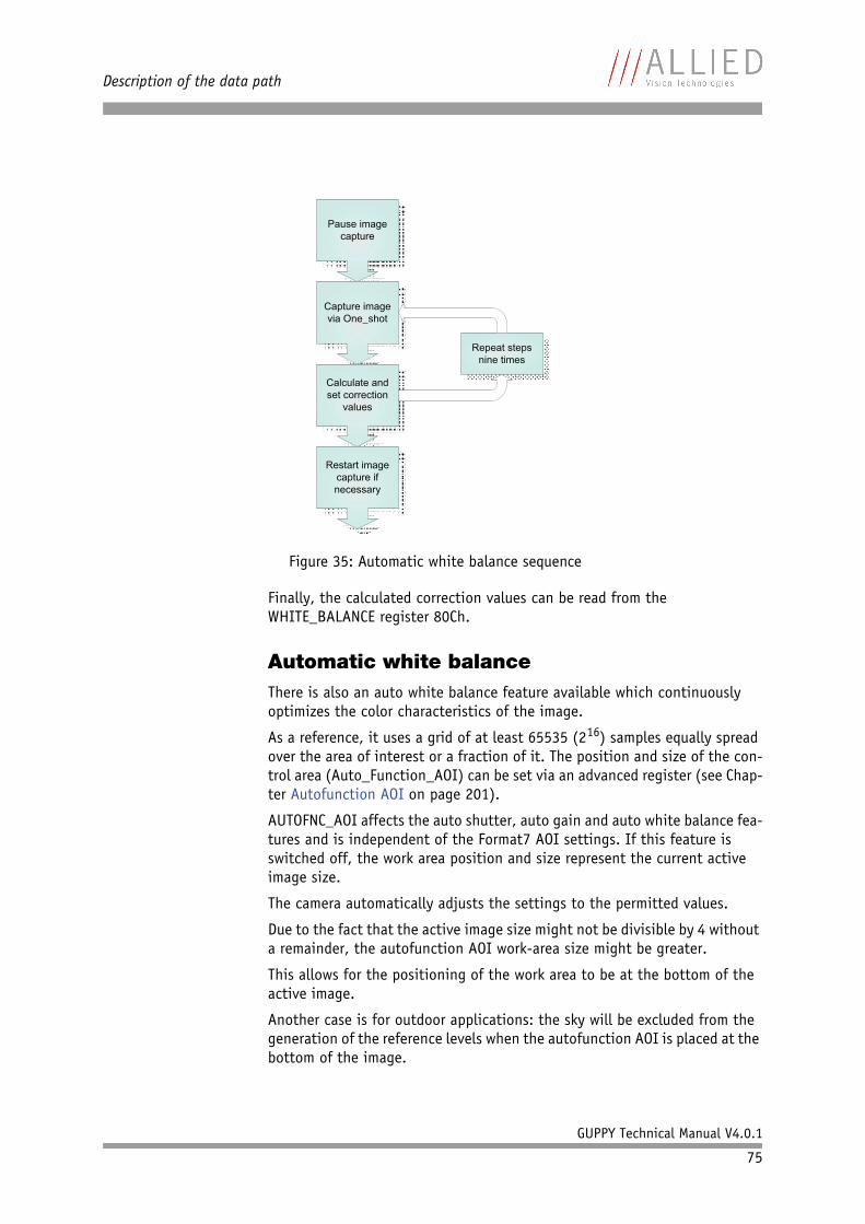
Description of the data path
GUPPY Technical Manual V4.0.1
75
Finally, the calculated correction values can be read from the WHITE_BALANCE register 80Ch.
Automatic white balanceThere is also an auto white balance feature available which continuously optimizes the color characteristics of the image.
As a reference, it uses a grid of at least 65535 (216) samples equally spread over the area of interest or a fraction of it. The position and size of the con-trol area (Auto_Function_AOI) can be set via an advanced register (see Chap-ter Autofunction AOI on page 201).
AUTOFNC_AOI affects the auto shutter, auto gain and auto white balance fea-tures and is independent of the Format7 AOI settings. If this feature is switched off, the work area position and size represent the current active image size.
The camera automatically adjusts the settings to the permitted values.
Due to the fact that the active image size might not be divisible by 4 without a remainder, the autofunction AOI work-area size might be greater.
This allows for the positioning of the work area to be at the bottom of the active image.
Another case is for outdoor applications: the sky will be excluded from the generation of the reference levels when the autofunction AOI is placed at the bottom of the image.
Figure 35: Automatic white balance sequence
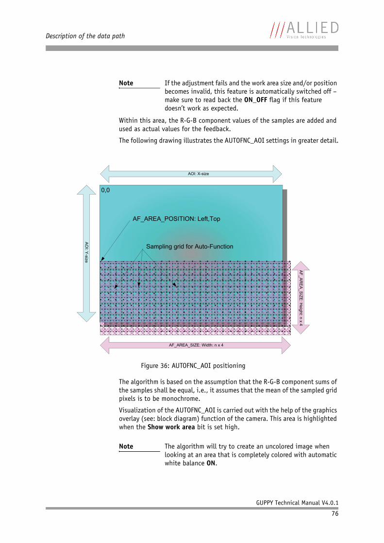
Description of the data path
GUPPY Technical Manual V4.0.1
76
Within this area, the R-G-B component values of the samples are added and used as actual values for the feedback.
The following drawing illustrates the AUTOFNC_AOI settings in greater detail.
The algorithm is based on the assumption that the R-G-B component sums of the samples shall be equal, i.e., it assumes that the mean of the sampled grid pixels is to be monochrome.
Visualization of the AUTOFNC_AOI is carried out with the help of the graphics overlay (see: block diagram) function of the camera. This area is highlighted when the Show work area bit is set high.
Note If the adjustment fails and the work area size and/or position becomes invalid, this feature is automatically switched off – make sure to read back the ON_OFF flag if this feature doesn’t work as expected.
Figure 36: AUTOFNC_AOI positioning
Note The algorithm will try to create an uncolored image when looking at an area that is completely colored with automatic white balance ON.
AO
I: Y-s
ize
AOI: X-size
AF_AREA_SIZE: Width: n x 4
AF
_A
RE
A_S
IZE
: He
ight: n
x 4
0,0
AF_AREA_POSITION: Left,Top
Sampling grid for Auto-Function
Description of the data path
GUPPY Technical Manual V4.0.1
77
Manual gain
As shown in Figure 32: Block diagram of AFE (Source: Analog Devices) on page 71 and Figure 33: Signal path of MT9V022 (Guppy with CMOS sensor) on page 72, all cameras are equipped with a gain setting, allowing the gain to be manually adjusted on the fly by means of a simple command register write.
The following ranges can be used when manually setting the gain for the ana-log video signal:
The increment length for CCD models is ~0.0354 dB/step.
The increment length for the CMOS model is:
0..15: ~0.2 dB/step (1 step = 1 LSB)
16..48: ~0.28 dB/step (1 step = 2 LSB)
Auto gain
In combination with auto white balance, all CCD and CMOS models are equipped with auto gain feature.
When enabled auto gain adjusts the gain within the default gain limits or within the limits set in advanced register F1000370h in order to reach the brightness set in auto exposure register as reference.
Increasing the auto exposure value (aka target grey value) increases the aver-age brightness in the image and vice versa.
The applied algorithm uses a proportional plus integral controller (PI control-ler) to achieve minimum delay with zero overshot.
The following table shows both the gain and auto exposure CSR.
Type Range Range in dB
CCD cameras 0 ... 680 0 … 24 dB
CMOS camera 1 … 48 0 … 12 dB
Table 22: Manual gain range of the various GUPPY types
Note • Setting the gain does not change the offset (black value) for CCD models.
• A higher gain also produces greater image noise. This reduces image quality. For this reason, try first to increase the brightness, using the aperture of the cam-era optics and/or longer shutter settings.
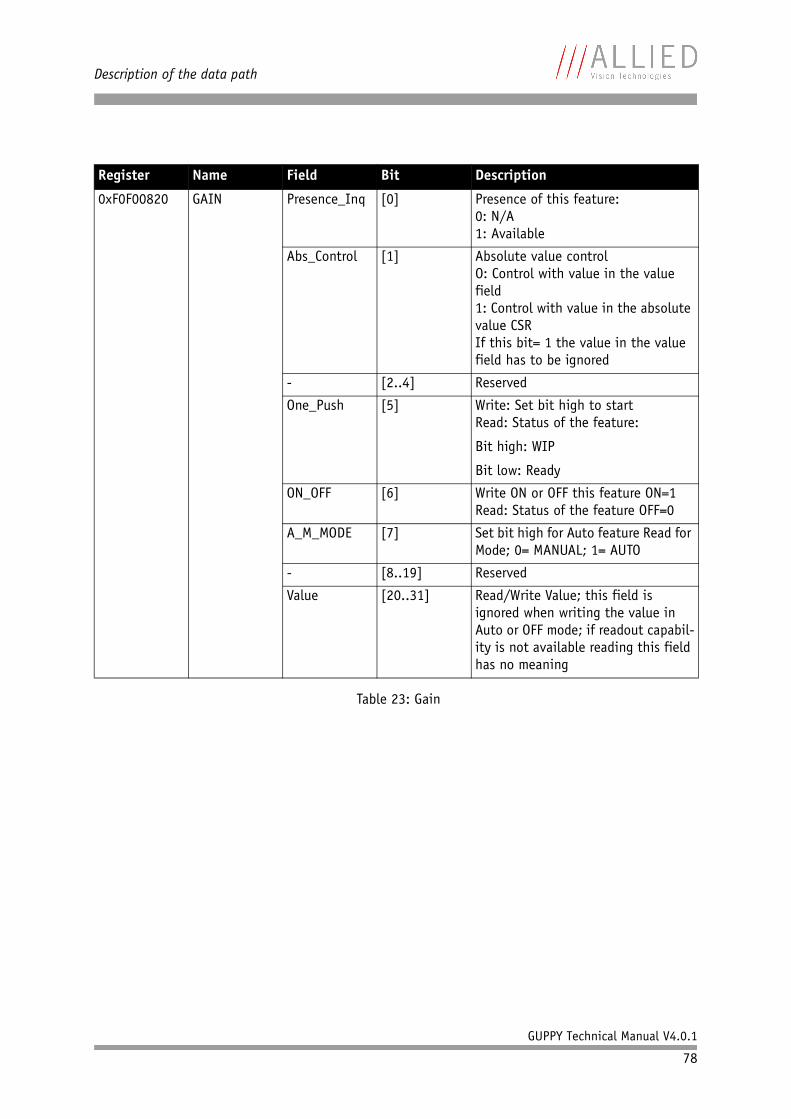
Description of the data path
GUPPY Technical Manual V4.0.1
78
Register Name Field Bit Description
0xF0F00820 GAIN Presence_Inq [0] Presence of this feature:0: N/A1: Available
Abs_Control [1] Absolute value controlO: Control with value in the value field1: Control with value in the absolute value CSRIf this bit= 1 the value in the value field has to be ignored
- [2..4] Reserved
One_Push [5] Write: Set bit high to startRead: Status of the feature:
Bit high: WIP
Bit low: Ready
ON_OFF [6] Write ON or OFF this feature ON=1Read: Status of the feature OFF=0
A_M_MODE [7] Set bit high for Auto feature Read for Mode; 0= MANUAL; 1= AUTO
- [8..19] Reserved
Value [20..31] Read/Write Value; this field is ignored when writing the value in Auto or OFF mode; if readout capabil-ity is not available reading this field has no meaning
Table 23: Gain
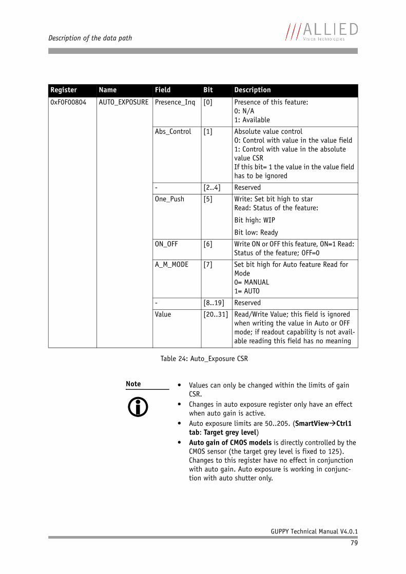
Description of the data path
GUPPY Technical Manual V4.0.1
79
Register Name Field Bit Description
0xF0F00804 AUTO_EXPOSURE Presence_Inq [0] Presence of this feature:0: N/A1: Available
Abs_Control [1] Absolute value controlO: Control with value in the value field1: Control with value in the absolute value CSRIf this bit= 1 the value in the value field has to be ignored
- [2..4] Reserved
One_Push [5] Write: Set bit high to starRead: Status of the feature:
Bit high: WIP
Bit low: Ready
ON_OFF [6] Write ON or OFF this feature, ON=1 Read: Status of the feature; OFF=0
A_M_MODE [7] Set bit high for Auto feature Read for Mode0= MANUAL1= AUTO
- [8..19] Reserved
Value [20..31] Read/Write Value; this field is ignored when writing the value in Auto or OFF mode; if readout capability is not avail-able reading this field has no meaning
Table 24: Auto_Exposure CSR
Note • Values can only be changed within the limits of gain CSR.
• Changes in auto exposure register only have an effect when auto gain is active.
• Auto exposure limits are 50..205. (SmartView Ctrl1 tab: Target grey level)
• Auto gain of CMOS models is directly controlled by the CMOS sensor (the target grey level is fixed to 125). Changes to this register have no effect in conjunction with auto gain. Auto exposure is working in conjunc-tion with auto shutter only.
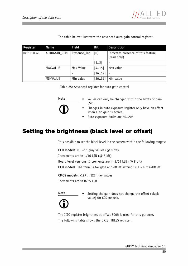
Description of the data path
GUPPY Technical Manual V4.0.1
80
The table below illustrates the advanced auto gain control register.
Setting the brightness (black level or offset)
It is possible to set the black level in the camera within the following ranges:
CCD models: 0...+16 gray values (@ 8 bit)
Increments are in 1/16 LSB (@ 8 bit)
Board level versions: Increments are in 1/64 LSB (@ 8 bit)
CCD models: The formula for gain and offset setting is: Y`= G x Y+Offset
CMOS models: -127 .. 127 gray values
Increments are in 8/25 LSB
The IIDC register brightness at offset 800h is used for this purpose.
The following table shows the BRIGHTNESS register.
Register Name Field Bit Description
0xF1000370 AUTOGAIN_CTRL Presence_Inq [0] Indicates presence of this feature(read only)
[1..3] -
MAXVALUE Max Value [4..15] Max value
- [16..19] -
MINVALUE Min value [20..31] Min value
Table 25: Advanced register for auto gain control
Note • Values can only be changed within the limits of gain CSR.
• Changes in auto exposure register only have an effect when auto gain is active.
• Auto exposure limits are 50..205.
Note • Setting the gain does not change the offset (black value) for CCD models.
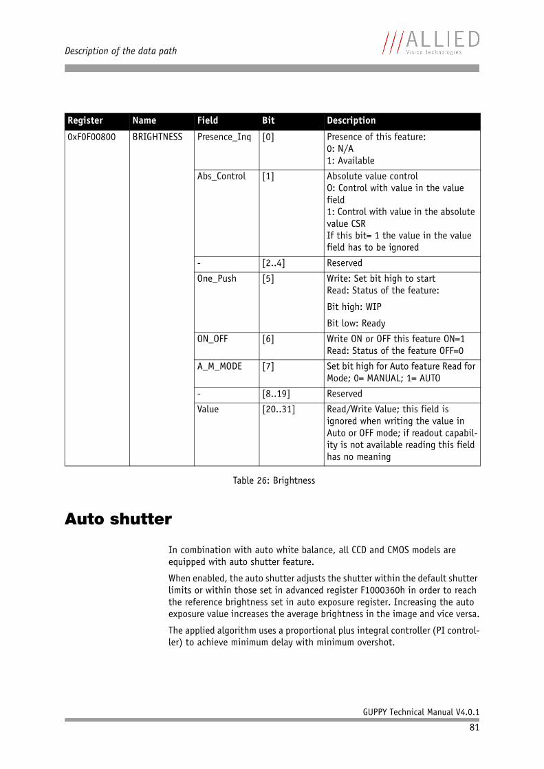
Description of the data path
GUPPY Technical Manual V4.0.1
81
Auto shutter
In combination with auto white balance, all CCD and CMOS models are equipped with auto shutter feature.
When enabled, the auto shutter adjusts the shutter within the default shutter limits or within those set in advanced register F1000360h in order to reach the reference brightness set in auto exposure register. Increasing the auto exposure value increases the average brightness in the image and vice versa.
The applied algorithm uses a proportional plus integral controller (PI control-ler) to achieve minimum delay with minimum overshot.
Register Name Field Bit Description
0xF0F00800 BRIGHTNESS Presence_Inq [0] Presence of this feature:0: N/A1: Available
Abs_Control [1] Absolute value controlO: Control with value in the value field1: Control with value in the absolute value CSRIf this bit= 1 the value in the value field has to be ignored
- [2..4] Reserved
One_Push [5] Write: Set bit high to startRead: Status of the feature:
Bit high: WIP
Bit low: Ready
ON_OFF [6] Write ON or OFF this feature ON=1Read: Status of the feature OFF=0
A_M_MODE [7] Set bit high for Auto feature Read for Mode; 0= MANUAL; 1= AUTO
- [8..19] Reserved
Value [20..31] Read/Write Value; this field is ignored when writing the value in Auto or OFF mode; if readout capabil-ity is not available reading this field has no meaning
Table 26: Brightness
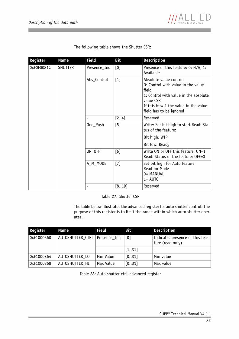
Description of the data path
GUPPY Technical Manual V4.0.1
82
The following table shows the Shutter CSR:
The table below illustrates the advanced register for auto shutter control. The purpose of this register is to limit the range within which auto shutter oper-ates.
Register Name Field Bit Description
0xF0F0081C SHUTTER Presence_Inq [0] Presence of this feature: 0: N/A; 1: Available
Abs_Control [1] Absolute value controlO: Control with value in the value field1: Control with value in the absolute value CSRIf this bit= 1 the value in the value field has to be ignored
- [2..4] Reserved
One_Push [5] Write: Set bit high to start Read: Sta-tus of the feature:
Bit high: WIP
Bit low: Ready
ON_OFF [6] Write ON or OFF this feature, ON=1 Read: Status of the feature; OFF=0
A_M_MODE [7] Set bit high for Auto featureRead for Mode0= MANUAL1= AUTO
- [8..19] Reserved
Table 27: Shutter CSR
Register Name Field Bit Description
0xF1000360 AUTOSHUTTER_CTRL Presence_Inq [0] Indicates presence of this fea-ture (read only)
[1..31] -
0xF1000364 AUTOSHUTTER_LO Min Value [0..31] Min value
0xF1000368 AUTOSHUTTER_HI Max Value [0..31] Max value
Table 28: Auto shutter ctrl. advanced register
Description of the data path
GUPPY Technical Manual V4.0.1
83
When both auto shutter and auto gain are enabled, priority is given to increasing shutter when brightness decreases. This is done to achieve the best image quality with lowest noise.
For increasing brightness, priority is given to lowering gain first for the same purpose.
Note • Values can only be changed within the limits of shutter CSR.
• Changes in auto exposure register only have an effect when auto shutter is enabled.
• Auto exposure limits are: 50..205
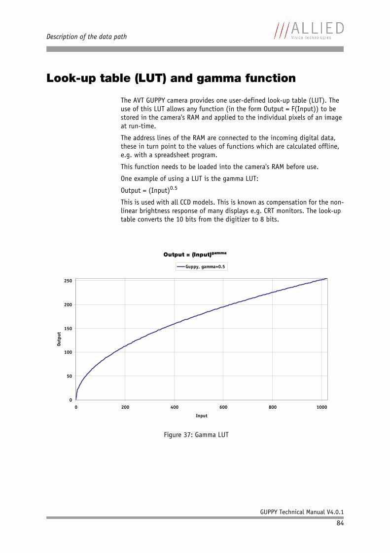
Description of the data path
GUPPY Technical Manual V4.0.1
84
Look-up table (LUT) and gamma function
The AVT GUPPY camera provides one user-defined look-up table (LUT). The use of this LUT allows any function (in the form Output = F(Input)) to be stored in the camera's RAM and applied to the individual pixels of an image at run-time.
The address lines of the RAM are connected to the incoming digital data, these in turn point to the values of functions which are calculated offline, e.g. with a spreadsheet program.
This function needs to be loaded into the camera's RAM before use.
One example of using a LUT is the gamma LUT:
Output = (Input)0.5
This is used with all CCD models. This is known as compensation for the non-linear brightness response of many displays e.g. CRT monitors. The look-up table converts the 10 bits from the digitizer to 8 bits.
Figure 37: Gamma LUT
Output = (Input)gamma
0
50
100
150
200
250
0 200 400 600 800 1000
Input
Outp
ut
Guppy, gamma=0.5
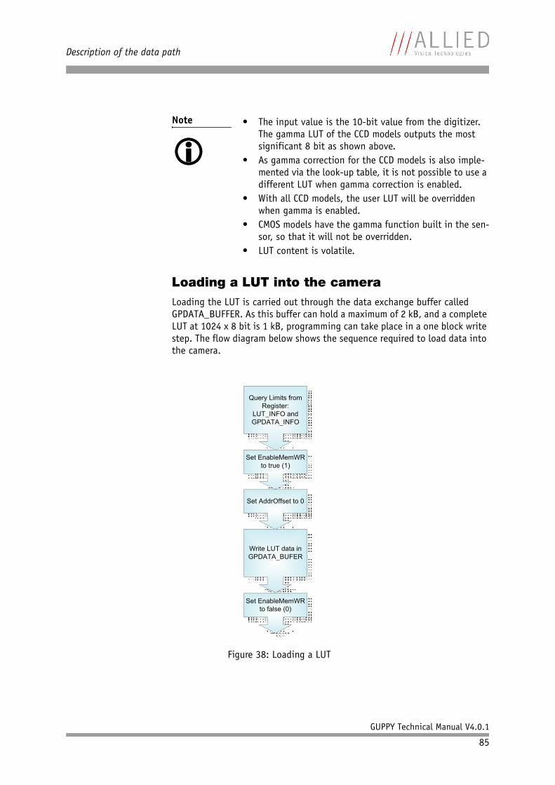
Description of the data path
GUPPY Technical Manual V4.0.1
85
Loading a LUT into the cameraLoading the LUT is carried out through the data exchange buffer called GPDATA_BUFFER. As this buffer can hold a maximum of 2 kB, and a complete LUT at 1024 x 8 bit is 1 kB, programming can take place in a one block write step. The flow diagram below shows the sequence required to load data into the camera.
Note • The input value is the 10-bit value from the digitizer. The gamma LUT of the CCD models outputs the most significant 8 bit as shown above.
• As gamma correction for the CCD models is also imple-mented via the look-up table, it is not possible to use a different LUT when gamma correction is enabled.
• With all CCD models, the user LUT will be overridden when gamma is enabled.
• CMOS models have the gamma function built in the sen-sor, so that it will not be overridden.
• LUT content is volatile.
Figure 38: Loading a LUT
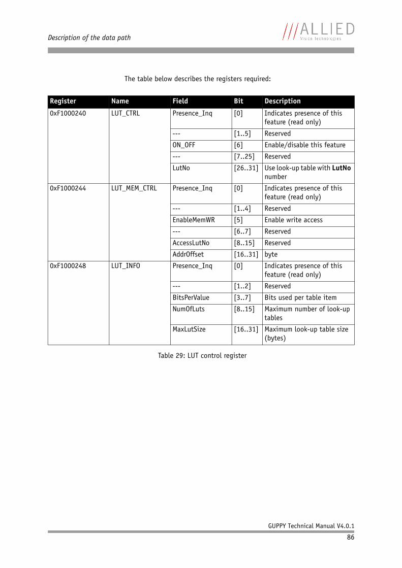
Description of the data path
GUPPY Technical Manual V4.0.1
86
The table below describes the registers required:
Register Name Field Bit Description
0xF1000240 LUT_CTRL Presence_Inq [0] Indicates presence of this feature (read only)
--- [1..5] Reserved
ON_OFF [6] Enable/disable this feature
--- [7..25] Reserved
LutNo [26..31] Use look-up table with LutNo number
0xF1000244 LUT_MEM_CTRL Presence_Inq [0] Indicates presence of this feature (read only)
--- [1..4] Reserved
EnableMemWR [5] Enable write access
--- [6..7] Reserved
AccessLutNo [8..15] Reserved
AddrOffset [16..31] byte
0xF1000248 LUT_INFO Presence_Inq [0] Indicates presence of this feature (read only)
--- [1..2] Reserved
BitsPerValue [3..7] Bits used per table item
NumOfLuts [8..15] Maximum number of look-up tables
MaxLutSize [16..31] Maximum look-up table size (bytes)
Table 29: LUT control register
Description of the data path
GUPPY Technical Manual V4.0.1
87
Binning (b/w models)
2 x and 4 x binningBinning is the process of combining neighboring pixels while being read out from the CCD chip.
GUPPY F-036 b/w cameras have this feature.
Binning is used primarily for 3 reasons:• a reduction in the number of pixels and thus the amount of data while
retaining the original image area angle• an increase in the frame rate (vertical binning only)• an improvement in the signal-to-noise ratio of the image
Signal-to-noise ratio (SNR) and signal-to-noise separation specify the quality of a signal with regard to its reproduction of intensities. The value signifies how high the ratio of noise is in regard to the maximum achievable signal intensity.
The higher this value, the better the signal quality. The unit of measurement used is generally known as the decibel (dB), a logarithmic power level. 6 dB is the signal level gain when binning two pixels, giving a theoretical SNR improvement of about 3 dB.
However, the advantages of increasing signal quality are accompanied by a reduction in resolution.
Binning is possible only in video Format_7. The type of binning used depends on the video mode.
In general, we distinguish between four types of binning:• 2 x H-binning• 2 x V-binning• 4 x H-binning• 4 x V-binning
and the full binning modes:• 2 x full binning (a combination of 2 x H-binning and 2 x V-binning)• 4 x full binning (a combination of 4 x H-binning and 4 x V-binning)
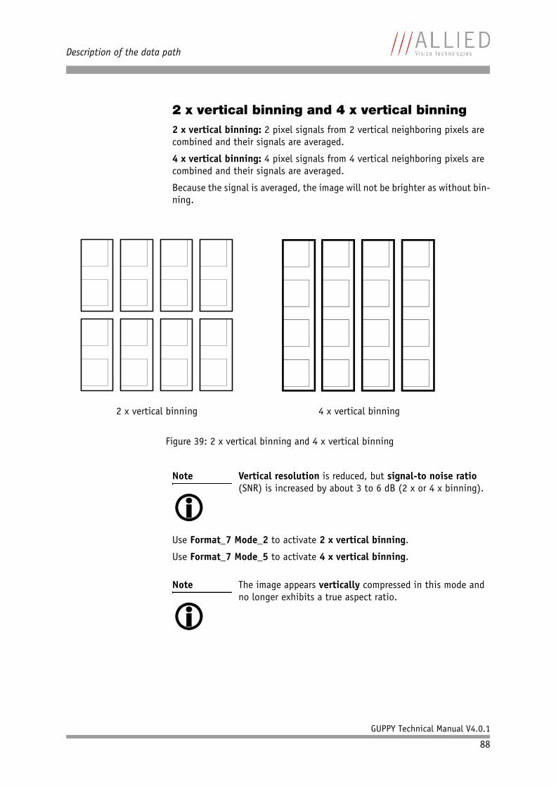
Description of the data path
GUPPY Technical Manual V4.0.1
88
2 x vertical binning and 4 x vertical binning2 x vertical binning: 2 pixel signals from 2 vertical neighboring pixels are combined and their signals are averaged.
4 x vertical binning: 4 pixel signals from 4 vertical neighboring pixels are combined and their signals are averaged.
Because the signal is averaged, the image will not be brighter as without bin-ning.
Use Format_7 Mode_2 to activate 2 x vertical binning.
Use Format_7 Mode_5 to activate 4 x vertical binning.
Figure 39: 2 x vertical binning and 4 x vertical binning
Note Vertical resolution is reduced, but signal-to noise ratio (SNR) is increased by about 3 to 6 dB (2 x or 4 x binning).
Note The image appears vertically compressed in this mode and no longer exhibits a true aspect ratio.
2 x vertical binning 4 x vertical binning
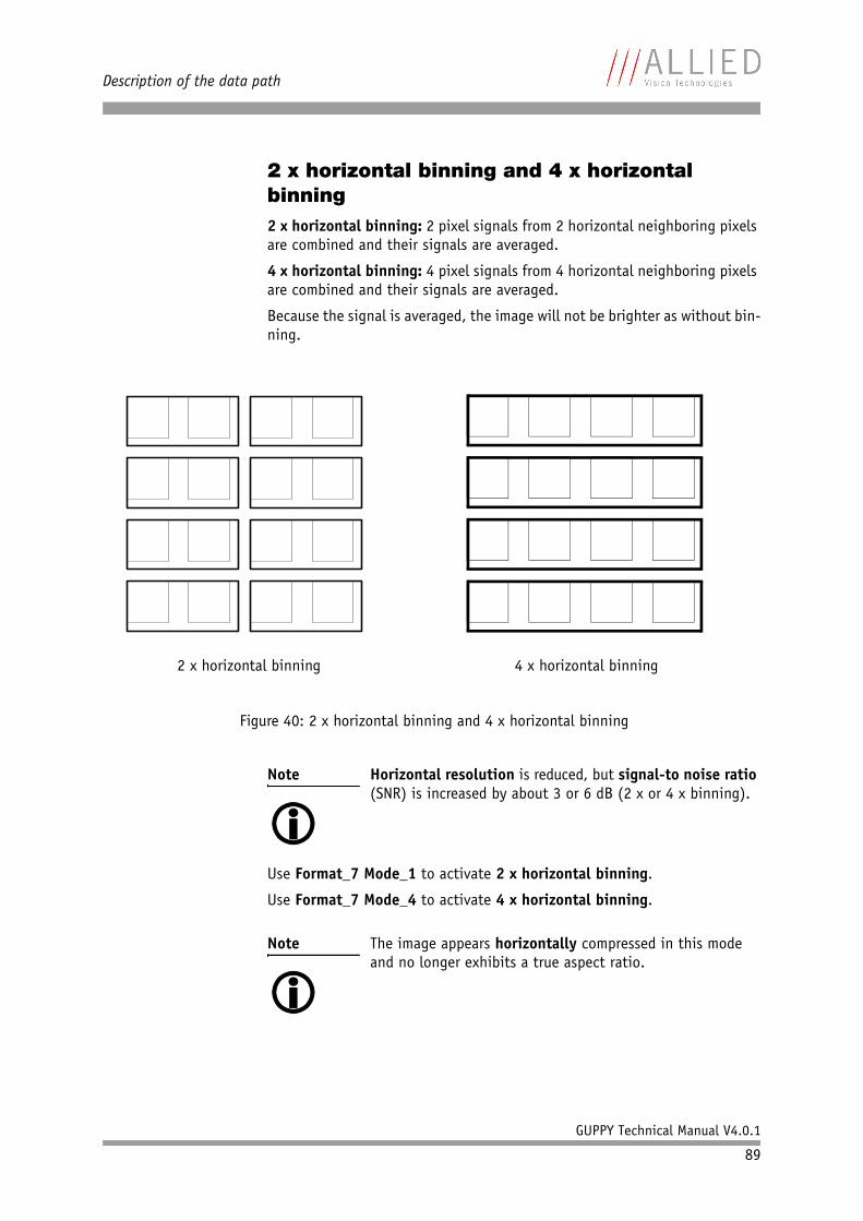
Description of the data path
GUPPY Technical Manual V4.0.1
89
2 x horizontal binning and 4 x horizontal binning2 x horizontal binning: 2 pixel signals from 2 horizontal neighboring pixels are combined and their signals are averaged.
4 x horizontal binning: 4 pixel signals from 4 horizontal neighboring pixels are combined and their signals are averaged.
Because the signal is averaged, the image will not be brighter as without bin-ning.
Use Format_7 Mode_1 to activate 2 x horizontal binning.
Use Format_7 Mode_4 to activate 4 x horizontal binning.
Figure 40: 2 x horizontal binning and 4 x horizontal binning
Note Horizontal resolution is reduced, but signal-to noise ratio (SNR) is increased by about 3 or 6 dB (2 x or 4 x binning).
Note The image appears horizontally compressed in this mode and no longer exhibits a true aspect ratio.
2 x horizontal binning 4 x horizontal binning
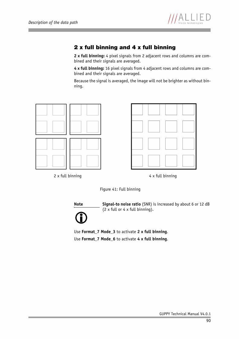
Description of the data path
GUPPY Technical Manual V4.0.1
90
2 x full binning and 4 x full binning2 x full binning: 4 pixel signals from 2 adjacent rows and columns are com-bined and their signals are averaged.
4 x full binning: 16 pixel signals from 4 adjacent rows and columns are com-bined and their signals are averaged.
Because the signal is averaged, the image will not be brighter as without bin-ning.
Use Format_7 Mode_3 to activate 2 x full binning.
Use Format_7 Mode_6 to activate 4 x full binning.
Figure 41: Full binning
Note Signal-to noise ratio (SNR) is increased by about 6 or 12 dB (2 x full or 4 x full binning).
2 x full binning 4 x full binning
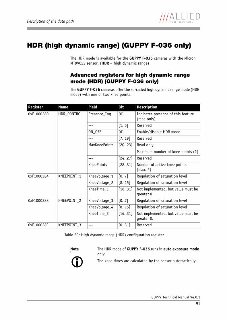
Description of the data path
GUPPY Technical Manual V4.0.1
91
HDR (high dynamic range) (GUPPY F-036 only)
The HDR mode is available for the GUPPY F-036 cameras with the Micron MT9V022 sensor. (HDR = high dynamic range)
Advanced registers for high dynamic range mode (HDR) (GUPPY F-036 only)The GUPPY F-036 cameras offer the so-called high dynamic range mode (HDR mode) with one or two knee points.
Register Name Field Bit Description
0xF1000280 HDR_CONTROL Presence_Inq [0] Indicates presence of this feature (read only)
--- [1..5] Reserved
ON_OFF [6] Enable/disable HDR mode
--- [7..19] Reserved
MaxKneePoints [20..23] Read only
Maximum number of knee points (2)
--- [24..27] Reserved
KneePoints [28..31] Number of active knee points(max. 2)
0xF1000284 KNEEPOINT_1 KneeVoltage_1 [0..7] Regulation of saturation level
KneeVoltage_2 [8..15] Regulation of saturation level
KneeTime_1 [16..31] Not implemented, but value must be greater 0
0xF1000288 KNEEPOINT_2 KneeVoltage_3 [0..7] Regulation of saturation level
KneeVoltage_4 [8..15] Regulation of saturation level
KneeTime_2 [16..31] Not implemented, but value must be greater 0.
0xF100028C KNEEPOINT_3 --- [0..31] Reserved
Table 30: High dynamic range (HDR) configuration register
Note The HDR mode of GUPPY F-036 runs in auto exposure mode only.
The knee times are calculated by the sensor automatically.
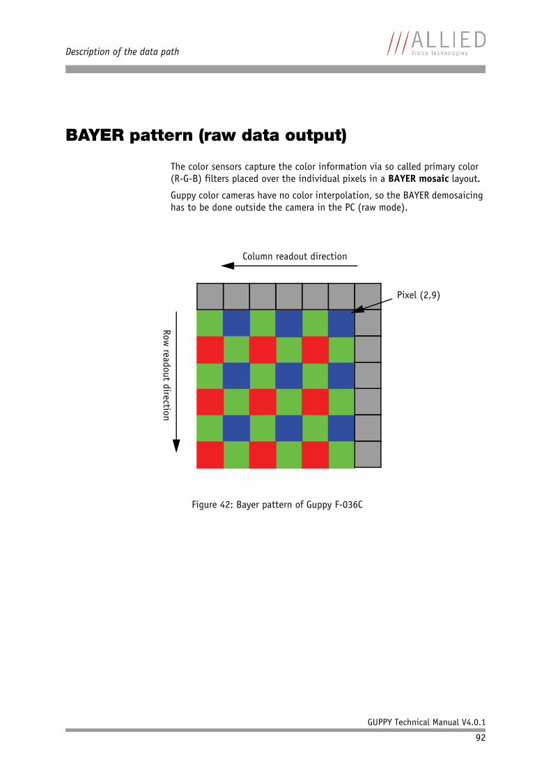
Description of the data path
GUPPY Technical Manual V4.0.1
92
BAYER pattern (raw data output)
The color sensors capture the color information via so called primary color (R-G-B) filters placed over the individual pixels in a BAYER mosaic layout.
Guppy color cameras have no color interpolation, so the BAYER demosaicing has to be done outside the camera in the PC (raw mode).
Figure 42: Bayer pattern of Guppy F-036C
Pixel (2,9)
Column readout direction
Row readout direction
Description of the data path
GUPPY Technical Manual V4.0.1
93
Serial interface
All GUPPY cameras are equipped with the SIO (serial input/output) feature as described in IIDC V1.31. This means that the GUPPYs serial interface which is used for firmware upgrades can also be used as a general RS232 interface.
Data written to a specific address in the IEEE 1394 address range will be sent through the serial interface. Incoming serial interface data is put in the cam-era buffer and can be polled from here via simple read commands . Control-ling registers enable the settings of baud rates and the check of buffer sizes and serial interface errors.
Base address for the function is: F0F02100h.
Note • Hardware handshaking is not supported.• Typical PC hardware does not support 230400 bps.
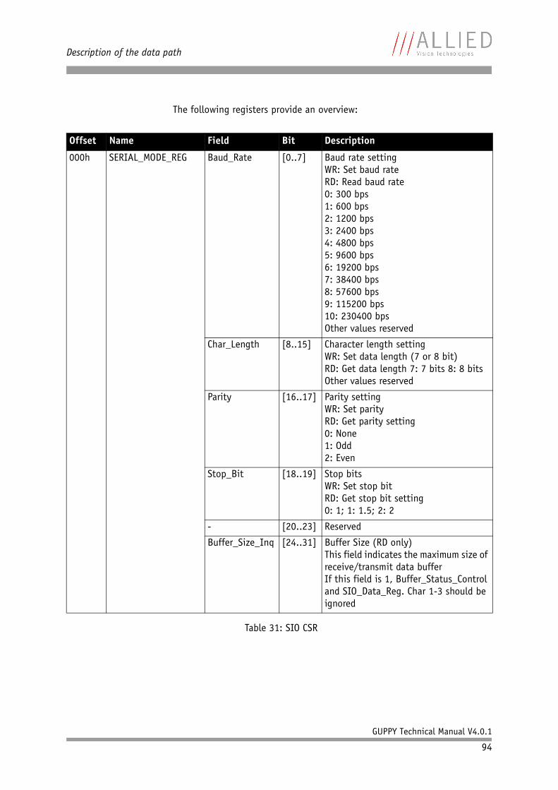
Description of the data path
GUPPY Technical Manual V4.0.1
94
The following registers provide an overview:
Offset Name Field Bit Description
000h SERIAL_MODE_REG Baud_Rate [0..7] Baud rate settingWR: Set baud rateRD: Read baud rate0: 300 bps1: 600 bps2: 1200 bps 3: 2400 bps 4: 4800 bps 5: 9600 bps 6: 19200 bps7: 38400 bps8: 57600 bps9: 115200 bps10: 230400 bpsOther values reserved
Char_Length [8..15] Character length settingWR: Set data length (7 or 8 bit)RD: Get data length 7: 7 bits 8: 8 bitsOther values reserved
Parity [16..17] Parity settingWR: Set parityRD: Get parity setting0: None1: Odd2: Even
Stop_Bit [18..19] Stop bitsWR: Set stop bitRD: Get stop bit setting0: 1; 1: 1.5; 2: 2
- [20..23] Reserved
Buffer_Size_Inq [24..31] Buffer Size (RD only)This field indicates the maximum size of receive/transmit data bufferIf this field is 1, Buffer_Status_Control and SIO_Data_Reg. Char 1-3 should be ignored
Table 31: SIO CSR
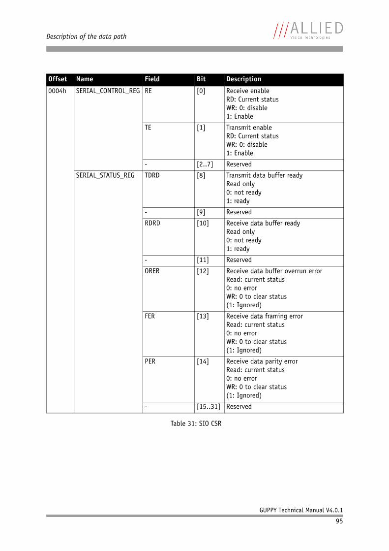
Description of the data path
GUPPY Technical Manual V4.0.1
95
0004h SERIAL_CONTROL_REG RE [0] Receive enableRD: Current statusWR: 0: disable1: Enable
TE [1] Transmit enableRD: Current statusWR: 0: disable1: Enable
- [2..7] Reserved
SERIAL_STATUS_REG TDRD [8] Transmit data buffer readyRead only0: not ready1: ready
- [9] Reserved
RDRD [10] Receive data buffer readyRead only0: not ready1: ready
- [11] Reserved
ORER [12] Receive data buffer overrun errorRead: current status0: no errorWR: 0 to clear status(1: Ignored)
FER [13] Receive data framing errorRead: current status0: no errorWR: 0 to clear status(1: Ignored)
PER [14] Receive data parity errorRead: current status0: no errorWR: 0 to clear status(1: Ignored)
- [15..31] Reserved
Offset Name Field Bit Description
Table 31: SIO CSR
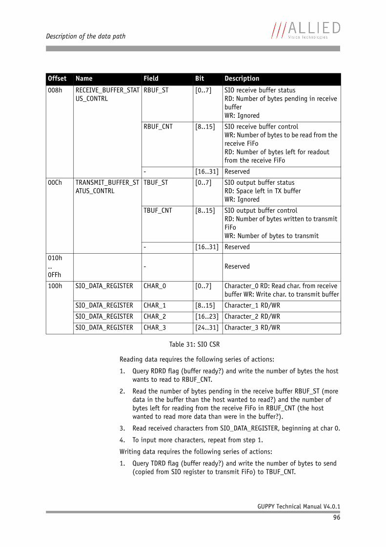
Description of the data path
GUPPY Technical Manual V4.0.1
96
Reading data requires the following series of actions:
1. Query RDRD flag (buffer ready?) and write the number of bytes the host wants to read to RBUF_CNT.
2. Read the number of bytes pending in the receive buffer RBUF_ST (more data in the buffer than the host wanted to read?) and the number of bytes left for reading from the receive FiFo in RBUF_CNT (the host wanted to read more data than were in the buffer?).
3. Read received characters from SIO_DATA_REGISTER, beginning at char 0.
4. To input more characters, repeat from step 1.
Writing data requires the following series of actions:
1. Query TDRD flag (buffer ready?) and write the number of bytes to send (copied from SIO register to transmit FiFo) to TBUF_CNT.
008h RECEIVE_BUFFER_STATUS_CONTRL
RBUF_ST [0..7] SIO receive buffer statusRD: Number of bytes pending in receive bufferWR: Ignored
RBUF_CNT [8..15] SIO receive buffer controlWR: Number of bytes to be read from the receive FiFoRD: Number of bytes left for readout from the receive FiFo
- [16..31] Reserved
00Ch TRANSMIT_BUFFER_STATUS_CONTRL
TBUF_ST [0..7] SIO output buffer statusRD: Space left in TX bufferWR: Ignored
TBUF_CNT [8..15] SIO output buffer controlRD: Number of bytes written to transmit FiFoWR: Number of bytes to transmit
- [16..31] Reserved
010h..0FFh
- Reserved
100h SIO_DATA_REGISTER CHAR_0 [0..7] Character_0 RD: Read char. from receive buffer WR: Write char. to transmit buffer
SIO_DATA_REGISTER CHAR_1 [8..15] Character_1 RD/WR
SIO_DATA_REGISTER CHAR_2 [16..23] Character_2 RD/WR
SIO_DATA_REGISTER CHAR_3 [24..31] Character_3 RD/WR
Offset Name Field Bit Description
Table 31: SIO CSR
Description of the data path
GUPPY Technical Manual V4.0.1
97
2. Read the available data space left in TBUF_ST (if the buffer can hold more bytes than are to be transmitted) and number of bytes written to transmit buffer in TBUF_CNT (if more data are to be transmitted than fit in the buffer).
3. Write character to SIO_DATA_REGISTER, beginning at char 0.
4. To output more characters, repeat from step 1.
Note • Contact your local dealer if you require further informa-tion or additional test programs or software.
• AVT recommends the use of Hyperterminal™ or other communication programs to test the functionality of this feature.
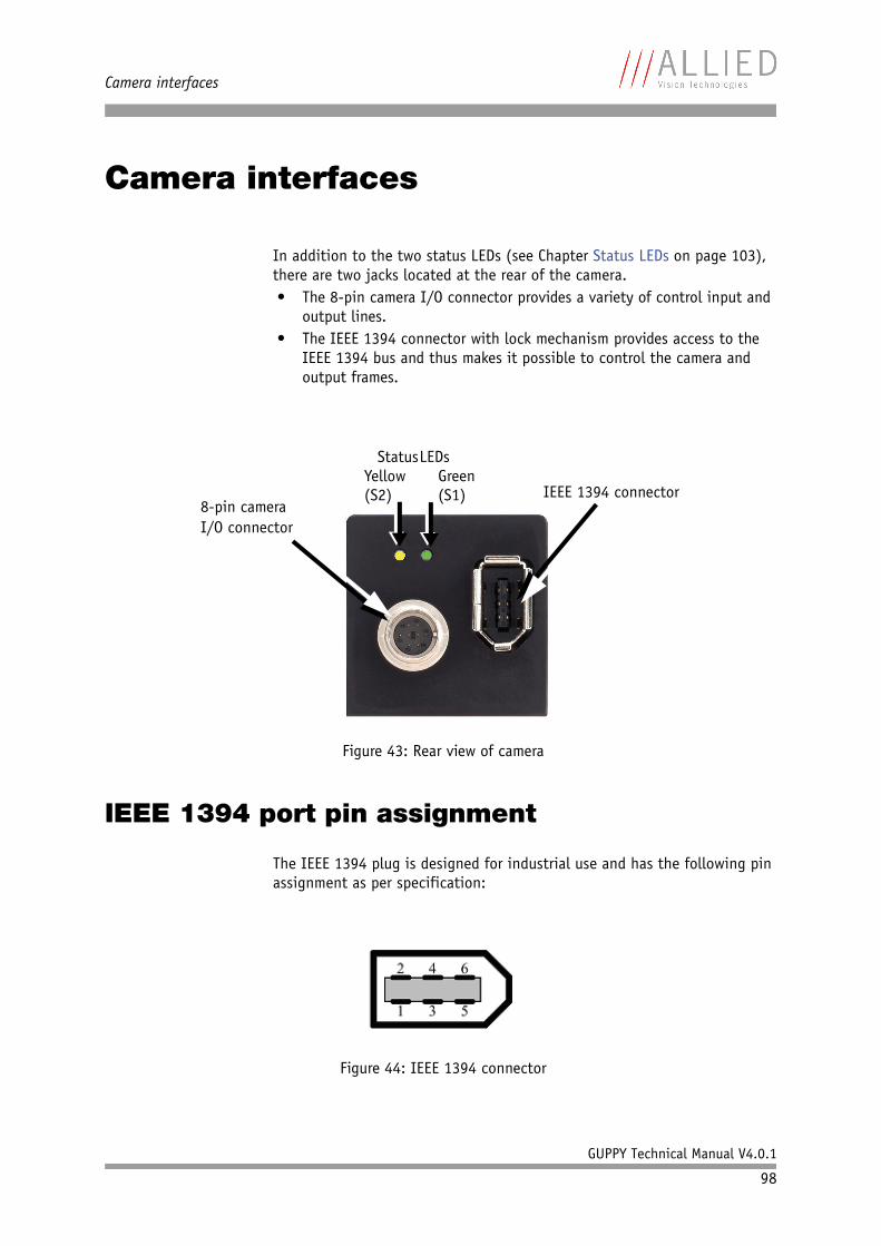
Camera interfaces
GUPPY Technical Manual V4.0.1
98
Camera interfaces
In addition to the two status LEDs (see Chapter Status LEDs on page 103), there are two jacks located at the rear of the camera.• The 8-pin camera I/O connector provides a variety of control input and
output lines.• The IEEE 1394 connector with lock mechanism provides access to the
IEEE 1394 bus and thus makes it possible to control the camera and output frames.
IEEE 1394 port pin assignment
The IEEE 1394 plug is designed for industrial use and has the following pin assignment as per specification:
Figure 43: Rear view of camera
Figure 44: IEEE 1394 connector
Status LEDs
8-pin cameraIEEE 1394 connector
I/O connector
Yellow(S2)
Green(S1)
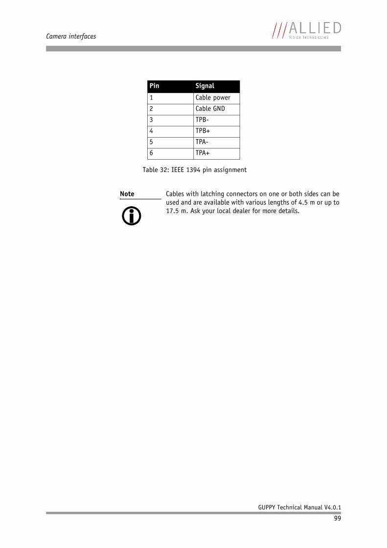
Camera interfaces
GUPPY Technical Manual V4.0.1
99
Pin Signal
1 Cable power
2 Cable GND
3 TPB-
4 TPB+
5 TPA-
6 TPA+
Table 32: IEEE 1394 pin assignment
Note Cables with latching connectors on one or both sides can be used and are available with various lengths of 4.5 m or up to 17.5 m. Ask your local dealer for more details.
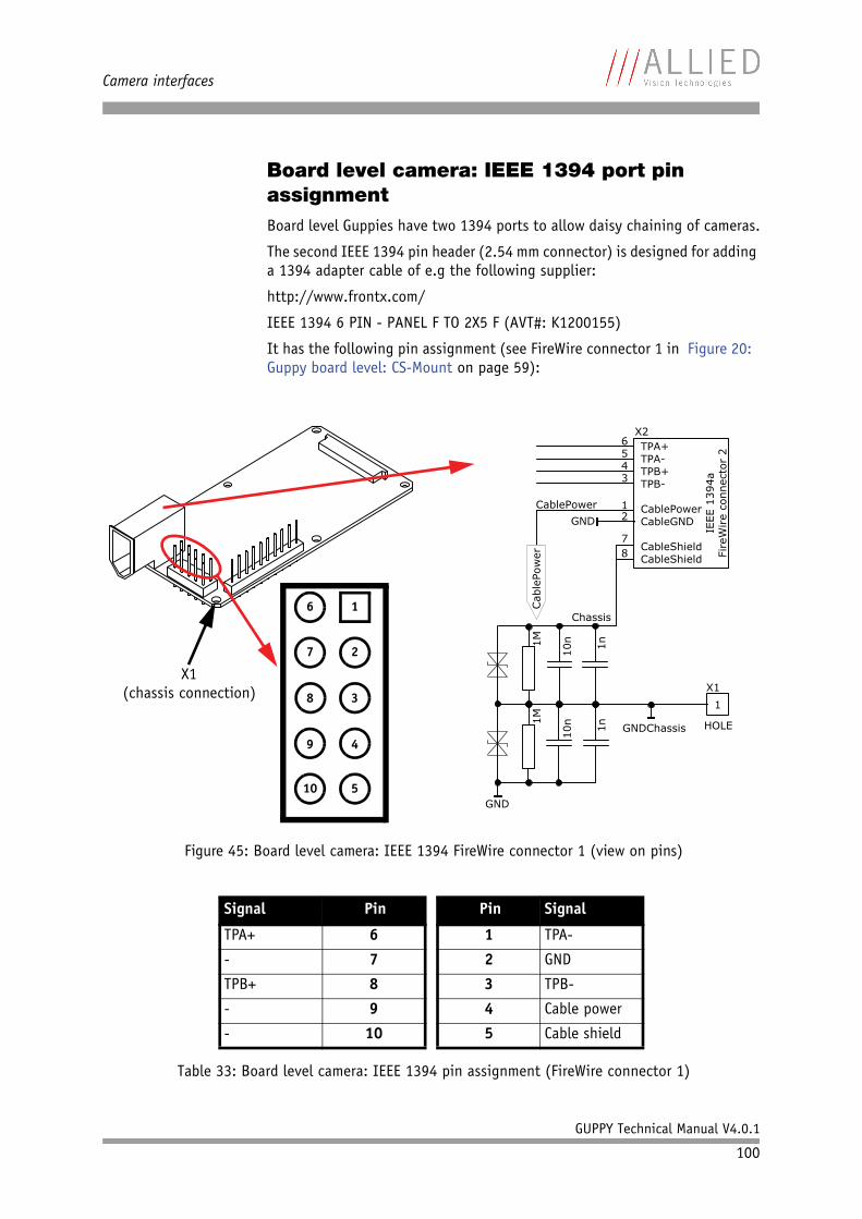
Camera interfaces
GUPPY Technical Manual V4.0.1
100
Board level camera: IEEE 1394 port pin assignmentBoard level Guppies have two 1394 ports to allow daisy chaining of cameras.
The second IEEE 1394 pin header (2.54 mm connector) is designed for adding a 1394 adapter cable of e.g the following supplier:
http://www.frontx.com/
IEEE 1394 6 PIN - PANEL F TO 2X5 F (AVT#: K1200155)
It has the following pin assignment (see FireWire connector 1 in Figure 20: Guppy board level: CS-Mount on page 59):
Figure 45: Board level camera: IEEE 1394 FireWire connector 1 (view on pins)
Signal Pin Pin Signal
TPA+ 6 1 TPA-
- 7 2 GND
TPB+ 8 3 TPB-
- 9 4 Cable power
- 10 5 Cable shield
Table 33: Board level camera: IEEE 1394 pin assignment (FireWire connector 1)
1
2
3
4
5
6
7
8
9
10
X1(chassis connection)
TPA+TPA-TPB+TPB-
CablePowerCableGND
CableShieldCableShield
GNDChassis
IEEE 1
394a
FireW
ire c
onnecto
r 2
Cable
Pow
er
CablePower
GND
HOLE
X1
6543
12
7
8
1
1M
1M
10n
1n
10n
1n
X2
GND
Chassis
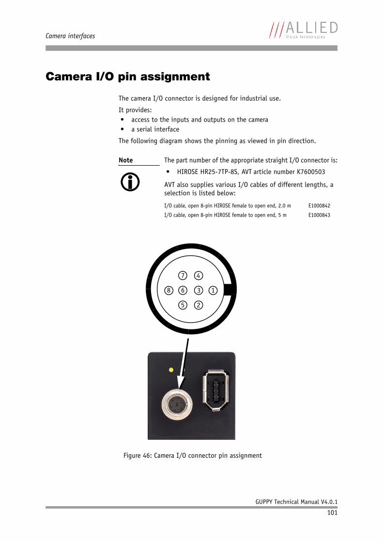
Camera interfaces
GUPPY Technical Manual V4.0.1
101
Camera I/O pin assignment
The camera I/O connector is designed for industrial use.
It provides:• access to the inputs and outputs on the camera• a serial interface
The following diagram shows the pinning as viewed in pin direction.
Note The part number of the appropriate straight I/O connector is:
• HIROSE HR25-7TP-8S, AVT article number K7600503
AVT also supplies various I/O cables of different lengths, a selection is listed below:
I/O cable, open 8-pin HIROSE female to open end, 2.0 m E1000842
I/O cable, open 8-pin HIROSE female to open end, 5 m E1000843
Figure 46: Camera I/O connector pin assignment
13
4
6
7
8
5 2
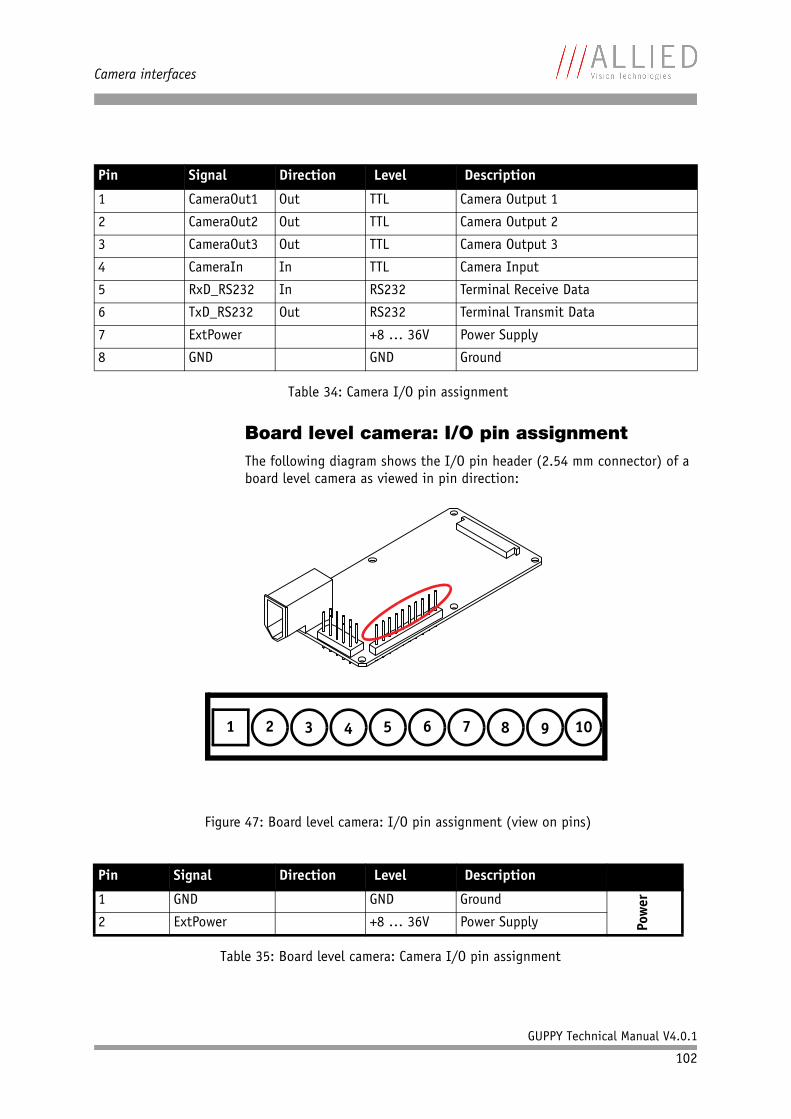
Camera interfaces
GUPPY Technical Manual V4.0.1
102
Board level camera: I/O pin assignmentThe following diagram shows the I/O pin header (2.54 mm connector) of a board level camera as viewed in pin direction:
Pin Signal Direction Level Description
1 CameraOut1 Out TTL Camera Output 1
2 CameraOut2 Out TTL Camera Output 2
3 CameraOut3 Out TTL Camera Output 3
4 CameraIn In TTL Camera Input
5 RxD_RS232 In RS232 Terminal Receive Data
6 TxD_RS232 Out RS232 Terminal Transmit Data
7 ExtPower +8 … 36V Power Supply
8 GND GND Ground
Table 34: Camera I/O pin assignment
Figure 47: Board level camera: I/O pin assignment (view on pins)
Pin Signal Direction Level Description
1 GND GND Ground
Pow
er
2 ExtPower +8 … 36V Power Supply
Table 35: Board level camera: Camera I/O pin assignment
1 2 3 4 5 6 7 8 9 10
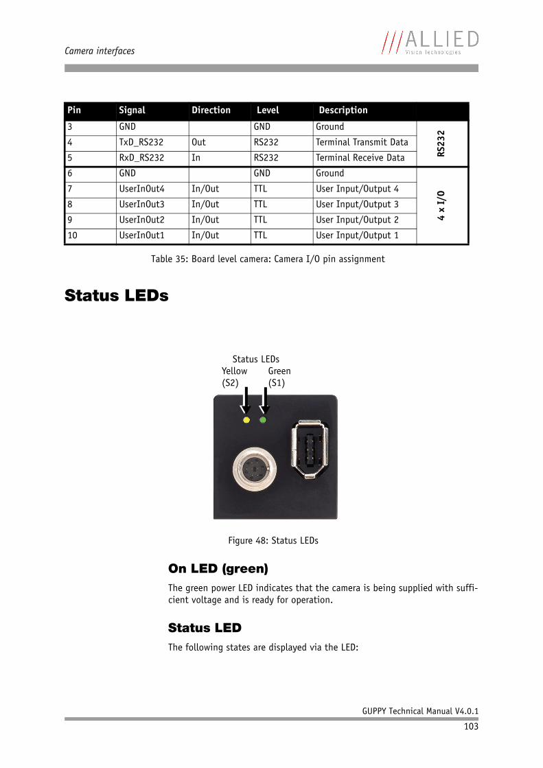
Camera interfaces
GUPPY Technical Manual V4.0.1
103
Status LEDs
On LED (green)The green power LED indicates that the camera is being supplied with suffi-cient voltage and is ready for operation.
Status LEDThe following states are displayed via the LED:
3 GND GND Ground
RS23
2
4 TxD_RS232 Out RS232 Terminal Transmit Data
5 RxD_RS232 In RS232 Terminal Receive Data
6 GND GND Ground
4 x
I/O7 UserInOut4 In/Out TTL User Input/Output 4
8 UserInOut3 In/Out TTL User Input/Output 3
9 UserInOut2 In/Out TTL User Input/Output 2
10 UserInOut1 In/Out TTL User Input/Output 1
Figure 48: Status LEDs
Pin Signal Direction Level Description
Table 35: Board level camera: Camera I/O pin assignment
Status LEDsYellow(S2)
Green(S1)
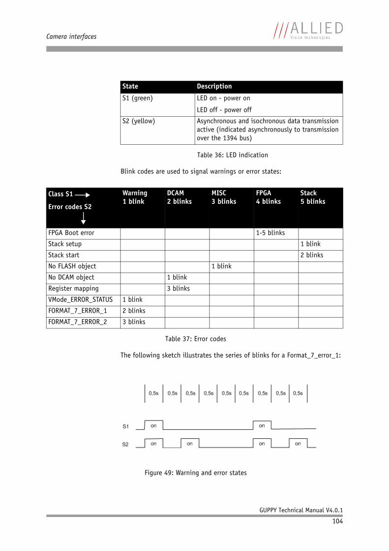
Camera interfaces
GUPPY Technical Manual V4.0.1
104
Blink codes are used to signal warnings or error states:
The following sketch illustrates the series of blinks for a Format_7_error_1:
State Description
S1 (green) LED on - power on
LED off - power off
S2 (yellow) Asynchronous and isochronous data transmission active (indicated asynchronously to transmission over the 1394 bus)
Table 36: LED indication
Class S1
Error codes S2
Warning1 blink
DCAM2 blinks
MISC 3 blinks
FPGA4 blinks
Stack5 blinks
FPGA Boot error 1-5 blinks
Stack setup 1 blink
Stack start 2 blinks
No FLASH object 1 blink
No DCAM object 1 blink
Register mapping 3 blinks
VMode_ERROR_STATUS 1 blink
FORMAT_7_ERROR_1 2 blinks
FORMAT_7_ERROR_2 3 blinks
Table 37: Error codes
Figure 49: Warning and error states
Camera interfaces
GUPPY Technical Manual V4.0.1
105
You should wait for at least 2 full cycles because the display of blinking codes starts asynchronously - e.g. on the second blink from S2.
Operating the camera
Power for the camera is supplied either via the FireWire™ bus or the camera I/O connector’s pin 7.
The input voltage must be within the following range:
Vcc min.: +8 V
Vcc max.: +36 V
Control and video data signals
Guppy cameras have 1 input and 3 outputs. These can be configured by soft-ware. The different modes are described below.
Note • An input voltage of 12 V is recommended for most effi-cient use of the camera.
• As mentioned above: The camera I/O connector sup-plies power to the camera via a diode. This means that there is no power out at pin 7 if the camera is powered via the bus. Consult the factory if you need power out-put at this pin instead of power in.
Note Guppy board level cameras have 4 bidirectional inputs/outputs: Outputs can be disabled via the Output Control Reg-ister.
For further details, read Chapter Board level cameras: inputs and outputs on page 116 and Chapter Board level cameras: pulse-width modulation on page 117.
Warning The Guppy outputs are not short-circuit-proof.
If there occurs a short-circuit at the outputs, the output driver will be damaged.
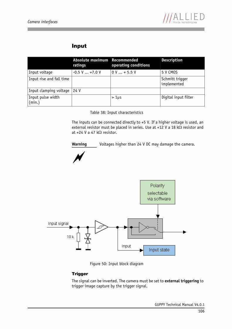
Camera interfaces
GUPPY Technical Manual V4.0.1
106
Input
The inputs can be connected directly to +5 V. If a higher voltage is used, an external resistor must be placed in series. Use at +12 V a 18 kΩ resistor and at +24 V a 47 kΩ resistor.
Trigger
The signal can be inverted. The camera must be set to external triggering to trigger image capture by the trigger signal.
Absolute maximumratings
Recommendedoperating conditions
Description
Input voltage -0.5 V ... +7.0 V 0 V ... + 5.5 V 5 V CMOS
Input rise and fall time Schmitt triggerimplemented
Input clamping voltage 24 V
Input pulse width (min.)
> 1µs Digital input filter
Table 38: Input characteristics
Warning Voltages higher than 24 V DC may damage the camera.
Figure 50: Input block diagram
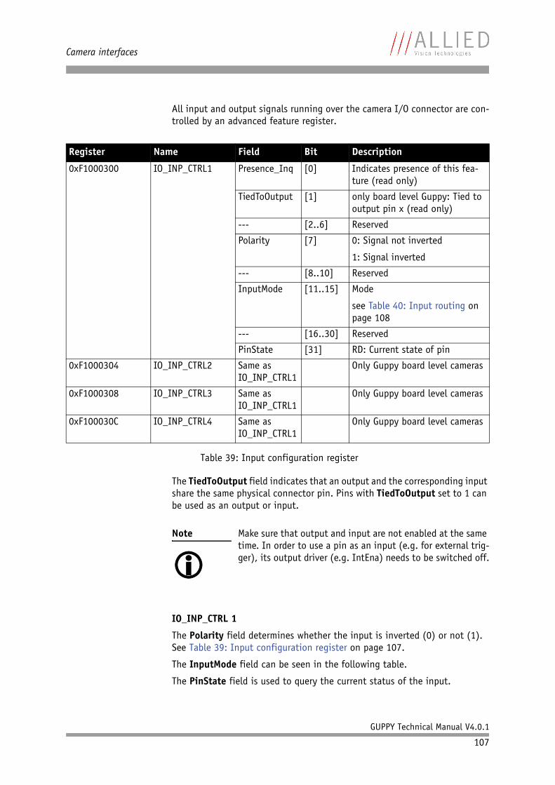
Camera interfaces
GUPPY Technical Manual V4.0.1
107
All input and output signals running over the camera I/O connector are con-trolled by an advanced feature register.
The TiedToOutput field indicates that an output and the corresponding input share the same physical connector pin. Pins with TiedToOutput set to 1 can be used as an output or input.
IO_INP_CTRL 1
The Polarity field determines whether the input is inverted (0) or not (1). See Table 39: Input configuration register on page 107.
The InputMode field can be seen in the following table.
The PinState field is used to query the current status of the input.
Register Name Field Bit Description
0xF1000300 IO_INP_CTRL1 Presence_Inq [0] Indicates presence of this fea-ture (read only)
TiedToOutput [1] only board level Guppy: Tied to output pin x (read only)
--- [2..6] Reserved
Polarity [7] 0: Signal not inverted
1: Signal inverted
--- [8..10] Reserved
InputMode [11..15] Mode
see Table 40: Input routing on page 108
--- [16..30] Reserved
PinState [31] RD: Current state of pin
0xF1000304 IO_INP_CTRL2 Same as IO_INP_CTRL1
Only Guppy board level cameras
0xF1000308 IO_INP_CTRL3 Same as IO_INP_CTRL1
Only Guppy board level cameras
0xF100030C IO_INP_CTRL4 Same as IO_INP_CTRL1
Only Guppy board level cameras
Table 39: Input configuration register
Note Make sure that output and input are not enabled at the same time. In order to use a pin as an input (e.g. for external trig-ger), its output driver (e.g. IntEna) needs to be switched off.
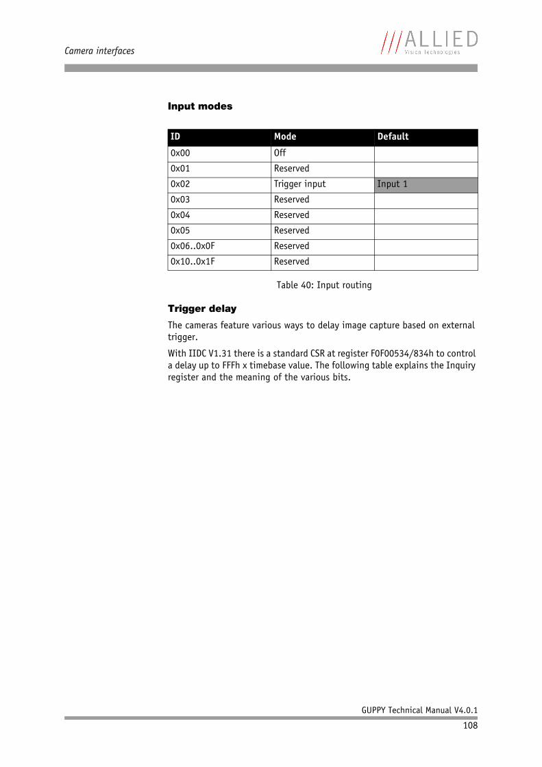
Camera interfaces
GUPPY Technical Manual V4.0.1
108
Input modes
Trigger delay
The cameras feature various ways to delay image capture based on external trigger.
With IIDC V1.31 there is a standard CSR at register F0F00534/834h to control a delay up to FFFh x timebase value. The following table explains the Inquiry register and the meaning of the various bits.
ID Mode Default
0x00 Off
0x01 Reserved
0x02 Trigger input Input 1
0x03 Reserved
0x04 Reserved
0x05 Reserved
0x06..0x0F Reserved
0x10..0x1F Reserved
Table 40: Input routing
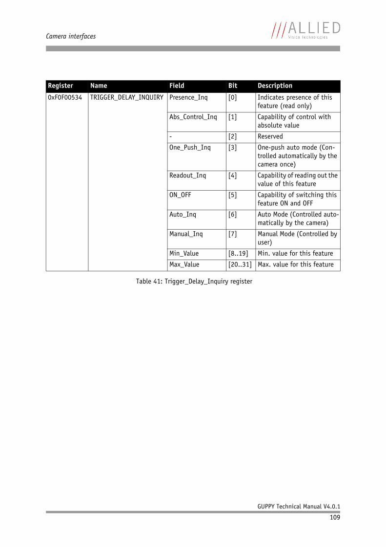
Camera interfaces
GUPPY Technical Manual V4.0.1
109
Register Name Field Bit Description
0xF0F00534 TRIGGER_DELAY_INQUIRY Presence_Inq [0] Indicates presence of this feature (read only)
Abs_Control_Inq [1] Capability of control with absolute value
- [2] Reserved
One_Push_Inq [3] One-push auto mode (Con-trolled automatically by the camera once)
Readout_Inq [4] Capability of reading out the value of this feature
ON_OFF [5] Capability of switching this feature ON and OFF
Auto_Inq [6] Auto Mode (Controlled auto-matically by the camera)
Manual_Inq [7] Manual Mode (Controlled by user)
Min_Value [8..19] Min. value for this feature
Max_Value [20..31] Max. value for this feature
Table 41: Trigger_Delay_Inquiry register
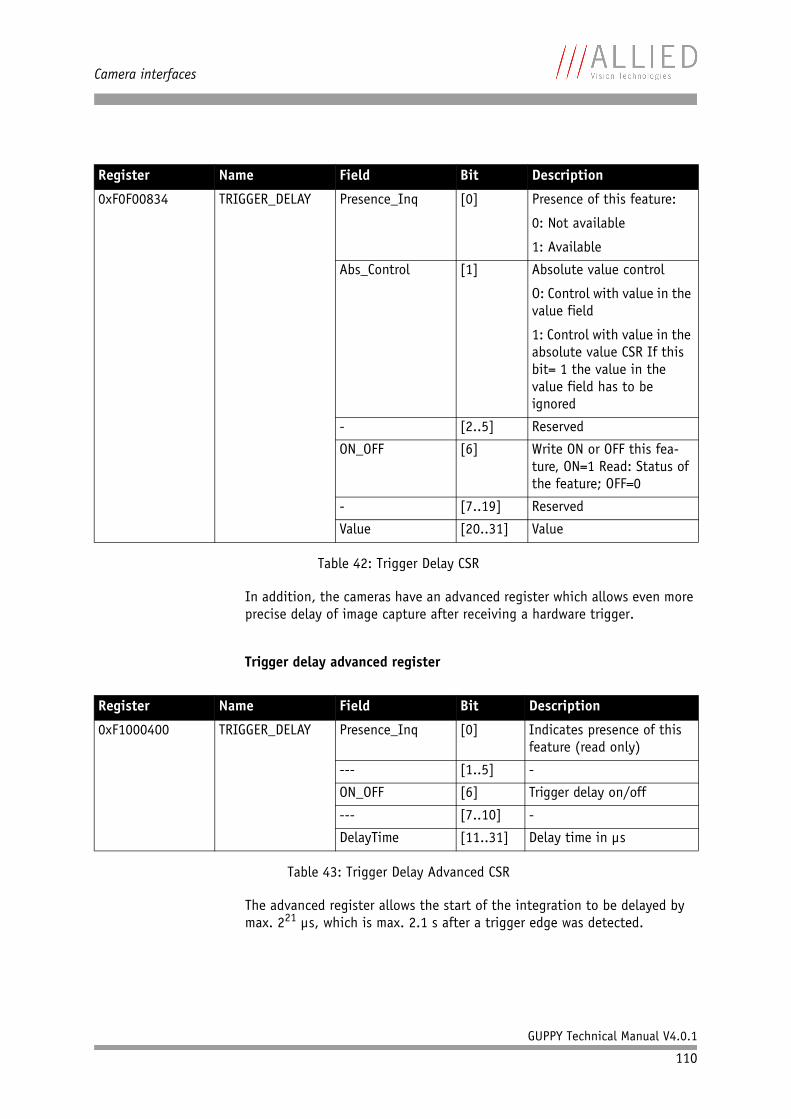
Camera interfaces
GUPPY Technical Manual V4.0.1
110
In addition, the cameras have an advanced register which allows even more precise delay of image capture after receiving a hardware trigger.
Trigger delay advanced register
The advanced register allows the start of the integration to be delayed by max. 221 µs, which is max. 2.1 s after a trigger edge was detected.
Register Name Field Bit Description
0xF0F00834 TRIGGER_DELAY Presence_Inq [0] Presence of this feature:
0: Not available
1: Available
Abs_Control [1] Absolute value control
O: Control with value in the value field
1: Control with value in the absolute value CSR If this bit= 1 the value in the value field has to be ignored
- [2..5] Reserved
ON_OFF [6] Write ON or OFF this fea-ture, ON=1 Read: Status of the feature; OFF=0
- [7..19] Reserved
Value [20..31] Value
Table 42: Trigger Delay CSR
Register Name Field Bit Description
0xF1000400 TRIGGER_DELAY Presence_Inq [0] Indicates presence of this feature (read only)
--- [1..5] -
ON_OFF [6] Trigger delay on/off
--- [7..10] -
DelayTime [11..31] Delay time in µs
Table 43: Trigger Delay Advanced CSR
Camera interfaces
GUPPY Technical Manual V4.0.1
111
OutputsThe standard Guppy camera has 3 inverting outputs.
Output features are configured by software. Any signal can be placed on any output.
The main features of output signals are described below:
Note • This feature works with external Trigger_Mode_0 only.
Outputs Operating Conditions
Output voltage 0 ... 5.5 V
Output current Max. ± 20 mA
Table 44: Output characteristics
Signal Description
IntEna (Integration Enable) signal This signal displays the time in which exposure was made. By using a register this output can be delayed up to 1.05 seconds.
Fval (Frame valid) signal This feature signals readout from the sensor. This signal Fval follows IntEna.
Busy signal This signal appears when:
• the exposure is being made or• the sensor is being read out or• data transmission is active.
Table 45: Output signals
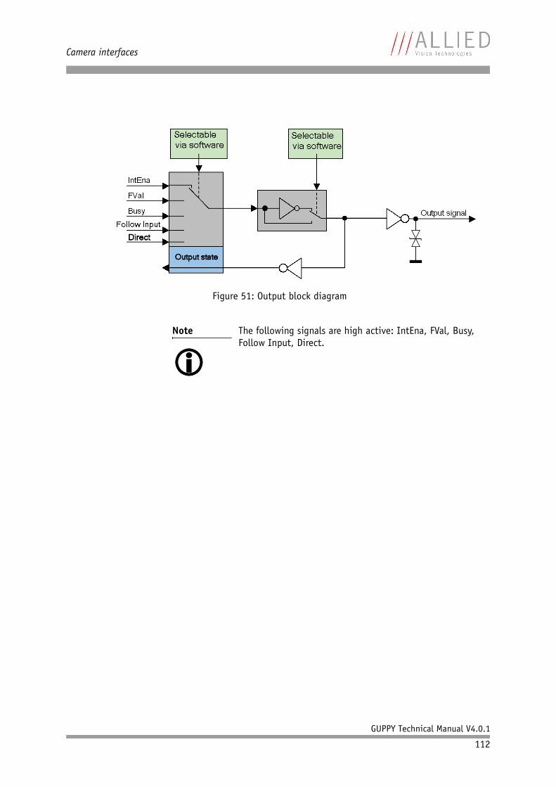
Camera interfaces
GUPPY Technical Manual V4.0.1
112
Figure 51: Output block diagram
Note The following signals are high active: IntEna, FVal, Busy,Follow Input, Direct.
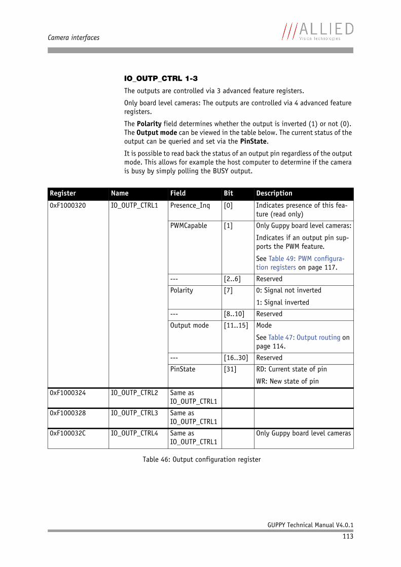
Camera interfaces
GUPPY Technical Manual V4.0.1
113
IO_OUTP_CTRL 1-3
The outputs are controlled via 3 advanced feature registers.
Only board level cameras: The outputs are controlled via 4 advanced feature registers.
The Polarity field determines whether the output is inverted (1) or not (0). The Output mode can be viewed in the table below. The current status of the output can be queried and set via the PinState.
It is possible to read back the status of an output pin regardless of the output mode. This allows for example the host computer to determine if the camera is busy by simply polling the BUSY output.
Register Name Field Bit Description
0xF1000320 IO_OUTP_CTRL1 Presence_Inq [0] Indicates presence of this fea-ture (read only)
PWMCapable [1] Only Guppy board level cameras:
Indicates if an output pin sup-ports the PWM feature.
See Table 49: PWM configura-tion registers on page 117.
--- [2..6] Reserved
Polarity [7] 0: Signal not inverted
1: Signal inverted
--- [8..10] Reserved
Output mode [11..15] Mode
See Table 47: Output routing on page 114.
--- [16..30] Reserved
PinState [31] RD: Current state of pin
WR: New state of pin
0xF1000324 IO_OUTP_CTRL2 Same as IO_OUTP_CTRL1
0xF1000328 IO_OUTP_CTRL3 Same as IO_OUTP_CTRL1
0xF100032C IO_OUTP_CTRL4 Same as IO_OUTP_CTRL1
Only Guppy board level cameras
Table 46: Output configuration register
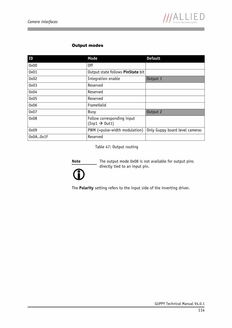
Camera interfaces
GUPPY Technical Manual V4.0.1
114
Output modes
The Polarity setting refers to the input side of the inverting driver.
ID Mode Default
0x00 Off
0x01 Output state follows PinState bit
0x02 Integration enable Output 1
0x03 Reserved
0x04 Reserved
0x05 Reserved
0x06 FrameValid
0x07 Busy Output 2
0x08 Follow corresponding input(Inp1 Out1)
0x09 PWM (=pulse-width modulation) Only Guppy board level cameras
0x0A..0x1F Reserved
Table 47: Output routing
Note The output mode 0x08 is not available for output pins directly tied to an input pin.
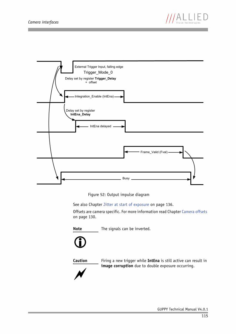
Camera interfaces
GUPPY Technical Manual V4.0.1
115
See also Chapter Jitter at start of exposure on page 136.
Offsets are camera specific. For more information read Chapter Camera offsets on page 130.
Figure 52: Output impulse diagram
Note The signals can be inverted.
Caution Firing a new trigger while IntEna is still active can result in image corruption due to double exposure occurring.
External Trigger Input, falling edge
Integration_Enable (IntEna)
IntEna delayed
Frame_Valid (Fval)
Busy
Delay set by register Trigger_Delay
+ offset
Delay set by register
IntEna_Delay
Trigger_Mode_0
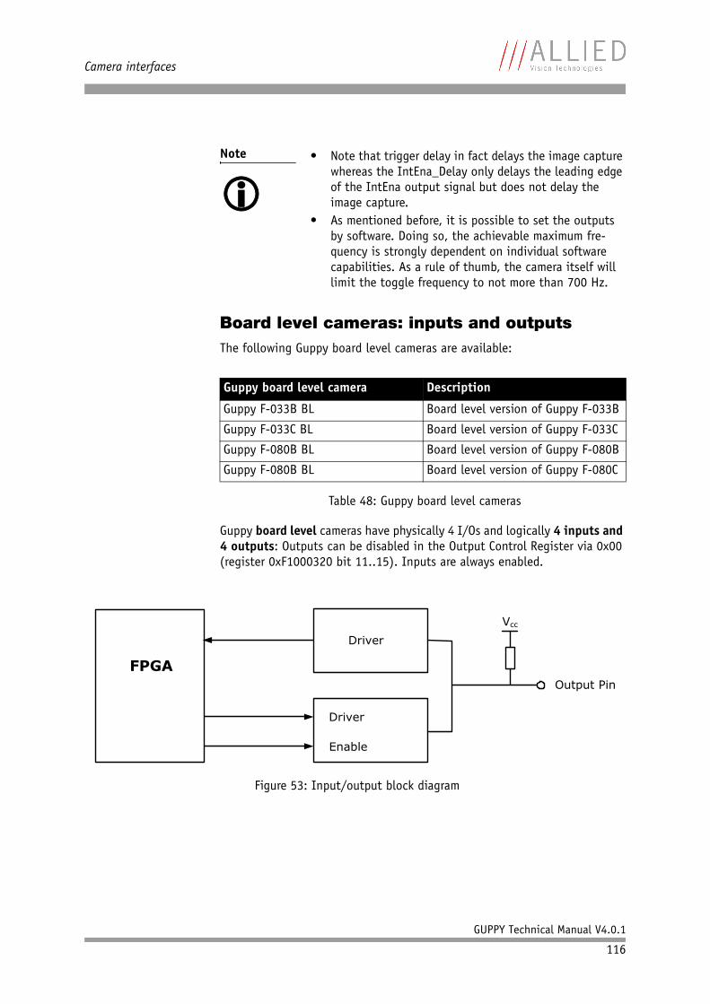
Camera interfaces
GUPPY Technical Manual V4.0.1
116
Board level cameras: inputs and outputsThe following Guppy board level cameras are available:
Guppy board level cameras have physically 4 I/Os and logically 4 inputs and 4 outputs: Outputs can be disabled in the Output Control Register via 0x00 (register 0xF1000320 bit 11..15). Inputs are always enabled.
Note • Note that trigger delay in fact delays the image capture whereas the IntEna_Delay only delays the leading edge of the IntEna output signal but does not delay the image capture.
• As mentioned before, it is possible to set the outputs by software. Doing so, the achievable maximum fre-quency is strongly dependent on individual software capabilities. As a rule of thumb, the camera itself will limit the toggle frequency to not more than 700 Hz.
Guppy board level camera Description
Guppy F-033B BL Board level version of Guppy F-033B
Guppy F-033C BL Board level version of Guppy F-033C
Guppy F-080B BL Board level version of Guppy F-080B
Guppy F-080B BL Board level version of Guppy F-080C
Table 48: Guppy board level cameras
Figure 53: Input/output block diagram
FPGA
Driver
Driver
Enable
Vcc
Output Pin
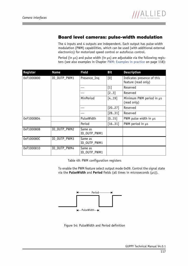
Camera interfaces
GUPPY Technical Manual V4.0.1
117
Board level cameras: pulse-width modulationThe 4 inputs and 4 outputs are independent. Each output has pulse-width modulation (PWM) capabilities, which can be used (with additional external electronics) for motorized speed control or autofocus control.
Period (in µs) and pulse width (in µs) are adjustable via the following regis-ters (see also examples in Chapter PWM: Examples in practice on page 118):
To enable the PWM feature select output mode 0x09. Control the signal state via the PulseWidth and Period fields (all times in microseconds (µs)).
Register Name Field Bit Description
0xF1000800 IO_OUTP_PWM1 Presence_Inq [0] Indicates presence of this feature (read only)
--- [1] Reserved
--- [2..3] Reserved
MinPeriod [4..19] Minimum PWM period in µs (read only)
--- [20..27] Reserved
--- [28..31] Reserved
0xF1000804 PulseWidth [0..15] PWM pulse width in µs
Period [16..31] PWM period in µs
0xF1000808 IO_OUTP_PWM2 Same as IO_OUTP_PWM1
0xF100080C IO_OUTP_PWM3 Same as IO_OUTP_PWM1
0xF1000810 IO_OUTP_PWM4 Same as IO_OUTP_PWM1
Table 49: PWM configuration registers
Figure 54: PulseWidth and Period definition
PulseWidth
Period
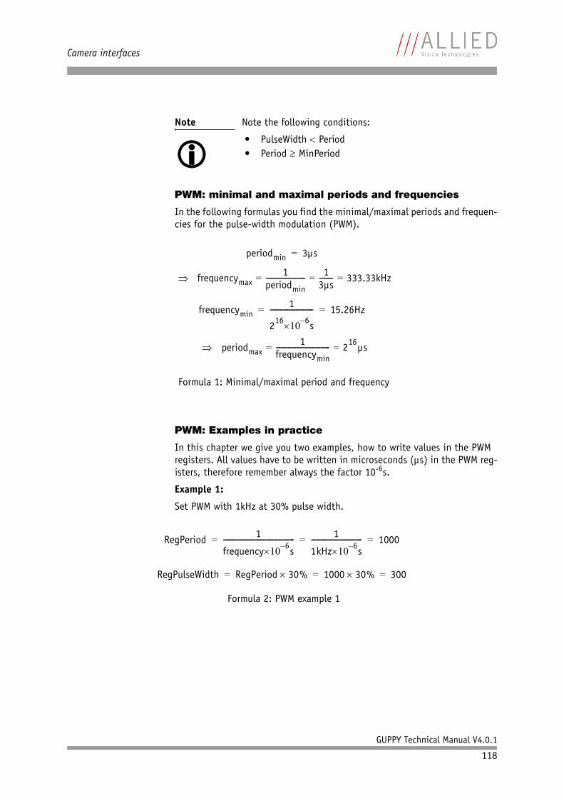
Camera interfaces
GUPPY Technical Manual V4.0.1
118
PWM: minimal and maximal periods and frequencies
In the following formulas you find the minimal/maximal periods and frequen-cies for the pulse-width modulation (PWM).
PWM: Examples in practice
In this chapter we give you two examples, how to write values in the PWM registers. All values have to be written in microseconds (µs) in the PWM reg-isters, therefore remember always the factor 10-6s.
Example 1:
Set PWM with 1kHz at 30% pulse width.
Note Note the following conditions:
• PulseWidth < Period• Period ≥ MinPeriod
Formula 1: Minimal/maximal period and frequency
Formula 2: PWM example 1
periodmin 3µs=
frequencymax1
periodmin----------------------- 1
3µs-------- 333.33kHz= = =⇒
frequencymin1
216 6–×10 s
------------------------- 15.26Hz= =
periodmax1
frequencymin------------------------------- 216µs= =⇒
RegPeriod 1
frequency 6–×10 s----------------------------------------- 1
1kHz 6–×10 s----------------------------- 1000= = =
RegPulseWidth RegPeriod 30%× 1000 30%× 300= = =

Camera interfaces
GUPPY Technical Manual V4.0.1
119
Example 2:
Set PWM with 250 Hz at 12% pulse width.
Formula 3: PWM example 2
RegPeriod 1
frequency 6–×10 s----------------------------------------- 1
250Hz 6–×10 s-------------------------------- 4000= = =
RegPulseWidth RegPeriod 12%× 4000 12%× 480= = =
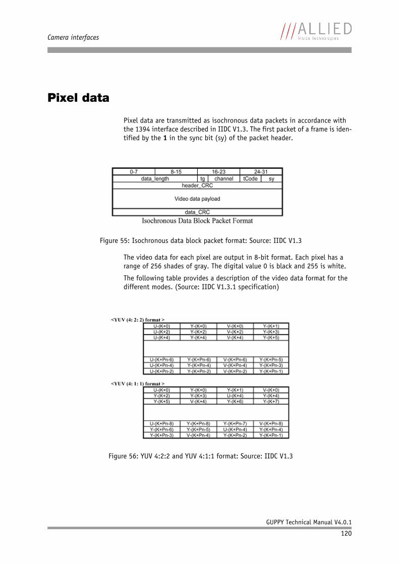
Camera interfaces
GUPPY Technical Manual V4.0.1
120
Pixel data
Pixel data are transmitted as isochronous data packets in accordance with the 1394 interface described in IIDC V1.3. The first packet of a frame is iden-tified by the 1 in the sync bit (sy) of the packet header.
The video data for each pixel are output in 8-bit format. Each pixel has a range of 256 shades of gray. The digital value 0 is black and 255 is white.
The following table provides a description of the video data format for the different modes. (Source: IIDC V1.3.1 specification)
Figure 55: Isochronous data block packet format: Source: IIDC V1.3
Figure 56: YUV 4:2:2 and YUV 4:1:1 format: Source: IIDC V1.3
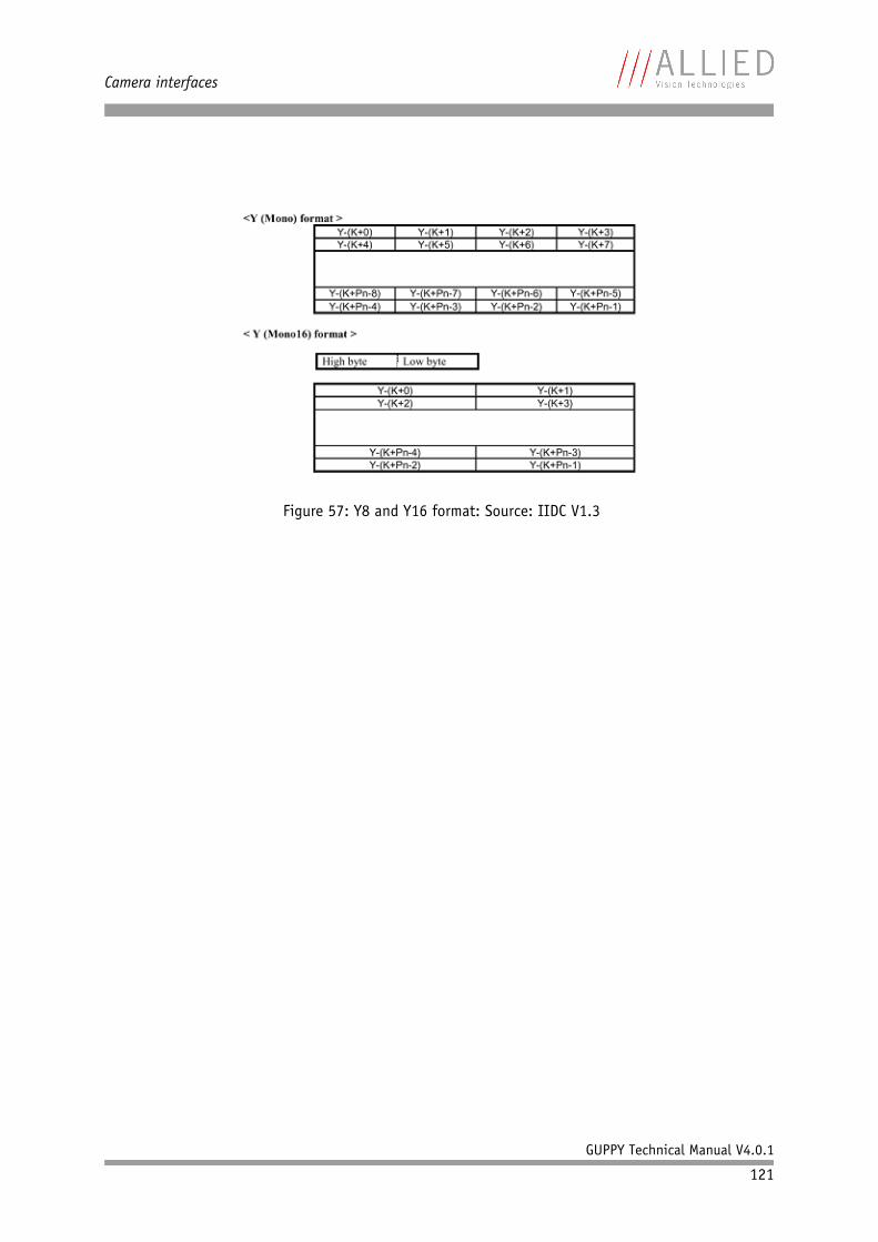
Camera interfaces
GUPPY Technical Manual V4.0.1
121
Figure 57: Y8 and Y16 format: Source: IIDC V1.3
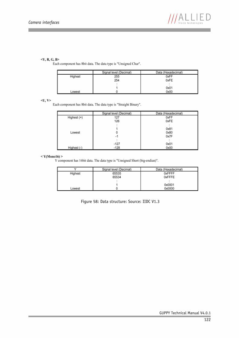
Camera interfaces
GUPPY Technical Manual V4.0.1
122
Figure 58: Data structure: Source: IIDC V1.3
Controlling image capture
GUPPY Technical Manual V4.0.1
123
Controlling image capture
Global shutter
The cameras support the SHUTTER_MODES specified in IIDC V1.3. For all mod-els this shutter is a global shutter; meaning that all pixels are exposed to the light at the same moment and for the same time span.
In continuous modes the shutter is opened shortly before the vertical reset happens, thus acting in a frame-synchronous way.
Combined with an external trigger, it becomes asynchronous in the sense that it occurs whenever the external trigger occurs. Individual images are recorded when an external trigger impulse is present. This ensures that even fast-moving objects can be grabbed with no image lag and with minimal image blur.
The external trigger comes in as a TTL signal through Pin 4 of the cameraI/O connector.
Pipelined global shutter
The CMOS Guppy F-036 (Micron CMOS sensor MT9V022) has a pipelined glo-bal shutter with simultaneous integration and readout.
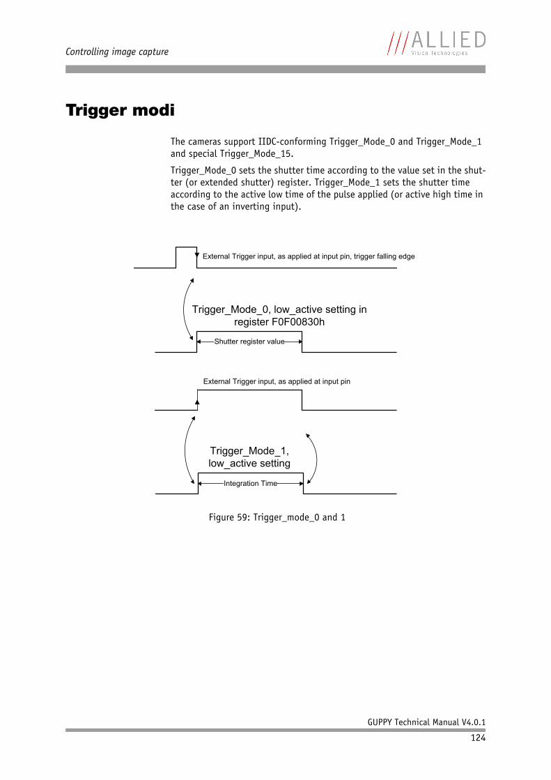
Controlling image capture
GUPPY Technical Manual V4.0.1
124
Trigger modi
The cameras support IIDC-conforming Trigger_Mode_0 and Trigger_Mode_1 and special Trigger_Mode_15.
Trigger_Mode_0 sets the shutter time according to the value set in the shut-ter (or extended shutter) register. Trigger_Mode_1 sets the shutter time according to the active low time of the pulse applied (or active high time in the case of an inverting input).
Figure 59: Trigger_mode_0 and 1
Shutter register value
Integration Time
External Trigger input, as applied at input pin
External Trigger input, as applied at input pin, trigger falling edge
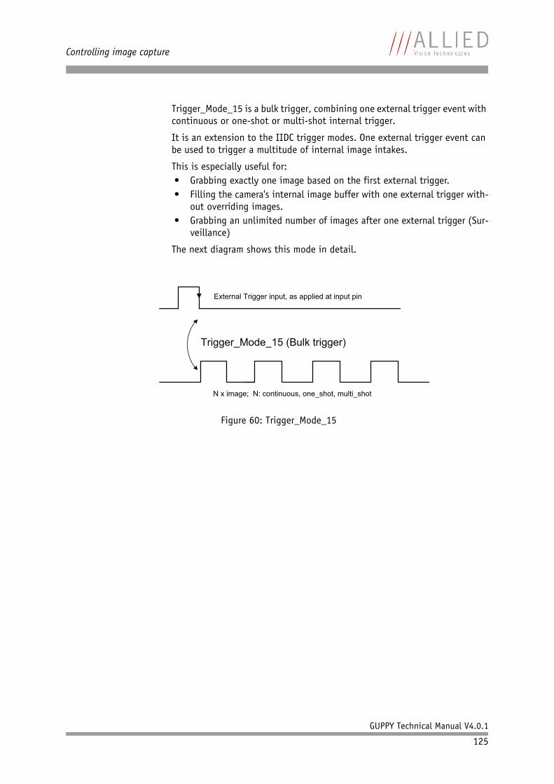
Controlling image capture
GUPPY Technical Manual V4.0.1
125
Trigger_Mode_15 is a bulk trigger, combining one external trigger event with continuous or one-shot or multi-shot internal trigger.
It is an extension to the IIDC trigger modes. One external trigger event can be used to trigger a multitude of internal image intakes.
This is especially useful for:• Grabbing exactly one image based on the first external trigger.• Filling the camera's internal image buffer with one external trigger with-
out overriding images.• Grabbing an unlimited number of images after one external trigger (Sur-
veillance)
The next diagram shows this mode in detail.
Figure 60: Trigger_Mode_15
N x image; N: continuous, one_shot, multi_shot
External Trigger input, as applied at input pin
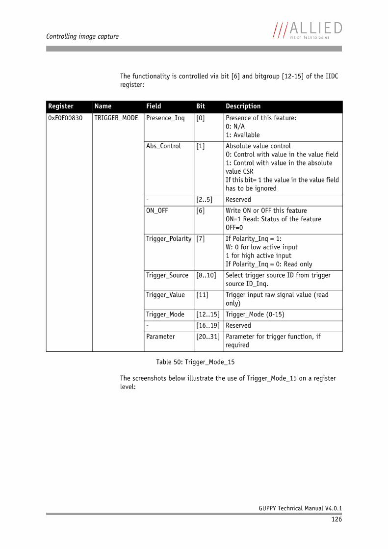
Controlling image capture
GUPPY Technical Manual V4.0.1
126
The functionality is controlled via bit [6] and bitgroup [12-15] of the IIDC register:
The screenshots below illustrate the use of Trigger_Mode_15 on a register level:
Register Name Field Bit Description
0xF0F00830 TRIGGER_MODE Presence_Inq [0] Presence of this feature:0: N/A1: Available
Abs_Control [1] Absolute value controlO: Control with value in the value field 1: Control with value in the absolute value CSRIf this bit= 1 the value in the value field has to be ignored
- [2..5] Reserved
ON_OFF [6] Write ON or OFF this featureON=1 Read: Status of the featureOFF=0
Trigger_Polarity [7] If Polarity_Inq = 1:W: 0 for low active input1 for high active inputIf Polarity_Inq = 0: Read only
Trigger_Source [8..10] Select trigger source ID from trigger source ID_Inq.
Trigger_Value [11] Trigger input raw signal value (read only)
Trigger_Mode [12..15] Trigger_Mode (0-15)
- [16..19] Reserved
Parameter [20..31] Parameter for trigger function, if required
Table 50: Trigger_Mode_15
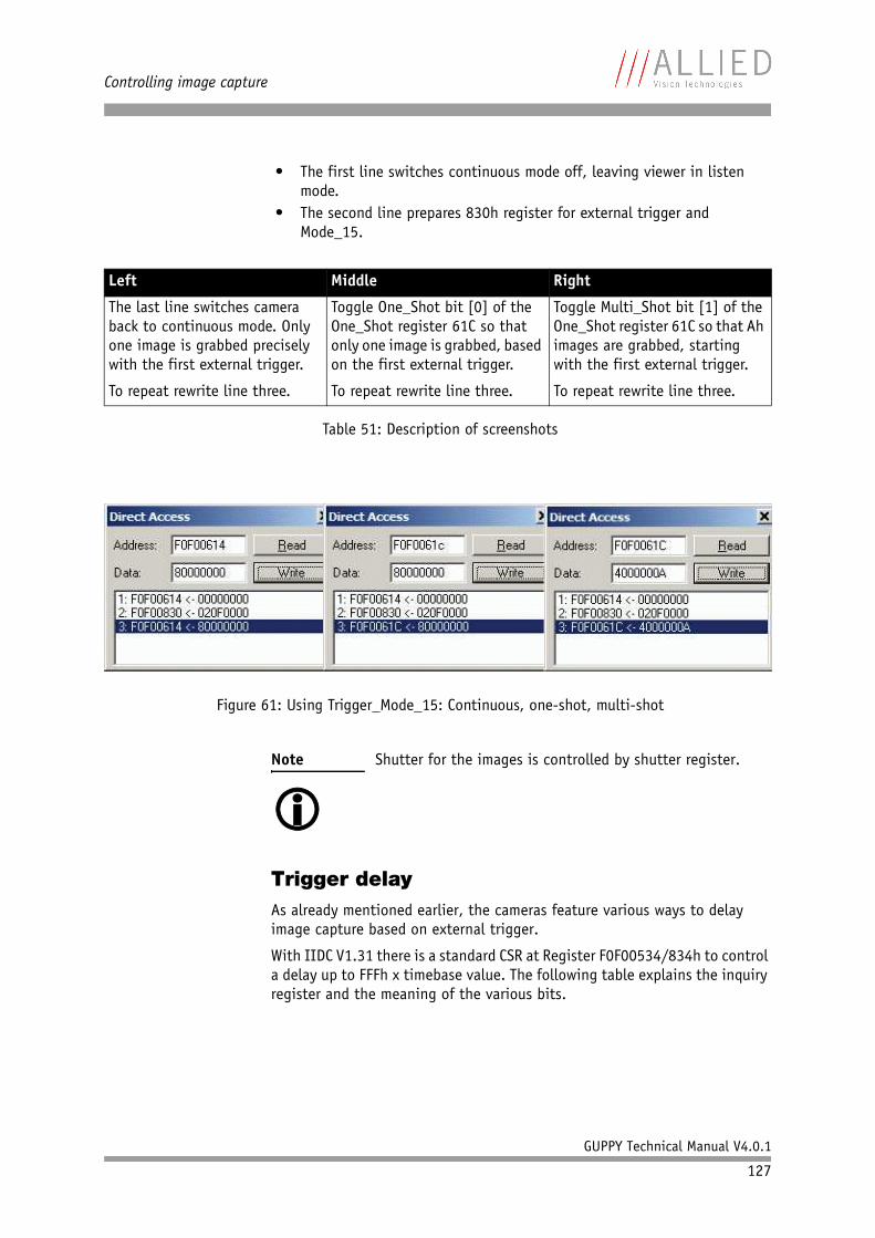
Controlling image capture
GUPPY Technical Manual V4.0.1
127
• The first line switches continuous mode off, leaving viewer in listen mode.
• The second line prepares 830h register for external trigger and Mode_15.
Trigger delayAs already mentioned earlier, the cameras feature various ways to delay image capture based on external trigger.
With IIDC V1.31 there is a standard CSR at Register F0F00534/834h to control a delay up to FFFh x timebase value. The following table explains the inquiry register and the meaning of the various bits.
Left Middle Right
The last line switches camera back to continuous mode. Only one image is grabbed precisely with the first external trigger.
To repeat rewrite line three.
Toggle One_Shot bit [0] of the One_Shot register 61C so that only one image is grabbed, based on the first external trigger.
To repeat rewrite line three.
Toggle Multi_Shot bit [1] of the One_Shot register 61C so that Ah images are grabbed, starting with the first external trigger.
To repeat rewrite line three.
Table 51: Description of screenshots
Figure 61: Using Trigger_Mode_15: Continuous, one-shot, multi-shot
Note Shutter for the images is controlled by shutter register.
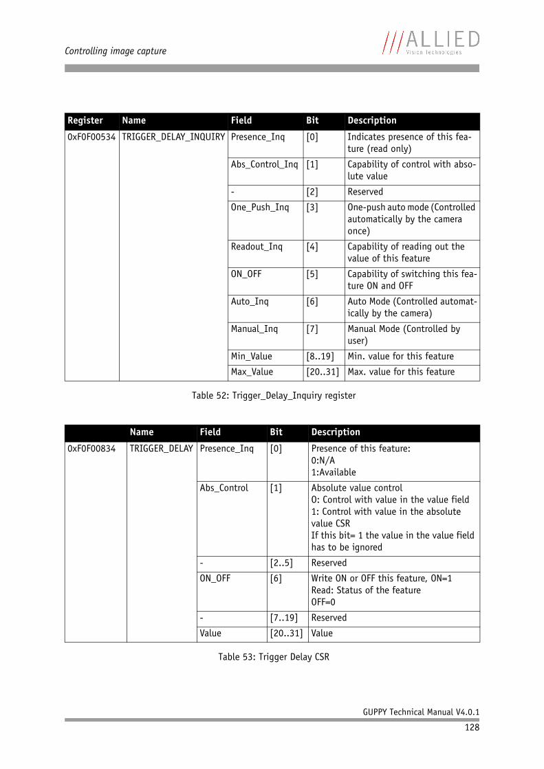
Controlling image capture
GUPPY Technical Manual V4.0.1
128
Register Name Field Bit Description
0xF0F00534 TRIGGER_DELAY_INQUIRY Presence_Inq [0] Indicates presence of this fea-ture (read only)
Abs_Control_Inq [1] Capability of control with abso-lute value
- [2] Reserved
One_Push_Inq [3] One-push auto mode (Controlled automatically by the camera once)
Readout_Inq [4] Capability of reading out the value of this feature
ON_OFF [5] Capability of switching this fea-ture ON and OFF
Auto_Inq [6] Auto Mode (Controlled automat-ically by the camera)
Manual_Inq [7] Manual Mode (Controlled by user)
Min_Value [8..19] Min. value for this feature
Max_Value [20..31] Max. value for this feature
Table 52: Trigger_Delay_Inquiry register
Name Field Bit Description
0xF0F00834 TRIGGER_DELAY Presence_Inq [0] Presence of this feature:0:N/A1:Available
Abs_Control [1] Absolute value controlO: Control with value in the value field1: Control with value in the absolute value CSRIf this bit= 1 the value in the value field has to be ignored
- [2..5] Reserved
ON_OFF [6] Write ON or OFF this feature, ON=1Read: Status of the featureOFF=0
- [7..19] Reserved
Value [20..31] Value
Table 53: Trigger Delay CSR
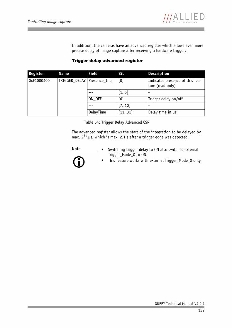
Controlling image capture
GUPPY Technical Manual V4.0.1
129
In addition, the cameras have an advanced register which allows even more precise delay of image capture after receiving a hardware trigger.
Trigger delay advanced register
The advanced register allows the start of the integration to be delayed by max. 221 µs, which is max. 2.1 s after a trigger edge was detected.
Register Name Field Bit Description
0xF1000400 TRIGGER_DELAY Presence_Inq [0] Indicates presence of this fea-ture (read only)
--- [1..5] -
ON_OFF [6] Trigger delay on/off
--- [7..10] -
DelayTime [11..31] Delay time in µs
Table 54: Trigger Delay Advanced CSR
Note • Switching trigger delay to ON also switches external Trigger_Mode_0 to ON.
• This feature works with external Trigger_Mode_0 only.
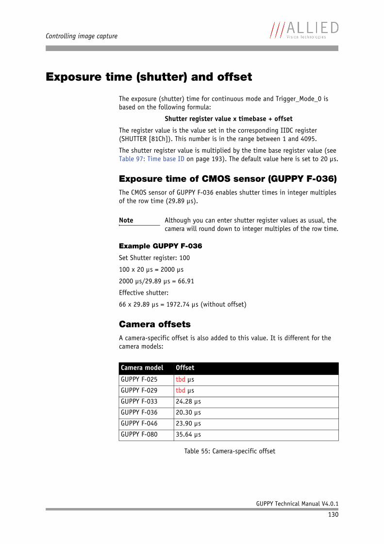
Controlling image capture
GUPPY Technical Manual V4.0.1
130
Exposure time (shutter) and offset
The exposure (shutter) time for continuous mode and Trigger_Mode_0 is based on the following formula:
Shutter register value x timebase + offset
The register value is the value set in the corresponding IIDC register (SHUTTER [81Ch]). This number is in the range between 1 and 4095.
The shutter register value is multiplied by the time base register value (see Table 97: Time base ID on page 193). The default value here is set to 20 µs.
Exposure time of CMOS sensor (GUPPY F-036)The CMOS sensor of GUPPY F-036 enables shutter times in integer multiples of the row time (29.89 µs).
Example GUPPY F-036
Set Shutter register: 100
100 x 20 µs = 2000 µs
2000 µs/29.89 µs = 66.91
Effective shutter:
66 x 29.89 µs = 1972.74 µs (without offset)
Camera offsetsA camera-specific offset is also added to this value. It is different for the camera models:
Note Although you can enter shutter register values as usual, the camera will round down to integer multiples of the row time.
Camera model Offset
GUPPY F-025 tbd µs
GUPPY F-029 tbd µs
GUPPY F-033 24.28 µs
GUPPY F-036 20.30 µs
GUPPY F-046 23.90 µs
GUPPY F-080 35.64 µs
Table 55: Camera-specific offset
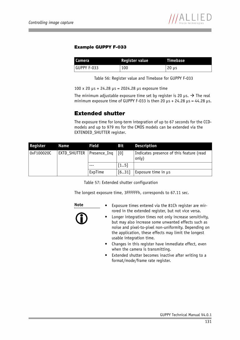
Controlling image capture
GUPPY Technical Manual V4.0.1
131
Example GUPPY F-033
100 x 20 µs + 24.28 µs = 2024.28 µs exposure time
The minimum adjustable exposure time set by register is 20 µs. The real minimum exposure time of GUPPY F-033 is then 20 µs + 24.28 µs = 44.28 µs.
Extended shutterThe exposure time for long-term integration of up to 67 seconds for the CCD-models and up to 979 ms for the CMOS models can be extended via the EXTENDED_SHUTTER register.
The longest exposure time, 3FFFFFFh, corresponds to 67.11 sec.
Camera Register value Timebase
GUPPY F-033 100 20 µs
Table 56: Register value and Timebase for GUPPY F-033
Register Name Field Bit Description
0xF100020C EXTD_SHUTTER Presence_Inq [0] Indicates presence of this feature (read only)
--- [1..5]
ExpTime [6..31] Exposure time in µs
Table 57: Extended shutter configuration
Note • Exposure times entered via the 81Ch register are mir-rored in the extended register, but not vice versa.
• Longer integration times not only increase sensitivity, but may also increase some unwanted effects such as noise and pixel-to-pixel non-uniformity. Depending on the application, these effects may limit the longest usable integration time.
• Changes in this register have immediate effect, even when the camera is transmitting.
• Extended shutter becomes inactive after writing to a format/mode/frame rate register.
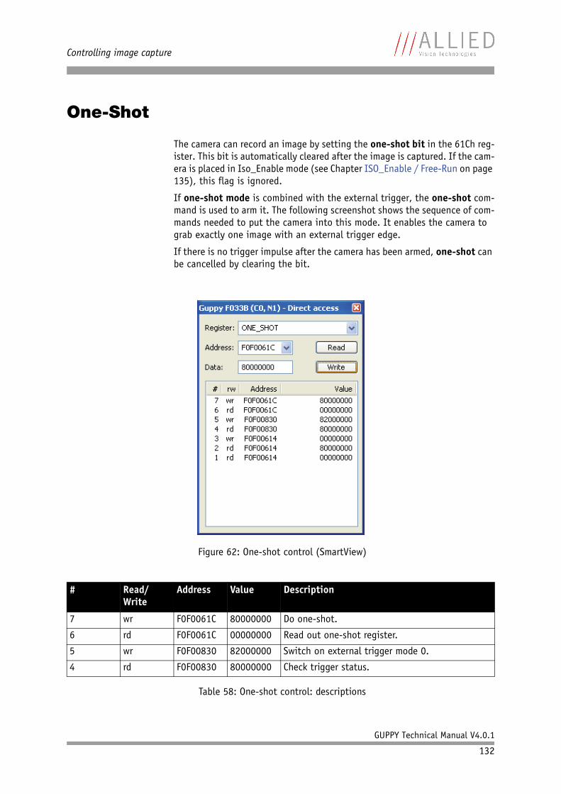
Controlling image capture
GUPPY Technical Manual V4.0.1
132
One-Shot
The camera can record an image by setting the one-shot bit in the 61Ch reg-ister. This bit is automatically cleared after the image is captured. If the cam-era is placed in Iso_Enable mode (see Chapter ISO_Enable / Free-Run on page 135), this flag is ignored.
If one-shot mode is combined with the external trigger, the one-shot com-mand is used to arm it. The following screenshot shows the sequence of com-mands needed to put the camera into this mode. It enables the camera to grab exactly one image with an external trigger edge.
If there is no trigger impulse after the camera has been armed, one-shot can be cancelled by clearing the bit.
Figure 62: One-shot control (SmartView)
# Read/Write
Address Value Description
7 wr F0F0061C 80000000 Do one-shot.
6 rd F0F0061C 00000000 Read out one-shot register.
5 wr F0F00830 82000000 Switch on external trigger mode 0.
4 rd F0F00830 80000000 Check trigger status.
Table 58: One-shot control: descriptions
Controlling image capture
GUPPY Technical Manual V4.0.1
133
One-shot command on the bus to start of exposureThe following sections describe the time response of the camera using a sin-gle frame (one-shot) command. As set out in the IIDC specification, this is a software command that causes the camera to record and transmit a single frame.
The following values apply only when the camera is idle and ready for use. Full resolution must also be set.
Microcontroller-Sync is an internal signal. It is generated by the microcon-troller to initiate a trigger. This can either be a direct trigger or a release for ExSync if the camera is externally triggered.
End of exposure to first packet on the busAfter the exposure, the CCD or CMOS sensor is read out; some data is written into a small FiFo buffer before being transmitted to the bus.
The time from the end of exposure to the start of transport on the bus is:
500 µs ± 62.5 µs
This time 'jitters' with the cycle time of the bus (125 µs).
3 wr F0F00614 00000000 Stop Free-run.
2 rd F0F00614 80000000 Check Iso_Enable mode ( Free-run).
1 rd F0F00614 00000000 This line is produced by SmartView.
Feature Value
One-shot Microcontroller-Sync ≤ 250 µs (processing time in the microcontroller)
µC-Sync/ExSync Integration-Start 8 µs
Table 59: Values for one-shot
# Read/Write
Address Value Description
Table 58: One-shot control: descriptions
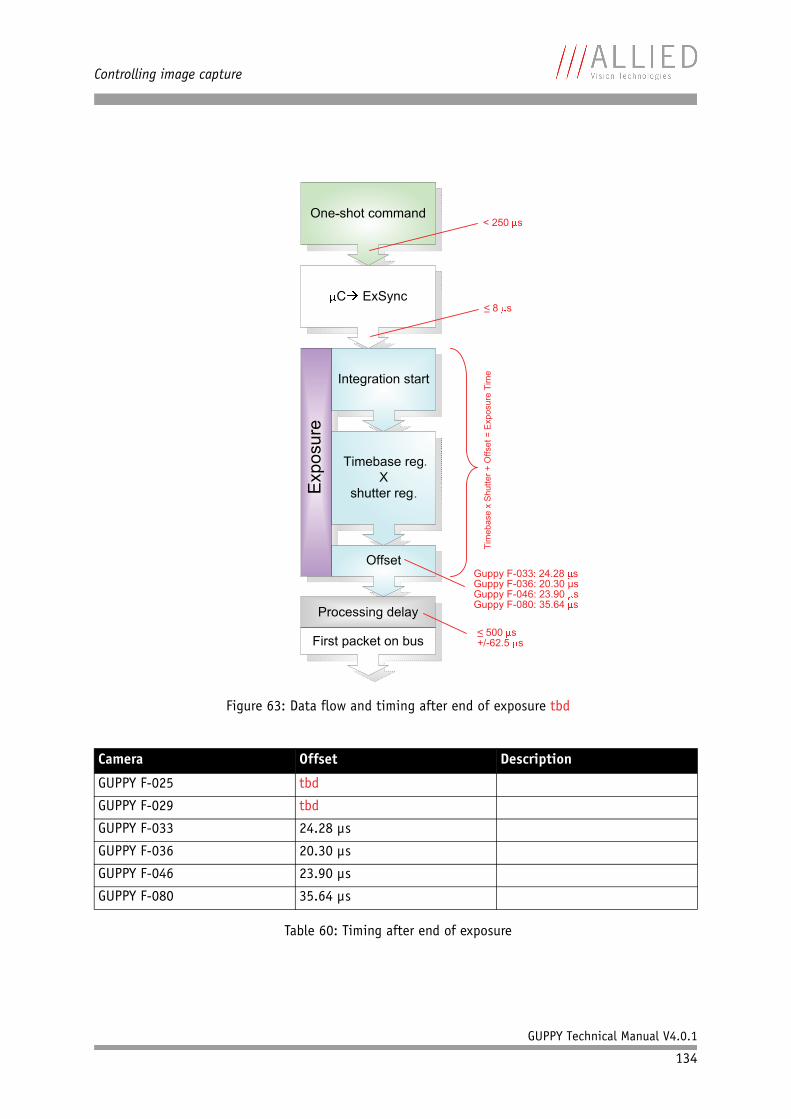
Controlling image capture
GUPPY Technical Manual V4.0.1
134
Figure 63: Data flow and timing after end of exposure tbd
Camera Offset Description
GUPPY F-025 tbd
GUPPY F-029 tbd
GUPPY F-033 24.28 µs
GUPPY F-036 20.30 µs
GUPPY F-046 23.90 µs
GUPPY F-080 35.64 µs
Table 60: Timing after end of exposure
< 250 s
8 s
Guppy F-033 24.28 sGuppy F-036: 20.30 µsGuppy F-046: 23.90 sGuppy F-080: 35.64 s
Tim
ebase x
Shutter
+ O
ffset
= E
xposure
Tim
e
500 s+/-62.5 s
Controlling image capture
GUPPY Technical Manual V4.0.1
135
Multi-shot
Setting multi-shot and entering a quantity of images in Count_Number in the 61Ch register enables the camera to record a specified number of images.
The number is indicated in bits 16 to 31. If the camera is put into Iso_Enable mode (see Chapter ISO_Enable / Free-Run on page 135), this flag is ignored and deleted automatically once all the images have been recorded.
If multi-shot mode is activated and the images have not yet all been cap-tured, it can be cancelled by resetting the flag. The same result can be achieved by setting the number of images to 0.
Multi-shot can also be combined with the external trigger in order to grab a certain number of images based on an external trigger.
ISO_Enable / Free-Run
Setting the MSB (bit 0) in the 614h register (ISO_ENA) puts the camera into ISO_Enable mode or Continuous_Shot. The camera captures an infinite series of images. This operation can be quit by deleting the 0 bit.
Asynchronous broadcast
The camera accepts asynchronous broadcasts. This involves asynchronous write requests that use node number 63 as the target node with no acknowl-edge.
This makes it possible for all cameras on a bus to be triggered by software simultaneously - e.g. by broadcasting a one-shot. All cameras receive the one-shot command in the same IEEE 1394 bus cycle. This creates uncertainty for all cameras in the range of 125 µs.
Inter-camera latency is described in Chapter Jitter at start of exposure on page 136.
The following screenshot shows an example of broadcast commands sent with the Firedemo example of FirePackage (version 1V51 or newer):
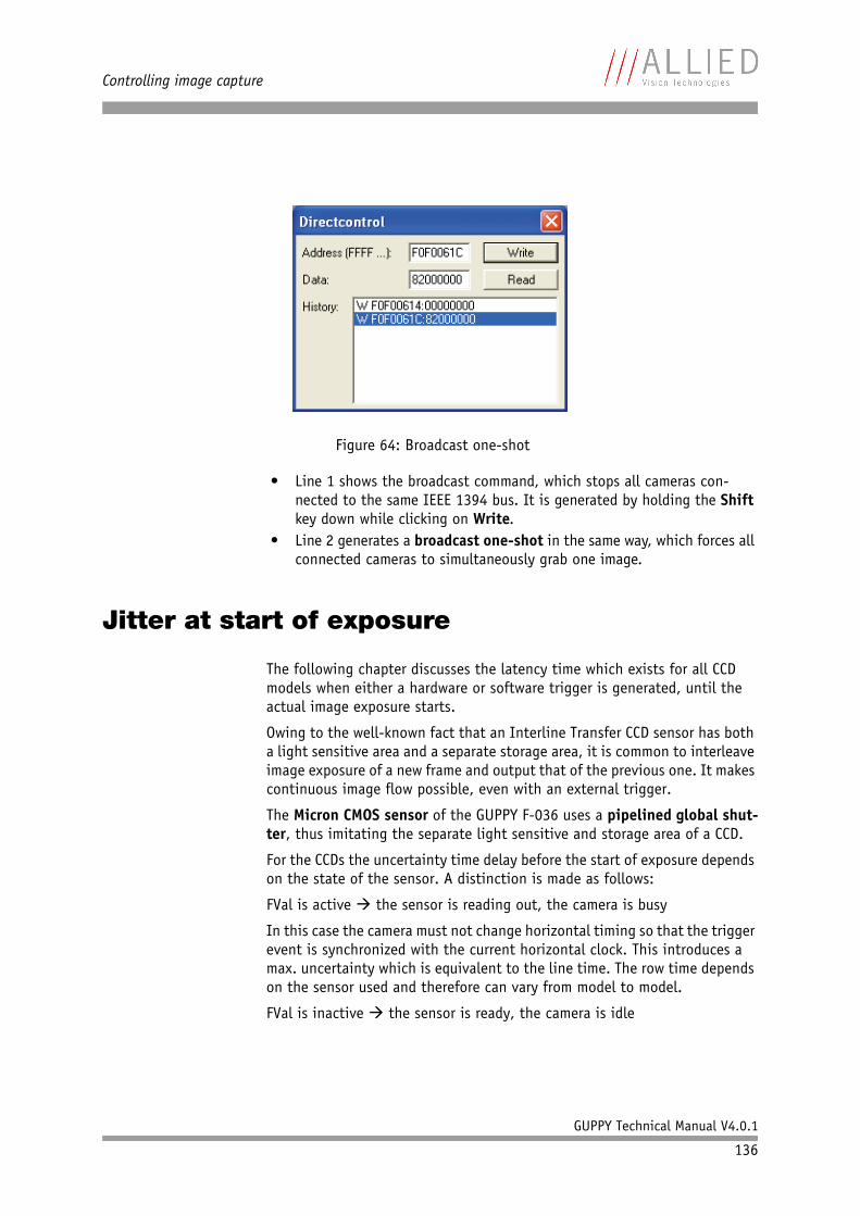
Controlling image capture
GUPPY Technical Manual V4.0.1
136
• Line 1 shows the broadcast command, which stops all cameras con-nected to the same IEEE 1394 bus. It is generated by holding the Shift key down while clicking on Write.
• Line 2 generates a broadcast one-shot in the same way, which forces all connected cameras to simultaneously grab one image.
Jitter at start of exposure
The following chapter discusses the latency time which exists for all CCD models when either a hardware or software trigger is generated, until the actual image exposure starts.
Owing to the well-known fact that an Interline Transfer CCD sensor has both a light sensitive area and a separate storage area, it is common to interleave image exposure of a new frame and output that of the previous one. It makes continuous image flow possible, even with an external trigger.
The Micron CMOS sensor of the GUPPY F-036 uses a pipelined global shut-ter, thus imitating the separate light sensitive and storage area of a CCD.
For the CCDs the uncertainty time delay before the start of exposure depends on the state of the sensor. A distinction is made as follows:
FVal is active the sensor is reading out, the camera is busy
In this case the camera must not change horizontal timing so that the trigger event is synchronized with the current horizontal clock. This introduces a max. uncertainty which is equivalent to the line time. The row time depends on the sensor used and therefore can vary from model to model.
FVal is inactive the sensor is ready, the camera is idle
Figure 64: Broadcast one-shot
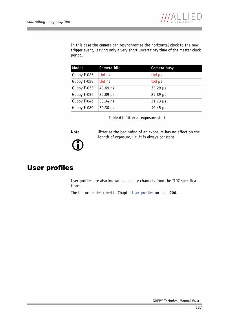
Controlling image capture
GUPPY Technical Manual V4.0.1
137
In this case the camera can resynchronize the horizontal clock to the new trigger event, leaving only a very short uncertainty time of the master clock period.
User profiles
User profiles are also known as memory channels from the IIDC specifica-tions.
The feature is described in Chapter User profiles on page 206.
Model Camera idle Camera busy
Guppy F-025 tbd ns tbd µs
Guppy F-029 tbd ns tbd µs
Guppy F-033 40.69 ns 32.29 µs
Guppy F-036 29.89 µs 29.89 µs
Guppy F-046 33.34 ns 31.73 µs
Guppy F-080 30.30 ns 40.45 µs
Table 61: Jitter at exposure start
Note Jitter at the beginning of an exposure has no effect on the length of exposure, i.e. it is always constant.
Video formats, modes and bandwidth
GUPPY Technical Manual V4.0.1
138
Video formats, modes and bandwidth
The different GUPPY models support different video formats, modes and frame rates.
These formats and modes are standardized in the IIDC (formerly DCAM) spec-ification.
Resolutions smaller than the generic sensor resolution are generated from the center of the sensor and without binning.
GUPPY F-025B / GUPPY F-025C
tbd
GUPPY F-029B / GUPPY F-029C
tbd
Note • The maximum frame rates can only be achieved with shutter settings lower than 1/framerate. This means that with default shutter time of 40 ms, a camera will not achieve frame rates higher than 25 frames/s. In order to achieve higher frame rates, please reduce the shutter time proportionally.
• Tables assume that bus speed is 400 Mbit/s. With lower bus speeds (e.g. 200 or 100 Mbit/s) not all frame rates may be achieved.
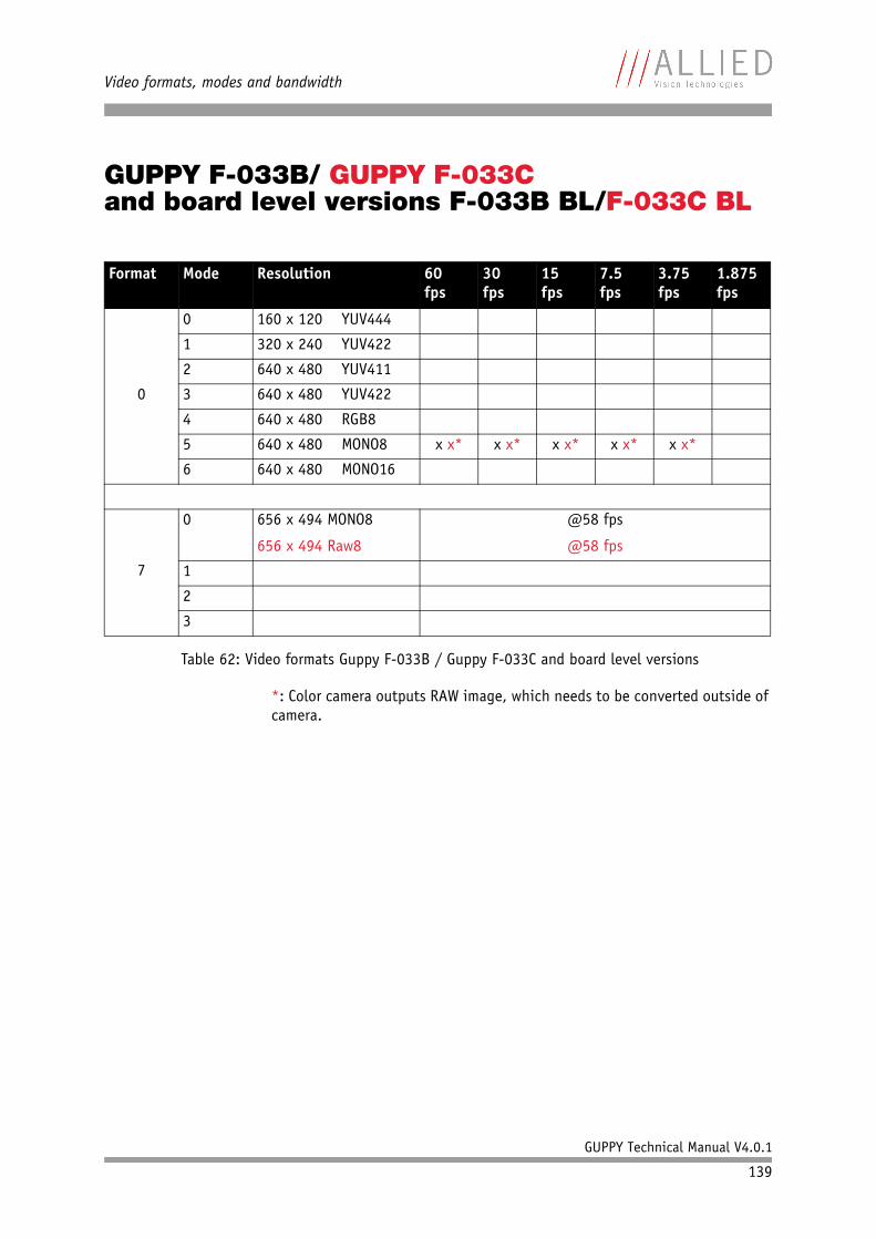
Video formats, modes and bandwidth
GUPPY Technical Manual V4.0.1
139
GUPPY F-033B/ GUPPY F-033Cand board level versions F-033B BL/F-033C BL
*: Color camera outputs RAW image, which needs to be converted outside of camera.
Format Mode Resolution 60 fps
30 fps
15 fps
7.5 fps
3.75 fps
1.875 fps
0
0 160 x 120 YUV444
1 320 x 240 YUV422
2 640 x 480 YUV411
3 640 x 480 YUV422
4 640 x 480 RGB8
5 640 x 480 MONO8 x x* x x* x x* x x* x x*
6 640 x 480 MONO16
7
0 656 x 494 MONO8
656 x 494 Raw8
@58 fps
@58 fps
1
2
3
Table 62: Video formats Guppy F-033B / Guppy F-033C and board level versions
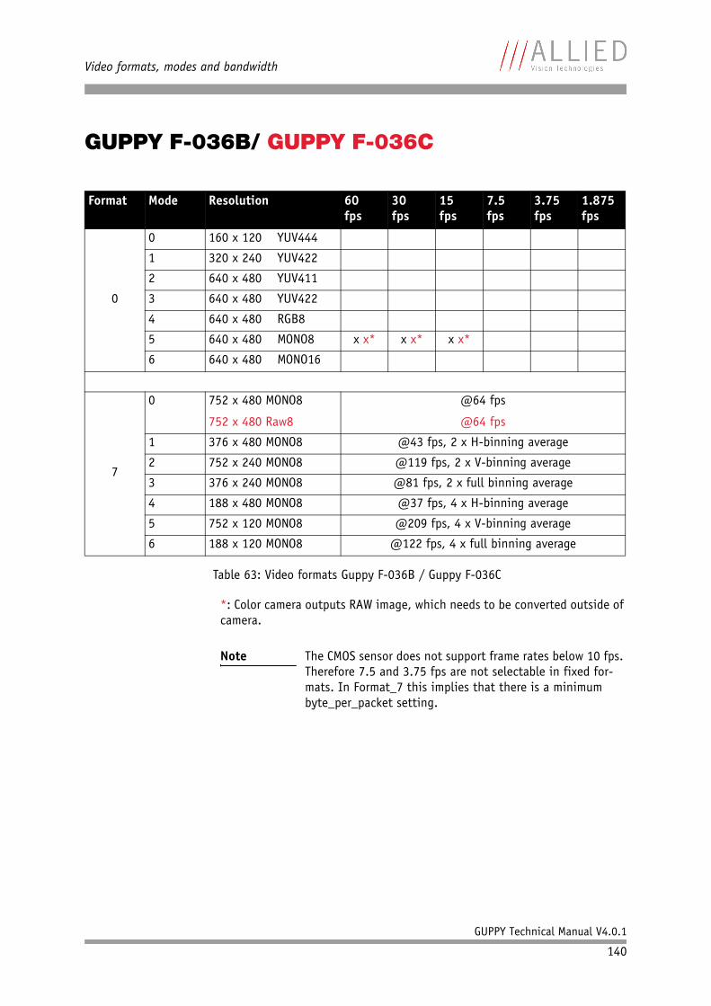
Video formats, modes and bandwidth
GUPPY Technical Manual V4.0.1
140
GUPPY F-036B/ GUPPY F-036C
*: Color camera outputs RAW image, which needs to be converted outside of camera.
Format Mode Resolution 60 fps
30 fps
15 fps
7.5 fps
3.75 fps
1.875 fps
0
0 160 x 120 YUV444
1 320 x 240 YUV422
2 640 x 480 YUV411
3 640 x 480 YUV422
4 640 x 480 RGB8
5 640 x 480 MONO8 x x* x x* x x*
6 640 x 480 MONO16
7
0 752 x 480 MONO8
752 x 480 Raw8
@64 fps
@64 fps
1 376 x 480 MONO8 @43 fps, 2 x H-binning average
2 752 x 240 MONO8 @119 fps, 2 x V-binning average
3 376 x 240 MONO8 @81 fps, 2 x full binning average
4 188 x 480 MONO8 @37 fps, 4 x H-binning average
5 752 x 120 MONO8 @209 fps, 4 x V-binning average
6 188 x 120 MONO8 @122 fps, 4 x full binning average
Table 63: Video formats Guppy F-036B / Guppy F-036C
Note The CMOS sensor does not support frame rates below 10 fps. Therefore 7.5 and 3.75 fps are not selectable in fixed for-mats. In Format_7 this implies that there is a minimum byte_per_packet setting.
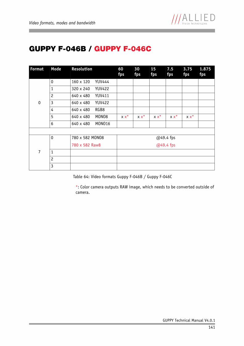
Video formats, modes and bandwidth
GUPPY Technical Manual V4.0.1
141
GUPPY F-046B / GUPPY F-046C
*: Color camera outputs RAW image, which needs to be converted outside of camera.
Format Mode Resolution 60 fps
30 fps
15 fps
7.5 fps
3.75 fps
1.875 fps
0
0 160 x 120 YUV444
1 320 x 240 YUV422
2 640 x 480 YUV411
3 640 x 480 YUV422
4 640 x 480 RGB8
5 640 x 480 MONO8 x x* x x* x x* x x* x x*
6 640 x 480 MONO16
7
0 780 x 582 MONO8
780 x 582 Raw8
@49.4 fps
@49.4 fps
1
2
3
Table 64: Video formats Guppy F-046B / Guppy F-046C
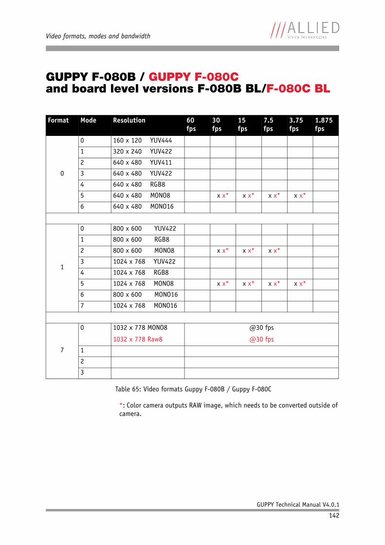
Video formats, modes and bandwidth
GUPPY Technical Manual V4.0.1
142
GUPPY F-080B / GUPPY F-080Cand board level versions F-080B BL/F-080C BL
*: Color camera outputs RAW image, which needs to be converted outside of camera.
Format Mode Resolution 60 fps
30 fps
15 fps
7.5 fps
3.75 fps
1.875 fps
0
0 160 x 120 YUV444
1 320 x 240 YUV422
2 640 x 480 YUV411
3 640 x 480 YUV422
4 640 x 480 RGB8
5 640 x 480 MONO8 x x* x x* x x* x x*
6 640 x 480 MONO16
1
0 800 x 600 YUV422
1 800 x 600 RGB8
2 800 x 600 MONO8 x x* x x* x x*
3 1024 x 768 YUV422
4 1024 x 768 RGB8
5 1024 x 768 MONO8 x x* x x* x x* x x*
6 800 x 600 MONO16
7 1024 x 768 MONO16
7
0 1032 x 778 MONO8
1032 x 778 Raw8
@30 fps
@30 fps
1
2
3
Table 65: Video formats Guppy F-080B / Guppy F-080C
Video formats, modes and bandwidth
GUPPY Technical Manual V4.0.1
143
Area of interest (AOI)
The cameras image sensor has a defined resolution. This indicates the maxi-mum number of lines and pixels per line that the recorded image may have.
However, often only a certain section of the entire image is of interest. The amount of data to be transferred can be decreased by limiting the image to a section when reading it out from the camera. At a lower vertical resolution the sensor can be read out faster and thus the frame rate is increased.
While the size of the image read out for most other video formats and modes is fixed by the IIDC specification, thereby determining the highest possible frame rate, in Format_7 mode the user can set the upper left corner and width and height of the section (Area of Interest = AOI) he is interested in to determine the size and thus the highest possible frame rate.
Setting the AOI is done in the IMAGE_POSITION and IMAGE_SIZE registers.
Note The setting of AOIs is supported only in video Format_7.
Note Attention should be paid to the increments entered in the UNIT_SIZE_INQ and UNIT_POSITION_INQ registers when con-figuring IMAGE_POSITION and IMAGE_SIZE.
IMAGE_POSITION and IMAGE_SIZE contain the respective bits values for the column and line of the upper left corner and values for the width and height.
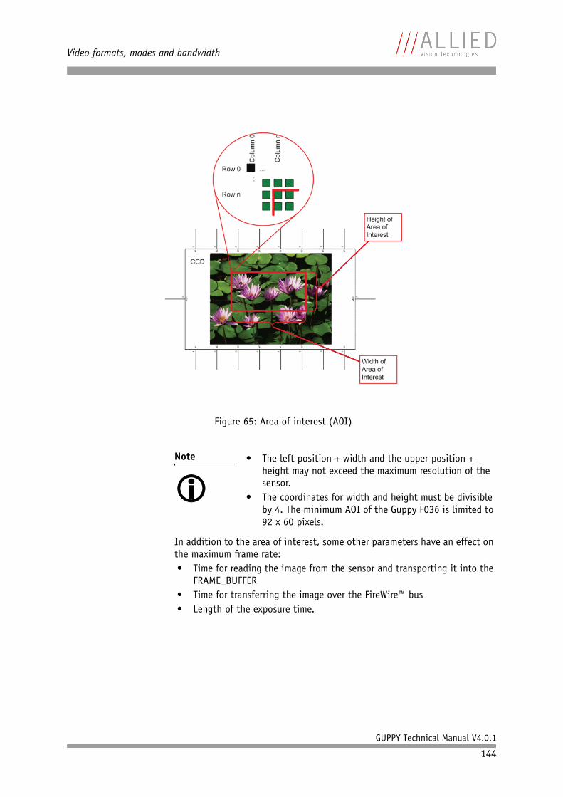
Video formats, modes and bandwidth
GUPPY Technical Manual V4.0.1
144
In addition to the area of interest, some other parameters have an effect on the maximum frame rate:• Time for reading the image from the sensor and transporting it into the
FRAME_BUFFER• Time for transferring the image over the FireWire™ bus• Length of the exposure time.
Figure 65: Area of interest (AOI)
Note • The left position + width and the upper position + height may not exceed the maximum resolution of the sensor.
• The coordinates for width and height must be divisible by 4. The minimum AOI of the Guppy F036 is limited to 92 x 60 pixels.
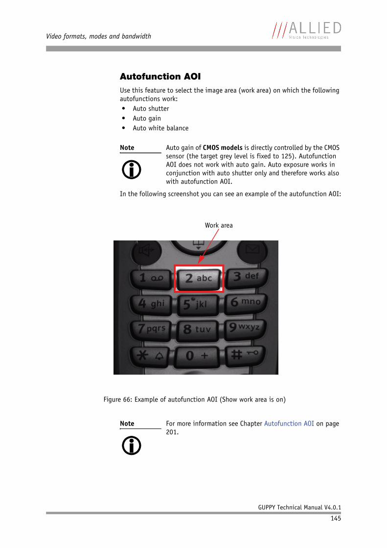
Video formats, modes and bandwidth
GUPPY Technical Manual V4.0.1
145
Autofunction AOIUse this feature to select the image area (work area) on which the following autofunctions work:• Auto shutter• Auto gain• Auto white balance
In the following screenshot you can see an example of the autofunction AOI:
Note Auto gain of CMOS models is directly controlled by the CMOS sensor (the target grey level is fixed to 125). Autofunction AOI does not work with auto gain. Auto exposure works in conjunction with auto shutter only and therefore works also with autofunction AOI.
Figure 66: Example of autofunction AOI (Show work area is on)
Note For more information see Chapter Autofunction AOI on page 201.
Work area
Video formats, modes and bandwidth
GUPPY Technical Manual V4.0.1
146
Frame rates
An IEEE 1394 camera requires bandwidth to transport images.
The IEEE 1394a bus has very large bandwidth of at least 32 MB/s for trans-ferring (isochronously) image data. Per cycle up to 4096 bytes (or around 1000 quadlets = 4 bytes@ 400 Mbit/s) can thus be transmitted.
Depending on the video format settings and the configured frame rate, the camera requires a certain percentage of maximum available bandwidth. Clearly, the bigger the image and the higher the frame rate, the more data requires transmission.
The following tables indicate the volume of data in various formats and modes to be sent within one cycle (125 µs) at 400 Mbit/s of bandwidth.
The tables are divided into three formats; F_0 up to VGA, F_1 up to XGA, and F_2 up to UXGA.
They enable you to calculate the required bandwidth and to ascertain the number of cameras that can be operated independently on a bus and in which mode.
The frame rates in video modes 0 to 2 are specified, and settings are fixed by IIDC V1.3.
In video Format_7 frame rates are no longer fixed.
GUPPY F-025tbd
GUPPY F-029tbd
Note • If the cameras are operated with an external trigger the maximum trigger frequency may not exceed the highest continuous frame rate, thus preventing frames from being dropped or corrupted.
• IEEE 1394 adapter cards with PCILynx™ chipsets have a limit of 4000 bytes per cycle.
Note Different values apply for the different sensors.
Frame rates may be further limited by longer shutter times and/or bandwidth limitation from the IEEE 1394 bus.
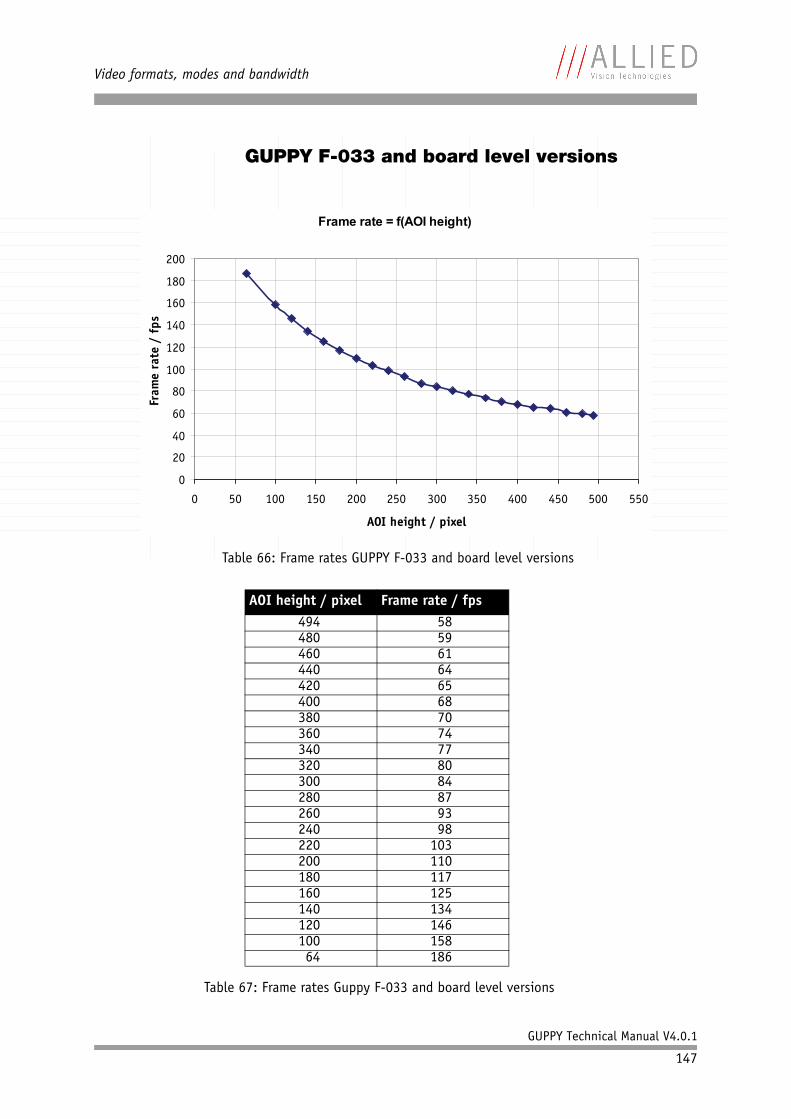
Video formats, modes and bandwidth
GUPPY Technical Manual V4.0.1
147
GUPPY F-033 and board level versions
Table 66: Frame rates GUPPY F-033 and board level versions
AOI height / pixel Frame rate / fps494 58480 59460 61440 64420 65400 68380 70360 74340 77320 80300 84280 87260 93240 98220 103200 110180 117160 125140 134120 146100 15864 186
Table 67: Frame rates Guppy F-033 and board level versions
Frame rate = f(AOI height)
0
20
40
60
80
100
120
140
160
180
200
0 50 100 150 200 250 300 350 400 450 500 550
AOI height / pixel
Fram
e ra
te /
fps
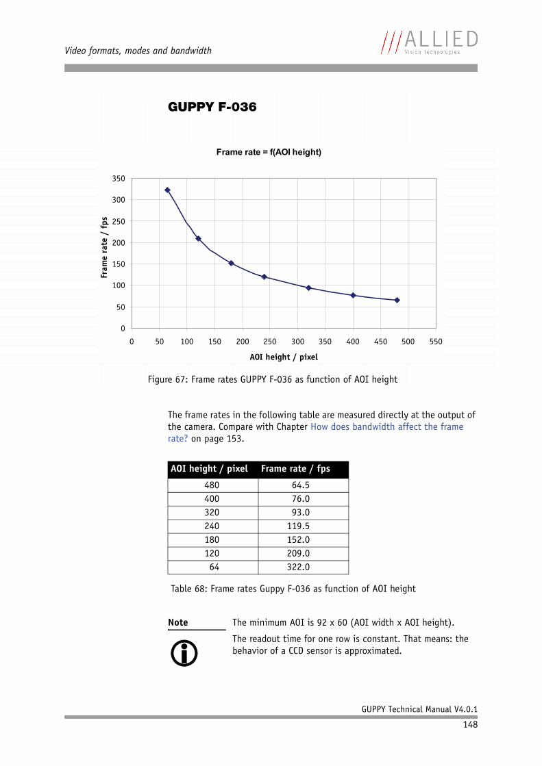
Video formats, modes and bandwidth
GUPPY Technical Manual V4.0.1
148
GUPPY F-036
The frame rates in the following table are measured directly at the output of the camera. Compare with Chapter How does bandwidth affect the frame rate? on page 153.
Figure 67: Frame rates GUPPY F-036 as function of AOI height
AOI height / pixel Frame rate / fps
480 64.5400 76.0320 93.0240 119.5180 152.0120 209.064 322.0
Table 68: Frame rates Guppy F-036 as function of AOI height
Note The minimum AOI is 92 x 60 (AOI width x AOI height).
The readout time for one row is constant. That means: the behavior of a CCD sensor is approximated.
Frame rate = f(AOI height)
0
50
100
150
200
250
300
350
0 50 100 150 200 250 300 350 400 450 500 550
AOI height / pixel
Fram
e ra
te /
fps
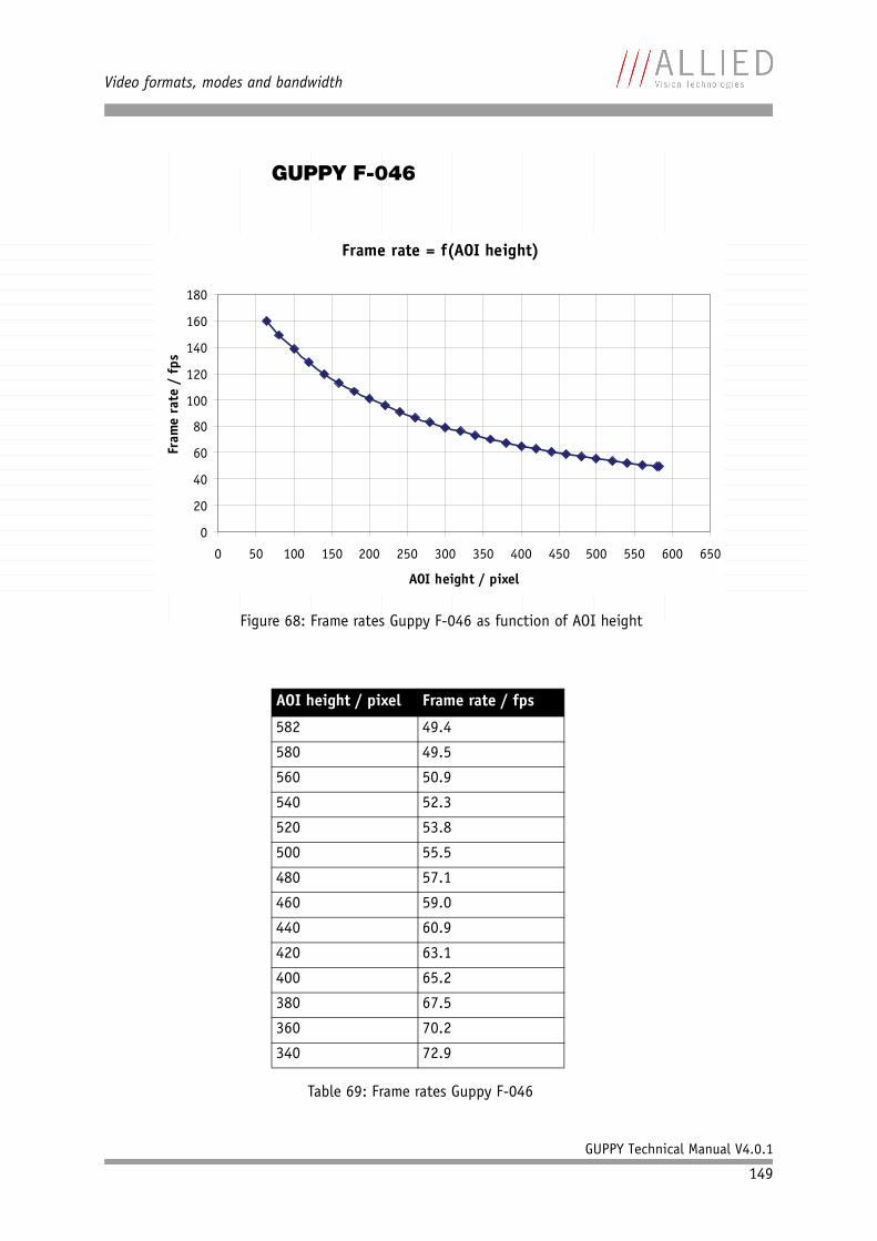
Video formats, modes and bandwidth
GUPPY Technical Manual V4.0.1
149
GUPPY F-046
Figure 68: Frame rates Guppy F-046 as function of AOI height
AOI height / pixel Frame rate / fps
582 49.4
580 49.5
560 50.9
540 52.3
520 53.8
500 55.5
480 57.1
460 59.0
440 60.9
420 63.1
400 65.2
380 67.5
360 70.2
340 72.9
Table 69: Frame rates Guppy F-046
Frame rate = f(AOI height)
0
20
40
60
80
100
120
140
160
180
0 50 100 150 200 250 300 350 400 450 500 550 600 650
AOI height / pixel
Fram
e ra
te /
fps
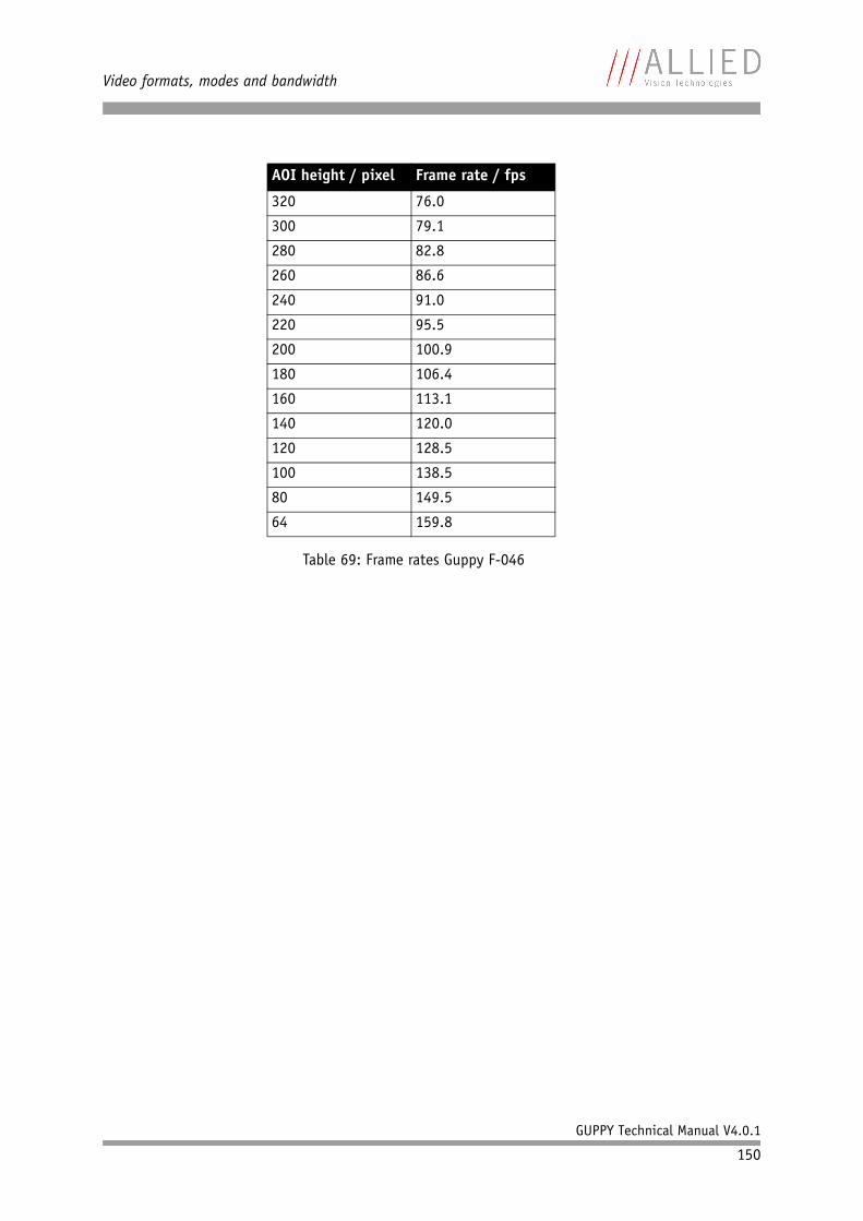
Video formats, modes and bandwidth
GUPPY Technical Manual V4.0.1
150
320 76.0
300 79.1
280 82.8
260 86.6
240 91.0
220 95.5
200 100.9
180 106.4
160 113.1
140 120.0
120 128.5
100 138.5
80 149.5
64 159.8
AOI height / pixel Frame rate / fps
Table 69: Frame rates Guppy F-046
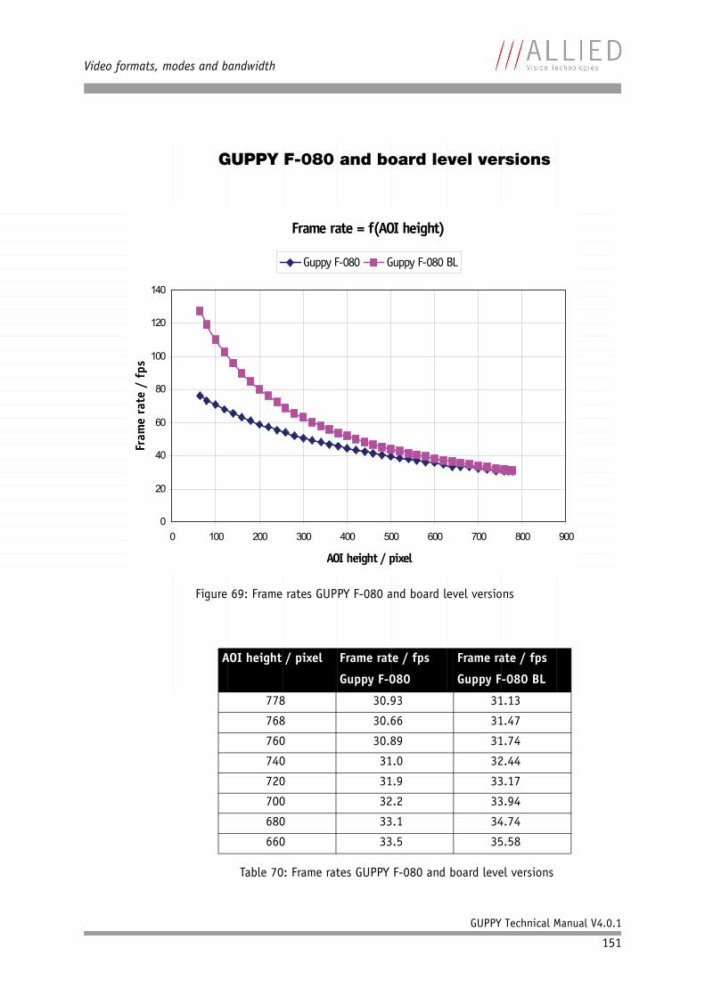
Video formats, modes and bandwidth
GUPPY Technical Manual V4.0.1
151
GUPPY F-080 and board level versions
Figure 69: Frame rates GUPPY F-080 and board level versions
AOI height / pixel Frame rate / fps
Guppy F-080
Frame rate / fps
Guppy F-080 BL
778 30.93 31.13
768 30.66 31.47
760 30.89 31.74
740 31.0 32.44
720 31.9 33.17
700 32.2 33.94
680 33.1 34.74
660 33.5 35.58
Table 70: Frame rates GUPPY F-080 and board level versions
Frame rate = f(AOI height)
0
20
40
60
80
100
120
140
0 100 200 300 400 500 600 700 800 900
AOI height / pixel
Fram
e ra
te /
fps
Guppy F-080 Guppy F-080 BL
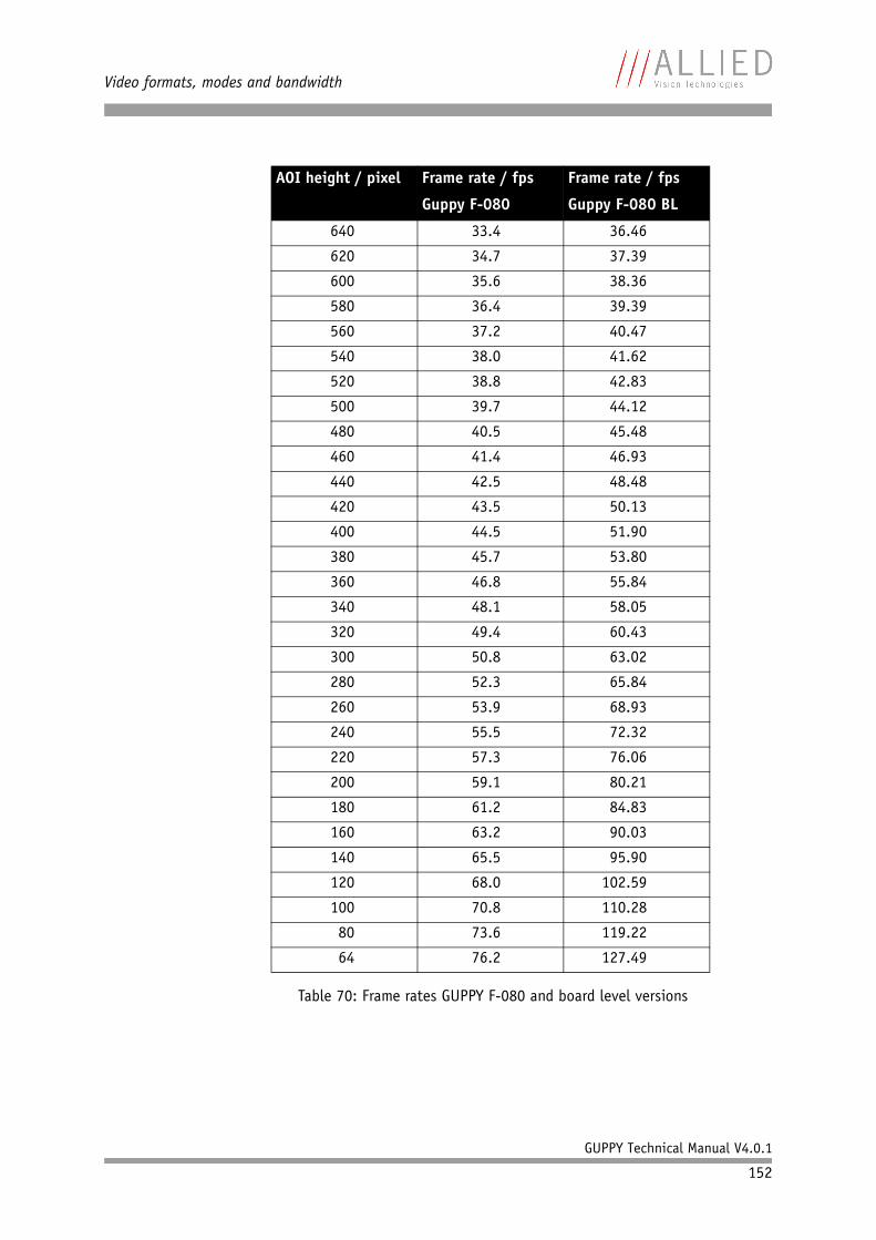
Video formats, modes and bandwidth
GUPPY Technical Manual V4.0.1
152
640 33.4 36.46
620 34.7 37.39
600 35.6 38.36
580 36.4 39.39
560 37.2 40.47
540 38.0 41.62
520 38.8 42.83
500 39.7 44.12
480 40.5 45.48
460 41.4 46.93
440 42.5 48.48
420 43.5 50.13
400 44.5 51.90
380 45.7 53.80
360 46.8 55.84
340 48.1 58.05
320 49.4 60.43
300 50.8 63.02
280 52.3 65.84
260 53.9 68.93
240 55.5 72.32
220 57.3 76.06
200 59.1 80.21
180 61.2 84.83
160 63.2 90.03
140 65.5 95.90
120 68.0 102.59
100 70.8 110.28
80 73.6 119.22
64 76.2 127.49
AOI height / pixel Frame rate / fps
Guppy F-080
Frame rate / fps
Guppy F-080 BL
Table 70: Frame rates GUPPY F-080 and board level versions
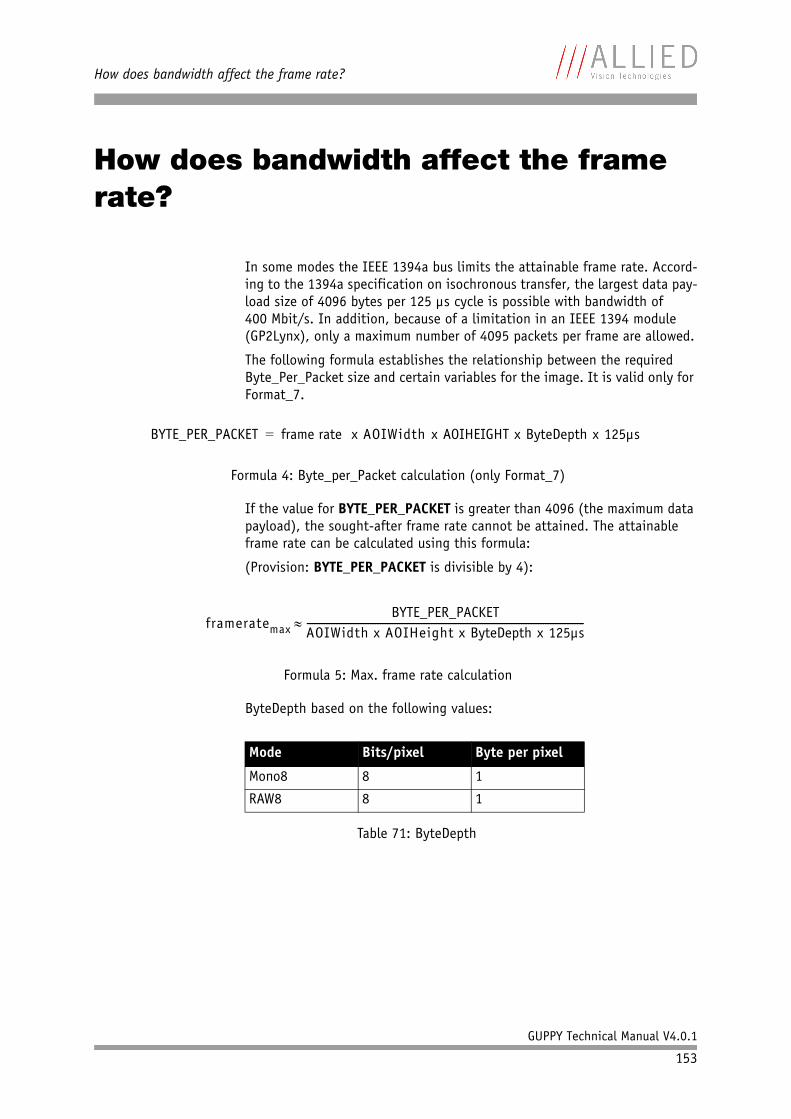
How does bandwidth affect the frame rate?
GUPPY Technical Manual V4.0.1
153
How does bandwidth affect the frame rate?
In some modes the IEEE 1394a bus limits the attainable frame rate. Accord-ing to the 1394a specification on isochronous transfer, the largest data pay-load size of 4096 bytes per 125 µs cycle is possible with bandwidth of 400 Mbit/s. In addition, because of a limitation in an IEEE 1394 module (GP2Lynx), only a maximum number of 4095 packets per frame are allowed.
The following formula establishes the relationship between the required Byte_Per_Packet size and certain variables for the image. It is valid only for Format_7.
If the value for BYTE_PER_PACKET is greater than 4096 (the maximum data payload), the sought-after frame rate cannot be attained. The attainable frame rate can be calculated using this formula:
(Provision: BYTE_PER_PACKET is divisible by 4):
ByteDepth based on the following values:
Formula 4: Byte_per_Packet calculation (only Format_7)
Formula 5: Max. frame rate calculation
Mode Bits/pixel Byte per pixel
Mono8 8 1
RAW8 8 1
Table 71: ByteDepth
BYTE_PER_PACKET frame rate x AOIWidth x AOIHEIGHT x ByteDepth x 125µs=
frameratemaxBYTE_PER_PACKET
AOIWidth x AOIHeight x ByteDepth x 125µs------------------------------------------------------------------------------------------------------------------≈
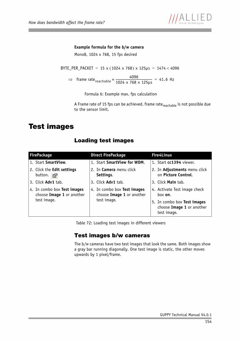
How does bandwidth affect the frame rate?
GUPPY Technical Manual V4.0.1
154
Example formula for the b/w camera
Mono8, 1024 x 768, 15 fps desired
A Frame rate of 15 fps can be achieved. frame ratereachable is not possible due to the sensor limit.
Test images
Loading test images
Test images b/w camerasThe b/w cameras have two test images that look the same. Both images show a gray bar running diagonally. One test image is static, the other moves upwards by 1 pixel/frame.
Formula 6: Example max. fps calculation
FirePackage Direct FirePackage Fire4Linux
1. Start SmartView.
2. Click the Edit settings button.
3. Click Adv1 tab.
4. In combo box Test images choose Image 1 or another test image.
1. Start SmartView for WDM.
2. In Camera menu click Settings.
3. Click Adv1 tab.
4. In combo box Test images choose Image 1 or another test image.
1. Start cc1394 viewer.
2. In Adjustments menu click on Picture Control.
3. Click Main tab.
4. Activate Test image check box on.
5. In combo box Test images choose Image 1 or another test image.
Table 72: Loading test images in different viewers
BYTE_PER_PACKET 15 x 1024 x 768( ) x 125µs 1474 4096<= =
frame ratereachable4096
1024 x 768 x 125µs-------------------------------------------------≈⇒ 41.6 Hz=

How does bandwidth affect the frame rate?
GUPPY Technical Manual V4.0.1
155
Figure 70: Gray bar test image
Formula 7: Calculating the gray value
Gray value x y+( )MOD256= 8-bit mode( )
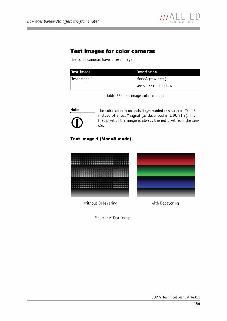
How does bandwidth affect the frame rate?
GUPPY Technical Manual V4.0.1
156
Test images for color camerasThe color cameras have 1 test image.
Test image 1 (Mono8 mode)
Test image Description
Test image 1 Mono8 (raw data)
see screenshot below
Table 73: Test image color cameras
Note The color camera outputs Bayer-coded raw data in Mono8 instead of a real Y signal (as described in IIDC V1.3). The first pixel of the image is always the red pixel from the sen-sor.
Figure 71: Test image 1
without Debayering with Debayering
Configuration of the camera
GUPPY Technical Manual V4.0.1
157
Configuration of the camera
All camera settings are made by writing specific values into the correspond-ing registers.
This applies to:• values for general operating states such as video formats and modes,
exposure times, etc.• extended features of the camera that are turned on and off and con-
trolled via corresponding registers (so-called advanced registers).
Camera_Status_Register
The interoperability of cameras from different manufacturers is ensured by IIDC, formerly DCAM (Digital Camera Specification), published by the IEEE 1394 Trade Association.
IIDC is primarily concerned with setting memory addresses (e.g. CSR: Camera_Status_Register) and their meaning.
In principle all addresses in IEEE 1394 networks are 64 bits long.
The first 10 bits describe the Bus_Id, the next 6 bits the Node_Id.
Of the subsequent 48 bits, the first 16 are is always FFFFh, leaving the description for the Camera_Status_Register in the last 32 bits.
If a CSR F0F00600h is mentioned below this means in full:
Bus_Id, Node_Id, FFFF F0F00600h
Writing and reading to and from the register can be done with programs such as FireView or by other programs developed using an API library (e.g. FirePackage).
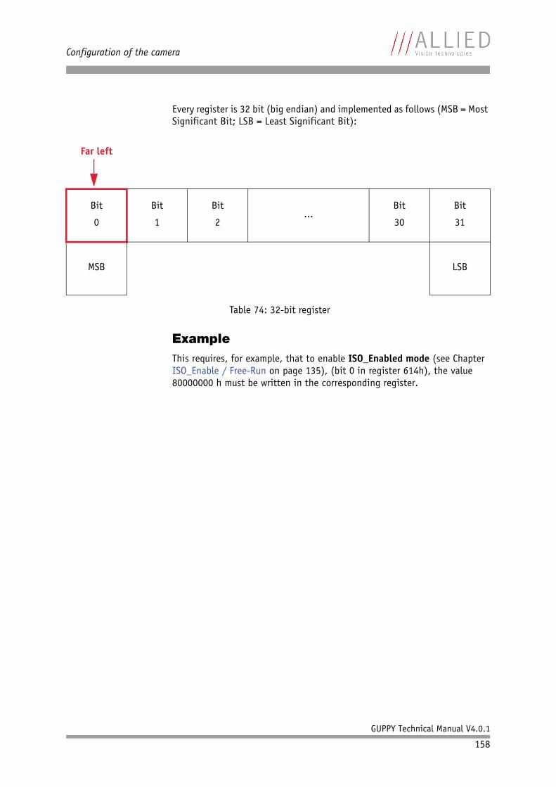
Configuration of the camera
GUPPY Technical Manual V4.0.1
158
Every register is 32 bit (big endian) and implemented as follows (MSB = Most Significant Bit; LSB = Least Significant Bit):
ExampleThis requires, for example, that to enable ISO_Enabled mode (see Chapter ISO_Enable / Free-Run on page 135), (bit 0 in register 614h), the value 80000000 h must be written in the corresponding register.
Far left
Bit
0
Bit
1
Bit
2...
Bit
30
Bit
31
MSB LSB
Table 74: 32-bit register
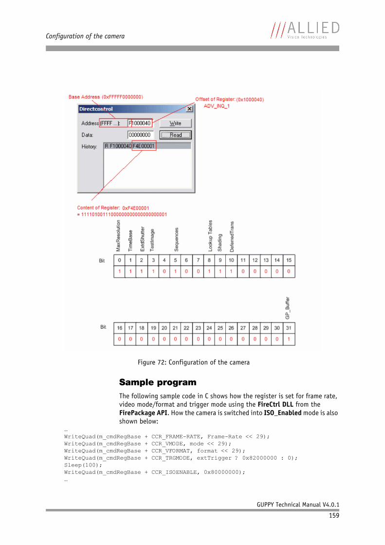
Configuration of the camera
GUPPY Technical Manual V4.0.1
159
Sample programThe following sample code in C shows how the register is set for frame rate, video mode/format and trigger mode using the FireCtrl DLL from the FirePackage API. How the camera is switched into ISO_Enabled mode is also shown below:
…WriteQuad(m_cmdRegBase + CCR_FRAME-RATE, Frame-Rate << 29);WriteQuad(m_cmdRegBase + CCR_VMODE, mode << 29);WriteQuad(m_cmdRegBase + CCR_VFORMAT, format << 29);WriteQuad(m_cmdRegBase + CCR_TRGMODE, extTrigger ? 0x82000000 : 0);Sleep(100);WriteQuad(m_cmdRegBase + CCR_ISOENABLE, 0x80000000);…
Figure 72: Configuration of the camera
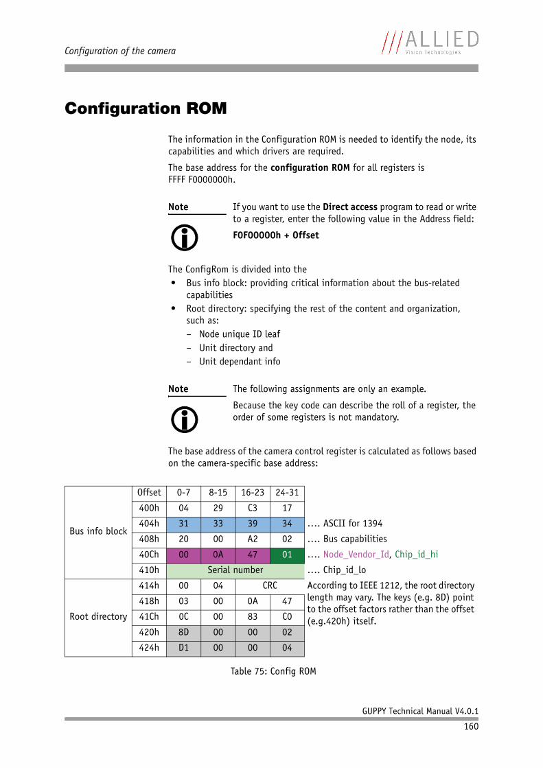
Configuration of the camera
GUPPY Technical Manual V4.0.1
160
Configuration ROM
The information in the Configuration ROM is needed to identify the node, its capabilities and which drivers are required.
The base address for the configuration ROM for all registers is FFFF F0000000h.
The ConfigRom is divided into the• Bus info block: providing critical information about the bus-related
capabilities• Root directory: specifying the rest of the content and organization,
such as:– Node unique ID leaf– Unit directory and– Unit dependant info
The base address of the camera control register is calculated as follows based on the camera-specific base address:
Note If you want to use the Direct access program to read or write to a register, enter the following value in the Address field:
F0F00000h + Offset
Note The following assignments are only an example.
Because the key code can describe the roll of a register, the order of some registers is not mandatory.
Bus info block
Offset 0-7 8-15 16-23 24-31
400h 04 29 C3 17
404h 31 33 39 34 …. ASCII for 1394
408h 20 00 A2 02 …. Bus capabilities
40Ch 00 0A 47 01 …. Node_Vendor_Id, Chip_id_hi
410h Serial number …. Chip_id_lo
Root directory
414h 00 04 CRC According to IEEE 1212, the root directory length may vary. The keys (e.g. 8D) point to the offset factors rather than the offset (e.g.420h) itself.
418h 03 00 0A 47
41Ch 0C 00 83 C0
420h 8D 00 00 02
424h D1 00 00 04
Table 75: Config ROM
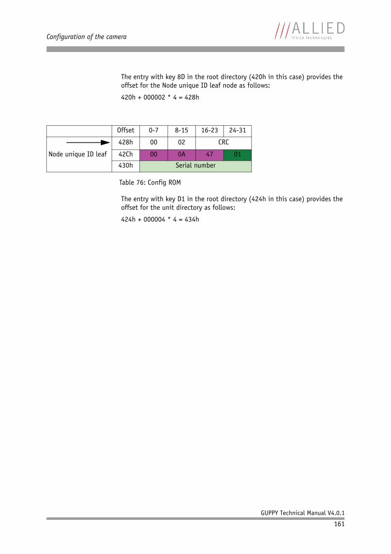
Configuration of the camera
GUPPY Technical Manual V4.0.1
161
The entry with key 8D in the root directory (420h in this case) provides the offset for the Node unique ID leaf node as follows:
420h + 000002 * 4 = 428h
The entry with key D1 in the root directory (424h in this case) provides the offset for the unit directory as follows:
424h + 000004 * 4 = 434h
Offset 0-7 8-15 16-23 24-31
428h 00 02 CRC
Node unique ID leaf 42Ch 00 0A 47 01
430h Serial number
Table 76: Config ROM
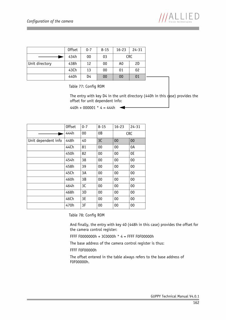
Configuration of the camera
GUPPY Technical Manual V4.0.1
162
The entry with key D4 in the unit directory (440h in this case) provides the offset for unit dependent info:
440h + 000001 * 4 = 444h
And finally, the entry with key 40 (448h in this case) provides the offset for the camera control register:
FFFF F0000000h + 3C0000h * 4 = FFFF F0F00000h
The base address of the camera control register is thus:
FFFF F0F00000h
The offset entered in the table always refers to the base address of F0F00000h.
Offset 0-7 8-15 16-23 24-31
434h 00 03 CRC
Unit directory 438h 12 00 A0 2D
43Ch 13 00 01 02
440h D4 00 00 01
Table 77: Config ROM
Offset 0-7 8-15 16-23 24-31
444h 00 0B CRC
Unit dependent info 448h 40 3C 00 00
44Ch 81 00 00 0A
450h 82 00 00 0E
454h 38 00 00 00
458h 39 00 00 00
45Ch 3A 00 00 00
460h 3B 00 00 00
464h 3C 00 00 00
468h 3D 00 00 00
46Ch 3E 00 00 00
470h 3F 00 00 00
Table 78: Config ROM
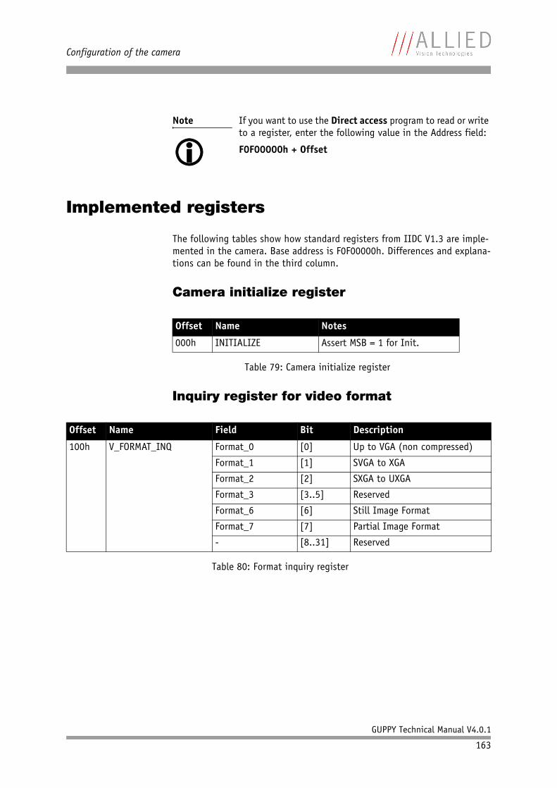
Configuration of the camera
GUPPY Technical Manual V4.0.1
163
Implemented registers
The following tables show how standard registers from IIDC V1.3 are imple-mented in the camera. Base address is F0F00000h. Differences and explana-tions can be found in the third column.
Camera initialize register
Inquiry register for video format
Note If you want to use the Direct access program to read or write to a register, enter the following value in the Address field:
F0F00000h + Offset
Offset Name Notes
000h INITIALIZE Assert MSB = 1 for Init.
Table 79: Camera initialize register
Offset Name Field Bit Description
100h V_FORMAT_INQ Format_0 [0] Up to VGA (non compressed)
Format_1 [1] SVGA to XGA
Format_2 [2] SXGA to UXGA
Format_3 [3..5] Reserved
Format_6 [6] Still Image Format
Format_7 [7] Partial Image Format
- [8..31] Reserved
Table 80: Format inquiry register
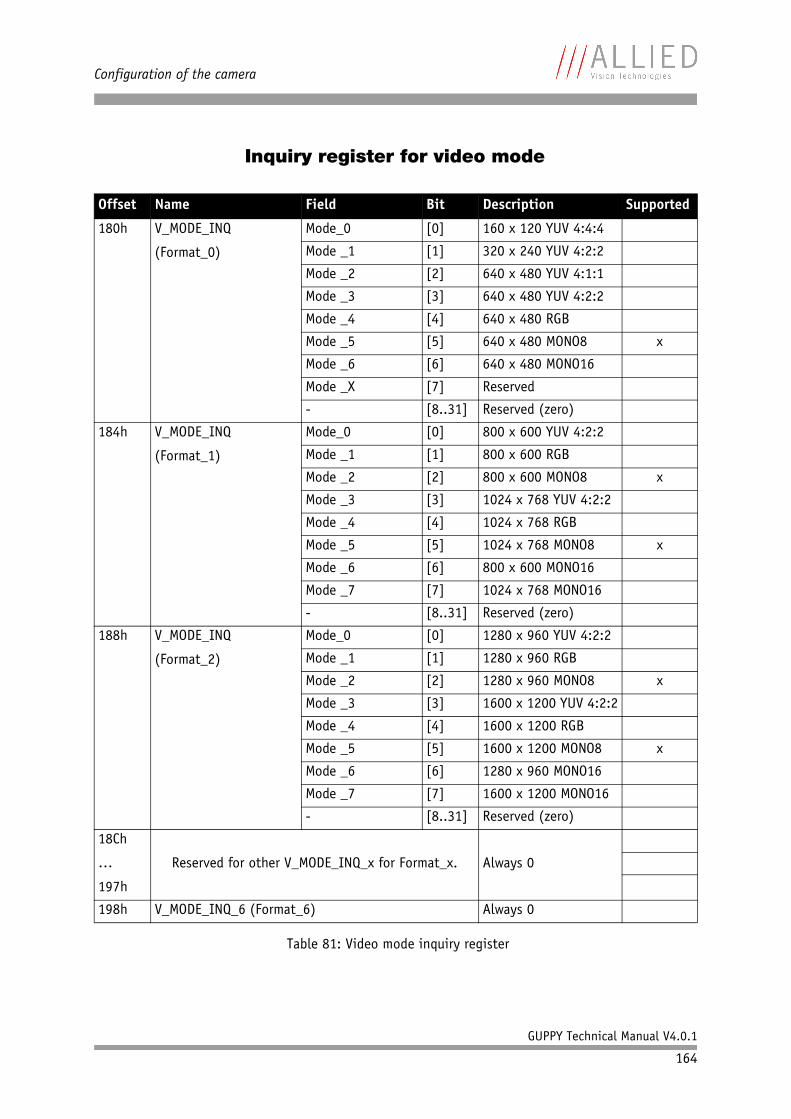
Configuration of the camera
GUPPY Technical Manual V4.0.1
164
Inquiry register for video mode
Offset Name Field Bit Description Supported
180h V_MODE_INQ
(Format_0)
Mode_0 [0] 160 x 120 YUV 4:4:4
Mode _1 [1] 320 x 240 YUV 4:2:2
Mode _2 [2] 640 x 480 YUV 4:1:1
Mode _3 [3] 640 x 480 YUV 4:2:2
Mode _4 [4] 640 x 480 RGB
Mode _5 [5] 640 x 480 MONO8 x
Mode _6 [6] 640 x 480 MONO16
Mode _X [7] Reserved
- [8..31] Reserved (zero)
184h V_MODE_INQ
(Format_1)
Mode_0 [0] 800 x 600 YUV 4:2:2
Mode _1 [1] 800 x 600 RGB
Mode _2 [2] 800 x 600 MONO8 x
Mode _3 [3] 1024 x 768 YUV 4:2:2
Mode _4 [4] 1024 x 768 RGB
Mode _5 [5] 1024 x 768 MONO8 x
Mode _6 [6] 800 x 600 MONO16
Mode _7 [7] 1024 x 768 MONO16
- [8..31] Reserved (zero)
188h V_MODE_INQ
(Format_2)
Mode_0 [0] 1280 x 960 YUV 4:2:2
Mode _1 [1] 1280 x 960 RGB
Mode _2 [2] 1280 x 960 MONO8 x
Mode _3 [3] 1600 x 1200 YUV 4:2:2
Mode _4 [4] 1600 x 1200 RGB
Mode _5 [5] 1600 x 1200 MONO8 x
Mode _6 [6] 1280 x 960 MONO16
Mode _7 [7] 1600 x 1200 MONO16
- [8..31] Reserved (zero)
18Ch
…
197h
Reserved for other V_MODE_INQ_x for Format_x. Always 0
198h V_MODE_INQ_6 (Format_6) Always 0
Table 81: Video mode inquiry register
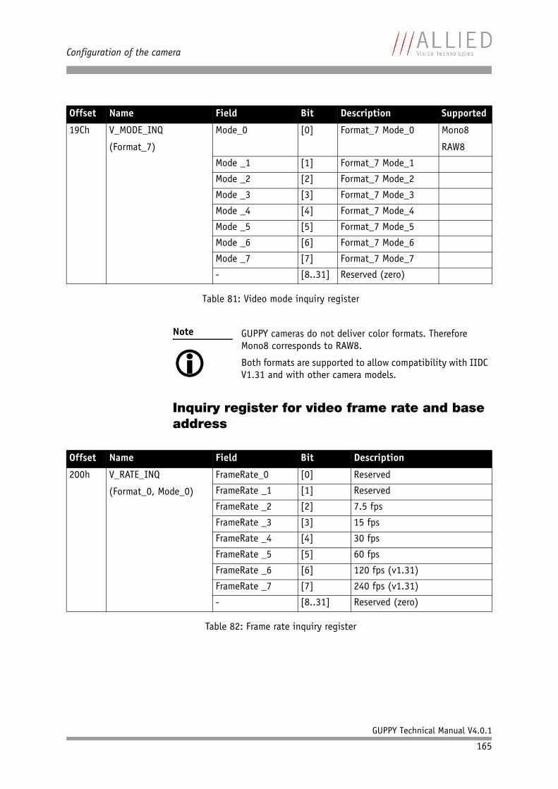
Configuration of the camera
GUPPY Technical Manual V4.0.1
165
Inquiry register for video frame rate and base address
19Ch V_MODE_INQ
(Format_7)
Mode_0 [0] Format_7 Mode_0 Mono8
RAW8
Mode _1 [1] Format_7 Mode_1
Mode _2 [2] Format_7 Mode_2
Mode _3 [3] Format_7 Mode_3
Mode _4 [4] Format_7 Mode_4
Mode _5 [5] Format_7 Mode_5
Mode _6 [6] Format_7 Mode_6
Mode _7 [7] Format_7 Mode_7
- [8..31] Reserved (zero)
Note GUPPY cameras do not deliver color formats. Therefore Mono8 corresponds to RAW8.
Both formats are supported to allow compatibility with IIDC V1.31 and with other camera models.
Offset Name Field Bit Description
200h V_RATE_INQ
(Format_0, Mode_0)
FrameRate_0 [0] Reserved
FrameRate _1 [1] Reserved
FrameRate _2 [2] 7.5 fps
FrameRate _3 [3] 15 fps
FrameRate _4 [4] 30 fps
FrameRate _5 [5] 60 fps
FrameRate _6 [6] 120 fps (v1.31)
FrameRate _7 [7] 240 fps (v1.31)
- [8..31] Reserved (zero)
Table 82: Frame rate inquiry register
Offset Name Field Bit Description Supported
Table 81: Video mode inquiry register
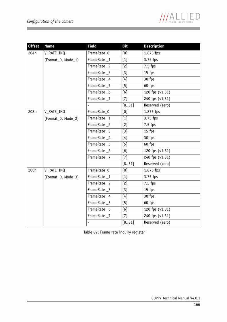
Configuration of the camera
GUPPY Technical Manual V4.0.1
166
204h V_RATE_INQ
(Format_0, Mode_1)
FrameRate_0 [0] 1.875 fps
FrameRate _1 [1] 3.75 fps
FrameRate _2 [2] 7.5 fps
FrameRate _3 [3] 15 fps
FrameRate _4 [4] 30 fps
FrameRate _5 [5] 60 fps
FrameRate _6 [6] 120 fps (v1.31)
FrameRate _7 [7] 240 fps (v1.31)
- [8..31] Reserved (zero)
208h V_RATE_INQ
(Format_0, Mode_2)
FrameRate_0 [0] 1.875 fps
FrameRate _1 [1] 3.75 fps
FrameRate _2 [2] 7.5 fps
FrameRate _3 [3] 15 fps
FrameRate _4 [4] 30 fps
FrameRate _5 [5] 60 fps
FrameRate _6 [6] 120 fps (v1.31)
FrameRate _7 [7] 240 fps (v1.31)
- [8..31] Reserved (zero)
20Ch V_RATE_INQ
(Format_0, Mode_3)
FrameRate_0 [0] 1.875 fps
FrameRate _1 [1] 3.75 fps
FrameRate _2 [2] 7.5 fps
FrameRate _3 [3] 15 fps
FrameRate _4 [4] 30 fps
FrameRate _5 [5] 60 fps
FrameRate _6 [6] 120 fps (v1.31)
FrameRate _7 [7] 240 fps (v1.31)
- [8..31] Reserved (zero)
Offset Name Field Bit Description
Table 82: Frame rate inquiry register
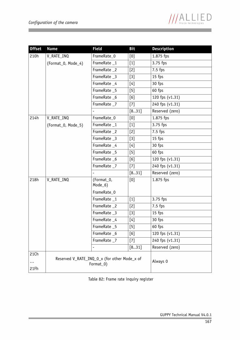
Configuration of the camera
GUPPY Technical Manual V4.0.1
167
210h V_RATE_INQ
(Format_0, Mode_4)
FrameRate_0 [0] 1.875 fps
FrameRate _1 [1] 3.75 fps
FrameRate _2 [2] 7.5 fps
FrameRate _3 [3] 15 fps
FrameRate _4 [4] 30 fps
FrameRate _5 [5] 60 fps
FrameRate _6 [6] 120 fps (v1.31)
FrameRate _7 [7] 240 fps (v1.31)
- [8..31] Reserved (zero)
214h V_RATE_INQ
(Format_0, Mode_5)
FrameRate_0 [0] 1.875 fps
FrameRate _1 [1] 3.75 fps
FrameRate _2 [2] 7.5 fps
FrameRate _3 [3] 15 fps
FrameRate _4 [4] 30 fps
FrameRate _5 [5] 60 fps
FrameRate _6 [6] 120 fps (v1.31)
FrameRate _7 [7] 240 fps (v1.31)
- [8..31] Reserved (zero)
218h V_RATE_INQ (Format_0, Mode_6)
FrameRate_0
[0] 1.875 fps
FrameRate _1 [1] 3.75 fps
FrameRate _2 [2] 7.5 fps
FrameRate _3 [3] 15 fps
FrameRate _4 [4] 30 fps
FrameRate _5 [5] 60 fps
FrameRate _6 [6] 120 fps (v1.31)
FrameRate _7 [7] 240 fps (v1.31)
- [8..31] Reserved (zero)
21Ch
…
21Fh
Reserved V_RATE_INQ_0_x (for other Mode_x of Format_0)
Always 0
Offset Name Field Bit Description
Table 82: Frame rate inquiry register

Configuration of the camera
GUPPY Technical Manual V4.0.1
168
220h V_RATE_INQ
(Format_1, Mode_0)
FrameRate_0 [0] Reserved
FrameRate _1 [1] 3.75 fps
FrameRate _2 [2] 7.5 fps
FrameRate _3 [3] 15 fps
FrameRate _4 [4] 30 fps
FrameRate _5 [5] 60 fps
FrameRate _6 [6] 120 fps (v1.31)
FrameRate _7 [7] 240 fps (v1.31)
- [8..31] Reserved (zero)
224h V_RATE_INQ
(Format_1, Mode_1)
FrameRate_0 [0] Reserved
FrameRate _1 [1] Reserved
FrameRate _2 [2] 7.5 fps
FrameRate _3 [3] 15 fps
FrameRate _4 [4] 30 fps
FrameRate _5 [5] 60 fps
FrameRate _6 [6] 120 fps (v1.31)
FrameRate _7 [7] 240 fps (v1.31)
- [8..31] Reserved (zero)
228h V_RATE_INQ
(Format_1, Mode_2)
FrameRate_0 [0] Reserved
FrameRate _1 [1] Reserved
FrameRate _2 [2] 7.5 fps
FrameRate _3 [3] 15 fps
FrameRate _4 [4] 30 fps
FrameRate _5 [5] 60 fps
FrameRate _6 [6] 120 fps (v1.31)
FrameRate _7 [7] 240 fps (v1.31)
- [8..31] Reserved (zero)
Offset Name Field Bit Description
Table 82: Frame rate inquiry register
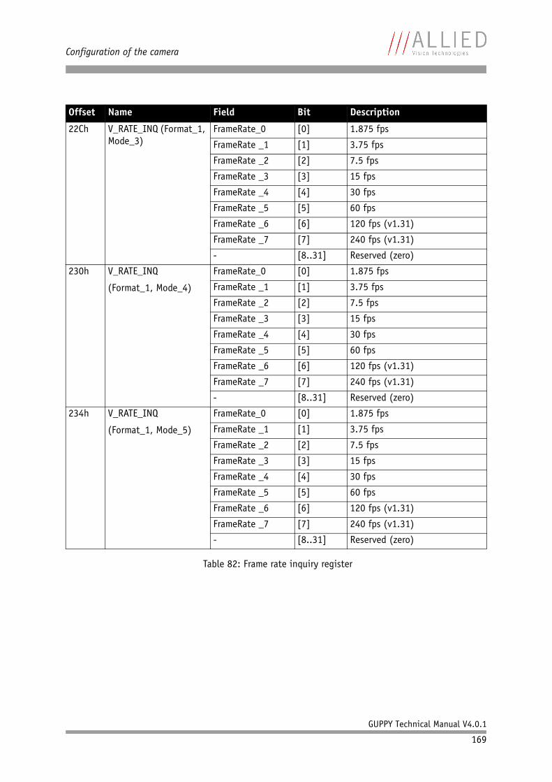
Configuration of the camera
GUPPY Technical Manual V4.0.1
169
22Ch V_RATE_INQ (Format_1, Mode_3)
FrameRate_0 [0] 1.875 fps
FrameRate _1 [1] 3.75 fps
FrameRate _2 [2] 7.5 fps
FrameRate _3 [3] 15 fps
FrameRate _4 [4] 30 fps
FrameRate _5 [5] 60 fps
FrameRate _6 [6] 120 fps (v1.31)
FrameRate _7 [7] 240 fps (v1.31)
- [8..31] Reserved (zero)
230h V_RATE_INQ
(Format_1, Mode_4)
FrameRate_0 [0] 1.875 fps
FrameRate _1 [1] 3.75 fps
FrameRate _2 [2] 7.5 fps
FrameRate _3 [3] 15 fps
FrameRate _4 [4] 30 fps
FrameRate _5 [5] 60 fps
FrameRate _6 [6] 120 fps (v1.31)
FrameRate _7 [7] 240 fps (v1.31)
- [8..31] Reserved (zero)
234h V_RATE_INQ
(Format_1, Mode_5)
FrameRate_0 [0] 1.875 fps
FrameRate _1 [1] 3.75 fps
FrameRate _2 [2] 7.5 fps
FrameRate _3 [3] 15 fps
FrameRate _4 [4] 30 fps
FrameRate _5 [5] 60 fps
FrameRate _6 [6] 120 fps (v1.31)
FrameRate _7 [7] 240 fps (v1.31)
- [8..31] Reserved (zero)
Offset Name Field Bit Description
Table 82: Frame rate inquiry register
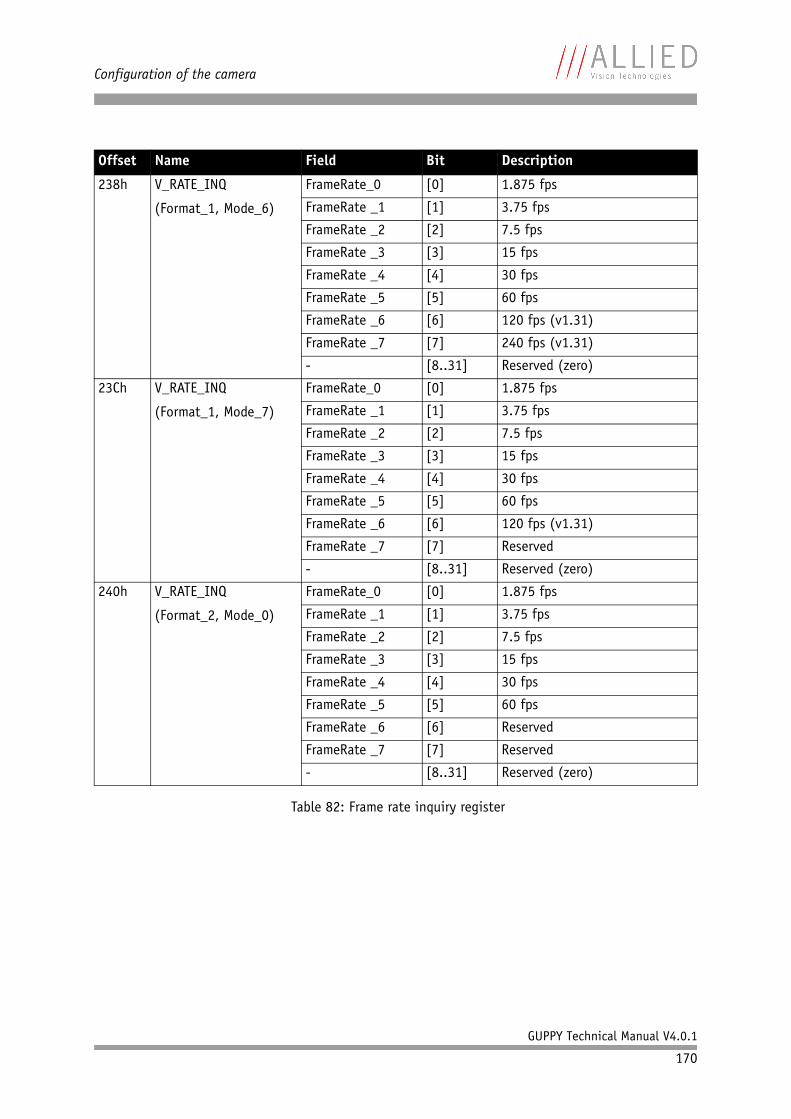
Configuration of the camera
GUPPY Technical Manual V4.0.1
170
238h V_RATE_INQ
(Format_1, Mode_6)
FrameRate_0 [0] 1.875 fps
FrameRate _1 [1] 3.75 fps
FrameRate _2 [2] 7.5 fps
FrameRate _3 [3] 15 fps
FrameRate _4 [4] 30 fps
FrameRate _5 [5] 60 fps
FrameRate _6 [6] 120 fps (v1.31)
FrameRate _7 [7] 240 fps (v1.31)
- [8..31] Reserved (zero)
23Ch V_RATE_INQ
(Format_1, Mode_7)
FrameRate_0 [0] 1.875 fps
FrameRate _1 [1] 3.75 fps
FrameRate _2 [2] 7.5 fps
FrameRate _3 [3] 15 fps
FrameRate _4 [4] 30 fps
FrameRate _5 [5] 60 fps
FrameRate _6 [6] 120 fps (v1.31)
FrameRate _7 [7] Reserved
- [8..31] Reserved (zero)
240h V_RATE_INQ
(Format_2, Mode_0)
FrameRate_0 [0] 1.875 fps
FrameRate _1 [1] 3.75 fps
FrameRate _2 [2] 7.5 fps
FrameRate _3 [3] 15 fps
FrameRate _4 [4] 30 fps
FrameRate _5 [5] 60 fps
FrameRate _6 [6] Reserved
FrameRate _7 [7] Reserved
- [8..31] Reserved (zero)
Offset Name Field Bit Description
Table 82: Frame rate inquiry register
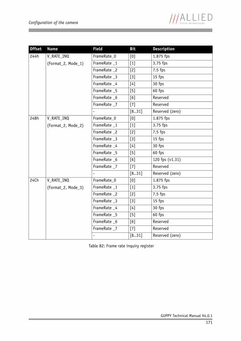
Configuration of the camera
GUPPY Technical Manual V4.0.1
171
244h V_RATE_INQ
(Format_2, Mode_1)
FrameRate_0 [0] 1.875 fps
FrameRate _1 [1] 3.75 fps
FrameRate _2 [2] 7.5 fps
FrameRate _3 [3] 15 fps
FrameRate _4 [4] 30 fps
FrameRate _5 [5] 60 fps
FrameRate _6 [6] Reserved
FrameRate _7 [7] Reserved
- [8..31] Reserved (zero)
248h V_RATE_INQ
(Format_2, Mode_2)
FrameRate_0 [0] 1.875 fps
FrameRate _1 [1] 3.75 fps
FrameRate _2 [2] 7.5 fps
FrameRate _3 [3] 15 fps
FrameRate _4 [4] 30 fps
FrameRate _5 [5] 60 fps
FrameRate _6 [6] 120 fps (v1.31)
FrameRate _7 [7] Reserved
- [8..31] Reserved (zero)
24Ch V_RATE_INQ
(Format_2, Mode_3)
FrameRate_0 [0] 1.875 fps
FrameRate _1 [1] 3.75 fps
FrameRate _2 [2] 7.5 fps
FrameRate _3 [3] 15 fps
FrameRate _4 [4] 30 fps
FrameRate _5 [5] 60 fps
FrameRate _6 [6] Reserved
FrameRate _7 [7] Reserved
- [8..31] Reserved (zero)
Offset Name Field Bit Description
Table 82: Frame rate inquiry register
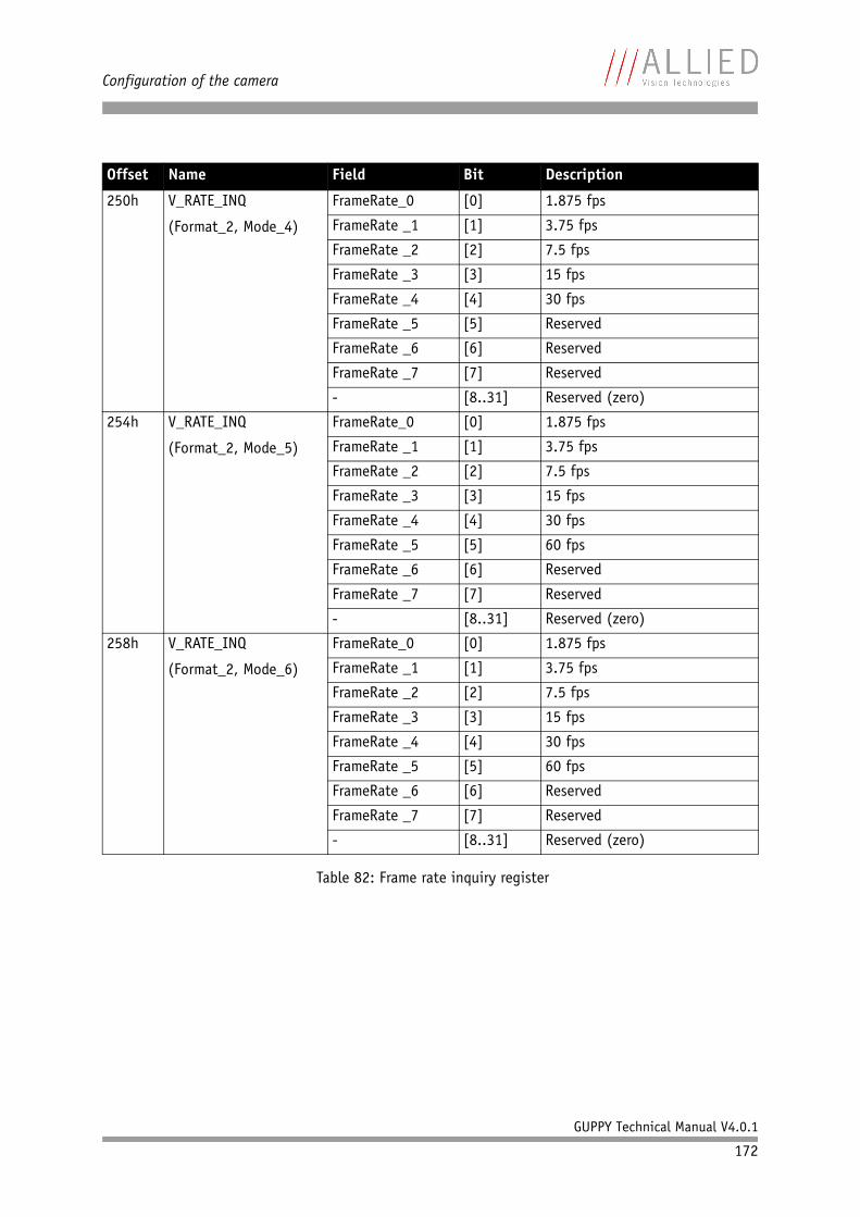
Configuration of the camera
GUPPY Technical Manual V4.0.1
172
250h V_RATE_INQ
(Format_2, Mode_4)
FrameRate_0 [0] 1.875 fps
FrameRate _1 [1] 3.75 fps
FrameRate _2 [2] 7.5 fps
FrameRate _3 [3] 15 fps
FrameRate _4 [4] 30 fps
FrameRate _5 [5] Reserved
FrameRate _6 [6] Reserved
FrameRate _7 [7] Reserved
- [8..31] Reserved (zero)
254h V_RATE_INQ
(Format_2, Mode_5)
FrameRate_0 [0] 1.875 fps
FrameRate _1 [1] 3.75 fps
FrameRate _2 [2] 7.5 fps
FrameRate _3 [3] 15 fps
FrameRate _4 [4] 30 fps
FrameRate _5 [5] 60 fps
FrameRate _6 [6] Reserved
FrameRate _7 [7] Reserved
- [8..31] Reserved (zero)
258h V_RATE_INQ
(Format_2, Mode_6)
FrameRate_0 [0] 1.875 fps
FrameRate _1 [1] 3.75 fps
FrameRate _2 [2] 7.5 fps
FrameRate _3 [3] 15 fps
FrameRate _4 [4] 30 fps
FrameRate _5 [5] 60 fps
FrameRate _6 [6] Reserved
FrameRate _7 [7] Reserved
- [8..31] Reserved (zero)
Offset Name Field Bit Description
Table 82: Frame rate inquiry register
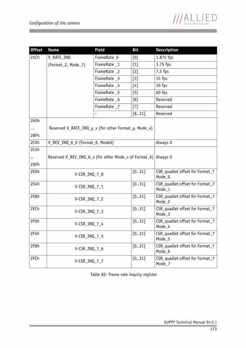
Configuration of the camera
GUPPY Technical Manual V4.0.1
173
25Ch V_RATE_INQ
(Format_2, Mode_7)
FrameRate_0 [0] 1.875 fps
FrameRate _1 [1] 3.75 fps
FrameRate _2 [2] 7.5 fps
FrameRate _3 [3] 15 fps
FrameRate _4 [4] 30 fps
FrameRate _5 [5] 60 fps
FrameRate _6 [6] Reserved
FrameRate _7 [7] Reserved
- [8..31] Reserved
260h
…
2BFh
Reserved V_RATE_INQ_y_x (for other Format_y, Mode_x)
2C0h V_REV_INQ_6_0 (Format_6, Mode0) Always 0
2C4h
..
2DFh
Reserved V_REV_INQ_6_x (for other Mode_x of Format_6) Always 0
2E0hV-CSR_INQ_7_0
[0..31] CSR_quadlet offset for Format_7 Mode_0
2E4hV-CSR_INQ_7_1
[0..31] CSR_quadlet offset for Format_7 Mode_1
2E8hV-CSR_INQ_7_2
[0..31] CSR_quadlet offset for Format_7 Mode_2
2EChV-CSR_INQ_7_3
[0..31] CSR_quadlet offset for Format_7 Mode_3
2F0hV-CSR_INQ_7_4
[0..31] CSR_quadlet offset for Format_7 Mode_4
2F4hV-CSR_INQ_7_5
[0..31] CSR_quadlet offset for Format_7 Mode_5
2F8hV-CSR_INQ_7_6
[0..31] CSR_quadlet offset for Format_7 Mode_6
2FChV-CSR_INQ_7_7
[0..31] CSR_quadlet offset for Format_7 Mode_7
Offset Name Field Bit Description
Table 82: Frame rate inquiry register
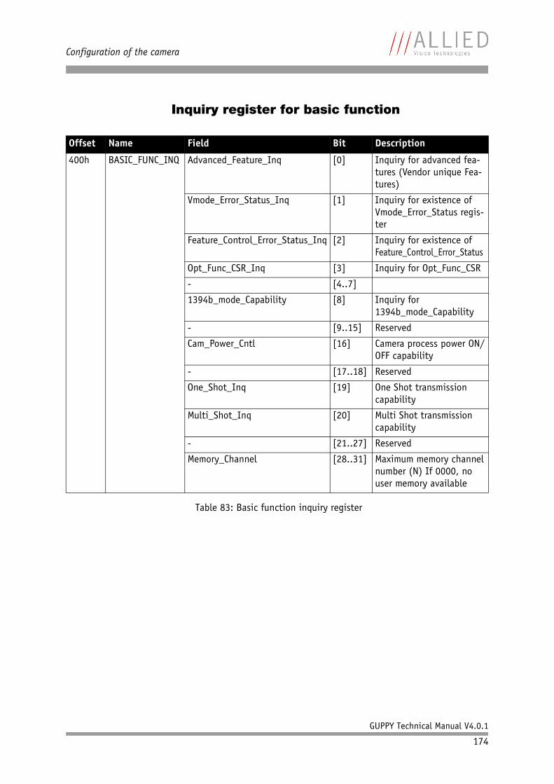
Configuration of the camera
GUPPY Technical Manual V4.0.1
174
Inquiry register for basic function
Offset Name Field Bit Description
400h BASIC_FUNC_INQ Advanced_Feature_Inq [0] Inquiry for advanced fea-tures (Vendor unique Fea-tures)
Vmode_Error_Status_Inq [1] Inquiry for existence of Vmode_Error_Status regis-ter
Feature_Control_Error_Status_Inq [2] Inquiry for existence of Feature_Control_Error_Status
Opt_Func_CSR_Inq [3] Inquiry for Opt_Func_CSR
- [4..7]
1394b_mode_Capability [8] Inquiry for 1394b_mode_Capability
- [9..15] Reserved
Cam_Power_Cntl [16] Camera process power ON/OFF capability
- [17..18] Reserved
One_Shot_Inq [19] One Shot transmission capability
Multi_Shot_Inq [20] Multi Shot transmission capability
- [21..27] Reserved
Memory_Channel [28..31] Maximum memory channel number (N) If 0000, no user memory available
Table 83: Basic function inquiry register
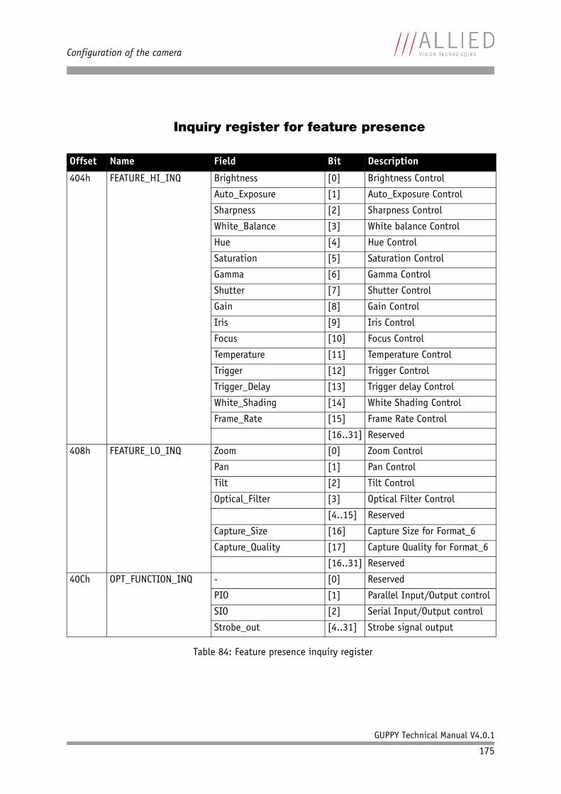
Configuration of the camera
GUPPY Technical Manual V4.0.1
175
Inquiry register for feature presence
Offset Name Field Bit Description
404h FEATURE_HI_INQ Brightness [0] Brightness Control
Auto_Exposure [1] Auto_Exposure Control
Sharpness [2] Sharpness Control
White_Balance [3] White balance Control
Hue [4] Hue Control
Saturation [5] Saturation Control
Gamma [6] Gamma Control
Shutter [7] Shutter Control
Gain [8] Gain Control
Iris [9] Iris Control
Focus [10] Focus Control
Temperature [11] Temperature Control
Trigger [12] Trigger Control
Trigger_Delay [13] Trigger delay Control
White_Shading [14] White Shading Control
Frame_Rate [15] Frame Rate Control
[16..31] Reserved
408h FEATURE_LO_INQ Zoom [0] Zoom Control
Pan [1] Pan Control
Tilt [2] Tilt Control
Optical_Filter [3] Optical Filter Control
[4..15] Reserved
Capture_Size [16] Capture Size for Format_6
Capture_Quality [17] Capture Quality for Format_6
[16..31] Reserved
40Ch OPT_FUNCTION_INQ - [0] Reserved
PIO [1] Parallel Input/Output control
SIO [2] Serial Input/Output control
Strobe_out [4..31] Strobe signal output
Table 84: Feature presence inquiry register
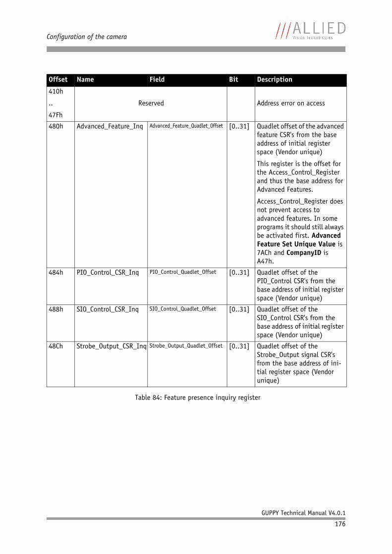
Configuration of the camera
GUPPY Technical Manual V4.0.1
176
410h
..
47Fh
Reserved Address error on access
480h Advanced_Feature_Inq Advanced_Feature_Quadlet_Offset [0..31] Quadlet offset of the advanced feature CSR's from the base address of initial register space (Vendor unique)
This register is the offset for the Access_Control_Register and thus the base address for Advanced Features.
Access_Control_Register does not prevent access to advanced features. In some programs it should still always be activated first. Advanced Feature Set Unique Value is 7ACh and CompanyID is A47h.
484h PIO_Control_CSR_Inq PIO_Control_Quadlet_Offset [0..31] Quadlet offset of the PIO_Control CSR's from the base address of initial register space (Vendor unique)
488h SIO_Control_CSR_Inq SIO_Control_Quadlet_Offset [0..31] Quadlet offset of the SIO_Control CSR's from the base address of initial register space (Vendor unique)
48Ch Strobe_Output_CSR_Inq Strobe_Output_Quadlet_Offset [0..31] Quadlet offset of the Strobe_Output signal CSR's from the base address of ini-tial register space (Vendor unique)
Offset Name Field Bit Description
Table 84: Feature presence inquiry register
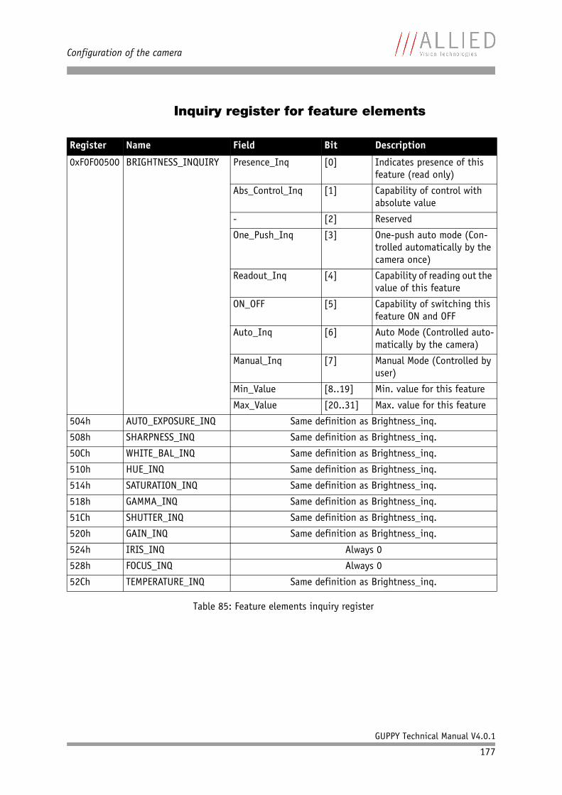
Configuration of the camera
GUPPY Technical Manual V4.0.1
177
Inquiry register for feature elements
Register Name Field Bit Description
0xF0F00500 BRIGHTNESS_INQUIRY Presence_Inq [0] Indicates presence of this feature (read only)
Abs_Control_Inq [1] Capability of control with absolute value
- [2] Reserved
One_Push_Inq [3] One-push auto mode (Con-trolled automatically by the camera once)
Readout_Inq [4] Capability of reading out the value of this feature
ON_OFF [5] Capability of switching this feature ON and OFF
Auto_Inq [6] Auto Mode (Controlled auto-matically by the camera)
Manual_Inq [7] Manual Mode (Controlled by user)
Min_Value [8..19] Min. value for this feature
Max_Value [20..31] Max. value for this feature
504h AUTO_EXPOSURE_INQ Same definition as Brightness_inq.
508h SHARPNESS_INQ Same definition as Brightness_inq.
50Ch WHITE_BAL_INQ Same definition as Brightness_inq.
510h HUE_INQ Same definition as Brightness_inq.
514h SATURATION_INQ Same definition as Brightness_inq.
518h GAMMA_INQ Same definition as Brightness_inq.
51Ch SHUTTER_INQ Same definition as Brightness_inq.
520h GAIN_INQ Same definition as Brightness_inq.
524h IRIS_INQ Always 0
528h FOCUS_INQ Always 0
52Ch TEMPERATURE_INQ Same definition as Brightness_inq.
Table 85: Feature elements inquiry register
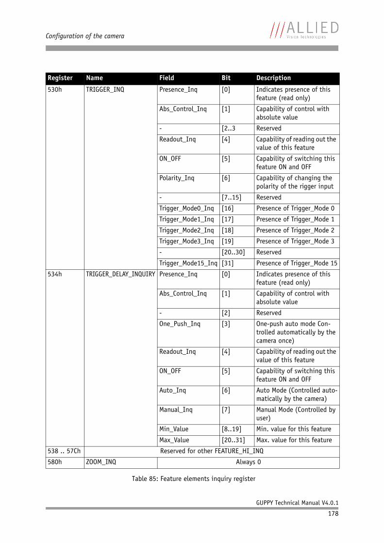
Configuration of the camera
GUPPY Technical Manual V4.0.1
178
530h TRIGGER_INQ Presence_Inq [0] Indicates presence of this feature (read only)
Abs_Control_Inq [1] Capability of control with absolute value
- [2..3 Reserved
Readout_Inq [4] Capability of reading out the value of this feature
ON_OFF [5] Capability of switching this feature ON and OFF
Polarity_Inq [6] Capability of changing the polarity of the rigger input
- [7..15] Reserved
Trigger_Mode0_Inq [16] Presence of Trigger_Mode 0
Trigger_Mode1_Inq [17] Presence of Trigger_Mode 1
Trigger_Mode2_Inq [18] Presence of Trigger_Mode 2
Trigger_Mode3_Inq [19] Presence of Trigger_Mode 3
- [20..30] Reserved
Trigger_Mode15_Inq [31] Presence of Trigger_Mode 15
534h TRIGGER_DELAY_INQUIRY Presence_Inq [0] Indicates presence of this feature (read only)
Abs_Control_Inq [1] Capability of control with absolute value
- [2] Reserved
One_Push_Inq [3] One-push auto mode Con-trolled automatically by the camera once)
Readout_Inq [4] Capability of reading out the value of this feature
ON_OFF [5] Capability of switching this feature ON and OFF
Auto_Inq [6] Auto Mode (Controlled auto-matically by the camera)
Manual_Inq [7] Manual Mode (Controlled by user)
Min_Value [8..19] Min. value for this feature
Max_Value [20..31] Max. value for this feature
538 .. 57Ch Reserved for other FEATURE_HI_INQ
580h ZOOM_INQ Always 0
Register Name Field Bit Description
Table 85: Feature elements inquiry register
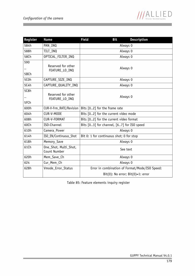
Configuration of the camera
GUPPY Technical Manual V4.0.1
179
584h PAN_INQ Always 0
588h TILT_INQ Always 0
58Ch OPTICAL_FILTER_INQ Always 0
590
..
5BCh
Reserved for other FEATURE_LO_INQ
Always 0
5C0h CAPTURE_SIZE_INQ Always 0
5C4h CAPTURE_QUALITY_INQ Always 0
5C8h
..
5FCh
Reserved for other FEATURE_LO_INQ
Always 0
600h CUR-V-Frm_RATE/Revision Bits [0..2] for the frame rate
604h CUR-V-MODE Bits [0..2] for the current video mode
608h CUR-V-FORMAT Bits [0..2] for the current video format
60Ch ISO-Channel Bits [0..3] for channel, [6..7] for ISO speed
610h Camera_Power Always 0
614h ISO_EN/Continuous_Shot Bit 0: 1 for continuous shot; 0 for stop
618h Memory_Save Always 0
61Ch One_Shot, Multi_Shot, Count Number
See text
620h Mem_Save_Ch Always 0
624 Cur_Mem_Ch Always 0
628h Vmode_Error_Status Error in combination of Format/Mode/ISO Speed:
Bit(0): No error; Bit(0)=1: error
Register Name Field Bit Description
Table 85: Feature elements inquiry register
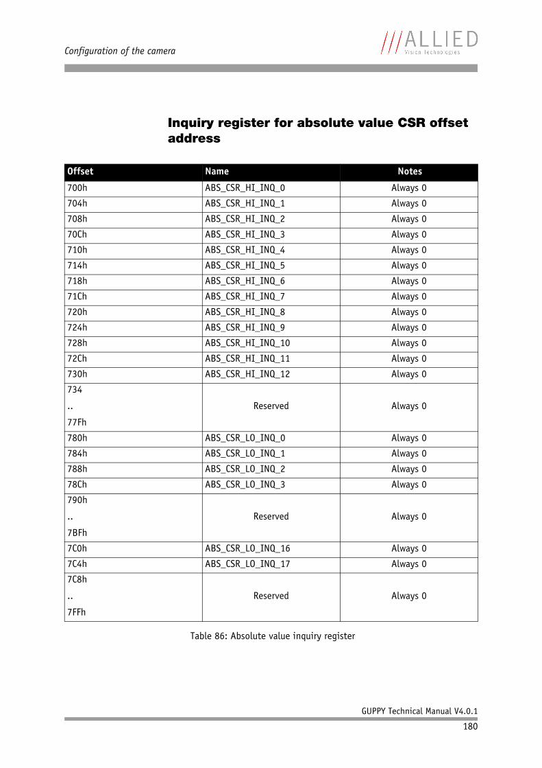
Configuration of the camera
GUPPY Technical Manual V4.0.1
180
Inquiry register for absolute value CSR offset address
Offset Name Notes
700h ABS_CSR_HI_INQ_0 Always 0
704h ABS_CSR_HI_INQ_1 Always 0
708h ABS_CSR_HI_INQ_2 Always 0
70Ch ABS_CSR_HI_INQ_3 Always 0
710h ABS_CSR_HI_INQ_4 Always 0
714h ABS_CSR_HI_INQ_5 Always 0
718h ABS_CSR_HI_INQ_6 Always 0
71Ch ABS_CSR_HI_INQ_7 Always 0
720h ABS_CSR_HI_INQ_8 Always 0
724h ABS_CSR_HI_INQ_9 Always 0
728h ABS_CSR_HI_INQ_10 Always 0
72Ch ABS_CSR_HI_INQ_11 Always 0
730h ABS_CSR_HI_INQ_12 Always 0
734
..
77Fh
Reserved Always 0
780h ABS_CSR_LO_INQ_0 Always 0
784h ABS_CSR_LO_INQ_1 Always 0
788h ABS_CSR_LO_INQ_2 Always 0
78Ch ABS_CSR_LO_INQ_3 Always 0
790h
..
7BFh
Reserved Always 0
7C0h ABS_CSR_LO_INQ_16 Always 0
7C4h ABS_CSR_LO_INQ_17 Always 0
7C8h
..
7FFh
Reserved Always 0
Table 86: Absolute value inquiry register
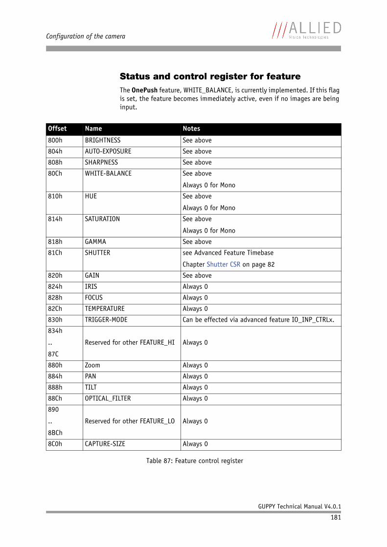
Configuration of the camera
GUPPY Technical Manual V4.0.1
181
Status and control register for featureThe OnePush feature, WHITE_BALANCE, is currently implemented. If this flag is set, the feature becomes immediately active, even if no images are being input.
Offset Name Notes
800h BRIGHTNESS See above
804h AUTO-EXPOSURE See above
808h SHARPNESS See above
80Ch WHITE-BALANCE See above
Always 0 for Mono
810h HUE See above
Always 0 for Mono
814h SATURATION See above
Always 0 for Mono
818h GAMMA See above
81Ch SHUTTER see Advanced Feature Timebase
Chapter Shutter CSR on page 82
820h GAIN See above
824h IRIS Always 0
828h FOCUS Always 0
82Ch TEMPERATURE Always 0
830h TRIGGER-MODE Can be effected via advanced feature IO_INP_CTRLx.
834h
..
87C
Reserved for other FEATURE_HI Always 0
880h Zoom Always 0
884h PAN Always 0
888h TILT Always 0
88Ch OPTICAL_FILTER Always 0
890
..
8BCh
Reserved for other FEATURE_LO Always 0
8C0h CAPTURE-SIZE Always 0
Table 87: Feature control register
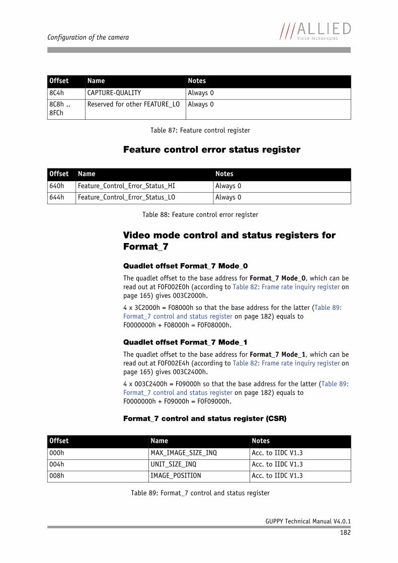
Configuration of the camera
GUPPY Technical Manual V4.0.1
182
Feature control error status register
Video mode control and status registers for Format_7
Quadlet offset Format_7 Mode_0
The quadlet offset to the base address for Format_7 Mode_0, which can be read out at F0F002E0h (according to Table 82: Frame rate inquiry register on page 165) gives 003C2000h.
4 x 3C2000h = F08000h so that the base address for the latter (Table 89: Format_7 control and status register on page 182) equals toF0000000h + F08000h = F0F08000h.
Quadlet offset Format_7 Mode_1
The quadlet offset to the base address for Format_7 Mode_1, which can be read out at F0F002E4h (according to Table 82: Frame rate inquiry register on page 165) gives 003C2400h.
4 x 003C2400h = F09000h so that the base address for the latter (Table 89: Format_7 control and status register on page 182) equals toF0000000h + F09000h = F0F09000h.
Format_7 control and status register (CSR)
8C4h CAPTURE-QUALITY Always 0
8C8h .. 8FCh
Reserved for other FEATURE_LO Always 0
Offset Name Notes
640h Feature_Control_Error_Status_HI Always 0
644h Feature_Control_Error_Status_LO Always 0
Table 88: Feature control error register
Offset Name Notes
000h MAX_IMAGE_SIZE_INQ Acc. to IIDC V1.3
004h UNIT_SIZE_INQ Acc. to IIDC V1.3
008h IMAGE_POSITION Acc. to IIDC V1.3
Table 89: Format_7 control and status register
Offset Name Notes
Table 87: Feature control register
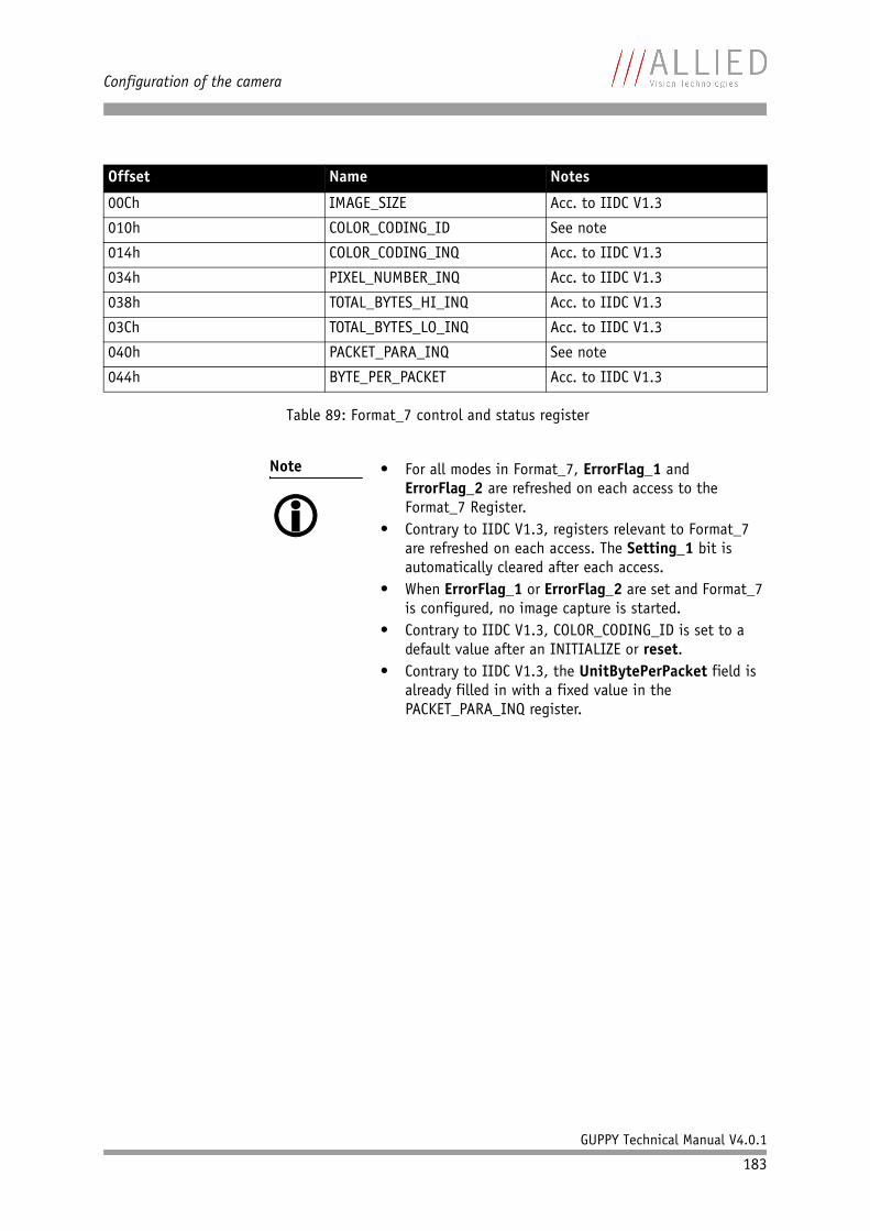
Configuration of the camera
GUPPY Technical Manual V4.0.1
183
00Ch IMAGE_SIZE Acc. to IIDC V1.3
010h COLOR_CODING_ID See note
014h COLOR_CODING_INQ Acc. to IIDC V1.3
034h PIXEL_NUMBER_INQ Acc. to IIDC V1.3
038h TOTAL_BYTES_HI_INQ Acc. to IIDC V1.3
03Ch TOTAL_BYTES_LO_INQ Acc. to IIDC V1.3
040h PACKET_PARA_INQ See note
044h BYTE_PER_PACKET Acc. to IIDC V1.3
Note • For all modes in Format_7, ErrorFlag_1 and ErrorFlag_2 are refreshed on each access to the Format_7 Register.
• Contrary to IIDC V1.3, registers relevant to Format_7 are refreshed on each access. The Setting_1 bit is automatically cleared after each access.
• When ErrorFlag_1 or ErrorFlag_2 are set and Format_7 is configured, no image capture is started.
• Contrary to IIDC V1.3, COLOR_CODING_ID is set to a default value after an INITIALIZE or reset.
• Contrary to IIDC V1.3, the UnitBytePerPacket field is already filled in with a fixed value in the PACKET_PARA_INQ register.
Offset Name Notes
Table 89: Format_7 control and status register
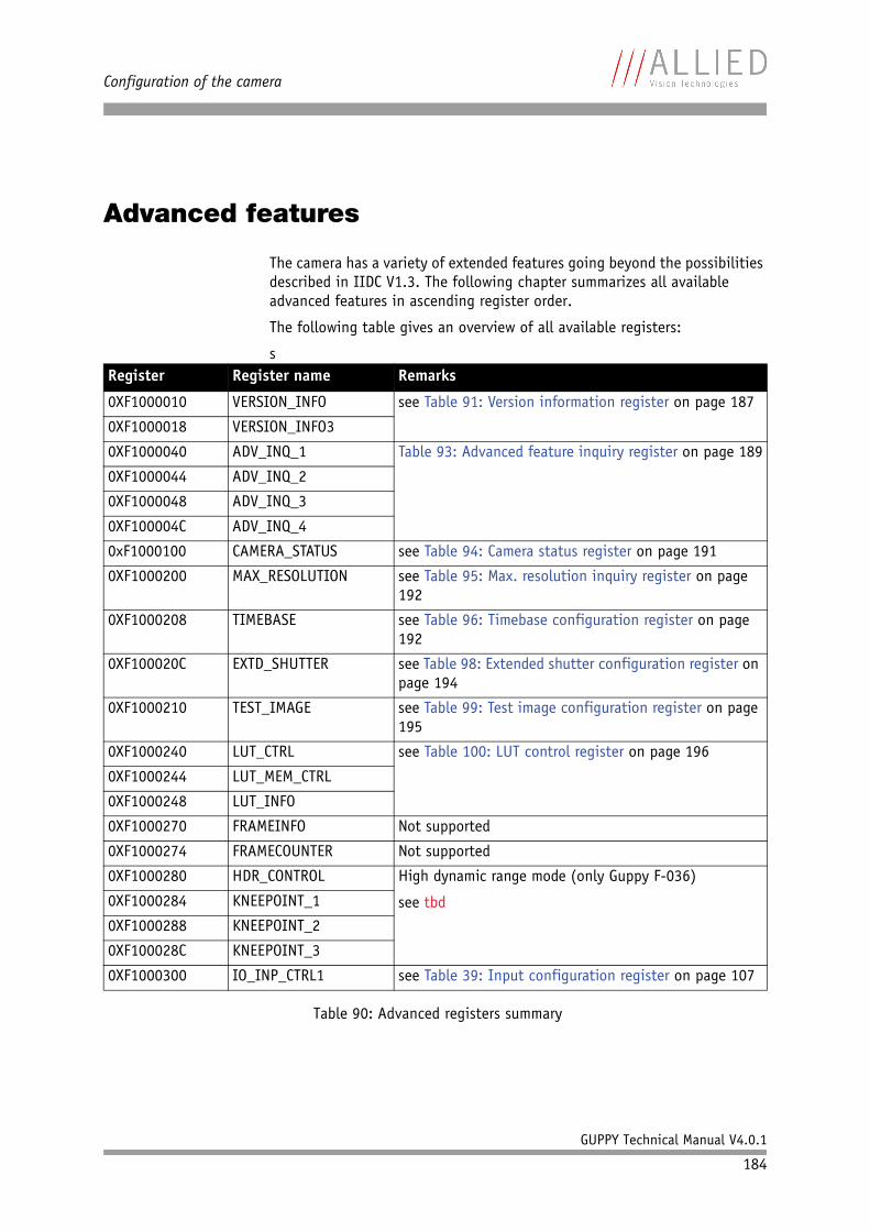
Configuration of the camera
GUPPY Technical Manual V4.0.1
184
Advanced features
The camera has a variety of extended features going beyond the possibilities described in IIDC V1.3. The following chapter summarizes all available advanced features in ascending register order.
The following table gives an overview of all available registers:
sRegister Register name Remarks
0XF1000010 VERSION_INFO see Table 91: Version information register on page 187
0XF1000018 VERSION_INFO3
0XF1000040 ADV_INQ_1 Table 93: Advanced feature inquiry register on page 189
0XF1000044 ADV_INQ_2
0XF1000048 ADV_INQ_3
0XF100004C ADV_INQ_4
0xF1000100 CAMERA_STATUS see Table 94: Camera status register on page 191
0XF1000200 MAX_RESOLUTION see Table 95: Max. resolution inquiry register on page 192
0XF1000208 TIMEBASE see Table 96: Timebase configuration register on page 192
0XF100020C EXTD_SHUTTER see Table 98: Extended shutter configuration register on page 194
0XF1000210 TEST_IMAGE see Table 99: Test image configuration register on page 195
0XF1000240 LUT_CTRL see Table 100: LUT control register on page 196
0XF1000244 LUT_MEM_CTRL
0XF1000248 LUT_INFO
0XF1000270 FRAMEINFO Not supported
0XF1000274 FRAMECOUNTER Not supported
0XF1000280 HDR_CONTROL High dynamic range mode (only Guppy F-036)
see tbd0XF1000284 KNEEPOINT_1
0XF1000288 KNEEPOINT_2
0XF100028C KNEEPOINT_3
0XF1000300 IO_INP_CTRL1 see Table 39: Input configuration register on page 107
Table 90: Advanced registers summary
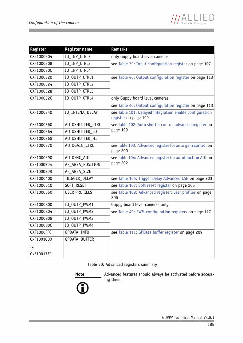
Configuration of the camera
GUPPY Technical Manual V4.0.1
185
0XF1000304 IO_INP_CTRL2 only Guppy board level cameras
see Table 39: Input configuration register on page 1070XF1000308 IO_INP_CTRL3
0XF100030C IO_INP_CTRL4
0XF1000320 IO_OUTP_CTRL1 see Table 46: Output configuration register on page 113
0XF1000324 IO_OUTP_CTRL2
0XF1000328 IO_OUTP_CTRL3
0XF100032C IO_OUTP_CTRL4 only Guppy board level cameras
see Table 46: Output configuration register on page 113
0XF1000340 IO_INTENA_DELAY see Table 101: Delayed integration enable configuration register on page 199
0XF1000360 AUTOSHUTTER_CTRL see Table 102: Auto shutter control advanced register on page 1990XF1000364 AUTOSHUTTER_LO
0XF1000368 AUTOSHUTTER_HI
0XF1000370 AUTOGAIN_CTRL see Table 103: Advanced register for auto gain control on page 200
0XF1000390 AUTOFNC_AOI see Table 104: Advanced register for autofunction AOI on page 2020xF1000394 AF_AREA_POSITION
0xF1000398 AF_AREA_SIZE
0XF1000400 TRIGGER_DELAY see Table 105: Trigger Delay Advanced CSR on page 203
0XF1000510 SOFT_RESET see Table 107: Soft reset register on page 205
0XF1000550 USER PROFILES see Table 108: Advanced register: user profiles on page 206
0XF1000800 IO_OUTP_PWM1 Guppy board level cameras only
see Table 49: PWM configuration registers on page 1170XF1000804 IO_OUTP_PWM2
0XF1000808 IO_OUTP_PWM3
0XF100080C IO_OUTP_PWM4
0XF1000FFC GPDATA_INFO see Table 111: GPData buffer register on page 209
0xF1001000
…
0xF10017FC
GPDATA_BUFFER
Note Advanced features should always be activated before access-ing them.
Register Register name Remarks
Table 90: Advanced registers summary

Configuration of the camera
GUPPY Technical Manual V4.0.1
186
Note • Currently all registers can be written without being activated. This makes it easier to operate the camera using Directcontrol.
• AVT reserves the right to require activation in future versions of the software.
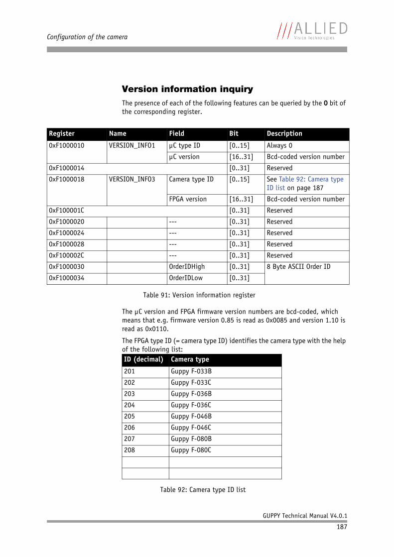
Configuration of the camera
GUPPY Technical Manual V4.0.1
187
Version information inquiryThe presence of each of the following features can be queried by the 0 bit of the corresponding register.
The µC version and FPGA firmware version numbers are bcd-coded, which means that e.g. firmware version 0.85 is read as 0x0085 and version 1.10 is read as 0x0110.
The FPGA type ID (= camera type ID) identifies the camera type with the help of the following list:
Register Name Field Bit Description
0xF1000010 VERSION_INFO1 µC type ID [0..15] Always 0
µC version [16..31] Bcd-coded version number
0xF1000014 [0..31] Reserved
0xF1000018 VERSION_INFO3 Camera type ID [0..15] See Table 92: Camera type ID list on page 187
FPGA version [16..31] Bcd-coded version number
0xF100001C [0..31] Reserved
0xF1000020 --- [0..31] Reserved
0xF1000024 --- [0..31] Reserved
0xF1000028 --- [0..31] Reserved
0xF100002C --- [0..31] Reserved
0xF1000030 OrderIDHigh [0..31] 8 Byte ASCII Order ID
0xF1000034 OrderIDLow [0..31]
Table 91: Version information register
ID (decimal) Camera type
201 Guppy F-033B
202 Guppy F-033C
203 Guppy F-036B
204 Guppy F-036C
205 Guppy F-046B
206 Guppy F-046C
207 Guppy F-080B
208 Guppy F-080C
Table 92: Camera type ID list
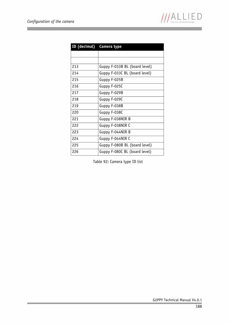
Configuration of the camera
GUPPY Technical Manual V4.0.1
188
213 Guppy F-033B BL (board level)
214 Guppy F-033C BL (board level)
215 Guppy F-025B
216 Guppy F-025C
217 Guppy F-029B
218 Guppy F-029C
219 Guppy F-038B
220 Guppy F-038C
221 Guppy F-038NIR B
222 Guppy F-038NIR C
223 Guppy F-044NIR B
224 Guppy F-044NIR C
225 Guppy F-080B BL (board level)
226 Guppy F-080C BL (board level)
ID (decimal) Camera type
Table 92: Camera type ID list
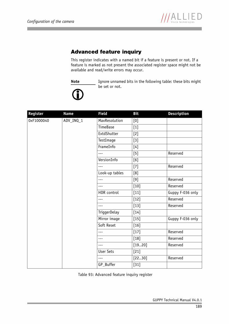
Configuration of the camera
GUPPY Technical Manual V4.0.1
189
Advanced feature inquiryThis register indicates with a named bit if a feature is present or not. If a feature is marked as not present the associated register space might not be available and read/write errors may occur.
Note Ignore unnamed bits in the following table: these bits might be set or not.
Register Name Field Bit Description
0xF1000040 ADV_INQ_1 MaxResolution [0]
TimeBase [1]
ExtdShutter [2]
TestImage [3]
FrameInfo [4]
--- [5] Reserved
VersionInfo [6]
--- [7] Reserved
Look-up tables [8]
--- [9] Reserved
--- [10] Reserved
HDR control [11] Guppy F-036 only
--- [12] Reserved
--- [13] Reserved
TriggerDelay [14]
Mirror image [15] Guppy F-036 only
Soft Reset [16]
--- [17] Reserved
--- [18] Reserved
--- [19..20] Reserved
User Sets [21]
--- [22..30] Reserved
GP_Buffer [31]
Table 93: Advanced feature inquiry register
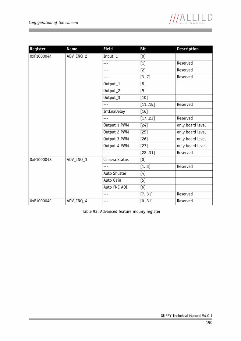
Configuration of the camera
GUPPY Technical Manual V4.0.1
190
0xF1000044 ADV_INQ_2 Input_1 [0]
--- [1] Reserved
--- [2] Reserved
--- [3..7] Reserved
Output_1 [8]
Output_2 [9]
Output_3 [10]
--- [11..15] Reserved
IntEnaDelay [16]
--- [17..23] Reserved
Output 1 PWM [24] only board level
Output 2 PWM [25] only board level
Output 3 PWM [26] only board level
Output 4 PWM [27] only board level
--- [28..31] Reserved
0xF1000048 ADV_INQ_3 Camera Status [0]
--- [1..3] Reserved
Auto Shutter [4]
Auto Gain [5]
Auto FNC AOI [6]
--- [7..31] Reserved
0xF100004C ADV_INQ_4 --- [0..31] Reserved
Register Name Field Bit Description
Table 93: Advanced feature inquiry register
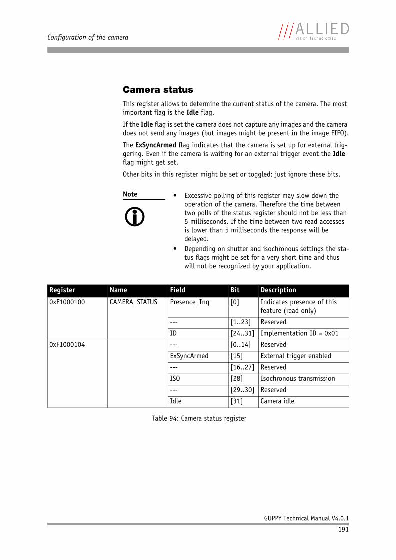
Configuration of the camera
GUPPY Technical Manual V4.0.1
191
Camera statusThis register allows to determine the current status of the camera. The most important flag is the Idle flag.
If the Idle flag is set the camera does not capture any images and the camera does not send any images (but images might be present in the image FIFO).
The ExSyncArmed flag indicates that the camera is set up for external trig-gering. Even if the camera is waiting for an external trigger event the Idle flag might get set.
Other bits in this register might be set or toggled: just ignore these bits.
Note • Excessive polling of this register may slow down the operation of the camera. Therefore the time between two polls of the status register should not be less than 5 milliseconds. If the time between two read accesses is lower than 5 milliseconds the response will be delayed.
• Depending on shutter and isochronous settings the sta-tus flags might be set for a very short time and thus will not be recognized by your application.
Register Name Field Bit Description
0xF1000100 CAMERA_STATUS Presence_Inq [0] Indicates presence of this feature (read only)
--- [1..23] Reserved
ID [24..31] Implementation ID = 0x01
0xF1000104 --- [0..14] Reserved
ExSyncArmed [15] External trigger enabled
--- [16..27] Reserved
ISO [28] Isochronous transmission
--- [29..30] Reserved
Idle [31] Camera idle
Table 94: Camera status register
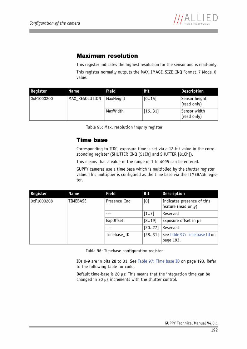
Configuration of the camera
GUPPY Technical Manual V4.0.1
192
Maximum resolutionThis register indicates the highest resolution for the sensor and is read-only.
This register normally outputs the MAX_IMAGE_SIZE_INQ Format_7 Mode_0 value.
Time baseCorresponding to IIDC, exposure time is set via a 12-bit value in the corre-sponding register (SHUTTER_INQ [51Ch] and SHUTTER [81Ch]).
This means that a value in the range of 1 to 4095 can be entered.
GUPPY cameras use a time base which is multiplied by the shutter register value. This multiplier is configured as the time base via the TIMEBASE regis-ter.
IDs 0-9 are in bits 28 to 31. See Table 97: Time base ID on page 193. Refer to the following table for code.
Default time-base is 20 µs: This means that the integration time can be changed in 20 µs increments with the shutter control.
Register Name Field Bit Description
0xF1000200 MAX_RESOLUTION MaxHeight [0..15] Sensor height(read only)
MaxWidth [16..31] Sensor width(read only)
Table 95: Max. resolution inquiry register
Register Name Field Bit Description
0xF1000208 TIMEBASE Presence_Inq [0] Indicates presence of this feature (read only)
--- [1..7] Reserved
ExpOffset [8..19] Exposure offset in µs
--- [20..27] Reserved
Timebase_ID [28..31] See Table 97: Time base ID on page 193.
Table 96: Timebase configuration register
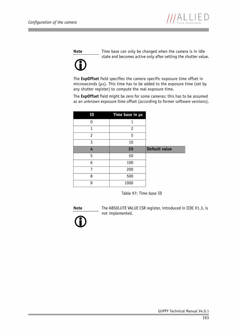
Configuration of the camera
GUPPY Technical Manual V4.0.1
193
The ExpOffset field specifies the camera specific exposure time offset in microseconds (µs). This time has to be added to the exposure time (set by any shutter register) to compute the real exposure time.
The ExpOffset field might be zero for some cameras: this has to be assumed as an unknown exposure time offset (according to former software versions).
Note Time base can only be changed when the camera is in idle state and becomes active only after setting the shutter value.
ID Time base in µs
0 1
1 2
2 5
3 10
4 20 Default value
5 50
6 100
7 200
8 500
9 1000
Table 97: Time base ID
Note The ABSOLUTE VALUE CSR register, introduced in IIDC V1.3, is not implemented.
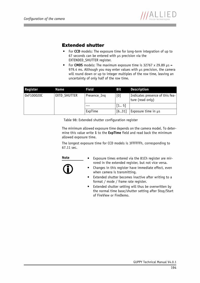
Configuration of the camera
GUPPY Technical Manual V4.0.1
194
Extended shutter• For CCD models: The exposure time for long-term integration of up to
67 seconds can be entered with µs precision via the EXTENDED_SHUTTER register.
• For CMOS models: The maximum exposure time is 32767 x 29.89 µs = 979.4 ms. Although you may enter values with µs precision, the camera will round down or up to integer multiples of the row time, leaving an uncertainty of only half of the row time.
The minimum allowed exposure time depends on the camera model. To deter-mine this value write 1 to the ExpTime field and read back the minimum allowed exposure time.
The longest exposure time for CCD models is 3FFFFFFh, corresponding to 67.11 sec.
Register Name Field Bit Description
0xF100020C EXTD_SHUTTER Presence_Inq [0] Indicates presence of this fea-ture (read only)
--- [1.. 5]
ExpTime [6..31] Exposure time in µs
Table 98: Extended shutter configuration register
Note • Exposure times entered via the 81Ch register are mir-rored in the extended register, but not vice versa.
• Changes in this register have immediate effect, even when camera is transmitting.
• Extended shutter becomes inactive after writing to a format / mode / frame rate register.
• Extended shutter setting will thus be overwritten by the normal time base/shutter setting after Stop/Start of FireView or FireDemo.
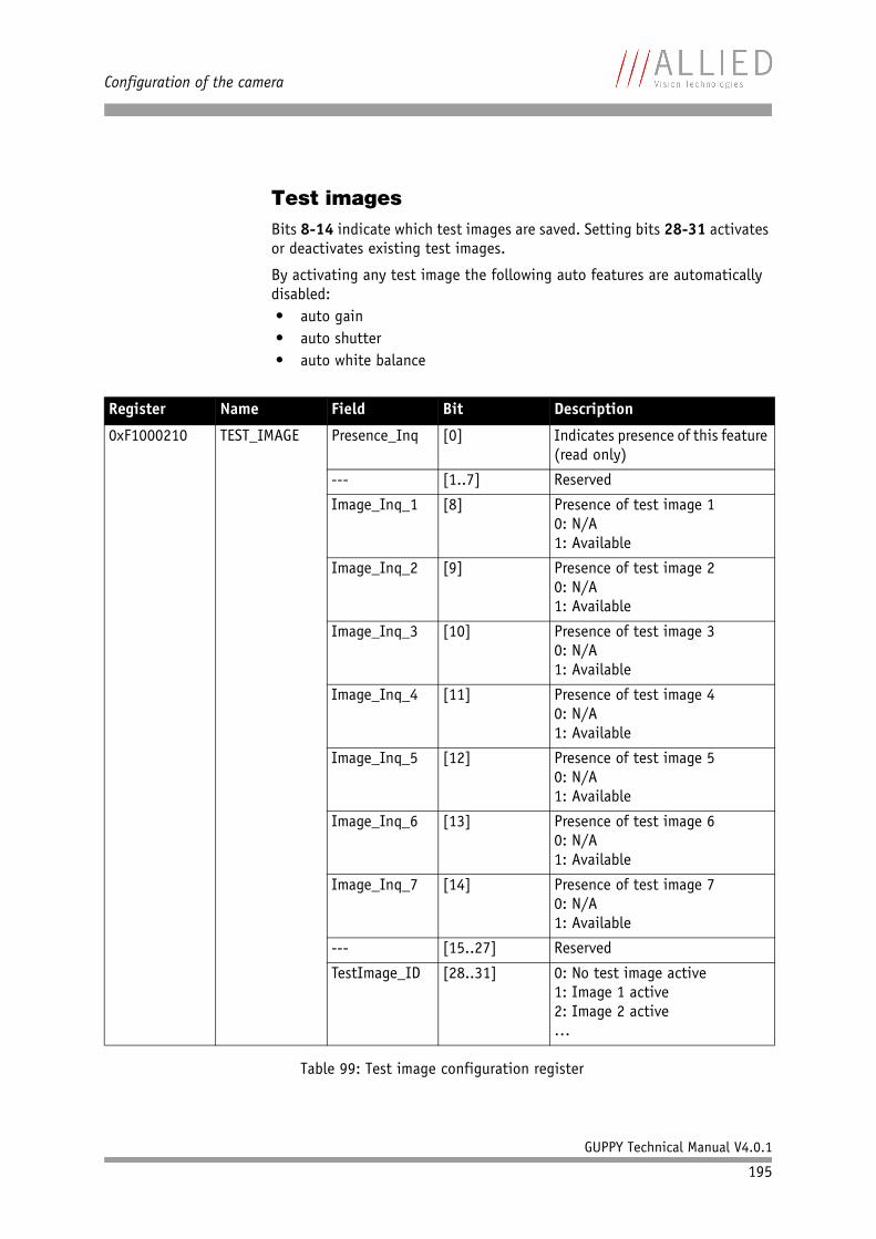
Configuration of the camera
GUPPY Technical Manual V4.0.1
195
Test imagesBits 8-14 indicate which test images are saved. Setting bits 28-31 activates or deactivates existing test images.
By activating any test image the following auto features are automatically disabled:• auto gain• auto shutter• auto white balance
Register Name Field Bit Description
0xF1000210 TEST_IMAGE Presence_Inq [0] Indicates presence of this feature (read only)
--- [1..7] Reserved
Image_Inq_1 [8] Presence of test image 10: N/A1: Available
Image_Inq_2 [9] Presence of test image 20: N/A1: Available
Image_Inq_3 [10] Presence of test image 30: N/A1: Available
Image_Inq_4 [11] Presence of test image 40: N/A1: Available
Image_Inq_5 [12] Presence of test image 50: N/A1: Available
Image_Inq_6 [13] Presence of test image 60: N/A1: Available
Image_Inq_7 [14] Presence of test image 70: N/A1: Available
--- [15..27] Reserved
TestImage_ID [28..31] 0: No test image active1: Image 1 active2: Image 2 active…
Table 99: Test image configuration register
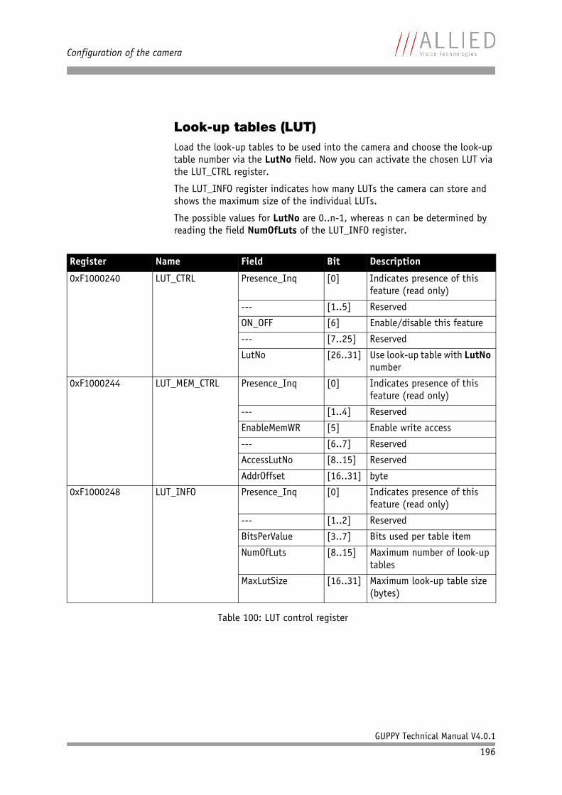
Configuration of the camera
GUPPY Technical Manual V4.0.1
196
Look-up tables (LUT)Load the look-up tables to be used into the camera and choose the look-up table number via the LutNo field. Now you can activate the chosen LUT via the LUT_CTRL register.
The LUT_INFO register indicates how many LUTs the camera can store and shows the maximum size of the individual LUTs.
The possible values for LutNo are 0..n-1, whereas n can be determined by reading the field NumOfLuts of the LUT_INFO register.
Register Name Field Bit Description
0xF1000240 LUT_CTRL Presence_Inq [0] Indicates presence of this feature (read only)
--- [1..5] Reserved
ON_OFF [6] Enable/disable this feature
--- [7..25] Reserved
LutNo [26..31] Use look-up table with LutNo number
0xF1000244 LUT_MEM_CTRL Presence_Inq [0] Indicates presence of this feature (read only)
--- [1..4] Reserved
EnableMemWR [5] Enable write access
--- [6..7] Reserved
AccessLutNo [8..15] Reserved
AddrOffset [16..31] byte
0xF1000248 LUT_INFO Presence_Inq [0] Indicates presence of this feature (read only)
--- [1..2] Reserved
BitsPerValue [3..7] Bits used per table item
NumOfLuts [8..15] Maximum number of look-up tables
MaxLutSize [16..31] Maximum look-up table size (bytes)
Table 100: LUT control register
Configuration of the camera
GUPPY Technical Manual V4.0.1
197
Note The BitsPerValue field indicates how many bits are read from the LUT for any gray-value read from the sensor. To determine the number of bytes occupied for each gray-value round-up the BitsPerValue field to the next byte boundary.
Examples:
• BitsPerValue = 8 1 byte per gray-value• BitsPerValue = 14 2 byte per gray-valueDivide MaxLutSize by the number of bytes per gray-value in order to get the number of bits read from the sensor.
Note Guppy cameras have the gamma feature implemented via a built-in look-up table. Therefore you can not use gamma and your own look-up table at the same time. Nevertheless you may combine a gamma look-up table into your own look-up table.
Note When using the LUT feature and the gamma feature pay attention to the following:
• gamma ON look-up table is switched ON also• gamma OFF look-up table is switched OFF also• look-up table OFF gamma is switched OFF also• look-up table ON gamma is switched OFF
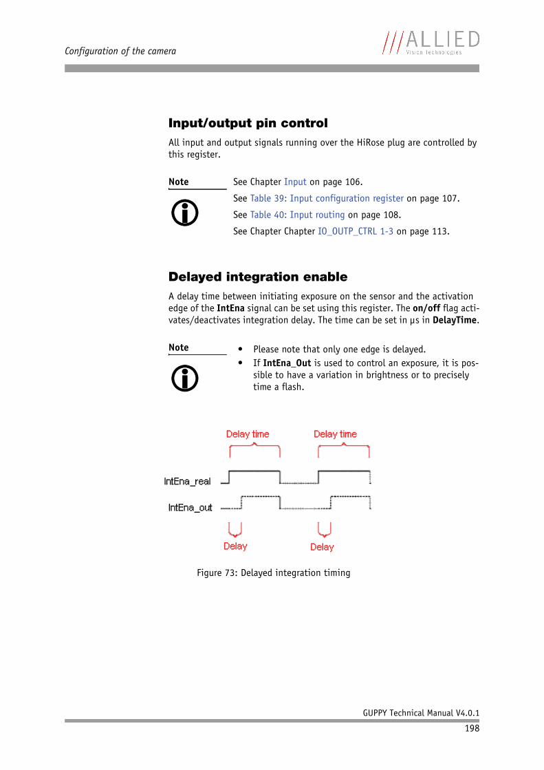
Configuration of the camera
GUPPY Technical Manual V4.0.1
198
Input/output pin controlAll input and output signals running over the HiRose plug are controlled by this register.
Delayed integration enableA delay time between initiating exposure on the sensor and the activation edge of the IntEna signal can be set using this register. The on/off flag acti-vates/deactivates integration delay. The time can be set in µs in DelayTime.
Note See Chapter Input on page 106.
See Table 39: Input configuration register on page 107.
See Table 40: Input routing on page 108.
See Chapter Chapter IO_OUTP_CTRL 1-3 on page 113.
Note • Please note that only one edge is delayed.• If IntEna_Out is used to control an exposure, it is pos-
sible to have a variation in brightness or to precisely time a flash.
Figure 73: Delayed integration timing
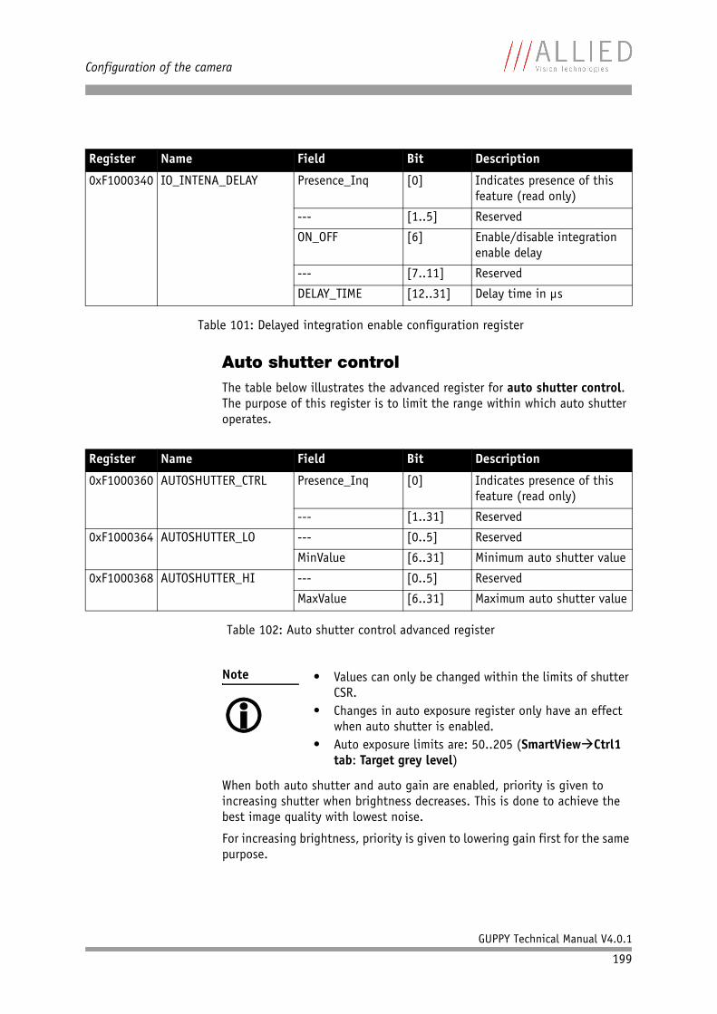
Configuration of the camera
GUPPY Technical Manual V4.0.1
199
Auto shutter controlThe table below illustrates the advanced register for auto shutter control. The purpose of this register is to limit the range within which auto shutter operates.
When both auto shutter and auto gain are enabled, priority is given to increasing shutter when brightness decreases. This is done to achieve the best image quality with lowest noise.
For increasing brightness, priority is given to lowering gain first for the same purpose.
Register Name Field Bit Description
0xF1000340 IO_INTENA_DELAY Presence_Inq [0] Indicates presence of this feature (read only)
--- [1..5] Reserved
ON_OFF [6] Enable/disable integration enable delay
--- [7..11] Reserved
DELAY_TIME [12..31] Delay time in µs
Table 101: Delayed integration enable configuration register
Register Name Field Bit Description
0xF1000360 AUTOSHUTTER_CTRL Presence_Inq [0] Indicates presence of this feature (read only)
--- [1..31] Reserved
0xF1000364 AUTOSHUTTER_LO --- [0..5] Reserved
MinValue [6..31] Minimum auto shutter value
0xF1000368 AUTOSHUTTER_HI --- [0..5] Reserved
MaxValue [6..31] Maximum auto shutter value
Table 102: Auto shutter control advanced register
Note • Values can only be changed within the limits of shutter CSR.
• Changes in auto exposure register only have an effect when auto shutter is enabled.
• Auto exposure limits are: 50..205 (SmartView Ctrl1 tab: Target grey level)
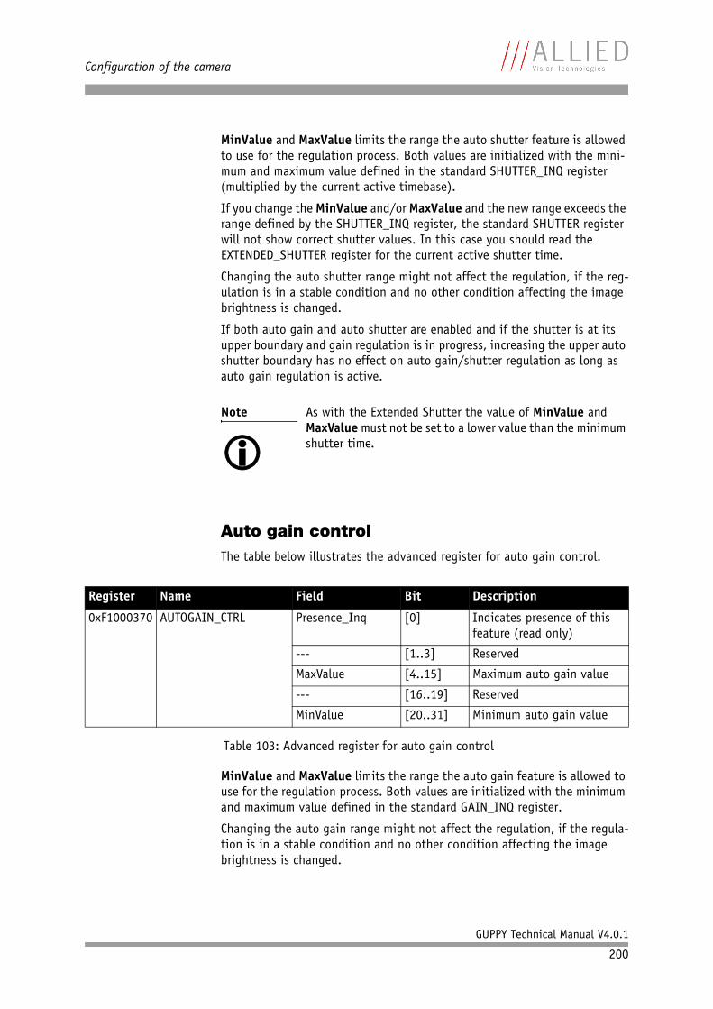
Configuration of the camera
GUPPY Technical Manual V4.0.1
200
MinValue and MaxValue limits the range the auto shutter feature is allowed to use for the regulation process. Both values are initialized with the mini-mum and maximum value defined in the standard SHUTTER_INQ register (multiplied by the current active timebase).
If you change the MinValue and/or MaxValue and the new range exceeds the range defined by the SHUTTER_INQ register, the standard SHUTTER register will not show correct shutter values. In this case you should read the EXTENDED_SHUTTER register for the current active shutter time.
Changing the auto shutter range might not affect the regulation, if the reg-ulation is in a stable condition and no other condition affecting the image brightness is changed.
If both auto gain and auto shutter are enabled and if the shutter is at its upper boundary and gain regulation is in progress, increasing the upper auto shutter boundary has no effect on auto gain/shutter regulation as long as auto gain regulation is active.
Auto gain controlThe table below illustrates the advanced register for auto gain control.
MinValue and MaxValue limits the range the auto gain feature is allowed to use for the regulation process. Both values are initialized with the minimum and maximum value defined in the standard GAIN_INQ register.
Changing the auto gain range might not affect the regulation, if the regula-tion is in a stable condition and no other condition affecting the image brightness is changed.
Note As with the Extended Shutter the value of MinValue and MaxValue must not be set to a lower value than the minimum shutter time.
Register Name Field Bit Description
0xF1000370 AUTOGAIN_CTRL Presence_Inq [0] Indicates presence of this feature (read only)
--- [1..3] Reserved
MaxValue [4..15] Maximum auto gain value
--- [16..19] Reserved
MinValue [20..31] Minimum auto gain value
Table 103: Advanced register for auto gain control
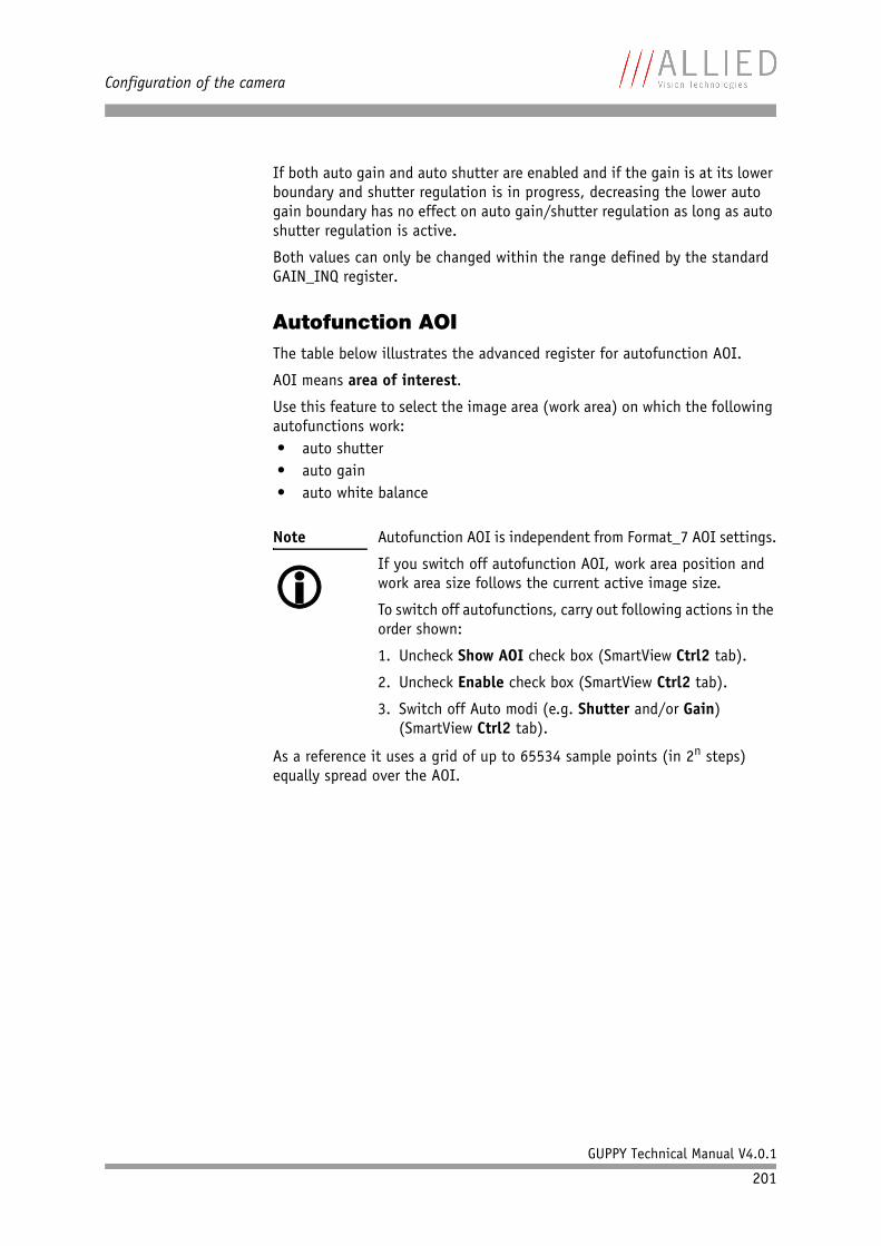
Configuration of the camera
GUPPY Technical Manual V4.0.1
201
If both auto gain and auto shutter are enabled and if the gain is at its lower boundary and shutter regulation is in progress, decreasing the lower auto gain boundary has no effect on auto gain/shutter regulation as long as auto shutter regulation is active.
Both values can only be changed within the range defined by the standard GAIN_INQ register.
Autofunction AOIThe table below illustrates the advanced register for autofunction AOI.
AOI means area of interest.
Use this feature to select the image area (work area) on which the following autofunctions work:• auto shutter• auto gain• auto white balance
As a reference it uses a grid of up to 65534 sample points (in 2n steps) equally spread over the AOI.
Note Autofunction AOI is independent from Format_7 AOI settings.
If you switch off autofunction AOI, work area position and work area size follows the current active image size.
To switch off autofunctions, carry out following actions in the order shown:
1. Uncheck Show AOI check box (SmartView Ctrl2 tab).
2. Uncheck Enable check box (SmartView Ctrl2 tab).
3. Switch off Auto modi (e.g. Shutter and/or Gain) (SmartView Ctrl2 tab).
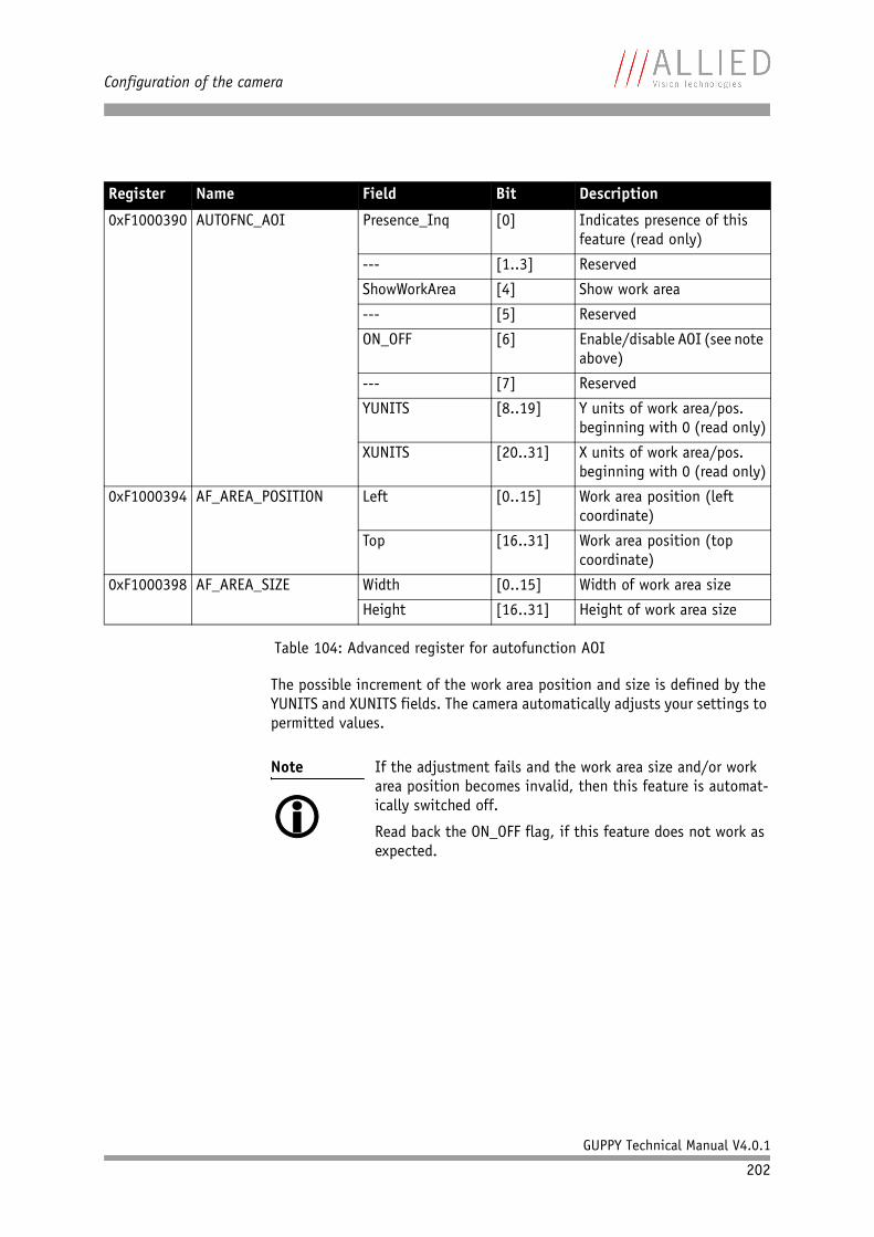
Configuration of the camera
GUPPY Technical Manual V4.0.1
202
The possible increment of the work area position and size is defined by the YUNITS and XUNITS fields. The camera automatically adjusts your settings to permitted values.
Register Name Field Bit Description
0xF1000390 AUTOFNC_AOI Presence_Inq [0] Indicates presence of this feature (read only)
--- [1..3] Reserved
ShowWorkArea [4] Show work area
--- [5] Reserved
ON_OFF [6] Enable/disable AOI (see note above)
--- [7] Reserved
YUNITS [8..19] Y units of work area/pos. beginning with 0 (read only)
XUNITS [20..31] X units of work area/pos. beginning with 0 (read only)
0xF1000394 AF_AREA_POSITION Left [0..15] Work area position (left coordinate)
Top [16..31] Work area position (top coordinate)
0xF1000398 AF_AREA_SIZE Width [0..15] Width of work area size
Height [16..31] Height of work area size
Table 104: Advanced register for autofunction AOI
Note If the adjustment fails and the work area size and/or work area position becomes invalid, then this feature is automat-ically switched off.
Read back the ON_OFF flag, if this feature does not work as expected.
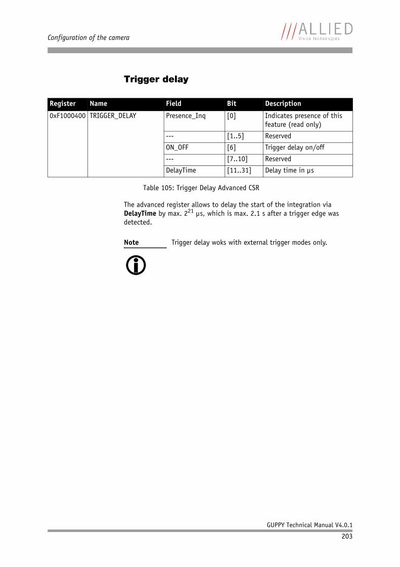
Configuration of the camera
GUPPY Technical Manual V4.0.1
203
Trigger delay
The advanced register allows to delay the start of the integration via DelayTime by max. 221 µs, which is max. 2.1 s after a trigger edge was detected.
Register Name Field Bit Description
0xF1000400 TRIGGER_DELAY Presence_Inq [0] Indicates presence of this feature (read only)
--- [1..5] Reserved
ON_OFF [6] Trigger delay on/off
--- [7..10] Reserved
DelayTime [11..31] Delay time in µs
Table 105: Trigger Delay Advanced CSR
Note Trigger delay woks with external trigger modes only.
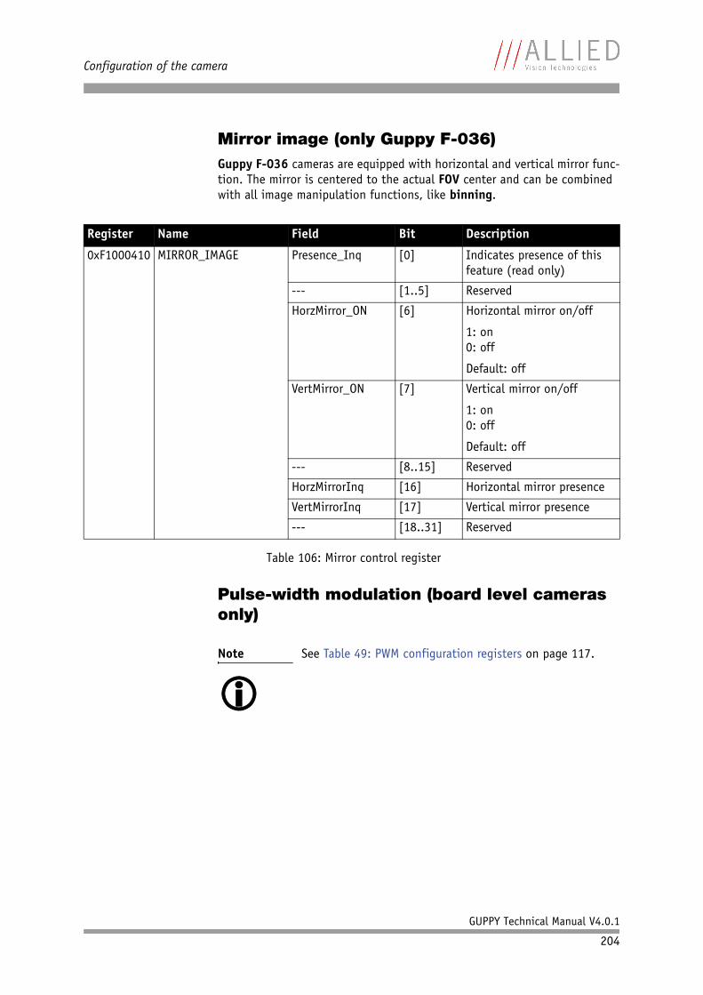
Configuration of the camera
GUPPY Technical Manual V4.0.1
204
Mirror image (only Guppy F-036)Guppy F-036 cameras are equipped with horizontal and vertical mirror func-tion. The mirror is centered to the actual FOV center and can be combined with all image manipulation functions, like binning.
Pulse-width modulation (board level cameras only)
Register Name Field Bit Description
0xF1000410 MIRROR_IMAGE Presence_Inq [0] Indicates presence of this feature (read only)
--- [1..5] Reserved
HorzMirror_ON [6] Horizontal mirror on/off
1: on0: off
Default: off
VertMirror_ON [7] Vertical mirror on/off
1: on0: off
Default: off
--- [8..15] Reserved
HorzMirrorInq [16] Horizontal mirror presence
VertMirrorInq [17] Vertical mirror presence
--- [18..31] Reserved
Table 106: Mirror control register
Note See Table 49: PWM configuration registers on page 117.
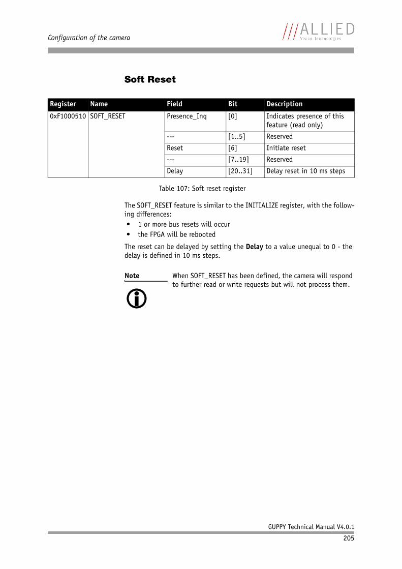
Configuration of the camera
GUPPY Technical Manual V4.0.1
205
Soft Reset
The SOFT_RESET feature is similar to the INITIALIZE register, with the follow-ing differences:• 1 or more bus resets will occur• the FPGA will be rebooted
The reset can be delayed by setting the Delay to a value unequal to 0 - the delay is defined in 10 ms steps.
Register Name Field Bit Description
0xF1000510 SOFT_RESET Presence_Inq [0] Indicates presence of this feature (read only)
--- [1..5] Reserved
Reset [6] Initiate reset
--- [7..19] Reserved
Delay [20..31] Delay reset in 10 ms steps
Table 107: Soft reset register
Note When SOFT_RESET has been defined, the camera will respond to further read or write requests but will not process them.
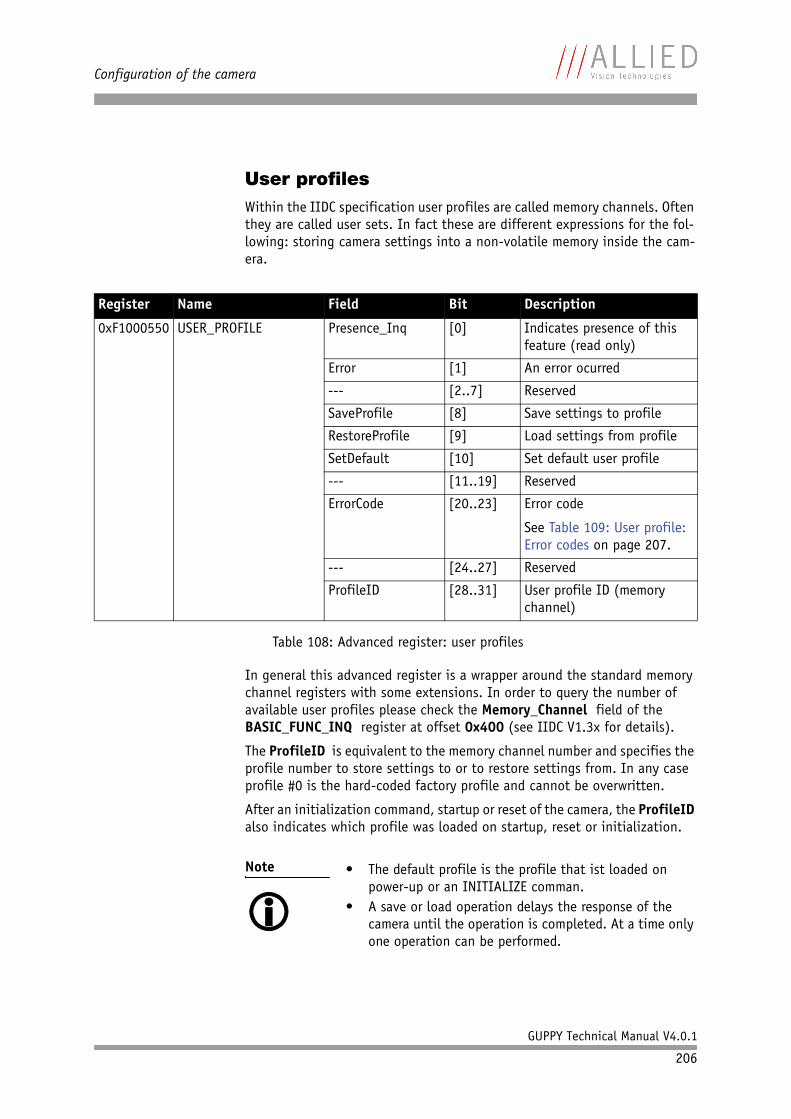
Configuration of the camera
GUPPY Technical Manual V4.0.1
206
User profilesWithin the IIDC specification user profiles are called memory channels. Often they are called user sets. In fact these are different expressions for the fol-lowing: storing camera settings into a non-volatile memory inside the cam-era.
In general this advanced register is a wrapper around the standard memory channel registers with some extensions. In order to query the number of available user profiles please check the Memory_Channel field of the BASIC_FUNC_INQ register at offset 0x400 (see IIDC V1.3x for details).
The ProfileID is equivalent to the memory channel number and specifies the profile number to store settings to or to restore settings from. In any case profile #0 is the hard-coded factory profile and cannot be overwritten.
After an initialization command, startup or reset of the camera, the ProfileID also indicates which profile was loaded on startup, reset or initialization.
Register Name Field Bit Description
0xF1000550 USER_PROFILE Presence_Inq [0] Indicates presence of this feature (read only)
Error [1] An error ocurred
--- [2..7] Reserved
SaveProfile [8] Save settings to profile
RestoreProfile [9] Load settings from profile
SetDefault [10] Set default user profile
--- [11..19] Reserved
ErrorCode [20..23] Error code
See Table 109: User profile: Error codes on page 207.
--- [24..27] Reserved
ProfileID [28..31] User profile ID (memory channel)
Table 108: Advanced register: user profiles
Note • The default profile is the profile that ist loaded on power-up or an INITIALIZE comman.
• A save or load operation delays the response of the camera until the operation is completed. At a time only one operation can be performed.
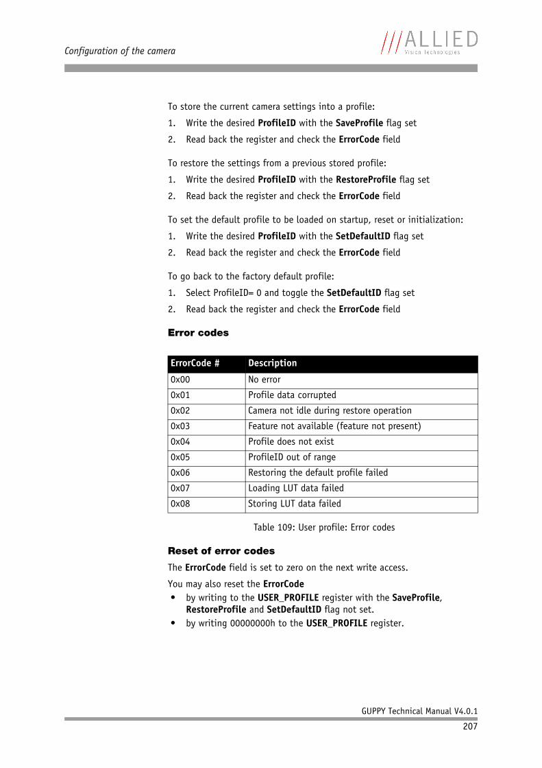
Configuration of the camera
GUPPY Technical Manual V4.0.1
207
To store the current camera settings into a profile:
1. Write the desired ProfileID with the SaveProfile flag set
2. Read back the register and check the ErrorCode field
To restore the settings from a previous stored profile:
1. Write the desired ProfileID with the RestoreProfile flag set
2. Read back the register and check the ErrorCode field
To set the default profile to be loaded on startup, reset or initialization:
1. Write the desired ProfileID with the SetDefaultID flag set
2. Read back the register and check the ErrorCode field
To go back to the factory default profile:
1. Select ProfileID= 0 and toggle the SetDefaultID flag set
2. Read back the register and check the ErrorCode field
Error codes
Reset of error codes
The ErrorCode field is set to zero on the next write access.
You may also reset the ErrorCode• by writing to the USER_PROFILE register with the SaveProfile,
RestoreProfile and SetDefaultID flag not set.• by writing 00000000h to the USER_PROFILE register.
ErrorCode # Description
0x00 No error
0x01 Profile data corrupted
0x02 Camera not idle during restore operation
0x03 Feature not available (feature not present)
0x04 Profile does not exist
0x05 ProfileID out of range
0x06 Restoring the default profile failed
0x07 Loading LUT data failed
0x08 Storing LUT data failed
Table 109: User profile: Error codes
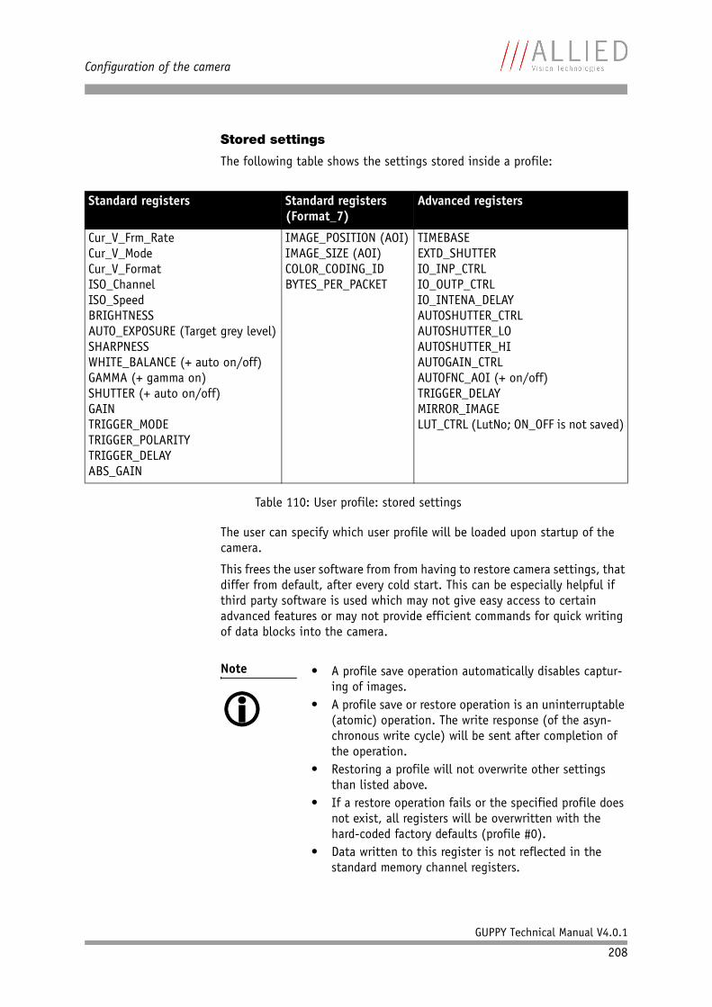
Configuration of the camera
GUPPY Technical Manual V4.0.1
208
Stored settings
The following table shows the settings stored inside a profile:
The user can specify which user profile will be loaded upon startup of the camera.
This frees the user software from from having to restore camera settings, that differ from default, after every cold start. This can be especially helpful if third party software is used which may not give easy access to certain advanced features or may not provide efficient commands for quick writing of data blocks into the camera.
Standard registers Standard registers(Format_7)
Advanced registers
Cur_V_Frm_RateCur_V_ModeCur_V_FormatISO_ChannelISO_SpeedBRIGHTNESSAUTO_EXPOSURE (Target grey level)SHARPNESSWHITE_BALANCE (+ auto on/off)GAMMA (+ gamma on)SHUTTER (+ auto on/off)GAINTRIGGER_MODETRIGGER_POLARITYTRIGGER_DELAYABS_GAIN
IMAGE_POSITION (AOI)IMAGE_SIZE (AOI)COLOR_CODING_IDBYTES_PER_PACKET
TIMEBASEEXTD_SHUTTERIO_INP_CTRLIO_OUTP_CTRLIO_INTENA_DELAYAUTOSHUTTER_CTRLAUTOSHUTTER_LOAUTOSHUTTER_HIAUTOGAIN_CTRLAUTOFNC_AOI (+ on/off)TRIGGER_DELAYMIRROR_IMAGELUT_CTRL (LutNo; ON_OFF is not saved)
Table 110: User profile: stored settings
Note • A profile save operation automatically disables captur-ing of images.
• A profile save or restore operation is an uninterruptable (atomic) operation. The write response (of the asyn-chronous write cycle) will be sent after completion of the operation.
• Restoring a profile will not overwrite other settings than listed above.
• If a restore operation fails or the specified profile does not exist, all registers will be overwritten with the hard-coded factory defaults (profile #0).
• Data written to this register is not reflected in the standard memory channel registers.
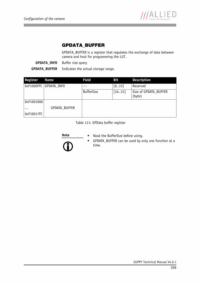
Configuration of the camera
GUPPY Technical Manual V4.0.1
209
GPDATA_BUFFERGPDATA_BUFFER is a register that regulates the exchange of data between camera and host for programming the LUT.
GPDATA_INFO Buffer size query
GPDATA_BUFFER Indicates the actual storage range.
Register Name Field Bit Description
0xF1000FFC GPDATA_INFO --- [0..15] Reserved
BufferSize [16..31] Size of GPDATA_BUFFER (byte)
0xF1001000
…
0xF10017FC
GPDATA_BUFFER
Table 111: GPData buffer register
Note • Read the BufferSize before using.• GPDATA_BUFFER can be used by only one function at a
time.

Firmware update
GUPPY Technical Manual V4.0.1
210
Firmware update
Firmware updates can be carried out without opening the camera.
Note For further information:
• Read the application note: How to update Guppy/Pike firmware at AVT website or
• Contact your local dealer.
Glossary
GUPPY Technical Manual V4.0.1
211
Glossary
4:1:1 YUV4:1:1 is a color mode (see YUV).
Chroma subsampling means that a lower resolution for the color (chroma) information in an image is used than for the brightness (intensity or luma) information.
Because the human eye is less sensitive to color than intensity, the chroma components of an image need not be as well defined as the luma compo-nent, so many video systems sample the color difference channels at a lower definition (i.e., sample frequency) than the brightness. This reduces the overall bandwidth of the video signal without much apparent loss of picture quality. The missing values will be interpolated or repeated from the preceding sample for that channel.
Sampling systems and ratios: The subsampling in a video system is usually expressed as a three part ratio. The three terms of the ratio are: the number of brightness (luminance, luma or Y) samples, followed by the number of samples of the two color (chroma) components: U then V, for each com-plete sample area. For quality comparison, only the ratio between those values is important, so 4:4:4 could easily be called 1:1:1; however, tradi-tionally the value for brightness is always 4, with the rest of the values scaled accordingly.
YUV4:1:1 means: chroma subsampling, the horizontal color resolution is quartered. This is still acceptable for lower-end and consumer applications. Uncompressed video in this format with 8-bit quantization uses 6 bytes for every macropixel (4 pixels in a row).
4:2:2 YUV4:2:2 is a color mode (see YUV).
For detailed explanation of chroma subsampling see 4:1:1.
In YUV4:2:2 color mode each of the two color-difference channels has half the sample rate of the brightness channel, so horizontal color resolution is only half that of 4:4:4.
ADC ADC = analog digital converter
An analog-to-digital converter (abbreviated ADC, A/D, or A to D) is a device that converts continuous signals to discrete digital numbers.
Typically, an ADC converts a voltage to a digital number. A digital-to-analog converter (DAC) performs the reverse operation.
AEC AEC = auto exposure control
Glossary
GUPPY Technical Manual V4.0.1
212
AFE AFE = analog front end
The AFE conditions the analog signal received from the image sensor and performs the analog-to-digital (A/D) conversion.
AGC AGC = auto gain control
AGC means that the electronic amplification of the video signal is automat-ically adjusted to compensate for varying levels of scene illumination.
Aliasing Phenomenon of interference which occurs when a signal being sampled contains frequencies that are higher than half the sampling frequency. Typ-ically can be seen as ragged edges on horizontal lines.
Analog front end see AFE
AOI AOI = area of interest
see area of interest
Area of interest Area of interest readout (AOI) refers to a camera function whereby only a portion of the available pixels are read out from the camera. For example, it is possible to read out a 10 x 20 pixel rectangular area of pixels from a camera that has a total resolution of 648 x 488. The result is a much faster frame rate and less data to be processed. This is also referred to as partial scan. Various autofunctions (auto shutter, auto gain, auto white balance) act on the AOI.
Asynchronous shutter The camera CCD starts to accumulate electrons on receipt of an external trigger pulse.
Asynchronous transmission mode
Asynchronous transmission mode is a mode supported by IEEE 1394 (FireWire). IEEE 1394 supports asynchronous data transmission, which includes receipt datagrams that indicate that the data was transmitted reliably to the 1394 device. Asynchronous data transfers place emphasis on delivery rather than timing. The data transmission is guaranteed, and retries are supported. An example for an asynchronous transmission mode is the one-shot comand. All cameras receive the one-shot command in the same IEEE 1394 bus cycle. This creates uncertainty for all cameras in the range of 125 µs.
AWB AWB = auto white balance
A system for automatically setting the white balance in digital cameras.
see white balance
Bayer, Dr. Bryce E. Dr. Bryce E. Bayer (Eastman Kodak) is the inventor of the so-called BAYER patent (20 July 1976).
Glossary
GUPPY Technical Manual V4.0.1
213
BAYER Patent of Dr. Bryce E. Bayer of Eastman Kodak. This patent refers to a par-ticular arrangement of color filters used in most single-chip digital image sensors used in digital cameras to create a color image. The filter pattern is 50% green, 25% red and 25% blue, hence is also called RGBG or GRGB
BAYER demosaicing BAYER demosaicing is the process of transforming the BAYER mosaic back to RGB.
BAYER filter see BAYER mosaic
BAYER mosaic A Bayer filter mosaic is a color filter array (CFA) for arranging RGB color filters on a square grid of photo sensors. The term derives from the name of its inventor, Bryce Bayer of Eastman Kodak, and refers to a particular arrangement of color filters used in most single-chip digital cameras.
Bryce Bayer's patent called the green photo sensors luminance-sensitive elements and the red and blue ones chrominance-sensitive elements. He used twice as many green elements as red or blue to mimic the human eye's greater resolving power with green light. These elements are referred to as samples and after interpolation become pixels.
The raw output of Bayer-filter cameras is referred to as a Bayer Pattern image. Since each pixel is filtered to record only one of the three colors, two-thirds of the color data is missing from each. A demosaicing algorithm is used to interpolate a set of complete red, green, and blue values for each point, to make an RGB image. Many different algorithms exist.
Big endian Byte order: big units first (compare: little endian)
Binning Binning is the process of combining neighboring pixels while being read out from the CCD chip.
Binning factor Binning factor is the number of pixels to be combined on a CCD during bin-ning. A binning factor of 2x2 means that the pixels in two rows and two columns (a total of four pixels) are combined for CCD readout.
Bit depth Bit depth is the number of bits that are digitized by the A/D converter.
Bitmap A raster graphics image, digital image, or bitmap, is a data file or structure representing a generally rectangular grid of pixels, or points of color, on a computer monitor, paper, or other display device.
Glossary
GUPPY Technical Manual V4.0.1
214
Blooming A pixel on a digital camera sensor collects photons which are converted into an electrical charge by its photo diode. Once the full well capacity of the pixel is full, the charge caused by additional photons will overflow and have no effect on the pixel value, resulting in a clipped or overexposed pixel value. Blooming occurs when this charge flows over to surrounding pixels, brightening or overexposing them in the process. As a result detail is lost. Blooming can also increase the visibility of purple fringing.
BMP bitmap The BMP (bit mapped) format is used internally in the Microsoft Windows operating system to handle graphics images. These files are typically not compressed resulting in large files. The main advantage of BMP files is their wide acceptance and use in Windows programs. Their large size makes them unsuitable for file transfer. Desktop backgrounds and images from scanners are usually stored in BMP files.
CCD charge-coupled device
CCD readout CCDs are analog devices. In order to obtain a digital signal that is appro-priate for doing quantitative analysis, it is necessary to convert the analog signal to a digital format. When light is gathered on a CCD and is ready to be read out, a series of serial shifts and parallel shifts occurs. First, the rows are shifted in the serial direction towards the serial register. Once in the serial register, the data is shifted in the parallel direction out of the serial register, into the output node, and then into the A/D converter where the analog data is converted into a digital signal.
CDS CDS = correlated double sampling
Charge-coupled device
A charge-coupled device (CCD) is a sensor for recording images, consisting of an integrated circuit containing an array of linked, or coupled, capaci-tors. Under the control of an external circuit, each capacitor can transfer its electric charge to one or other of its neighbors. CCDs are used in digital cameras and are manufactured in a wide variety of formats, architectures, and grades.
Glossary
GUPPY Technical Manual V4.0.1
215
CMOS CMOS (pronounced see-moss) stands for complementary metal-oxide semiconductor
CMOS is a major class of integrated circuits. CMOS chips include micropro-cessor, microcontroller, static RAM, and other digital logic circuits. The central characteristic of the technology is that it only uses significant power when its transistors are switching between on and off states. Con-sequently, CMOS devices use little power and do not produce as much heat as other forms of logic. CMOS also allows a high density of logic functions on a chip.
CMOS image sensors also allow processing circuits to be included on the same chip, an advantage not possible with CCD sensors, which are also much more expensive to produce.
C-Mount A standard lens interface used on digital cameras. It is a 1 inch diameter, 32 tpi (=threads per inch) interface with a flange-to-image plane distance of 17.526 mm.
Color aliasing Color aliasing is caused by the color filters on a single CCD camera. A small white line on a black background that registers on individual pixels in a CCD will be interpreted as a line containing single pixels of each of the pri-mary colors registered.
Color reproduction Color reproduction is the process to reproduce colors on different devices. Two common methods used for reproducing color are additive color mix-tures and subtractive color mixtures.
Correlated double sampling
abbr. CDS
Correlated double sampling is a sampling technique used to achieve higher precision in CCD readout. The sampling circuit is reset to a predetermined reference level and then the actual pixel voltage is sampled in order to find the difference between the two. Using the resulting correlation minimizes read noise, especially in ultra-low-noise cameras.
CS-Mount A relatively new industry standard used on digital cameras. It is a 1 inch diameter, 32 tpi (=threads per inch) interface with a flange-to-image plane distance of 12.526 mm.
CSR CSR = Camera_Status_Register
CSR architecture A convenient abbreviation of the following reference:
ISO/IEC 13213 : 1994 [ANSI/IEEE Std 1212, 1994 Edition], Information Technology — Microprocessor systems — Control and Status Register (CSR) Architecture for Microcomputer Buses.
Glossary
GUPPY Technical Manual V4.0.1
216
Dark current Dark current is the accumulation of electrons within a CCD or CMOS image sensor that are generated thermally rather than by light. This is a form of noise that is most problematic in low light applications requiring long exposure times.
Dark noise Dark noise is the statistical variation of the dark current, equal to the square root of the dark current. Dark current can be subtracted from an image, while dark noise remains. Also called dark current noise.
dB abbr. of decibel
see decibel
DCAM DCAM = digital camera specification
DCAM or IIDC is a software interface standard for communicating with cam-eras over FireWire. It is a standardized set of registers etc. If a camera is DCAM compliant then its control registers and data structures comply with the DCAM spec. Such a camera can be truly plug & play in a way that other cameras are not. Recent specifications are IIDC V1.30 and IIDC V1.31.
Decibel Decibel (abbr. dB) is a measurement unit of dynamic range.
Depth of field Depth of field refers to the in-focus region of an imaging system. When using a lens, especially in close proximity, objects at and near a certain distance will be in focus whereas other objects in the field of view that are closer or farther away will appear fuzzy, or out of focus. The depth of the region that appears in focus is called the depth of field. Generally speak-ing, the depth of field will be large if the lens aperture is small (large f-number), and the depth of field will be small with a wide aperture (small f-number).
Digital camera A digital camera is an electronic device to transform images into electronic data. Modern digital cameras are typically multifunctional and the same device can take photographs, video, and/or sound.
Digital photography Digital photography uses an electronic sensor to record the image as a piece of electronic data.
There are two main types of sensors:
• charge-coupled device (CCD)• CMOS semiconductor
There are also two main types of sensor mechanisms:
• Area array• Linear array (very rare, only limited to the highest-end)
An area array sensor reads the entire image plane at once, whereas a linear array sensor works more like a flatbed scanner.
Glossary
GUPPY Technical Manual V4.0.1
217
Dynamic range The ratio of the maximum signal relative to the minimum measurable signal often measured in decibels or dBs.
The largest possible signal is directly proportional to the full well capacity of the pixel. The lowest signal is the noise level when the sensor is not exposed to any light, also called the noise floor.
Practically, cameras with a large dynamic range are able to capture shadow detail and highlight detail at the same time. Dynamic range should not be confused with tonal range.
Electrostatic discharge
Electrostatic discharge (=ESD) is the transfer of charge between two objects at different electrical potentials. While it takes an electrostatic discharge of about 3,000 volt for a human body to feel a shock, many of the more sophisticated electronic components can be damaged by charges as low as 10 volt.
ESD ESD = electrostatic discharge
Exposure time Exposure time is the amount of time that the sensor is exposed to the light and thus accumulates charge. This is the control that is used first (before gain and offset) to adjust the camera.
Field of view Field of view (FOV) is the area covered by the lens' angle of view.
FireWire FireWire (also known as i.Link or IEEE 1394) is a personal computer (and digital audio/video) serial bus interface standard, offering high-speed communications. It is often used as an interface for industrial cameras.
Glossary
GUPPY Technical Manual V4.0.1
218
Fixed pattern noise abbr. FPN
If the output of an image sensor under no illumination is viewed at high gain a distinct non-uniform pattern, or fixed pattern noise, can be seen. This fixed pattern can be removed from the video by subtracting the dark value of each pixel from the pixel values read out in all subsequent frames.
Dark fixed pattern noise is usually caused by variations in dark current across an imager, but can also be caused by input clocking signals abruptly starting or stopping or if the CCD clocks do not closely match one another.
Mismatched CCD clocks can result in high instantaneous substrate currents, which, when combined with the fact that the silicon substrate has some non-zero resistance, can cause in the substrate potential bouncing.
The pattern noise can also be seen when the imager is under uniform illu-mination. An imager which exhibits a fixed pattern noise under uniform illumination and shows no pattern in the dark is said to have light pattern noise or photosensitivity pattern noise. In addition to the reasons men-tioned above, light pattern noise can be caused by the imager becoming saturated, the non-uniform clipping effect of the anti-blooming circuit, and by non-uniform, photosensitive pixel areas often caused by debris cov-ering portions of some pixels.
FOV FOV = field of view
see field of view
FPN FPN = fixed pattern noise
Related with the dark current is its electrical behavior to be regionally dif-ferent on the sensor. This introduces a structural spatial noise component, called fixed pattern noise, although it’s not meant temporal, visible with low illumination conditions.
FPN is typically more dominant with CMOS sensors than with CCD, where it can be ignored mostly.
This noise nfpn [%] is usually quantified in % of the mean dark level.
Frame An individual picture image taken by a digital camera. Using an interlaced camera, a frame consists of 2 interlaces fields.
Frame grabber A component of a computer system designed for digitizing analog video signals.
Frame rate Frame rate is the measure of camera speed. The unit of this measurement is frames per second (fps) and is the number of images a camera can cap-ture in a second of time. Using area of interest (AOI) readout, the frame rate can be increased.
Glossary
GUPPY Technical Manual V4.0.1
219
Full binning If horizontal and vertical binning are combined, every 4 pixels are consol-idated into a single pixel. At first, two horizontal pixels are put together and then combined vertically.
This increases light sensitivity by a total of a factor of 4 and at the same time signal-to-noise separation is improved by about 6 dB. Resolution is reduced, depending on the model.
See also: horizontal binning and vertical binning
Gain Gain is the same as the contrast control on your TV. It is a multiplication of the signal. In math terms, it controls the slope of the exposure/time curve. The camera should normally be operated at the lowest gain possible, because gain not only multiplies the signal, but also multiplies the noise. Gain comes in very handy when you require a short exposure (say, because the object is moving and you do not want any blur), but do not have ade-quate lighting. In this situation the gain can be increased so that the image signal is strong.
Gamma Gamma is the exponent in a power-law relationship between video or pixel values and the displayed brightness.
Each pixel in a digital image has a certain level of brightness ranging from black (0) to white (1). These pixel values serve as the input for your com-puter monitor. Due to technical limitations, CRT monitors output these val-ues in a nonlinear way:
Output = Inputgamma
When unadjusted, most CRT monitors have a gamma of 2.5 which means that pixels with a brightness of 0.5, will be displayed with a brightness of only 0.52.5= 0.18 in non-colormanaged applications. LCDs, in particular those on notebooks, tend to have rather irregularly shaped output curves. Calibration via software and/or hardware ensures that the monitor outputs the image based on a predetermined gamma curve, typically 2.2 for Win-dows, which is approximately the inverse of the response of the human vision. The sRGB and Adobe RGB color spaces are also based on a gamma of 2.2.
A monitor with a gamma equal to 1.0 would respond in a linear way (Out-put = Input) and images created on a system with a gamma of 2.2 would appear flat and overly bright in non-color managed applications.
GIF GIF = Graphics Interchange Format
GIF is one of the most common file formats used for images in web pages. There are two versions of the format, 87a and 89a. Version 89a supports animations, i.e. a short sequence of images within a single GIF file. A GIF89a can also be specified for interlaced presentation.
Glossary
GUPPY Technical Manual V4.0.1
220
Gigabit Ethernet Gigabit Ethernet is an industry standard interface used for high-speed com-puter networks that is now being adapted as a camera interface. This gen-eralized networking interface is being adapted for use as a standard interface for high-performance machine vision cameras that is called GigE Vision.
GigE Vision GigE Vision is a new interface standard, published by the AIA, for high-per-formance machine vision cameras. GigE (Gigabit Ethernet), on the other hand, is simply the network structure on which GiGE Vision is built. The GigE Vision standard includes both a hardware interface standard (Gigabit Ethernet), communications protocols, and standardized camera control registers. The camera control registers are based on a command structure called GenICam. GenICam seeks to establish a common software interface so that third party software can communicate with cameras from various manufacturers without customization. GenICam is incorporated as part of the GigE Vision standard. GigE Vision is analogous to FireWire's DCAM, or IIDC interface standard and has great value for reducing camera system integration costs and for improving ease of use.
Global pipelined shutter
A global pipelined shutter assures that the integration for all pixels starts and stops at the same moment in time. The integration of the next image is possible during the readout of the previously captured image.
Global shutter All pixels are exposed to the light at the same moment and for the same time span.
HDR mode HDR = high dynamic range
High dynamic range In the high dynamic range mode various nonlinearity points, the so-called knee-points (and integration time as a second parameter) can be freely adjusted, leading to increased dynamic range. This enables the high dynamic range of the sensor to be compressed into 8 bit, preserving inter-esting details of the image. This mode is also known as multiple slope.
Horizontal binning In horizontal binning adjacent horizontal pixels in a line are combined in pairs.
This means that in horizontal binning the light sensitivity of the camera is also increased by a factor of two (6 dB). Signal-to-noise separation improves by approx. 3 dB. Horizontal resolution is lowered, depending on the model.
See also: vertical binning and full binning
Host computer Host computer is the primary or controlling computer for a digital camera.
Glossary
GUPPY Technical Manual V4.0.1
221
HSV color space The HSV (hue, saturation, value) model, also called HSB (hue, saturation, brightness), defines a color space in terms of three constituent compo-nents:
• Hue, the color type (such as red, blue, or yellow)• Saturation, the vibrancy of the color and colorimetric purity• Value, the brightness of the color
Hue A hue refers to the gradation of color within the optical spectrum, or vis-ible spectrum, of light. Hue may also refer to a particular color within this spectrum, as defined by its dominant wavelength, or the central tendency of its combined wavelengths. For example, a light wave with a central ten-dency within 565-590 nm will be yellow.
In an RGB color space, hue can be thought of as an angle ϕ in standard position. The other coordinates are saturation and brightness.
IEEE The Institute of Electrical and Electronics Engineers, Inc.
Glossary
GUPPY Technical Manual V4.0.1
222
IEEE 1394Trade Association
IEEE 1394 Trade Association is a non-profit industry association devoted to the promotion of and growth of the market for IEEE 1394-compliant products.
Participants in working groups serve voluntarily and without compensation from the Trade Association. Most participants represent member organiza-tions of the 1394 Trade Association. The specifications developed within the working groups represent a consensus of the expertise represented by the participants.
Background of the Trade Association and IEEE 1394
The 1394 Trade Association was founded in 1994 to support the develop-ment of computer and consumer electronics systems that can be easily connected with each other via a single serial multimedia link. The IEEE 1394 multimedia connection enables simple, low cost, high bandwidth iso-chronous (real time) data interfacing between computers, peripherals, and consumer electronics products such as camcorders, VCRs, printers, PCs, TVs, and digital cameras. With IEEE 1394 compatible products and systems, users can transfer video or still images from a camera or camcorder to a printer, PC, or television, with no image degradation. The 1394 Trade Asso-ciation includes more than 170 companies and continues to grow.
Members of the 1394 Trade Association
The 1394 Trade Association is comprised of more than 170 member com-panies. Membership is still in a rapid growth phase, with approximately one company a week joining the 1394 TA. The membership consists of a number of companies of every size in almost every sector of the electronics industry. Some of the best known names in the 1394 TA membership are Sony, Intel, Microsoft, JVC, Matsushita, Compaq, NEC, Philips, Samsung, among other well respected electronics institutions.
Organization of the 1394 Trade Association
The 1394 TA is incorporated as a nonprofit trade organization. Its Board of Directors and Chair are volunteers elected from the membership of the association. The 1394 TA maintains an office in Southlake, Texas, with paid staff that execute the programs organized by the 1394 TA membership.
IIDC The 1394 Trade Association Instrumentation and Industrial Control Working Group, Digital Camera Sub Working Group
Glossary
GUPPY Technical Manual V4.0.1
223
IIDC V1.3 IIDC V1.3
IIDC 1394-based Digital Camera Specification Version 1.30 July 25, 2000
The purpose of this document is to act as a design guide for digital camera makers that wish to use IEEE 1394 as the camera-to-PC interconnect. Adherence to the design specifications contained herein do not guarantee, but will promote interoperability for this class of device. The camera reg-isters, fields within those registers, video formats, modes of operation, and controls for each are specified. Area has been left for growth. To make application for additional specification, contact the 1394 Trade Associa-tion Instrumentation and Industrial Control Working Group, Digital Camera Sub Working Group (II-WG DC-SWG).
http://www.1394ta.org/Technology/Specifications/
IIDC V1.31 IIDC V1.31 was published in January 2004, evolving the industry standards for digital imaging communications to include I/O and RS232 handling, and adding additional formats.
Image processing In the broadest sense, image processing includes any form of information processing in which the input is an image. Many image processing tech-niques derive from the application of signal processing techniques to the domain of images — two-dimensional signals such as photographs or video.
Typical problems are:
• Geometric transformations such as enlargement, reduction, and rota-tion
• Color corrections such as brightness and contrast adjustments, quan-tization, or conversion to a different color space
• Combination of two or more images, e.g. into an average, blend, dif-ference, or image composite
• Interpolation, demosaicing, and recovery of a full image from a mosaic image (e.g. a Bayer pattern, etc.)
• Noise reduction and other types of filtering, and signal averaging• Edge detection and other local operators• Segmentation of the image into regions
Infrared Infrared (abbr. IR) is the region beyond the visible spectrum at the red end, typically greater than 770 nm.
see IR cut filter
Glossary
GUPPY Technical Manual V4.0.1
224
Interline transfer CCD Interline transfer CCD or just interline CCD is a type of CCD in which the parallel register is subdivided so that, like a Venetian blind, opaque strips span and mask the columns of pixels. The masks act as storage areas. When the CCD is exposed to light, the image accumulates in the exposed areas (photosites) of the parallel register. In the serial register, the entire image is under the interline mask when it shifts for CCD readout. It is possible to shift the integrated charge quickly (200 ns) under the storage areas. Since these devices function as a fast shutter (or gate), they are also sometimes referred to as gated interline CCDs.
See microlens
IR IR = infrared
IR cut filter As color cameras can see infrared radiation as well as visible light, these cameras are usually equipped with an IR cut filter, to prevent distortion of the colors the human eye can see. To use the camera in very dark locations or at night, this filter can be removed, to allow infrared radiation to hit the image sensor and thus produce images.
Isochronoustransmission mode
Isochronous transmission mode is a mode supported by IEEE 1394 (FireWire). IEEE 1394 supports a guaranteed data path bandwidth and allows for real-time transmission of data to/from 1394 devices. Isochro-nous data transfers operate in a broadcast manner, where one or many 1394 devices can listen to the data being transmitted. The emphasis of isochronous data transfers is placed on guaranteed data timing rather than guaranteed delivery. Multiple channels (up to 16) of isochronous data can be transferred simultaneously on the 1394 bus. Since isochro-nous transfers can only take up a maximum of 80 percent of the 1394 bus bandwidth, there is enough bandwidth left over for additional asynchro-nous transfers.
(See also Asynchronous transmission mode).
Jitter Small, rapid variations in a waveform due to mechanical disturbances or to changes in the characteristic of components. They are caused by variations in supply voltages, imperfect synchronizing signals, circuits, etc.
Glossary
GUPPY Technical Manual V4.0.1
225
JPEG, JPG The JPEG (Joint Photographic Experts Group) image files are files in a lossy format. The DOS filename extension is JPG, although other operating sys-tems may use JPEG. Nearly all digital cameras have the option to save images in JPEG format, some at different compression levels, such as fine and standard. The JPEG format supports full color and produces relatively small file sizes. Fortunately, the compression in most cases does not detract noticeably from the image. But JPEG files do suffer generational degradation when repeatedly edited and saved. Photographic images are best stored in a lossless non-JPEG format if they will be re-edited in future, or if the presence of small artifacts (blemishes), due to the nature of the JPEG compression algorithm, is unacceptable. JPEG is also used as the image compression algorithm in many Adobe PDF files.
Linux Linux is an open source operating system within the Unix family. Because of its robustness and availability, Linux has won popularity in the open source community and among commercial application developers.
Little endian Byte order: little units first (compare: big endian)
Lux The lux (symbol: lx) is the SI unit of illuminance. It is used in photometry as a measure of the intensity of light, with wavelengths weighted accord-ing to the luminosity function, a standardized model of human brightness perception. In English, lux is used in both singular and plural.
Machine vision Machine vision is the application of cameras and computers to cause some automated action based on images received by the camera(s) in a manu-facturing process. Generally, the term machine vision applies specifically to manufacturing applications and has an automated aspect related to the vision sensors. However, it is common to use machine vision equipment and algorithm outside of the manufacturing realm.
Megapixel Megapixel refers to one million pixels - relating to the spatial resolution of a camera. Any camera that is roughly 1000 x 1000 or higher resolution would be called a megapixel camera.
Microlens Microlens is a type of technology used in some interline transfer CCDs whereby each pixel is covered by a small lens which channels light directly into the sensitive portion of the CCD.
OCR OCR = Optical Character Recognition
Offset Offset is just the same as the brightness control on your TV. It is a positive DC offset of the image signal. It is used primarily to set the level of black. Generally speaking, for the best signal, the black level should be set so that it is near zero (but not below zero) on the histogram. Increasing the brightness beyond this point just lightens the image but without improv-ing the image data.
Glossary
GUPPY Technical Manual V4.0.1
226
OHCI OHCI = Open Host Controller Interface
One-push autofocus Focus hold mode that can be automatically readjusted as required by the user (one-push autofocus trigger) assuming that the required subject is within the focusing limits of the camera lens.
One-push white balance
AVT color cameras have not only manual but also one-push white balance.
For white balance, in total a number of frames are processed and a grid of a number of samples is equally spread over the whole image area.
The R-G-B component values of the samples are added and are used as actual values for both the one-push and the automatic white balance.
This feature uses the assumption that the R-G-B component sums of the samples are equal; i.e., it assumes that the average of the sampled grid pix-els is to be monochrome.
Opaque mask In CCD imaging technology, a light-impenetrable material that is used to shield selected parts of a photosensitive surface. Opaque masks are used in interline transfer CCDs and frame transfer CCDs.
Open Host Controller Interface
Open Host Controller Interface (OHCI) describes the standards created by software and hardware industry leaders (including Microsoft, Apple, Compaq, Intel, Sun Microsystems, National Semiconductor, and Texas Instruments) to assure that software (operating systems, drivers, applica-tions) works properly with any compliant hardware.
Optical Character Recognition
Optical Character Recognition (OCR) refers to the use of machine vision cameras and computers to read and analyze human-readable alphanumeric characters to recognize them.
Optocoupler An optocoupler is a device that uses a short optical transmission path to transfer a signal between elements of a circuit, typically a transmitter and a receiver, while keeping them electrically isolated. Advantage: Since the signal goes from an electrical signal to an optical signal back to an elec-trical signal, electrical contact along the path is broken.
PCI-Express PCI-Express (PCIE) is the next generation bus architecture and is compat-ible with the current PCI software environment while offering low-cost with scalable performance for the next generation of computing and com-munications platforms. PCIE is a serial technology with point-to-point con-nection to provide 2.5 Gbit/s per lane which is 2 times faster than current PCI technology. PCIE is scalable to form multiple lanes like x1, x2, x4, x8, x16, and x32.
PDF Portable Document Format
Glossary
GUPPY Technical Manual V4.0.1
227
PxGA Pixel Gain Amplifier
Pixel Pixels are generally thought of as the smallest complete sample of an image. The definition is highly context sensitive. For example, we can speak of pixels in a visible image (e.g. a printed page) or pixels carried by one or more electronic signal(s), or represented by one or more digital value(s), or pixels on a display device, or pixels in a digital camera (pho-tosensor elements). This list is not exhaustive and depending on context there are several synonyms which are accurate in particular contexts, e.g. pel, sample, bytes, bits, dots, spots, superset, triad, stripe set, window, etc. We can also speak of pixels in the abstract, in particular when using pixels as a measure of resolution, e.g. 2400 pixels per inch or 640 pixels per line. Dots is often used to mean pixels, especially by computer sales and marketing people, and gives rise to the abbreviation DPI or dots per inch.
The more pixels used to represent an image, the closer the result can resemble the original. The number of pixels in an image is sometimes called the resolution, though resolution has a more specific definition. Pix-els can be expressed as a single number, as in a three-megapixel digital camera, which has a nominal three million pixels, or as a pair of numbers, as in a 640 by 480 display, which has 640 pixels from side to side and 480 from top to bottom (as in a VGA display), and therefore has a total number of 640 × 480 = 307,200 pixels.
The color samples that form a digitized image (such as a JPG file used on a web page) are also called pixels. Depending on how a computer displays an image, these may not be in one-to-one correspondence with screen pix-els. In areas where the distinction is important, the dots in the image file may be called texels.
In computer programming, an image composed of pixels is known as a bit-mapped image or a raster image. The word raster originates from analogue television technology. Bitmapped images are used to encode digital video and to produce computer-generated art.
Pulse-width modulation
Pulse-width modulation of a signal or power source involves the modula-tion of its duty cycle, to either convey information over a communications channel or control the amount of power sent to a load.
PWM PWM = pulse-width modulation
QE QE = quantum efficiency
Quadlet Four bytes of data
Glossary
GUPPY Technical Manual V4.0.1
228
Quantum efficiency Quantum efficiency (abbr. QE) is the measure of the effectiveness of an imager to produce electronic charge from incident photons. Especially important to perform low-light-level imaging.
RAW RAW is a file option available on some digital cameras. It usually uses a lossless compression and produces file sizes much smaller than the TIFF format. Unfortunately, the RAW format is not standard among all camera manufacturers and some graphic programs and image editors may not accept the RAW format. The better graphic editors can read some manufac-turer's RAW formats, and some (mostly higher-end) digital cameras also support saving images in the TIFF format directly. There are also separate tools available for converting digital camera raw image format files into other formats.
Readout Readout refers to how data is transferred from the CCD or CMOS sensor to the host computer. Readout rate is an important specification for high-res-olution digital cameras. Higher readout rates mean that more images can be captured in a given length of time.
RGB The RGB color model utilizes the additive model in which red, green, and blue light are combined in various ways to create other colors. The very idea for the model itself and the abbreviation RGB come from the three pri-mary colors in additive light models.
Note that the RGB color model itself does not define what exactly is meant by red, green and blue, so that the same RGB values can describe notice-ably different colors on different devices employing this color model. While they share a common color model, their actual color spaces can vary con-siderably.
Rolling shutter Some CMOS sensors operate in rolling shutter mode only so that the rows start, and stop, exposing at different times. This type of shutter is not suit-able for moving subjects except when using flash lighting because this time difference causes the image to smear. (see global shutter)
RS-232 RS-232 is a long-established standard that describes the physical interface and protocol for low-speed serial data communication between devices. This is the interface that e.g. a computer uses to talk to and exchange data with a digital camera.
Glossary
GUPPY Technical Manual V4.0.1
229
Saturation In color theory, saturation or purity is the intensity of a specific hue. It is based on the color's purity; a highly saturated hue has a vivid, intense color, while a less saturated hue appears more muted and grey. With no sat-uration at all, the hue becomes a shade of grey. Saturation is one of three coordinates in the HSL color space and the HSV color space.
The saturation of a color is determined by a combination of light intensity and how much it is distributed across the spectrum of different wave-lengths. The purest color is achieved by using just one wavelength at a high intensity such as in laser light. If the intensity drops the saturation also drops.
Scalable mode Scalable mode allows selection of an area within a full image for output.
Sensitivity Sensitivity is a measure of how sensitive the camera sensor is to light input. Unfortunately there is no standardized method of describing sensi-tivity for digital CCD or CMOS cameras.
Shading The variation of the brightness or relative illumination over the surface of an object, often caused by color variations or surface curvature.
Signal-to-noise ratio also called SNR
Signal-to-noise ratio specifies the quality of a signal with regard to its reproduction of intensities. The value signifies how high the ratio of noise is in regard to the maximum wanted signal intensity expected.
The higher this value, the better the signal quality. The unit of measure-ment used is generally known as the decibel (dB), a logarithmic power level. 6 dB is the signal level at approximately a factor of 2.
However, the advantages of increasing signal quality are accompanied by a reduction in resolution.
Signal-to-noiseseparation
Signal-to-noise separation specifies the quality of a signal with regard to its reproduction of intensities. The value signifies how high the ratio of noise is in regard to the maximum wanted signal intensity expected.
The higher this value, the better the signal quality. The unit of measure-ment used is generally known as the decibel (dB), a logarithmic power level. 6 dB is the signal level at approximately a factor of 2.
However, the advantages of increasing signal quality are accompanied by a reduction in resolution.
Smart camera A term for a complete vision system contained in the camera body itself, including imaging, image processing and decision making functions. While the common smart cameras are intended just for the dedicated systems, the latest PC technology enables development of devices fully compatible with desktop PCs. This category of smart cameras thus provides a standard API and thus much wider functionality.
Glossary
GUPPY Technical Manual V4.0.1
230
Smear Smear is an undesirable artifact of CCDs that appears in the picture as a vertical streak above and below a very bright object in the scene. Smear is caused by parasitic light getting into the vertical transfer registers. It is greatly reduced by the microlens-type of CCD used in Hyper HAD and Power HAD sensors. Almost suppressed in FIT CCDs.
SNR SNR = signal-to-noise ratio
Square pixel Pixels of the same x and y dimensions (pixel aperture ratio PAR = 1). In the case of rectangular (non-square) pixels (usual in TV) one must maintain the aspect ratio when measuring objects, because the dimensions of stored frames aren't equal to true dimensions; resolutions along x and y axes aren't the same. Use of square pixels solves such problems - picture ele-ments are equally arrayed in both directions, and allow easy addressing. Thus aspect ratio of the image does not require adjustment. This is needed in image processing tasks requiring accurate image measuring.
Aspect ratio: The ratio of horizontal to vertical dimension of the illumi-nated sensing area.
Pixel aperture dimension ratio: Defines the pixel dimension (the ratio of its width to height). This parameter describes the resolution (granularity) and the reproduction behavior of an image sensor area.
Aspect ratio deviation: Shows the ratio between frame store data and true dimensions of an image.
Sub-sampling Sub-sampling is the process of skipping neighboring pixels (with the same color) while being read out from the CMOS or CCD chip.
CMOS equipped MARLIN models, both color and b/w have this feature (FW > 2.03).
Sub-sampling is used primarily for 2 reasons:
• A reduction in the number of pixels and thus the amount of data while retaining the original image area angle and image brightness
• CMOS: an increase in the frame rate.Similar to binning mode the cameras support horizontal, vertical and h+v sub-sampling mode.
Trigger Trigger is an input to an industrial digital camera than initiates the image capture sequence. Otherwise, an electrical signal or set of signals used to synchronize a camera, or cameras, to an external event.
The term trigger is sometimes used in the sense of a trigger shutter.
Trigger shutter A trigger shutter is a shutter mode with random timing or even with ran-dom shutter speed. Such randomness is controlled by the trigger signal mentioned above.
Glossary
GUPPY Technical Manual V4.0.1
231
USB Universal Serial Bus (USB) provides a serial bus standard for connecting devices, usually to computers such as PCs, but is also becoming common-place on digital cameras.
Vertical binning Vertical binning increases the light sensitivity of the camera by a factor of two by adding together the values of two adjoining vertical pixels out-put as a single pixel. At the same time this normally improves signal-to-noise separation by about 2 dB.
See also: full binning and horizontal binning
WDM WDM = Windows Driver Model
In computing, the Windows Driver Model (WDM) - also known (somewhat misleadingly) at one point as the Win32 Driver Model - is a framework for device drivers that was introduced with Windows 98 and Windows 2000 to replace VxD, which was used on older versions of Windows such as Windows 95 and Windows 3.1 and the Windows NT Driver Model.
White balance A function enabling adjustment of the image colors to make the white objects really appear as white. Thus one can avoid color shifts caused e.g. by differing illumination conditions.
YUV The YUV model defines a color space in terms of one luminance and two chrominance components. YUV is used in the PAL and NTSC systems of tele-vision broadcasting, which are the standards in much of the world.
YUV models human perception of color more closely than the standard RGB model used in computer graphics hardware, but not as closely as the HSL color space and HSV color space.
Y stands for the luminance component (the brightness) and U and V are the chrominance (color) components.
YUV signals are created from an original RGB (red, green and blue) source. The weighted values of R, G and B are added together to produce a single Y signal, representing the overall brightness, or luminance, of that spot. The U signal is then created by subtracting the Y from the blue signal of the original RGB, and then scaling; and V by subtracting the Y from the red, and then scaling by a different factor.
An advantage of YUV is that some of the information can be discarded in order to reduce bandwidth. The human eye has fairly little color sensitivity: the accuracy of the brightness information of the luminance channel has far more impact on the image discerned than that of the other two.
(See also 4:2:2 and 4:1:1)
GUPPY Technical Manual V4.0.1
232
Index
Index
A
Abs_Control (Field) .............. 73, 78, 79, 81, 82Abs_Control_Inq (Field) ...........................109AccessLutNo (Field)............................86, 196Access_Control_Register ..........................176AddrOffset (Field) ..............................86, 196Advanced feature inquiry .........................189Advanced feature inquiry register ..............189Advanced features...................................184
activate ...........................................185base address.....................................176inquiry.............................................174
amplification........................................... 71analog color signal................................... 71Analog Devices ........................................ 71AOI
autofunction.....................................201area of interest (AOI) ..............................201Asynchronous broadcast...........................135auto exposure
limits .........................................83, 199target grey level...........................79, 199
auto gain.................................... 77, 83, 199auto gain control
advanced register ............................... 80auto shutter................................ 81, 83, 199auto shutter control
advanced register ............................... 82autofunction AOI ....................................201AUTOGAIN_CTRL....................................... 80automatic white balance ........................... 75AUTOSHUTTER_CTRL ................................. 82AUTOSHUTTER_HI .................................... 82AUTOSHUTTER_LO .................................... 82AUTO_EXPOSURE ...................................... 79Auto_Exposure CSR................................... 79Auto_Inq ...............................................109A_M_MODE (Field)................ 73, 78, 79, 81, 82
B
bandwidth .............................................138affect frame rate ...............................153frame rates.......................................146
BAYER mosaic.......................................... 92binning .................................................. 87
full................................................... 90horizontal ......................................... 89vertical ............................................. 88
BitsPerValue......................................86, 196black level .............................................. 80black value ........................................ 77, 80black/white camera (CCD)
block diagram .................................... 67black/white camera (CMOS)
block diagram .................................... 67blink codes ............................................104block diagram
AFE .................................................. 71b/w camera (CCD)............................... 67b/w camera (CMOS) ............................ 67color camera (CCD) ............................. 68color camera (CMOS) ........................... 68
block diagramscameras ............................................ 67
BRIGHTNESS......................................80, 181Brightness
inquiry register .................................175brightness
auto shutter ...................................... 81average............................................. 77decrease .....................................83, 199IIDC register...................................... 80increase .................................77, 83, 199LUT .................................................. 84nonlinear .......................................... 84reference ..................................... 77, 81setting ............................................. 80variation ..........................................198
Brightness Control ..................................175BRIGHTNESS (Name)................................. 81BRIGHTNESS_INQUIRY .............................177Brightness_inq. ......................................177buffer
LUT .................................................. 85bulk trigger............................................125Busy signal ............................................111Bus_Id ..................................................157
GUPPY Technical Manual V4.0.1
233
Index
C
cablelatching ....................................... 21, 22
Cable GND............................................... 99camera
I/O pinning ......................................102operating .........................................105rear view........................................... 98
camera dimensions................................... 56camera interfaces..................................... 98camera I/O connector ............................... 98camera I/O connector plug ........................ 98Camera lenses.......................................... 25Camera status (register)...........................191cameras
block diagram .................................... 67CAMERA_STATUS .....................................191Camera_Status_Register ...........................157CD
driver and documentation.......... 21, 22, 23CDS........................................................ 71chip size................................................. 69C-Mount ................................................. 18color camera (CCD)
block diagram .................................... 68color camera (CMOS)
block diagram .................................... 68color information..................................... 92connector plug ........................................ 98control input lines ................................... 98control output lines ................................. 98controlling
image capture...................................123correlated double sampler ......................... 71CSR.......................................................157
D
data exchange bufferLUT .................................................. 85
data packets ..........................................120data path................................................ 67data payload size ....................................153DCAM ........................................24, 138, 157declaration of conformity .......................... 11diagonal ................................................. 69Digital Camera Specification .....................157digitization............................................. 71
digitizer ................................................. 85document history....................................... 8double exposure .....................................115
E
effective pixels ........................................ 69EN 55022................................................ 11EN 55024................................................ 11EN 61000................................................ 11EnableMemWR (Field) .........................86, 196End of exposure......................................133Environmental conditions.......................... 17environmental conditions.......................... 17error codes
LED .................................................104error states ............................................104Exposure time
(Field) .............................................131exposure time ........................................130
81 Ch register ...................................131example ...........................................131extended shutter...............................194formula............................................130longest ............................................131long-term integration ........................131minimum .........................................131
ExpTime (Field) ......................................131EXTD_SHUTTER .......................................194extended shutter ....................................131
configuration....................................131FireDemo..........................................194FireView...........................................194inactive .................................... 131, 194register............................................194Trigger mode ....................................124
EXTENDED_SHUTTER ................................131external trigger ......................................106
F
F-033B BL (Specification) ......................... 30F-033B (Specification).............................. 26F-033C BL (Specification).......................... 32F-033C (Specification) .............................. 28F-036B (Specification).............................. 34F-036C (Specification) .............................. 36F-046B (Specification).............................. 38F-046C (Specification) .............................. 40
GUPPY Technical Manual V4.0.1
234
Index
F-080B BL (Specification) ......................... 46F-080B (Specification) .............................. 42F-080C BL (Specification).......................... 48F-080C (Specification) .............................. 44FCC Class B.............................................. 11FireDemo
Extended shutter ...............................194FirePackage
OHCI API software .............................. 24FireView
Extended shutter ...............................194FireWire™ bus.........................................105firmware update .....................................210focal width ............................................. 25
MF-033/046/145/146.......................... 25MF-080 ............................................. 25
FORMAT_7_ERROR_1................................104FORMAT_7_ERROR_2................................104FOV........................................................ 70FPGA...................................................... 71FPGA Boot error ......................................104frame rates
bandwidth........................................146bus speed.........................................138Format_7 .........................................146GUPPY models...................................138maximum .........................................138tables ..............................................146video mode 0....................................146video mode 2....................................146
Frame valid ............................................111Free-Run................................................135Full binning ............................................ 90Fval ......................................................111Fval signal .............................................111
G
GainPixel Gain Amplifier ............................ 71
gainadvanced auto gain control register ...... 80auto ................................................. 77auto exposure CSR .............................. 77formula............................................. 80manual ............................................. 77manual gain range.............................. 77ranges .............................................. 77white balance .................................... 71
gain CSR............................................ 79, 80GAIN (Name)........................................... 78GAIN (register) ........................................ 74gamma function ...................................... 84
CMOS models ..................................... 85gamma LUT ............................................. 84global shutter ........................................123GPDATA_BUFFER ...................................... 85GUPPY
Camera types ..................................... 18GUPPY F-025B/C ...................................... 18GUPPY F-029B/C ...................................... 18Guppy F-033B BL (Specification) ................ 30Guppy F-033B (Specification) .................... 26GUPPY F-033B/C ...................................... 18Guppy F-033C BL (Specification) ................ 32Guppy F-033C (Specification)..................... 28Guppy F-036B (Specification) .................... 34GUPPY F-036B/C ...................................... 18Guppy F-036C (Specification)..................... 36Guppy F-046B (Specification) .................... 38GUPPY F-046B/C ...................................... 18Guppy F-046C (Specification)..................... 40Guppy F-080B BL (Specification) ................ 46Guppy F-080B (Specification) .................... 42GUPPY F-080B/C ...................................... 18Guppy F-080C BL (Specification) ................ 48Guppy F-080C (Specification)..................... 44GUPPY type............................................. 18Guppy types ............................................ 18
H
hardware trigger .............................. 110, 129HDR
configuration register ......................... 91high dynamic range
configuration register ......................... 91HIROSE..................................................101Horizontal binning ................................... 89horizontal mirror (Guppy F-036) ................. 70
I
IEEE 1394 ............................................... 24declaration of conformity .................... 11Guppy family ..................................... 18
IEEE 1394 connector ................................ 98IEEE 1394 port
GUPPY Technical Manual V4.0.1
235
Index
pin assignment .................................. 98IEEE-1394 Trade Association.....................157IIDC..........................................24, 138, 157
trigger delay.....................................108video data format..............................120Y16 .................................................121YUV 4:1:1.........................................120
IIDC V1.3...............................................123data structure ...................................122isochronous data block packet format...120pixel data.........................................120Y8...................................................121YUV 4:2:2.........................................120
image capturecontrolling .......................................123
inputblock diagram ...................................106characteristics ..................................106configuration register ........................107current status ...................................107high active.......................................107in detail...........................................106low active ........................................107polarity setting .................................114Trigger (Mode) ..................................108
input lines .............................................. 98input mode ............................................107input pin control ....................................108input voltage .........................................105InputMode (Field) ...................................107inputs ...................................................101
general ............................................105voltage ............................................106
input/output pin control..........................198Inquiry register
basic function...................................174Integration Enable signal .........................111IntEna...................................................115IntEna signal ..................................111, 198internal trigger.......................................125IO_INP_CTRL1 ........................................107IO_INP_CTRL2 ........................................107IO_INP_CTRL3 ........................................107IO_INP_CTRL4 ........................................107IO_OUTP_CTRL1 ......................................113IO_OUTP_CTRL2 ......................................113IO_OUTP_CTRL3 ......................................113IO_OUTP_CTRL4 ......................................113IR cut filter........................................ 21, 22
Isochronous data block packet format........120IsoEnable
white balance .................................... 74ISO_Enable ............................................135ISO_Enable mode....................................135Iso_Enable mode
multi-shot........................................135one-shot ..........................................132
I/O connector plug .................................. 98I/O pinning ...........................................102
J
Jenofilt 217 IR cut filter ...................... 21, 22jitter..............................................133, 136
at exposure start ...............................137
L
latching cable .................................... 21, 22latching connectors.................................. 99LED
error codes .......................................104indication ........................................104on (green)........................................103status.........................................98, 103yellow .............................................103
Legal notice.............................................. 2look-up table
user-defined ...................................... 84look-up table (LUT) ............................84, 196LUT.......................................................196
configuration register ......................... 86data exchange buffer .......................... 85example ............................................ 84gamma ............................................. 84general ............................................. 84loading into camera............................ 85volatile ............................................. 85
LutNo (Field).....................................86, 196LUT_CTRL..........................................86, 196LUT_INFO .........................................86, 196LUT_MEM_CTRL..................................86, 196
M
Manual_Inq............................................109MaxLutSize (Field) .............................86, 196MaxResolution (Field) ..............................189MaxResolution (Register) .........................192
GUPPY Technical Manual V4.0.1
236
Index
MAXVALUE (Field) .................................... 80MAX_RESOLUTION ...................................192Max_Value .............................................109memory channels (user profiles)................206microlens................................................ 69MINVALUE (Field)..................................... 80Min_Value..............................................109mirror
horizontal (Guppy F-036)..................... 70vertical (Guppy F-036) ........................ 70
Multi-Shot .............................................135multi-shot .............................................135
external trigger .................................135
N
No DCAM object ......................................104No FLASH object .....................................104Node_Id ................................................157NTSC ...................................................... 18NumOfLuts (Field) ..............................86, 196
O
OFFSETautomatic white balance ..................... 74
offset....................................................130800h ................................................ 80CCD .................................................. 80configuration ROM.............................160factors .............................................160for GUPPY models ..............................130formula............................................. 80initialize register...............................163inquiry register video format ...............163inquiry register video mode.................164setting brightness .............................. 80setting gain....................................... 77
offsetscamera specific .................................130
OHCI APIFirePackage ....................................... 24
One-Shot ...............................................132one-shot
Trigger_Mode_15........................125, 127values..............................................133
one-shot bit...........................................132one-shot mode .......................................132One_Push (Field) ................. 73, 78, 79, 81, 82
One_Push_Inq ........................................109ON_OFF .................................................109ON_OFF (Field) ........................................ 73operating
camera ............................................105output
block diagram ...................................112signals.............................................111
Output configuration register ...................113output lines ............................................ 98Output mode ..........................................113output mode ................................... 113, 114Output mode (Field) ................................113output pin control ..................................114outputs ..........................................101, 111
general ............................................105non-inverting ...................................111registers ..........................................113set by software .................................116
P
PAL........................................................ 18partial scan............................................. 18PI controller ........................................... 77picture size............................................. 18pin control.............................................198PinState ................................................113PinState flag ..........................................113PinState (Field) ......................................107pipelined global shutter...........................136pixel size................................................ 69plug
I/O .................................................. 98plus integral controller ............................. 77Polarity ..........................................107, 113power
cable ................................................ 13connectors ........................................ 14DC.................................................... 14IEEE-1394 pin assignment .............99, 100LED .................................................103
power down ............................................ 14Presence_Inq .........................................107Presence_Inq (Field) ..........................73, 109protection glass.................................. 21, 22PxGA...................................................... 71PxGA®.................................................... 71
GUPPY Technical Manual V4.0.1
237
Index
R
Readout_Inq ..........................................109rear view of camera .................................. 98Reference documents
Europe .............................................. 13Japan ............................................... 13USA.................................................. 13
register .................................................. 73Register mapping....................................104RoHS (2002/95/EC) .................................. 11
S
safety instructions ................................... 13scan....................................................... 18sensor
size .................................................. 18sensor size.............................................. 69sensor type ............................................. 69sequence
automatic white balance ..................... 75BAYER color pattern............................ 71loading a LUT .................................... 85one-shot ..........................................132white balance .................................... 74
SHUTTER................................................. 82Shutter CSR............................................. 82shutter CSR ............................................. 82shutter time
formula............................................130SHUTTER_MODES .....................................123signal-to-noise ratio (SNR)........................ 87signal-to-noise separation......................... 87size
sensor .............................................. 18SmartView............................................... 24SNR ....................................................... 87specifications.......................................... 26spectral sensitivity ................................... 50spectral transmission
IR cut filter ....................................... 24Jenofilt 217....................................... 24
Stack setup ............................................104Stack start .............................................104standard cable.................................... 21, 22standard housing ................................ 56, 57status LED..............................................103styles ....................................................... 9
SVGA...................................................... 18symbols.................................................... 9system components.................................. 21
T
Target grey level (auto exposure) .........79, 199test image .............................................154
b/w cameras.....................................154color cameras ...................................156configuration register ........................195gray bar ...........................................155save ................................................195
TEST_IMAGE ...........................................195time base
setting ............................................194time response.........................................133TIMEBASE ....................................... 184, 192timebase
exposure time...................................130MF-033 ............................................131trigger delay.............................. 108, 127
TimeBase (Field) .....................................189timebase (Register).................................192TPA- ................................................99, 100TPA+................................................99, 100TPB- ................................................99, 100TPB+................................................99, 100trigger ..................................................106
bulk ................................................125control image capture ........................123delay ........................................ 108, 116edge................................................110external ...........................................123hardware................................... 110, 129impulse............................................132IntEna .............................................115internal ...........................................125latency time .....................................136microcontroller .................................133one-shot ..........................................132signal ..............................................106software...........................................135synchronize ......................................136
trigger delay ..........................................127advanced CSR ............................110, 129advanced register .......................110, 129off ..................................................110on...................................................110
GUPPY Technical Manual V4.0.1
238
Index
Trigger Delay CSR .............................110, 128trigger function ......................................126Trigger modi ..........................................124trigger shutter
asynchronous..................................... 18TRIGGER_DELAY ........................ 110, 128, 129TRIGGER_DELAY_INQUIRY..................109, 128Trigger_Delay_Inquiry register ...........109, 128TRIGGER_MODE .......................................126Trigger_Mode .........................................126Trigger_Mode_0 ...............................111, 124Trigger_Mode_1 ......................................124Trigger_Mode_15 .............................124, 125Trigger_Polarity ......................................126Trigger_Source .......................................126Trigger_Value .........................................126Tripod adapter......................................... 62tripod adapter .................................... 21, 22Tripod dimensions.................................... 62true partial scan ...................................... 18types
Guppy cameras................................... 18
U
user profiles ...........................................206U/B_Value (Field) .................................... 73U/V slider range ...................................... 73
V
Vendor unique Features............................174Vertical binning....................................... 88vertical mirror (Guppy F-036)..................... 70VGA ....................................................... 18video data format
IIDC 1.3...........................................120video format
available bandwidth...........................146frame rate ........................................146
video formats .........................................138GUPPY F-033................ 139, 140, 141, 142
video Format_7AOI .................................................143
video modeCUR-V-MODE .....................................179Format_7 .........................................182inquiry register .................................164sample C code...................................159
video mode 0 .........................................146video mode 2 .........................................146VMode_ERROR_STATUS.............................104V/R_Value (Field)..................................... 73
W
white balance.......................................... 73auto gain feature ............................... 77auto shutter ...................................... 81automatic ............................... 71, 74, 75automatic sequence....................... 74, 75conditions......................................... 74FPGA ................................................ 71general ............................................. 71manual ............................................. 71one-push automatic............................ 74register............................................. 73register 80Ch ..................................... 72six frames ......................................... 74trigger .............................................. 74
WHITE_BALANCE ............................ 73, 74, 75WideVGA................................................. 18www.alliedvisiontec.com........................... 24
X
XGA ....................................................... 18


![02007 DSLC Manual en TechMan[1]](https://img.pdfslide.us/doc/110x75/54e83a784a7959397d8b503e/02007-dslc-manual-en-techman1.jpg)