Embed Size (px)
Citation preview

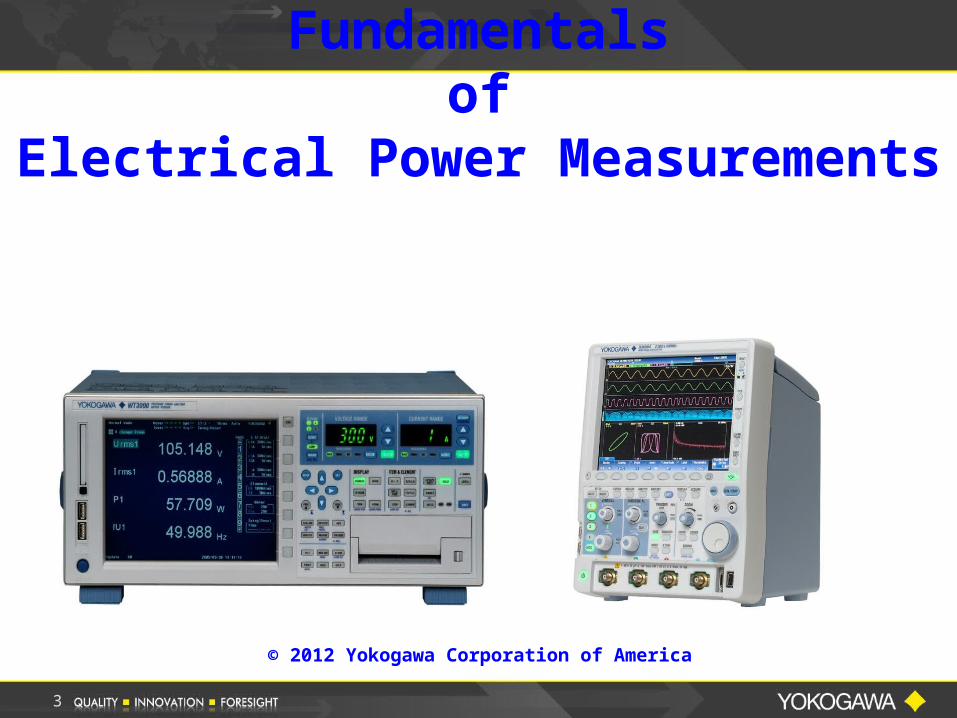
Fundamentalsof
Electrical Power Measurement
© 2012 Yokogawa Corporation of America
Barry BollingApplication EngineerYokogawa Corporation of AmericaCredits: Bill GatheridgePresentation: IEEE / UTC Aerospace
Presenter
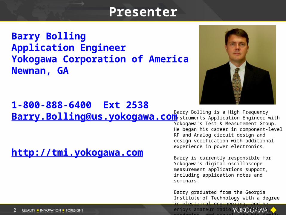
Barry BollingApplication EngineerYokogawa Corporation of AmericaNewnan, GA
1-800-888-6400 Ext [email protected]
http://tmi.yokogawa.com
2
Barry Bolling is a High Frequency Instruments Application Engineer with Yokogawa’s Test & Measurement Group. He began his career in component-level RF and Analog circuit design and design verification with additional experience in power electronics.
Barry is currently responsible for Yokogawa’s digital oscilloscope measurement applications support, including application notes and seminars.
Barry graduated from the Georgia Institute of Technology with a degree in electrical engineering, and he enjoys amateur radio, fly fishing, gardening, and travel with his family.
3
Fundamentalsof
Electrical Power Measurements
© 2012 Yokogawa Corporation of America
4
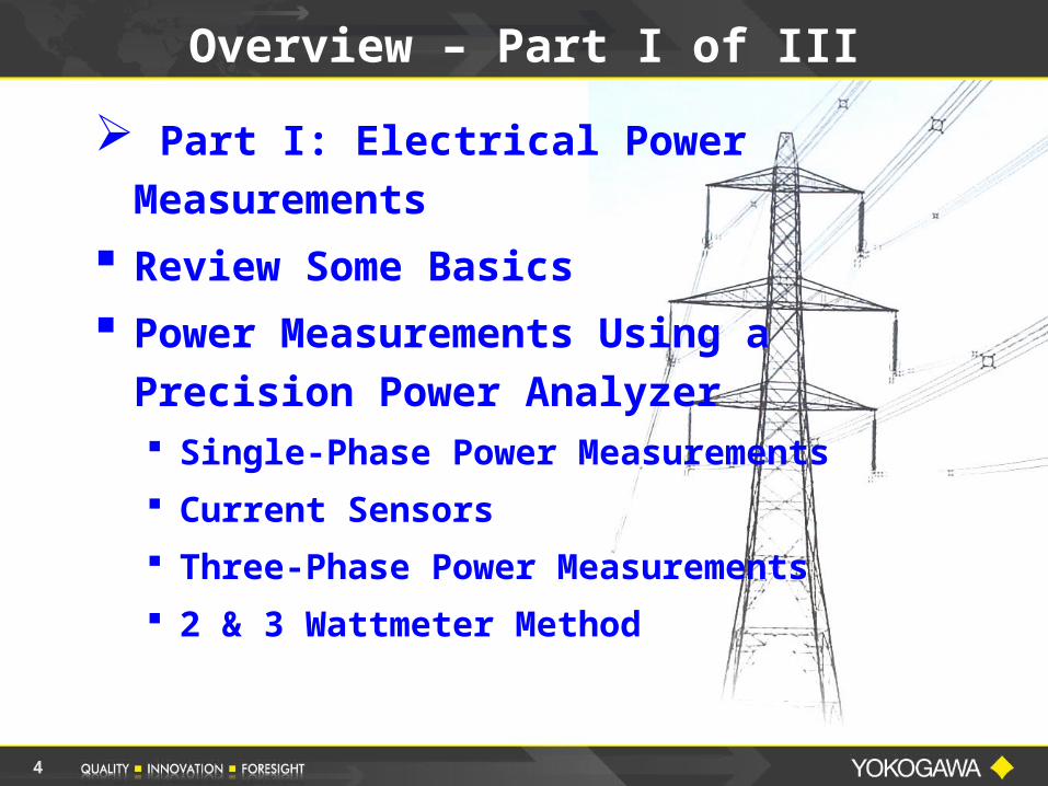
Overview – Part I of III
Part I: Electrical Power Measurements
Review Some Basics
Power Measurements Using a Precision Power Analyzer Single-Phase Power Measurements
Current Sensors
Three-Phase Power Measurements
2 & 3 Wattmeter Method
5
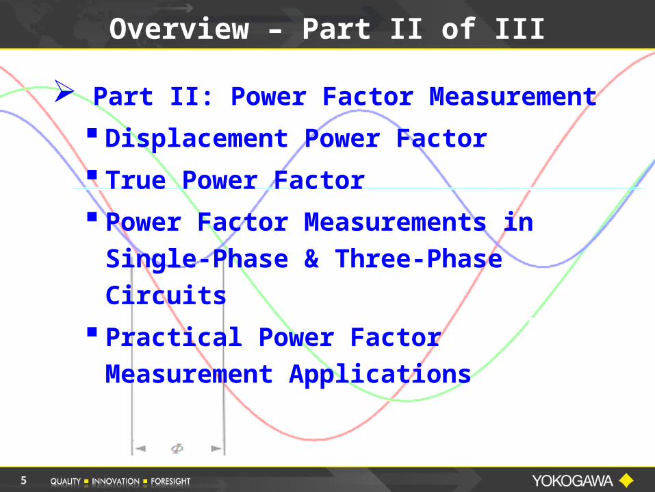
Overview – Part II of III
Part II: Power Factor Measurement
Displacement Power Factor
True Power Factor
Power Factor Measurements in Single-Phase & Three-Phase Circuits
Practical Power Factor Measurement Applications
6
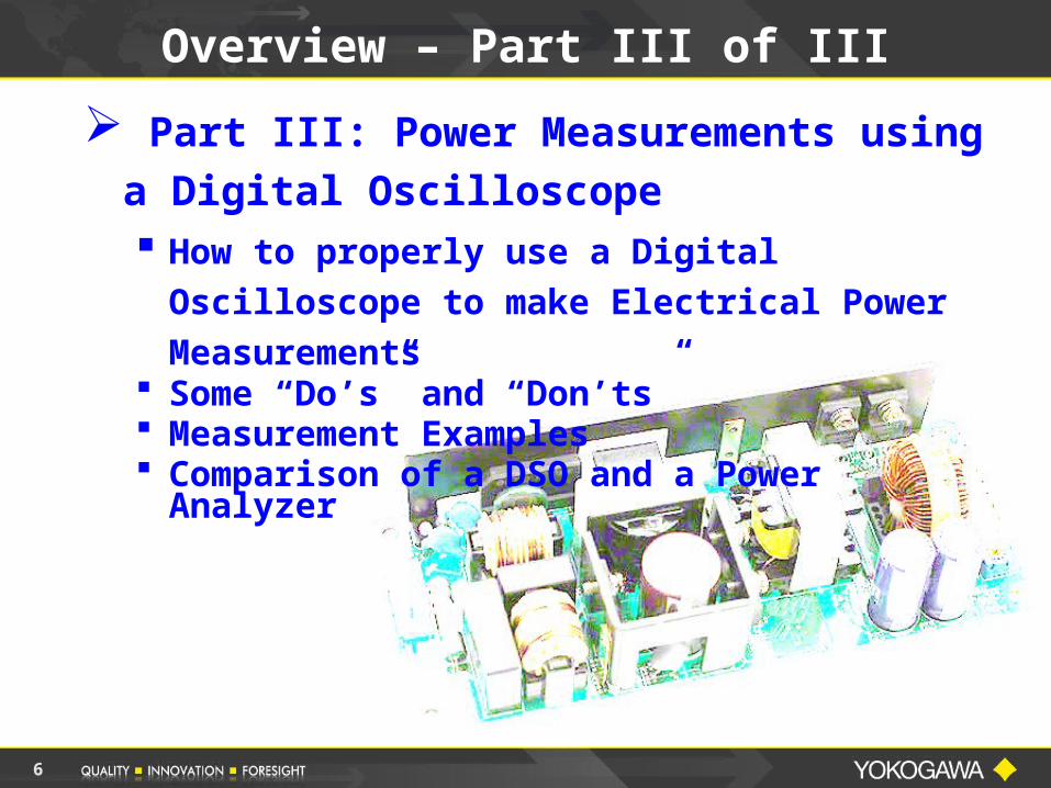
Part III: Power Measurements using a Digital Oscilloscope How to properly use a Digital
Oscilloscope to make Electrical Power Measurements
Some “Do’s” and “Don’ts” Measurement Examples Comparison of a DSO and a Power
Analyzer
Overview – Part III of III
7
Yokogawa Corporate History
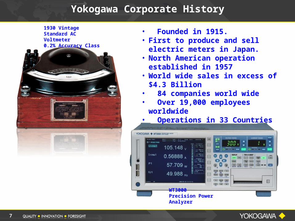
• Founded in 1915.• First to produce and sell electric
meters in Japan.• North American operation
established in 1957• World wide sales in excess of $4.3
Billion• 84 companies world wide• Over 19,000 employees worldwide• Operations in 33 Countries
1930 VintageStandard AC Voltmeter0.2% Accuracy Class
WT3000Precision Power Analyzer

8
Yokogawa Corporation of America Newnan, GA
Yokogawa Corporation of America
9
Part I – Electrical Power Measurements
PART I ELECTRICAL POWER
MEASUREMENTS
10
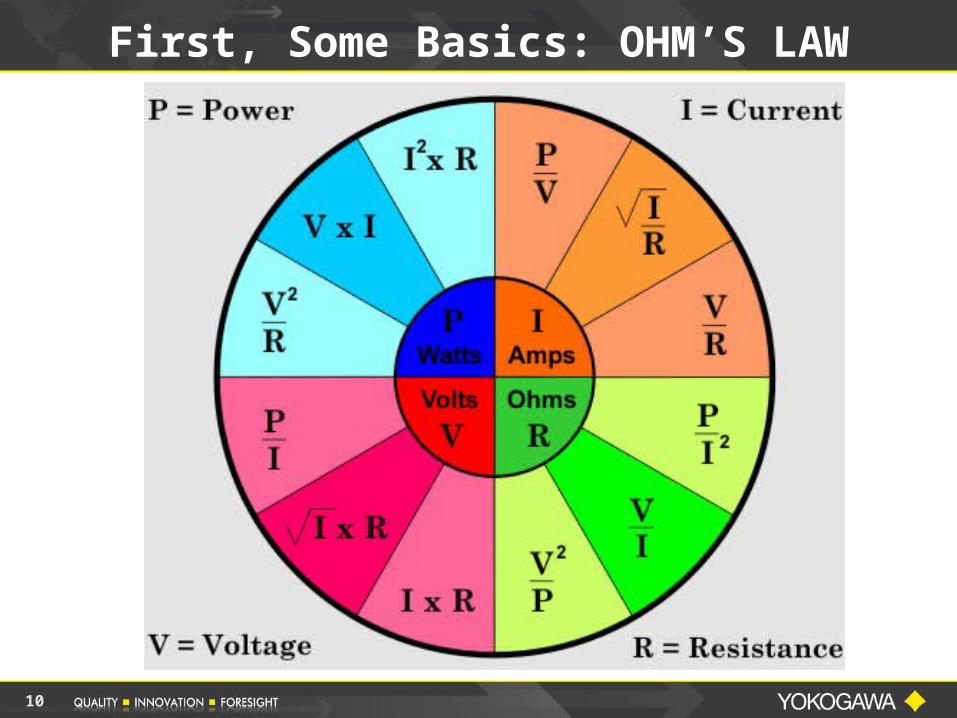
First, Some Basics: OHM’S LAW
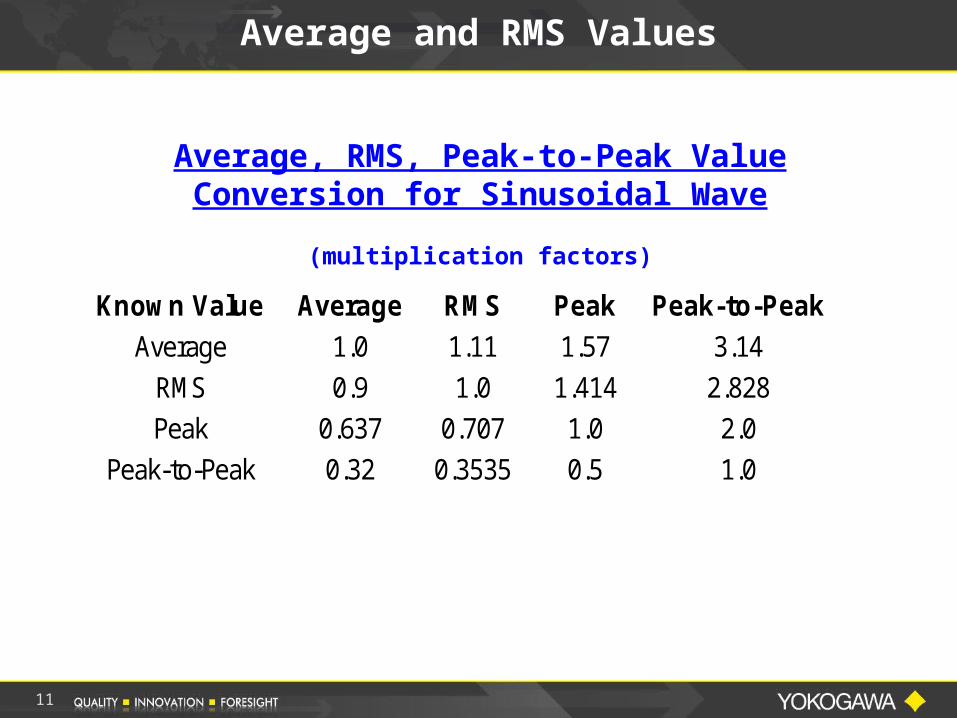
Average and RMS Values
Average, RMS, Peak-to-Peak Value Conversion for Sinusoidal Wave
(multiplication factors)
Known Value Average RMS Peak Peak-to-Peak Average 1.0 1.11 1.57 3.14
RMS 0.9 1.0 1.414 2.828 Peak 0.637 0.707 1.0 2.0
Peak-to-Peak 0.32 0.3535 0.5 1.0
11
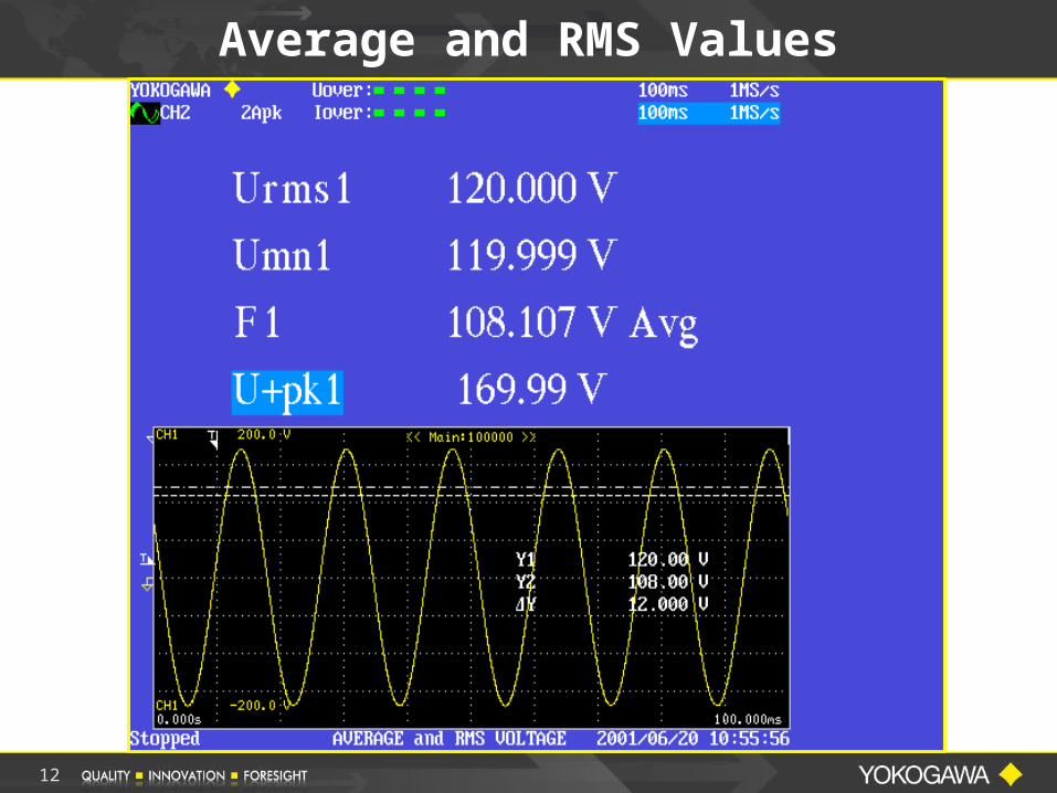
Average and RMS Values
12
13
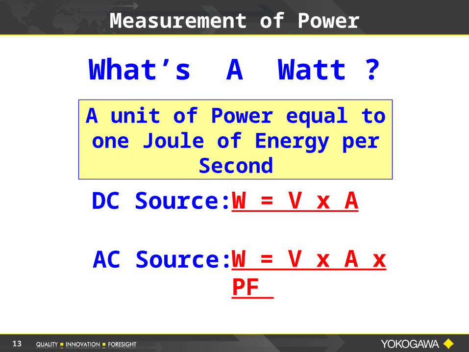
Measurement of Power
What’s A Watt ?
DC Source:
AC Source:
W = V x A
W = V x A x PF
A unit of Power equal to one Joule of Energy per
Second
14
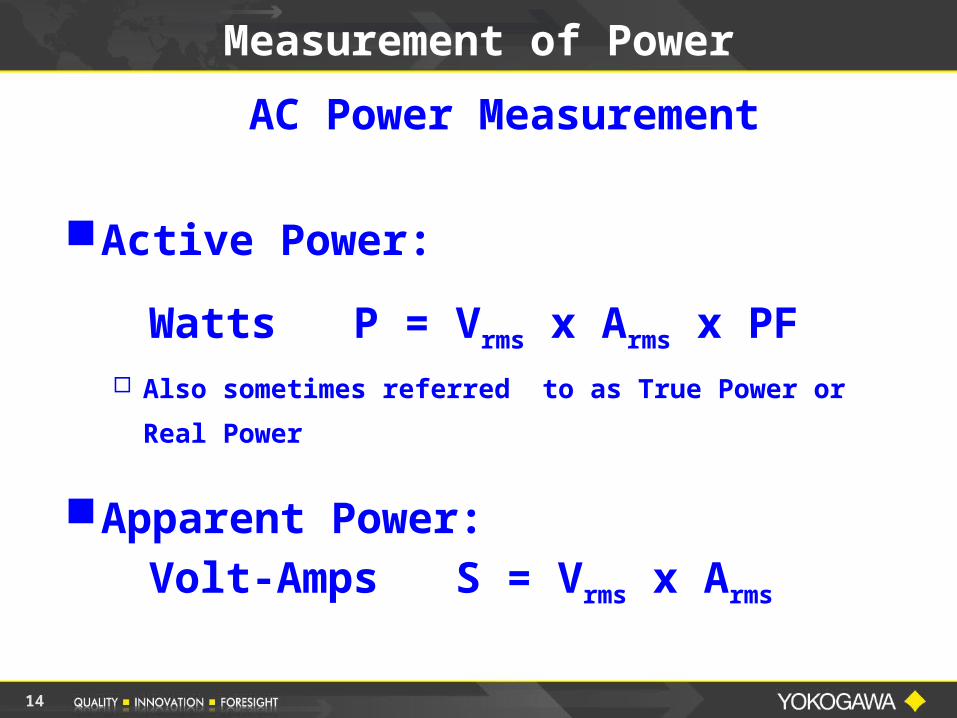
Measurement of Power
AC Power Measurement
Active Power:
Watts P = Vrms x Arms x PF
Also sometimes referred to as True Power or Real
Power
Apparent Power:Volt-Amps S = Vrms x Arms
15
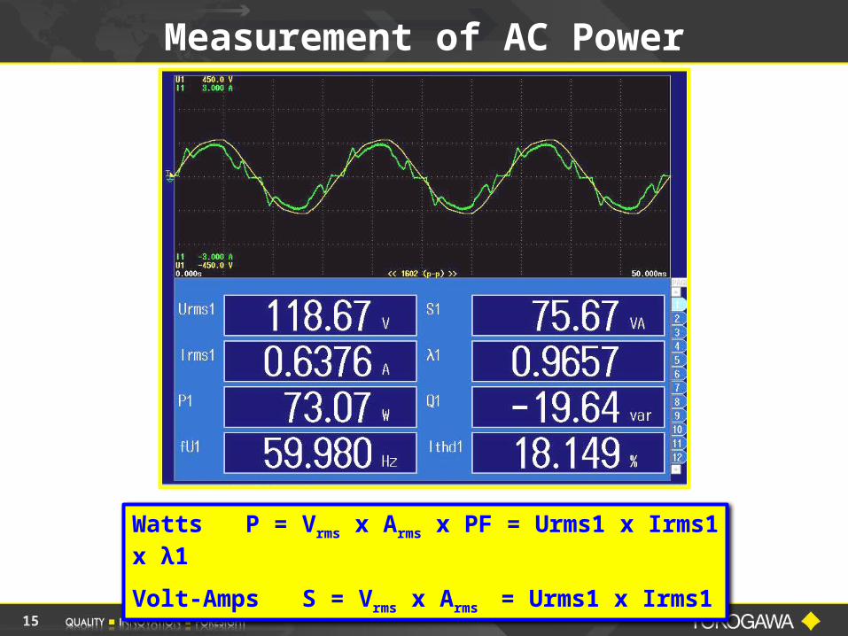
Watts P = Vrms x Arms x PF = Urms1 x Irms1 x λ1
Volt-Amps S = Vrms x Arms = Urms1 x Irms1
Measurement of AC Power
16
Measurement of Power
Digital Power Analyzers are entirely electronic and use some form of DIGITIZING TECHNIQUE to convert analog signals to digital form. higher end analyzers use DIGITAL SIGNAL
PROCESSING techniques to determine values
Digital Power Oscilloscopes use SPECIAL FIRMWARE to make true power measurements
Digitizing instruments are somewhat RESTRICTED because it is a sampled data technique
Many Power Analyzers and Power Scopes apply FFT algorithms for additional power and harmonic analysis
17
Measurement of Power
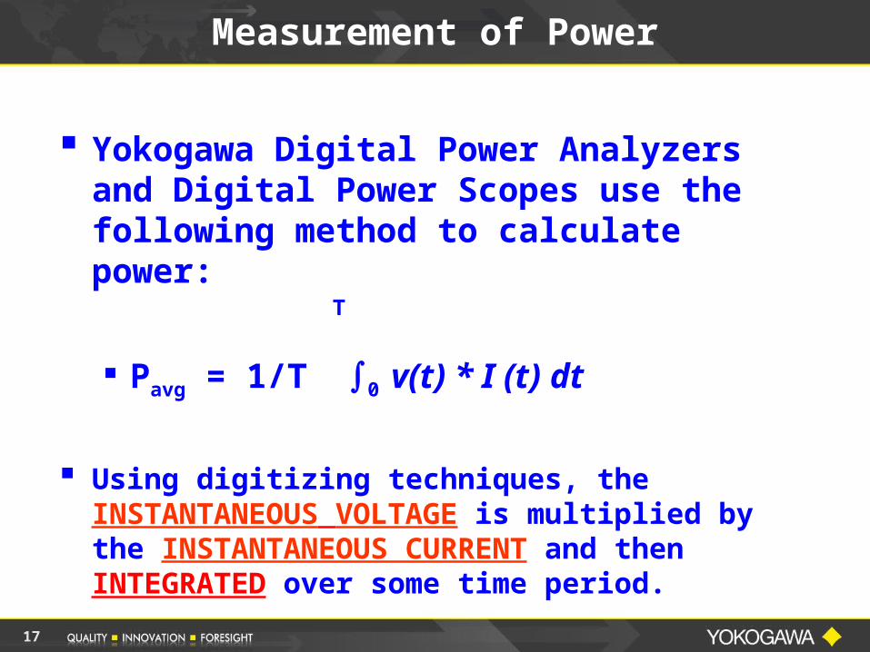
Yokogawa Digital Power Analyzers and Digital Power Scopes use the following method to calculate power:
Pavg = 1/T 0 v(t) * I (t) dt
Using digitizing techniques, the INSTANTANEOUS VOLTAGE is multiplied by the INSTANTANEOUS CURRENT and then INTEGRATED over some time period.
T
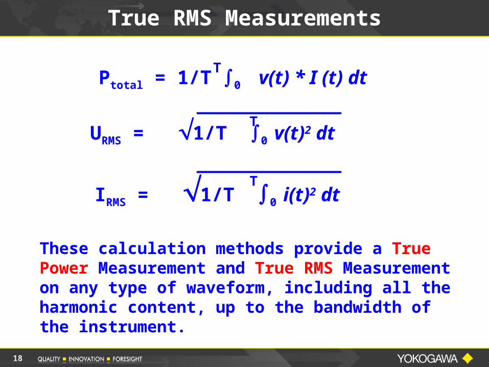
18
These calculation methods provide a True Power Measurement and True RMS Measurement on any type of waveform, including all the harmonic content, up to the bandwidth of the instrument.
T
True RMS Measurements
URMS = 1/T 0 v(t)2 dt
Ptotal = 1/T 0 v(t) * I (t) dt
T
TIRMS = 1/T 0
i(t)2 dt
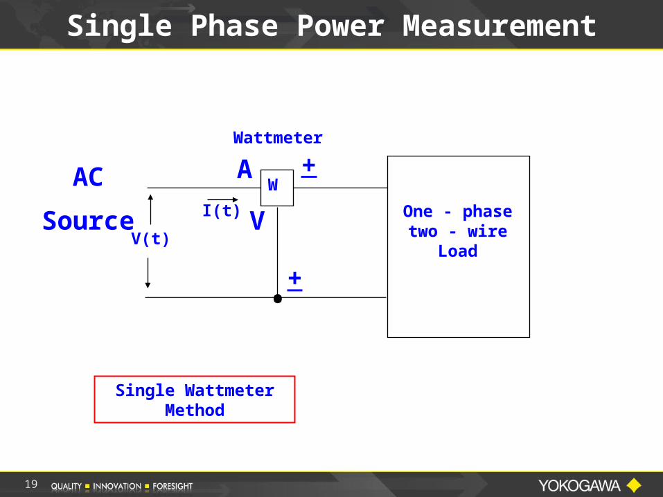
Single Phase Power Measurement
Wattmeter
One - phasetwo - wire
LoadV(t)
I(t)
.
A +
V
+
AC
Source
Single Wattmeter Method
W
19
20
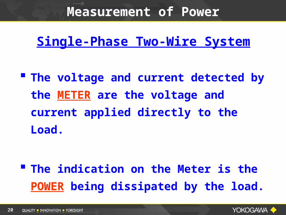
Measurement of Power
Single-Phase Two-Wire System
The voltage and current detected by
the METER are the voltage and
current applied directly to the Load.
The indication on the Meter is the
POWER being dissipated by the load.
21
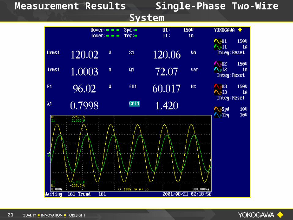
Measurement Results Single-Phase Two-Wire System
22
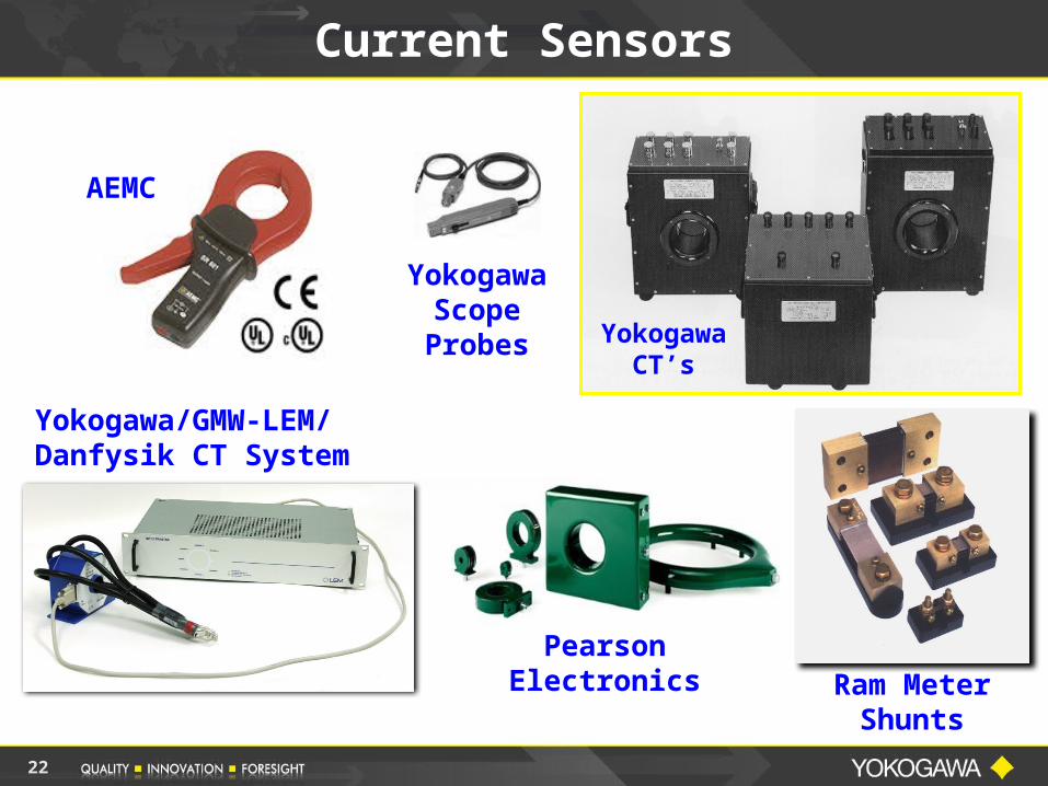
Current Sensors
Ram Meter Shunts
Yokogawa CT’s
AEMC
Yokogawa/GMW-LEM/Danfysik CT System
Yokogawa Scope Probes
Pearson Electronics
23
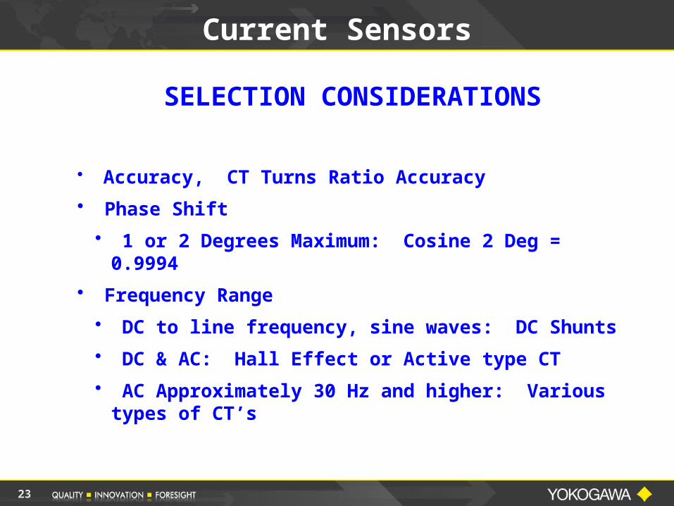
Current Sensors
SELECTION CONSIDERATIONS
• Accuracy, CT Turns Ratio Accuracy
• Phase Shift
• 1 or 2 Degrees Maximum: Cosine 2 Deg = 0.9994
• Frequency Range
• DC to line frequency, sine waves: DC Shunts
• DC & AC: Hall Effect or Active type CT
• AC Approximately 30 Hz and higher: Various types of CT’s
24
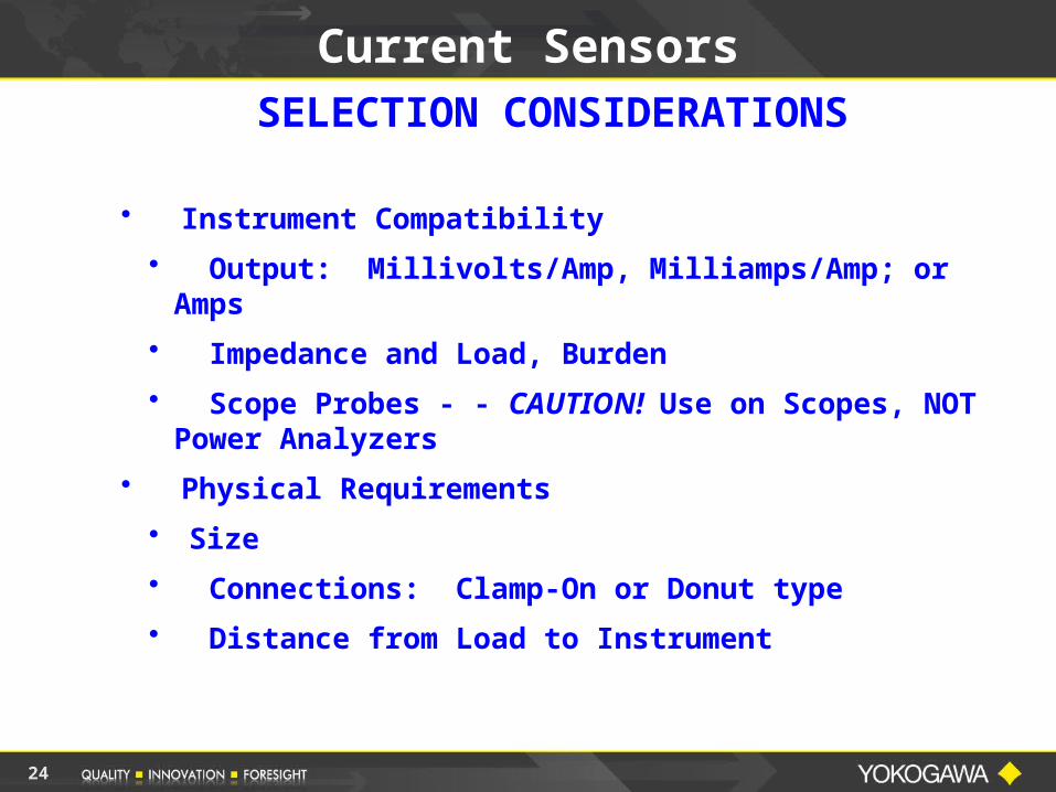
Current SensorsSELECTION CONSIDERATIONS
• Instrument Compatibility
• Output: Millivolts/Amp, Milliamps/Amp; or Amps
• Impedance and Load, Burden
• Scope Probes - - CAUTION! Use on Scopes, NOT Power Analyzers
• Physical Requirements
• Size
• Connections: Clamp-On or Donut type
• Distance from Load to Instrument
25
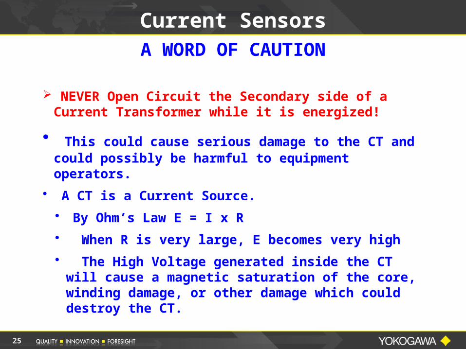
Current SensorsA WORD OF CAUTION
NEVER Open Circuit the Secondary side of a Current Transformer while it is energized!
• This could cause serious damage to the CT and could possibly be harmful to equipment operators.
• A CT is a Current Source.
• By Ohm’s Law E = I x R
• When R is very large, E becomes very high
• The High Voltage generated inside the CT will cause a magnetic saturation of the core, winding damage, or other damage which could destroy the CT.
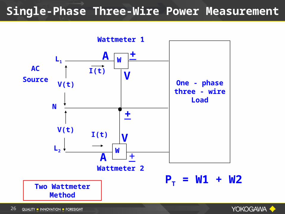
Single-Phase Three-Wire Power Measurement
One - phasethree - wire
Load
Wattmeter 1
V(t)
I(t)
V(t)
I(t)
Wattmeter 2
N .
PT = W1 + W2
A
+
AC
Source
A
+
+
V
V
Two Wattmeter Method
L1
L2
W
W
26
27
Measurement of Power
Single-Phase Three-Wire System(Split Phase)
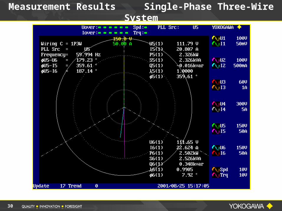
The voltage and current detected by the METERS are the voltage and current applied directly to the Load.
The indication on EACH METER is the power being delivered by the LINE to which the meter is connected.
The total power dissipated by the load is the ALGEBRAIC SUM of the two indications.
28
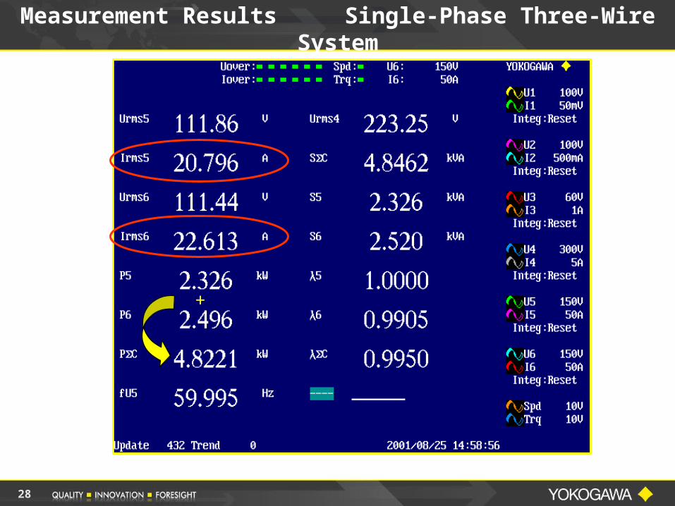
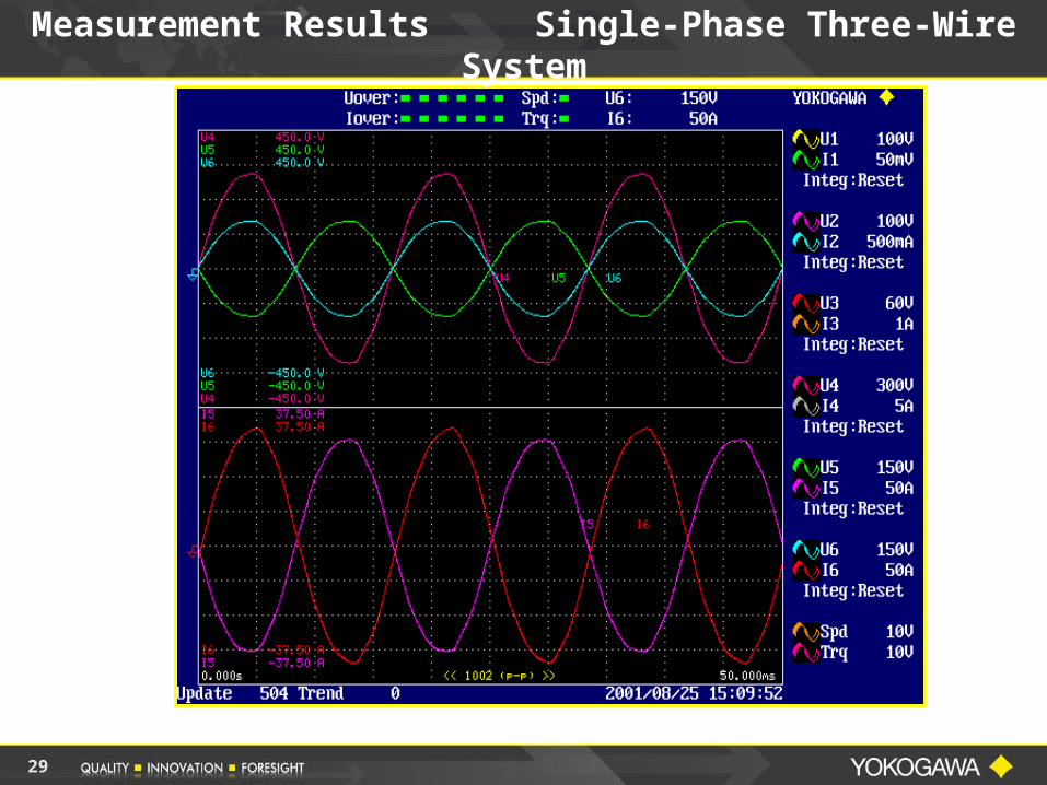
Measurement Results Single-Phase Three-Wire System
+
29
Measurement Results Single-Phase Three-Wire System
30
Measurement Results Single-Phase Three-Wire System
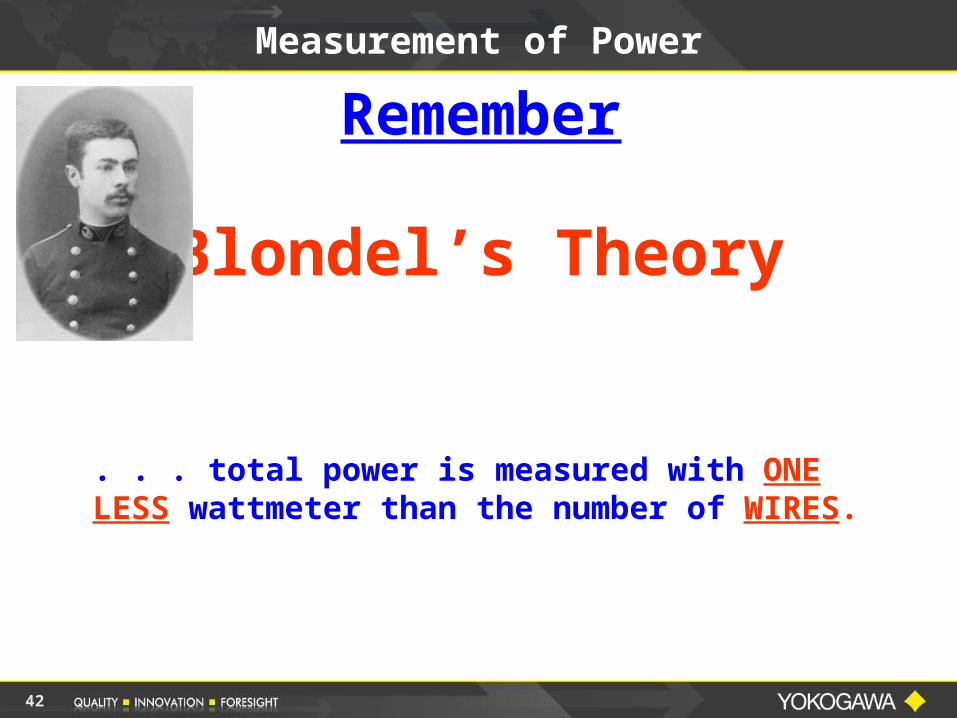
Measurement of Power
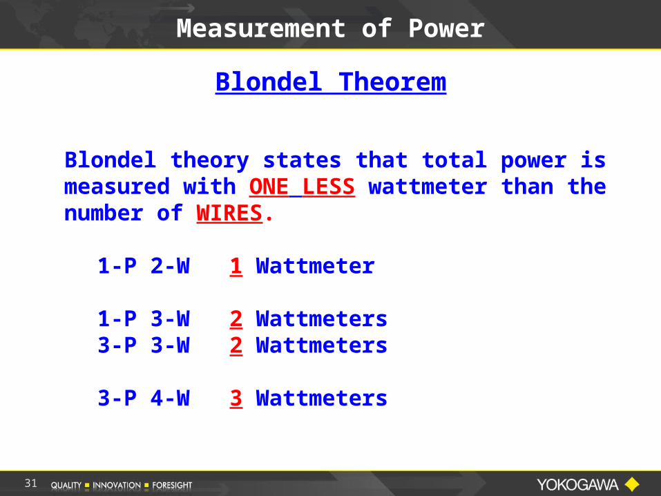
Blondel theory states that total power is measured with ONE LESS wattmeter than the number of WIRES.
1-P 2-W 1 Wattmeter
1-P 3-W 2 Wattmeters3-P 3-W 2 Wattmeters
3-P 4-W 3 Wattmeters
Blondel Theorem
31

Andre Blondel
32
Blondel was born in France. He was employed as an engineer by the Lighthouses and Beacons Service until he retired in 1927 as its general first class inspector.He became a professor of electrotechnology at the School of Bridges and Highways and the School of Mines. Very early in his career he suffered immobility due to a paralysis of his legs, which confined him to his room for 27 years, but he never stopped working.
In 1893 André Blondel sought to solved the problem of integral synchronization. He determined the conditions under which the curve traced by a high-speed recording instrument would follow as closely as possible the actual variations of the physical phenomenon being studied.
This led him to invent the bifilar and soft iron oscillographs. These instruments won the grand prize at the St. Louis Exposition in 1904. They remained the best way to record high-speed electrical phenomena for more than 40 years when they were replaced by the cathode ray oscilloscope.
He published Empirical Theory of Synchronous Generators which contained the basic theory of the two armature reactions (direct and transverse). It was used extensively to explain the properties of salient-pole AC machines.
In 1909, assisted by M. Mähl, he worked on one of the first long distance schemes for the transmission of AC power. The project created a (then) large 300,000 hp hydroelectric power plant at Genissiat on the River Rhone, and transmitted electrical power to Paris more than 350 km away using polyphase AC current at 120 kV.
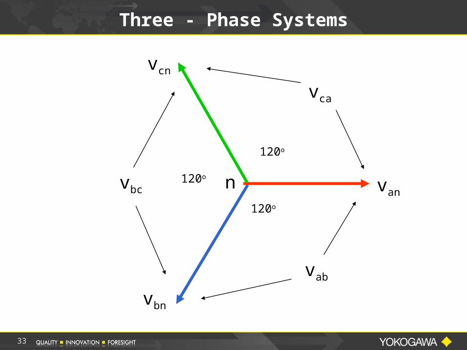
Three - Phase Systems
van
vbn
vcn
120o
120o
120o n
vab
vbc
vca
33
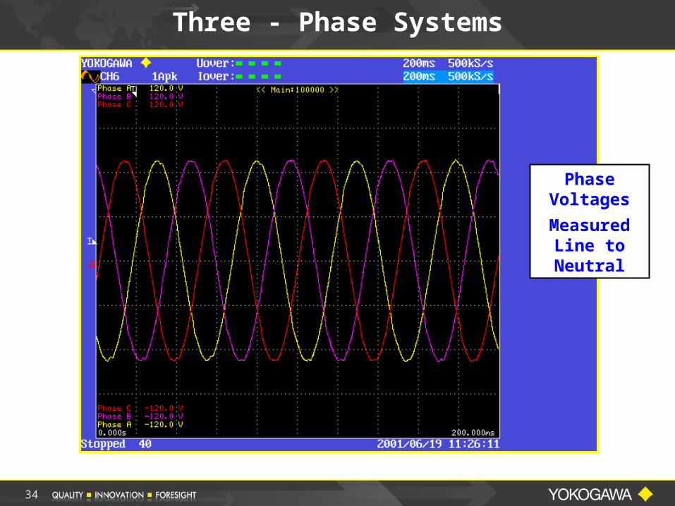
Phase Voltages
Measured Line to Neutral
Three - Phase Systems
34
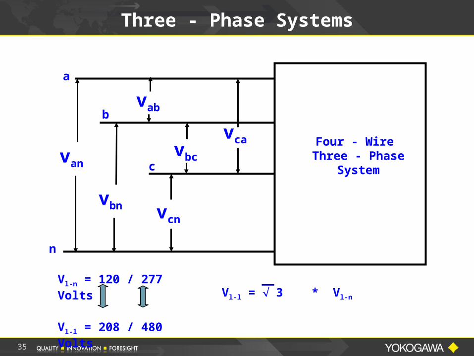
Three - Phase Systems
a
b
c
n
van
vbn vcn
vab
vbc
vca Four - Wire Three - Phase
System
Vl-n = 120 / 277 Volts
Vl-l = 208 / 480 Volts
Vl-l = 3 * Vl-n
35
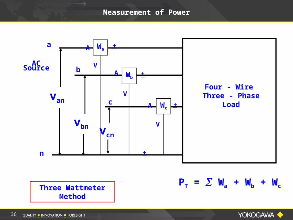
Measurement of Power
a
b
c
n
van
vbn vcn
Four - Wire Three - Phase
Load
Wa
Wb
Wc
PT = Wa + Wb + Wc
ACSource
A
A
+
A
Three Wattmeter Method
+
+
+
V
V
V
36
37
Measurement of Power
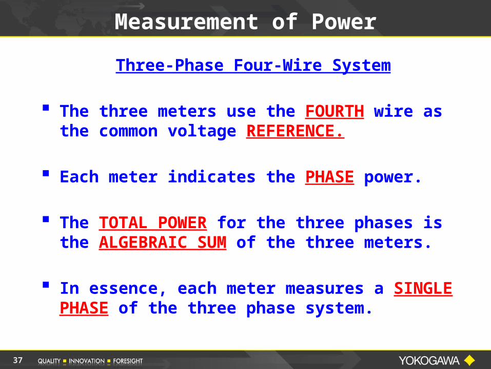
Three-Phase Four-Wire System
The three meters use the FOURTH wire as the common voltage REFERENCE.
Each meter indicates the PHASE power.
The TOTAL POWER for the three phases is the ALGEBRAIC SUM of the three meters.
In essence, each meter measures a SINGLE PHASE of the three phase system.
38
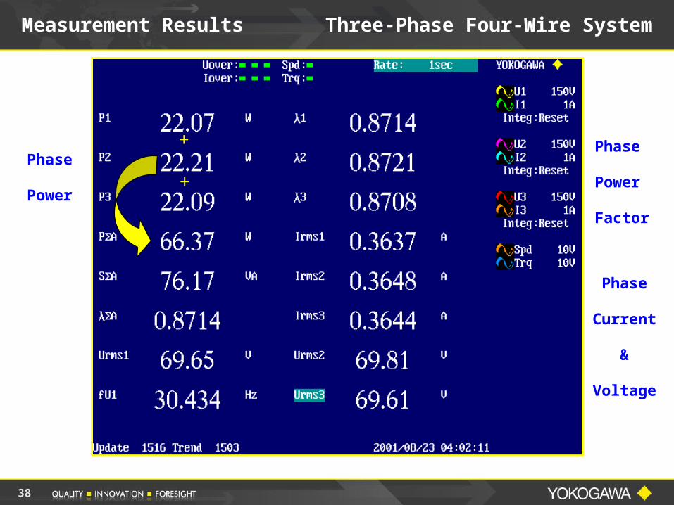
Measurement Results Three-Phase Four-Wire System
Phase
Power
Phase
Power
Factor
Phase
Current
&
Voltage
+
+
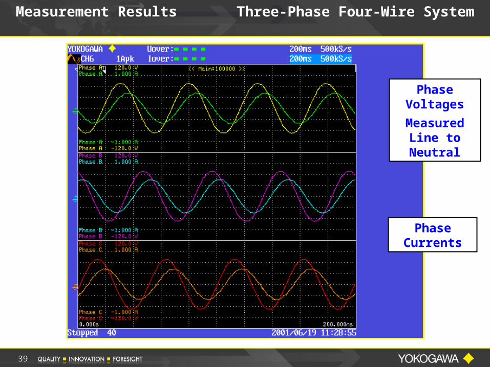
Phase Voltages
Measured Line to Neutral
Phase Currents
Measurement Results Three-Phase Four-Wire System
39
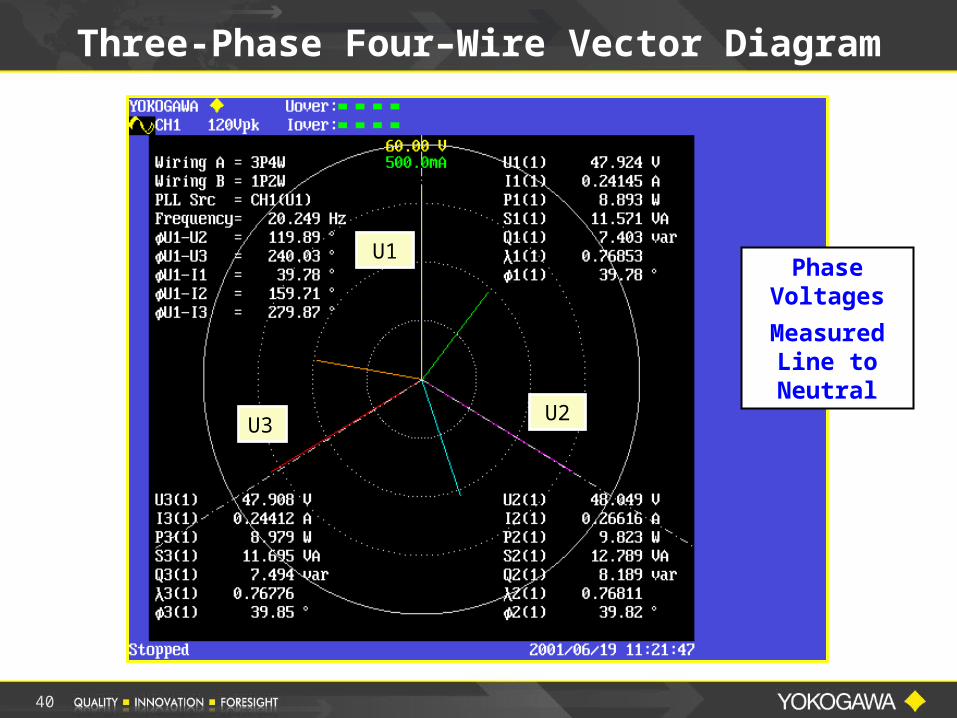
Three-Phase Four–Wire Vector Diagram
U1
U2U3
Phase Voltages
Measured Line to Neutral
40
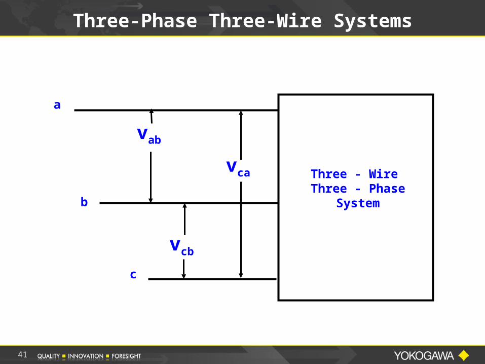
Three-Phase Three-Wire Systems
a
b
c
vab
vcb
vca Three - Wire Three - Phase
System
41
42
Measurement of Power
Remember
Blondel’s Theory
. . . total power is measured with ONE LESS wattmeter than the number of WIRES.
43
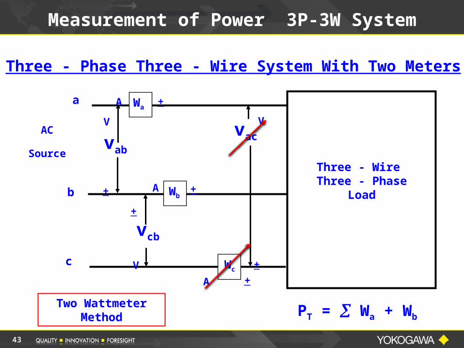
Measurement of Power 3P-3W System
AC
Source
a
b
c
vac
vcb
vab
Three - Wire Three - Phase
Load
Wa
Wb
Wc
A
A
A
V
V
+
V
+
+
+
+
+
Two Wattmeter Method
Three - Phase Three - Wire System With Two Meters
PT = Wa + Wb
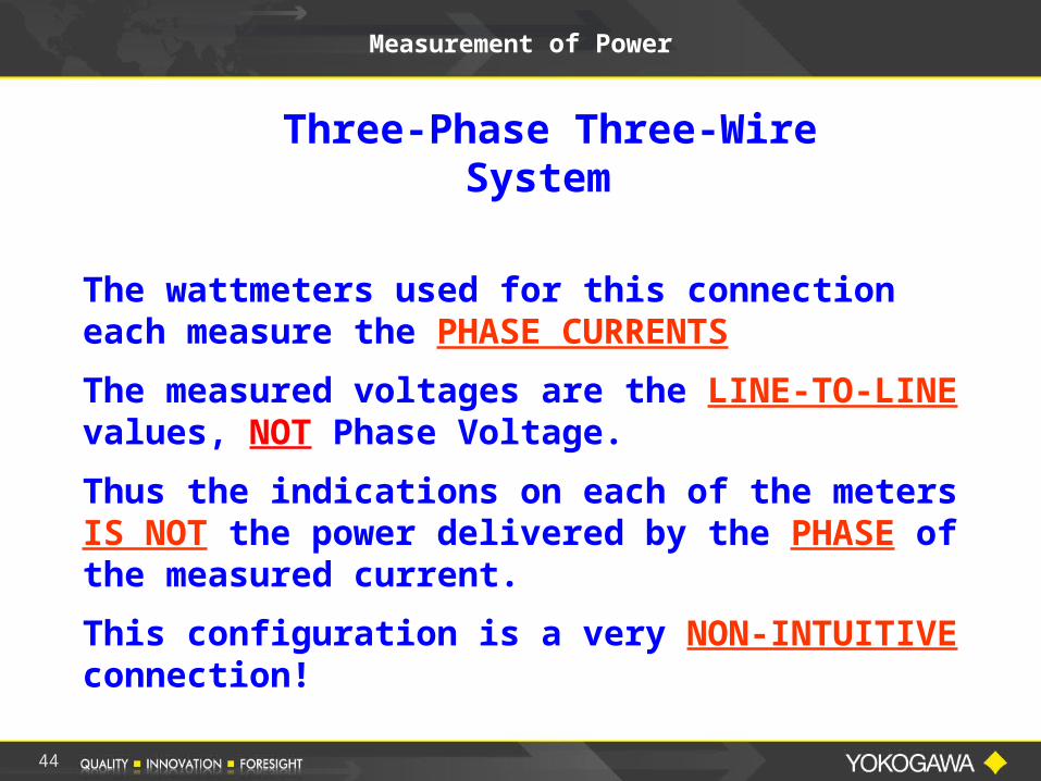
Measurement of Power
Three-Phase Three-Wire System
The wattmeters used for this connection each measure the PHASE CURRENTS
The measured voltages are the LINE-TO-LINE values, NOT Phase Voltage.
Thus the indications on each of the meters IS NOT the power delivered by the PHASE of the measured current.
This configuration is a very NON-INTUITIVE connection!
44
45
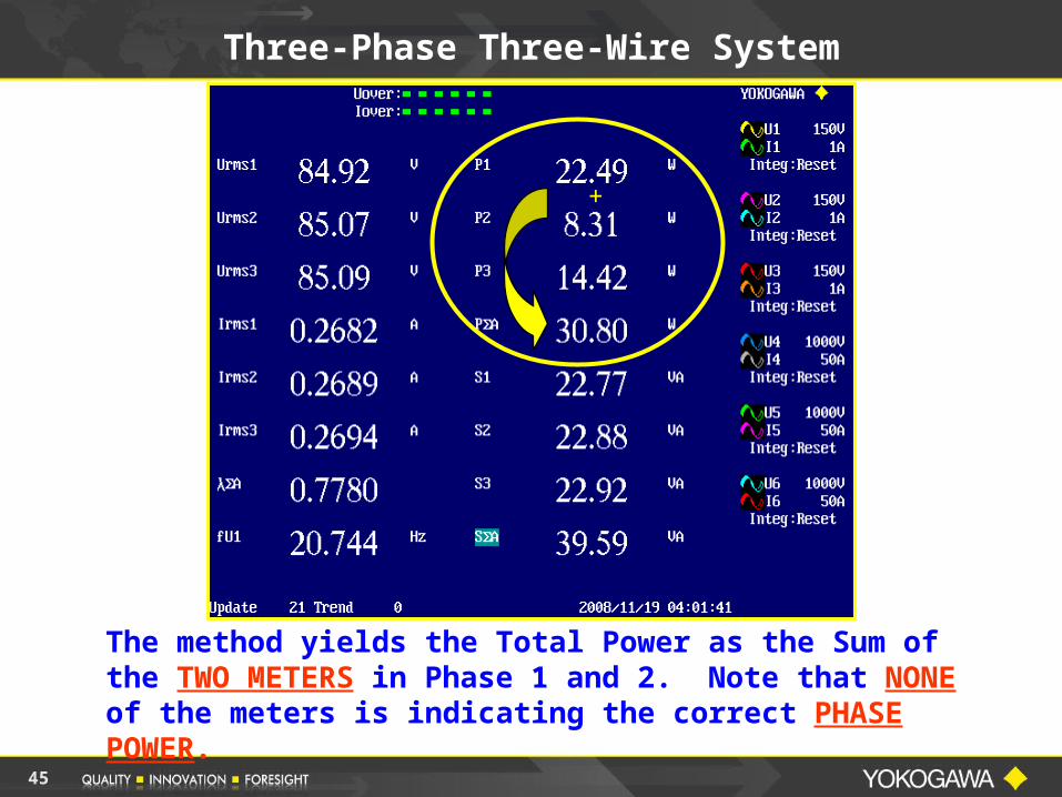
Three-Phase Three-Wire System
The method yields the Total Power as the Sum of the TWO METERS in Phase 1 and 2. Note that NONE of the meters is indicating the correct PHASE POWER.
+
The Two Wattmeter technique tends to cause less confusion than the three meter technique since there is no expectation that a meter will give an accurate phase indication.
However, with the Yokogawa Power Analyzers, on a 3-Phase 3-Wire System, use the 3V-3A wiring method. This method will give all three Voltages and Currents, and correct Total Power, Total Power Factor and VA Measurements on either Balanced or Unbalanced 3-Wire system.
Electrical Power Measurements
46
47
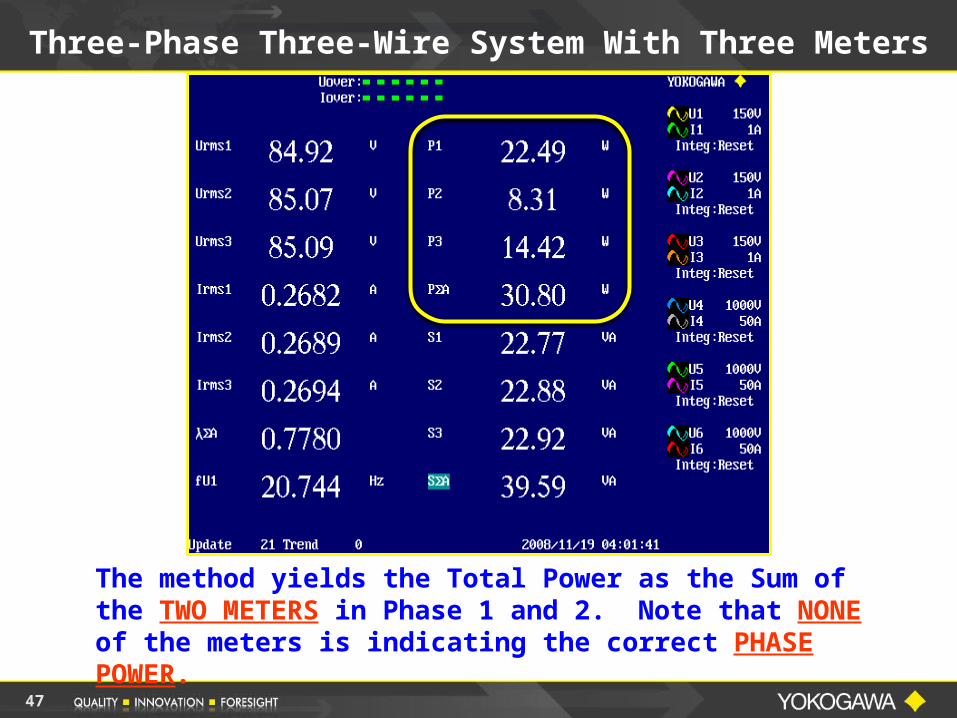
Three-Phase Three-Wire System With Three Meters
The method yields the Total Power as the Sum of the TWO METERS in Phase 1 and 2. Note that NONE of the meters is indicating the correct PHASE POWER.
48
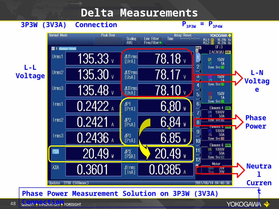
Delta MeasurementsP3P3W = P3P4W
L-NVoltag
e
Phase Power
L-LVoltage
+
+
3P3W (3V3A) Connection
Neutral
CurrentPhase Power Measurement Solution on 3P3W (3V3A)
Connection 48
49
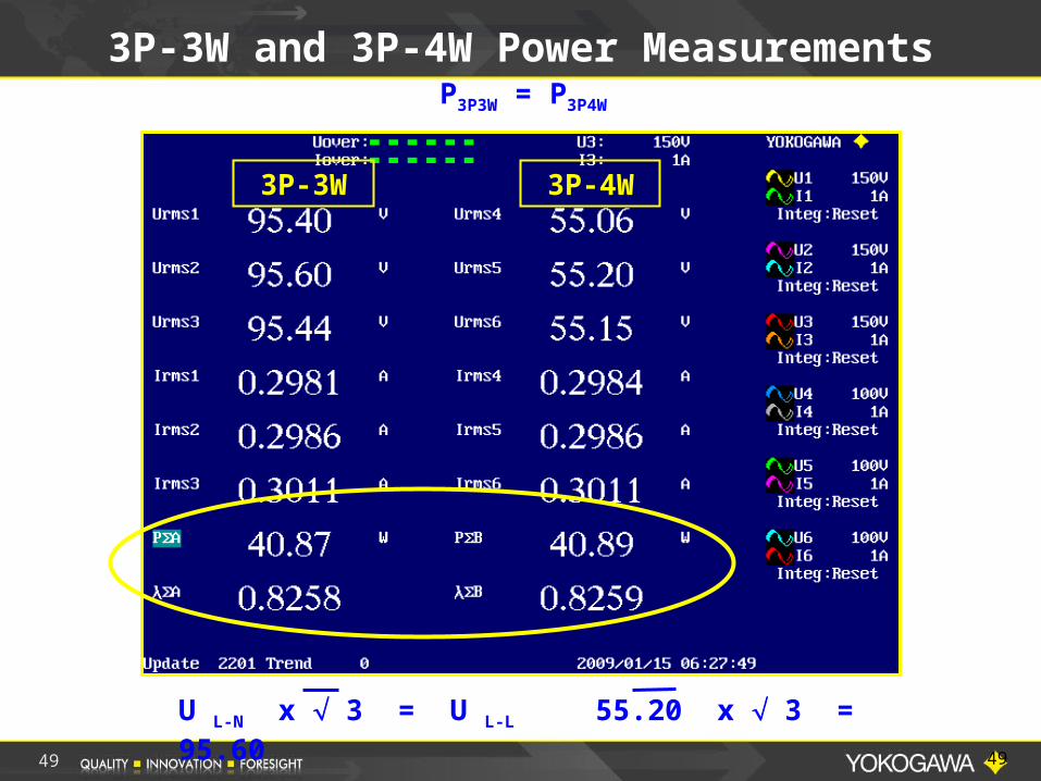
3P-3W and 3P-4W Power Measurements
U L-N x 3 = U L-L 55.20 x 3 = 95.60
P3P3W = P3P4W
3P-3W 3P-4W
49
50
Part II - Power Factor Measurements
PART II POWER FACTOR MEASUREMENTS
51
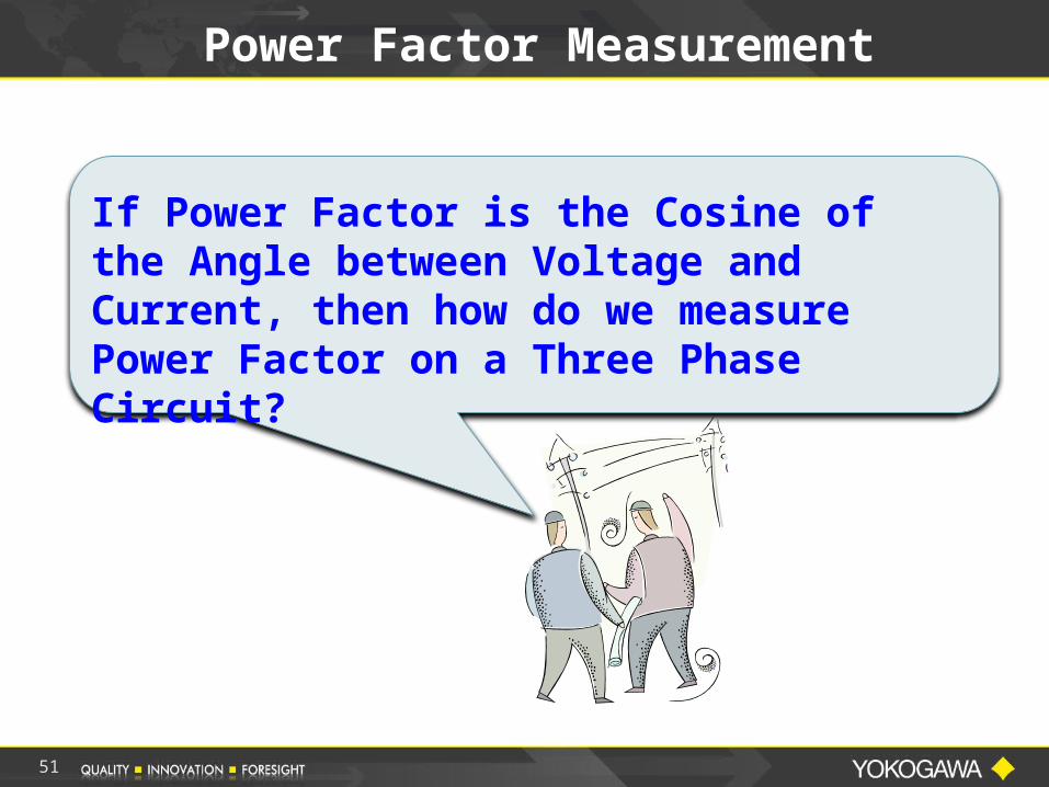
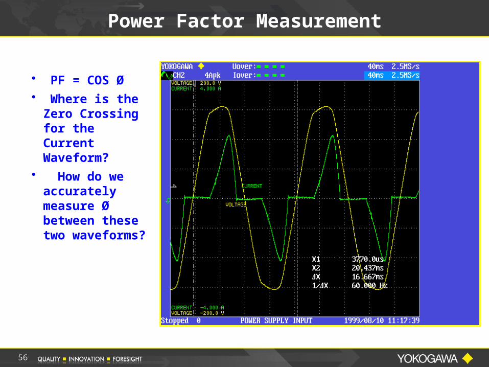
Power Factor Measurement
If Power Factor is the Cosine of the Angle between Voltage and Current, then how do we measure Power Factor on a Three Phase Circuit?
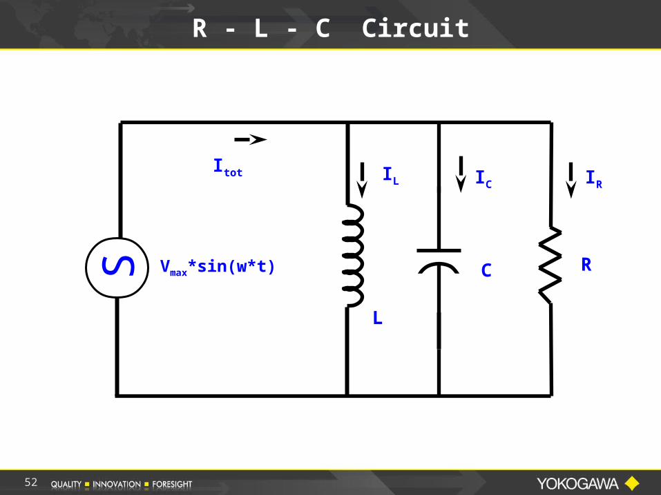
R - L - C Circuit
Vmax*sin(w*t)
Itot IC IR
RC
IL
L
S
52
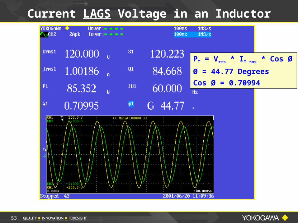
Current LAGS Voltage in an Inductor
PT = Vrms * IT rms * Cos Ø
Ø = 44.77 Degrees
Cos Ø = 0.70994
53
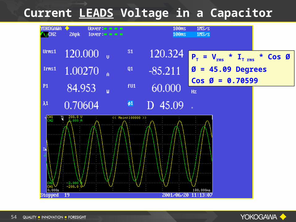
Current LEADS Voltage in a Capacitor
PT = Vrms * IT rms * Cos Ø
Ø = 45.09 Degrees
Cos Ø = 0.70599
54
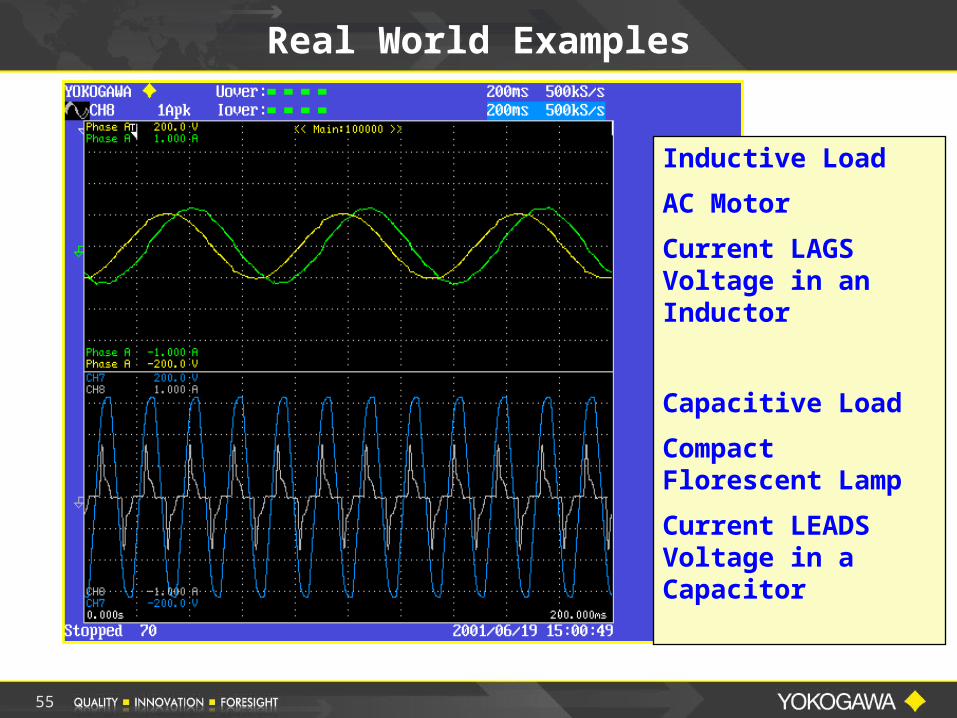
Inductive Load
AC Motor
Current LAGS Voltage in an Inductor
Capacitive Load
Compact Florescent Lamp
Current LEADS Voltage in a Capacitor
Real World Examples
55
Power Factor Measurement
• PF = COS Ø • Where is the
Zero Crossing for the Current Waveform?
• How do we accurately measure Ø between these two waveforms?
56
Power Factor Measurement
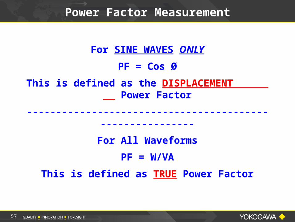
For SINE WAVES ONLY
PF = Cos Ø
This is defined as the DISPLACEMENT Power Factor
---------------------------------------------------------
For All Waveforms
PF = W/VA
This is defined as TRUE Power Factor
57
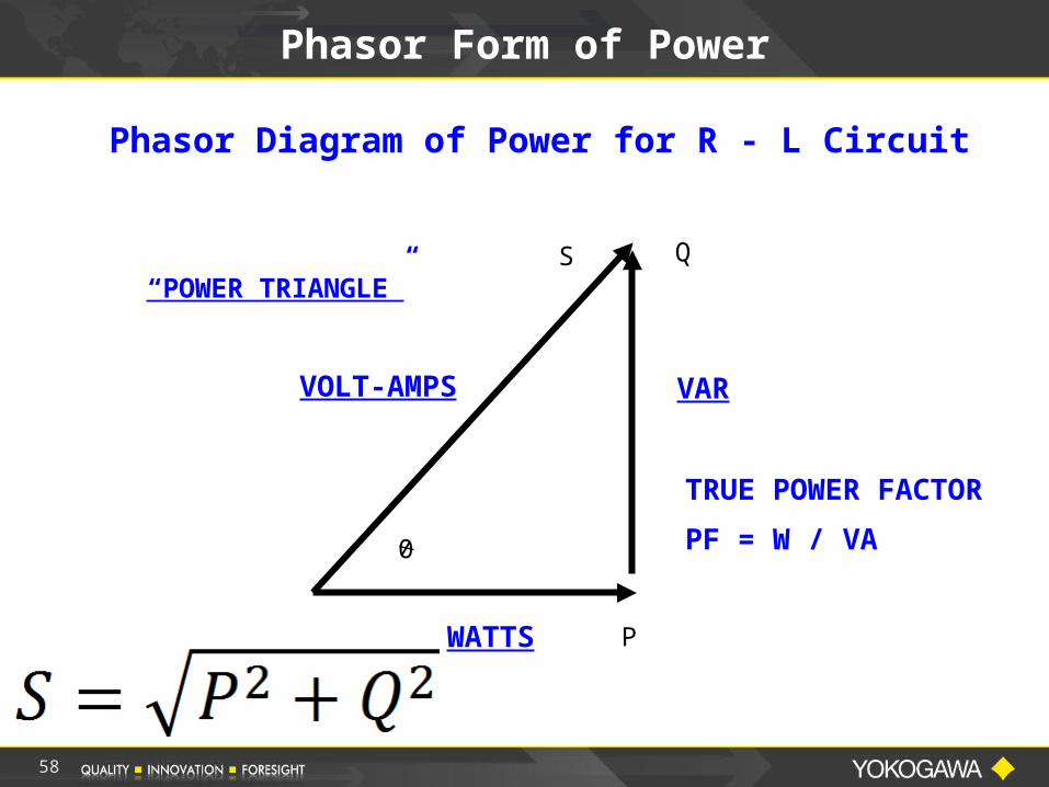
Phasor Form of Power
P
QS
0
Phasor Diagram of Power for R - L Circuit
VAR
WATTS
VOLT-AMPS
TRUE POWER FACTOR
PF = W / VA
“POWER TRIANGLE”
58
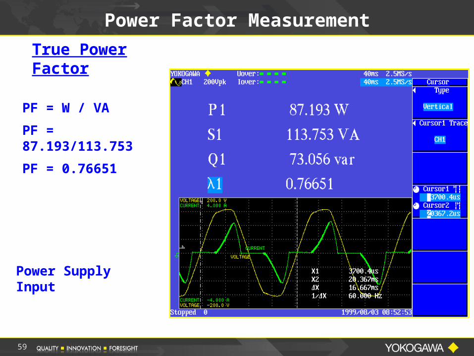
Power Factor Measurement
True Power Factor
PF = W / VA
PF = 87.193/113.753
PF = 0.76651
Power Supply Input
59
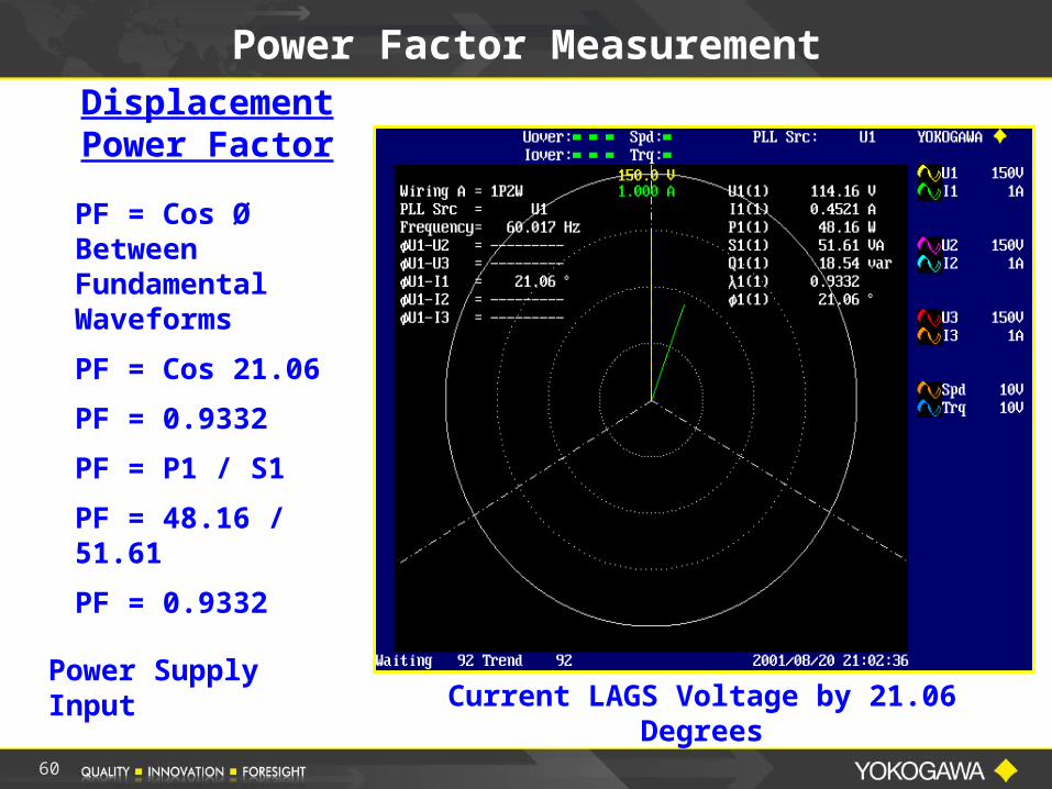
Power Factor MeasurementDisplacement Power Factor
Power Supply Input
PF = Cos Ø Between Fundamental Waveforms
PF = Cos 21.06
PF = 0.9332
PF = P1 / S1
PF = 48.16 / 51.61
PF = 0.9332
Current LAGS Voltage by 21.06 Degrees
60
Power Factor on 3-Phase System
3-Phase 4-Wire System
PFTotal = W / VA
PFTotal = ( W1 + W2 + W3 ) / ( VA1 + VA2 + VA3 )
61
Power Factor on 3-Phase 3-Wire System
Using 2 Wattmeter Method
PFTotal = W / VA
PFTotal = ( W1 + W2 ) / ( 3/2)( VA1 + VA2 )
• If the load is Unbalanced, that is the Phase Currents are different, this method could result in an error in calculating total Power Factor since only two VA measurements are used in the calculation.
62
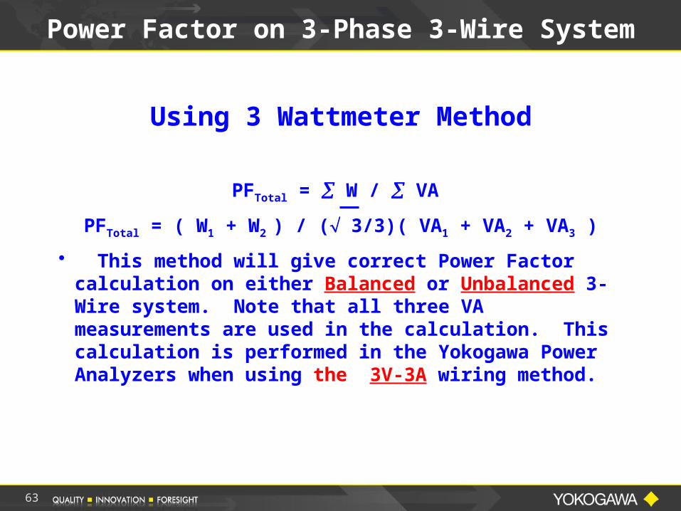
Power Factor on 3-Phase 3-Wire System
Using 3 Wattmeter Method
PFTotal = W / VA
PFTotal = ( W1 + W2 ) / ( 3/3)( VA1 + VA2 + VA3 )
• This method will give correct Power Factor calculation on either Balanced or Unbalanced 3-Wire system. Note that all three VA measurements are used in the calculation. This calculation is performed in the Yokogawa Power Analyzers when using the 3V-3A wiring method.
63
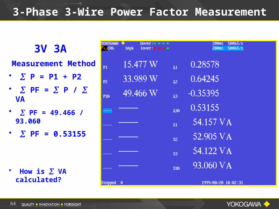
3-Phase 3-Wire Power Factor Measurement
3V 3A Measurement
Method
• P = P1 + P2
• PF = P / VA
• PF = 49.466 / 93.060
• PF = 0.53155
• How is VA calculated?
64
65
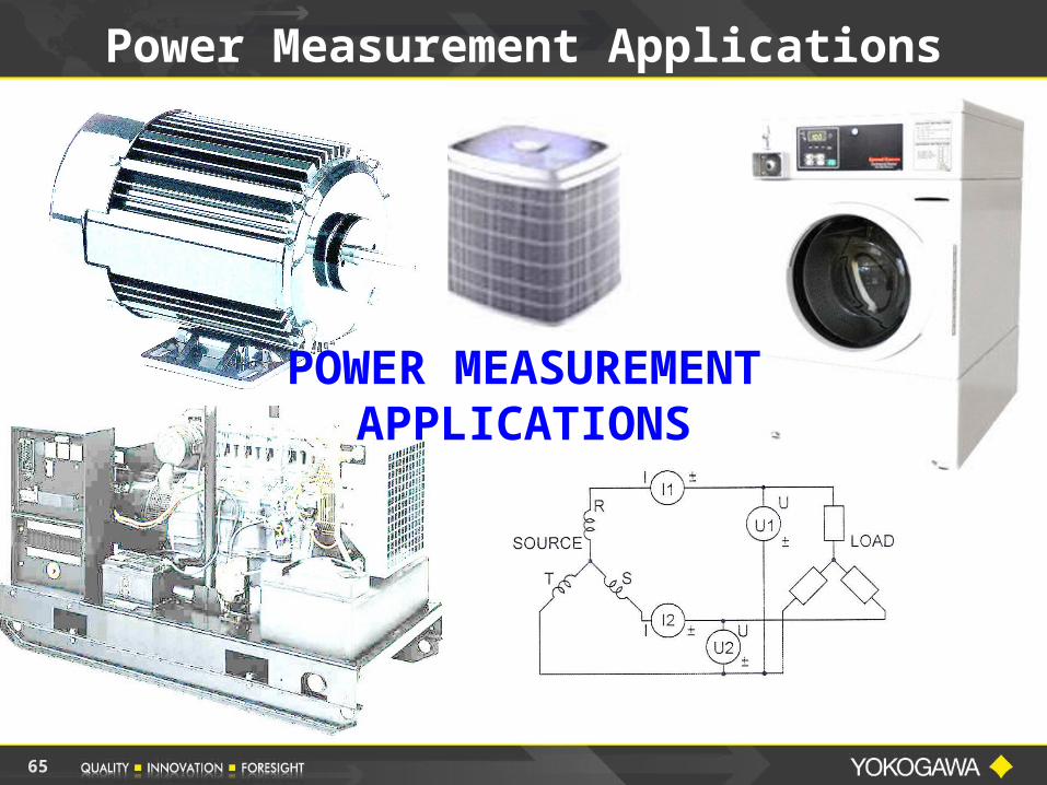
Power Measurement Applications
POWER MEASUREMENT APPLICATIONS
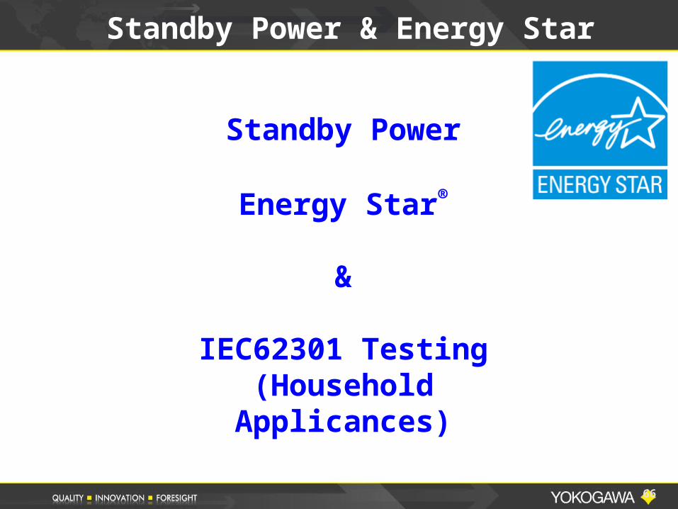
Standby Power
Energy Star®
&
IEC62301 Testing(Household
Applicances)
66
Standby Power & Energy Star
International Standard IEC62301
Household Electrical Appliances –
Measurement of Standby Power
Hardware and Software Measurement Solution
Overview
67
Scope of IEC62301
IEC62301 specifies methods of measurement of electrical power consumption in Standby Mode.
IEC62301 is applicable to mains-powered electrical household appliances.
The objective of this standard is to provide a standard method of test to determine the power consumption of a range of appliances and equipment in standby mode.
68
Terms and Definitions
The Standard also references Twenty Five (25) IEC Standards for various Household electrical appliances.
These standards define the various test parameters with the limits for items such as THD, Power and other items for the appropriate product.
In the US and North America, the Energy Star® standard is typically used for the testing limits.
69
70
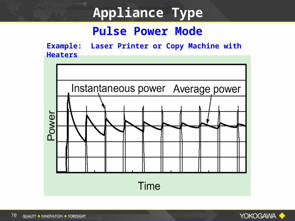
Appliance TypePulse Power Mode
Example: Laser Printer or Copy Machine with Heaters
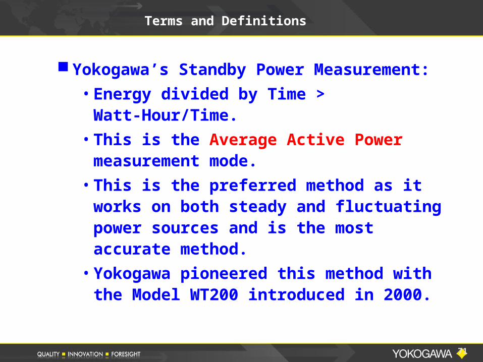
Terms and Definitions
Yokogawa’s Standby Power Measurement:
• Energy divided by Time > Watt-Hour/Time.
• This is the Average Active Power measurement mode.
• This is the preferred method as it works on both steady and fluctuating power sources and is the most accurate method.
• Yokogawa pioneered this method with the Model WT200 introduced in 2000.
71
72
Other Applications
OTHER APPLICATIONS
73
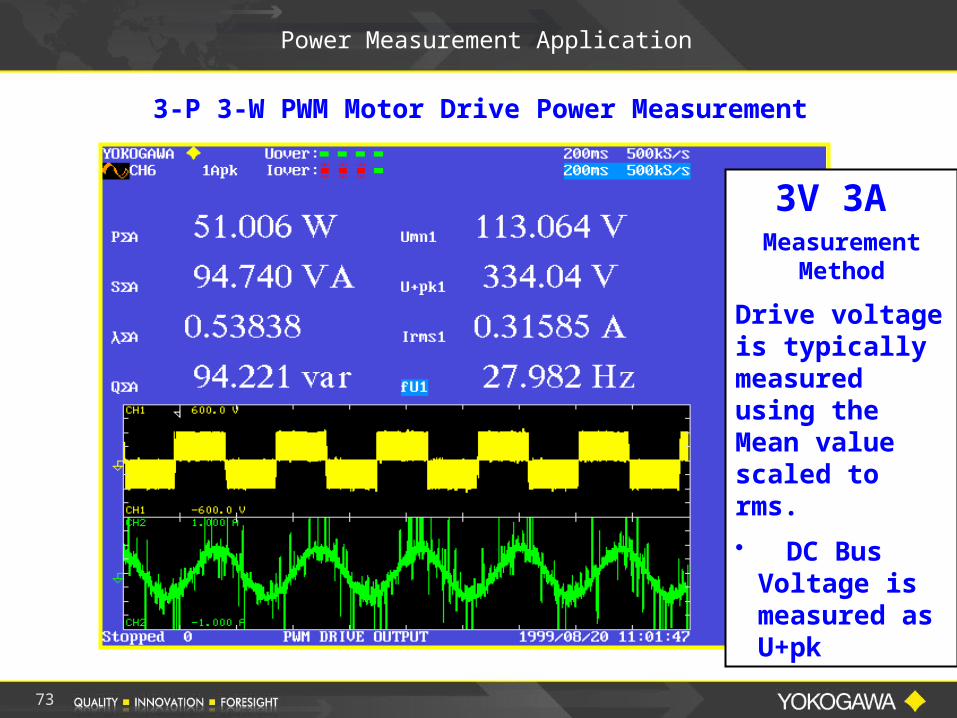
Power Measurement Application
3-P 3-W PWM Motor Drive Power Measurement
3V 3A Measurement
Method
Drive voltage is typically measured using the Mean value scaled to rms.
• DC Bus Voltage is measured as U+pk
74
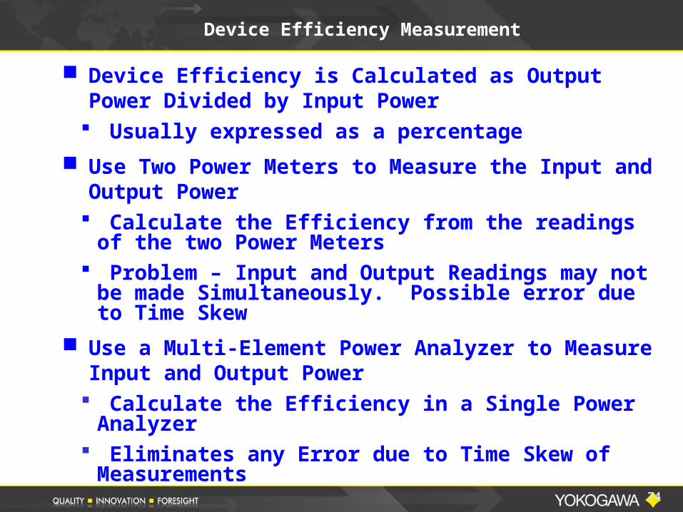
Device Efficiency Measurement
Device Efficiency is Calculated as Output Power Divided by Input Power Usually expressed as a percentage
Use Two Power Meters to Measure the Input and Output Power Calculate the Efficiency from the readings of
the two Power Meters Problem – Input and Output Readings may not
be made Simultaneously. Possible error due to Time Skew
Use a Multi-Element Power Analyzer to Measure Input and Output Power Calculate the Efficiency in a Single Power
Analyzer Eliminates any Error due to Time Skew of
Measurements
75
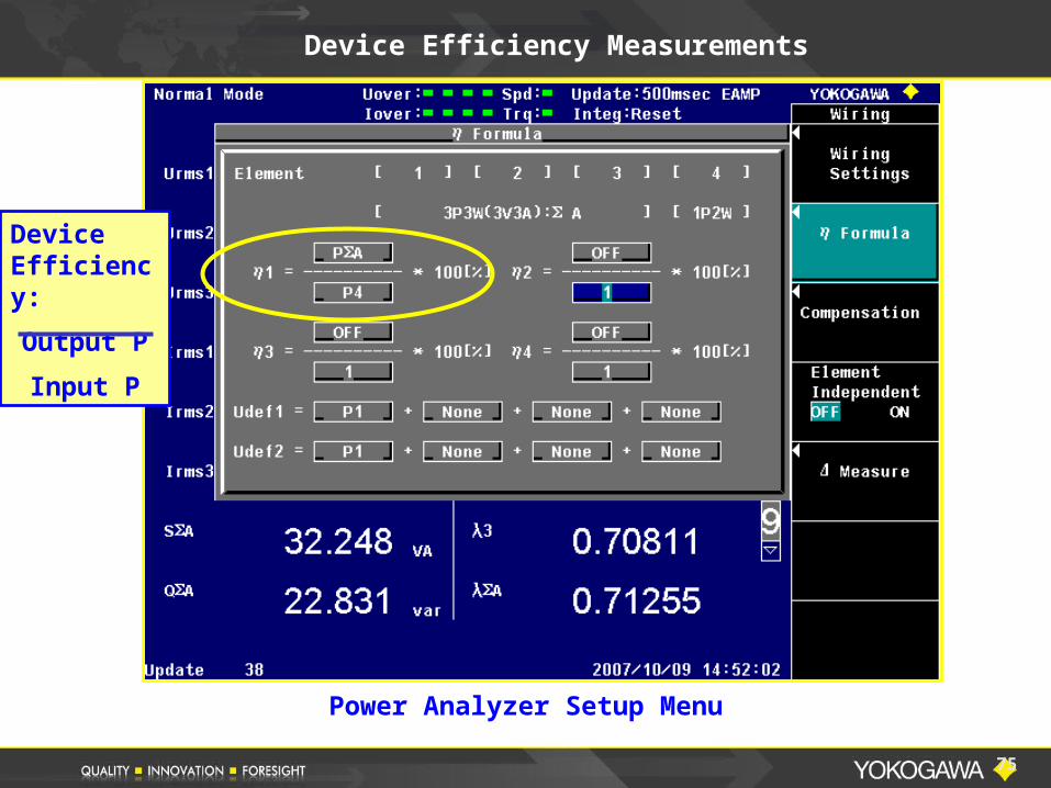
Device Efficiency Measurements
Device Efficiency:
Output P
Input P
Power Analyzer Setup Menu
76
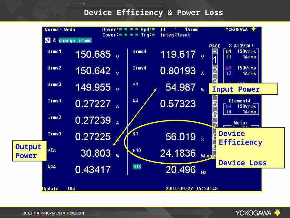
Device Efficiency & Power Loss
Device Efficiency
Device Loss
Input Power
Output Power
77
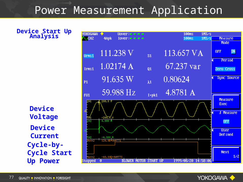
Power Measurement Application
Device Start UpAnalysis
Device Voltage
Device Current
Cycle-by-Cycle Start Up Power
78
Overview – Part III of III
PART III BASIC POWER
MEASUREMENTS using aDIGITAL OSCILLOSCOPE
79
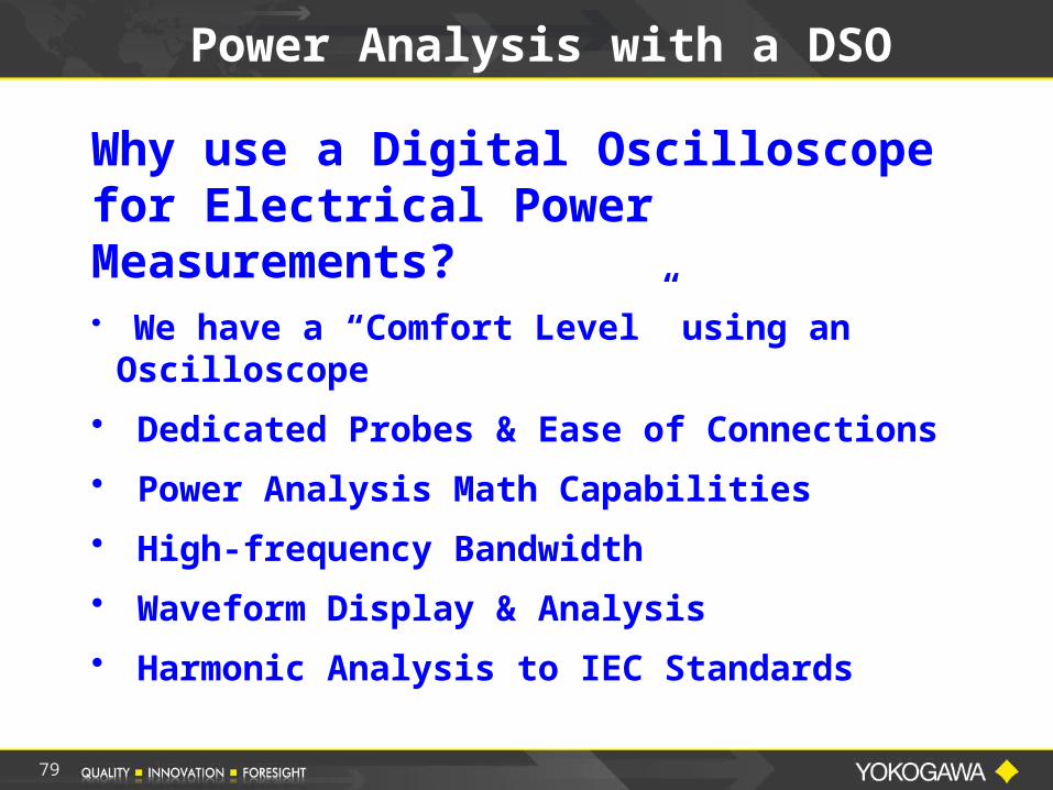
Power Analysis with a DSO
Why use a Digital Oscilloscope for Electrical Power Measurements?• We have a “Comfort Level” using an
Oscilloscope
• Dedicated Probes & Ease of Connections
• Power Analysis Math Capabilities
• High-frequency Bandwidth
• Waveform Display & Analysis
• Harmonic Analysis to IEC Standards
80
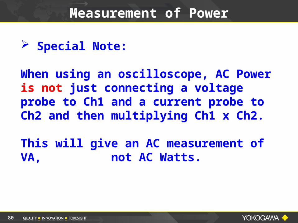
Special Note:
When using an oscilloscope, AC Power is not just connecting a voltage probe to Ch1 and a current probe to Ch2 and then multiplying Ch1 x Ch2.
This will give an AC measurement of VA, not AC Watts.
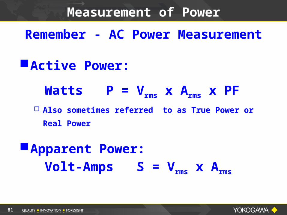
Measurement of Power
81
Measurement of Power
Remember - AC Power Measurement
Active Power:
Watts P = Vrms x Arms x PF
Also sometimes referred to as True Power or Real
Power
Apparent Power:Volt-Amps S = Vrms x Arms

82
Measurement of Power
Yokogawa Digital Power Scopes use the following method to calculate power:
Pavg = 1/T 0 v(t) * I (t) dt
Taking advantage of digitizing techniques, the INSTANTANEOUS VOLTAGE is multiplied by the INSTANTANEOUS CURRENT and then INTEGRATED over some time period.
T
83
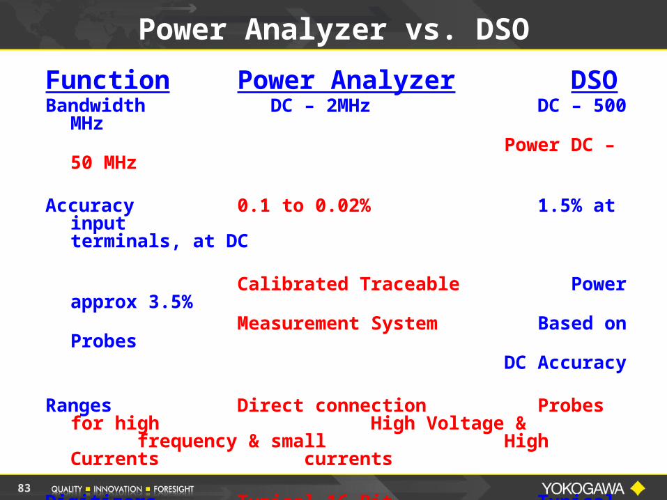
Power Analyzer vs. DSO
Function Power AnalyzerDSO
Bandwidth DC – 2MHzDC – 500 MHz
Power DC –50 MHz
Accuracy 0.1 to 0.02%1.5% at input
terminals, at DC
Calibrated TraceablePower approx 3.5%
Measurement SystemBased on Probes
DC Accuracy
Ranges Direct connection Probes for high
High Voltage & frequency & small High Currents
currents
Digitizers Typical 16-BitTypical 8-Bit
65,536 levels256 Levels
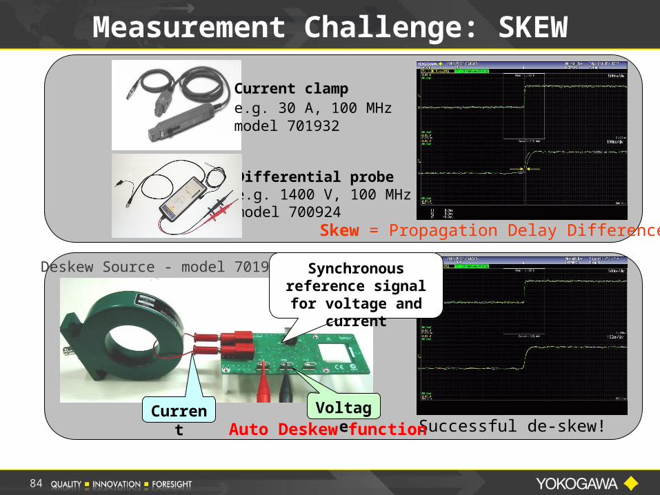
Skew = Propagation Delay Difference
Current clampe.g. 30 A, 100 MHz model 701932
Differential probee.g. 1400 V, 100 MHzmodel 700924
Successful de-skew!
Deskew Source - model 701936
Auto Deskew function
Measurement Challenge: SKEW
Synchronous reference signal for voltage and current
Current Voltage
84
85
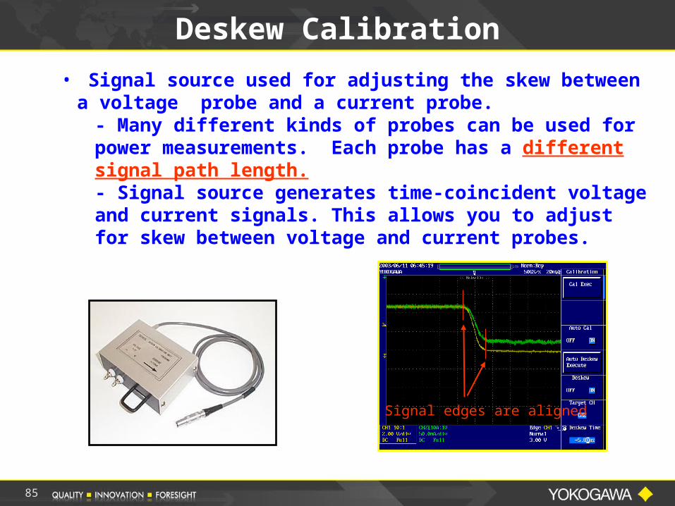
Signal edges are aligned
Deskew Calibration
• Signal source used for adjusting the skew between a voltage probe and a current probe.
- Many different kinds of probes can be used for power measurements. Each probe has a different signal path length.- Signal source generates time-coincident voltage and current signals. This allows you to adjust for skew between voltage and current probes.
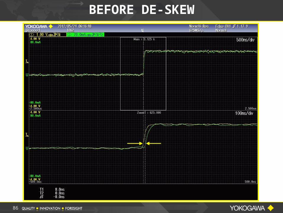
BEFORE DE-SKEW
86
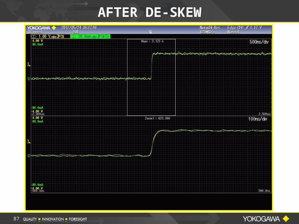
AFTER DE-SKEW
87
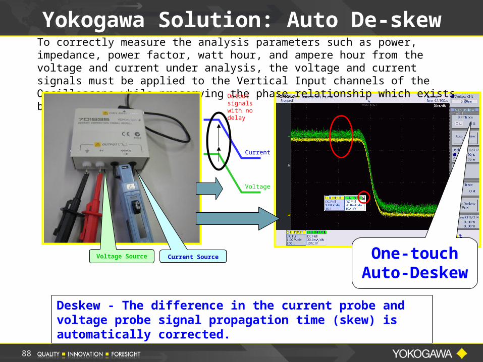
Deskew - The difference in the current probe and voltage probe signal propagation time (skew) is automatically corrected.
Yokogawa Solution: Auto De-skewTo correctly measure the analysis parameters such as power, impedance, power factor, watt hour, and ampere hour from the voltage and current under analysis, the voltage and current signals must be applied to the Vertical Input channels of the Oscilloscope while preserving the phase relationship which exists between U & I in the DUT.
One-touch Auto-Deskew
Voltage Source Current Source
Current
Voltage
Output signals with no delay
88
89
Power Analysis with a DSO
Typical Measurements
• Board Lever Power Measurements
• Switching Power Loss
• Device Power Consumption
• Switching Noise Level
• Harmonics
• Waveform Display & Analysis
• Inrush & Transients
90
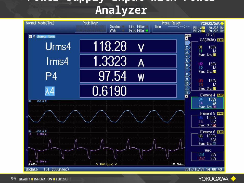
Power Supply Input with Power Analyzer
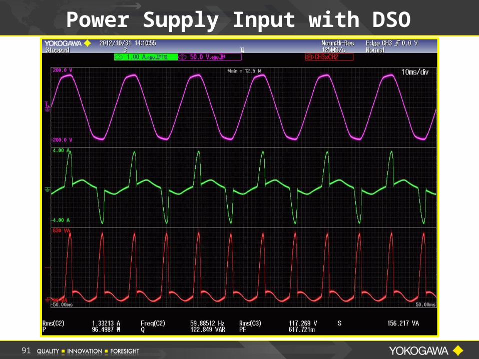
Power Supply Input with DSO
91
92
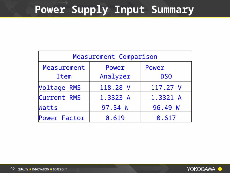
Power Supply Input Summary
Measurement Comparison
Measurement Item Power Analyzer Power DSO
Voltage RMS 118.28 V 117.27 V
Current RMS 1.3323 A 1.3321 A
Watts 97.54 W 96.49 W
Power Factor 0.619 0.617
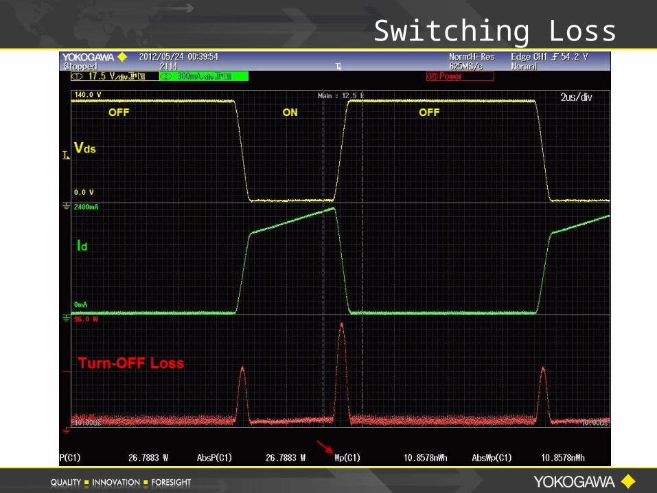
Switching Loss
94
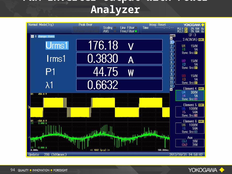
PWM Inverter Output with Power Analyzer
95
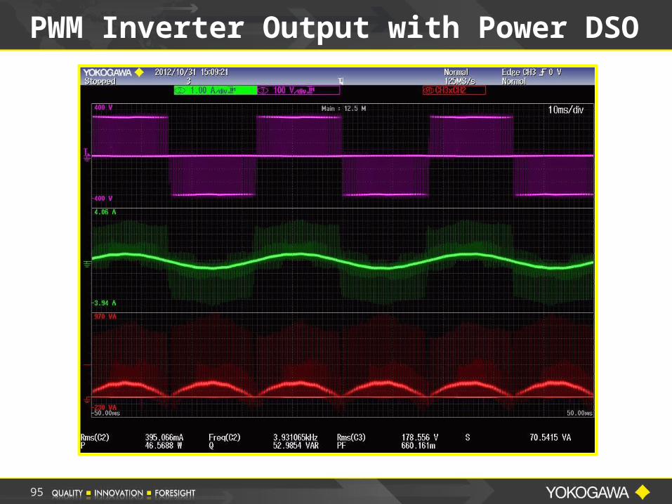
PWM Inverter Output with Power DSO
96
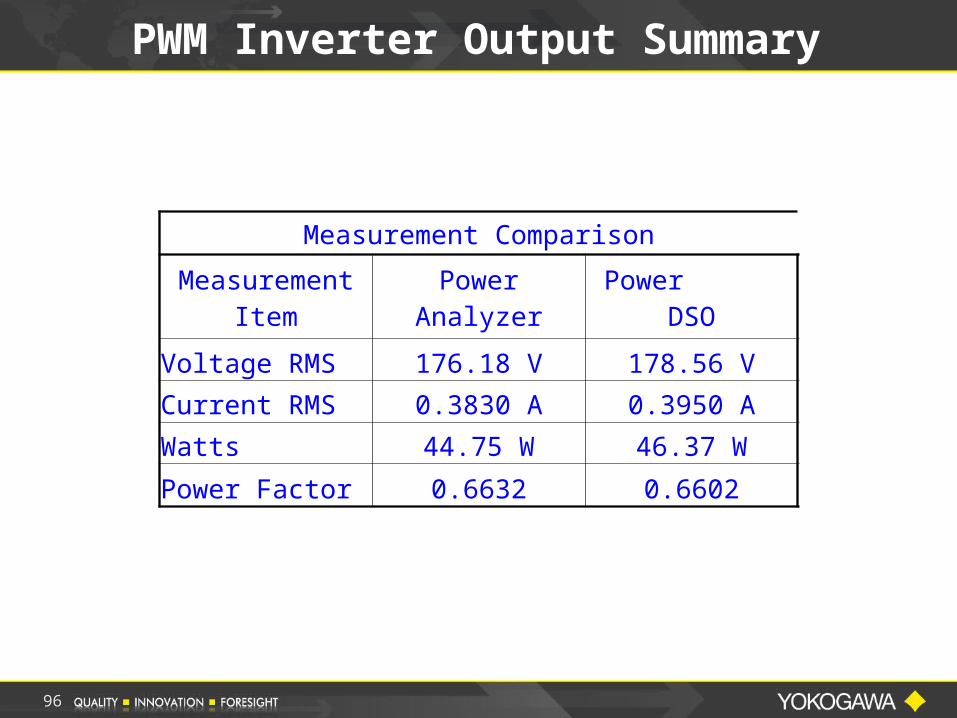
Measurement Comparison
Measurement Item Power Analyzer Power DSO
Voltage RMS 176.18 V 178.56 V
Current RMS 0.3830 A 0.3950 A
Watts 44.75 W 46.37 W
Power Factor 0.6632 0.6602
PWM Inverter Output Summary
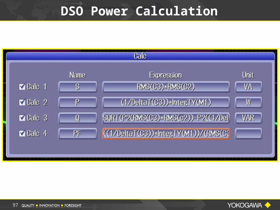
DSO Power Calculation
97
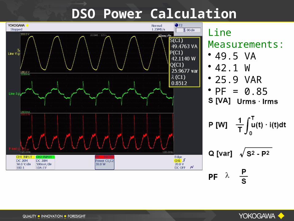
DSO Power CalculationLine Measurements:• 49.5 VA• 42.1 W• 25.9 VAR• PF = 0.85
PF
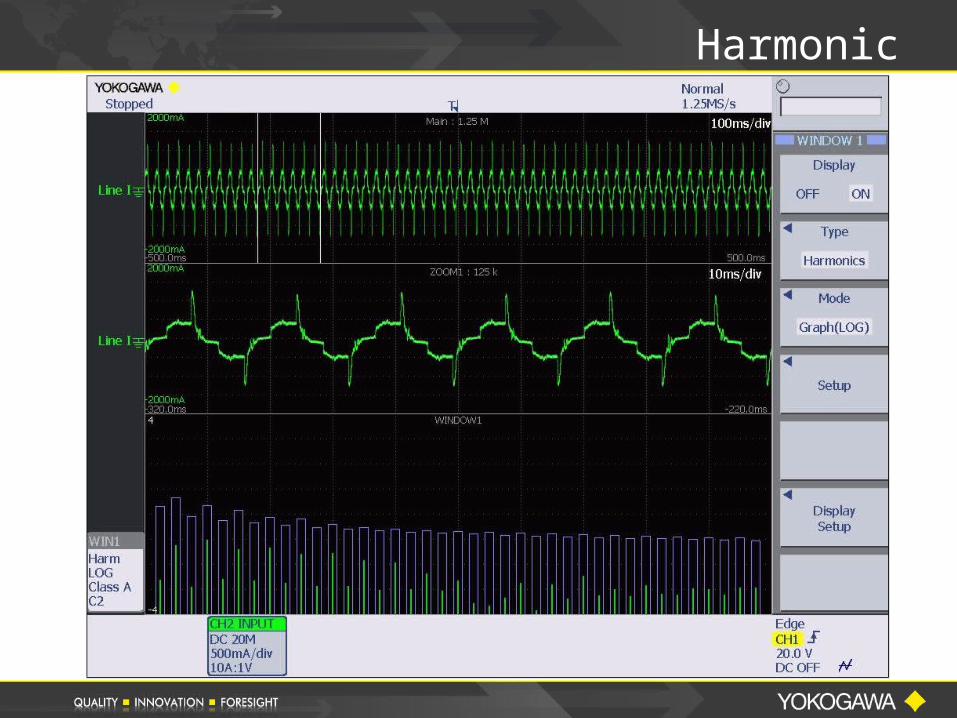
Harmonic
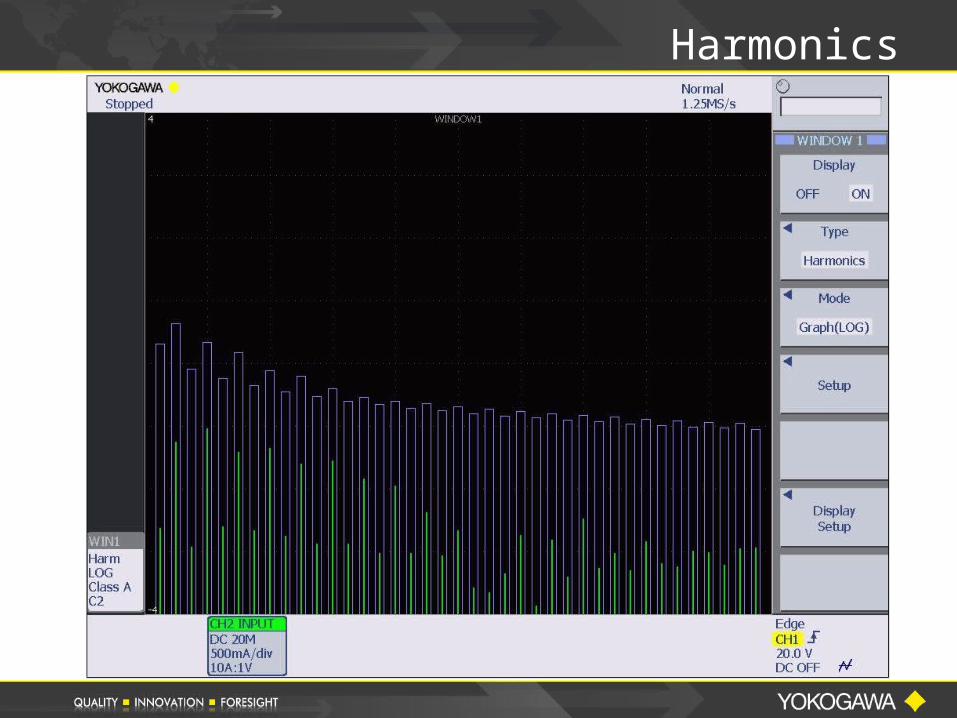
Harmonics
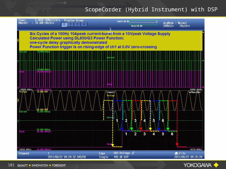
ScopeCorder (Hybrid Instrument) with DSP
101
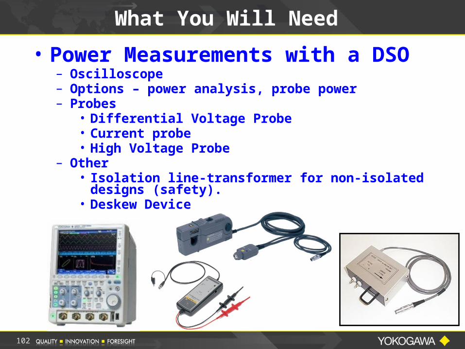
• Power Measurements with a DSO– Oscilloscope– Options – power analysis, probe power– Probes
• Differential Voltage Probe• Current probe• High Voltage Probe
– Other• Isolation line-transformer for non-isolated
designs (safety).• Deskew Device
What You Will Need
102

103
Yokogawa offers the Most Complete Line of Power Measurement Products to meet the customers Application and Budget.
Product, Application and Software support provided from a network of Field Sales Reps, Factory Regional Sales Managers and Factory Support Engineers.
NIST Traceable Calibration provided by Factory Trained technicians in Newnan, GA.
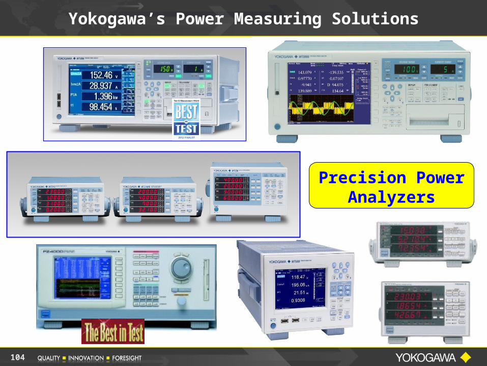
Yokogawa’s Power Measuring Solutions
104
Yokogawa’s Power Measuring Solutions
Precision Power Analyzers
105
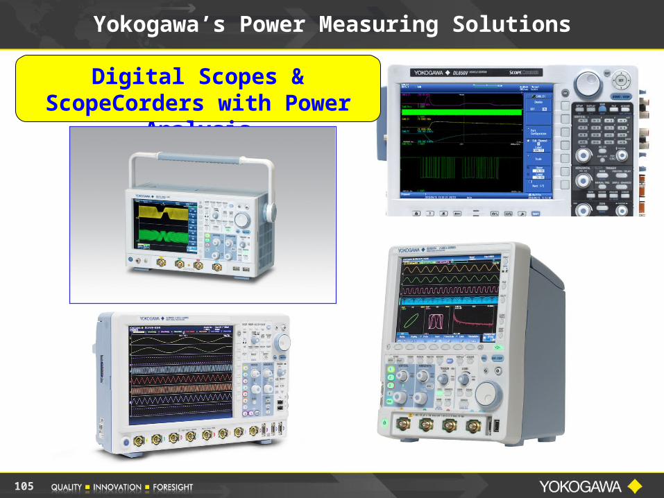
Digital Scopes & ScopeCorders with Power
Analysis
Yokogawa’s Power Measuring Solutions
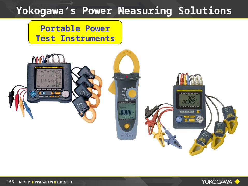
Portable Power Test Instruments
Yokogawa’s Power Measuring Solutions
106
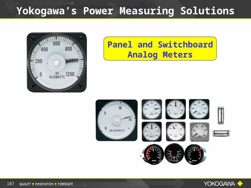
Panel and Switchboard Analog
Meters
Yokogawa’s Power Measuring Solutions
107
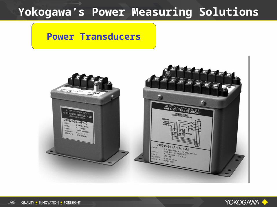
Power Transducers
Yokogawa’s Power Measuring Solutions
108
Multi Function Digital Meters
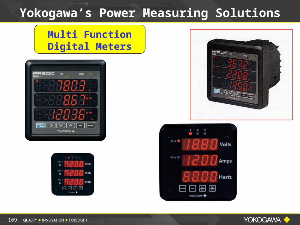
Yokogawa’s Power Measuring Solutions
109
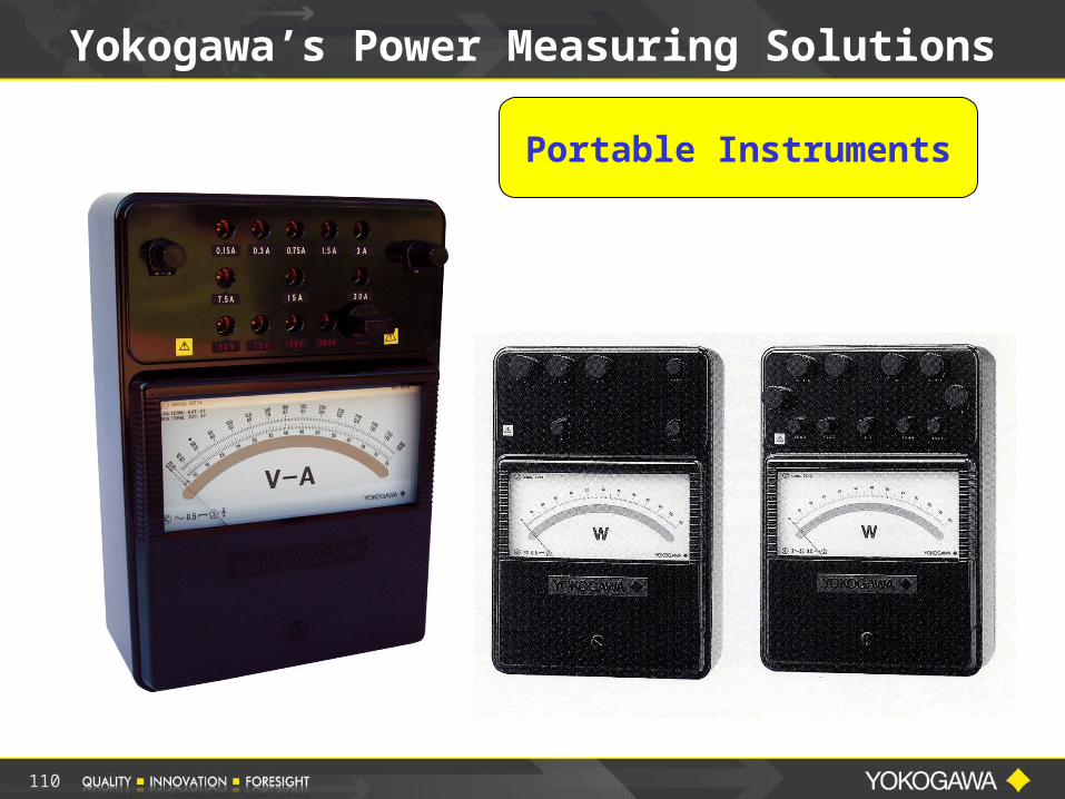
Portable Instruments
Yokogawa’s Power Measuring Solutions
110
111
Overview - What We Hope You Learned
Helped You With a Better Understanding of Electrical Power Measurements
Review of Some of the Basics
Power Measurements Using a Precision Power Analyzer and Digital Oscilloscope Single-Phase Power Measurements
Current Sensors
Three-Phase Power Measurements
2 & 3 Wattmeter Method
112
Part II: Power Factor Measurements
Displacement Power Factor
True Power Factor
Power Factor Measurements in Single-Phase & Three-Phase Circuits
Practical Power Factor Measurement Applications
Overview - What We Hope You Learned
113
Part III: Power Measurements using a Digital Oscilloscope How to properly use a Digital
Oscilloscope to make Electrical Power Measurements
De Skew Operation Measurement Examples on a Power
Supply Input and a PWM Inverter Output Measurement Comparison between the
DSO and a Power Analyzer
Answer your questions concerning Electrical Power Measurements
Overview - What We Hope You Learned
114
Invitation to Power Measurement Webinars
Power Analysis: Precision AC Power Measurements This one hour seminar will cover Precision Power Measurements and Power Factor Measurements.
Power Measurement & Harmonic Analysis This 1-hour seminar is packed with tips and techniques for making accurate power measurements on distorted waveforms like from a Power Supply, Electronic Ballast and Variable Speed PWM Motor Drive. We will also cover methods for making and analyzing the harmonic content of various power waveforms.
Advances in Precision Electrical Power Measurement This informative Webinar covers new measurement techniques and solutions for making precision power measurements to improve product performance and efficiency designs.
Back to the Basics of Electrical Power Measurement Target audience is Engineers and Technicians that need to make Power Measurements but may not be experts in the field or may need a refresher course.
Power Analysis: Precision AC Power Measurements This webinar will cover Precision Power Measurements and Power Factor Measurements.
Digital Oscilloscope Power Analysis In this 1-hour seminar you will be introduced to the many specialized power measurements necessary to evaluate switched-mode power supplies.
Requirements and Easy Solutions for Standby Power Measurements This 30-minute Webinar discusses the area of Standby Power Measurements.
Power Measurement and Analysis Power measurement requires much more than a simple measurement of voltage and current, requiring phase angle as well as harmonic distortion. Government regulations exist for both. (not yet online)
Fundamentals of Electrical Power Measurements This one hour webinar will provide attendees with Solutions and Education for making Electrical Power Measurements.

115
Webinars & Webinars On Demand
Join Us for Future Web Seminars
Visit our Web Site
http://tmi.yokogawa.com/us/technical-library/seminars-webcasts/

116
Yokogawa Corp of America Test & Measurement
Div. 2 Dart Rd.
Newnan, GA 30265
tmi.yokogawa.com Tel: 1-800-888-6400 Barry BollingApplication EngineerExt 2538
Thank You & Contact Info