Embed Size (px)
Citation preview

Frontiers of FusionMaterials Science
Presented by S.J. Zinkle,
Oak Ridge National Laboratory
Office of Fusion Energy SciencesBudget Planning meeting
March 13, 2001
Gaithersburg, MD

INTRODUCTION
¥The mission of the Fusion Materials Sciences programis to ÒAdvance the materials science base for the development ofinnovative materials and fabrication methods that will establishthe technological viability of fusion energy and enable improvedperformance, enhanced safety, and reduced overall fusion systemcosts so as to permit fusion to reach its full potentialÓÐResearch performed on structural materials (alloys and
ceramic composites), insulators, etc.
¥TodayÕs presentation: Materials science highlightsÐSimultaneous scientific excellence: research directly relevant
for fusion and of interest to the broader (materials) sciencecommunity

Fusion Materials Science ProgramTheory-Experiment Coordinating Group*
MicrostructuralStability
Physical &MechanicalProperties
Fracture &DeformationMechanisms
Corrosion andCompatibilityPhenomena
Fabricationand Joining
ScienceMaterials for AttractiveFusion Energy• Structural Alloys*
- Vanadium Alloys- F/M and ODS Steels- High T Refractory Alloys- Exploratory Alloys
• Ceramic Composites*- SiC/SiC, other CFCs
• Coatings• Breeder/multiplier
Materials• Neutron Source Facilities
Materials for Near-Term FusionExperiments• PFMs (Refractory
Alloys, etc.)• Copper Alloys• Ceramic Insulators• Optical Materials
*asterisk denotes Fusion Materials Task Group

Fusion Materials Sciences R&D Portfolio
¥ Large emphasis on mechanical properties
MicrostructurePhys./Mech. PropsDeformation/FractureCorrosion/CompatibilityFabrication/joiningIFMIF

Investigation of Thermal Creep Mechanisms in V-4Cr-4Ti
Diffusion-ControlledCreep Mechanisms
ε σkT
DGbA
b
d G
m n
=
Mechan ism D n A mClim b of Ed ge Disl oca tions DL 5 6x10⁷ 0Visco us Glid e (Mi cro creep) DS 3 6 0Low-Te mperatur e Climb Dd 7 2x10⁸ 0Harpe r-Dorn DL 1 3x10⁻¹⁰ 0Nabarro- Herri ng DL 1 12 2Cobl e Db 1 100 3GBS (Supe rplasti city ) Db 2 200 2Nabarro-S ubg rai n DL 1 12 2Nabarro- Bardeen-H errin g DL 3 10 0 10- 1 2
10- 1 1
10- 1 0
10- 9
10- 8
10- 7
10- 6
10- 5
10- 4 10- 3 10- 2
873 Uniaxial923 Uniaxial973973 Uniaxial998 Uniaxial10731073 Uniaxial973 (V-3Fe-4Ti)1073 (V-3Fe-4Ti)
(dε/
dt)k
T/D
Gb
σ/G
Temperature, K
n = 7
n = 1
10- 6
10- 5
0.0001
0.001
0.01
0.1
0 0.2 0.4 0.6 0.8 1
Nor
mal
ized
She
ar S
tres
s,
τ /µ
(20˚
C)
Normalized Temperature, T/TM
Elastic regime(dε/dt<10-8 s-1)
Coble creep
Dislocation creep
N-Hcreep
Dislocation glide
Theoretical shear stress limit
20˚C 400˚C 700˚C
15
150
Uni
axia
l T
ensi
le S
tres
s, M
Pa
1.5
0.15
1500
10-8 s-1, L=20 µm
10- 6
10- 5
0.0001
0.001
0.01
0.1
0 0.2 0.4 0.6 0.8 1
Nor
mal
ized
She
ar S
tres
s,
τ /µ
(20˚
C)
Normalized Temperature, T/TM
Elastic regime(dε/dt<10-4 s-1)
Dislocation creep
N-Hcreep
Dislocation glide
Theoretical shear stress limit
20˚C 400˚C 700˚C
15
150
Uni
axia
l T
ensi
le S
tres
s, M
Pa
1.5
0.15
1500
10-4 s-1, L=20 µm
ε µ= =− −10 204 1s m, L
Deformation Mechanism Maps for V-4Cr-4Tiε µ= =− −10 208 1s m, L
Experimental Creep Data
PNNL / ORNL / ANL / UCSB collaboration

The R&D portfolio of the fusion materials scienceprogram has two general guiding features
¥Provide a valuable product for fusion energy sciences(build knowledge base on key feasibility issues)
¥Provide excellence in materials scienceÐThis also helps to build support for fusion energy within the
broad materials science community
Topic Fusion benefit Science aspectDisplacementcascades
Quantification of displacementdamage source term
• I s the concept of a liquid validfor time scales of only a fewlattice vibrations
• T ransient (ps) electron-phononcoupling physics
Defect migration Radiation damage accumulationkinetics
• 1 D vs. 3D diffusion processes• i onization-induced diffusion
(nonmetals)Structural materialoperating limits
Identify/expand operatingtemperature window andmechanical stress capabilities
• T hermal creep mechanisms• D islocation-defect interactions
V-4Cr-4Ti R&D Roadmap Snapshot1990 1995 2000 2005 2010
PHYSICAL/MECHANICAL PROPERTIES:Unirradiated:
Tensile propertiesThermal conductivityElectrical conductivitySpecific heatCoeff. thermal expansionFracture toughnessThermal creep
Irradiated (1-30 dpa)Tensile properties (100-600°C)
(600-750C)Thermal creep with fusion-relevant He
(He embrittlement) (?)Fracture toughness Tirr ≤400°C
400-700°CMicrostructural stability 100-600°CIrradiation creep - 200-500°C
500-700°CChemical compatibility with coolants
LithiumPb-LiHeliumSn-Li (?)Flibe (?)
JoiningThick plate lab welds (DBTT ≤0°C)Field welds (friction stir welding?)
MHD insulatorsInitial screeningChemical compatibility 400-700°CIn-situ formation/self-healing
Fusion Materials Science is Strongly Integrated withother Materials Science programs (research synergy)
¥ No one engaged in fusion materials research is supported 100% byOFES funding; all fusion materials scientists actively interact withother research communities
¥ BES (ceramic composites, radiation effects in materials, electron microscopy,deformation physics, nanoscale materials)
¥ NERI (deformation mechanisms in irradiated materials, damage-resistant alloys)¥ NEPO (mechanical behavior of reactor core internal structure)¥ EMSP program (radiation effects in nuclear waste materials, including modeling
relevant for SiC and other ceramics)¥ Naval programs (radiation effects in SiC/SiC, refractory alloys, cladding
materials)¥ NRC (fracture mechanics and radiation effects in pressure vessel alloys)¥ EPRI (stress corrosion cracking in alloys)¥ APT, SNS (effects of He and radiation damage on structural integrity of
materials)¥ Defense programs (stockpile stewardship materials issues)

Atomistic simulations model the unit interaction of anedge dislocation with a radiation-induced defect cluster
The simulations are in excellent qualitative agreement with experiments
Experimental TEM imageby Ian Robertson at UIUC
MD simulation by Brian Wirth at LLNL
Atomistic simulations supported by OFES and ASCI,In-situ TEM supported by OBES

Fusion Materials Scientists are Contributing tothe Resolution of Several Grand Challenges in
the General Field of Materials Science
¥ What are the maximum limits in strength and toughness formaterials?
Ð Dislocation propagation, interaction with matrix obstacles
¥ How are the ÒlawsÓ of materials science altered under nanoscaleand/or nonequilibrium conditions
Ð Critical dimensions for dislocation multiplicationÐ Nonequilibrium thermodynamics
¥ What is the correct physical description of electron and phonontransport and scattering in materials?
Ð Thermal and electrical conductivity degradation due to point, line and planardefects
¥ What is the effect of crystal structure (or noncrystallinity) on theproperties of matter?

Radiation damage is inherently multiscale with interacting phenomena ranging from ps-decades and nm-m

Nanoscience appears in numerous places in the fusionmaterials science program
3-D atom probe iso-composition contour(Y, Ti, O) for nanocomposited ferritic steel
Nanoscale self-organization of defectclusters in neutron-irradiated Ni
Atomic resolution analysis of crystal-amorphous transition in SiC
Crack-deflecting interfaces in ceramiccomposites give improved toughness
300 nm
SiC fiber
SiC SiC multilayersmultilayers
10 nm
Microcrack
Amorphousnanoscale
region
200 nm

Experimental evidence for nanoscale melting during atomiccollisions has been obtained
2400
2800
2000
1600
1200
800
400ZrO2 SiO2
20 40 60 80
ZrO2m+
ZrSiO4
ZrO2t+
ZrSiO4
ZrSiO4 + α-quartz
ZrSiO4 + β-quartz
ZrSiO4 + tridymite
ZrSiO4 + cristobalite
ZrO2t + SiO2liq
ZrO2t + cristobalite
liquidZrO2c+liquid
two liquids
ZrO2-SiO2 Phase Diagram
Mole Percent SiO2
Tem
pera
ture
(¡C
)
Nature, vol. 395, Sept 5. 1998, p. 565 nm
111
200
220
311
Microstructure of Zircon Irradiated at 800 °C
Tetragonal ZrO2

One of the Most Important Scientific Results From the US/Japan Collaborationson Fusion Materials has been the Demonstration of Equivalency of DisplacementDamage Produced by Fission and Fusion Neutrons
Fission(0.1 - 3 MeV)
A critical unanswered question is the effectof higher transmutant H and He
production in the fusion spectrum
5 nmPeak damage state iniron cascades at 100K
50 keV PKA(ave. fusion)
10 keV PKA(ave. fission)
MD computer simulations show that subcascades anddefect production are comparable for fission and fusion
Similar defect clusters produced by fission andfusion neutrons as observed by TEM
Fusion(14 MeV)
Similar hardening behavior confirms the equivalency

Displacement Damage Mechanisms are beinginvestigated with Molecular Dynamics Simulations
PKAs oriented in the close packedplanes produce enhanced damageefficiency at low energies compared toother orientations, due to a planardefect creation process
Damage efficiency saturates whensubcascade formation occurs
300 eV PKA
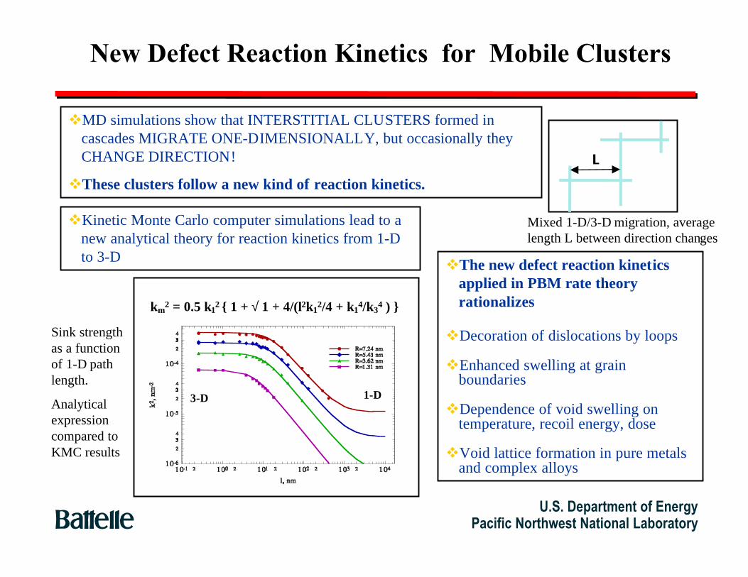
New Defect Reaction Kinetics for Mobile Clusters
vMD simulations show that INTERSTITIAL CLUSTERS formed incascades MIGRATE ONE-DIMENSIONALLY, but occasionally theyCHANGE DIRECTION!
vThese clusters follow a new kind of reaction kinetics.
vKinetic Monte Carlo computer simulations lead to anew analytical theory for reaction kinetics from 1-Dto 3-D vThe new defect reaction kinetics
applied in PBM rate theoryrationalizes
vDecoration of dislocations by loops
vEnhanced swelling at grainboundaries
vDependence of void swelling ontemperature, recoil energy, dose
vVoid lattice formation in pure metalsand complex alloys
L
Mixed 1-D/3-D migration, averagelength L between direction changes
km2 = 0.5 k12 1 + √ 1 + 4/(l2k1
2/4 + k14/k3
4 )
Sink strengthas a functionof 1-D pathlength.
Analyticalexpressioncompared toKMC results
3-D 1-D
U.S. Department of EnergyPacific Northwest National Laboratory

Experimental investigation ofstacking fault energies of BCC metals
1019
1020
1021
1022
1023
1024
100 200 300 400 500 600
Measured Defect Cluster Densities in V-4Cr-4Ti Neutron-irradiated to 0.5 dpa
Clu
ster
Den
sity
(m
-3)
Irradiation Temperature
faulted loops
perfect loops
Ti(O,C,N)precipitates 0
0.2
0.4
0.6
0.8
1
1.2
1.4
10 100 1000 104
Continuum mechanics calculation of dislocation loop energies in vanadium
Dis
loca
tion
loop
ene
rgy
(eV
/SIA
)Number of SIAs
Perfect loop
Faulted loop, γS F
=1.2 J/m 2
γS F
=0.8 J/m 2
d=1.2 nm d=2.5 nm

Determination of interstitial migration energies in ceramics
• S olve steady state rate eqns:
Dd C
dxC C D C C P
Dd C
dxC C D C C P
ii
i v i i s
vv
i v v v s
2
2
2
2
0
0
− − + =
− − + =
α
α
• F or sink-dominant conditions (CS>1014/m2),the defect-free zone width is related to thediffusivity (Di) and damage rate (P) by:
Di =L P
Cicrit Cs
Defect-free zones in ion-irradiated MgAl2O4
Defect-free grain boundaryzones in ion-irradiated Al2O3
10-9
10-8
10-7
10-6
10-5
10 15 20 25 30 35 40
Interstitial Diffusion Coefficient in Ion Irradiated Oxides Determined From Defect-Free Zone Widths at Grain Boundaries
Inte
rstit
ial D
iffus
ion
Coe
ffici
ent
(m2-s
-1)
1/kT (eV)-1
MgAl2O
4
Eim
~0.21 eV
Al2O
3

Ionizing Radiation can induce a myriad of effectsin ceramics
¥Defect productionÐRadiolysis (SiO2, alkali halides)ÐIon track damage (swift heavy ions)
¥Defect annealing and coalescence (ionization-induceddiffusion)ÐAthermal defect migration is possible in some materials

Highly ionizing radiation (dEioniz./dx > 7 keV/nm)introduces new damage production mechanisms
Swift heavy ions induce surfaceprotrusions and amorphizationIon tracks produce displacement
damage via inelastic atomic events
430 430 MeV MeV Kr –>MgAlKr –>MgAl 22OO44
430 430 MeV MeV Kr –>MgAlKr –>MgAl 22OO44
710 710 MeV BiMeV Bi –>Al –>Al22OO33
710 710 MeV BiMeV Bi –>Si –>Si33NN44
3.5 3.5 nm diamnm diam..amorphous coreamorphous core

Investigation of ionization-induced diffusion in ceramics
1017
1018
1019
1020
1021
1022
1023
10 100 1000 104
Loop
Den
sity
(m
-3)
Electron-hole pairs/dpa Ratio
ZrFe
Fe
Mg Al
Al
Mg
C C He He H
650˚C10- 6 to 10 - 4 dpa/s
Fe Al
C
He
H
H
Al2O
3MgAl
2O
4
Zr
Mg
Fe
MgOHe
H
Mg
0
10
20
30
40
50
10 100 1000 104 105
Loop
Dia
met
er (
nm)
Electron-hole pairs/dpa Ratio
Al
C
He
650˚C10-7 to 10-4 dpa/s
Fe
H
Al2O
3
MgAl2O
4
HHe
Mg
MgO
H (d~200 nm)
0.1 µm
Aligned cavities in Al2O3 ion-irradiated at 25˚C(Al/O/He ion irradiation, >500 eln.-hole pairs per dpa)
proj. [0001]proj. [0001]
Large interstitial loops in MgAl 2O4 ion-irradiated at25˚C for regions with >100 eln.-hole pairs per dpa

Irradiated materials undergo plastic instabilityand failure due to dislocation channel formation
Outstanding questions :• What governs the appearance of a yield point?• What governs the dose dependence of yield point onset?• What governs dislocation channel initiation?• What governs dislocation channel growth? (cross-slip in fcc metals is not well understood)• What controls channel width?
Plastic flow localization in irradiated metals - An unresolved issue for >30 yrs

02
000
4000
Z( a)
02
000
4000
X(a
)
0 1 000 2 000 3000 4000Y (a)
b
225MPa
145MPa
Dislocation Dynamics (DD) is a new computer simulationmethod developed at UCLA for modeling fundamentalmicroscopic mechanical properties
New Understanding (dislocation-defect interactions):(a) Local heating destroys vacancy clusters;(b) Shape instabilities allow dislocations to overcomethe resistance of SIA clusters.
[-1 1 0] (a)
[-1-1
2]
(a)
-500 0 500-1200
-1100
-1000
-900
-800
-700
-600
bc
b
Leads to localized flow
Leads to yield drop
(1) N.M. Ghoniem, B. N. Singh, L. Z. Sun, and T. Diaz de laRubia, J. Nucl. Mater, 276: 166-177 (2000).(2) N.M. Ghoniem, S.- H. Tong, B.N. Singh, and L. Z. Sun,Phil. Mag., 2001, submitted
Broad Objectives of DD:1. Understand fundamental deformation mechanisms2. Provide a physical basis for plasticity3. Determine stress-strain behavior without assumptions.4. Design new ultra-strong and super-ductile materials.

Plastic flow localization in defect free bands appearsin the Dislocation Dynamics (DD) simulations
The implementation of cross-slip into DD gives rise to the formation ofdefect free bands (channels) with a width of 200-300 nm
Spreading of the channels isrestrained by the formationof dipole segments and theremaining radiation induceddefect distribution
Nature, August 24, 2000

Successful Applications in FusionMaterial Science (2) UCLA-RISO (Denmark) collaboration onlocalization of plastic flow
Computer Simulations Experiments on Irradiated Cu

0
100
200
300
400
500
600
700
0 0.05 0.1 0.15 0.2 0.25 0.3
Load-Elongation Curves for V-4Cr-4Ti Irradiated in HFBR to 0.5 dpa
Engi
neer
ing
Stre
ss, M
Pa
Normalized Crosshead Displacement, mm/mm
110˚C 270˚C
325˚C
420˚C
Tt e s t
~Tirr
100 nm100 nm
TTtesttest =T=Tirrirr =270˚C=270˚C
g=011g=011
Irradiated Materials Suffer Plastic Instabilitydue to Dislocation Channeling

0.3
Unirradiated
0.010.10.2
Unirradiated
0.01
0.1
0.20.3
Yield point formed
As-Irradiated Post-Irradiation Annealed350¡C/50 hrsPure Copper
Deformation Behavior in As-Irradiated and Post-IrradiationAnnealed Pure Copper (PNNL & Ris¿ National Laboratory)
Post-Irradiation Annealed Condition¥ Dislocation cell structure: material deforms
homogeneously at 0.01 dpa¥ Mixture of channeling and homogeneous
deformation at 0.3 dpa
As-Irradiated, 0.3 dpa¥ Cleared channels with little to no dislocation movement
between the channels; localized deformation¥ Large increases in strength (6 to 8x)¥ Loss of uniform elongation and work hardening capacity¥ Formation of a clearly defined yield point
U.S. Department of EnergyPacific Northwest National Laboratory
PI Annealed, 0.01 dpa PI Annealed, 0.3 dpa

Deformation mechanisms in FCC metals
10-6
10-5
10-4
10-3
10-2
10-1
0 0.2 0.4 0.6 0.8 1
Deformation Map for 316 Stainless SteelIrradiated to 1 dpa
Nor
mal
ized
She
ar S
tres
s,
τ/µ(
20˚C
)
Normalized Temperature, T/TM
Elastic regime(dε/dt<10-8 s-1)
Coble creep
Dislocation creep
Dislocation glide
Theoretical shear stress limit
20˚C 300˚C 650˚C
24
240
Uni
axia
l T
ensi
le S
tres
s, M
Pa
2.4
0.24
2400
10- 8 s- 1, L=50 µm
N-H creep
Twinning
10-6
10-5
10-4
10-3
10-2
10-1
0 0.2 0.4 0.6 0.8 1
Deformation Map for 316 Stainless Steel
Nor
mal
ized
She
ar S
tres
s,
τ/µ(
20˚C
)
Normalized Temperature, T/TM
Elastic regime(dε/dt<10 -8 s-1)
Coble creep
Dislocation creepDislocation glide
Theoretical shear stress limit
20˚C 300˚C 650˚C
24
240
Uni
axia
l T
ensi
le S
tres
s, M
Pa
2.4
0.24
2400
10- 8 s- 1, L=50 µm
N-H creep
Twinning
Irradiation is a useful tool to producecontrolled microstructures fordeformation mechanics studies
Channeling (Disln glide) occurs at highertemperatures (~300ûC)
Twinning occursat lower
temperatures(<200ûC) and high
strain rates

Unir
Deformation Flow Instability-Localization¥ Understanding uniform strain loss-flow localization requires close integration of
mult iscale models & experiments. In many cases irradiation may enhancefunctional strength.
Nano MacroMicroσcrss
0.00
0.05
0.10
0.15
0.20
0.25
200 300 400 500 600 700 800 900
σy
φt
n =0.2
n =0.4
n =0.5 n σy
-0.2
0
0.2
0.4
0 0.02 0.04 0.06 0.08 0.1 0.12 0.14
n
hp/Loo
V unirradiated
V irradiated
strain softening?
0
100
200
300
400
500
600
700
0 0.05 0.1 0.15 0.2 0.25 0.3 0.35
nv-newp1/VNC02d
Nom
inal
Str
ess
F/A o (
MP
a)
Nominal Strain, u/lo
Tensile test
FEA
0
100
200
300
400
500
600
700
800
0 0.05 0.1 0.15 0.2nvnewp2/nvnewd
σ (M
Pa)
ε
Tensile test 3-Dshape imaging andFEA modeling
True σ−ε
Irr
Multiscale Physics
Eng s-e
Engr s-e Instability Theory
flow channel
Exp.
FEA
nP
∆
Beam Bend Tests
FEAIrr
Unirr
Hardness Pile-up/n
Unirr
Irr
εhard
εsoft
σ
ε
s
eFEA
0
-
+
σy
Macro
εu
Confocal microscopy

Recent work at ORNL suggests that thermodynamicsmay be significantly altered at the nanoscale
Atomic analysis of new nanocompositedferritic steel provides clues to itsoutstanding creep strength (6 orders ofmagnitude lower creep rate thanconventional steels at 600-900ûC)
Atomic composition of nanoclusters
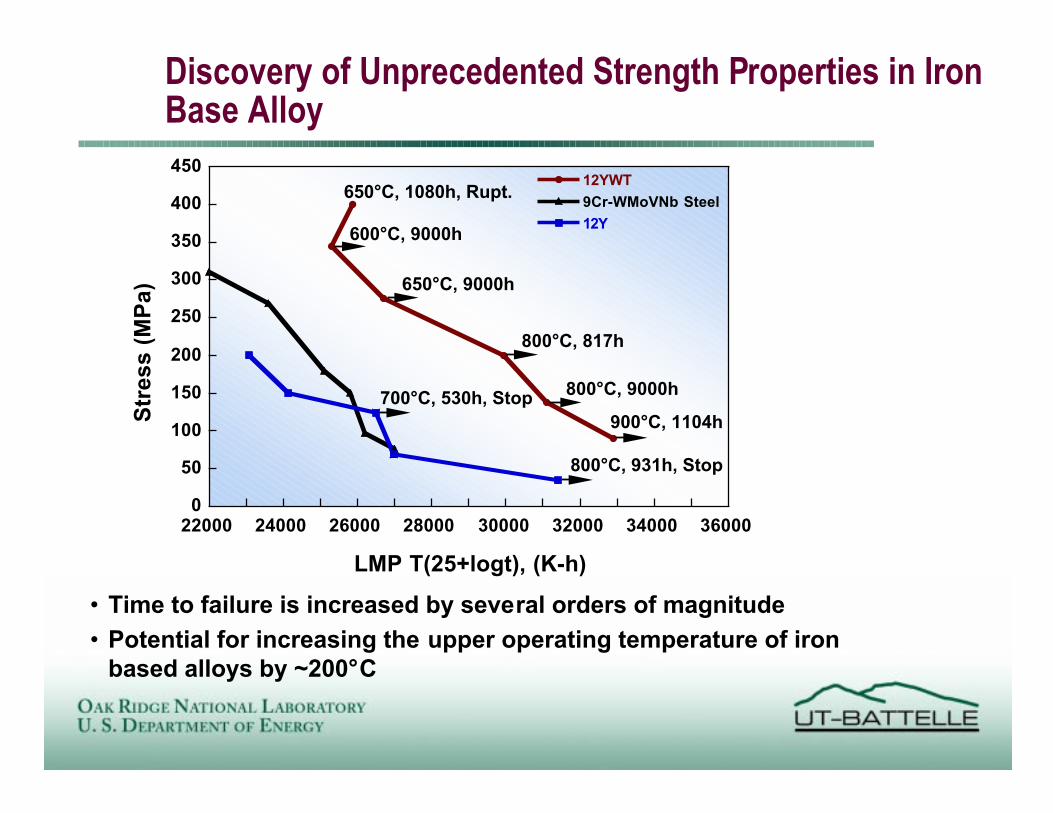
Discovery of Unprecedented Strength Properties in IronBase Alloy
0
50
100
150
200
250
300
350
400
450
22000 24000 26000 28000 30000 32000 34000 36000
12YWT
9Cr-WMoVNb Steel
12Y
LMP T(25+logt), (K-h)
Str
ess
(MP
a)
700¡C, 530h, Stop
800¡C, 931h, Stop
900¡C, 1104h
800¡C, 9000h
800¡C, 817h
650¡C, 9000h
600¡C, 9000h
650¡C, 1080h, Rupt.
¥ Time to failure is increased by several orders of magnitude
¥ Potential for increasing the upper operating temperature of ironbased alloys by ~200¡C

Multiphysics - Multiscale Fracture Modeling - I10 m
10-10 m
10-2 m
10-3 m
Macroscopic Scale
structure
Mesoscopic Scale
FEM: blunting fields
FEM: load-displacement
Large scale bridging
Trigger particle mechanicsσ* = Kmicro/C√πa
Elastic-plastic deformation and fracture of acracked body as a function of temperatureand loading rate as characterized bymaterial macro constitutive and fracturetoughness properties.specimen
Local multiaxial plasticityat blunting macro-crack tipresulting in stress-strainfield concentrations thatcrack mm-scale brittletrigger particles. Manymicro-cracks arrest atparticle-ferrite interfaces,lath packets, and grainboundaries. Ultimateprocess zone damagedevelopment and collectiveinstability cause macro-cleavage.

Fracture involves multiple processes interacting from atomic tostructural scales. UCSB is developing multiscale physical fracturemodels and new engineering methods of fracture control using small-scale tests. Research combines theory, models, measurements andcharacterization of key processes at all pertinent length scales.
Multiscale Research on Fracture Mechanisms, Mechanicsand Structural Integrity Assessment
δ = 68µm δ = 70µm δ = 72µm
δ = 74µm δ = 76µm δ = 78µm
200µm
Theoretical vs. Observed Master Curve MC Embrittlement Shifts in F82HSize-Corrected Minitest K(T) Data
Tomographic Imaging of Cleavage FEM Simulations of Crack Fields
Multiscale Research on Fracture Mechanisms, Mechanics, Models and Structural Integrity Assessment Methods

0
0.2
0.4
0.6
0.8
1
1.2
1.4
0.2 0.3 0.4 0.5 0.6 0.7 0.8 0.9 1
No
rmal
ized
Str
ess
(S
irr/S
ave)
Cross Head Displacement (mm)
UnirradiatedStress (MPA), S
aveFiber type
292 (3 tests)Regular Nicalon™359 (7 tests)Hi-Nicalon™416 (2 tests)Type-S Nicalon™
Type-S NicalonComposite
High NicalonComposite
Ceramic Grade Nicalon Composite10 mm
20 mm
2.3 x 6 x 30 mm
FCVI SiC Matrix, C-interphase, Plain Weave Composite~ 1 dpa, HFIR irradiation
ORNL / Kyoto U.
A science-based program involving tailored nanoscalemicrostructures is producing remarkable advances inradiation-stable ductile ceramic composites (SiC/SiC)
Ceramic fiber 0.5 µm
SiC-interlayerThin C-interlayer
SiC-interlayer
Bulk SiC

Crack Growth in Ceramic Composites is a Potential Lifetime-Limiting Mechanism Controlled by Microscale Phenomena
Analytical modeling of internal stresses
fiberinterphasematrix
abc
σ r AB
r dpa= −
[ ( )]2
σθ = +AB
r dpa[ ( )]2
ldeb 2u loxlox
matrix
fiber
σapp σapp
u P Pf fl
f fn
f= +( )Φ Φ x
y
c0
dPCrackTip
dP
a
2u(x, a)2rf+ =
mic
rosc
ale
mac
rosc
ale
unirr
adia
ted
irrad
iate
d
Fiber Displacement (1 µm/div)
0.0
0.1
0.2
0.3
0.4
Load
(N) 25 min 60 min 90 min
120 min
Experimentally determined, semi-empirical,bridging-compliance relations Micromechanical
model forpredictingsubcritical crackgrowth due tomicroscalemechanisms.
-50
-40
-30
-20
-10
0
10
20
30
40
50
0 5 10 15 20 25 30
INTERNAL STRESSES40Vf Hi-Nicalon SiC
f/1 micron C/CVI-SiC
m 1000˚C
radial stress:fiber/interphaseradial stress:interphase/matrixaxial stress: fiberaxial stress:interphase
Str
ess
(MP
a)
dpaU.S. Department of Energy
Pacific Northwest National Laboratory

Micromechanical Modeling Allows Prediction ofComponent Lifetime of Ceramic Composites
0
0.002
0.004
0.006
0.008
0.01
0 5 104 1 105 1.5 105 2 105
Mid
po
int
Dis
pla
cem
en
t (m
m)
T ime(s)
Fiber Creep OnlyNon-linear, time dependent compliance
Oxidation-InducedRecession Plus Fiber Creep:linear, time-dependent compliance
0.00
0.05
0.10
0.15
0.20
0.25
0.30
0 100 5 104 1 105 1.5 105 2 105
Mid
po
int
dis
pla
cem
en
t (m
m)
Time (s)
1200°C
202 Pa O2 + argon
argon (< 2 Pa O2)
expe
rimen
tm
odel
Oxygen atmosphere investigated inconjunction with DOE office of Basic
Energy Science Program
0.0018
0.002
0.0022
0.0024
0.0026
0.0028
0.003
0 2 105 4 105 6 105 8 105 1 106
CrackLength
(m)
Time (s)
1473K
1373K
1323K1273K
1173K 1073K
At 1323K thermal and irradiation creep rates are roughly equal
T > 1323K Thermal Creep DominatesT < 1323K Irradiation Creep Dominates
Crack Velocity = 1.7 x 10⁻¹⁰ m/sat 800-900 C (1073-1173K)
105
106
107
108
10-12
10-11
10-10
10-9
10-8
0.1 1 10 102 103
Time to grow a bridged crack 0.5 mmat 800˚C in 10 ppm O2 (1.01 Pa)
Time (s)
Avg.V
C
(m/s)
PO2 (Pa)
Cracksgrow less
than 0.5 mmin this region
Cracksgrow more
than 0.5 mmin this region
AverageCrack
Velocity
Estimatedlife at 1.01 Pa(10 ppm O
2)
is 2 x 10⁷ s(230 days)
Model verification Predictive capabilities
Irradiation-enhanced creep of
fibers controlscrack growth below
≈ 1073 K
Model predictscrack velocity and
crack length
NOTE: Lifetime predicted for oldergeneration material properties.
More recent materials haveenhanced lifetimes.
U.S. Department of EnergyPacific Northwest National Laboratory

Physics of phonon transport & scattering arebeing investigated in neutron-irradiated ceramics
K TK T K T K Ku gb d rd
( )( ) ( )
[ ] = + + +
−1
0
1 1 1 1
K
K
h
K C
h
K Cirr
unirr D unirr v D unirr v
=
−−
2
18
2
18
2
2
1 2
12
2
1 2υ
πυ
πΩΘ ΩΘ
/ /
tan
Thermal resistance of different phonon scatteringcenters can be simply added if their characteristicphonon interaction frequencies are well-separatedfrom one another
Thermal resistance due to radiation-induced defects(vacancies, dislocation loops, etc.) is proportional totheir concentration

Thermal Conductivity of 2D SiC/SiC Composites
0
2 0
4 0
6 0
8 0
1 0 0
0 2 0 0 4 0 0 6 0 0 8 0 0 1 0 0 0 1 2 0 0
The
rmal
con
duct
ivity
(W
/mK
)
Temperature (°C)
2D-SA Tyrannohex(unirradiated)
(50% parallel fibersand 50% interfaces)
(100% transverse fibersand 100% interfaces)
0
10
20
30
40
50
0 200 400 600 800 1000 1200
Temperature ( oC )
The
rmal
Con
duct
ivity
(W
/mK
) fiber: Tyranno SAmatrix: CVI-SiC
Vf = 0.4
(enhanced f/m bonding)
(degraded interface)
(typical interface)
5000
500
50
Interfaceconductance
(W/cm2K)
0
10
20
30
40
50
400 600 800 1000 1200
Temperature, K
The
rmal
Con
duct
ivity
, W
/mK
fiber: Tyranno SAmatrix: CVI-SiCV
f = 0.4, t = 200 nm
(anisotropic PyC)
(isotropic PyC)
(degraded PyC)
20 W/mK
0.2 W/mK
2.0 W/mK
Coating Conductivity
¥ Number and quality of interfacesimportant
¥ Fibers parallel to conductionpath useful (3D architecture)
¥ Samples currently beingirradiated
Experimental:
NERI Program
¥ Strong bonding due to fibersurface treatment useful
¥ Degraded interface due toirradiation or fiber/matrixmismatch
Model 1: Thin Interface Conductance¥ Preferred orientation of
graphitic crystallites
¥ Strong interface cohesion
¥ Degraded interphase due toirradiation or oxidation
Model 2: Interphase Conductivity
Fusion Materials Program
U.S. Department of EnergyPacific Northwest National Laboratory

Thermodynamic Stability, Microstructure Characterization, andProperty Evaluation of In-situ Formed ÒCaOÓ Insulating Coating onVanadium Alloys
Argonne National Laboratory
• Calculated thermodynamic stability of candidateoxides in lithium as function of oxygen content
• Composition from EDS analysis vs depth for in-situ formed "CaO" coating on V-alloy
-140
-135
-130
-125
-120
-115
500 600 700 800 900
Free
Ene
rgy
(kca
l/g-a
tom
-O)
T¡K
O in Li (wppm)
100
10
1
Y/Y2O3
Ca/CaO
Be/BeO
Li/Li2O
• Microstructure of “CaO” coating on V-alloy
• In-situ resistance of “CaO’ coating in lithium

BASE METAL HEAT AFFECTED ZONE
Research performed byM. K. Miller, Oak Ridge National Laboratoryand A. J. Bryhan, Applied Materials
GIE (atoms m -2)Zr 7.6 x 10 13
B 7.3 x 10 12
C 1.1 x 10¹³
O -3.9 x 10¹²
GIE (atoms m -2)Zr 1.3 x 10 13
B 9.9 x 10 14
C 9.9 x 10¹¹
O 1.1 x 10¹³
•B, Zr (and C) segregation inhibits O embrittlement of grain boundaries–Etot~20%, transgranular fracture mode instead of typical e tot~3%,intergranular fracture for Mo welds
•Bulk alloy composition: 1600 appm Zr, 96 appm C, 53 appm B, 250 appm O
FIM FIM
APT atom maps
Atom Probe Tomography Reveals Zr, B and C Segregationto Grain Boundaries Produces Improved Mo Weldments

LASER-INDUCED SURFACEDEFORMATION MECHANISMS
¥ Single Shot Effects on LIDT:• Laser Heating Generates Point Defects
• Coupling Between Diffusion and Elastic Fields Leadto Permanent Deformation
• Progressive Damage in Multiple Shots• Thermoelastic Stress Cycles Shear Atomic PlanesRelative to one Another (Slip by Dislocations)
• Extrusions & Intrusions are Formed whenDislocations Emerge to the Surface

Computer SimulationExperiment
Focused laser-induced surface deformation (Lauzeral,Walgraef & Ghoniem, Phys. Rev. Lett. 79, 14 (1997) 2706)
Focused Laser-inducedSurface Deformation
SINGLE-SHOT LASER DAMAGEEXPERIMENTS & MODELING
Deformation instability mechanisms
Physical Mechanism of Feedback in PointDefect GDDI: Laser Intensity Distribution

Newly Developed Techniques Allow Greater MaterialsScience Output From Smaller Irradiation Volumes
3 mm TEM disk isirradiated in fission reactor
Shear punch test yields mechanical properties datathat correlate with tensile data and can be correlatedwith data on conventional (full size) specimens
He and H analyseson outer rim
Bonded into unirradiated disk to reduceradioactivity levels and waste generation in
evaluation of microchemistry and microstructures
Fe54-F82H
0
100
200
300
400
500
600
700
800
900
0 0.05 0.1 0.15 0.2 0.25 0.3 0.35
Displacement (mm)
Eff
ecti
ve S
hear
Str
en
gth
(M
Pa) FN91
FN92
FN93
FN51
FN52
C603
C601
C605
C609JP17 p1
250 C, 2.4 dpa142-406 appm H
4.5 appm He
JP22 p5300 C, 34 dpa352 appm H
65.3 appm He
Unirradiated
500 C, 8 dpa
300 C, 8 dpa
400 C, 8 dpa
639-1280 appm H
10.2 - 11.2 appm He
Hydrogen and Helium analysis results
0
500
1000
1500
2000
2500
0 5 10 15 20 25 30dpa
H, ap
pm
250 300
300
400
500
Calculated
0
20
40
60
80
100
0 10 20 30 40
dpa
He
, a
pp
m
54Fe
54Fe+55Fe
NFe
U.S. Department of EnergyPacific Northwest National Laboratory

The fusion materials program is participating inground-breaking remote microscopy investigations
DOE/JAERI remote microscopyanalysis of irradiated SiC/SiCcomposite, July, 2000
Groundwork laid by DOE 2000Materials MicrocharacterizationCollaboratory initiative (OASCR)

Precipitate stabilityknowledge derived from
radiation effects studies canbe used to develop highly
creep resistant alloys(microturbine recuperator)
Microstructure-Mechanical property knowledge derived from FusionMaterials Science investigations is being transferred to US Industry

Conclusions
¥The Fusion Materials Sciences program is pursuingsimultaneous scientific excellence (fusion energy andmaterials science)ÐResearch portfolio is determined by fusion energy needs
(guided by fusion materials roadmap key feasibility issues)Ðresearch results are of interest to broader materials science
community

Backup viewgraphs

0
100
200
300
400
500
600
700
800
0 200 400 600 800
Ulti
mat
e T
ensi
le S
tren
gth
(MP
a)
Temperature (˚C)
CuCrZr, ITER SAA
CuNiBe, HT1 temper
CuNiBe, AT
GlidCop Al25 (IG0)
1-2x10- 3 s- 1
CuCrNb
10- 6
10- 5
0.0001
0.001
0.01
0.1
0 0.2 0.4 0.6 0.8 1
Deformation Map for CuNiBe (Brush-Wellman Hycon 3HP)
Nor
mal
ized
She
ar S
tres
s,
τ /µ
(20˚
C)
Normalized Temperature, T/TM
Elastic regime(dε/dt<10 -8 s-1)
Coble creep
Dislocation creep
Dislocation glide
Theoretical shear stress limit
20˚C 300˚C 500˚C
14
140
Uni
axia
l T
ensi
le S
tres
s, M
Pa
1.4
1400
10-8 s-1, L=30 µm
N-H creep
10- 6
10- 5
0.0001
0.001
0.01
0.1
0 0.2 0.4 0.6 0.8 1
Deformation Map for Oxide Dispersion-strengthened Copper (GlidCop Al25)
Nor
mal
ized
She
ar S
tres
s,
τ /µ
(20˚
C)
Normalized Temperature, T/TM
Elastic regime(dε/dt<10 -8 s-1) Coble creep
Dislocation creep
Dislocation glide
Theoretical shear stress limit
20˚C 300˚C 500˚C
14
140
Uni
axia
l T
ensi
le S
tres
s, M
Pa
1.4
1400
10-8 s-1, L=5 µm
N-H creep
Applications to US industry (e.g.,USCAR) as well as fusion energysciences program
Mechanical behavior of copper alloys can be understood onthe basis of current materials science models of deformation
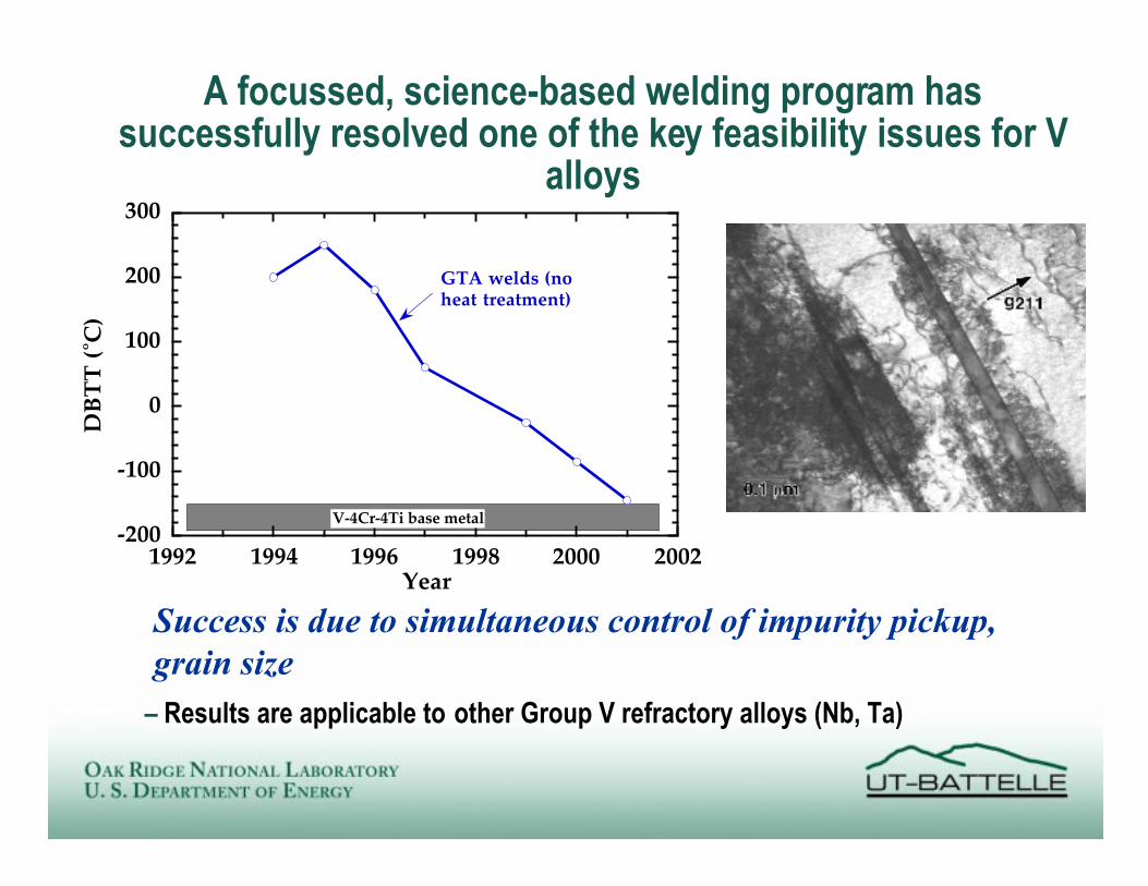
A focussed, science-based welding program hassuccessfully resolved one of the key feasibility issues for V
alloys
Ð Results are applicable to other Group V refractory alloys (Nb, Ta)
-200
-100
0
100
200
300
1992 1994 1996 1998 2000 2002
DB
TT
(ûC
)
Year
V-4Cr-4Ti base metal
GTA welds (no heat treatment)
Fi gure 3 Transm i ssi on el ect r onmicr og raph showin g tw i ns i n wel d GTA 1 7f ollow i ng r em oval o f hydrogen.
Success is due to simultaneous control of impurity pickup,grain size

Dose (dpa)0.1 0.2 0.30
50
100
150
200
250
300
∆σ 0.0
5(M
Pa )
φc=158o
φc=165o
φc=170o
Experiment
OFHC-Cu
Successful Applications in Fusion MaterialScience (2) Quantitative predictions of hardening with only oneadjustable parameter
Measurements at PNNL& RISO
Simulations at UCLA.

Dislocation Dynamics (DD) is a new computer simulationmethod developed at UCLA for modeling fundamentalmicroscopic mechanical properties
0
2
4
[01
0 ](µ
m )
0
2
4
[01
0 ](µ
m )
024
[001 ]
(µm )
024
[001 ]
(µm )
0 2 4
[100] (µm)
0 2 4
[100] (µm)
024
[ 00 1]
( µm)
024
[001 ]
(µm )
0 2 4
[100] (µm)
0 2 4
[100] (µm)
0
2
4
[01
0 ](µ
m )
X
Y
Z
0
2
4
[010] (µ m)
0
2
4
[001
](µ
m)
0
2
4
[1 00] (µ
m)
0
2
4[ 00 1
]( µ
m)
0
2
4[1 00](µ
m)
0
2
4[01
0] (µ m)
XY
Z
Frame 001 01 Jun 2000Frame 001 01 Jun 2000
TEM-Slice
0
2
4[01 0] (µ
m)
0
2
4[ 00 1]
( µm)
0
2
4
[100] (µ m)
0
2
4
[001 ]
(µm )
0
2
4[100] (µ m)
0
2
4
[01 0] (µ
m)
Y
X
Z
Broad Objectives of DD:
1. Understand fundamental deformation mechanisms
2. Provide a physical basis for plasticity
3. Determine stress-strain behavior without assumptions.
4. Design new ultra-strong and super-ductile materials.
(1) N. M. Ghoniem, L. Sun, Phys. Rev. B,60(1): 128-140 (1999).
(2) N.M. Ghoniem, S.- H. Tong, and L. Z.Sun Phys. Rev. B, 61(1): 913-927 (2000).

Colloidal metal nanoclusters can be created in MgAl2O4
Energy loss (eV)
Inte
nsity
(co
unts
)
15 2510
PEELS spectrum for implanted MgAl2O4
Energy-filtered TEM used to quantify colloid distribution
Matrix plasmon peak
colloid peak

Advanced Analytical Electron Microscopy Techniquesare being used to Examine Precipitates in V alloys
Dark Field STEM ImageDark Field STEM Image
20 nm20 nm
0200400600800
10001200
0 1 2 3 4 5 6 7 8
Titanium K αChromium K β
Inte
nsi
ty
Position (nm)
Enriched 3X
Solute Segregation Was Detected in V-4Cr-4Ti FollowingNeutron Irradiation to 0.5 dpa at Elevated Temperatures
Analytical microscopyreveals Ti-rich precipitateswith Fm3m space group(Baker-Nutting precipitate-matrixorientation)


![Materials Science & Engineering A - Illinoishtml.mechse.illinois.edu/files/imported/185.20130226.512d07e... · reaction and the strain magnitudes across transmitting GBs [26–32]](https://img.pdfslide.us/doc/110x75/5a79f91a7f8b9adf778b989a/materials-science-engineering-a-and-the-strain-magnitudes-across-transmitting.jpg)