Embed Size (px)
Citation preview
Extended Finite Element Method for Fretting
Fatigue Crack Propagation
E. Giner a,∗, N. Sukumar b, F.D. Denia a, F.J. Fuenmayor a
aDepartamento de Ingenierıa Mecanica y de Materiales
Universidad Politecnica de Valencia, Camino de Vera, 46022 Valencia, Spain.
bDepartment of Civil and Environmental Engineering
University of California, One Shields Avenue, Davis, CA 95616, USA.
Abstract
In this paper, the extended finite element method (X-FEM) is considered for the
analysis of fretting fatigue problems. A two-dimensional implementation of the X-
FEM is carried out within the finite element software ABAQUSTM by means of user
subroutines, and crack propagation in fretting fatigue problems is investigated. On
utilizing the non-linear contact capabilities of this code, the numerical technique is
applied to a specimen-indenter model. The use of the X-FEM facilitates very accu-
rate stress intensity factor computations on relatively coarse meshes, and further-
more, no remeshing is required for crack growth simulations. The implementation
is applied to complete and incomplete contact fretting problems. A study of crack
growth is conducted for several bulk loads applied to the specimen, and the influ-
ence of the initial crack angle is ascertained. The numerical simulations reveal the
merits of applying the X-FEM to fretting fatigue problems.
Key words: fretting fatigue; crack propagation; extended finite element method;
frictional contact.
∗ Corresponding author. Tel.: +34-96-3877621; fax: +34-96-3877629.
Email address: [email protected] (E. Giner).
Preprint submitted to International Journal of Solids and Structures29 April 2008

1 INTRODUCTION
Problems in fretting fatigue are characterized by the presence of two or more
contacting bodies, subjected to relative displacements of small amplitude. Un-
der these conditions, the stresses exhibit steep gradients in the vicinity of the
contact zone. The combination of such a high stress gradient with the cyclic na-
ture of the loading leads to the nucleation of small cracks that often propagate
until the eventual failure of the component (hence the term fretting fatigue).
In practice, two different stages are distinguished during this process: crack
nucleation and crack propagation.
In fretting fatigue, nucleation processes are usually relatively fast, due to the
strong tractions on the contacting surfaces. Hence, under these circumstances,
most of the component life is spent in the propagation stage (Sheikh et al.,
1994; Adibnazari and Hoeppner, 1994; Hattori et al., 2003). Thus a fracture
mechanics approach is usually considered to be appropriate to estimate fret-
ting fatigue propagation life (Faanes and Fernando, 1994; Faanes, 1995; Hills
and Nowell, 1994). In this study, the nucleation or initiation stage is not con-
sidered and a fully-formed crack is assumed. Its size will be such that the
surrounding material is assumed to be homogeneous and isotropic, i.e. the
crack length is greater than several material grains (Hills and Nowell, 1994;
Dai et al., 1994).
The propagation stage in a fretting fatigue problem is substantially different
from that of plain fatigue during the phase in which the crack length is less
than the characteristic dimension of the contact zone (Hills and Nowell, 1994;
Dai et al., 1994). In such a situation, it is essential to account for the effect of
2
the contact stress field on the crack and vice versa (contact-crack interaction).
It is especially important to estimate realistic values of the stress intensity
factors (SIFs) and as a consequence, numerical modelling often becomes a
necessity (for example, using the finite element method, FEM).
Due to the intrinsic complexity of modelling fretting fatigue, simplifications
are often introduced. Several authors have studied the propagation stage in
two dimensions. Faanes and Harkegard (1994) calculated KI analytically by
applying equivalent contact tractions and Green’s functions. They assumed
either straight cracks growing in a normal direction to the contact surface
or inclined cracks (Faanes, 1995). Kimura and Sato (2003) used a similar
approach extended to inclined mixed-mode cracks. Sheikh et al. (1994) used
a FE model of the classic fretting bridge and studied the SIFs for several
crack lengths and different crack angles with respect to the contact surface.
Mutoh et al. (2003) presented one of the most comprehensive experimental
and numerical studies on crack propagation for a fretting bridge configuration.
Their FE model included the contact influence, with the crack located at the
end of the contact zone. They considered several crack propagation increments
to simulate the crack growth path and applied the estimated values of the
SIFs to compute the fretting fatigue life. General strategies for predicting the
crack growth path in LEFM can be found in the works of Sumi (1985) and
Rubinstein (1991).
As opposed to earlier FE approaches, in recent years the extended finite ele-
ment method (X-FEM) (Moes et al., 1999) has proven to be a very efficient
tool for the numerical modelling of cracks in LEFM. In this study, the method
is applied to 2D crack analysis under fretting conditions. In comparison to the
standard finite element method, the X-FEM provides significant benefits in
3
the numerical modelling of crack propagation. The main advantages are that
the finite element mesh need not to conform to the crack boundaries (crack
faces) to account for the geometric discontinuity, and furthermore, mesh re-
generation is not needed in crack growth simulations. Therefore, only a single
mesh, which is often easily generated, can be used for any crack length and
orientation. The X-FEM is based on the introduction of additional degrees
of freedom (dofs), which are associated with the nodes of the elements inter-
sected by the crack geometry. These extra dofs in combination with special
functions enable the accurate modelling of the crack.
In this paper, we assume a small initial crack that is located near the con-
tact zone, and crack propagation is studied using the extended finite element
method. The objective is to determine the influence of the contact stress field
on the crack growth path. We assume that the crack is open at the max-
imum bulk load on the specimen, and therefore the contact between crack
faces is not modelled in this work. Several situations are studied, combining
different initial cracks and load combinations. The use of the X-FEM enables
the evaluation of the influence of the contact zone on crack propagation in
a very efficient way. Moreover, it permits to estimate accurate values of the
SIF along the crack path by combining energetic post-processing techniques,
like the equivalent domain integral form of the J-integral (EDI method) or
the interaction integral. An analogous study using a standard finite element
formulation would be far less accurate and prohibitively costly, because of the
need for mesh regeneration for each crack length and orientation.
4
2 FUNDAMENTALS OF THE X-FEM
In a standard finite element formulation, a crack must conform to the finite
element mesh and remeshing is required to conduct crack propagation simu-
lations. In contrast, in the X-FEM, a crack is modeled via the displacement
approximation—a function that is discontinuous across the crack is added to
the displacement approximation to model the presence of a crack. Therefore,
crack growth can be done without the need for remeshing. This engenders
additional degrees of freedom (dofs) that are tied to the nodes of the elements
intersected by the crack. The displacement approximation for crack modelling
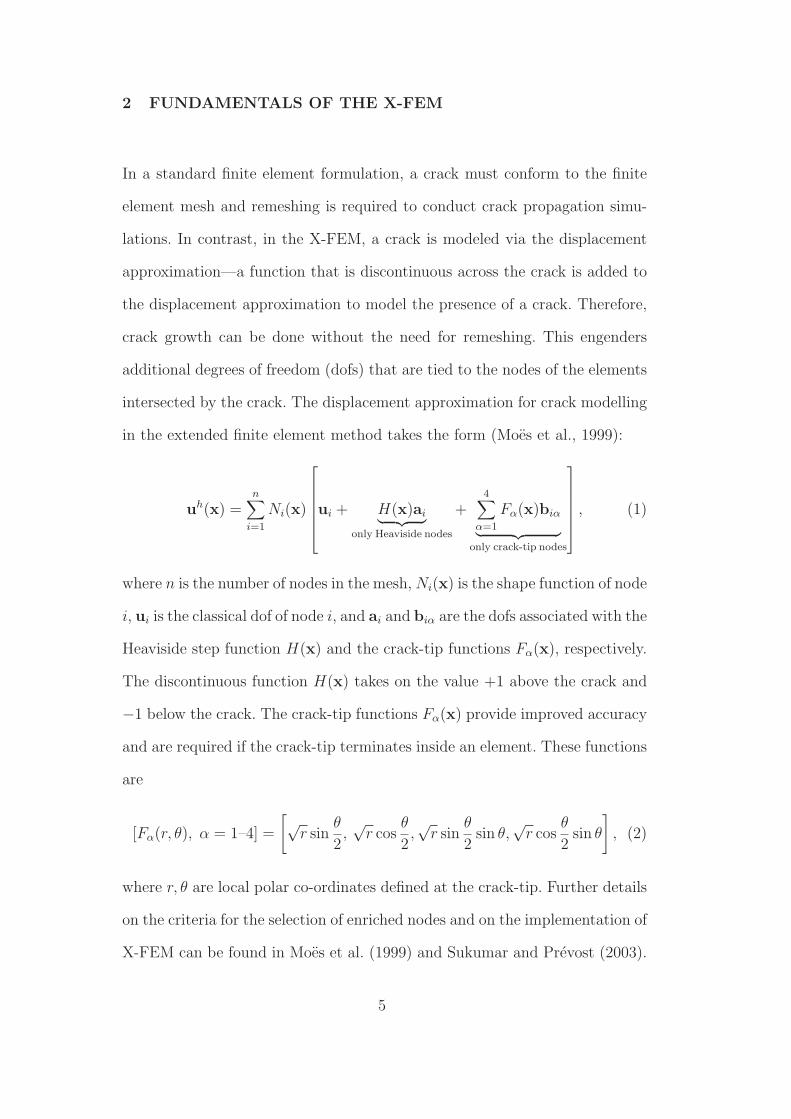
in the extended finite element method takes the form (Moes et al., 1999):
uh(x) =n∑
i=1
Ni(x)
ui + H(x)ai︸ ︷︷ ︸
only Heaviside nodes
+4∑
α=1
Fα(x)biα
︸ ︷︷ ︸
only crack-tip nodes
, (1)
where n is the number of nodes in the mesh, Ni(x) is the shape function of node
i, ui is the classical dof of node i, and ai and biα are the dofs associated with the
Heaviside step function H(x) and the crack-tip functions Fα(x), respectively.
The discontinuous function H(x) takes on the value +1 above the crack and
−1 below the crack. The crack-tip functions Fα(x) provide improved accuracy
and are required if the crack-tip terminates inside an element. These functions
are
[Fα(r, θ), α = 1–4] =
[
√r sin
θ
2,√
r cosθ
2,√
r sinθ
2sin θ,
√r cos
θ
2sin θ
]
, (2)
where r, θ are local polar co-ordinates defined at the crack-tip. Further details
on the criteria for the selection of enriched nodes and on the implementation of
X-FEM can be found in Moes et al. (1999) and Sukumar and Prevost (2003).
5
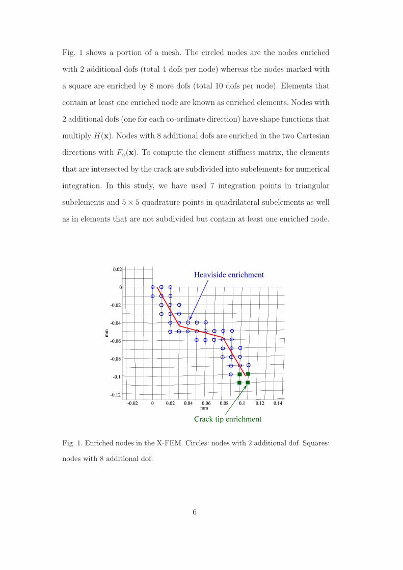
Fig. 1 shows a portion of a mesh. The circled nodes are the nodes enriched
with 2 additional dofs (total 4 dofs per node) whereas the nodes marked with
a square are enriched by 8 more dofs (total 10 dofs per node). Elements that
contain at least one enriched node are known as enriched elements. Nodes with
2 additional dofs (one for each co-ordinate direction) have shape functions that
multiply H(x). Nodes with 8 additional dofs are enriched in the two Cartesian
directions with Fα(x). To compute the element stiffness matrix, the elements
that are intersected by the crack are subdivided into subelements for numerical
integration. In this study, we have used 7 integration points in triangular
subelements and 5× 5 quadrature points in quadrilateral subelements as well
as in elements that are not subdivided but contain at least one enriched node.
Heaviside enrichment
Crack tip enrichment
Fig. 1. Enriched nodes in the X-FEM. Circles: nodes with 2 additional dof. Squares:
nodes with 8 additional dof.
6
3 IMPLEMENTATION AND POST-PROCESSING
In this study, we have implemented the X-FEM in the FE commercial code
ABAQUS (Hibbitt et al., 2004). To our knowledge, this is one of the first
implementations of X-FEM for crack growth simulations within ABAQUS. In
the interest of space, just the main features are mentioned. The analysis pro-
cedure is as follows. After a single mesh generation, geometric computations
based on an exact crack description are carried out to determine the nodes
and elements to be enriched, following the approach described in Moes et al.
(1999). Next, the ABAQUS solver is called to link the user subroutines that
incorporate the X-FEM. The SIFs are then extracted using post-processing
techniques and a crack propagation increment is computed. This increment is
added to the existing crack geometry and the analysis procedure is repeated.
The ABAQUS user-element capability has been used to formulate the enriched
elements. The user-element enables the definition of elements with several dofs
per node. ABAQUS capabilities are limited insofar as user-elements can not
be directly used as part of contacting surfaces in contact problems nor can
user-elements be visualized for plotting purposes. We have overcome these
problems using standard 4-node linear elements with very small (negligible)
stiffness connected to the nodes of every enriched element and retaining the
same connectivity. These overlay elements can then be part of the contact
pair surfaces to model the contact problem in ABAQUS. Note that the over-
lay elements of negligible stiffness are added in parallel to the user-elements,
preserving the actual stiffness of the model. As a consequence, displacements
associated with overlay elements are governed by the underlying X-FEM ele-
ments. In addition, this enables the representation of a linearly interpolated
7
deformed shape of the enriched elements.
From Eq. (1), it is clear that the physical displacement at an enriched node i,
uh(xi) is given by the standard dof ui plus the enriched contribution H(xi)ai
or Fα(xi)biα. This implies that the standard dof ui (the ones used by ABAQUS
in its internal contact algorithm or for plotting) do not correspond to the true
displacement computed with the X-FEM. In order to make the dof ui of an
enriched node i be the physical solution of the nodal displacement, the X-FEM
has been implemented according to the following modification of Eq. (1), the
so-called shifted-basis enrichment (Zi and Belytschko , 2003; Ventura et al.,
2003):
uh(x) =n∑
i=1
Ni(x)
ui + [H(x) − H(xi)] ai︸ ︷︷ ︸
only Heaviside nodes
+4∑
α=1
[Fα(x) − Fα(xi)]biα
︸ ︷︷ ︸
only crack-tip nodes
. (3)
The above procedure has proven to be a very good way to combine user-
elements with the contact algorithm capabilities available within ABAQUS.
To extract the SIFs, we use the domain form of the interaction integral (Chen
and Shield, 1977; Yau et al., 1980). The details on the derivation and its
implementation in the X-FEM is available in the literature (Moes et al., 1999;
Sukumar and Prevost, 2003; Huang et al., 2003). For the crack orientation
prediction based on the values of KI and KII, the MTS criterion proposed
by Erdogan and Sih (1963) (maximum tangential stress or hoop stress σθθ) is
used:
θc = arccos
3K2
II +√
K4I + 8K2
I K2II
K2I + 9K2
II
, (4)
where θc is the angle that will follow the crack for each of the crack increments.
θc is measured with respect to a local polar co-ordinate system with its origin
8
at the crack tip and aligned with the direction of the existing crack. The sign
convention is such that θc < 0 when KII > 0 and vice versa. Other criteria
lead to very similar orientation angles for 2D problems (see a recent review
by Richard et al., 2005).
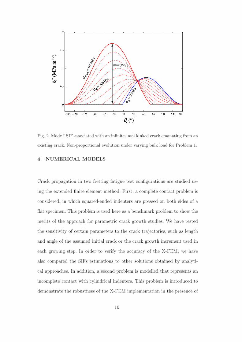
Orientation criteria are well-established for the determination of crack prop-
agation angles under proportional mixed-mode conditions. However, it is re-
ported (Lamacq et al., 1996; Dubourg and Lamacq, 2000) that new criteria or
extensions of these criteria are needed under the strong non-proportional con-
ditions of fretting fatigue loading cycles. Under non-proportional conditions,
the predicted crack angle is different at each step of the loading cycle. It is
claimed that the crack orientation is governed by the direction in which the
amplitude of the mode I opening during the cycle is maximum (not only the
maximum value of the opening). Criteria based on the maximum value of ∆k∗
I
and other modifications seem to yield good estimates under certain conditions
(Lamacq et al., 1996; Dubourg and Lamacq, 2000), where k∗
I is the mode I
SIF associated with an infinitesimal kinked crack emanating from the exist-
ing crack in a given direction (see for example Anderson, 1995). For the two
problems and loading conditions analyzed in this work (which are described
in the next section), we have verified that the criterion based on max(∆k∗
I )
over a cycle yields virtually the same results as the MTS criterion applied at
the instant of maximum bulk loading, as exemplified in Fig. 2. This figure is
computed for a given crack increment of the first problem with a maximum
bulk stress of σB,max = 60 MPa. It can be seen that the maximum effective
range ∆k∗
I is attained at the same angle that maximizes k∗
I for the maximum
bulk loading. Therefore, Eq. (4) has been used at that instant.
9
��� ��� ��� �� �� �� � �� �� �� ��� ��� ������������
)(ºθ
k� (MPa
m� � )
σ
� = 0 M
P a
σ
� ����= 6 0 MP aσ� = 3 0 M P a
max(∆k��)��� ��� ��� �� �� �� � �� �� �� ��� ��� �������
�����
)(ºθ
k� (MPa
m� � )
σ
� = 0 M
P a
σ
� ����= 6 0 MP aσ� = 3 0 M P a
max(∆k��)
Fig. 2. Mode I SIF associated with an infinitesimal kinked crack emanating from an
existing crack. Non-proportional evolution under varying bulk load for Problem 1.
4 NUMERICAL MODELS
Crack propagation in two fretting fatigue test configurations are studied us-
ing the extended finite element method. First, a complete contact problem is
considered, in which squared-ended indenters are pressed on both sides of a
flat specimen. This problem is used here as a benchmark problem to show the
merits of the approach for parametric crack growth studies. We have tested
the sensitivity of certain parameters to the crack trajectories, such as length
and angle of the assumed initial crack or the crack growth increment used in
each growing step. In order to verify the accuracy of the X-FEM, we have
also compared the SIFs estimations to other solutions obtained by analyti-
cal approaches. In addition, a second problem is modelled that represents an
incomplete contact with cylindrical indenters. This problem is introduced to
demonstrate the robustness of the X-FEM implementation in the presence of
10
relatively large sliding zones.
B(t)σ
l
h
c2 B
xy
σ (t)w
a0
σP
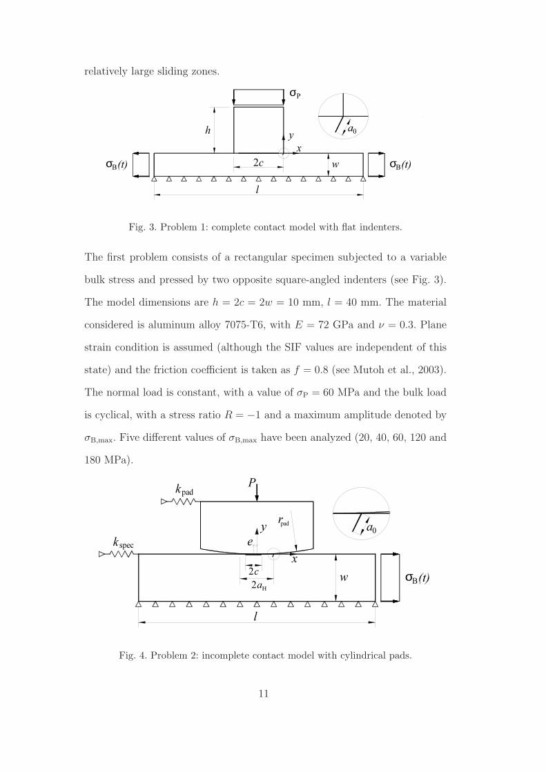
Fig. 3. Problem 1: complete contact model with flat indenters.
The first problem consists of a rectangular specimen subjected to a variable
bulk stress and pressed by two opposite square-angled indenters (see Fig. 3).
The model dimensions are h = 2c = 2w = 10 mm, l = 40 mm. The material
considered is aluminum alloy 7075-T6, with E = 72 GPa and ν = 0.3. Plane
strain condition is assumed (although the SIF values are independent of this
state) and the friction coefficient is taken as f = 0.8 (see Mutoh et al., 2003).
The normal load is constant, with a value of σP = 60 MPa and the bulk load
is cyclical, with a stress ratio R = −1 and a maximum amplitude denoted by
σB,max. Five different values of σB,max have been analyzed (20, 40, 60, 120 and
180 MPa).
k
2a
l
H
spec
c2
ey
(t)Bσw
rpad
x
a0
Pkpad
Fig. 4. Problem 2: incomplete contact model with cylindrical pads.
11
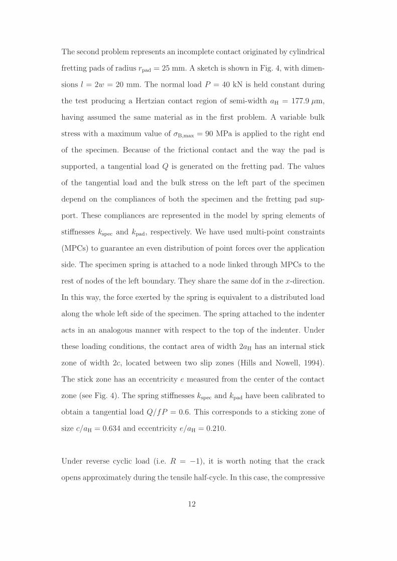
The second problem represents an incomplete contact originated by cylindrical
fretting pads of radius rpad = 25 mm. A sketch is shown in Fig. 4, with dimen-
sions l = 2w = 20 mm. The normal load P = 40 kN is held constant during
the test producing a Hertzian contact region of semi-width aH = 177.9 µm,
having assumed the same material as in the first problem. A variable bulk
stress with a maximum value of σB,max = 90 MPa is applied to the right end
of the specimen. Because of the frictional contact and the way the pad is
supported, a tangential load Q is generated on the fretting pad. The values
of the tangential load and the bulk stress on the left part of the specimen
depend on the compliances of both the specimen and the fretting pad sup-
port. These compliances are represented in the model by spring elements of
stiffnesses kspec and kpad, respectively. We have used multi-point constraints
(MPCs) to guarantee an even distribution of point forces over the application
side. The specimen spring is attached to a node linked through MPCs to the
rest of nodes of the left boundary. They share the same dof in the x-direction.
In this way, the force exerted by the spring is equivalent to a distributed load
along the whole left side of the specimen. The spring attached to the indenter
acts in an analogous manner with respect to the top of the indenter. Under
these loading conditions, the contact area of width 2aH has an internal stick
zone of width 2c, located between two slip zones (Hills and Nowell, 1994).
The stick zone has an eccentricity e measured from the center of the contact
zone (see Fig. 4). The spring stiffnesses kspec and kpad have been calibrated to
obtain a tangential load Q/fP = 0.6. This corresponds to a sticking zone of
size c/aH = 0.634 and eccentricity e/aH = 0.210.
Under reverse cyclic load (i.e. R = −1), it is worth noting that the crack
opens approximately during the tensile half-cycle. In this case, the compressive
12
half-cycle does not have an important effect on the crack growth (Faanes
and Fernando, 1994; Faanes, 1995; Hills and Nowell, 1994). Note that the
maximum KI and KII values are obtained when the crack is totally open,
since the tangential slip of crack faces are not hindered by the compressive
stresses acting on crack faces (Faanes, 1995; Hills and Nowell, 1994; Dubourg
and Lamacq, 2000). Under this assumption we have taken ∆K = Kmax.
Both problems are modelled with 4-node bilinear quadrilateral elements. The
minimum element size in this zone is he = 10 µm (see Fig. 1). This element
size enables the modelling of small cracks that are still longer than he. An
alternative X-FEM formulation for modelling short cracks when compared to
the element size can be found in Bellec and Dolbow (2003). At this point, the
question of the suitability of the initial crack length a0 arises. An initial value
of a0 = 50 µm has been assumed. This size is of the order of several grains for
this material, a necessary condition for the applicability of the LEFM. The
initial crack size has also been estimated using the El Haddad equation (El
Haddad et al., 1979):
a0 =1
π
(∆Kth
σN=106
)2
. (5)
The following values were found in Wittkowsky et al. (2000) for the aluminum
alloy 7075-T6: plain fatigue limit (in terms of stress amplitude) σN=106 =
214 MPa and threshold value ∆Kth = 2.2MPa m1/2 (both for R = −1). Using
Eq. (5), the estimation a0 = 33.6 µm is obtained, which is in good agreement
with the grain size perpendicular to the surface of 35µm reported by Navarro
et al. (2003), measured according to ASTM Standards. Therefore the value
a0 = 50 µm is considered acceptable.
The friction model assumed for the contact zone is a Coulomb model and
13
the ABAQUS contact formulation based on Lagrange multipliers is used. The
Lagrange multiplier formulation enables the exact modelling of sticking con-
tact conditions, in contrast to contact formulations based on penalty methods
(these require a certain amount of slip, the so-called elastic slip dependent on
the penalty constant, to develop a sticking frictional shear traction). The ex-
act modelling of sticking conditions is an important issue in fretting problems
(Goh et al., 2003), to resolve the stick/slip behaviour along the interface.
5 NUMERICAL RESULTS AND DISCUSSION
5.1 Problem 1: Complete contact problem
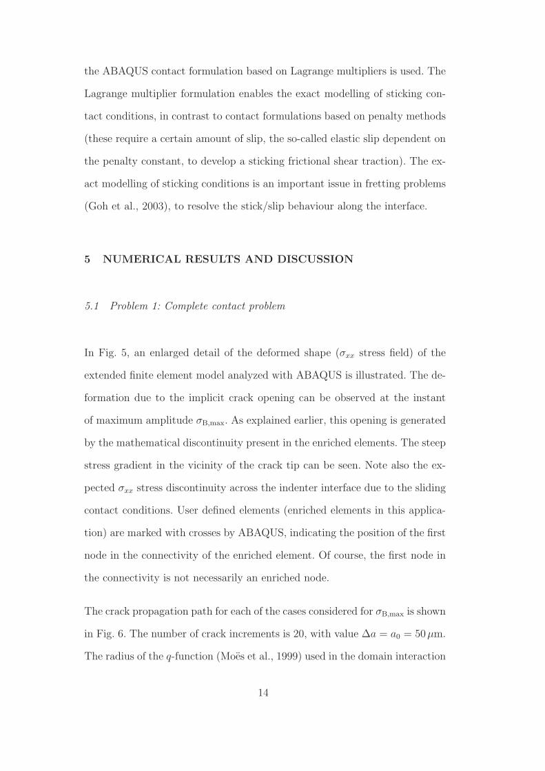
In Fig. 5, an enlarged detail of the deformed shape (σxx stress field) of the
extended finite element model analyzed with ABAQUS is illustrated. The de-
formation due to the implicit crack opening can be observed at the instant
of maximum amplitude σB,max. As explained earlier, this opening is generated
by the mathematical discontinuity present in the enriched elements. The steep
stress gradient in the vicinity of the crack tip can be seen. Note also the ex-
pected σxx stress discontinuity across the indenter interface due to the sliding
contact conditions. User defined elements (enriched elements in this applica-
tion) are marked with crosses by ABAQUS, indicating the position of the first
node in the connectivity of the enriched element. Of course, the first node in
the connectivity is not necessarily an enriched node.
The crack propagation path for each of the cases considered for σB,max is shown
in Fig. 6. The number of crack increments is 20, with value ∆a = a0 = 50µm.
The radius of the q-function (Moes et al., 1999) used in the domain interaction
14
(Ave. Crit.: 75%)S, S11
-1.753e+02-1.003e+02-2.524e+01+4.979e+01+1.248e+02+1.998e+02+2.749e+02+3.499e+02+4.249e+02+4.999e+02+5.750e+02+6.500e+02+1.061e+03
Step: Step-3, Step-3: 2nd half: Increase to the rightIncrement 2: Step Time = 1.000Primary Var: S, S11Deformed Var: U Deformation Scale Factor: +8.000e+00
Job name: Pr1PBODB: grXFEM.odb ABAQUS/STANDARD Version 6.5-1 Sat Apr 26 18:01:04 Hora estÆndar romance 2008
1
2
3
Fig. 5. Enlarged view of the deformed shape for the σxx stress field at the instant
when σB(t) is maximum. Scale factor: 8x.
integral has been taken as rq = 40µm (the minimum element size in this zone is
he = 10 µm). Like the initial length a0, the initial crack orientation θc,0 must
also be defined. In principle, this value can be inferred from experimental
information found in the literature (Adibnazari and Hoeppner, 1994; Mutoh
et al., 2003). The application of certain critical plane methods to estimate the
angle of initiating cracks could also be used (Lamacq et al., 1997). For all cases
of Fig. 6, the initial angle θc,0 is 60o with respect to the free surface of the
specimen. For larger values of σB,max, it can be observed that the influence of
the contact zone due to σP is less significant and the crack tends to grow in a
direction normal to the bulk load σB.
For low bulk loads σB,max, it can be noticed that there is an abrupt change of
direction departing from the initial crack angle θc,0 = 60o. Hence, it is indica-
tive that the true initial angle for those load conditions is different from the
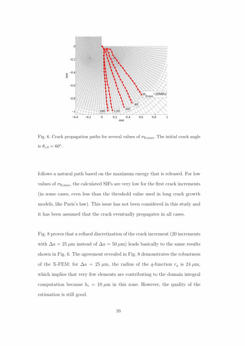
one assumed a priori. The effect of the assumed initial crack angle θc,0 is stud-
ied in Fig. 7. The results reveal that the value of θc,0 does not strongly affect
the orientation after a few crack increments, because the crack propagation
15
−0.4 −0.2 0 0.2 0.4 0.6 0.8 1
−1
−0.8
−0.6
−0.4
−0.2
0
mm
mm
σB,max
=20MPa
4060
120180
Fig. 6. Crack propagation paths for several values of σB,max. The initial crack angle
is θc,0 = 60o.
follows a natural path based on the maximum energy that is released. For low
values of σB,max, the calculated SIFs are very low for the first crack increments
(in some cases, even less than the threshold value used in long crack growth
models, like Paris’s law). This issue has not been considered in this study and
it has been assumed that the crack eventually propagates in all cases.
Fig. 8 proves that a refined discretization of the crack increment (20 increments
with ∆a = 25 µm instead of ∆a = 50 µm) leads basically to the same results
shown in Fig. 6. The agreement revealed in Fig. 8 demonstrates the robustness
of the X-FEM: for ∆a = 25 µm, the radius of the q-function rq is 24 µm,
which implies that very few elements are contributing to the domain integral
computation because he = 10 µm in this zone. However, the quality of the
estimation is still good.
16
−0.2 −0.1 0 0.1 0.2 0.3 0.4
−0.4
−0.35
−0.3
−0.25
−0.2
−0.15
−0.1
−0.05
0
0.05
mm
mm
θc,0
=30º
60º90º120º
σB,max
=60MPa
Fig. 7. Effect of the initial crack angle θc,0 on the propagation path. Load case
σB,max = 60MPa.
−0.2 −0.1 0 0.1 0.2 0.3 0.4 0.5
−0.5
−0.4
−0.3
−0.2
−0.1
0
0.1
mm
mm
σB,max
=60MPa
σB,max
=120MPa
∆a=50µm∆a=25µm
Fig. 8. Effect of the crack increment size ∆a = 25µm and 50µm on the propagation
path. The initial crack is the same in both cases.
5.2 SIF calculations for Problem 1 (complete contact problem)
In order to estimate the orientation angle θc using Eq. (4), all previous analyses
need the computation of KI and KII for each crack growth increment. Since
17

the SIF extraction with the interaction integral is based on the numerical
solution provided by the X-FEM, it is convenient to assess the quality of the
SIF computation, which is obviously affected by the discretization error (like
in a standard FE formulation). In this subsection, we compare some SIFs
calculations using the presented approach with other analytical solutions of
reference for certain configurations.
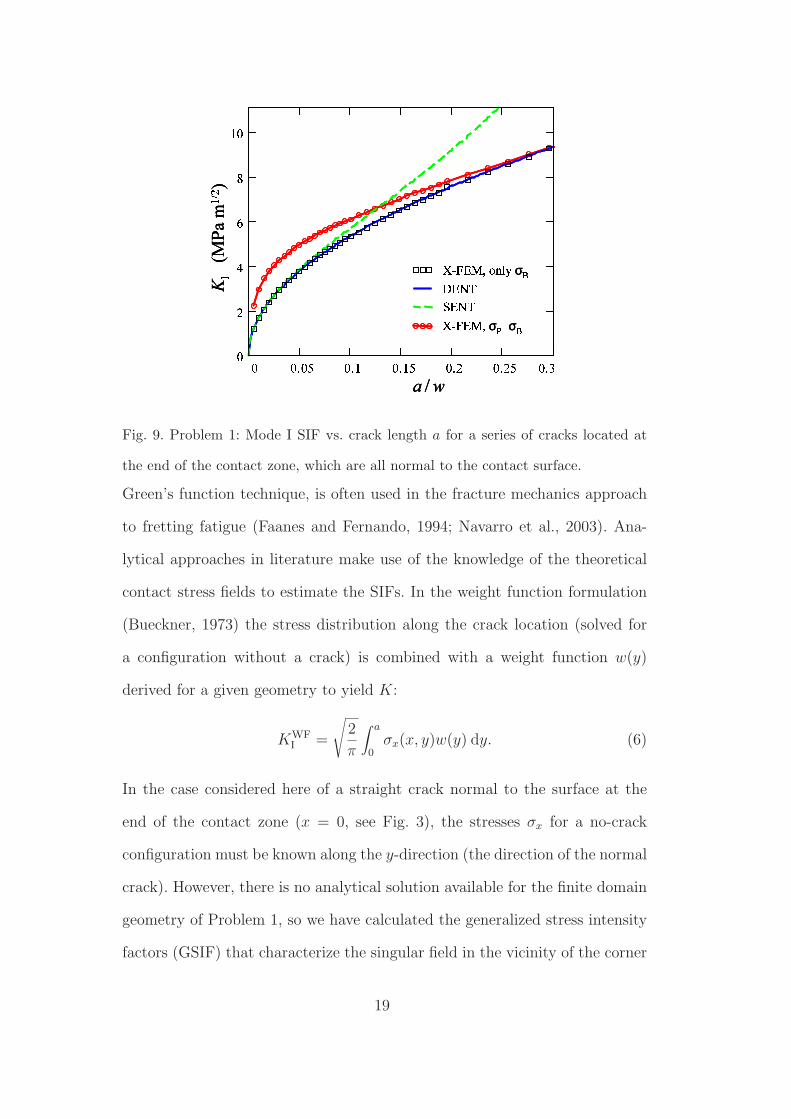
Fig. 9 shows the value of KI vs. the crack length a for a crack located at
the end of the contact zone. In order to make feasible the comparison with
reference solutions, the crack is enforced to be normal to the contact surface
(i.e. no crack deviation is allowed). One of the plotted series of results has
been calculated with only bulk load on the specimen and no contact pressure
on the indenters. The corresponding SIFs agree very well with the analytical
approximation given in Tada et al. (1985) for a double edge crack in a strip of
finite width in tension (DENT). As expected, the approximation with a single
edge crack solution (SENT) is only valid for short cracks (less than 7% of the
half thickness of the specimen w). The SIF solution for the fretting fatigue
loading condition (bulk load combined with the normal load on the indenter)
is also plotted in Fig. 9. The effect of the contact load is to increase the severity
of the crack, yielding larger values of KI than for a plain fatigue situation. This
effect agrees well with the experimental evidence reported in the literature (see
for example Hills and Nowell, 1994), as fretting tends to induce faster crack
growth rates than plain fatigue during the early propagation stages. As the
crack grows, the contact influence decreases and the behaviour approaches
that of plain fatigue.
This latter series of fretting fatigue results has been also estimated in this
work using weight functions, an analytical procedure that, together with the
18
������σ��σ ! !"!# !"$ !"$# !"% !"%# !"&!%
'()$!
wa /
K
*(MPa m+,- )
.�/0������ 1234 σ 5�/0������σ��σ ������σ��σ ! !"!# !"$ !"$# !"% !"%# !"&!%
'()$!
wa /
K
*(MPa m+,- )
.�/0������ 1234 σ 5�/0! !"!# !"$ !"$# !"% !"%# !"&!%'()$!
wa /
K
*(MPa m+,- )
.�/0������ 1234 σ 5�/0Fig. 9. Problem 1: Mode I SIF vs. crack length a for a series of cracks located at
the end of the contact zone, which are all normal to the contact surface.
Green’s function technique, is often used in the fracture mechanics approach
to fretting fatigue (Faanes and Fernando, 1994; Navarro et al., 2003). Ana-
lytical approaches in literature make use of the knowledge of the theoretical
contact stress fields to estimate the SIFs. In the weight function formulation
(Bueckner, 1973) the stress distribution along the crack location (solved for
a configuration without a crack) is combined with a weight function w(y)
derived for a given geometry to yield K:
KWFI =
√
2
π
∫ a
0σx(x, y)w(y) dy. (6)
In the case considered here of a straight crack normal to the surface at the
end of the contact zone (x = 0, see Fig. 3), the stresses σx for a no-crack
configuration must be known along the y-direction (the direction of the normal
crack). However, there is no analytical solution available for the finite domain
geometry of Problem 1, so we have calculated the generalized stress intensity
factors (GSIF) that characterize the singular field in the vicinity of the corner
19
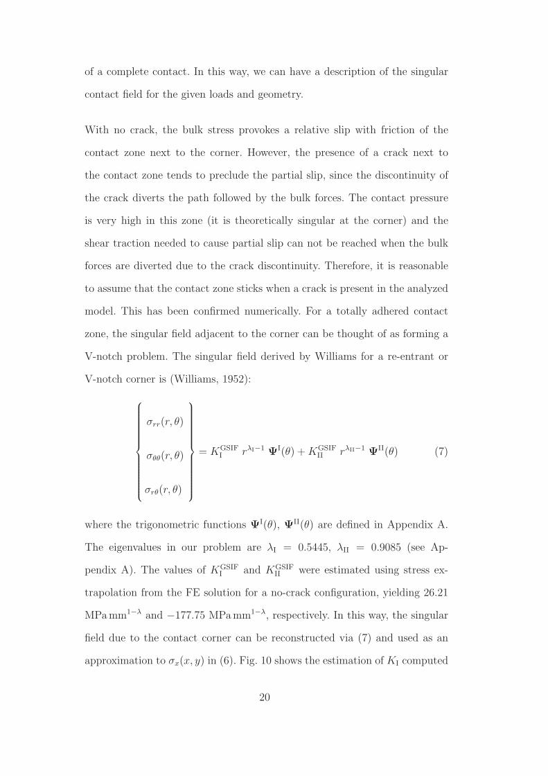
of a complete contact. In this way, we can have a description of the singular
contact field for the given loads and geometry.
With no crack, the bulk stress provokes a relative slip with friction of the
contact zone next to the corner. However, the presence of a crack next to
the contact zone tends to preclude the partial slip, since the discontinuity of
the crack diverts the path followed by the bulk forces. The contact pressure
is very high in this zone (it is theoretically singular at the corner) and the
shear traction needed to cause partial slip can not be reached when the bulk
forces are diverted due to the crack discontinuity. Therefore, it is reasonable
to assume that the contact zone sticks when a crack is present in the analyzed
model. This has been confirmed numerically. For a totally adhered contact
zone, the singular field adjacent to the corner can be thought of as forming a
V-notch problem. The singular field derived by Williams for a re-entrant or
V-notch corner is (Williams, 1952):
σrr(r, θ)
σθθ(r, θ)
σrθ(r, θ)
= KGSIFI rλI−1 ΨI(θ) + KGSIF
II rλII−1 ΨII(θ) (7)
where the trigonometric functions ΨI(θ), ΨII(θ) are defined in Appendix A.
The eigenvalues in our problem are λI = 0.5445, λII = 0.9085 (see Ap-
pendix A). The values of KGSIFI and KGSIF
II were estimated using stress ex-
trapolation from the FE solution for a no-crack configuration, yielding 26.21
MPa mm1−λ and −177.75 MPa mm1−λ, respectively. In this way, the singular
field due to the contact corner can be reconstructed via (7) and used as an
approximation to σx(x, y) in (6). Fig. 10 shows the estimation of KI computed
20
using (6). It can be seen that the agreement with the extended finite element
solution is good for very small cracks, where the singular field dominates. Due
to the small crack size, this agreement is attained with both the single-edge
crack weight function (SENT) given by Bueckner (1973) and with the more
appropriate double-edge crack weight function (DENT) given by Fett et al.
(1988). Obviously, the solution for a DENT weight function tends to approach
the extended finite element solution for longer cracks.
wa /6 6768 679 6798 67: 67:8 67;6:
<=>96
?@ABCDσEFσGHA IBJKLBJKHA LBJK
wa /6 6768 679 6798 67: 67:8 67;6:
<=>96
?@ABCDσEFσGHA IBJKLBJKHA LBJK6 6768 679 6798 67: 67:8 67;6:
<=>96
?@ABCDσEFσGHA IBJKLBJKHA LBJK
Fig. 10. Problem 1: Mode I SIF vs. crack length a for a series of cracks located at the
end of the contact zone, which are all normal to the contact surface. Comparison
with analytical computations using weight functions.
From the above analysis for normal cracks, we conclude that the X-FEM
yields good estimations of the SIF. We must point out that the extended
finite element method is not restricted to normal straight cracks, but allows
the analysis of more complex crack geometries, including inclined and kinked
geometries. In addition, since the X-FEM inherits the main advantages of the
FEM, the influence of nearby boundaries is also considered, which can be more
21
involved in other methods, such as the distributed dislocation technique (Hills
and Nowell, 1994).
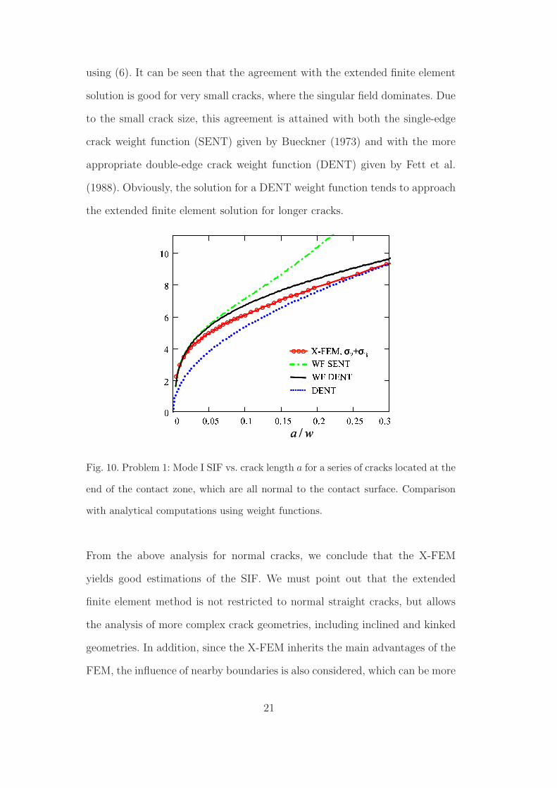
Finally, in Fig. 11 we represent the numerical value of KI and KII as well as
the orientation angle calculated with Eq. (4) vs. crack length (measured as the
addition of the crack growth increments) for the case σB,max = 120MPa shown
in Fig. 6. It can be observed that the propagation path tends to minimize the
value of KII and that the sign of KII is opposite to the θc sign, according to
the customary sign convention. As expected, the values of KI increase with
the crack length and can be identified with ∆KI.
0 200 400 600 800 1000−2
0 2 4 6 8
10
12
Crack length (µm)
KI ,
KII
(MP
a m1/
2 )
KI
KII
θc
θc (º)
σB,max
=120 MPa
−40−200+20+40
Fig. 11. Problem 1: SIFs values and orientation angle for the case σB,max = 120MPa
shown in Fig. 6.
5.3 Problem 2: Incomplete contact problem
The approach presented in this study can be applied to other geometries and
contact conditions. We introduce now the incomplete contact problem to show
22
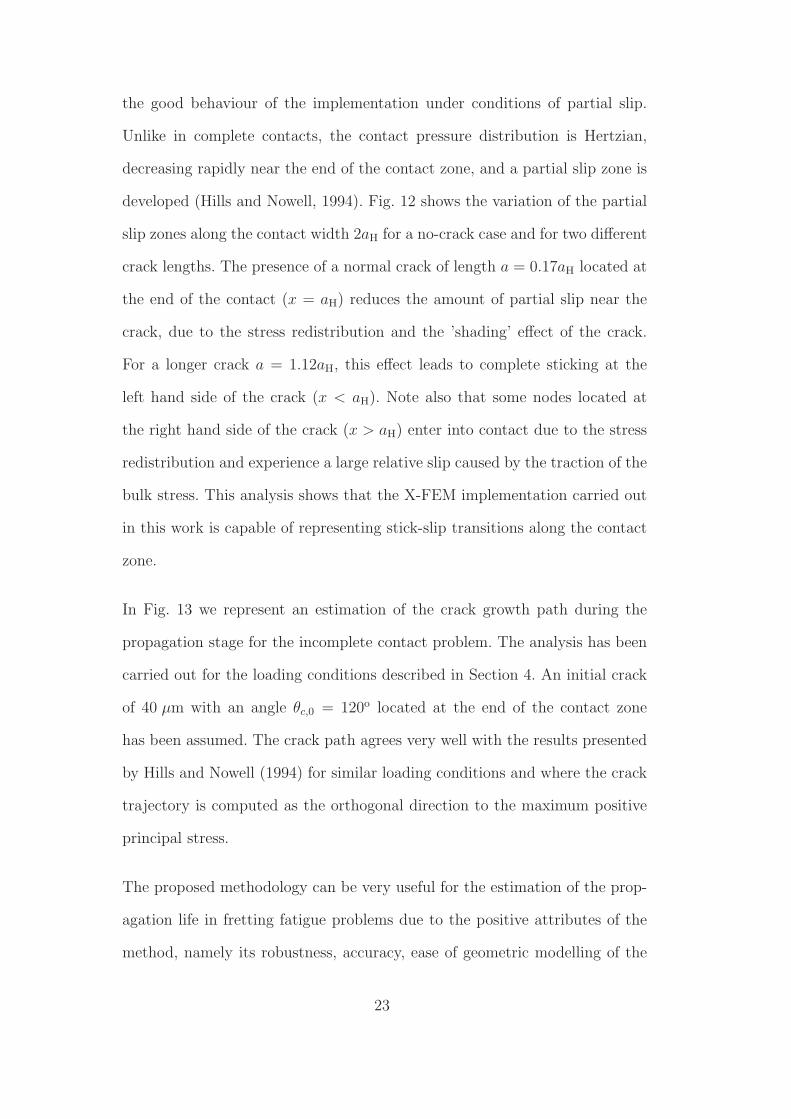
the good behaviour of the implementation under conditions of partial slip.
Unlike in complete contacts, the contact pressure distribution is Hertzian,
decreasing rapidly near the end of the contact zone, and a partial slip zone is
developed (Hills and Nowell, 1994). Fig. 12 shows the variation of the partial
slip zones along the contact width 2aH for a no-crack case and for two different
crack lengths. The presence of a normal crack of length a = 0.17aH located at
the end of the contact (x = aH) reduces the amount of partial slip near the
crack, due to the stress redistribution and the ’shading’ effect of the crack.
For a longer crack a = 1.12aH, this effect leads to complete sticking at the
left hand side of the crack (x < aH). Note also that some nodes located at
the right hand side of the crack (x > aH) enter into contact due to the stress
redistribution and experience a large relative slip caused by the traction of the
bulk stress. This analysis shows that the X-FEM implementation carried out
in this work is capable of representing stick-slip transitions along the contact
zone.
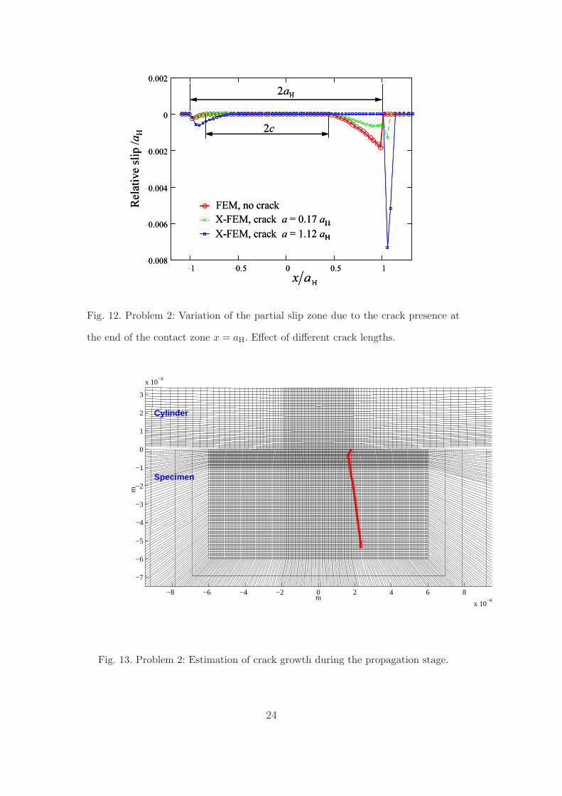
In Fig. 13 we represent an estimation of the crack growth path during the
propagation stage for the incomplete contact problem. The analysis has been
carried out for the loading conditions described in Section 4. An initial crack
of 40 µm with an angle θc,0 = 120o located at the end of the contact zone
has been assumed. The crack path agrees very well with the results presented
by Hills and Nowell (1994) for similar loading conditions and where the crack
trajectory is computed as the orthogonal direction to the maximum positive
principal stress.
The proposed methodology can be very useful for the estimation of the prop-
agation life in fretting fatigue problems due to the positive attributes of the
method, namely its robustness, accuracy, ease of geometric modelling of the
23
Max
Relat
ive sli
p /aH
N2a
c2
1 0.5 0 0.5 10.008
0.006
0.004
0.002
0
0.002
FEM, no crack
X-FEM, crack a = 1.12 aOX-FEM, crack a = 0.17 aOMax
Relat
ive sli
p /aH
N2a
c2
1 0.5 0 0.5 10.008
0.006
0.004
0.002
0
0.002
FEM, no crack
X-FEM, crack a = 1.12 aOX-FEM, crack a = 0.17 aOFig. 12. Problem 2: Variation of the partial slip zone due to the crack presence at
the end of the contact zone x = aH. Effect of different crack lengths.
−8 −6 −4 −2 0 2 4 6 8
x 10−4
−7
−6
−5
−4
−3
−2
−1
0
1
2
3
x 10−4
m
m
Cylinder
Specimen
Fig. 13. Problem 2: Estimation of crack growth during the propagation stage.
24
crack and the inclusion of the contact model with friction. The estimation of
the propagation life in fretting is considered in the literature (Faanes and Fer-
nando, 1994; Faanes, 1995; Mutoh et al., 2003) based on the SIFs calculated
under contact influence. Navarro et al. (2003) compute the SIF using weight
functions during the propagating stage. In general, these studies are based on
simplifications regarding the crack shape and the effects of contact tractions.
Following the approach we have pursued, such simplifications in the numerical
model are circumvented, and more accurate SIFs are realized. This is espe-
cially important when using crack growth laws for estimating propagation lives
that strongly depend on the accuracy of the SIFs.
There are other important issues that have not been addressed in this work,
which deserve further attention, such as the study over complete cycles includ-
ing crack closure effects. To study crack closure effects, X-FEM formulations
that include frictional contact between crack faces (Dolbow et al., 2001; Kim
et al., 2007; Ribeaucourt et al., 2007) are promising.
6 CONCLUSIONS
The combination of the advantages of the X-FEM and the inherent capabil-
ities in ABAQUS for modelling contact problems has lead to a methodology
for the analysis of crack propagation in fretting fatigue problems. The X-
FEM has been implemented in the commercial code ABAQUS by means of
user-element subroutines. The use of X-FEM in fretting fatigue introduces
a number of distinct benefits over existing models that appear in the litera-
ture. The main advantage is that modelling any crack location and orientation
becomes a straightforward task, using an easily generated single mesh. This
25
allows the simulation of crack propagation in a computationally elegant, sim-
ple, and cost-effective manner. In addition, the methodology provides accurate
SIF extractions through energetic methods based on domain integrals. The ac-
curacy attained is much better than with a standard FE formulation due to
the use of crack-tip enrichment functions that adapt much better than the FE
solution to the singular crack-tip fields.
In this paper, the methodology has been applied to complete and incomplete
contact problems. The influence of the bulk load, the effect of the initial crack
angle θc,0 and the crack increment ∆a have been studied, as well as the per-
formance of the implementation under sticking or partial slip conditions. The
proposed methodology is robust and accurate and allows the study of sev-
eral crack configurations. The numerical results demonstrate the merits of the
X-FEM for the estimation of the fretting fatigue life during the propagation
stage.
Acknowledgements
The authors wish to thank Ministerio de Ciencia y Tecnologıa for the sup-
port received in the framework of the project DPI2007-66995-C03-02. The
financial support received from Vicerrectorado de Investigacion, Desarrollo e
Innovacion (Universidad Politecnica de Valencia) and Conselleria d’Empresa,
Universitat i Ciencia (Generalitat Valenciana) through the project GV06/124
is also gratefully acknowledged. This support enabled the research visit of E.
Giner to UC Davis, where parts of this research were accomplished.
26
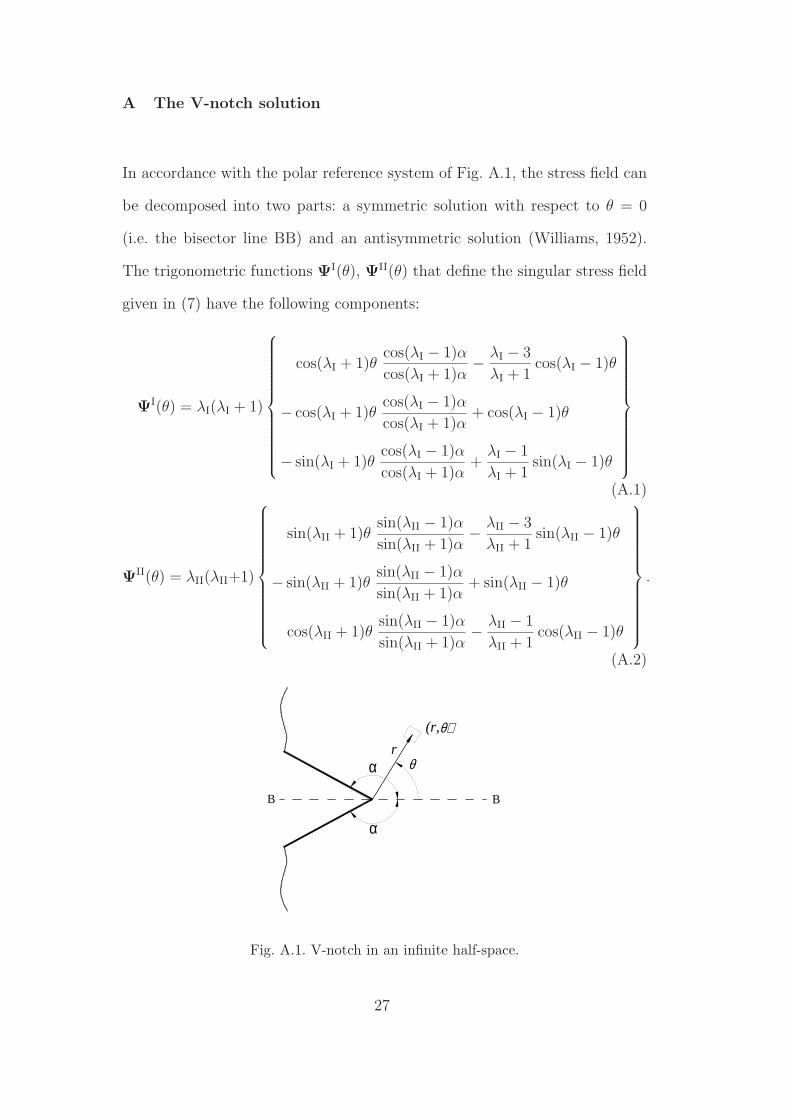
A The V-notch solution
In accordance with the polar reference system of Fig. A.1, the stress field can
be decomposed into two parts: a symmetric solution with respect to θ = 0
(i.e. the bisector line BB) and an antisymmetric solution (Williams, 1952).
The trigonometric functions ΨI(θ), ΨII(θ) that define the singular stress field
given in (7) have the following components:
ΨI(θ) = λI(λI + 1)
cos(λI + 1)θcos(λI − 1)α
cos(λI + 1)α−
λI − 3
λI + 1cos(λI − 1)θ
− cos(λI + 1)θcos(λI − 1)α
cos(λI + 1)α+ cos(λI − 1)θ
− sin(λI + 1)θcos(λI − 1)α
cos(λI + 1)α+
λI − 1
λI + 1sin(λI − 1)θ
(A.1)
ΨII(θ) = λII(λII+1)
sin(λII + 1)θsin(λII − 1)α
sin(λII + 1)α−
λII − 3
λII + 1sin(λII − 1)θ
− sin(λII + 1)θsin(λII − 1)α
sin(λII + 1)α+ sin(λII − 1)θ
cos(λII + 1)θsin(λII − 1)α
sin(λII + 1)α−
λII − 1
λII + 1cos(λII − 1)θ
.
(A.2)
(r,
r
B B
θ
θ)
α
α
Fig. A.1. V-notch in an infinite half-space.
27
In (7) the eigenvalue λI is the lowest positive solution of the so-called charac-
teristic equation for the symmetric solution:
λI sin(2α) + sin(2λIα) = 0 (A.3)
and corresponds to the most singular solution. Analogously, the eigenvalue λII
is the lowest positive solution of the characteristic equation for the antisym-
metric solution:
λII sin(2α) − sin(2λIIα) = 0. (A.4)
References
Adibnazari, S., Hoeppner, D.W., 1994. The role of normal pressure in mod-
elling fretting fatigue. ESIS 18. In: Fretting Fatigue (Edited by R.B. Water-
house and T.C. Lindley). Mechanical Engineering Publications Ltd, London,
pp. 125–133.
Anderson, T.L., 1995. Fracture Mechanics: Fundamentals and Applications.
2nd Ed. CRC Press, Boca Raton.
Bellec, J., Dolbow, J.E., 2003. A note on enrichment functions for modelling
crack nucleation. Communications in Numerical Methods in Engineering 19,
921–932.
Bueckner, H.F., 1973. Field singularities and related integral representations.
In: Mechanics of Fracture 1. Methods of analysis and solutions of crack
problems, ed. G.C. Sih. Noordhoff International Publishing, Leyden, pp.
239–314.
Chen, F.H.K., Shield, R.T., 1977. Conservation laws in elasticity of the J -
integral type. Journal of Applied Mathematics and Physics (ZAMP) 28,
1–22.
28

Dai, D.N., Hills, D.A., Nowell, D., 1994. Stress intensity factors for three-
dimensional fretting fatigue cracks. ESIS 18. In: Fretting Fatigue (Edited by
R.B. Waterhouse and T.C. Lindley). Mechanical Engineering Publications
Ltd, London, pp. 59–71.
Dolbow, J., Moes, N., Belytschko, T., 2001. An extended finite element method
for modeling crack growth with frictional contact. Computer Methods in
Applied Mechanics and Engineering 190 (51-52), 6825–6846.
Dubourg, M.C., Lamacq, V., 2000. Stage II crack propagation direction deter-
mination under fretting fatigue loading: a new approach in accordance with
experimental observations. In: Fretting Fatigue: Current Technology and
Practices. Edited by D.W. Hoeppner, V. Chandrasekaran and C.B. Elliot).
ASTM STP 1367, West Conshohocken, pp. 436–450.
El Haddad, M.H., Topper, T.H., Smith, K.N., 1979. Prediction of non propa-
gating cracks. Engineering Fracture Mechanics 11 (3), 573–584.
Erdogan, F., Sih, G.C., 1963. On the crack extension in plates under plane
loading and transverse shear. Journal of Basic Engineering 85, 519-527.
Faanes, S., 1995. Inclined cracks in fretting fatigue. Engineering Fracture Me-
chanics 52 (1), 71–82.
Faanes, S., Fernando, U.S., 1994. Influence of contact loading on fretting fa-
tigue behaviour. Fatigue and Fracture of Engineering Matererials and Struc-
tures 17 (8), 939–947.
Faanes, S., Harkegard, G., 1994. Simplified stress intensity factors in fretting
fatigue. ESIS 18. In: Fretting Fatigue (Edited by R.B. Waterhouse and T.C.
Lindley). Mechanical Engineering Publications Ltd, pp. London, 73–81.
Fett, T., Stamm, H., Walz, G., 1988. Weight function for finite strip with
double-edge notches. Theoretical and Applied Fracture Mechanics 10, 227–
230.
29

Goh, C.H., Neu, R.W., McDowell, D.L., 2003. Influence of nonhomegeneous
material in fretting fatigue. In: Fretting Fatigue: Advances in Basic Under-
standing and Applications (Edited by S.E. Kinyon, D.W. Hoeppner and Y.
Mutoh). ASTM STP 1425, West Conshohocken, pp. 183–205.
Hattori, T., Nakamura, M., Watanabe, T., 2003. Simulation of fretting fatigue
life by using stress-singularity parameters and fracture mechanics. Tribology
International 36, 87–97.
Hibbitt, Karlsson & Sorensen, Inc., 2004. ABAQUS/Standard User’s Manual,
V. 6.5, Pawtucket, Rhode Island.
Hills, D.A., Nowell, D., 1994. Mechanics of fretting fatigue. Kluwer Academic
Publishers, Dordrecht.
Huang, R., Sukumar, N., Prevost, J.-H., 2003. Modeling quasi-static crack
growth with the extended finite element method. Part II: Numerical appli-
cations. International Journal of Solids and Structures 40 (26), 7539–7552.
Kim, T.Y., Dolbow, J., Laursen, T., 2007. A mortared finite element method
for frictional contact on arbitrary interfaces. Computational Mechanics 39,
223–235.
Kimura, T., Sato, K., 2003. Simplified method to determine contact stress
distribution and stress intensity factors in fretting fatigue. International
Journal of Fatigue 25, 633–640.
Lamacq, V., Dubourg, M.C., Vincent, L., 1996. Crack path prediction un-
der fretting fatigue. A theoretical and experimental approach. Journal of
Tribology 118, 711–720.
Lamacq, V., Dubourg, M.C., Vincent, L., 1997. A theoretical model for the
prediction of initial growth angles and sites of fretting fatigue cracks. Tri-
bology International 30 (6), 391–400.
Moes, N., Dolbow, J., Belytschko, T., 1999. A finite element method for crack
30

growth without remeshing. International Journal for Numerical Methods in
Engineering 46 (1), 131–150.
Mutoh, Y., Xu, J.Q., Kondoh, K., 2003. Observations and analysis of fretting
fatigue crack initiation and propagation. In: Fretting Fatigue: Advances
in Basic Understanding and Applications (Edited by S.E. Kinyon, D.W.
Hoeppner and Y. Mutoh). ASTM STP 1425, West Conshohocken, pp. 61–
75.
Navarro, C., Garcıa, M., Domınguez, J., 2003. A procedure for estimating the
total life in fretting fatigue. Fatigue and Fracture of Engineering Matererials
and Structures 26 (5), 459–468.
Ribeaucourt, R., Baietto-Dubourg, M.-C., Gravouil, A., 2007. A new fatigue
frictional contact crack propagation model with the coupled X-FEM/LATIN
method. Computer Methods in Applied Mechanics and Engineering 196,
3230-3247.
Richard, H.A., Fulland, M., Sander, M., 2005. Theoretical crack path predic-
tion. Fatigue and Fracture of Engineering Matererials and Structures 28,
3-12.
Rubinstein, A.A., 1991. Mechanics of the crack path formation. International
Journal of Fracture 47, 291–305.
Sheikh, M.A., Fernando, U.S., Brown, M.W., Miller, K.J.M., 1994. Elastic
stress intensity factors for fretting cracks using the finite element method.
ESIS 18. In: Fretting Fatigue (Edited by R.B. Waterhouse and T.C. Lind-
ley). Mechanical Engineering Publications Ltd, London, pp. 83–101.
Sukumar, N., Prevost, J.-H., 2003. Modeling quasi-static crack growth with
the extended finite element method. Part I: Computer implementation. In-
ternational Journal of Solids and Structures 40 (26), 7513–7537.
Sumi, Y., 1985. Computational crack path prediction. Theoretical and Applied
31
Fracture Mechanics 4, 149–156.
Tada, H., Paris, P.C., Irwin, G.C., eds., 1985. The stress analysis of cracks
handbook. 2nd. ed. Paris Productions, Inc. St. Louis, Missouri.
Ventura, G., Budyn, E., Belytschko, T., 2003. Vector level sets for description
of propagating cracks in finite elements. International Journal for Numerical
Methods in Engineering 58, 1571–1592.
Williams, M.L., 1952. Stress singularities resulting from various boundary con-
ditions in angular corners of plates in extension. Journal of Applied Mechan-
ics 19, 526–528.
Wittkowsky, B.U., Birch, P.R., Domınguez, J., Suresh, S., 2000. An experi-
mental investigation of fretting fatigue with spherical contact in 7075-T6
aluminum alloy. In: Fretting Fatigue: Current Technology and Practices.
Edited by D.W. Hoeppner, V. Chandrasekaran and C.B. Elliot). ASTM
STP 1367, West Conshohocken, pp. 213–227.
Yau, J.F., Wang, S.S., Corten, H.T., 1980. A mixed-mode crack analysis of
isotropic solids using conservation laws of elasticity. Journal of Applied Me-
chanics 47, 335–341.
Zi, G., Belytschko, T., 2003. New crack-tip elements for XFEM and applica-
tions to cohesive cracks. International Journal for Numerical Methods in
Engineering 57, 2221–2240.
32
FIGURE CAPTIONS
Fig. 1. Enriched nodes in the X-FEM. Circles: nodes with 2 additional dof.
Squares: nodes with 8 additional dof.
Fig. 2. Mode I SIF associated with an infinitesimal kinked crack emanating
from an existing crack. Non-proportional evolution under varying bulk load
for Problem 1.
Fig. 3. Problem 1: complete contact model with flat indenters.
Fig. 4. Problem 2: incomplete contact model with cylindrical pads.
Fig. 5. Enlarged view of the deformed shape for the σxx stress field at the
instant when σB(t) is maximum. Scale factor: 8x.
Fig. 6. Crack propagation paths for several values of σB,max. The initial crack
angle is θc,0 = 60o.
Fig. 7. Effect of the initial crack angle θc,0 on the propagation path. Load
case σB,max = 60MPa.
Fig. 8. Effect of the crack increment size ∆a = 25 µm and 50 µm on the
propagation path. The initial crack is the same in both cases.
Fig. 9. Problem 1: Mode I SIF vs. crack length a for a series of cracks located
at the end of the contact zone, which are all normal to the contact surface.
Fig. 10. Problem 1: Mode I SIF vs. crack length a for a series of cracks located
at the end of the contact zone, which are all normal to the contact surface.
Comparison with analytical computations using weight functions.
33

Fig. 11. Problem 1: SIFs values and orientation angle for the case σB,max =
120MPa shown in Fig. 6.
Fig. 12. Problem 2: Variation of the partial slip zone due to the crack presence
at the end of the contact zone x = aH. Effect of different crack lengths.
Fig. 13. Problem 2: Estimation of crack growth during the propagation stage.
Fig A.1. V-notch in an infinite half-space.
34


![A hybrid XFEM - Phase Field (Xfield) method for crack … · 2016. 11. 10. · A hybrid XFEM - Phase Field (Xfield) method for crack propagation in brittle materials BIANCA GIOVANARDI],](https://img.pdfslide.us/doc/110x75/614a978a12c9616cbc69840e/a-hybrid-xfem-phase-field-xfield-method-for-crack-2016-11-10-a-hybrid-xfem.jpg)


![A hybrid XFEM - Phase Field (Xfield) method for crack ... · A hybrid XFEM - Phase Field (Xfield) method for crack propagation in brittle materials BIANCA GIOVANARDI], ANNA SCOTTI](https://img.pdfslide.us/doc/110x75/5ade1d027f8b9a595f8db44e/a-hybrid-xfem-phase-field-xfield-method-for-crack-hybrid-xfem-phase-field.jpg)


![An XFEM method for modeling geometrically elaborate crack ... · AN XFEM METHOD FOR GEOMETRICALLY ELABORATE CRACK PROPAGATION 3 for holes and inclusions see [24]) and has also been](https://img.pdfslide.us/doc/110x75/5ad9bedd7f8b9a53618bac1b/an-xfem-method-for-modeling-geometrically-elaborate-crack-xfem-method-for-geometrically.jpg)