Embed Size (px)
Citation preview

ETSI TC SMG TDoc SMG 77/97Meeting #21Paris, 10th - 14th February 1997
Source: SMG 2
Title: GSM 03.64 version 1.0.1 Overall Description of the General Packet RadioService (GPRS) Radio Interface Stage 2
Proposed agenda item: 6.2
Presented for: Information

GSM GSM 03.64
TECHNICAL 31st January 1997
SPECIFICATION Version 1.0.1
Source: ETSI TC-SMG Reference:
ICS:
Key words: Digital cellular telecommunications system, Global System for Mobile communications (GSM),General Packet Radio Service (GPRS)
Digital cellular telecommunications system (Phase 2+);General Packet Radio Service (GPRS);
Overall Description of the General Packet Radio Service(GPRS) Radio Interface;
Stage 2;(GSM 03.64)
ETSI
European Telecommunications Standards Institute
ETSI Secretariat
Postal address: F-06921 Sophia Antipolis CEDEX - FRANCEOffice address: 650 Route des Lucioles - Sophia Antipolis - Valbonne - FRANCEX.400: c=fr, a=atlas, p=etsi, s=secretariat - Internet: [email protected]
Tel.: +33 92 94 42 00 - Fax: +33 93 65 47 16
Copyright Notification: No part may be reproduced except as authorized by written permission. The copyright and the foregoingrestriction extend to reproduction in all media.© European Telecommunications Standards Institute 1996. All rights reserved.

Page 2GSM 03.64 version 1.0.1: January 1997
Blank page

Page 3GSM 03.64 version 1.0.1: January 1997
Contents
Foreword....................................................................................................................................................................... 5
1. Scope......................................................................................................................................................................... 7
2. Normative references ................................................................................................................................................ 7
3. Definitions and Abbreviations .................................................................................................................................. 7
4. Packet Data Logical Channels................................................................................................................................... 94.1. General........................................................................................................................................................ 94.2. Packet Common Control Channel (PCCCH) .............................................................................................. 9
4.2.1. Packet Random Access Channel (PRACH) - uplink only....................................................... 94.2.2. Packet Paging Channel (PPCH) - downlink only.................................................................... 94.2.3. Packet Access Grant Channel (PAGCH) - downlink only ...................................................... 9
4.3. Packet Broadcast Control Channel (PBCCH) - downlink only................................................................... 94.4. Packet Traffic Channels.............................................................................................................................. 9
4.4.1. Packet Data Traffic Channel (PDTCH) .................................................................................. 94.4.2. Packet Associated Control Channel (PACCH) ....................................................................... 9
5. Mapping of Packet Data Logical Channels onto Physical Channels ....................................................................... 105.1. General...................................................................................................................................................... 105.2. Packet Data Common Control Channels (PCCCH) .................................................................................. 10
5.2.1. Packet Random Access Channel (PRACH) .......................................................................... 105.2.2. Packet Paging Channel (PPCH)............................................................................................ 105.2.3. Packet Access Grant Channel (PAGCH) .............................................................................. 10
5.3. Packet Broadcast Control Channel (PBCCH)........................................................................................... 105.4. Packet Traffic Channels............................................................................................................................ 10
5.4.1. Packet Data Traffic Channel (PDTCH) ................................................................................ 105.4.2. Packet Associated Control Channel (PACCH) ..................................................................... 10
5.5. Downlink Resource Sharing ..................................................................................................................... 105.6. Uplink Resource Sharing .......................................................................................................................... 11
6. Radio Interface (Um) .............................................................................................................................................. 126.1. Radio Resource Management Principles .................................................................................................. 12
6.1.1. Allocation of resources for the GPRS................................................................................... 126.1.2. Multiframe Structure for PDCH............................................................................................ 126.1.3. DRX .................................................................................................................................. 136.1.4. Scheduling of PBCCH information....................................................................................... 146.1.5. SMS cell broadcast. .............................................................................................................. 14
6.2. Radio Resource States .............................................................................................................................. 146.2.1. Correspondence Between Radio Resource and Mobility Management States ...................... 146.2.2. Definition of Radio Resource States ..................................................................................... 14
6.3. Layered Overview of Radio Interface....................................................................................................... 146.4. Physical RF Layer..................................................................................................................................... 156.5. Physical Link Layer .................................................................................................................................. 15
6.5.1. Layer Services....................................................................................................................... 156.5.2. Layer Functions .................................................................................................................... 156.5.3. Service Primitives ................................................................................................................. 166.5.4. Channel Coding .................................................................................................................... 166.5.5. Cell Re-selection................................................................................................................... 196.5.6. Timing Advance.................................................................................................................... 216.5.7. Power Control procedure ...................................................................................................... 22
6.6. Medium Access Control and Radio Link Control Layer........................................................................... 256.6.1. Layer Services....................................................................................................................... 256.6.2. Layer Functions .................................................................................................................... 256.6.3. Service Primitives ................................................................................................................. 26

Page 4GSM 03.64 version 1.0.1: January 1997
6.6.4. Model of Operation ...............................................................................................................266.5.5 Layer Messages.......................................................................................................................32
6.7. Abnormal Cases in GPRS MS Ready State ...............................................................................................336.7.1. RLC/MAC-Error Causes .......................................................................................................336.7.2. Packet Paging Request Failures .............................................................................................336.7.3. Packet Channel Request Failures...........................................................................................336.7.4. RLC Nack or Absence of Response.......................................................................................336.7.5. PLMN Search ........................................................................................................................33
6.8. Point to Multipoint Data Transfer..............................................................................................................336.9. Gb Interface L2 and L1..............................................................................................................................33
7. Bibliography ............................................................................................................................................................34
History .........................................................................................................................................................................35

Page 5GSM 03.64 version 1.0.1: January 1997
ForewordTo be drafted by the ETSI Secretariat.

Page 6GSM 03.64 version 1.0.1: January 1997
Blank page

Page 7GSM 03.64 version 1.0.1: January 1997
1. ScopeThis ETS provides the overall description for lower-layer functions of the General Packet Radio Service (GPRS)radio interface (Um).The overall description provides the following information:- The services offered to higher-layer functions,- The distribution of required functions into functional groups,- A definition of the capabilities of each functional group and their possible distribution in the network
equipment,- Service primitives for each functional group, including a detailed description of what services and
information flows are to be provided, and- A model of operation for information flows within and between the functions.
GSM 03.64 is applicable to the following GPRS Um functional layers:- Logical Link Control functions,- Radio Link Control functions,- Medium Access Control functions, and- Physical Link Control functions.
The overall GPRS logical architecture and the GPRS functional layers above the Radio Link Control and MediumAccess Control layer are described in GSM 03.60 [2].This document describes the information transfer and control functions to be used across the radio (Um) interface forcommunication between the MS and the Network. Functions specific to other interfaces are described in GSM 03.60[2].
Figure 1: Scope of GPRS Logical Air Interface Architecture for GSM 03.64
2. Normative referencesThis ETS incorporates by dated and undated reference, provisions from other publications. These normativereferences are cited at the appropriate places in the text and the publications are listed hereafter. For datedreferences, subsequent amendments to or revisions of any of these publications apply to this ETS only whenincorporated in it by amendment or revision. For undated references, the latest edition of the publication referred toapplies.[1] GSM 02.60: “Digital cellular telecommunication system; Stage 1 Service Description of
the General Packet Radio Service (GPRS)”.[2] GSM 03.60: “Digital cellular telecommunication system; Stage 2 Service Description of
the General Packet Radio Service (GPRS)”.[3] GSM 05.01: “Digital cellular telecommunication system; Physical layer on the radio
path, General description” (phase 2+).[4] GSM 05.02: “Digital cellular telecommunication system; Multiplexing and multiple
access on the radio path” (phase 2+).[5] GSM 05.03: “Digital cellular telecommunication system; Channel coding” (phase 2+).[6] GSM 05.04: “Digital cellular telecommunication system; Modulation”.[7] GSM 05.05: “Digital cellular telecommunication system; Radio transmission and
reception” (phase 2+).[8] GSM 05.08: “Digital cellular telecommunication system; Radio subsystem link
control” (phase 2+).[9] GSM 05.10: “Digital cellular telecommunication system; Radio subsystem
synchronisation” (phase 2+).[10] GSM 01.04: “Digital cellular telecommunication system”; Abbreviations and acronyms”
(phase 2+).[11] GSM 04.65: “Digital cellular telecommunication system, General Packet Radio Service
(GPRS); Subnetwork Dependent Convergence Protocol (SNDCP)” (phase 2+).[12] GSM 04.64: “Digital cellular telecommunication system, General Packet Radio Service
(GPRS); Logical Link Control (LLC” (phase 2+).
3. Definitions and AbbreviationsIn addition to abbreviations in 01.04 and 02.60 following abbreviations and definitions apply:BCS Block Check Sequence
NetworkMT
Um

Page 8GSM 03.64 version 1.0.1: January 1997
BEC Backward Error CorrectionBH Block HeaderCS Coding SchemeCU Cell UpdateDSC Downlink Signalling CounterFH Frame HeaderGGSN Gateway GPRS Support NodeHCS Hierarchical Cell StructureLLC Logical Link ControlMAC Medium Access ControlNSS Network and Switching SubsystemPACCH Packet Associate Control ChannelPAGCH Packet Access Grant ChannelPBCCH Packet Broadcast Control ChannelPC Power ControlPCCCH Packet Common Control ChannelPDCH Packet Data ChannelPDTCH Packet Data Traffic ChannelPDU Protocol Data UnitPL Physical LinkPPCH Packet Paging ChannelPRACH Packet Random Access ChannelRLC Radio Link ControlSGSN Serving GPRS Support NodeSNDC Subnetwork Dependent ConvergenceTA Timing AdvanceTFI Temporary Frame IdentityTRAU Transcoder and Rate Adaptor UnitUSF Uplink State Flag
Gb Interface between an SGSN and a BSC.Um Interface between MS and GPRS fixed network part. The Um interface is the GPRS network interface
for providing packet data services over the radio to the MS.

Page 9GSM 03.64 version 1.0.1: January 1997
4. Packet Data Logical ChannelsEditor’s note: This whole section is intended to be introduced in GSM 05.02 [4].4.1. GeneralThis section describes the packet data logical channels that are supported by the radio subsystem. The packet datalogical channels are mapped onto the physical channels that are dedicated to packet data.The physical channel dedicated to packet data traffic is called a Packet Data Channel (PDCH).4.2. Packet Common Control Channel (PCCCH)PCCCH comprises logical channels for common control signalling used for packet data as described in the followingsubsections.4.2.1. Packet Random Access Channel (PRACH) - uplink onlyPRACH is used by MSs to initiate uplink transfer, e.g., for sending data or Paging Response. The access burst isused to obtain the Timing Advance (TA).4.2.2. Packet Paging Channel (PPCH) - downlink onlyPPCH is used to page an MS prior to downlink packet transfer. PPCH uses paging groups in order to allow usage ofDRX mode. PPCH can be used for paging of both circuit switched and packet data services. The paging for circuitswitched services is applicable for class A and B GPRS MSs. Additionally, an MS that is currently involved inpacket transfer, can be paged for circuit switched services on PDTCH (see 4.4.1).4.2.3. Packet Access Grant Channel (PAGCH) - downlink onlyPAGCH is used in the packet transfer establishment phase to send resource assignment to an MS prior to packettransfer. Additionally, resource assignment for a downlink packet transfer can be sent on PACCH (see 4.4.2.) if theMS is currently involved in a packet transfer.4.3. Packet Broadcast Control Channel (PBCCH) - downlink onlyPBCCH broadcasts packet data specific System Information. If PBCCH is not allocated, the packet data specificsystem information is broadcast on BCCH.4.4. Packet Traffic Channels4.4.1. Packet Data Traffic Channel (PDTCH)PDTCH is a channel allocated for data transfer. It is temporarily dedicated to one MS or to a group of MSs in thePTM-M case. In the multislot operation, one MS can use multiple PDTCHs in parallel for individual packet transfer.4.4.2. Packet Associated Control Channel (PACCH)PACCH conveys signalling information related to a given MS. The signalling information includesacknowledgements, Power Control information, and Timing Advance. PACCH carries also resource allocationmessages, either for the allocation of a capacity on PDTCH or for further occurrences of PACCH. One PACCH isassociated to one or several PDTCHs that are concurrently assigned to one MS.

Page 10GSM 03.64 version 1.0.1: January 1997
5. Mapping of Packet Data Logical Channels onto Physical ChannelsEditor’s note: This whole section is intended to be introduced in GSM 05.02 [4].5.1. GeneralDifferent packet data logical channels can occur on the same physical channel (i.e. PDCH). The sharing of thephysical channel is based on blocks of 4 consecutive bursts.5.2. Packet Data Common Control Channels (PCCCH)At a given time, the logical channels of the PCCCH are mapped on different physical resources than the logicalchannels of the CCCH.The PCCCH does not have to be allocated permanently in the cell. Whenever the PCCCH is not allocated, theCCCH shall be used to initiate a packet transfer.One given MS may use only a subset of the PCCCH, the subset being mapped onto one physical channel (i.e.PDCH) [FFS].5.2.1. Packet Random Access Channel (PRACH)The PRACH is mapped on one or several physical channels. The physical channels on which the PRACH is mappedare derived by the MS from information broadcast on the PBCCH or BCCH [FFS].PRACH is determined by the uplink state flag marked as free (USF=FREE) that is broadcast continuously on thecorresponding downlink (see 6.6.4.1). Additionally, a predefined fixed part of the multiframe structure for PDCHcan be used as PRACH only and the information about the mapping on the physical channel is broadcast on PBCCH.During those time periods an MS does not have to monitor the USF that is simultaneously broadcast on thedownlink.5.2.2. Packet Paging Channel (PPCH)The PPCH is mapped on one or several physical channels. The exact mapping on each physical channel follows apredefined rule, as it is done for the PCH.The physical channels on which the PPCH is mapped, as well as the rule that is followed on the physical channels,are derived by the MS from information broadcast on the PBCCH or BCCH [FFS].5.2.3. Packet Access Grant Channel (PAGCH)The PAGCH is mapped on one or several physical channels. The exact mapping on each physical channel follows apredefined rule.The physical channels on which the PAGCH is mapped, as well as the rule that is followed on the physical channels,are derived by the MS from information broadcast on the PBCCH or BCCH [FFS].5.3. Packet Broadcast Control Channel (PBCCH)The PBCCH shall be mapped on one or several physical channels. The exact mapping on each physical channelfollows a predefined rule, as it is done for the BCCH.The existence of the PCCCH, and consequently the existence of the PBCCH, is indicated on the BCCH.5.4. Packet Traffic Channels5.4.1. Packet Data Traffic Channel (PDTCH)One PDTCH is mapped onto one physical channel.Up to eight PDTCHs, with different timeslots but with the same frequency parameters, may be allocated to one MSat the same time.
5.4.2. Packet Associated Control Channel (PACCH)One PACCH is mapped onto one physical channel. PACCH is dynamically allocated on the block basis (notfollowing a predefined fixed periodicity) and there is a fixed relationship between the position of PACCH andPDTCH. If a single PDTCH is assigned to one MS, the corresponding PACCH is allocated on the same physicalchannel. If multiple PDTCHs are assigned (i.e. multislot operation), PACCH is always allocated on one of thePDCHs on which PDTCHs are allocated respecting the MS multislot capability. When PDTCH(s) is allocated on theuplink, one corresponding downlink timeslot has continuously to be monitored by the MS for possible occurrencesof PACCH. The position of the PACCH in respect to PDTCH(s) is either provided explicitly in the resourceassignment message or is derived from the position of the associated PDTCH(s).5.5. Downlink Resource SharingDifferent packet data logical channels can be multiplexed on the downlink on the same physical channel (i.e.PDCH). The type of message which is indicated in the block header allows differentiation between the logicalchannels. Additionally, the MS identity allows differentiation between PDTCHs and PACCHs assigned to differentMSs.The multiplexing applies to PPCH, PAGCH, PDTCH and PACCH. Some physical channels carry the four logicalchannels, whereas other physical channels carry only the PDTCH and PACCH (see 6.1.1.1).A message carrying a paging information indicates PPCH.A message carrying an immediate assignment information indicates PAGCH.A message carrying user data indicates PDTCH.A message carrying associated signalling indicates PACCH.

Page 11GSM 03.64 version 1.0.1: January 1997
Several different control messages (and consequently the corresponding logical channels) can be combined in thesame block on downlink. That does not apply to messages carrying user data [FFS?].5.6. Uplink Resource SharingDifferent packet data logical channels can be multiplexed on the uplink of the same physical channel (i.e. PDCH).The type of message which is indicated in the block header, allows differentiation between the logical channels.Additionally, the MS identity allows differentiation between PDTCHs and PACCHs assigned to different MSs.The multiplexing applies to PRACH , PDTCH and PACCH. Some physical channels carry the three logicalchannels, whereas other physical channels carry only the PDTCH and PACCH.A message carrying user data indicates PDTCH.A message carrying associated signalling indicates PACCH.The USF sent on the downlink shall be used to indicate that PRACH is allocated in the corresponding uplink block.

Page 12GSM 03.64 version 1.0.1: January 1997
6. Radio Interface (Um)The logical architecture of the GPRS Um interface can be described using a reference model consisting of functionallayers as shown in Figure 2. Layering provides a mechanism for partitioning communications functions intomanageable subsets.Communication between the MS and the Network occurs at the Physical RF, Physical Link, Radio LinkControl/Medium Access Control (RLC/MAC), and Logical Link Control (LLC) layers.6.1. Radio Resource Management Principles6.1.1. Allocation of resources for the GPRSA cell supporting GPRS may allocate resources on one or several physical channels in order to support the GPRStraffic. Those physical channels (i.e. PDCHs), shared by the GPRS MSs, are taken from the common pool ofphysical channels available in the cell. The allocation of physical channels to circuit switched services and GPRS isdone dynamically according to the "capacity on demand" principles described below.Common control signalling required by GPRS in the initial phase of the packet transfer is conveyed on PCCCH,when allocated, or on CCCH. This allows the operator to have capacity allocated specifically to GPRS in the cellonly when a packet is to be transferred.6.1.1.1. Master-Slave ConceptAt least one PDCH, acting as a master, accommodates packet common control channels that carry all the necessarycontrol signalling for initiating packet transfer (i.e. PCCCH), whenever that signalling is not carried by the existingCCCH, as well as user data and dedicated signalling (i.e. PDTCH and PACCH). Other PDCHs, acting as slaves, areused for user data transfer and for dedicated signalling.6.1.1.2. Capacity on Demand conceptThe GPRS does not require permanently allocated PDCHs. The allocation of capacity for GPRS can be based on theneeds for actual packet transfers which is here referred to as the "capacity on demand" principle. The operator can,as well, decide to dedicate permanently or temporarily some physical resources (i.e. PDCHs) for the GPRS traffic.When the PDCHs are congested due to the GPRS traffic load and more resources are available in the cell, theNetwork can allocate more physical channels as PDCHs.However, the existence of PDCH(s) does not imply the existence of PCCCH.When no PCCCH is allocated in a cell, all GPRS attached MSs camp on the CCCH, as they normally do in the Idlestate.In response to a Packet Channel Request sent on CCCH from the MS that wants to transmit GPRS packets, thenetwork can assign resources on PDCH(s) for the uplink transfer using the same assignment command as will beused on PCCCH. After the transfer, the MS returns to CCCH or is directed to a newly allocated PCCCH.When PCCCH is allocated in a cell, all GPRS attached MSs camp on it. PCCCH can be allocated either as the resultof the increased demand for packet data transfers or whenever there is enough available physical channels in a cell(to increase the quality of service). The information about PCCCH is broadcast on BCCH. When the PCCCHcapacity becomes a bottleneck, it is possible to allocate additional PCCCH resources on one or several PDCHs. Ifthe network releases the PCCCH, the MSs return to CCCH.
6.1.1.3. Procedures to Support Capacity on DemandThe number of allocated PDCHs in a cell can be increased or decreased according to demand. The followingprinciples can be used for the allocation:- Load supervision:
A load supervision function may monitor the load of the PDCHs and the number of allocated PDCHs in a cellcan be increased or decreased according to demand. Load supervision function may be implemented as a partof the Medium Access Control (MAC) functionality. The common channel allocation function located inBSC is used for the GSM services.
- Dynamic allocation of PDCHs:Unused channels can be allocated as PDCHs to increase the overall quality of service for GPRS.
Upon resource demand for other services with higher priority, de-allocation of PDCHs can take place. ForPDCHs not carrying PCCCH it can be done by either waiting for the termination of the ongoing transmissionor by interrupting the transmission. The interrupted transmission may be redirected to another PDCH. ForPDCHs carrying PCCCH, the de-allocation procedure is FFS. However that procedure may take longer timeand is therefore assumed to be used less frequently.
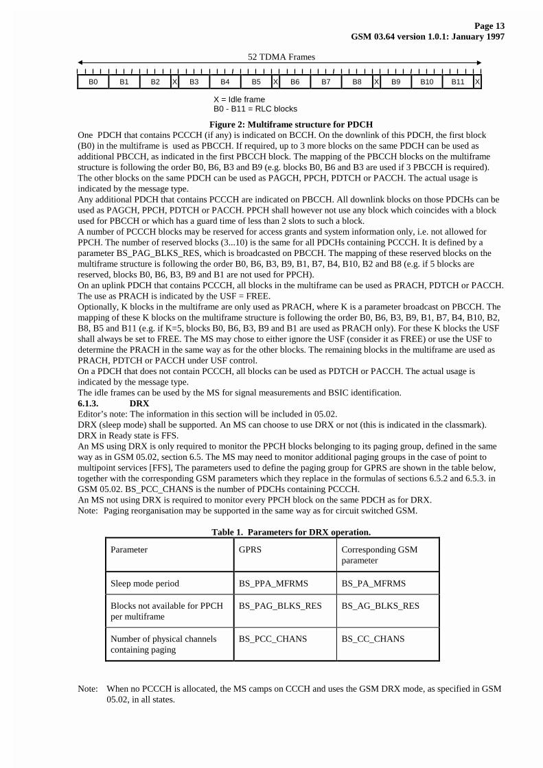
6.1.2. Multiframe Structure for PDCHEditor’s note: The information in this section will be included in GSM 05.01 and 05.02.The mapping in time of the logical channels is defined by a multiframe structure. The multiframe structure for PDCHconsists of 52 TDMA frames, divided into 12 blocks (of 4 frames) and 4 idle frames according to Figure 2Error!Reference source not found..
Page 13GSM 03.64 version 1.0.1: January 1997
52 TDMA Frames
B0 B1 B2 X B3 B4 B5 X B6 B7 B8 X B9 B10 B11 X
X = Idle frameB0 - B11 = RLC blocks
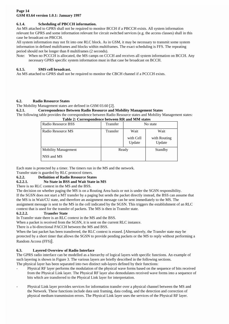
Figure 2: Multiframe structure for PDCHOne PDCH that contains PCCCH (if any) is indicated on BCCH. On the downlink of this PDCH, the first block(B0) in the multiframe is used as PBCCH. If required, up to 3 more blocks on the same PDCH can be used asadditional PBCCH, as indicated in the first PBCCH block. The mapping of the PBCCH blocks on the multiframestructure is following the order B0, B6, B3 and B9 (e.g. blocks B0, B6 and B3 are used if 3 PBCCH is required).The other blocks on the same PDCH can be used as PAGCH, PPCH, PDTCH or PACCH. The actual usage isindicated by the message type.Any additional PDCH that contains PCCCH are indicated on PBCCH. All downlink blocks on those PDCHs can beused as PAGCH, PPCH, PDTCH or PACCH. PPCH shall however not use any block which coincides with a blockused for PBCCH or which has a guard time of less than 2 slots to such a block.A number of PCCCH blocks may be reserved for access grants and system information only, i.e. not allowed forPPCH. The number of reserved blocks (3...10) is the same for all PDCHs containing PCCCH. It is defined by aparameter BS_PAG_BLKS_RES, which is broadcasted on PBCCH. The mapping of these reserved blocks on themultiframe structure is following the order B0, B6, B3, B9, B1, B7, B4, B10, B2 and B8 (e.g. if 5 blocks arereserved, blocks B0, B6, B3, B9 and B1 are not used for PPCH).On an uplink PDCH that contains PCCCH, all blocks in the multiframe can be used as PRACH, PDTCH or PACCH.The use as PRACH is indicated by the USF = FREE.Optionally, K blocks in the multiframe are only used as PRACH, where K is a parameter broadcast on PBCCH. Themapping of these K blocks on the multiframe structure is following the order B0, B6, B3, B9, B1, B7, B4, B10, B2,B8, B5 and B11 (e.g. if K=5, blocks B0, B6, B3, B9 and B1 are used as PRACH only). For these K blocks the USFshall always be set to FREE. The MS may chose to either ignore the USF (consider it as FREE) or use the USF todetermine the PRACH in the same way as for the other blocks. The remaining blocks in the multiframe are used asPRACH, PDTCH or PACCH under USF control.On a PDCH that does not contain PCCCH, all blocks can be used as PDTCH or PACCH. The actual usage isindicated by the message type.The idle frames can be used by the MS for signal measurements and BSIC identification.6.1.3. DRXEditor’s note: The information in this section will be included in 05.02.DRX (sleep mode) shall be supported. An MS can choose to use DRX or not (this is indicated in the classmark).DRX in Ready state is FFS.An MS using DRX is only required to monitor the PPCH blocks belonging to its paging group, defined in the sameway as in GSM 05.02, section 6.5. The MS may need to monitor additional paging groups in the case of point tomultipoint services [FFS], The parameters used to define the paging group for GPRS are shown in the table below,together with the corresponding GSM parameters which they replace in the formulas of sections 6.5.2 and 6.5.3. inGSM 05.02. BS_PCC_CHANS is the number of PDCHs containing PCCCH.An MS not using DRX is required to monitor every PPCH block on the same PDCH as for DRX.Note: Paging reorganisation may be supported in the same way as for circuit switched GSM.
Table 1. Parameters for DRX operation.
Parameter GPRS Corresponding GSMparameter
Sleep mode period BS_PPA_MFRMS BS_PA_MFRMS
Blocks not available for PPCHper multiframe
BS_PAG_BLKS_RES BS_AG_BLKS_RES
Number of physical channelscontaining paging
BS_PCC_CHANS BS_CC_CHANS
Note: When no PCCCH is allocated, the MS camps on CCCH and uses the GSM DRX mode, as specified in GSM05.02, in all states.
Page 14GSM 03.64 version 1.0.1: January 1997
6.1.4. Scheduling of PBCCH information.An MS attached to GPRS shall not be required to monitor BCCH if a PBCCH exists. All system informationrelevant for GPRS and some information relevant for circuit switched services (e.g. the access classes) shall in thiscase be broadcast on PBCCH.All system information may not fit into one RLC block. As in GSM, it may be necessary to transmit some systeminformation in defined multiframes and blocks within multiframes. The exact scheduling is FFS. The repeatingperiod should not be longer than 8 multiframes (2 seconds).Note: When no PCCCH is allocated, the MS camps on CCCH and receives all system information on BCCH. Any
necessary GPRS specific system information must in that case be broadcast on BCCH.
6.1.5. SMS cell broadcast.An MS attached to GPRS shall not be required to monitor the CBCH channel if a PCCCH exists.
6.2. Radio Resource StatesThe Mobility Management states are defined in GSM 03.60 [2].6.2.1. Correspondence Between Radio Resource and Mobility Management StatesThe following table provides the correspondence between Radio Resource states and Mobility Management states:
Table 2: Correspondence between RR and MM statesRadio Resource BSS Transfer No state
Radio Resource MS Transfer Wait
with CellUpdate
Wait
with RoutingUpdate
Mobility Management
NSS and MS
Ready Standby
Each state is protected by a timer. The timers run in the MS and the network.Transfer state is guarded by RLC protocol timers.6.2.2. Definition of Radio Resource States6.2.2.1. No State in BSS and Wait State in MSThere is no RLC context in the MS and the BSS.The decision on whether paging the MS is on a Routing Area basis or not is under the SGSN responsibility.If the SGSN does not start a MT transfer by a paging but sends the packet directly instead, the BSS can assume thatthe MS is in Wait/CU state, and therefore an assignment message can be sent immediately to the MS. Theassignment message is sent to the MS in the cell indicated by the SGSN. This triggers the establishment of an RLCcontext that is used for the transfer of packets. The MS is then in Transfer state.6.2.2.2. Transfer StateIn Transfer state there is an RLC context in the MS and the BSS.When a packet is received from the SGSN, it is sent on the current RLC instance.There is a bi-directional PACCH between the MS and BSS.When the last packet has been transferred, the RLC context is erased. [Alternatively, the Transfer state may beprotected by a short timer that allows the SGSN to provide pending packets or the MS to reply without performing aRandom Access (FFS)] .
6.3. Layered Overview of Radio InterfaceThe GPRS radio interface can be modelled as a hierarchy of logical layers with specific functions. An example ofsuch layering is shown in Figure 3. The various layers are briefly described in the following sections.The physical layer has been separated into two distinct sub-layers defined by their functions:- Physical RF layer performs the modulation of the physical wave forms based on the sequence of bits received
from the Physical Link layer. The Physical RF layer also demodulates received wave forms into a sequence ofbits which are transferred to the Physical Link layer for interpretation.
- Physical Link layer provides services for information transfer over a physical channel between the MS andthe Network. These functions include data unit framing, data coding, and the detection and correction ofphysical medium transmission errors. The Physical Link layer uses the services of the Physical RF layer.

Page 15GSM 03.64 version 1.0.1: January 1997
The lower part of the data link layer is defined by following functions:- The RLC/MAC layer provides services for information transfer over the physical layer of the GPRS radio
interface. These functions include backward error correction procedures enabled by the selectiveretransmission of erroneous blocks. The MAC function arbitrates access to the shared medium between amultitude of MSs and the Network. The RLC/MAC layer uses the services of the Physical Link layer. Thelayer above RLC/MAC (i.e., LLC described in GSM 03.60 [2] [and defined in GSM 04.64 [12]] ) uses theservices of the RLC/MAC layer on the Um interface.
Figure 3: GPRS MS – Network Reference Model
6.4. Physical RF LayerThe GSM Physical RF layer is defined in GSM 05 series recommendations, which specify among other things:- The carrier frequencies characteristics and GSM radio channel structures (GSM 05.02 [4]),- The modulation of the transmitted wave forms and the raw data rates of GSM channels (GSM 05.04 [6]), and- The transmitter and receiver characteristics and performance requirements (GSM 05.05 [7]).
The GSM physical RF layer shall be used as a basis for GPRS with possibility for future modifications.6.5. Physical Link LayerThe Physical Link layer operates above the physical RF layer to provide a physical channel between the MS and theNetwork.6.5.1. Layer ServicesThe purpose of the Physical Link layer is to convey information across the GSM air interface, including RLC/MACinformation. The Physical Link layer supports multiple MSs sharing a single physical channel.The Physical Link layer provides communication between MSs and the Network.The Physical Link layer control functions provide the services necessary to maintain communications capability overthe physical radio channel between the Network and MSs. Radio subsystem link control procedures are currentlyspecified in GSM 05.08 [8]. Network controlled handovers are not used in the GPRS service. Instead, routingupdates and cell updates are used.6.5.2. Layer FunctionsThe Physical Link layer is responsible for:- Forward Error Correction (FEC) coding, allowing the detection and correction of transmitted code words and
the indication of uncorrectable code words. The coding schemes are described in section 6.5.4.
- Rectangular interleaving of one RLC/MAC block over four bursts in consecutive TDMA frames, as specifiedin GSM 05.03 [5].
- Procedures for detecting physical link congestion.
The Physical Link layer control functions include:- Synchronisation procedures, including means for determining and adjusting the MS Timing Advance to
correct for variances in propagation delay (radio subsystem synchronisation is currently specified in GSM05.10 [9]),
- Monitoring and evaluation procedures for radio link signal quality,
- Cell (re-)selection procedures,
- Transmitter power control procedures, and
- Battery power conservation procedures, e.g. Discontinuous Reception (DRX) procedures.
Um Network
SNDCPLLC
(Note)RLC
MACPhys. LinkPhys. RF
SNDCPLLC
RLC
MACPhys. LinkPhys. RF
MS
Scope of GSM 03.60
Scope of GSM 04.60Note: In the network the LLC issplit between BSS and SGSN. TheBSS functionality is called LLCrelay.
Page 16GSM 03.64 version 1.0.1: January 1997
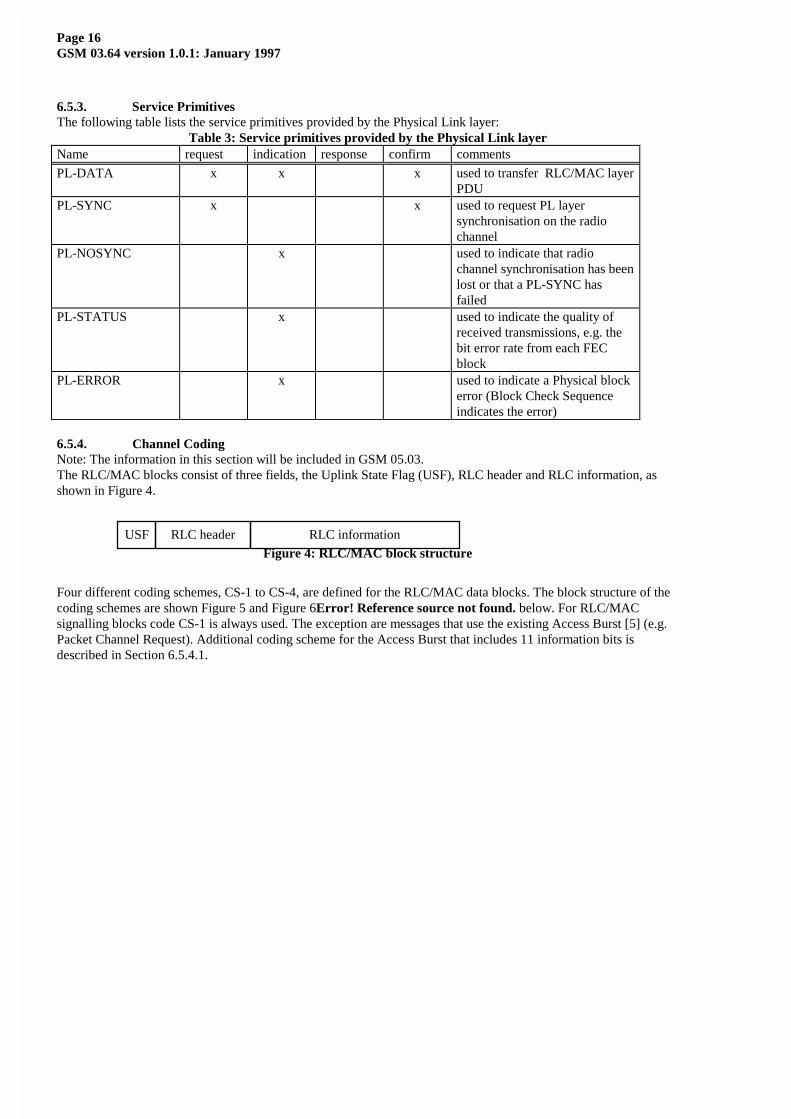
6.5.3. Service PrimitivesThe following table lists the service primitives provided by the Physical Link layer:
Table 3: Service primitives provided by the Physical Link layerName request indication response confirm comments
PL-DATA x x x used to transfer RLC/MAC layerPDU
PL-SYNC x x used to request PL layersynchronisation on the radiochannel
PL-NOSYNC x used to indicate that radiochannel synchronisation has beenlost or that a PL-SYNC hasfailed
PL-STATUS x used to indicate the quality ofreceived transmissions, e.g. thebit error rate from each FECblock
PL-ERROR x used to indicate a Physical blockerror (Block Check Sequenceindicates the error)
6.5.4. Channel CodingNote: The information in this section will be included in GSM 05.03.The RLC/MAC blocks consist of three fields, the Uplink State Flag (USF), RLC header and RLC information, asshown in Figure 4.
Figure 4: RLC/MAC block structure
Four different coding schemes, CS-1 to CS-4, are defined for the RLC/MAC data blocks. The block structure of thecoding schemes are shown Figure 5 and Figure 6Error! Reference source not found. below. For RLC/MACsignalling blocks code CS-1 is always used. The exception are messages that use the existing Access Burst [5] (e.g.Packet Channel Request). Additional coding scheme for the Access Burst that includes 11 information bits isdescribed in Section 6.5.4.1.
RLC headerUSF RLC information

Page 17GSM 03.64 version 1.0.1: January 1997
Figure 5: Block structure for CS-1 to CS-3
Figure 6: Block structure for CS-4
The first step of the coding procedure is to add a Block Check Sequence (BCS) for error detection.Note: Of implementation reasons it is convenient to regard the error detection as part of the Physical Link Layer,even though the Backward Error Correction procedures belong to the RLC.For CS-1 - CS-3, the second step consists of pre-coding USF (except for CS-1), adding four tail bits and aconvolutional coding for error correction that is punctured to give the desired coding rate. For CS-4 there is no coding for error correction.The details of the codes are shown in a table below, including:
• the length of each field
• the number of coded bits (after adding tail bits and convolutional coding)
• the number of punctured bits
• the data rate, including the RLC header and RLC information
rate 1/2 convolutional coding
puncturing
456 bits
RLC headerUSF RLC information BCS
blockcode
no coding
456 bits
RLC headerUSF RLC information BCS

Page 18GSM 03.64 version 1.0.1: January 1997
Table 4: Coding parameters for the coding schemes.
Scheme Code rate USF Pre-codedUSF
RLC blockexcl. USF
BCS Tail Codedbits
Puncturedbits
Data ratekb/s
CS-1 1/2 3 3 181 40 4 456 0 9.05
CS-2 ≈2/3 3 6 268 16 4 588 132 13.4
CS-3 ≈3/4 3 6 312 16 4 676 220 15.6
CS-4 1 3 12 428 16 - 456 - 21.4
CS-1 is the same coding scheme as specified for SDCCH in GSM 05.03 [5]. It consists of a half rate convolutionalcode for FEC and a 40 bit FIRE code for BCS (and optionally FEC).CS-2 and CS-3 are punctured versions of the same half rate convolutional code as CS-1 for FEC. The coded bits arenumbered starting from zero.
For CS-2 the punctured bits are number 4*i+3, i = 3,..., 146 except for i = 9, 21, 33, 45, 57, 69, 81, 93, 105,117, 129 and 141. Hence none of the first 12 bits is punctured.
Note: For CS-2 the puncturing pattern has to be adjusted to the format of the future new TRAU frame format tobe used on the Abis interface (e.g. more bits have to be punctured in order to give place for the RLCsignalling).
For CS-3 the punctured bits are number 6*i+3 and 6*i+5, i = 2,..., 111.CS-4 has no FEC.CS-2 to CS-4 use the same 16 bit CRC for BCS. The CRC is calculated over the whole uncoded RLC blockincluding USF. The generator polynomial is:
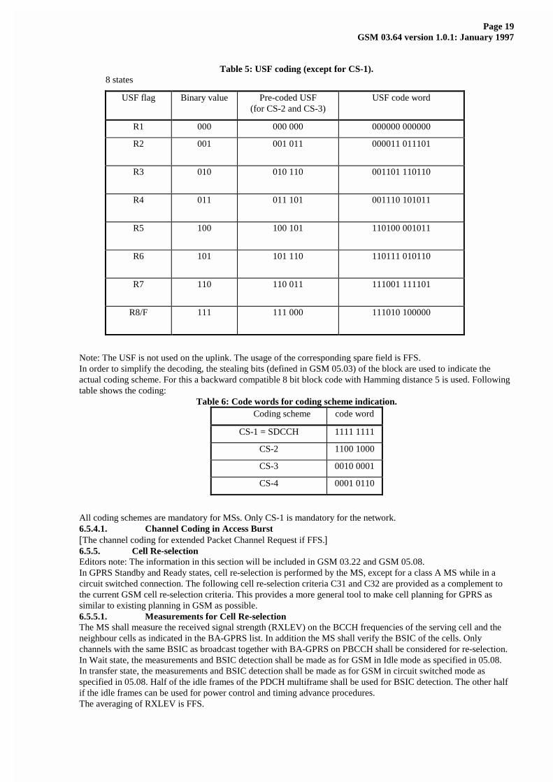
G = 1+X5 + X12 + X16.The USF has 8 states, which are represented by a binary 3 bit field in the RLC block.For CS-1, the whole RLC block is convolutionally coded and USF must be decoded as part of the data.All other coding schemes generate the same 12 bit code for USF, which is shaded in the figures. For these cases theUSF can be decoded either as a block code, with a minimum Hamming distance of 5, or as part of the data.For CS-2 and CS-3, this is achieved by first mapping it into a 6 bit pre-coded value and then applying theconvolutional code to the whole block without puncturing the first 12 coded bits, which only depends on USF.For CS-4 the USF bits are directly mapped into the 12 bit block code.Following table shows the USF coding:
Page 19GSM 03.64 version 1.0.1: January 1997
Table 5: USF coding (except for CS-1).8 states
USF flag Binary value Pre-coded USF(for CS-2 and CS-3)
USF code word
R1 000 000 000 000000 000000
R2 001 001 011 000011 011101
R3 010 010 110 001101 110110
R4 011 011 101 001110 101011
R5 100 100 101 110100 001011
R6 101 101 110 110111 010110
R7 110 110 011 111001 111101
R8/F 111 111 000 111010 100000
Note: The USF is not used on the uplink. The usage of the corresponding spare field is FFS.In order to simplify the decoding, the stealing bits (defined in GSM 05.03) of the block are used to indicate theactual coding scheme. For this a backward compatible 8 bit block code with Hamming distance 5 is used. Followingtable shows the coding:
Table 6: Code words for coding scheme indication.Coding scheme code word
CS-1 = SDCCH 1111 1111
CS-2 1100 1000
CS-3 0010 0001
CS-4 0001 0110
All coding schemes are mandatory for MSs. Only CS-1 is mandatory for the network.6.5.4.1. Channel Coding in Access Burst[The channel coding for extended Packet Channel Request if FFS.]6.5.5. Cell Re-selectionEditors note: The information in this section will be included in GSM 03.22 and GSM 05.08.In GPRS Standby and Ready states, cell re-selection is performed by the MS, except for a class A MS while in acircuit switched connection. The following cell re-selection criteria C31 and C32 are provided as a complement tothe current GSM cell re-selection criteria. This provides a more general tool to make cell planning for GPRS assimilar to existing planning in GSM as possible.6.5.5.1. Measurements for Cell Re-selectionThe MS shall measure the received signal strength (RXLEV) on the BCCH frequencies of the serving cell and theneighbour cells as indicated in the BA-GPRS list. In addition the MS shall verify the BSIC of the cells. Onlychannels with the same BSIC as broadcast together with BA-GPRS on PBCCH shall be considered for re-selection.In Wait state, the measurements and BSIC detection shall be made as for GSM in Idle mode as specified in 05.08.In transfer state, the measurements and BSIC detection shall be made as for GSM in circuit switched mode asspecified in 05.08. Half of the idle frames of the PDCH multiframe shall be used for BSIC detection. The other halfif the idle frames can be used for power control and timing advance procedures.The averaging of RXLEV is FFS.

Page 20GSM 03.64 version 1.0.1: January 1997
6.5.5.2. Cell Re-selection AlgorithmThe following cell (re-)selection steps shall be followed ((s) and (n) denote serving cell and neighbour cellrespectively).1 Path loss criterion (C1)
The path loss criterion C1 ≥ 0, as defined in GSM 05.08, shall be used as a minimum signal strength criterion forcell selection for GPRS in the same way as for GSM in Idle mode.
2. Signal strength threshold criterion (C31) for hierarchical cell structures (HCS)The HCS signal strength threshold criterion (C31) shall be used to decide whether the cell is qualified forprioritised hierarchical cell re-selection.
C31(s) = RXLEV(s) - HCS_THR(s) ≥ 0 (serving cell)C31(n) = RXLEV(n) - HCS_THR(n) ≥ 0 (neighbour cell)where HCS_THR is the signal threshold for applying HCS re-selection.
3. Cell ranking (C32)The cell ranking criterion (C32) shall be used to select cells among those with the same priority.
C32(s) = RXLEV(s) - GPRS_RESELECTION_PARAMETER_1(s) (serving cell)C32(n) = RXLEV(n) - GPRS_RESELECTION_PARAMETER_1(n) -
GPRS_RESELECTION_PARAMETER_2(n) * H(RXLEV(s) - RXLEV_TRH(s)) -TEMPORARY_OFFSET(n) * H(PENALTY_TIME(n) - T(n)) (neighbour cell)
whereGPRS_RESELECTION_PARAMETER_1 applies an offset and hysteresis value to each cellGPRS_RESELECTION_PARAMETER_2 applies an additional hysteresis offset if serving cell has highsignal strengthH(x) = 0 for x < 0
1 for x ≥ 0RXLEV_TRH(s) is the signal threshold for applying additional hysteresisTEMPORARY_OFFSET, PENALTY_TIME and T are defined in GSM 05.08.
4. Cell re-selection rulesThe MS shall select the cell having the highest C32 value among those that have the highest priority class amongthose that fulfil the criterion C31 ≥ 0.Note: The priority classes may correspond to different HCS layers. They may also be used for other purposes.
[FFS]If no cells fulfil the criterion C31 ≥ 0, the MS shall select the cell having the highest C32 value among all cells.
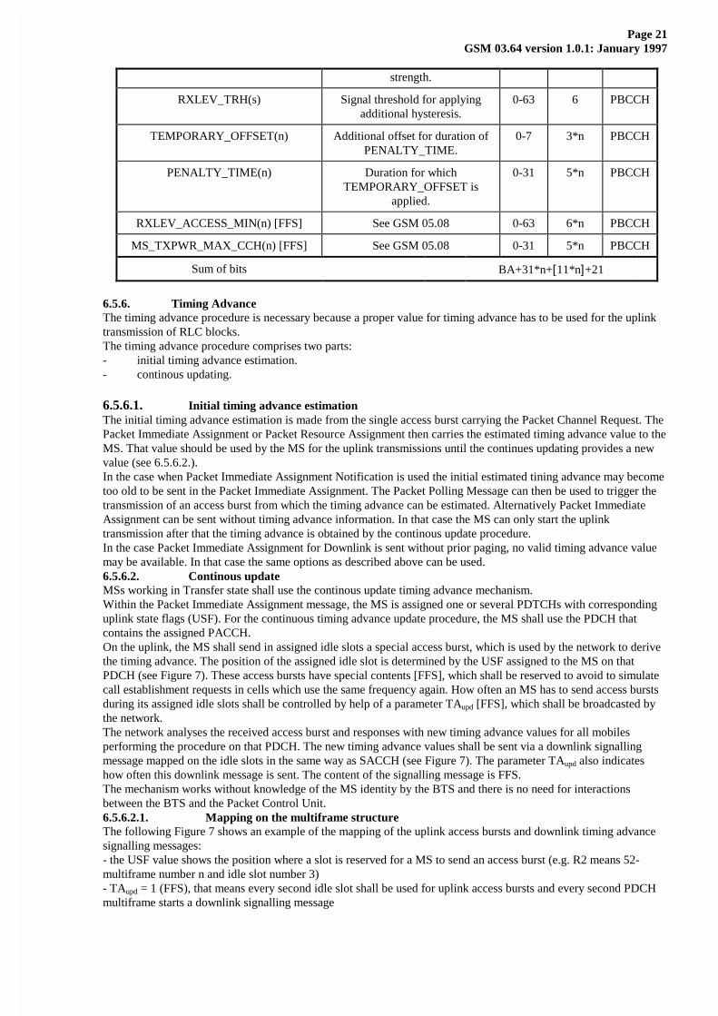
It shall be possible to order an MS in Ready state to send a measurement report to the network. The measurementreport shall be regular packet transmission, addressed to the proper network entity. The information contents of themeasurement report if FFS.It shall be possible for the network to order an individual MS in Ready state to perform cell re-selection to a cellappointed by the network, possibly in combination with a punishment parameter to prevent the MS immediatereturning to the original cell. A network induces cell re-selection shall temporarily override the MS originated cell-selection.6.5.5.3. Broadcast InformationA GPRS BA list shall be broadcast on PBCCH. It identifies the neighbour cells, including BSIC, that shall beconsidered for GPRS cell (re-)selection (not necessary the same as for GSM in Idle or circuit switched mode).For each neighbour cell in this BA list, the parameters described below shall also be broadcast. In order to simplifythe cell re-selection task for the MS, the C1 parameters, as defined in GSM 05.08, for all neighbour cells could alsobe broadcast on PBCCH (FFS).The required parameters are shown in the following table.
Table 7: Broadcast parameters.
Parameter name Description Range Bits Channel
BA-GPRS BCCH Allocation for GPRS cellre-selection.
SeeBCCH
PBCCH
BSIC(n) Base Station Identity Code 0-63 6*n PBCCH
Priority class (s+n) [FFS] The HCS priority for the cells 0-7 3*(n+1) PBCCH
HCS_THR(s+n) HCS signal strength threshold 0-63 6*(n+1) PBCCH
GPRS_RESELECT_OFFSET(s+n) GPRS cell re-selection offset andhysteresis.
0-63 6(n+1) PBCCH
GPRS_RESELECT_HYST(n) Additional hysteresis applied ifserving cell has high signal
0-3 2(n) PBCCH
Page 21GSM 03.64 version 1.0.1: January 1997
strength.
RXLEV_TRH(s) Signal threshold for applyingadditional hysteresis.
0-63 6 PBCCH
TEMPORARY_OFFSET(n) Additional offset for duration ofPENALTY_TIME.
0-7 3*n PBCCH
PENALTY_TIME(n) Duration for whichTEMPORARY_OFFSET is
applied.
0-31 5*n PBCCH
RXLEV_ACCESS_MIN(n) [FFS] See GSM 05.08 0-63 6*n PBCCH
MS_TXPWR_MAX_CCH(n) [FFS] See GSM 05.08 0-31 5*n PBCCH
Sum of bits BA+31*n+[11*n]+21
6.5.6. Timing AdvanceThe timing advance procedure is necessary because a proper value for timing advance has to be used for the uplinktransmission of RLC blocks.The timing advance procedure comprises two parts:- initial timing advance estimation.- continous updating.
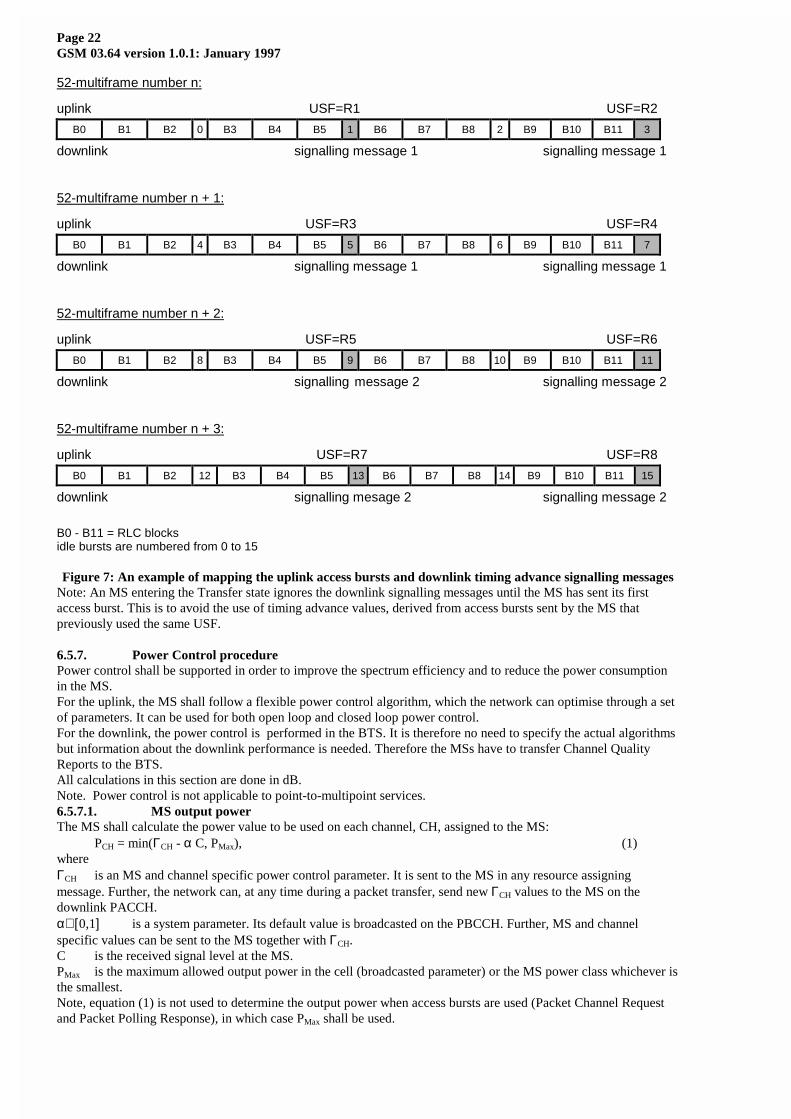
6.5.6.1. Initial timing advance estimationThe initial timing advance estimation is made from the single access burst carrying the Packet Channel Request. ThePacket Immediate Assignment or Packet Resource Assignment then carries the estimated timing advance value to theMS. That value should be used by the MS for the uplink transmissions until the continues updating provides a newvalue (see 6.5.6.2.).In the case when Packet Immediate Assignment Notification is used the initial estimated tining advance may becometoo old to be sent in the Packet Immediate Assignment. The Packet Polling Message can then be used to trigger thetransmission of an access burst from which the timing advance can be estimated. Alternatively Packet ImmediateAssignment can be sent without timing advance information. In that case the MS can only start the uplinktransmission after that the timing advance is obtained by the continous update procedure.In the case Packet Immediate Assignment for Downlink is sent without prior paging, no valid timing advance valuemay be available. In that case the same options as described above can be used.6.5.6.2. Continous updateMSs working in Transfer state shall use the continous update timing advance mechanism.Within the Packet Immediate Assignment message, the MS is assigned one or several PDTCHs with correspondinguplink state flags (USF). For the continuous timing advance update procedure, the MS shall use the PDCH thatcontains the assigned PACCH.On the uplink, the MS shall send in assigned idle slots a special access burst, which is used by the network to derivethe timing advance. The position of the assigned idle slot is determined by the USF assigned to the MS on thatPDCH (see Figure 7). These access bursts have special contents [FFS], which shall be reserved to avoid to simulatecall establishment requests in cells which use the same frequency again. How often an MS has to send access burstsduring its assigned idle slots shall be controlled by help of a parameter TAupd [FFS], which shall be broadcasted bythe network.The network analyses the received access burst and responses with new timing advance values for all mobilesperforming the procedure on that PDCH. The new timing advance values shall be sent via a downlink signallingmessage mapped on the idle slots in the same way as SACCH (see Figure 7). The parameter TAupd also indicateshow often this downlink message is sent. The content of the signalling message is FFS.The mechanism works without knowledge of the MS identity by the BTS and there is no need for interactionsbetween the BTS and the Packet Control Unit.6.5.6.2.1. Mapping on the multiframe structureThe following Figure 7 shows an example of the mapping of the uplink access bursts and downlink timing advancesignalling messages:- the USF value shows the position where a slot is reserved for a MS to send an access burst (e.g. R2 means 52-multiframe number n and idle slot number 3)- TAupd = 1 (FFS), that means every second idle slot shall be used for uplink access bursts and every second PDCHmultiframe starts a downlink signalling message
Page 22GSM 03.64 version 1.0.1: January 1997
52-multiframe number n:
uplink USF=R1 USF=R2
B0 B1 B2 0 B3 B4 B5 1 B6 B7 B8 2 B9 B10 B11 3
downlink signalling message 1 signalling message 1
52-multiframe number n + 1:
uplink USF=R3 USF=R4
B0 B1 B2 4 B3 B4 B5 5 B6 B7 B8 6 B9 B10 B11 7
downlink signalling message 1 signalling message 1
52-multiframe number n + 2:
uplink USF=R5 USF=R6
B0 B1 B2 8 B3 B4 B5 9 B6 B7 B8 10 B9 B10 B11 11
downlink signalling message 2 signalling message 2
52-multiframe number n + 3:
uplink USF=R7 USF=R8
B0 B1 B2 12 B3 B4 B5 13 B6 B7 B8 14 B9 B10 B11 15
downlink signalling mesage 2 signalling message 2
B0 - B11 = RLC blocksidle bursts are numbered from 0 to 15
Figure 7: An example of mapping the uplink access bursts and downlink timing advance signalling messagesNote: An MS entering the Transfer state ignores the downlink signalling messages until the MS has sent its firstaccess burst. This is to avoid the use of timing advance values, derived from access bursts sent by the MS thatpreviously used the same USF.
6.5.7. Power Control procedurePower control shall be supported in order to improve the spectrum efficiency and to reduce the power consumptionin the MS.For the uplink, the MS shall follow a flexible power control algorithm, which the network can optimise through a setof parameters. It can be used for both open loop and closed loop power control.For the downlink, the power control is performed in the BTS. It is therefore no need to specify the actual algorithmsbut information about the downlink performance is needed. Therefore the MSs have to transfer Channel QualityReports to the BTS.All calculations in this section are done in dB.Note. Power control is not applicable to point-to-multipoint services.6.5.7.1. MS output powerThe MS shall calculate the power value to be used on each channel, CH, assigned to the MS:
PCH = min(ΓCH - α C, PMax), (1)whereΓCH is an MS and channel specific power control parameter. It is sent to the MS in any resource assigningmessage. Further, the network can, at any time during a packet transfer, send new ΓCH values to the MS on thedownlink PACCH.α∈[ 0,1] is a system parameter. Its default value is broadcasted on the PBCCH. Further, MS and channelspecific values can be sent to the MS together with ΓCH.C is the received signal level at the MS.PMax is the maximum allowed output power in the cell (broadcasted parameter) or the MS power class whichever isthe smallest.Note, equation (1) is not used to determine the output power when access bursts are used (Packet Channel Requestand Packet Polling Response), in which case PMax shall be used.
Page 23GSM 03.64 version 1.0.1: January 1997
6.5.7.2. BTS output powerThe BTS shall use constant power on those PDCHs which have PCCCH functionality. On the other PDCHs,downlink power control may be used. Thus, a procedure may be implemented in the network to control the power ofthe downlink transmission based on the Channel Quality Reports. The algorithm needs not to be specified here andcan be optimised by the network operator.6.5.7.3. Measurements at MS sideA procedure shall be implemented in the MS to monitor periodically the downlink Rx signal level and quality fromits serving cell. The measurements are done on the assigned PDCH(s) if the MS is transferring data, otherwise themeasurements are done on PCCCH or BCCH.6.5.7.3.1. Deriving the C valueThis section comprises information about how the MS shall derive the C value in (1).Wait stateIn Wait state, the MS shall periodically measure the signal strength of the PCCCH or, if PCCCH is not existing, theBCCH.When PCCCH exists, the MS shall measure the signal strength of NAVG RLC blocks during a measurement period ofTAVG multiframes (multiframe of PDCH).When PCCCH does not exist, the MS shall measure the signal strength of NAVG blocks (of CCCH or BCCH) duringa measurement period of TAVG multiframes (multiframe of CCCH).The signal strength of each block, SSblock n, is the mean of the signal strength of the four normal bursts that constitutethe block. Further, the number of bit errors shall be derived for each RLC block. Then the C value for the block iscalculated:
Cblock n = f3 (SSblock n, #bit errorsblock n) - Pbblock n . (2)Here, the function f3 is FFS.Pbblock n is the BFS output power (relative to a BTS specific reference level), which is transferred in the RLC blockheader. If the block is not received correctly, the corresponding measurement is discarded. The corrected C valueprovides a measure of the path loss (Path loss = BTS reference level - corrected C).Finally, the Cblock n valuesparameters are filtered with a running average filter:
Cn = (1-a) ∗ Cn-1 + a ∗ Cblock n, C0=0, (3)where a is the forgetting factor. The value of a is FFS.An RMS value of the corrected signal levels may also be derived and included in the channel quality report (see6.5.7.3.2) [FFS].The current Cn value shall be used in (1) when the MS transfers its first RLC block.NAVG and TAVG are broadcasted on PBCCH or, if PBCCH does not exist, on BCCH.Transfer stateIn Transfer state, the MS measures the signal strength of the PDCH where the MS receives/transmits PACCH. Foreach downlink RLC block Cblock n shall be derived according to (2). Finally, the Cblock n valueparameters are filteredwith a running average filter:
Cn = (1-b) ∗ Cn-1 + b ∗ Cblock n, (4)where b is the forgetting factor. The value of b is FFS. C0 is obtained from the measurements done when nottransferring data.The C valueparameter in (1) (and thus PCH) shall be updated to the current Cn value every TAVG_T multiframes orwhenever the MS receives new ΓCH values (and perhaps also a new α value). Further, if the broadcasted parameterUPDATE_C is set, then the MS shall update the C value each time a new Cn value is obtained.UPDATE_C and TAVG_T are broadcasted on PBCCH or, if PBCCH does not exist, on BCCH.6.5.7.3.2. Derivation of Channel Quality ReportThe channel quality is measured as the interference signal level during the idle frames of the multiframe, when theown cell is not transmitting.Transfer stateIn Transfer state, the MS shall measure the interference signal strength of all eight channels (slots) on the samecarrier as the assigned PDCHs. Some of the idle frames shall be used for this, while the others are used for BSICidentification and timing advance signalling [FFS].The slots that the MS measures on can be either idle or used by SACCH. The MS shall therefore, for each slot, takethe minimum signal strength SSCH,n of two consecutive idle frames. Thus the SACCH frames are avoided (except fora TCH/H with two MSs) and only the interference is measured. The measured interference shall be average in arunning average filter:
γCH,n = (1-d) ∗ γCH,n-1 + d ∗ SSCH,n, (5)where d is the forgetting factor. The value of d is FFS.For each slot, the MS shall perform at least NAVG_I measurements of SSCH,n before valid γCH values can bedetermined.The MS shall transfer the 8 γCH values and the C value (see 6.5.7.3.1) to the network in the Channel Quality Reportincluded in the ACK/NACK message.

Page 24GSM 03.64 version 1.0.1: January 1997
NAVG_I is broadcasted on PBCCH or, if PBCCH does not exist, on BCCH.Wait stateIn wait state, the MS shall measure the interference signal strength on certian channels which are indicated on thePBCCH. If no channels are indicated or if PCCCH does not exist, the MS shall not performe these measurements.These measurements shall be made in the idle frames in the same way as described above and averaged with arunning average filter:
γCH,n = (1-e) ∗ γCH,n-1 + e ∗ SSCH,n. (6)For each channel, the MS shall perform at least NAVG_I interference measurements during a period of TAVG_I
multiframes (multiframe of PDCH) before valid γCH values can be determined. Upon entering Transfer state, the 8lowest γCH,n values and the C value (see 6.5.7.3.1) shall be transferred to the network in the Channel Quality Reportincluded in the Packet Resource Request or Packet Paging Response. If none of these messages are used, no ChannelQuality Report is sent.TAVG_I and NAVG_I are broadcasted on PBCCH.On network commandWhen the MS is in Wait state, Tthe network can order an MS to do interference measurements of certain channels,TCHs or PDCHs, when the MS is in Wait state. The MS shall in such case do the measurements and filtering in thesame way as described above, except that . Tthe channels to be measured and the filtering parameters are, thenumber of samples the MS shall make and the minimum time that the measurement should be done over (measuredin multiframes of PDCH) is given in the Measurement Order. The averaged measurementsof these samples shall thenbe transferred to the network as a Measurement Performed message.6.5.7.4. Measurements at BSS sideA procedure shall be implemented in the BSS to monitor the uplink Rx signal level and quality on each uplinkPDCH, active as well as inactive.The BSS shall also measure the Rx signal level and the quality of a specific MS packet transfer.
Page 25GSM 03.64 version 1.0.1: January 1997
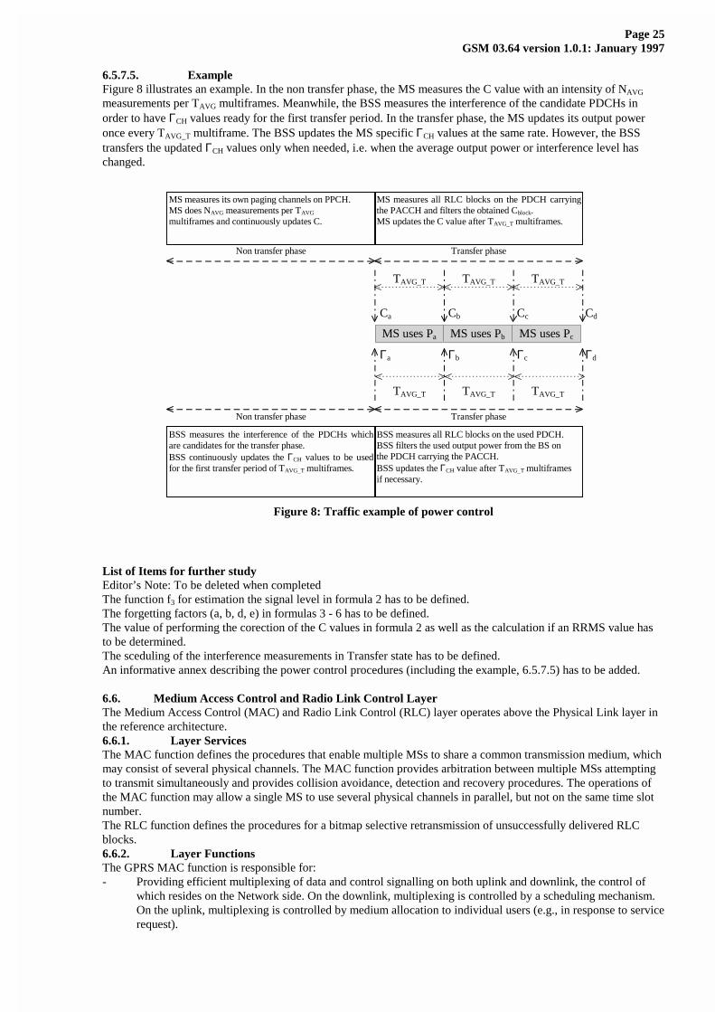
6.5.7.5. ExampleFigure 8 illustrates an example. In the non transfer phase, the MS measures the C value with an intensity of NAVG
measurements per TAVG multiframes. Meanwhile, the BSS measures the interference of the candidate PDCHs inorder to have ΓCH values ready for the first transfer period. In the transfer phase, the MS updates its output poweronce every TAVG_T multiframe. The BSS updates the MS specific ΓCH values at the same rate. However, the BSStransfers the updated ΓCH values only when needed, i.e. when the average output power or interference level haschanged.
Non transfer phase Transfer phase
TAVG_T TAVG_T TAVG_T
MS measures all RLC blocks on the PDCH carryingthe PACCH and filters the obtained Cblock.MS updates the C value after TAVG_T multiframes.
MS measures its own paging channels on PPCH.MS does NAVG measurements per TAVG
multiframes and continuously updates C.
Cc CdCbCa
TAVG_T TAVG_T TAVG_T
Non transfer phase Transfer phase
BSS measures all RLC blocks on the used PDCH.BSS filters the used output power from the BS onthe PDCH carrying the PACCH.BSS updates the ΓCH value after TAVG_T multiframesif necessary.
BSS measures the interference of the PDCHs whichare candidates for the transfer phase.BSS continuously updates the ΓCH values to be usedfor the first transfer period of TAVG_T multiframes.
Γc ΓdΓbΓa
MS uses Pa MS uses Pb MS uses Pc
Figure 8: Traffic example of power control
List of Items for further studyEditor’s Note: To be deleted when completedThe function f3 for estimation the signal level in formula 2 has to be defined.The forgetting factors (a, b, d, e) in formulas 3 - 6 has to be defined.The value of performing the corection of the C values in formula 2 as well as the calculation if an RRMS value hasto be determined.The sceduling of the interference measurements in Transfer state has to be defined.An informative annex describing the power control procedures (including the example, 6.5.7.5) has to be added.
6.6. Medium Access Control and Radio Link Control LayerThe Medium Access Control (MAC) and Radio Link Control (RLC) layer operates above the Physical Link layer inthe reference architecture.6.6.1. Layer ServicesThe MAC function defines the procedures that enable multiple MSs to share a common transmission medium, whichmay consist of several physical channels. The MAC function provides arbitration between multiple MSs attemptingto transmit simultaneously and provides collision avoidance, detection and recovery procedures. The operations ofthe MAC function may allow a single MS to use several physical channels in parallel, but not on the same time slotnumber.The RLC function defines the procedures for a bitmap selective retransmission of unsuccessfully delivered RLCblocks.6.6.2. Layer FunctionsThe GPRS MAC function is responsible for:- Providing efficient multiplexing of data and control signalling on both uplink and downlink, the control of
which resides on the Network side. On the downlink, multiplexing is controlled by a scheduling mechanism.On the uplink, multiplexing is controlled by medium allocation to individual users (e.g., in response to servicerequest).
Page 26GSM 03.64 version 1.0.1: January 1997
- For mobile originated channel access, contention resolution between channel access attempts, includingcollision detection and recovery.
- For mobile terminated channel access, scheduling of access attempts, including queuing of packet accesses.
- Priority handling.
The GPRS RLC function is responsible for:- Interface primitives allowing the transfer of Logical Link Control layer PDUs (LLC-PDU) between the LLC
layer and the MAC function.
- Segmentation and re-assembly of LLC-PDUs into RLC blocks.
- Backward Error Correction (BEC) procedures enabling the selective retransmission of uncorrectable codewords. Note: The Block Check Sequence for error detection is provided by the Physical Link Layer.
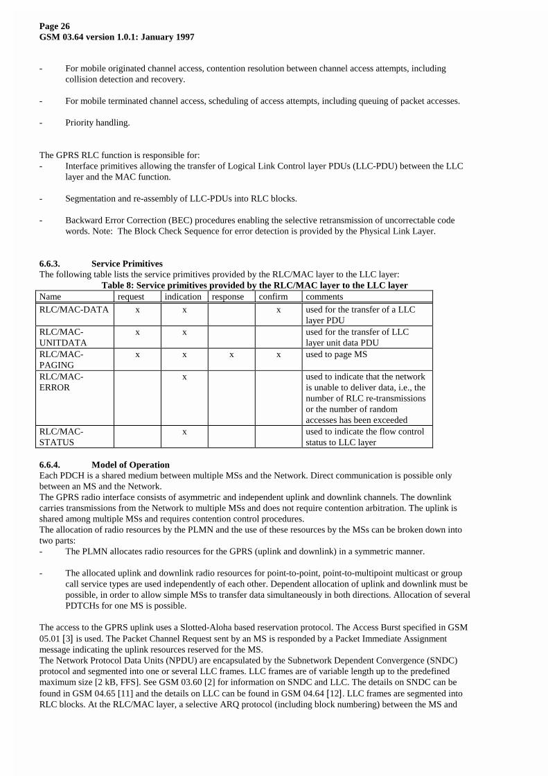
6.6.3. Service PrimitivesThe following table lists the service primitives provided by the RLC/MAC layer to the LLC layer:
Table 8: Service primitives provided by the RLC/MAC layer to the LLC layerName request indication response confirm comments
RLC/MAC-DATA x x x used for the transfer of a LLClayer PDU
RLC/MAC-UNITDATA
x x used for the transfer of LLClayer unit data PDU
RLC/MAC-PAGING
x x x x used to page MS
RLC/MAC-ERROR
x used to indicate that the networkis unable to deliver data, i.e., thenumber of RLC re-transmissionsor the number of randomaccesses has been exceeded
RLC/MAC-STATUS
x used to indicate the flow controlstatus to LLC layer
6.6.4. Model of OperationEach PDCH is a shared medium between multiple MSs and the Network. Direct communication is possible onlybetween an MS and the Network.The GPRS radio interface consists of asymmetric and independent uplink and downlink channels. The downlinkcarries transmissions from the Network to multiple MSs and does not require contention arbitration. The uplink isshared among multiple MSs and requires contention control procedures.The allocation of radio resources by the PLMN and the use of these resources by the MSs can be broken down intotwo parts:- The PLMN allocates radio resources for the GPRS (uplink and downlink) in a symmetric manner.
- The allocated uplink and downlink radio resources for point-to-point, point-to-multipoint multicast or groupcall service types are used independently of each other. Dependent allocation of uplink and downlink must bepossible, in order to allow simple MSs to transfer data simultaneously in both directions. Allocation of severalPDTCHs for one MS is possible.
The access to the GPRS uplink uses a Slotted-Aloha based reservation protocol. The Access Burst specified in GSM05.01 [3] is used. The Packet Channel Request sent by an MS is responded by a Packet Immediate Assignmentmessage indicating the uplink resources reserved for the MS.The Network Protocol Data Units (NPDU) are encapsulated by the Subnetwork Dependent Convergence (SNDC)protocol and segmented into one or several LLC frames. LLC frames are of variable length up to the predefinedmaximum size [2 kB, FFS]. See GSM 03.60 [2] for information on SNDC and LLC. The details on SNDC can befound in GSM 04.65 [11] and the details on LLC can be found in GSM 04.64 [12]. LLC frames are segmented intoRLC blocks. At the RLC/MAC layer, a selective ARQ protocol (including block numbering) between the MS and
Page 27GSM 03.64 version 1.0.1: January 1997
the Network provides retransmission of RLC blocks in error. When a complete LLC frame is successfully transferredacross the RLC layer, it is forwarded to the LLC layer.

Page 28GSM 03.64 version 1.0.1: January 1997
BH
Figure 9: Transmission and reception data flow
6.6.4.1. Uplink State FlagThe uplink state flag (USF) is used on PDCH to allow multiplexing of RLC blocks from a number of MSs.When the SDCCH coding scheme is used, the USF comprises 3 bits at the beginning of each RLC block that is senton the downlink. It enables the coding of 8 different USF states which are used to multiplex the uplink traffic.On PCCCH, one USF value is used to denote PRACH (USF=FREE). The other USF values USF=R1/R2/...R7 areused to reserve the uplink for 7 different MSs. On PDCHs not carrying PCCCH, the eight USF valuesUSF=R1/R2/.../R8 are used to reserve the uplink for 8 different MSs.6.6.4.2. Temporary Flow IdentityThe method of implementing the selective ARQ protocol on the RLC block level includes the assignment of aTemporary Flow Identity (TFI) to each Temporary Block Flow (TBF) transmitted to/from an MS. One TBF maycomprise a number of LLC frames. The assigned TFI is unique among concurrent LLC frame transfer sequences in acell and is used instead of the MS identity in the RLC/MAC layer. The TFI is assigned in a resource assignmentmessage that precedes the transfer of LLC frames belonging to one TBF to/from the MS. The same TFI is includedin every RLC block header belonging to a particular TBF as well as in the control messages associated to the LLCframe transfer (e.g. acknowledgements) in order to address the peer RLC entities. The length of TFI is 7 bits.
6.6.4.3. Selective ARQ OperationThe transfer of RLC blocks is controlled by a selective ARQ mechanism coupled with the modulo-[128] numberingof the RLC blocks within one Temporary Block Flow. The sending side (the MS or the network) transmits blockswithin a window of [64] blocks and the receiving side periodically sends Packet Temporary Ack/Nack message.Every such message acknowledges all correctly received RLC blocks up to an indicated block number, thus“moving” the beginning of the sending window on the sending side. Additionally, the bitmap that starts at the sameRLC block is used to selectively request erroneously received RLC blocks for retransmission. The sending side thenretransmits the erroneous RLC blocks, eventually resulting in further sliding the sending window. The PacketTemporary Ack/Nack message does not include any change in the current assignment (and thus does not have to beacknowledged when sent on downlink). A missing Packet Temporary Ack/Nack is not critical and a new one can beissued whenever.6.6.4.4. Mobile Originated Packet Transfer6.6.4.4.1. Uplink Access
Figure 10: Access and allocation for the 1 or 2 phase packet access, uplink packet transferAn MS initiates a packet transfer by making a Packet Channel Request on PRACH or RACH. The network respondson PAGCH or AGCH respectively. It is possible to use one or two phase packet access method (see Figure 10).In the one phase access, the Packet Channel Request is responded by the network with the Packet ImmediateAssignment reserving the resources on PDCH(s) for uplink transfer of a number of RLC blocks. The reservation isdone accordingly to the information about the requested resources that is comprised in the Packet Channel Request.On RACH, there is only one cause value available for denoting GPRS and the network can assign uplink resources
FH
Upper layers(SNDCP layer)
MS Network
LLC layer
RLC/MAC layer
Physical layer
Packet Channel RequestPacket Immediate Assignment
Packet Resource Request
Packet Resource Assignment
Information field (SNDC PDU) FCS
Normal burst Normal burst
PRACH or RACH
Normal burst
PAGCH or AGCH
Normal burst
PACCH
PACCH
(Optional)
Info field
(Optional)
BH BCSRLCblocks
LLC frame
Primaryblock
Followingblock
Info field BCS Info field BH BCS
FH = Frame HeaderFCS = Frame Check SequenceBH = Block HeaderBCS = Block Check Sequence
(When SDCCH coding is used, BCS corresponds to the Fire code)

Page 29GSM 03.64 version 1.0.1: January 1997
only on 1 PDCH [possibly even on 2 PDCHs which is FFS]. On PRACH, the Packet Channel Request may containmore adequate information about the requested resources and, consequently, uplink resources on one or severalPDCHs can be assigned by using the Packet Immediate Assignment message.In the two phase access, the Packet Channel Request is responded with the Packet Immediate Assignment whichreserves the uplink resources for transmitting the Packet Resource Request. The Packet Resource Request messagecarries the complete description of the requested resources for the uplink transfer. Thereafter, the network respondswith the Packet Resource Assignment reserving resources for the uplink transfer.There is also a case where the network side, in the Packet Immediate Assignment, reserves uplink resources fortransmission of a number of RLC blocks (i.e. one phase access) but the MS is not satisfied with the assignedresources (e.g. only on 1 time slot). In such case, the MS can override the one step access by sending the PacketResource Request on the assigned resource (i.e. MS initiated two phase access).The Packet Immediate Assignment and the Packet Resource Assignment messages include Timing Advance (TA)and Power Control (PC) information [FFS].If there is no response to the Packet Channel Request within [FFS] ms, the MS makes a retry after a random backofftime. The backoff algorithm on PRACH is [FFS]. On RACH, the existing backoff algorithm shall be used.Momentarily, more Packet Channel Requests can be received than can be served within a certain time limit. Tohandle this, a Packet Immediate Assignment Notification is transmitted to the sender of the Packet Channel Request.The notification includes information that the Packet Channel Request message is correctly received and PacketImmediate Assignment may be transmitted later. Packet Immediate Assignment Notification can be concatenatedwith the Packet Immediate Assignment to another MS in the same downlink RLC block. If the Timing Advanceinformation becomes inaccurate for an MS, the Polling with Reservation can be used to estimate the new TimingAdvance before issuing the Packet Immediate Assignment.6.6.4.4.2. Uplink Packet TransferThe Packet Immediate Assignment message includes the list of PDCHs and the corresponding USF value per PDCH.An unique TFI is allocated and is thereafter included in each RLC data and signalling block related to thatTemporary Block Flow. The MS monitors the USFs on the allocated PDCHs and transmits RLC blocks on thosewhich currently bear the USF value reserved for the usage of the MS.Because each RLC block includes an identifier ( TFI), all received RLC blocks are correctly associated with aparticular LLC frame and a particular MS, thus making the protocol highly robust. By altering the state of USF,different PDCHs can be "opened" and "closed" dynamically for certain MSs thus providing a flexible reservationmechanism. Additionally, packets with higher priority and pending control messages can temporarily interrupt a datatransmission from one MS.[The channel reservation algorithm can also be implemented on assignment basis. This allows individual MSs totransmit a predetermined amount of time without interruptions. FFS]The MS is allowed to use the uplink resources as long as there is queued data on the RLC/MAC layer to be sent fromthe MS. It can comprise a number of LLC frames. In that sense the radio resources are assigned on the initially“unlimited” time basis [the limitation is FFS].The selective ARQ operation is described in Chapter 6.6.4.3. The acknowledgement procedure of the LLC layerwill not be combined with the acknowledgement procedure on the underlying RLC/MAC layer.Figure 11 shows an example of message sequence for the (multislot) uplink data transfer with one resourcereassignment and possible RLC block re-transmissions.

Page 30GSM 03.64 version 1.0.1: January 1997
Figure 11: An example of uplink data transfer
6.6.4.4.3. Release of the ResourcesThe release of the resources can be initiated from the MS by indicating the last RLC block to be sent (or alternativelyto countdown the last couple of blocks). After the last RLC block in the Temporary Block Flow is sent from the MS,the MS will not use the previous assignment unless a request for retransmission arrives from the network, e.g. PacketTemporary Ack/Nack.If all the RLC blocks belonging to one Temporary Block Flow were correctly received by the network, the PacketFinal Ack is sent to the MS and the uplink resources (i.e. USFs) can be reassigned to other users.Further, the release or change of assignment for one MS can be initiated by the network. In the case of release, theMS is ordered to interrupt the Temporary Block Flow and back-off. The MS has then to reorganize the uplink bufferand issue a new Packet Channel Request to continue the uplink transfer with the RLC blocks containinguntransferred (i.e. unacknowledged) LLC frames. In the case of the change in assignment, the Packet ResourceReassignment message is issued which also comprises the acknowledgment. The fluent operation is ensured by theMS acknowledging such message in an immediate reserved block period on the uplink. Upon correct reception of thePacket Resource Reassignment Ack, the old resources can be reused (i.e. USFs).6.6.4.5. Mobile Terminated Packet Transfer6.6.4.5.1. Packet PagingThe Network initiates packet transfer to an MS that is in Standby state by sending a Packet Paging Request on thedownlink PPCH or PCH. The MS responds to the Packet Paging Request by initiating a procedure for page. TheRLC/MAC Packet Paging Response message contains TLLI, as well as a complete LLC frame including also TLLI(see Figure 12). The message sequence described in the figure below is conveyed either on PCCCH or on CCCH.After the Packet Paging Response, the mobility management state of the MS is Ready.
Figure 12: Paging message sequence for Paging without reservation (2 phase paging response), downlinkpacket transfer.
The paging procedure is followed by the Packet Resource Assignment (Figure 11) and packet transfer procedures(Figure 14).Transmission of a packet to an MS in the Ready state is initiated by the Network using the Packet ResourceAssignment message (see Figure 13). In case there is PCCCH allocated on the cell, the Packet Resource Assignmentis transmitted on PAGCH. In case there is no PCCCH allocated on the cell, the Packet Resource Assignment istransmitted on AGCH. The Packet Resource Assignment message includes the channel reservation for RLCacknowledgement, and Timing Advance and Power Control information, if available. If the Timing Advance is notavailable, the MS can be requested to respond with an Access Burst during the ongoing downlink transmission, sothat a Timing Advance command can be included at the end of the downlink transmission. The MS multislotcapability needs to be considered.Multiplexing the RLC blocks destined for different MSs on the same PDCH downlink is enabled with an identifier,e.g. TFI, included in each RLC block header. The interruption of data transmission to one MS is possible.
MS Network
Data Block
MS Network
Packet Temporary Ack/Nack
Data Block (last)
Access and Assignment
Packet Channel Request
MS
Packet Immediate Assignment
Network
PDTCH
Packet Paging Response (LLC frame)
PACCH
PRACH or RACH
PAGCH or AGCH
PACCH
PDTCH
PPCH or PCHPacket Paging Request
Packet Resource ReassignmentPacket Resource Reassignment Ack PACCH
PACCH
Data Block PDTCH
Data Block PDTCH
Data Block (last in send window) PDTCH
Data BlockPDTCHData BlockPDTCHData BlockPDTCH
Data BlockPDTCH
Packet Final Ack PACCH

Page 31GSM 03.64 version 1.0.1: January 1997
Figure 13: Downlink PDTCH Assignment in GPRS Ready state using Packet Resource Assignment message.
6.6.4.5.2. Downlink Packet TransferTransmission of a packet to an MS in the Ready state is initiated by the Network using the Packet ResourceAssignment message (see Figure 11). In case there is PCCCH allocated in the cell, the Packet Resource Assignmentis transmitted on PAGCH. In case there is no PCCCH allocated in the cell, the Packet Resource Assignment istransmitted on AGCH. The Packet Resource Assignment message includes the list of PDCH(s) that will be used fordownlink transfer as well the PDCH carrying the uplink PACCH (indicated by an assigned USF). The TimingAdvance and Power Control information is also included, if available. Otherwise, the MS may be requested torespond with an Access Burst (see also Chapter 6.5.6 on timing advance procedures).. The MS multislot capabilityneeds to be considered.Multiplexing the RLC blocks destined for different MSs on the same PDCH downlink is enabled with an identifier,e.g. TFI, included in each RLC block header. The interruption of data transmission to one MS is possible.The network sends the RLC blocks belonging to one Temporary Block Flow on Downlink on the assigned downlinkchannels.The selective ARQ operation is described in Chapter 6.6.4.3. The sending of Packet Ack/Nack is obtained by theoccasional network initiated polling of the MS to send a Packet Ack/Nack on the uplink. The message from the MSis sent immediately in a reserved block. Further, if the MS wants to send some additional signalling or uplink data, itcan be indicated in the Packet Ack/Nack message.Figure 14 shows an example of message sequence for (multislot) downlink data transfer with one resourcereassignment and possible RLC block re-transmissions.6.6.4.5.3. Release of the ResourcesThe release of the resources is initiated by the network by terminating the downlink transfer and polling the MS for afinal Packet Ack/Nack. [The release of the resources by the MS is FFS].It is possible for the network to change the current downlink assignment. The first way to obtain that would be toterminate the current Temporary Block Flow, and after the MS starts to monitor the PCCCH, initiate a new one witha new assignment. The second method would be to explicitly change the downlink assignment by using the PacketResource Reassignment which then has to be acknowledged by the MS in an immediate reserved block period on theuplink.
Packet Resource AssignmentPACCH orPAGCH orAGCH
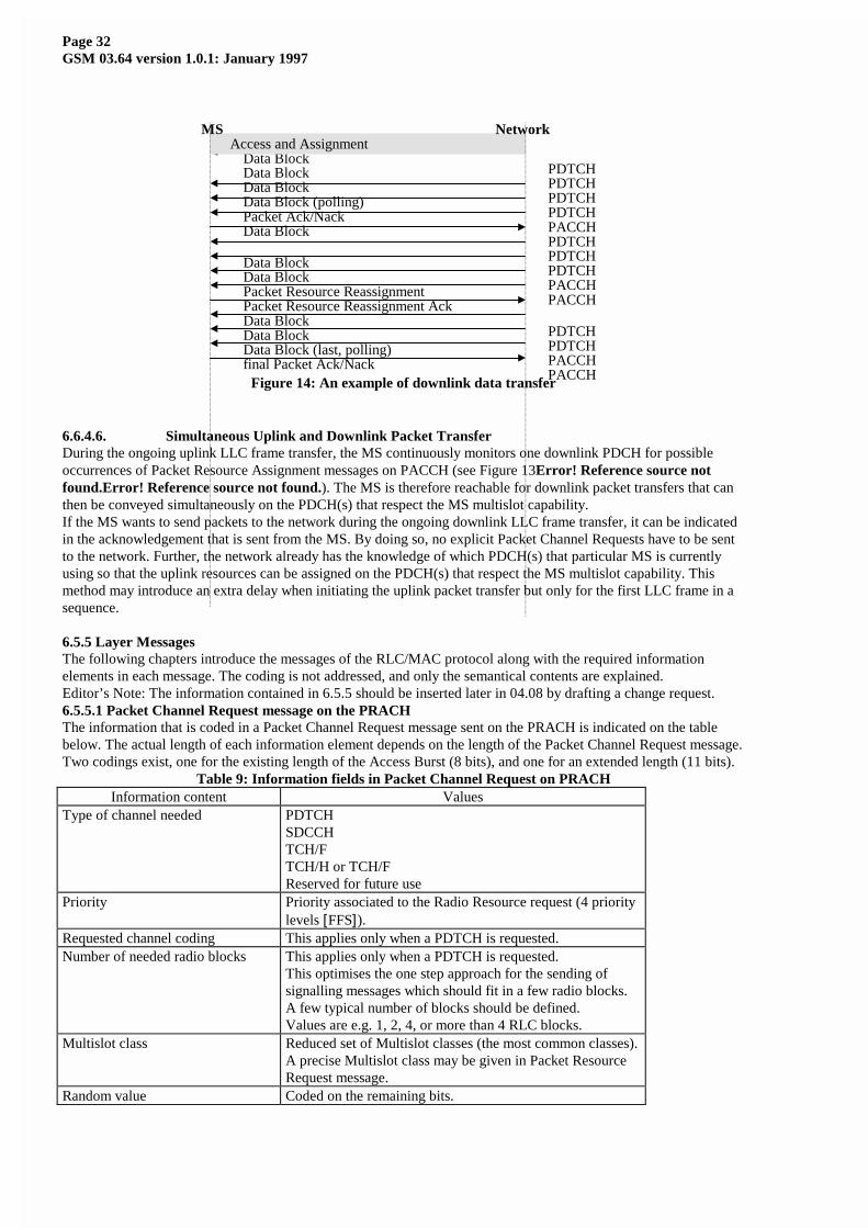
Page 32GSM 03.64 version 1.0.1: January 1997
Figure 14: An example of downlink data transfer
6.6.4.6. Simultaneous Uplink and Downlink Packet TransferDuring the ongoing uplink LLC frame transfer, the MS continuously monitors one downlink PDCH for possibleoccurrences of Packet Resource Assignment messages on PACCH (see Figure 13Error! Reference source notfound.Error! Reference source not found.). The MS is therefore reachable for downlink packet transfers that canthen be conveyed simultaneously on the PDCH(s) that respect the MS multislot capability.If the MS wants to send packets to the network during the ongoing downlink LLC frame transfer, it can be indicatedin the acknowledgement that is sent from the MS. By doing so, no explicit Packet Channel Requests have to be sentto the network. Further, the network already has the knowledge of which PDCH(s) that particular MS is currentlyusing so that the uplink resources can be assigned on the PDCH(s) that respect the MS multislot capability. Thismethod may introduce an extra delay when initiating the uplink packet transfer but only for the first LLC frame in asequence.
6.5.5 Layer MessagesThe following chapters introduce the messages of the RLC/MAC protocol along with the required informationelements in each message. The coding is not addressed, and only the semantical contents are explained.Editor’s Note: The information contained in 6.5.5 should be inserted later in 04.08 by drafting a change request.6.5.5.1 Packet Channel Request message on the PRACHThe information that is coded in a Packet Channel Request message sent on the PRACH is indicated on the tablebelow. The actual length of each information element depends on the length of the Packet Channel Request message.Two codings exist, one for the existing length of the Access Burst (8 bits), and one for an extended length (11 bits).
Table 9: Information fields in Packet Channel Request on PRACHInformation content Values
Type of channel needed PDTCHSDCCHTCH/FTCH/H or TCH/FReserved for future use
Priority Priority associated to the Radio Resource request (4 prioritylevels [FFS]).
Requested channel coding This applies only when a PDTCH is requested.Number of needed radio blocks This applies only when a PDTCH is requested.
This optimises the one step approach for the sending ofsignalling messages which should fit in a few radio blocks.A few typical number of blocks should be defined.Values are e.g. 1, 2, 4, or more than 4 RLC blocks.
Multislot class Reduced set of Multislot classes (the most common classes).A precise Multislot class may be given in Packet ResourceRequest message.
Random value Coded on the remaining bits.
Data Block
Packet Ack/Nack
Access and AssignmentMS Network
PDTCH
PACCH
Packet Resource ReassignmentPacket Resource Reassignment Ack
PACCHPACCH
PACCHfinal Packet Ack/Nack
Data BlockPDTCHData BlockPDTCHData Block (polling)PDTCH
Data BlockPDTCH
Data Block PDTCH
Data Block PDTCH
Data BlockPDTCHData BlockPDTCHData Block (last, polling)PACCH
Page 33GSM 03.64 version 1.0.1: January 1997
For each of the services, all the possible combinations of the parameters are identified in the technical specifications(e.g. the combination of channel needed and priority to use).For GPRS transfer, the priorities could be mapped on the GPRS QoS.6.7. Abnormal Cases in GPRS MS Ready State6.7.1. RLC/MAC-Error CausesThe abnormal cases of providing RLC/MAC-ERROR indication are similar to not succeeding LOCATIONUPDATING in GSM 03.22, 04.08, and 05.08. The reasons can be too far distance for Timing Advance (TA > 63)between MS and ordinary BSS, too low carrier/(Interference + Noise) (C/(I+N) < 9 dB) on BSS or MS, as well assome malfunction of BSS or MS.6.7.2. Packet Paging Request FailuresPacket Paging Request failures of PPCH shall be based on the Downlink Signalling Counter reaching to 0 (DSC=0)resulting in cell re-selection, i.e. putting down the upper PBCCH carrier in the MS NCELL list to the lowest on thelist for 30 s penalty time and resetting the DSC counter, see GSM 05.08.If four successive request cycles for all decoded PBCCH carriers in the MS NCELL list have failed, then go toPLMN search (see GSM 04.08).6.7.3. Packet Channel Request FailuresPacket Channel Request failures on PRACH by receiving no Packet Immediate Acknowledgement (ack or Nack)(within 5 s) on PAGCH for two successive random access attempts per NCELL shall result in cell re-selection, i.e.putting down the upper PBCCH carrier in the NCELL list to the lowest on the list for a 30 s penalty time, see alsoGSM 04.08.If four successive request cycles for all decoded PBCCH carriers in the MS NCELL list have failed, then go toPLMN search (see GSM 04.08).6.7.4. RLC Nack or Absence of ResponseWhen sending data blocks on PDTCH, an RLC Ack/Nack shall be responded on PACCH. If no responses have beenreceived or only RLC Nacks have been received for the maximum number of RLC re-transmissions (= 4), then theRLC retransmission data blocks and the remaining blocks shall continue after a cell re-selection procedure, as for thePPCH or the PRACH request failures above.6.7.5. PLMN SearchIf no suitable cell of the Home PLMN can be used for packet data transfer with cell re-selection procedures, then thestate PLMN SEARCH shall be entered as stated in GSM 04.08. If PLMN NOT ALLOWED is received orregistration failure is obtained on all PLMNs, the indicate RLC/MAC-ERROR and continue searching for PLMN,see GSM 03.22.6.8. Point to Multipoint Data TransferTransfer of Point To Multipoint - Multicast (PTM-M) messages is carried out without any ARQ on the RLC/MACand LLC layers.6.9. Gb Interface L2 and L1Layer 2 and Layer 1 for the Gb interface is described in GSM 03.60 [2].

Page 34GSM 03.64 version 1.0.1: January 1997
7. Bibliography1) ITU-T I.130, Method for the Characterization of Telecommunication Services
Supported by an ISDN2) ITU-T Q.65, Stage 2 of the Method for Characterization of the Services Supported by
an ISDN3) DIS 8886, OSI Data Link Service Definition4) DIS 10022, OSI Physical Service Definition5) ISO 10039, Medium Access Control Service Definition6) ISO 4335, HDLC Procedures7) ISO 7478, Multilink Procedures8) ISO 7498, OSI Basic Reference Model and Layer Service Conventions
Page 35GSM 03.64 version 1.0.1: January 1997
History
Document history
Date Status Comments
06.12.1996 0.1.0 Modified by Jari Hämäläinen.
Based on the 04.60 v.0.10.0. Specification numberchanged to GSM 03.64.
Major changes after 04.60 v.0.10.0:
LLC moved to 03.60. Improved MT transfer (Tdoc 135),Channel coding Tdoc 161, Cell Selection (Tdoc 158),USF definition (Tdoc 130), RR states (TdocSMG3G368), Multiframe (Tdoc 137), RLC abnormalcases (Tdoc 133), PRACH improvements and RLC/LLCack relation (Tdoc 138).
16.12.1996 0.1.1 Modified by ETSI: Changed reference from 04.60 to03.64 on page 7
Week 51/96 1.0.0 Acceptance by SMG2 with revisions by SMG2 GPRSadhoc.
Modified by Jari Hämäläinen.
Changes from SMG2 GPRS AdHoc 22-24.01.1997:
Tdoc 169/97 Definitions and abbreviations added, Tdoc190 multiframes and DRX improved, Tdoc 173 Codingschemes improved, 192 RLC/MAC temporary blockflow improvements, 189 Power Control procedures, 191Timing Advance, Tdoc 180 Network forced cell re-selection added. Editorial modifications to clean the text.
31.01.1997 1.0.1 Editorial modifications based on comments from PT80Vmembers.
Rapporteur contacts:
Jari Hämäläinen, Nokia Mobile Phones:
Tel.: +358 10 505 6896 - Fax: +358 10 505 6888 - Internet: [email protected]
This document is written in Microsoft Word for Windows 95 version 7.0.