Embed Size (px)
Citation preview
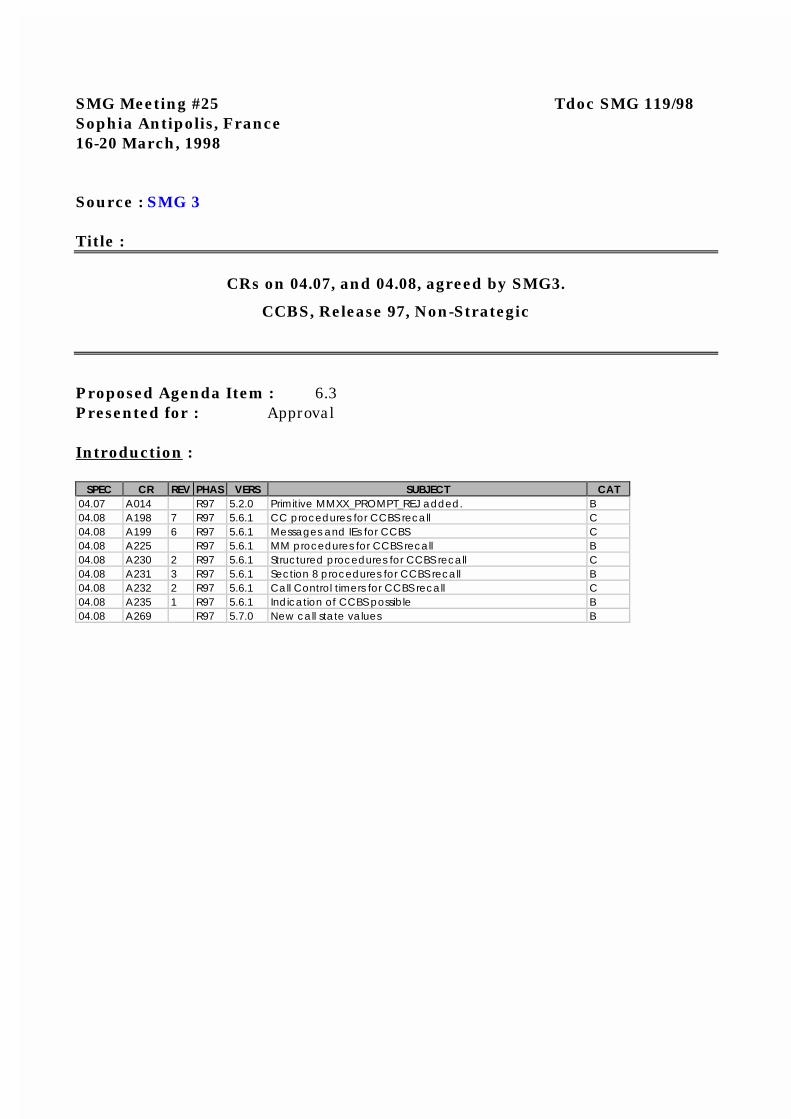
SMG Meeting #25 Tdoc SMG 119/98Sophia Antipolis, France16-20 March, 1998
Source : SMG 3
Title :
CRs on 04.07, and 04.08, agreed by SMG3.
CCBS, Release 97, Non-Strategic
Proposed Agenda Item : 6.3Presented for : Approval
Introduction :
SPEC CR REV PHAS VERS SUBJECT CAT04.07 A014 R97 5.2.0 Primitive MMXX_PROMPT_REJ added. B04.08 A198 7 R97 5.6.1 CC procedures for CCBS recall C04.08 A199 6 R97 5.6.1 Messages and IEs for CCBS C04.08 A225 R97 5.6.1 MM procedures for CCBS recall B04.08 A230 2 R97 5.6.1 Structured procedures for CCBS recall C04.08 A231 3 R97 5.6.1 Section 8 procedures for CCBS recall B04.08 A232 2 R97 5.6.1 Call Control timers for CCBS recall C04.08 A235 1 R97 5.6.1 Indication of CCBS possible B04.08 A269 R97 5.7.0 New call state values B
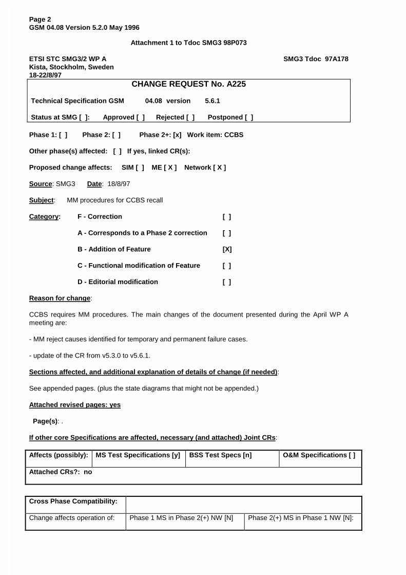
Page 2GSM 04.08 Version 5.2.0 May 1996
Attachment 1 to Tdoc SMG3 98P073
ETSI STC SMG3/2 WP A SMG3 Tdoc 97A178Kista, Stockholm, Sweden18-22/8/97
CHANGE REQUEST No. A225
Technical Specification GSM 04.08 version 5.6.1
Status at SMG [ ]: Approved [ ] Rejected [ ] Postponed [ ]
Phase 1: [ ] Phase 2: [ ] Phase 2+: [x] Work item: CCBS
Other phase(s) affected: [ ] If yes, linked CR(s):
Proposed change affects: SIM [ ] ME [ X ] Network [ X ]
Source: SMG3 Date: 18/8/97
Subject: MM procedures for CCBS recall
Category: F - Correction [ ]
A - Corresponds to a Phase 2 correction [ ]
B - Addition of Feature [X]
C - Functional modification of Feature [ ]
D - Editorial modification [ ]
Reason for change:
CCBS requires MM procedures. The main changes of the document presented during the April WP Ameeting are:
- MM reject causes identified for temporary and permanent failure cases.
- update of the CR from v5.3.0 to v5.6.1.
Sections affected, and additional explanation of details of change (if needed):
See appended pages. (plus the state diagrams that might not be appended.)
Attached revised pages: yes
Page(s): .
If other core Specifications are affected, necessary (and attached) Joint CRs:
Affects (possibly): MS Test Specifications [y] BSS Test Specs [n] O&M Specifications [ ]
Attached CRs?: no
Cross Phase Compatibility:
Change affects operation of: Phase 1 MS in Phase 2(+) NW [N] Phase 2(+) MS in Phase 1 NW [N]:

Change affects operation of: Phase 1 SIM in Phase 2(+) ME[N] Phase 2(+) SIM in Phase 1 ME [N]
Other comments: figure 4.1a is only updated in the paper copy.
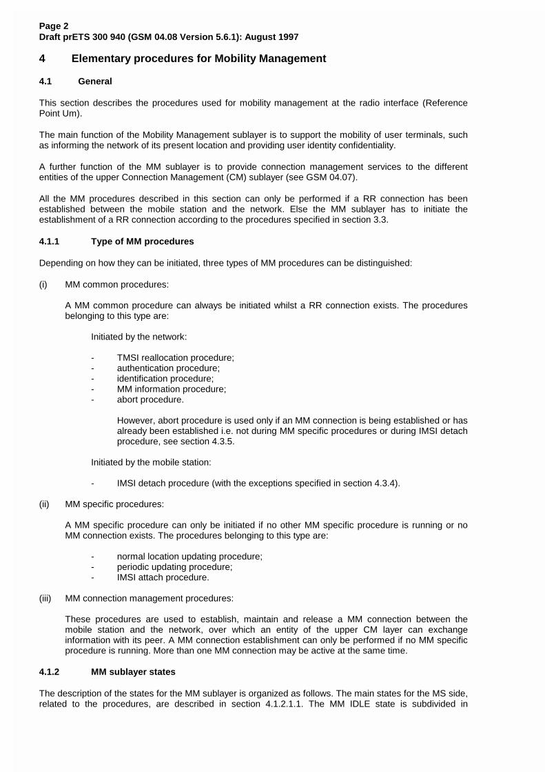
Page 2Draft prETS 300 940 (GSM 04.08 Version 5.6.1): August 1997
4 Elementary procedures for Mobility Management
4.1 General
This section describes the procedures used for mobility management at the radio interface (ReferencePoint Um).
The main function of the Mobility Management sublayer is to support the mobility of user terminals, suchas informing the network of its present location and providing user identity confidentiality.
A further function of the MM sublayer is to provide connection management services to the differententities of the upper Connection Management (CM) sublayer (see GSM 04.07).
All the MM procedures described in this section can only be performed if a RR connection has beenestablished between the mobile station and the network. Else the MM sublayer has to initiate theestablishment of a RR connection according to the procedures specified in section 3.3.
4.1.1 Type of MM procedures
Depending on how they can be initiated, three types of MM procedures can be distinguished:
(i) MM common procedures:
A MM common procedure can always be initiated whilst a RR connection exists. The proceduresbelonging to this type are:
Initiated by the network:
- TMSI reallocation procedure;- authentication procedure;- identification procedure;- MM information procedure;- abort procedure.
However, abort procedure is used only if an MM connection is being established or hasalready been established i.e. not during MM specific procedures or during IMSI detachprocedure, see section 4.3.5.
Initiated by the mobile station:
- IMSI detach procedure (with the exceptions specified in section 4.3.4).
(ii) MM specific procedures:
A MM specific procedure can only be initiated if no other MM specific procedure is running or noMM connection exists. The procedures belonging to this type are:
- normal location updating procedure;- periodic updating procedure;- IMSI attach procedure.
(iii) MM connection management procedures:
These procedures are used to establish, maintain and release a MM connection between themobile station and the network, over which an entity of the upper CM layer can exchangeinformation with its peer. A MM connection establishment can only be performed if no MM specificprocedure is running. More than one MM connection may be active at the same time.
4.1.2 MM sublayer states
The description of the states for the MM sublayer is organized as follows. The main states for the MS side,related to the procedures, are described in section 4.1.2.1.1. The MM IDLE state is subdivided in
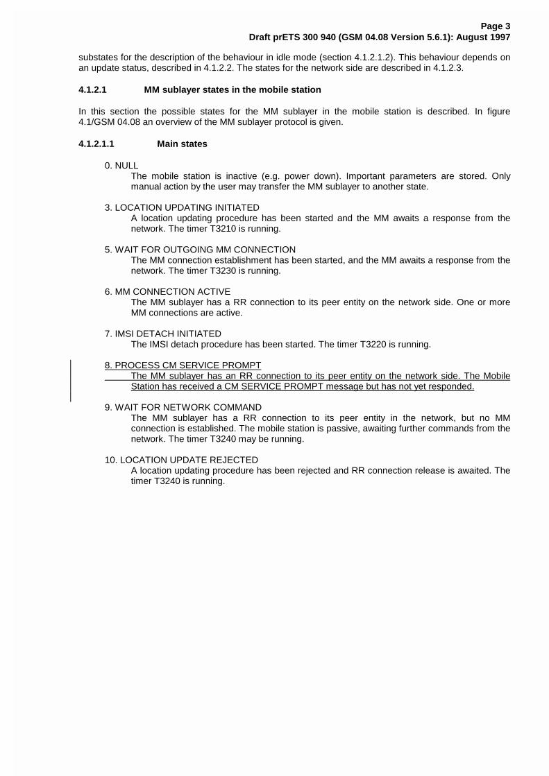
Page 3Draft prETS 300 940 (GSM 04.08 Version 5.6.1): August 1997
substates for the description of the behaviour in idle mode (section 4.1.2.1.2). This behaviour depends onan update status, described in 4.1.2.2. The states for the network side are described in 4.1.2.3.
4.1.2.1 MM sublayer states in the mobile station
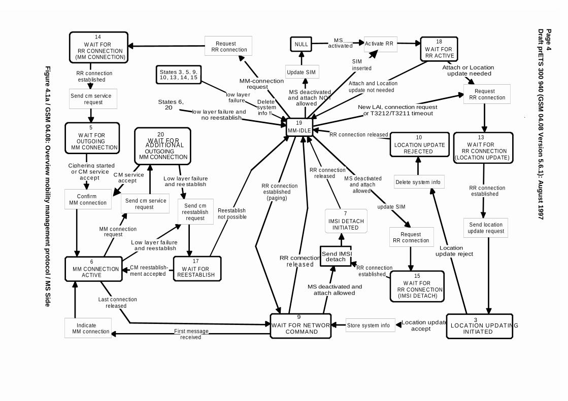
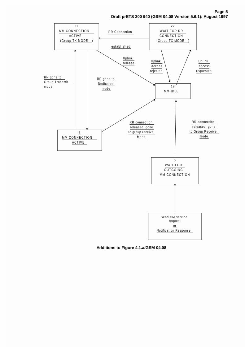
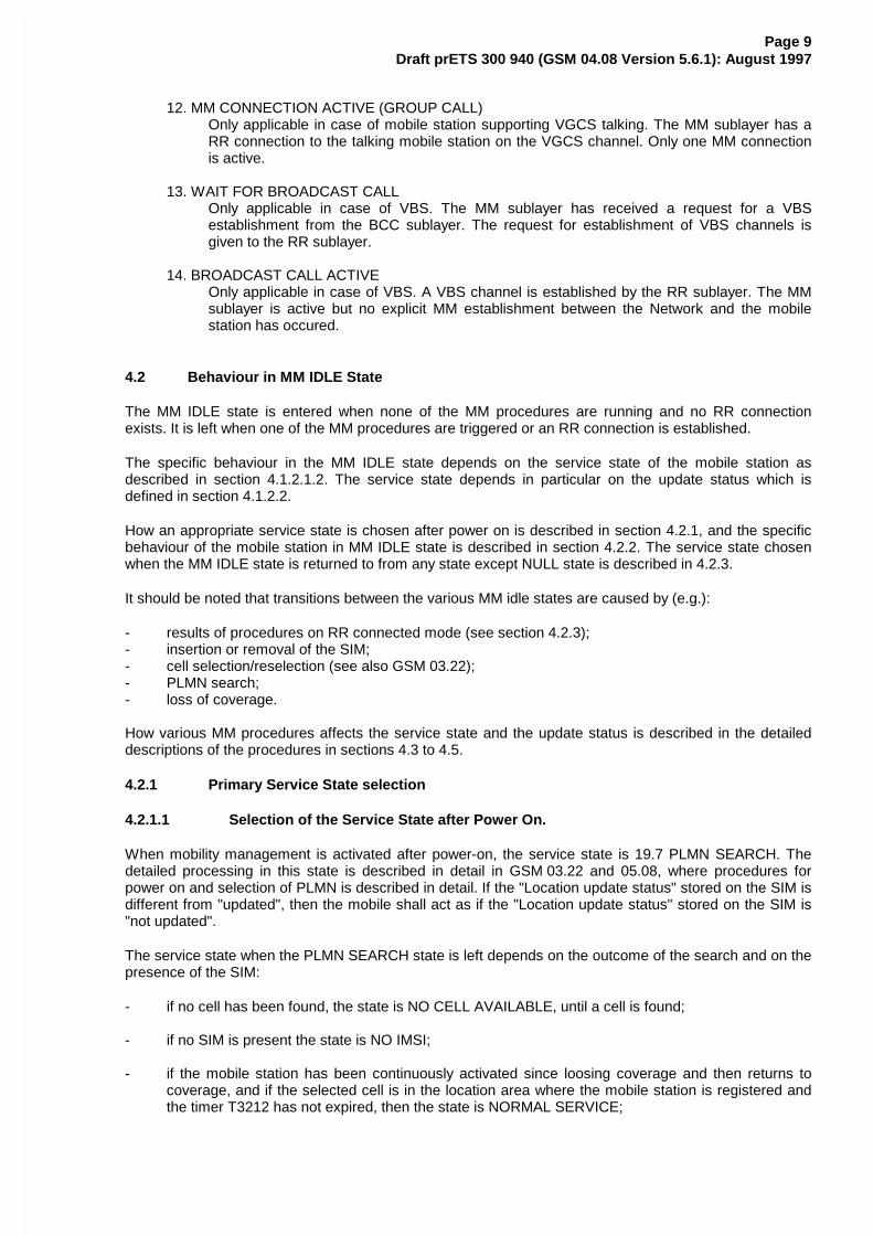
In this section the possible states for the MM sublayer in the mobile station is described. In figure4.1/GSM 04.08 an overview of the MM sublayer protocol is given.
4.1.2.1.1 Main states
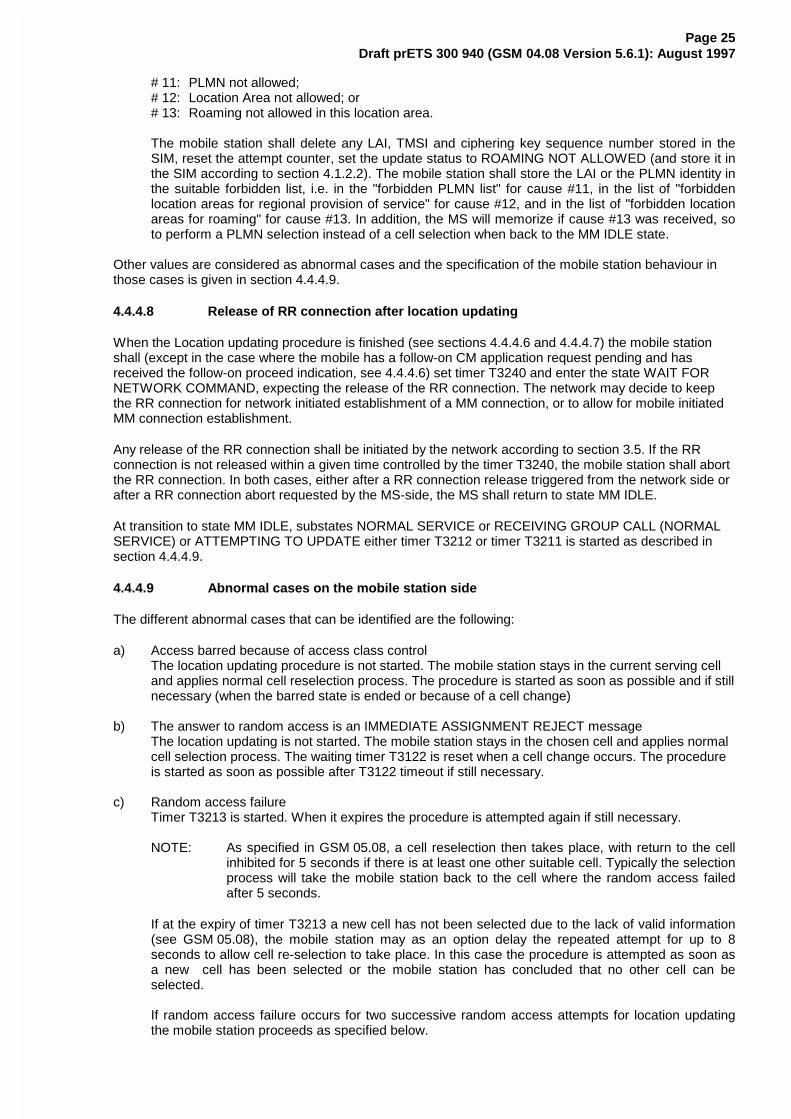
0. NULLThe mobile station is inactive (e.g. power down). Important parameters are stored. Onlymanual action by the user may transfer the MM sublayer to another state.
3. LOCATION UPDATING INITIATEDA location updating procedure has been started and the MM awaits a response from thenetwork. The timer T3210 is running.
5. WAIT FOR OUTGOING MM CONNECTIONThe MM connection establishment has been started, and the MM awaits a response from thenetwork. The timer T3230 is running.
6. MM CONNECTION ACTIVEThe MM sublayer has a RR connection to its peer entity on the network side. One or moreMM connections are active.
7. IMSI DETACH INITIATEDThe IMSI detach procedure has been started. The timer T3220 is running.
8. PROCESS CM SERVICE PROMPT The MM sublayer has an RR connection to its peer entity on the network side. The Mobile
Station has received a CM SERVICE PROMPT message but has not yet responded.
9. WAIT FOR NETWORK COMMANDThe MM sublayer has a RR connection to its peer entity in the network, but no MMconnection is established. The mobile station is passive, awaiting further commands from thenetwork. The timer T3240 may be running.
10. LOCATION UPDATE REJECTEDA location updating procedure has been rejected and RR connection release is awaited. Thetimer T3240 is running.
Pag
e 4D
raft prE
TS
300 940 (GS
M 04.08 V
ersion
5.6.1): Au
gu
st 1997
Attach or Locationupdate needed
Attach and Locationupdate not needed
RR connectionestablished
Locationupdate reject
Location updateaccept
RR connection released
New LAI, connection requestor T3212/T3211 timeout
MS deactivatedand attach NOT
allowed
MM-connectionrequest
RR connectionestab lished
First messagereceived
Last connec tionreleased
Low layer fa ilureand reestablish
RR connec tionestablished
(paging)
MS deactivatedand attach
allowed
MS deactivated andattach allowed
RR connec tionestablished
RR connec tionreleased
low layerfailure
Low layer failureand ree stablish
Reestablishnot possible
update SIM
States 6,20
Send IMSIdetach
RequestRR connec tion
Send cmreestablish
request
IndicateMM connection
Send cm servicerequest
Confi rmMM connec tion
Send cm servicerequest
RequestRR connec tion
Update SIM
Store system info
Delete system info
Send locationupdate request
RequestRR connection
Ac tivate RR
IMSI DETACHINITIATED
7
W AIT FORREESTABLISH
17MM CONNECTION
ACTIVE
6
W AIT FORRR CONNE CTION(IMSI DETACH)
15
W AIT FOROUTGOING
MM CONNEC TION
5
W AIT FORRR CONNECTION
(MM CONNECTION)
14
LOCATION UPDATINGINITIATED
3
LOCATION UPDATEREJE CTED
10W AIT FOR
RR CONNECTION(LOCATION UPDATE)
13
W AIT FORRR ACTIVE
18NULL
States 3, 5, 9,10, 13 , 14, 15
CM reestablish-ment accepted
WAIT FOR NETWORKCOMMAND
9
SIMinserted
MSactivated
Deletesysteminfo !!low layer fa ilure and
no reestablish
CM serviceaccept
MM-IDLE19
Ciphering startedor CM service
accept
MM connectionrequest
W AIT FO RADDITIONALOUTGOING
MM CONNECTION
20
RR connectionre le a s e d
.
Fig
ure 4.1a / G
SM
04.08: Overview
mo
bility m
anag
emen
t pro
toco
l / MS
Sid
e
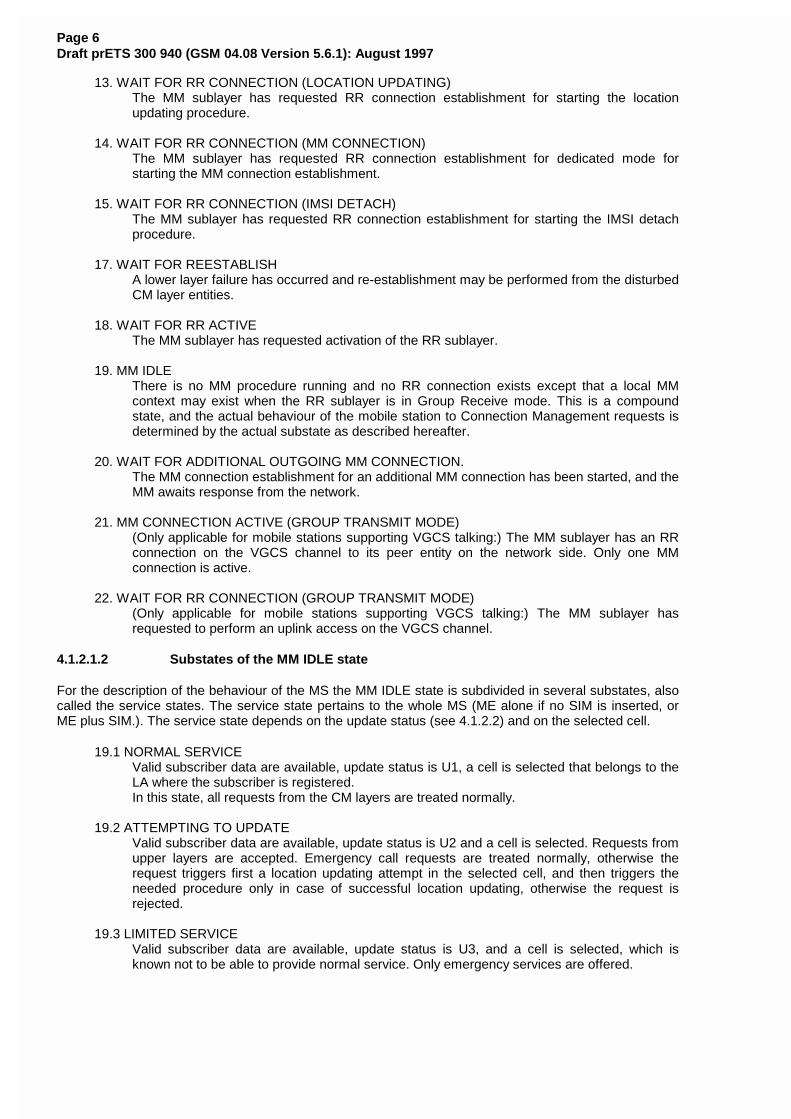
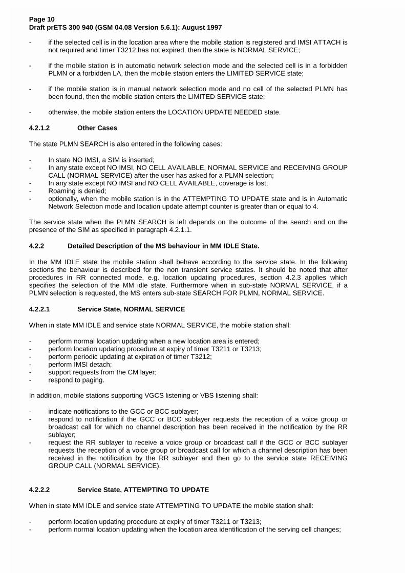
Page 5Draft prETS 300 940 (GSM 04.08 Version 5.6.1): August 1997
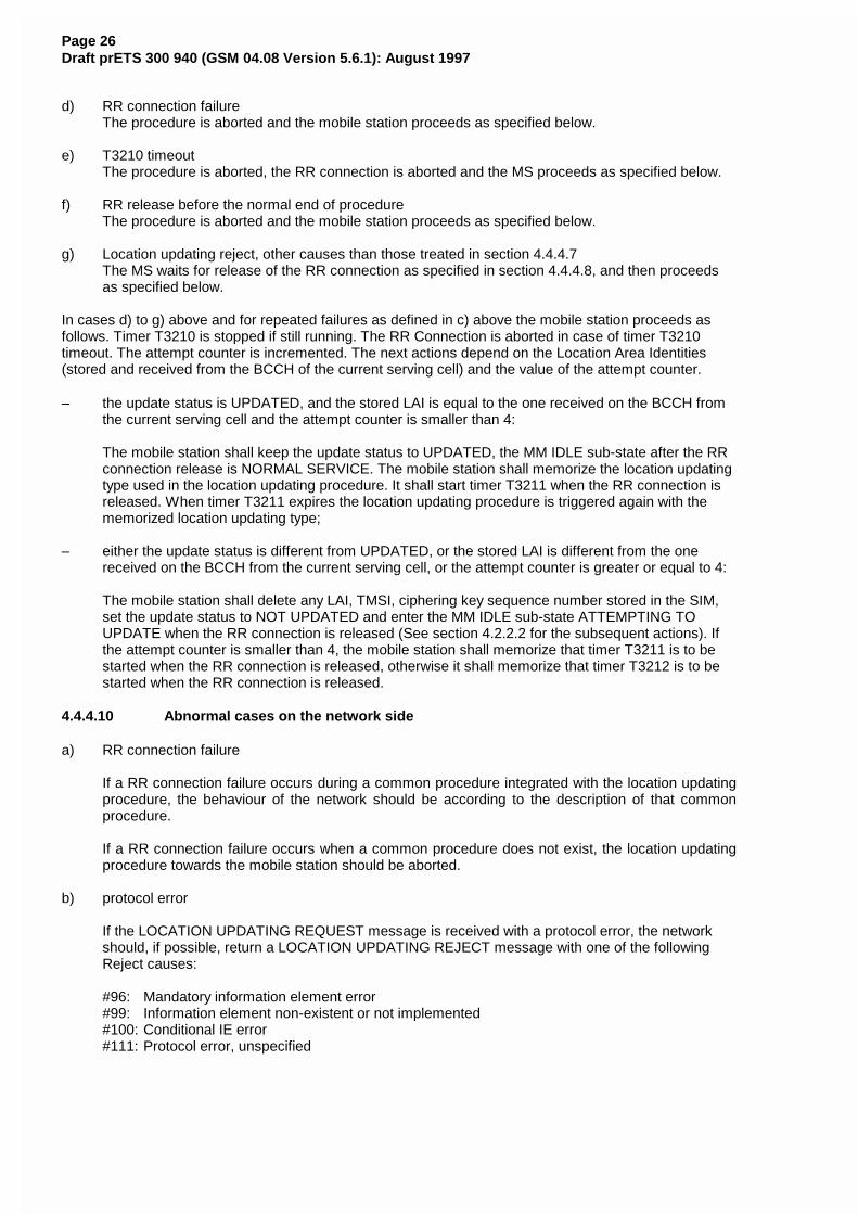
RR gone toGroup Transmi tmode
21M M C O N N E C T I O N
ACTIVE( Group TX MODE )
22WAIT FOR RRC O N N E C T I O N
( Group TX MODE )
RR Connect ion
established
6M M C O N N E C T I O N
ACTIVE
19MM- IDLE
5W A I T F O R
O U T G O I N GM M C O N N E C T I O N
Send CM serv icerequest
orNot i f icat ion Response
RR gone toDedicated
mode
Upl inkrelease Upl ink
accessrejected
Upl inkaccess
requested
RR connect ionreleased, gone
to group receiveMode
RR connect ionreleased, gone
to Group Receivemode
Additions to Figure 4.1.a/GSM 04.08
Page 6Draft prETS 300 940 (GSM 04.08 Version 5.6.1): August 1997
13. WAIT FOR RR CONNECTION (LOCATION UPDATING)The MM sublayer has requested RR connection establishment for starting the locationupdating procedure.
14. WAIT FOR RR CONNECTION (MM CONNECTION)The MM sublayer has requested RR connection establishment for dedicated mode forstarting the MM connection establishment.
15. WAIT FOR RR CONNECTION (IMSI DETACH)The MM sublayer has requested RR connection establishment for starting the IMSI detachprocedure.
17. WAIT FOR REESTABLISHA lower layer failure has occurred and re-establishment may be performed from the disturbedCM layer entities.
18. WAIT FOR RR ACTIVEThe MM sublayer has requested activation of the RR sublayer.
19. MM IDLEThere is no MM procedure running and no RR connection exists except that a local MMcontext may exist when the RR sublayer is in Group Receive mode. This is a compoundstate, and the actual behaviour of the mobile station to Connection Management requests isdetermined by the actual substate as described hereafter.
20. WAIT FOR ADDITIONAL OUTGOING MM CONNECTION.The MM connection establishment for an additional MM connection has been started, and theMM awaits response from the network.
21. MM CONNECTION ACTIVE (GROUP TRANSMIT MODE)(Only applicable for mobile stations supporting VGCS talking:) The MM sublayer has an RRconnection on the VGCS channel to its peer entity on the network side. Only one MMconnection is active.
22. WAIT FOR RR CONNECTION (GROUP TRANSMIT MODE)(Only applicable for mobile stations supporting VGCS talking:) The MM sublayer hasrequested to perform an uplink access on the VGCS channel.
4.1.2.1.2 Substates of the MM IDLE state
For the description of the behaviour of the MS the MM IDLE state is subdivided in several substates, alsocalled the service states. The service state pertains to the whole MS (ME alone if no SIM is inserted, orME plus SIM.). The service state depends on the update status (see 4.1.2.2) and on the selected cell.
19.1 NORMAL SERVICEValid subscriber data are available, update status is U1, a cell is selected that belongs to theLA where the subscriber is registered.In this state, all requests from the CM layers are treated normally.
19.2 ATTEMPTING TO UPDATEValid subscriber data are available, update status is U2 and a cell is selected. Requests fromupper layers are accepted. Emergency call requests are treated normally, otherwise therequest triggers first a location updating attempt in the selected cell, and then triggers theneeded procedure only in case of successful location updating, otherwise the request isrejected.
19.3 LIMITED SERVICEValid subscriber data are available, update status is U3, and a cell is selected, which isknown not to be able to provide normal service. Only emergency services are offered.
Page 7Draft prETS 300 940 (GSM 04.08 Version 5.6.1): August 1997
19.4 NO IMSINo valid subscriber data (no SIM, or the SIM is not considered valid by the ME), and a cell isselected. Only emergency services are offered.
19.5 NO CELL AVAILABLENo cell can be selected. This state is entered after a first intensive search failed (state 19.7).Cells are searched at a low rhythm. No services are offered.
19.6 LOCATION UPDATE NEEDEDValid subscriber data are available, and for some reason a location updating must be doneas soon as possible (for instance update status is U1 but the selected cell is not in theregistered LA, or the timer has expired, ...). This state is usually of no duration, but can last,e.g., in the case of access class blocking.
19.7 PLMN SEARCHThe mobile station is searching for PLMNs, and the conditions for state 19.8 are not met.This state is ended when either a cell is selected (the new state is 19.1, 19.3 or 19.6), orwhen it is concluded that no cell is available for the moment (the new state is 19.5).
19.8 PLMN SEARCH, NORMAL SERVICEValid subscriber data are available, update status is U1, a cell is selected which belongs tothe LA where the subscriber is registered, and the mobile station is searching for PLMNs.This state is ended when either a cell is selected (the new state is 19.1, 19.3 or 19.6), orwhen it is concluded that no cell is available for the moment (the new state is 19.5).
19.9 RECEIVING GROUP CALL (NORMAL SERVICE)Only applicable for mobile stations supporting VGCS listening or VBS listening. Validsubscriber data are available, update status is U1, a VGCS channel or VBS channel isreceived in a cell that belongs to the LA where the subscriber is registered.In this state, only requests from the GCC or BCC layers are treated.
19.10 RECEIVING GROUP CALL (LIMITED SERVICE)Only applicable for mobile stations supporting VGCS listening or VBS listening. Validsubscriber data are available, update status is U3, a VGCS channel or VBS channel isreceived in a cell which is known not to be able to provide normal service.In this state, only requests from the GCC or BCC layers for the reception of VGCS or VBScalls are treated and group call emergency services are offered.
4.1.2.2 The update Status
In parallel with the sublayer states described in section 4.1.2.1 and which control the MM sublayerprotocol, an update status exists.
The update status pertains to a specific subscriber embodied by a SIM. This status is defined even whenthe subscriber is not activated (SIM removed or connected to a switched-off ME). It is stored in a nonvolatile memory in the SIM. The update status is changed only as a result of a location updating procedureattempt (with the exception of an authentication failure and of some cases of CM service rejection).
U1 UPDATEDThe last location updating attempt was successful (correct procedure outcome, and theanswer was acceptance from the network). With this status, the SIM contains also the LAI ofthe LA where the subscriber is registered, and possibly valid TMSI, ciphering key andciphering key sequence number. The "Location update status" stored on the SIM shall be"updated".
U2 NOT UPDATEDThe last location updating attempt made failed procedurally (no significant answer wasreceived from the network, including the cases of failures or congestion inside the network).
For this status, the SIM does not contain any valid LAI, TMSI, ciphering key or ciphering keysequence number. For compatibility reasons, all these fields must be set to the "deleted"value at the moment the status is set to NOT UPDATED. However the presence of other
Page 8Draft prETS 300 940 (GSM 04.08 Version 5.6.1): August 1997
values shall not be considered an error by the mobile station. The "Location update status"stored on the SIM shall be "not updated".
U3 ROAMING NOT ALLOWEDThe last location updating attempt run correctly, but the answer from the network wasnegative (because of roaming or subscription restrictions).
For this status, the SIM does not contain any valid LAI, TMSI, ciphering key or ciphering keysequence number. For compatibility reasons, all these fields must be set to the "deleted"value at the moment the status is set to ROAMING NOT ALLOWED. However the presenceof other values shall not be considered an error by the mobile station. The "Location updatestatus" stored on the SIM shall be "Location Area not allowed".
4.1.2.3 MM sublayer states on the network side
1. IDLEThe MM sublayer is not active except possibly when the RR sublayer is in Group Receivemode.
2. WAIT FOR RR CONNECTIONThe MM sublayer has received a request for MM connection establishment from the CMlayer. A RR connection to the mobile station is requested from the RR sublayer (i.e. paging isperformed).
3. MM CONNECTION ACTIVEThe MM sublayer has a RR connection to a mobile station. One or more MM connections areactive.
4. IDENTIFICATION INITIATEDThe identification procedure has been started by the network. The timer T3270 is running.
5. AUTHENTICATION INITIATEDThe authentication procedure has been started by the network. The timer T3260 is running.
6. TMSI REALLOCATION INITIATEDThe TMSI reallocation procedure has been started by the network. The timer T3250 isrunning.
7. CIPHERING MODE INITIATEDThe cipher mode setting procedure has been requested to the RR sublayer.
8a. WAIT FOR MOBILE ORIGINATED MM CONNECTIONA CM SERVICE REQUEST message is received and processed, and the MM sublayerawaits the "opening message" of the MM connection.
8b. WAIT FOR NETWORK ORIGINATED MM CONNECTION A CM SERVICE PROMPT message has been sent by the network and the MM sublayer
awaits the “opening message” of the MM connection.
9. WAIT FOR REESTABLISHMENTThe RR connection to a mobile station with one or more active MM connection has been lost.The network awaits a possible re-establishment request from the mobile station.
10. WAIT OF A GROUP CALLOnly applicable in case for mobile station supporting VGCS talking. The MM sublayer hasreceived a request for establishing a VGCS from the GCC sublayer. The request forestablishing a VGCS channels is given to the RR sublayer.
11. GROUP CALL ACTIVEOnly applicable in case of mobile station supporting VGCS talking. A VGCS channel isestablished by the RR sublayer. An RR connection to the talking mobile station can beestablished by the RR sublayer on the VGCS channel. The MM sublayer is active but nosending of MM message between the network and the mobile station has occured.
Page 9Draft prETS 300 940 (GSM 04.08 Version 5.6.1): August 1997
12. MM CONNECTION ACTIVE (GROUP CALL)Only applicable in case of mobile station supporting VGCS talking. The MM sublayer has aRR connection to the talking mobile station on the VGCS channel. Only one MM connectionis active.
13. WAIT FOR BROADCAST CALLOnly applicable in case of VBS. The MM sublayer has received a request for a VBSestablishment from the BCC sublayer. The request for establishment of VBS channels isgiven to the RR sublayer.
14. BROADCAST CALL ACTIVEOnly applicable in case of VBS. A VBS channel is established by the RR sublayer. The MMsublayer is active but no explicit MM establishment between the Network and the mobilestation has occured.
4.2 Behaviour in MM IDLE State
The MM IDLE state is entered when none of the MM procedures are running and no RR connectionexists. It is left when one of the MM procedures are triggered or an RR connection is established.
The specific behaviour in the MM IDLE state depends on the service state of the mobile station asdescribed in section 4.1.2.1.2. The service state depends in particular on the update status which isdefined in section 4.1.2.2.
How an appropriate service state is chosen after power on is described in section 4.2.1, and the specificbehaviour of the mobile station in MM IDLE state is described in section 4.2.2. The service state chosenwhen the MM IDLE state is returned to from any state except NULL state is described in 4.2.3.
It should be noted that transitions between the various MM idle states are caused by (e.g.):
- results of procedures on RR connected mode (see section 4.2.3);- insertion or removal of the SIM;- cell selection/reselection (see also GSM 03.22);- PLMN search;- loss of coverage.
How various MM procedures affects the service state and the update status is described in the detaileddescriptions of the procedures in sections 4.3 to 4.5.
4.2.1 Primary Service State selection
4.2.1.1 Selection of the Service State after Power On.
When mobility management is activated after power-on, the service state is 19.7 PLMN SEARCH. Thedetailed processing in this state is described in detail in GSM 03.22 and 05.08, where procedures forpower on and selection of PLMN is described in detail. If the "Location update status" stored on the SIM isdifferent from "updated", then the mobile shall act as if the "Location update status" stored on the SIM is"not updated".
The service state when the PLMN SEARCH state is left depends on the outcome of the search and on thepresence of the SIM:
- if no cell has been found, the state is NO CELL AVAILABLE, until a cell is found;
- if no SIM is present the state is NO IMSI;
- if the mobile station has been continuously activated since loosing coverage and then returns tocoverage, and if the selected cell is in the location area where the mobile station is registered andthe timer T3212 has not expired, then the state is NORMAL SERVICE;
Page 10Draft prETS 300 940 (GSM 04.08 Version 5.6.1): August 1997
- if the selected cell is in the location area where the mobile station is registered and IMSI ATTACH isnot required and timer T3212 has not expired, then the state is NORMAL SERVICE;
- if the mobile station is in automatic network selection mode and the selected cell is in a forbiddenPLMN or a forbidden LA, then the mobile station enters the LIMITED SERVICE state;
- if the mobile station is in manual network selection mode and no cell of the selected PLMN hasbeen found, then the mobile station enters the LIMITED SERVICE state;
- otherwise, the mobile station enters the LOCATION UPDATE NEEDED state.
4.2.1.2 Other Cases
The state PLMN SEARCH is also entered in the following cases:
- In state NO IMSI, a SIM is inserted;- In any state except NO IMSI, NO CELL AVAILABLE, NORMAL SERVICE and RECEIVING GROUP
CALL (NORMAL SERVICE) after the user has asked for a PLMN selection;- In any state except NO IMSI and NO CELL AVAILABLE, coverage is lost;- Roaming is denied;- optionally, when the mobile station is in the ATTEMPTING TO UPDATE state and is in Automatic
Network Selection mode and location update attempt counter is greater than or equal to 4.
The service state when the PLMN SEARCH is left depends on the outcome of the search and on thepresence of the SIM as specified in paragraph 4.2.1.1.
4.2.2 Detailed Description of the MS behaviour in MM IDLE State.
In the MM IDLE state the mobile station shall behave according to the service state. In the followingsections the behaviour is described for the non transient service states. It should be noted that afterprocedures in RR connected mode, e.g. location updating procedures, section 4.2.3 applies whichspecifies the selection of the MM idle state. Furthermore when in sub-state NORMAL SERVICE, if aPLMN selection is requested, the MS enters sub-state SEARCH FOR PLMN, NORMAL SERVICE.
4.2.2.1 Service State, NORMAL SERVICE
When in state MM IDLE and service state NORMAL SERVICE, the mobile station shall:
- perform normal location updating when a new location area is entered;- perform location updating procedure at expiry of timer T3211 or T3213;- perform periodic updating at expiration of timer T3212;- perform IMSI detach;- support requests from the CM layer;- respond to paging.
In addition, mobile stations supporting VGCS listening or VBS listening shall:
- indicate notifications to the GCC or BCC sublayer;- respond to notification if the GCC or BCC sublayer requests the reception of a voice group or
broadcast call for which no channel description has been received in the notification by the RRsublayer;
- request the RR sublayer to receive a voice group or broadcast call if the GCC or BCC sublayerrequests the reception of a voice group or broadcast call for which a channel description has beenreceived in the notification by the RR sublayer and then go to the service state RECEIVINGGROUP CALL (NORMAL SERVICE).
4.2.2.2 Service State, ATTEMPTING TO UPDATE
When in state MM IDLE and service state ATTEMPTING TO UPDATE the mobile station shall:
- perform location updating procedure at expiry of timer T3211 or T3213;- perform normal location updating when the location area identification of the serving cell changes;
Page 11Draft prETS 300 940 (GSM 04.08 Version 5.6.1): August 1997
- if entry into this state was caused by c) or d) or f) (with cause different from "abnormal release,unspecified") or g) (with cause "retry upon entry into a new cell") of section 4.4.4.9, then locationupdating shall be performed when a new cell is entered;
- if entry into this state was caused by e) or f) (with cause "abnormal release, unspecified") or g) (withcause different from "retry upon entry into a new cell") of section 4.4.4.9, then location updatingshall not be performed because a new cell is entered;
- perform normal location updating at expiry of timer T3212;- not perform IMSI detach;- support request for emergency calls;- use other request from CM layer as triggering of normal location updating procedure (if the location
updating procedure is successful, then the request for MM connection is accepted, seesection 4.5.1);
- respond to paging (with IMSI).
In addition, mobile stations supporting VGCS listening or VBS listening shall:
- indicate notifications to the GCC or BCC sublayer for which a channel description has beenreceived in the notification by the RR sublayer;
- reject requests of the GCC or BCC sublayer to respond to notifications for which no channeldescription has been received in the notification by the RR sublayer;
- request the RR sublayer to receive a voice group or broadcast call if the GCC or BCC sublayerrequests the reception of a voice group or broadcast call for which a channel description has beenreceived in the notification by the RR sublayer and then go to the service state RECEIVINGGROUP CALL (LIMITED SERVICE).
4.2.2.3 Service State, LIMITED SERVICE
When in state MM IDLE and service state LIMITED SERVICE the mobile station shall:
- not perform periodic updating;- not perform IMSI detach;- reject any requests from CM entities for MM connections except for emergency calls;- perform normal location updating when a cell is entered which may provide normal service
(e.g. location area not in one of the forbidden LAI lists.);- it may respond to paging (with IMSI).
In addition, mobile stations supporting VGCS listening or VBS listening shall:
- indicate notifications to the GCC or BCC sublayer for which a channel description has beenreceived in the notification by the RR sublayer;
- reject requests of the GCC or BCC sublayer to respond to notifications for which no channeldescription has been received in the notification by the RR sublayer;
- request the RR sublayer to receive a voice group or broadcast call if the GCC or BCC sublayerrequests the reception of a voice group or broadcast call for which a channel description has beenreceived in the notification by the RR sublayer and then go to the service state RECEIVINGGROUP CALL (LIMITED SERVICE).
4.2.2.4 Service State, NO IMSI
When in state MM IDLE and service state NO IMSI the mobile station shall (see section 3.2, GSM 03.22and GSM 05.08):
- not start any normal location updating attempt;- not perform periodic updating;- not perform IMSI detach if powered down;- reject any request from CM entities for MM connections except for emergency calls;- not respond to paging;- only perform default cell selection.
In addition, mobile stations supporting VGCS listening or VBS listening shall:
- not indicate notifications to the GCC or BCC layer.
Page 12Draft prETS 300 940 (GSM 04.08 Version 5.6.1): August 1997
4.2.2.5 Service State, SEARCH FOR PLMN, NORMAL SERVICE
When in state MM IDLE and service state SEARCH FOR PLMN, NORMAL SERVICE the mobile stationshall:
- if timer T3211 or T3213 expires in this state perform a location updating procedure at the latest ifand when back to NORMAL SERVICE state and if the cell is not changed;
- if timer T3212 expires in this state perform a periodic location updating procedure at the latest if andwhen back to NORMAL SERVICE state;
- perform IMSI detach;- support requests from the CM layer;- listen as far as possible to paging, and respond.
In addition, mobile stations supporting VGCS listening or VBS listening shall:
- listen as far as possible to notifications and indicate notifications to the GCC or BCC layer;- respond to notification if the GCC or BCC sublayer requests the reception of a voice group or
broadcast call for which no channel description has been received in the notification by the RRsublayer;
- request the RR sublayer to receive a voice group or broadcast call if the GCC or BCC sublayerrequests the reception of a voice group or broadcast call for which a channel description has beenreceived in the notification by the RR sublayer.
4.2.2.6 Service State, SEARCH FOR PLMN
When in state MM IDLE and service state SEARCH FOR PLMN the mobile station shall:
- not start any normal location updating attempt;- not perform periodic updating;- not perform IMSI detach if powered down;- reject any request from CM entities for MM connections except emergency calls;- not respond to paging.
4.2.2.7 Service State, RECEIVING GROUP CALL (NORMAL SERVICE)
Only applicable for mobile stations supporting VGCS listening or VBS listening:
When in state MM IDLE and service state RECEIVING GROUP CALL (NORMAL SERVICE), the mobilestation shall:
- perform normal location updating when a new location area is entered;- perform location updating procedure at expiry of timer T3211 or T3213;- perform periodic updating at expiration of timer T3212;- perform IMSI detach;- support requests from the GCC or BCC layers;- indicate notifications or paging informations to the GCC or BCC layer;- respond to notification if the GCC or BCC sublayer requests the reception of a voice group or
broadcast call for which no channel description has been received in the notification by the RRsublayer;
- request the RR sublayer to receive another voice group or broadcast call if the GCC or BCCsublayer requests the reception of a voice group or broadcast call for which a channel descriptionhas been received in the notification by the RR sublayer.
4.2.2.8 Service State, RECEIVING GROUP CALL (LIMITED SERVICE)
Only applicable for mobile stations supporting VGCS listening or VBS listening:
When in state MM IDLE and service state RECEIVING GROUP CALL (LIMITED SERVICE), the mobilestation shall:
- not perform periodic updating;- not perform IMSI detach;- reject any requests from CM entities for MM connections except for emergency calls;
Page 13Draft prETS 300 940 (GSM 04.08 Version 5.6.1): August 1997
- perform normal location updating when a cell is entered which may provide normal service(e.g. location area not in one of the forbidden LAI lists.);
- it may respond to paging (with IMSI);- indicate notifications to the GCC or BCC sublayer for which a channel description has been
received in the notification by the RR sublayer;- reject requests of the GCC or BCC sublayer to respond to notifications for which no channel
description has been received in the notification by the RR sublayer;- request the RR sublayer to receive a voice group or broadcast call if the GCC or BCC sublayer
requests the reception of a voice group or broadcast call for which a channel description has beenreceived in the notification by the RR sublayer and then go to the service state RECEIVINGGROUP CALL (LIMITED SERVICE).
4.2.3 Service state when back to state MM IDLE from another state
When returning to MM IDLE, e.g., after a location updating procedure, the mobile station selects the cellas specified in GSM 03.22. With one exception, this is a normal cell selection.
If this return to idle state is not subsequent to a location updating procedure terminated with reception ofcause "Roaming not allowed in this location area" the service state depends on the result of the cellselection procedure, on the update status of the mobile station, on the location data stored in the mobilestation and on the presence of the SIM:
- if no cell has been found, the state is NO CELL AVAILABLE, until a cell is found;
- if no SIM is present, or if the inserted SIM is considered invalid by the MS, the state is NO IMSI;
- if the selected cell is in the location area where the MS is registered, then the state is NORMALSERVICE; it shall be noted that this also includes an abnormal case described in paragraph 4.4.4.9;
- (Only applicable for mobile stations supporting VGCS listening or VBS listening.) if the mobilestations was in the service state RECEIVING GROUP CALL (NORMAL SERVICE) or RECEIVINGGROUP CALL (LIMITED SERVICE) before the location updating procedure and the selected cell isin the location area where the mobile station is registered, then the state is RECEIVING GROUPCALL (NORMAL SERVICE);
- if the selected cell is in a location area where the mobile station is not registered but in which theMS is allowed to attempt a location update, then the state is LOCATION UPDATE NEEDED;
- if the selected cell is in a location area where the mobile station is not allowed to attempt a locationupdate, then the state is LIMITED SERVICE;
- (Only applicable for MSs supporting VGCS listening or VBS listening.) if the MSs was in the servicestate RECEIVING GROUP CALL (NORMAL SERVICE) or RECEIVING GROUP CALL (LIMITEDSERVICE) before the location updating procedure and the selected cell is in the location areawhere the MS is not allowed to attempt a location update, then the state is RECEIVING GROUPCALL (LIMITED SERVICE);
- after some abnormal cases occurring during an unsuccessful location updating procedure, asdescribed in paragraph 4.4.4.9, the state is ATTEMPTING TO UPDATE.
In case of a return from a location updating procedure to which was answered "Roaming not allowed inthis location area", the service state PLMN SEARCH is entered as specified in section 4.2.1.2.
4.3 MM common procedures
As described above, a MM common procedure can be initiated at any time whilst a RR connection existsbetween the network an the mobile station.
4.3.1 TMSI reallocation procedure
The purpose of the TMSI reallocation procedure is to provide identity confidentiality , i.e. to protect a useragainst being identified and located by an intruder (see GSM 02.09 and 03.20).
Page 14Draft prETS 300 940 (GSM 04.08 Version 5.6.1): August 1997
If the identity confidentiality service is applied for an IMSI, a Temporary Mobile Subscriber Identity (TMSI)is used for identification within the radio interface signalling procedures.
The structure of the TMSI is specified in GSM 03.03. The TMSI has significance only within a locationarea. Outside the location area it has to be combined with the Location Area Identifier (LAI) to provide foran unambiguous identity.
Usually the TMSI reallocation is performed at least at each change of a location area. (Such choices areleft to the network operator).
The reallocation of a TMSI can be performed either by a unique procedure defined in this section orimplicitly by a location updating procedure using the TMSI. The implicit reallocation of a TMSI is describedtogether with that procedure.
If a TMSI provided by a mobile station is unknown in the network e.g. due to a data base failure, thenetwork may require the mobile station to provide its International Mobile Subscriber Identity (IMSI). In thiscase the identification procedure (see section 4.3.3) should be used before the TMSI reallocationprocedure may be initiated.
The TMSI reallocation can be initiated by the network at any time whilst a RR connection exists betweenthe network and the mobile station.
NOTE 1: Usually the TMSI reallocation is performed in ciphered mode.
NOTE 2: Normally the TMSI reallocation will take place in conjunction with another procedure,e.g. at location updating or at call setup (see GSM 09.02).
4.3.1.1 TMSI reallocation initiation by the network
The network initiates the TMSI reallocation procedure by sending a TMSI REALLOCATION COMMANDmessage to the mobile station and starts the timer T3250.
The TMSI REALLOCATION COMMAND message contains a new combination of TMSI and LAI allocatedby the network or a LAI and the IMSI if the used TMSI shall be deleted. Usually the TMSI-REALLOCATION COMMAND message is sent to the mobile station using a RR connection in cipheredmode (see GSM 03.20).
4.3.1.2 TMSI reallocation completion by the mobile station
Upon receipt of the TMSI REALLOCATION COMMAND message the mobile station stores the LocationArea Identifier (LAI) in the SIM. If the received identity is the IMSI of the relevant mobile station, the mobilestation deletes any TMSI. If the received identity is a TMSI the mobile station stores the TMSI in the SIM.In both cases the mobile station sends a TMSI REALLOCATION COMPLETE message to the network.
4.3.1.3 TMSI reallocation completion in the network.
Upon receipt of the TMSI REALLOCATION COMPLETE message, the network stops the timer T3250 andeither considers the new TMSI as valid or, if an IMSI was sent to the mobile station, considers the oldTMSI as deleted.
If the RR connection is no more needed, then the network will request the RR sublayer to release it (seesection 3.5).
4.3.1.4 Abnormal cases
Mobile station side:
The mobile station shall consider the new TMSI and new LAI, if any, as valid and the old TMSI andold LAI as deleted as soon as a TMSI REALLOCATION COMMAND or another messagecontaining a new TMSI (e.g. LOCATION UPDATING ACCEPT) is correctly received. Any RRconnection failure at a later stage shall not have any impact on the TMSI and LAI storage.
Page 15Draft prETS 300 940 (GSM 04.08 Version 5.6.1): August 1997
Network side:
(a) RR connection failure:
If the RR connection is lost before the TMSI REALLOCATION COMPLETE message isreceived, all MM connections (if any) shall be released and both the old and the new TMSIsshould be considered as occupied for a certain recovery time.During this period the network may:
- use the IMSI for paging in the case of network originated transactions on the CM layer.Upon response from the mobile station the TMSI reallocation is restarted;
- consider the new TMSI as valid if it is used by the mobile station in mobile originatedrequests for RR connection;
- use the Identification procedure followed by a new TMSI reallocation if the mobilestation uses the old TMSI.
Other implementations are possible.
(b) Expiry of timer T3250:
The TMSI reallocation is supervised by the timer T3250 in the network. At the first expiry oftimer T3250 the network may release the RR connection. In this case, the network shallabort the reallocation procedure release all MM connections if any, and follow the rulesdescribed for RR connection failure above.
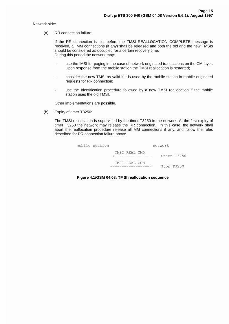
mobile station network
TMSI REAL CMD <---------------- Start T3250
TMSI REAL COM -----------------> Stop T3250
Figure 4.1/GSM 04.08: TMSI reallocation sequence
Page 16Draft prETS 300 940 (GSM 04.08 Version 5.6.1): August 1997
4.3.2 Authentication procedure
The purpose of the authentication procedure is twofold:
First to permit the network to check whether the identity provided by the mobile station isacceptable or not (see GSM 03.20);
Second to provide parameters enabling the mobile station to calculate a new ciphering key.
The cases where the authentication procedure should be used are defined in GSM 02.09.
The authentication procedure is always initiated and controlled by the network.
4.3.2.1 Authentication request by the network
The network initiates the authentication procedure by transferring an AUTHENTICATION REQUESTmessage across the radio interface and starts the timer T3260. The AUTHENTICATION REQUESTmessage contains the parameters necessary to calculate the response parameters (see GSM 03.20). Italso contains the ciphering key sequence number allocated to the key which may be computed from thegiven parameters.
4.3.2.2 Authentication response by the mobile station
The mobile station shall be ready to respond upon an AUTHENTICATION REQUEST message at anytime whilst a RR connection exists. It shall process the challenge information and send back anAUTHENTICATION RESPONSE message to the network. The new ciphering key calculated from thechallenge information shall overwrite the previous one and be stored on the SIM before theAUTHENTICATION RESPONSE message is transmitted. The ciphering key stored in the SIM shall beloaded in to the ME when any valid CIPHERING MODE COMMAND is received during an RR connection(the definition of a valid CIPHERING MODE COMMAND message is given in section 3.4.7.2). Theciphering key sequence number shall be stored together with the calculated key.
4.3.2.3 Authentication processing in the network
Upon receipt of the AUTHENTICATION RESPONSE message, the network stops the timer T3260 andchecks the validity of the response (see GSM 03.20).
4.3.2.4 Ciphering key sequence number
The security parameters for authentication and ciphering are tied together in sets, i.e. from a challengeparameter RAND both the authentication response SRES and the ciphering key can be computed giventhe secret key associated to the IMSI.
In order to allow start of ciphering on a RR connection without authentication, the ciphering key sequencenumbers are introduced. The sequence number is managed by the network in the way that theAUTHENTICATION REQUEST message contains the sequence number allocated to the key which maybe computed from the RAND parameter carried in that message.
The mobile station stores this number with the key, and indicates to the network in the first message(LOCATION UPDATING REQUEST, CM SERVICE REQUEST, PAGING RESPONSE, CMREESTABLISHMENT REQUEST) which sequence number the stored key has. When the deletion of thesequence number is described this also means that the associated key shall be considered as invalid.
The network may choose to start ciphering with the stored key (under the restrictions given in GSM 02.09)if the stored sequence number and the one given from the mobile station are equal.
Page 17Draft prETS 300 940 (GSM 04.08 Version 5.6.1): August 1997
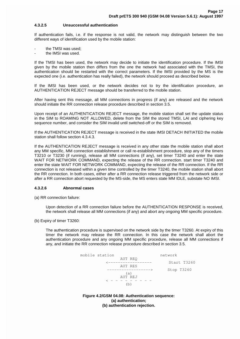
4.3.2.5 Unsuccessful authentication
If authentication fails, i.e. if the response is not valid, the network may distinguish between the twodifferent ways of identification used by the mobile station:
- the TMSI was used;- the IMSI was used.
If the TMSI has been used, the network may decide to initiate the identification procedure. If the IMSIgiven by the mobile station then differs from the one the network had associated with the TMSI, theauthentication should be restarted with the correct parameters. If the IMSI provided by the MS is theexpected one (i.e. authentication has really failed), the network should proceed as described below.
If the IMSI has been used, or the network decides not to try the identification procedure, anAUTHENTICATION REJECT message should be transferred to the mobile station.
After having sent this message, all MM connections in progress (if any) are released and the networkshould initiate the RR connection release procedure described in section 3.5.
Upon receipt of an AUTHENTICATION REJECT message, the mobile station shall set the update statusin the SIM to ROAMING NOT ALLOWED, delete from the SIM the stored TMSI, LAI and ciphering keysequence number, and consider the SIM invalid until switched-off or the SIM is removed.
If the AUTHENTICATION REJECT message is received in the state IMSI DETACH INITIATED the mobilestation shall follow section 4.3.4.3.
If the AUTHENTICATION REJECT message is received in any other state the mobile station shall abortany MM specific, MM connection establishment or call re-establishment procedure, stop any of the timersT3210 or T3230 (if running), release all MM connections (if any), set timer T3240 and enter the stateWAIT FOR NETWORK COMMAND, expecting the release of the RR connection. start timer T3240 andenter the state WAIT FOR NETWORK COMMAND, expecting the release of the RR connection. If the RRconnection is not released within a given time controlled by the timer T3240, the mobile station shall abortthe RR connection. In both cases, either after a RR connection release triggered from the network side orafter a RR connection abort requested by the MS-side, the MS enters state MM IDLE, substate NO IMSI.
4.3.2.6 Abnormal cases
(a) RR connection failure:
Upon detection of a RR connection failure before the AUTHENTICATION RESPONSE is received,the network shall release all MM connections (if any) and abort any ongoing MM specific procedure.
(b) Expiry of timer T3260:
The authentication procedure is supervised on the network side by the timer T3260. At expiry of thistimer the network may release the RR connection. In this case the network shall abort theauthentication procedure and any ongoing MM specific procedure, release all MM connections ifany, and initiate the RR connection release procedure described in section 3.5.
mobile station networkAUT REQ
<------------------ Start T3260AUT RES
------------------> Stop T3260(a)
AUT REJ< - - - - - - - - -
(b)
Figure 4.2/GSM 04.08: Authentication sequence:(a) authentication;
(b) authentication rejection.
Page 18Draft prETS 300 940 (GSM 04.08 Version 5.6.1): August 1997
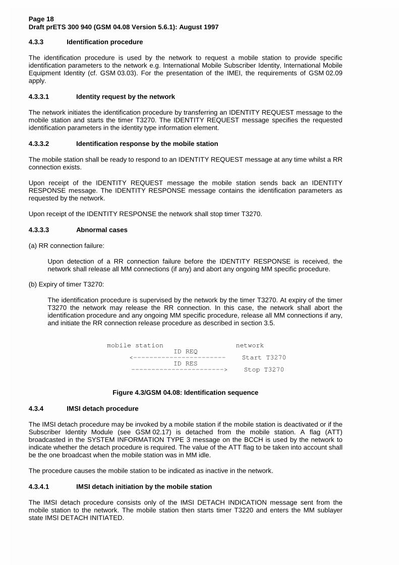
4.3.3 Identification procedure
The identification procedure is used by the network to request a mobile station to provide specificidentification parameters to the network e.g. International Mobile Subscriber Identity, International MobileEquipment Identity (cf. GSM 03.03). For the presentation of the IMEI, the requirements of GSM 02.09apply.
4.3.3.1 Identity request by the network
The network initiates the identification procedure by transferring an IDENTITY REQUEST message to themobile station and starts the timer T3270. The IDENTITY REQUEST message specifies the requestedidentification parameters in the identity type information element.
4.3.3.2 Identification response by the mobile station
The mobile station shall be ready to respond to an IDENTITY REQUEST message at any time whilst a RRconnection exists.
Upon receipt of the IDENTITY REQUEST message the mobile station sends back an IDENTITYRESPONSE message. The IDENTITY RESPONSE message contains the identification parameters asrequested by the network.
Upon receipt of the IDENTITY RESPONSE the network shall stop timer T3270.
4.3.3.3 Abnormal cases
(a) RR connection failure:
Upon detection of a RR connection failure before the IDENTITY RESPONSE is received, thenetwork shall release all MM connections (if any) and abort any ongoing MM specific procedure.
(b) Expiry of timer T3270:
The identification procedure is supervised by the network by the timer T3270. At expiry of the timerT3270 the network may release the RR connection. In this case, the network shall abort theidentification procedure and any ongoing MM specific procedure, release all MM connections if any,and initiate the RR connection release procedure as described in section 3.5.
mobile station networkID REQ
<----------------------- Start T3270ID RES
-----------------------> Stop T3270
Figure 4.3/GSM 04.08: Identification sequence
4.3.4 IMSI detach procedure
The IMSI detach procedure may be invoked by a mobile station if the mobile station is deactivated or if theSubscriber Identity Module (see GSM 02.17) is detached from the mobile station. A flag (ATT)broadcasted in the SYSTEM INFORMATION TYPE 3 message on the BCCH is used by the network toindicate whether the detach procedure is required. The value of the ATT flag to be taken into account shallbe the one broadcast when the mobile station was in MM idle.
The procedure causes the mobile station to be indicated as inactive in the network.
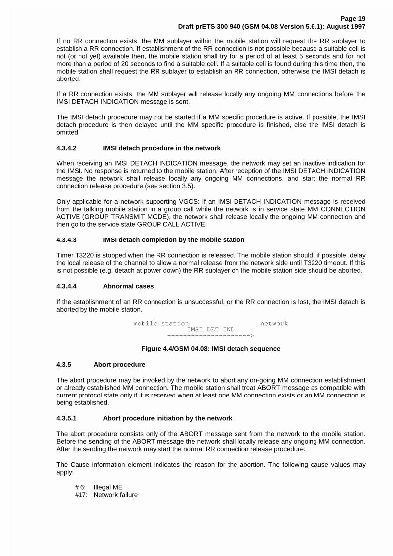
4.3.4.1 IMSI detach initiation by the mobile station
The IMSI detach procedure consists only of the IMSI DETACH INDICATION message sent from themobile station to the network. The mobile station then starts timer T3220 and enters the MM sublayerstate IMSI DETACH INITIATED.
Page 19Draft prETS 300 940 (GSM 04.08 Version 5.6.1): August 1997
If no RR connection exists, the MM sublayer within the mobile station will request the RR sublayer toestablish a RR connection. If establishment of the RR connection is not possible because a suitable cell isnot (or not yet) available then, the mobile station shall try for a period of at least 5 seconds and for notmore than a period of 20 seconds to find a suitable cell. If a suitable cell is found during this time then, themobile station shall request the RR sublayer to establish an RR connection, otherwise the IMSI detach isaborted.
If a RR connection exists, the MM sublayer will release locally any ongoing MM connections before theIMSI DETACH INDICATION message is sent.
The IMSI detach procedure may not be started if a MM specific procedure is active. If possible, the IMSIdetach procedure is then delayed until the MM specific procedure is finished, else the IMSI detach isomitted.
4.3.4.2 IMSI detach procedure in the network
When receiving an IMSI DETACH INDICATION message, the network may set an inactive indication forthe IMSI. No response is returned to the mobile station. After reception of the IMSI DETACH INDICATIONmessage the network shall release locally any ongoing MM connections, and start the normal RRconnection release procedure (see section 3.5).
Only applicable for a network supporting VGCS: If an IMSI DETACH INDICATION message is receivedfrom the talking mobile station in a group call while the network is in service state MM CONNECTIONACTIVE (GROUP TRANSMIT MODE), the network shall release locally the ongoing MM connection andthen go to the service state GROUP CALL ACTIVE.
4.3.4.3 IMSI detach completion by the mobile station
Timer T3220 is stopped when the RR connection is released. The mobile station should, if possible, delaythe local release of the channel to allow a normal release from the network side until T3220 timeout. If thisis not possible (e.g. detach at power down) the RR sublayer on the mobile station side should be aborted.
4.3.4.4 Abnormal cases
If the establishment of an RR connection is unsuccessful, or the RR connection is lost, the IMSI detach isaborted by the mobile station.
mobile station networkIMSI DET IND
--------------------->
Figure 4.4/GSM 04.08: IMSI detach sequence
4.3.5 Abort procedure
The abort procedure may be invoked by the network to abort any on-going MM connection establishmentor already established MM connection. The mobile station shall treat ABORT message as compatible withcurrent protocol state only if it is received when at least one MM connection exists or an MM connection isbeing established.
4.3.5.1 Abort procedure initiation by the network
The abort procedure consists only of the ABORT message sent from the network to the mobile station.Before the sending of the ABORT message the network shall locally release any ongoing MM connection.After the sending the network may start the normal RR connection release procedure.
The Cause information element indicates the reason for the abortion. The following cause values mayapply:
# 6: Illegal ME#17: Network failure
Page 20Draft prETS 300 940 (GSM 04.08 Version 5.6.1): August 1997
4.3.5.2 Abort procedure in the mobile station
At the receipt of the ABORT message the mobile station shall abort any MM connection establishment orcall re-establishment procedure and release all MM connections (if any). If cause value #6 is received themobile station shall delete any TMSI, LAI and ciphering key sequence number stored in the SIM, set theupdate status to ROAMING NOT ALLOWED (and store it in the SIM according to section 4.1.2.2) andconsider the SIM invalid until switch off or the SIM is removed. As a consequence the mobile stationenters state MM IDLE, substate NO IMSI after the release of the RR connection.
The mobile station shall then wait for the network to release the RR connection - see section 4.5.3.1.
4.3.6 MM information procedure
The MM information message support is optional in the network.
The MM information procedure may be invoked by the network at any time during an RR connection.
4.3.6.1 MM information procedure initiation by the network
The MM information procedure consists only of the MM INFORMATION message sent from the networkto the mobile station. During an RR connection, the network shall send none, one, or more MMINFORMATION messages to the mobile station. If more than one MM INFORMATION message is sent,the messages need not have the same content.
NOTE: The network may be able to select particular instants where it can send the MMINFORMATION message without adding delay to, or interrupting, any CM layertransaction, e.g. immediately after the AUTHENTICATION REQUEST message.
4.3.6.2 MM information procedure in the mobile station
When the mobile station (supporting the MM information message) receives an MM INFORMATIONmessage, it shall accept the message and optionally use the contents to update appropriate informationstored within the mobile station.
If the mobile station does not support the MM information message the mobile station shall ignore thecontents of the message and return an MM STATUS message with cause #97.
Page 21Draft prETS 300 940 (GSM 04.08 Version 5.6.1): August 1997
4.4 MM specific procedures
A MM specific procedure can only be started if no other MM specific procedure is running or no MMconnection exists between the network and the mobile station. The end of the running MM specificprocedure or the release of all MM connections have to be awaited before a new MM specific procedurecan be started.
During the lifetime of a MM specific procedure, if a MM connection establishment is requested by a CMentity, this request will either be rejected or be delayed until the running MM specific procedure isterminated (this depends on the implementation).
Any MM common procedure (except IMSI detach) may be initiated during a MM specific procedure.
Unless it has specific permission from the network (follow-on proceed) the mobile station side shouldawait the release of the RR connection used for a MM specific procedure before a new MM specificprocedure or MM connection establishment is started.
NOTE: The network side may use the same RR connection for MM connection management.
4.4.1 Location updating procedure
The location updating procedure is a general procedure which is used for the following purposes:
- normal location updating (described in this section);- periodic updating (see section 4.4.2);- IMSI attach (see section 4.4.3).
The normal location updating procedure is used to update the registration of the actual Location Area of amobile station in the network. The location updating type information element in the LOCATIONUPDATING REQUEST message shall indicate normal location updating. The conditions under which thenormal location updating procedure is used by a mobile station in the MM IDLE state are defined for eachservice state in section 4.2.2.
Only applicable for mobile stations supporting VGCS listening or VBS listening: A mobile station in RRgroup receive mode is in the MM IDLE state, substate RECEIVING GROUP CALL (NORMAL SERVICE)or RECEIVING GROUP CALL (LIMITED SERVICE). To perform a location updating, the MS in RR groupreceive mode shall leave the group receive mode, establish an independent dedicated RR connection toperform the location updating as described above and return to the RR group receive mode afterwards.
The normal location updating procedure shall also be started if the network indicates that the mobilestation is unknown in the VLR as a response to MM connection establishment request.
To limit the number of location updating attempts made, where location updating is unsuccessful, anattempt counter is used. The attempt counter is reset when a mobile station is switched on or a SIM cardis inserted.
Upon successful location updating the mobile station sets the update status to UPDATED in the SIM, andstores the received Location Area Identification in the SIM. The attempt counter shall be reset.
The detailed handling of the attempt counter is described in 4.4.4.6 to 4.4.4.9.
The Mobile Equipment shall contain a list of "forbidden location areas for roaming", as well as a list of"forbidden location areas for regional provision of service". These lists shall be erased when the MS isswitched off or when the SIM is removed, and periodically (with period in the range 12 to 24 hours). Thelocation area identification received on the BCCH that triggered the location updating request shall beadded to the suitable list whenever a location update reject message is received with the cause "Roamingnot allowed in this location area" or with the cause "Location Area not allowed". The lists shallaccommodate each 10 or more location area identifications. When the list is full and a new entry has to beinserted, the oldest entry shall be deleted.
The cell selection processes in the different states are described in GSM 03.22 and GSM 05.08.
Page 22Draft prETS 300 940 (GSM 04.08 Version 5.6.1): August 1997
The location updating procedure is always initiated by the mobile station.
4.4.2 Periodic updating
Periodic updating may be used to notify periodically the availability of the mobile station to the network.Periodic updating is performed by using the location updating procedure. The location updating typeinformation element in the LOCATION UPDATING REQUEST message shall indicate periodic updating.
The procedure is controlled by the timer T3212 in the mobile station. If the timer is not already started, thetimer is started each time the mobile station enters the MM IDLE substate NORMAL SERVICE orATTEMPTing TO UPDATE. When the MS leaves the MM Idle State the timer T3212 shall continuerunning until explicitly stopped.
The timer is stopped (shall be set to its initial value for the next start) when:
- a LOCATION UPDATING ACCEPT or LOCATION UPDATING REJECT message is received;- an AUTHENTICATION REJECT message is received;- the first MM message is received, or ciphering mode setting is completed in the case of MM
connection establishment, except when the most recent service state is LIMITED SERVICE;- the mobile station has responded to paging and thereafter has received the first correct layer 3
message except RR message;- the mobile station is deactivated (i.e. equipment powered down or SIM removed).
When the timer T3212 expires, the location updating procedure is started and the timer shall be set to itsinitial value for the next start. If the mobile station is in other state than MM Idle when the timer expires thelocation updating procedure is delayed until the MM Idle State is entered.
The conditions under which the periodic location updating procedure is used by a mobile station in the MMIDLE state are defined for each service state in section 4.2.2.
If the mobile station is in service state NO CELL AVAILABLE, LIMITED SERVICE, PLMN SEARCH orPLMN SEARCH-NORMAL SERVICE when the timer expires the location updating procedure is delayeduntil this service state is left. The (periodic) location updating procedure is not started if the BCCHinformation at the time the procedure is triggered indicates that periodic location shall not be used. Thetimeout value is broadcasted in the SYSTEM INFORMATION TYPE 3 message on the BCCH, in theControl channel description IE, see section 10.5.2.11.
The T3212 timeout value shall not be changed in the NO CELL AVAILABLE, LIMITED SERVICE, PLMNSEARCH and PLMN SEARCH-NORMAL SERVICE states.
When a change of the T3212 timeout value has to be taken into account and the timer is running (atchange of the serving cell or, change of the broadcast value of T3212), the MS shall behave as follows:
Let t1 be the new T3212 timeout value and let t be the current timer value at the moment of thechange to the new T3212 timeout value; then the timer shall be restarted with the value t modulo t1.
When the mobile station is activated, or when a change of the T3212 timeout value has to be taken intoaccount and the timer is not running, the mobile station shall behave as follows:
Let t1 be the new T3212 timeout value, the new timer shall be started at a value randomly,uniformly drawn between 0 and t1.
4.4.3 IMSI attach procedure
The IMSI attach procedure is the complement of the IMSI detach procedure (see section 4.3.4). It is usedto indicate the IMSI as active in the network. A flag (ATT) is broadcast in the SYSTEM INFORMATIONTYPE 3 message. It indicates whether the attach and detach procedures are required to be used or not.
Page 23Draft prETS 300 940 (GSM 04.08 Version 5.6.1): August 1997
The IMSI attach procedure is invoked if the detach/attach procedures are required by the network and anIMSI is activated in a mobile station (i.e. activation of a mobile station with plug-in SIM, insertion of a cardin a card-operated mobile station etc.) within coverage area from the network or a mobile station with anIMSI activated outside the coverage area enters the coverage area. The IMSI attach procedure is usedonly if the update status is UPDATED and if the stored Location Area Identification is the same as the onewhich is actually broadcasted on the BCCH of the current serving cell. Otherwise a normal locationupdating procedure (see section 4.4.1) is invoked independently of the ATT flag indication.
IMSI attach is performed by using the location updating procedure. The location updating type informationelement in the LOCATION UPDATING REQUEST message shall in this case indicate IMSI attach.
4.4.4 Generic Location Updating procedure
4.4.4.1 Location updating initiation by the mobile station
Any timer used for triggering the location updating procedure (e.g. T3211, T3212) is stopped if running.
As no RR connection exists at the time when the location updating procedure has to be started, the MMsublayer within the mobile station will request the RR sublayer to establish a RR connection and enterstate WAIT FOR RR CONNECTION (LOCATION UPDATE). The procedure for establishing an RRconnection is described in section 3.3.
The mobile station initiates the location updating procedure by sending a LOCATION UPDATINGREQUEST message to the network, starts the timer T3210 and enters state LOCATION UPDATINGINITIATED. The location updating type information element shall indicate what kind of updating isrequested.
4.4.4.1a Network Request for Additional mobile station Capability Information
The network may initiate the classmark interrogation procedure, for example, to obtain further informationon the mobile station's encryption capabilities.
4.4.4.2 Identification request from the network
The network may initiate the identification procedure, e.g. if the network is unable to get the IMSI based onthe TMSI and LAI used as identification by the mobile station (see section 4.3.3).
4.4.4.3 Authentication by the network
The authentication procedure (see section 4.3.2) may be initiated by the network upon receipt of theLOCATION UPDATING REQUEST message from the mobile station. (See the cases defined inGSM 02.09).
4.4.4.4 Ciphering mode setting by the network
The ciphering mode setting procedure (see section 3.4.7) may be initiated by the network, e.g., if a newTMSI has to be allocated.
4.4.4.5 Attempt Counter
To limit the number of location updating attempts made, where location updating is unsuccessful, anattempt counter is used. It counts the number of consecutive unsuccessful location update attempts.
The attempt counter is incremented when a location update procedure fails. The specific situations isspecified in section 4.4.4.9.
The attempt counter is reset when:
- the mobile station is powered on;- a SIM is inserted;- location update is successfully completed;- location update completed with cause #11, #12 or #13 (see section 4.4.4.7).
Page 24Draft prETS 300 940 (GSM 04.08 Version 5.6.1): August 1997
and in case of service state ATTEMPTING to UPDATE:
- a new location area is entered;- expiry of timer T3212;- location update is triggered by CM sublayer requests.
The attempt counter is used when deciding whether to re-attempt a location update after timeout of timerT3211.
4.4.4.6 Location updating accepted by the network
If the location updating is accepted by the network a LOCATION UPDATING ACCEPT message istransferred to the mobile station.
In case the identity confidentiality service is active (see section 4.3.1 and 4.4.4.4), the TMSI reallocationmay be part of the location updating procedure. The TMSI allocated is then contained in the LOCATIONUPDATING ACCEPT message together with the location area identifier LAI. The network shall in thiscase start the supervision timer T3250 as described in section 4.3.1.
If the network wishes to prolong the RR connection to allow the mobile station to initiate MM connectionestablishment (for example if the mobile station has indicated in the LOCATION UPDATING REQUESTthat it has a follow-on request pending) the network shall send "follow on proceed" in the LOCATIONUPDATING ACCEPT and start timer T3255.
The mobile station receiving a LOCATION UPDATING ACCEPT message shall store the receivedlocation area identification LAI, stop timer T3210, reset the attempt counter and set the update status inthe SIM to UPDATED. If the message contains an IMSI, the mobile station is not allocated any TMSI, andshall delete any TMSI in the SIM accordingly. If the message contains a TMSI, the mobile station isallocated this TMSI, and shall store this TMSI in the SIM and a TMSI REALLOCATION COMPLETE shallbe returned to the network. If neither IMSI nor TMSI is received in the LOCATION UPDATING ACCEPTmessage, the old TMSI if any available shall be kept.
If the LAI or PLMN identity contained in the LOCATION UPDATING ACCEPT message is a member ofany of the "forbidden lists" then any such entries shall be deleted.
After that, the mobile station shall act according to the presence of the "Follow-on proceed" informationelement in the LOCATION UPDATING ACCEPT; if this element is present and the mobile station has aCM application request pending, it shall send a CM SERVICE REQUEST to the network and proceed asin section 4.5.1.1. Otherwise, it shall start timer T3240 and enter state WAIT FOR NETWORKCOMMAND.
4.4.4.7 Location updating not accepted by the network
If the location updating cannot be accepted the network sends a LOCATION UPDATING REJECTmessage to the mobile station. The mobile station receiving a LOCATION UPDATING REJECT messageshall stop the timer T3210, store the reject cause, start T3240, enter state LOCATION UPDATINGREJECTED await the release of the RR connection triggered by the network. Upon the release of the RRconnection the mobile station shall take the following actions depending on the stored reject cause:
# 2: IMSI unknown in HLR;# 3: Illegal MS; or# 6: Illegal ME.
The mobile station shall set the update status to ROAMING NOT ALLOWED (and store it in theSIM according to section 4.1.2.2), and delete any TMSI, stored LAI and ciphering key sequencenumber and shall consider the SIM as invalid until switch-off or the SIM is removed.
Page 25Draft prETS 300 940 (GSM 04.08 Version 5.6.1): August 1997
# 11: PLMN not allowed;# 12: Location Area not allowed; or# 13: Roaming not allowed in this location area.
The mobile station shall delete any LAI, TMSI and ciphering key sequence number stored in theSIM, reset the attempt counter, set the update status to ROAMING NOT ALLOWED (and store it inthe SIM according to section 4.1.2.2). The mobile station shall store the LAI or the PLMN identity inthe suitable forbidden list, i.e. in the "forbidden PLMN list" for cause #11, in the list of "forbiddenlocation areas for regional provision of service" for cause #12, and in the list of "forbidden locationareas for roaming" for cause #13. In addition, the MS will memorize if cause #13 was received, soto perform a PLMN selection instead of a cell selection when back to the MM IDLE state.
Other values are considered as abnormal cases and the specification of the mobile station behaviour inthose cases is given in section 4.4.4.9.
4.4.4.8 Release of RR connection after location updating
When the Location updating procedure is finished (see sections 4.4.4.6 and 4.4.4.7) the mobile stationshall (except in the case where the mobile has a follow-on CM application request pending and hasreceived the follow-on proceed indication, see 4.4.4.6) set timer T3240 and enter the state WAIT FORNETWORK COMMAND, expecting the release of the RR connection. The network may decide to keepthe RR connection for network initiated establishment of a MM connection, or to allow for mobile initiatedMM connection establishment.
Any release of the RR connection shall be initiated by the network according to section 3.5. If the RRconnection is not released within a given time controlled by the timer T3240, the mobile station shall abortthe RR connection. In both cases, either after a RR connection release triggered from the network side orafter a RR connection abort requested by the MS-side, the MS shall return to state MM IDLE.
At transition to state MM IDLE, substates NORMAL SERVICE or RECEIVING GROUP CALL (NORMALSERVICE) or ATTEMPTING TO UPDATE either timer T3212 or timer T3211 is started as described insection 4.4.4.9.
4.4.4.9 Abnormal cases on the mobile station side
The different abnormal cases that can be identified are the following:
a) Access barred because of access class controlThe location updating procedure is not started. The mobile station stays in the current serving celland applies normal cell reselection process. The procedure is started as soon as possible and if stillnecessary (when the barred state is ended or because of a cell change)
b) The answer to random access is an IMMEDIATE ASSIGNMENT REJECT messageThe location updating is not started. The mobile station stays in the chosen cell and applies normalcell selection process. The waiting timer T3122 is reset when a cell change occurs. The procedureis started as soon as possible after T3122 timeout if still necessary.
c) Random access failureTimer T3213 is started. When it expires the procedure is attempted again if still necessary.
NOTE: As specified in GSM 05.08, a cell reselection then takes place, with return to the cellinhibited for 5 seconds if there is at least one other suitable cell. Typically the selectionprocess will take the mobile station back to the cell where the random access failedafter 5 seconds.
If at the expiry of timer T3213 a new cell has not been selected due to the lack of valid information(see GSM 05.08), the mobile station may as an option delay the repeated attempt for up to 8seconds to allow cell re-selection to take place. In this case the procedure is attempted as soon asa new cell has been selected or the mobile station has concluded that no other cell can beselected.
If random access failure occurs for two successive random access attempts for location updatingthe mobile station proceeds as specified below.
Page 26Draft prETS 300 940 (GSM 04.08 Version 5.6.1): August 1997
d) RR connection failureThe procedure is aborted and the mobile station proceeds as specified below.
e) T3210 timeoutThe procedure is aborted, the RR connection is aborted and the MS proceeds as specified below.
f) RR release before the normal end of procedureThe procedure is aborted and the mobile station proceeds as specified below.
g) Location updating reject, other causes than those treated in section 4.4.4.7The MS waits for release of the RR connection as specified in section 4.4.4.8, and then proceedsas specified below.
In cases d) to g) above and for repeated failures as defined in c) above the mobile station proceeds asfollows. Timer T3210 is stopped if still running. The RR Connection is aborted in case of timer T3210timeout. The attempt counter is incremented. The next actions depend on the Location Area Identities(stored and received from the BCCH of the current serving cell) and the value of the attempt counter.
– the update status is UPDATED, and the stored LAI is equal to the one received on the BCCH fromthe current serving cell and the attempt counter is smaller than 4:
The mobile station shall keep the update status to UPDATED, the MM IDLE sub-state after the RRconnection release is NORMAL SERVICE. The mobile station shall memorize the location updatingtype used in the location updating procedure. It shall start timer T3211 when the RR connection isreleased. When timer T3211 expires the location updating procedure is triggered again with thememorized location updating type;
– either the update status is different from UPDATED, or the stored LAI is different from the onereceived on the BCCH from the current serving cell, or the attempt counter is greater or equal to 4:
The mobile station shall delete any LAI, TMSI, ciphering key sequence number stored in the SIM,set the update status to NOT UPDATED and enter the MM IDLE sub-state ATTEMPTING TOUPDATE when the RR connection is released (See section 4.2.2.2 for the subsequent actions). Ifthe attempt counter is smaller than 4, the mobile station shall memorize that timer T3211 is to bestarted when the RR connection is released, otherwise it shall memorize that timer T3212 is to bestarted when the RR connection is released.
4.4.4.10 Abnormal cases on the network side
a) RR connection failure
If a RR connection failure occurs during a common procedure integrated with the location updatingprocedure, the behaviour of the network should be according to the description of that commonprocedure.
If a RR connection failure occurs when a common procedure does not exist, the location updatingprocedure towards the mobile station should be aborted.
b) protocol error
If the LOCATION UPDATING REQUEST message is received with a protocol error, the networkshould, if possible, return a LOCATION UPDATING REJECT message with one of the followingReject causes:
#96: Mandatory information element error#99: Information element non-existent or not implemented#100: Conditional IE error#111: Protocol error, unspecified
Page 27Draft prETS 300 940 (GSM 04.08 Version 5.6.1): August 1997
Having sent the response, the network should start the channel release procedure (seesection 3.5).
mobile station network LOC UPD REQ
Start T3210 -----------------------> LOC UPD ACC
Stop T3210 <---------------------- LOC UPD REJ
" <- - - - - - - - - - - -
Figure 4.5/GSM 04.08: Location updating sequence
4.5 Connection management sublayer service provision
The concept of MM connection is introduced in this section. This concept is mainly a descriptive tool: Theestablishment of an MM connection by the network can be local (ie. it is achieved by the transmission ofthe first CM layer message and without the transmission of any MM layer messages) or can be achievedby the transmission of a CM SERVICE PROMPT message (eg. in the case of certain ring back services).The and the release of an MM connection by the network or by the mobile station is always local, i.e.these purposes can be achieved without sending any MM messages over the radio interface. (On thecontrary, establishment of an MM connection by the mobile station requires the sending of MM messagesover the radio interface. An exception is VGCS, where an MM connection will be established as result ofan uplink access procedure (see section 3.7.2.1.1).)
The Mobility Management (MM) sublayer is providing connection management services to the differententities of the upper Connection management (CM) sublayer (see GSM 04.07). It offers to a CM entity thepossibility to use an MM connection for the exchange of information with its peer entity. An MM connectionis established and released on request from a CM entity. Different CM entities communicate with theirpeer entity using different MM connections. Several MM connections may be active at the same time.
An MM connection requires an RR connection. All simultaneous MM connections for a given mobilestation use the same RR connection.
In the following sections, the procedures for establishing, re-establishing, maintaining, and releasing anMM connection are described, usually separately for the mobile station and the network side.
4.5.1 MM connection establishment
4.5.1.1 MM connection establishment initiated by the mobile station
Upon request of a CM entity to establish an MM connection the MM sublayer first decides whether toaccept, delay, or reject this request:
- An MM connection establishment may only be initiated by the mobile station when the followingconditions are fulfilled:
- Its update status is UPDATED.- The MM sublayer is in one of the states MM IDLE or MM connection active but not in MM
connection active (Group call).
An exception from this general rule exists for emergency calls (see section 4.5.1.5). A furtherexception is defined in the following clause.
- If an MM specific procedure is running at the time the request from the CM sublayer is received,and the LOCATION UPDATING REQUEST message has been sent, the request will either berejected or delayed, depending on implementation, until the MM specific procedure is finished and,provided that the network has not sent a "follow-on proceed" indication, the RR connection isreleased. If the LOCATION UPDATING REQUEST message has not been sent, the mobile stationmay include a "follow-on request" indicator in the message. The mobile station shall then delay therequest until the MM specific procedure is completed, when it may be given the opportunity by thenetwork to use the RR connection: see section 4.4.4.6.
Page 28Draft prETS 300 940 (GSM 04.08 Version 5.6.1): August 1997
In order to establish an MM connection, the mobile station proceeds as follows:
a) If no RR connection exists, the MM sublayer requests the RR sublayer to establish an RRconnection and enters MM sublayer state WAIT FOR RR CONNECTION (MM CONNECTION).This request contains an establishment cause and a CM SERVICE REQUEST or NOTIFICATIONRESPONSE message. When the establishment of an RR connection is indicated by the RRsublayer (this indication implies that the CM SERVICE REQUEST or NOTIFICATION RESPONSEmessage has been successfully transferred via the radio interface, see section 2.2), the MMsublayer of the mobile station starts timer T3230, gives an indication to the CM entity that requestedthe MM connection establishment, and enters MM sublayer state WAIT FOR OUTGOING MMCONNECTION.
b) If an RR connection is available, the MM sublayer of the mobile station sends a CM SERVICEREQUEST or NOTIFICATION RESPONSE message to the network, starts timer T3230, gives anindication to the CM entity that requested the MM connection establishment, and enters:
- MM sublayer state WAIT FOR OUTGOING MM CONNECTION, if no MM connection isactive;
- MM sublayer state WAIT FOR ADDITIONAL OUTGOING MM CONNECTION, if at least oneMM connection is active;
- If an RR connection exists but the mobile station is in the state WAIT FOR NETWORKCOMMAND then any requests from the CM layer that are received will either be rejected ordelayed until this state is left.
c) Only applicable for mobile stations supporting VGCS talking:
If a mobile station which is in the MM sublayer state MM IDLE, service state RECEIVING GROUPCALL (NORMAL SERVICE), receives a request from the GCC sublayer to perform an uplinkaccess, the MM sublayer requests the RR sublayer to perform an uplink access procedure andenters MM sublayer state WAIT FOR RR CONNECTION (GROUP TRANSMIT MODE).
When a successful uplink access is indicated by the RR sublayer, the MM sublayer of the mobilestation gives an indication to the GCC sublayer and enters MM sublayer state MM CONNECTIONACTIVE (GROUP TRANSMIT MODE).
When an uplink access reject is indicated by the RR sublayer, the MM sublayer of the mobilestation gives an indication to the GCC sublayer and enters the MM sublayer state MM IDLE, servicestate RECEIVING GROUP CALL (NORMAL SERVICE).
In the network, if an uplink access procedure is performed, the RR sublayer in the network providesan indication to the MM sublayer together with the mobile subscriber identity received in theTALKER INDICATION message. The network shall then enter the MM sublayer state MMCONNECTION ACTIVE (GROUP TRANSMIT MODE).
The CM SERVICE REQUEST message contains the
- mobile identity according to section 10.5.1.4;- mobile station classmark 2;- ciphering key sequence number; and- CM service type identifying the requested type of transaction (e.g. mobile originating call
establishment, emergency call establishment, short message service, supplementary serviceactivation).
A MS supporting eMLPP may optionally include a priority level in the CM SERVICE REQUEST message.
Only applicable for mobile stations supporting VGCS listening or VBS listening:
The NOTIFICATION RESPONSE message is used if a mobile station has received a notificationmessage on the NCH for a VGCS or VBS call without a description of the respective VGCS or VBSchannel. The mobile station therefore establishes an MM connection with a NOTIFICATION RESPONSEin order to obtain the necessary details from the network. The NOTIFICATION RESPONSE messagecontains the
Page 29Draft prETS 300 940 (GSM 04.08 Version 5.6.1): August 1997
- mobile identity according to section 10.5.1.4;- mobile station classmark 2; and- notified voice group or broadcast call reference according to section 10.5.1.9.
A collision may occur when a CM layer message is received by the mobile station in MM sublayer stateWAIT FOR OUTGOING MM CONNECTION or in WAIT FOR ADDITIONAL OUTGOING MMCONNECTION. In this case the MM sublayer in the MS shall establish a new MM connection for theincoming CM message as specified in 4.5.1.3.
Upon receiving a CM SERVICE REQUEST or NOTIFICATION RESPONSE message, the network shallanalyse its content. The type of semantic analysis may depend on other on going MM connection(s).Depending on the type of request and the current status of the RR connection, the network may start anyof the MM common procedures and RR procedures.
The network may initiate the classmark interrogation procedure, for example, to obtain further informationon the mobile station's encryption capabilities.
The identification procedure (see section 4.3.3) may be invoked for instance if a TMSI provided by themobile station is not recognized.
The network may invoke the authentication procedure (see section 4.3.2) depending on the CM servicetype.
The network decides also if the ciphering mode setting procedure shall be invoked (see section 3.4.7).
NOTE: If the CM_SERVICE_REQUEST message contains a priority level the network mayuse this to perform queuing and pre-emption as defined in GSM 03.67.
An indication from the RR sublayer that the ciphering mode setting procedure is completed, or receptionof a CM SERVICE ACCEPT message, shall be treated as a service acceptance indication by the mobilestation. The MM connection establishment is completed, timer T3230 shall be stopped, the CM entity thatrequested the MM connection shall be informed, and MM sublayer state MM CONNECTION ACTIVE isentered. The MM connection is considered to be active.
If the service request cannot be accepted, the network returns a CM SERVICE REJECT message to themobile station.
The reject cause information element (see 10.5.3.6 and Annex G) indicates the reason for rejection. Thefollowing cause values may apply:
#4 : IMSI unknown in VLR #6 : Illegal ME#17 : Network failure#22 : Congestion#32 : Service option not supported#33 : Requested service option not subscribed#34 : Service option temporarily out of order
If no other MM connection is active, the network may start the RR connection release (see section 3.5)when the CM SERVICE REJECT message is sent.
If a CM SERVICE REJECT message is received by the mobile station, timer T3230 shall be stopped, therequesting CM sublayer entity informed. Then the mobile station shall proceed as follows:
- If the cause value is not #4 or #6 the MM sublayer returns to the previous state (the state where therequest was received). Other MM connections shall not be affected by the CM SERVICE REJECTmessage.
- If cause value #4 is received, the mobile station aborts any MM connection, deletes any TMSI, LAIand ciphering key sequence number in the SIM, changes the update status to NOT UPDATED (andstores it in the SIM according to section 4.1.2.2), and enters the MM sublayer state WAIT FORNETWORK COMMAND. If subsequently the RR connection is released or aborted, this will force
Page 30Draft prETS 300 940 (GSM 04.08 Version 5.6.1): August 1997
the mobile station to initiate a normal location updating). Whether the CM request shall bememorized during the location updating procedure, is a choice of implementation.
- If cause value #6 is received, the mobile station aborts any MM connection, deletes any TMSI, LAI
and ciphering key sequence number in the SIM, changes the update status to ROAMING NOTALLOWED (and stores it in the SIM according to section 4.1.2.2), and enters the MM sublayer stateWAIT FOR NETWORK COMMAND. The mobile station shall consider the SIM as invalid untilswitch-off or the SIM is removed.
4.5.1.2 Abnormal cases
Mobile station side:
a) RR connection failure or IMSI deactivation
If an RR connection failure occurs or the IMSI is deactivated during the establishment of an MMconnection, the MM connection establishment is aborted, timers T3230 is stopped, and anindication is given to the CM entity that requested the MM connection establishment. This shall betreated as a rejection for establishment of the new MM connection, and the MM sublayer shallrelease all active MM connections.
b) T3230 expiry
If T3230 expires (i.e. no response is given but a RR connection is available) the MM connectionestablishment is aborted and the requesting CM sublayer is informed. If no other MM connectionexists then the mobile station shall proceed as described in section 4.5.3.1 for release of the RRconnection. Otherwise the mobile station shall return to the MM sublayer state where the request ofan MM connection was received, i.e. to MM sublayer state MM connection active. Other ongoingMM connections (if any) shall not be affected.
c) Reject cause values #95, #96, #97, #99, #100, #111 received
The same actions as on timer expiry shall be taken by the mobile station.
d) Random access failure or RR connection establishment failure
If the mobile station detects a random access failure or RR connection establishment failure duringthe establishment of an MM connection, it aborts the MM connection establishment and gives anindication to the CM entity that requested the MM connection establishment.
NOTE: Further actions of the mobile station depend on the RR procedures and MM specificprocedures during which the abnormal situation has occurred and are describedtogether with those procedures.
Network side:
a) RR connection failure
The actions to be taken upon RR connection failure within a MM common procedure are describedtogether with that procedure. A RR connection failure occurring outside such MM commonprocedures, shall trigger the release of all active MM connections if any.
b) Invalid message or message content
Upon reception of an invalid initial message or a CM SERVICE REQUEST message with invalidcontent, a CM SERVICE REJECT message shall be returned with one of the following appropriateReject cause indications:# 95: Semantically incorrect message# 96: Mandatory information element error# 97: Message type non-existent or not implemented# 99: Information element non-existent or not implemented# 100:Conditional IE error# 111:Protocol error, unspecified
Page 31Draft prETS 300 940 (GSM 04.08 Version 5.6.1): August 1997
When the CM SERVICE REJECT message has been sent, the network may start RR connectionrelease if no other MM connections exist or if the abnormal condition also has influence on theother MM connections.
4.5.1.3 MM connection establishment initiated by the network
4.5.1.3.1 Mobile Terminating CM Activity
When a CM sublayer entity in the network requests the MM sublayer to establish a MM connection, theMM sublayer will request the establishment of an RR connection to the RR sublayer if no RR connectionto the desired mobile station exists. The MM sublayer is informed when the paging procedure is finished(see section 3.3.2). and the mobile station shall enter the MM state WAIT FOR NETWORK COMMAND.
(* editor’s note: this does not appear to be stated any where other than in fig 4.1a. Without this statement,there does not seem to be anything to stop the mobile sending a CM SERVICE REQUEST messagewhich might cross (ambiguously) with a CIPHERING MODE COMMAND message. *)
When an RR connection is established (or if it already exists at the time the request is received), the MMsublayer may initiate any of the MM common procedures (except IMSI detach); it may request the RRsublayer to perform the RR classmark interrogation procedure, and/or the ciphering mode settingprocedure.
When all MM and RR procedures are successfully completed which the network considers necessary, theMM sublayer will inform the requesting mobile terminating CM sublayer entity on the success of the MMconnection establishment.
If an RR connection already exists and no MM specific procedure is running, the network may alsoestablish a new mobile terminating MM connection by sending a CM message with a new PD/TIcombination.
If the establishment of an RR connection is unsuccessful, or if any of the MM common procedures or theciphering mode setting fail, this is indicated to the CM layer with an appropriate error cause.
If an RR connection used for a MM specific procedure exists to the mobile station, the CM request may berejected or delayed depending on implementation. When the MM specific procedure has been completed,the network may use the same RR connection for the delayed CM request.
Only applicable in case of VGCS talking:
In the MM CONNECTION ACTIVE (GROUP TRANSMIT MODE) the mobile station is in RR Grouptransmit mode. There shall be only one MM connection active.
When in MM CONNECTION ACTIVE (GROUP TRANSMIT MODE) state, the MM sublayer in the networkshall reject the request for the establishment of another MM connection by any CM layer.
If the RR sublayer in the network indicates a request to perform a transfer of the mobile station from RRconnected mode to RR Group transmit mode which will result in a transition from MM CONNECTIONACTIVE state to MM CONNECTION ACTIVE (GROUP TRANSMIT MODE) state in the MM sublayer, theMM sublayer shall not allow the transition if more than one MM connection is active with the mobilestation.,
4.5.1.3.2 Mobile Originating CM Activity
When a CM sublayer entity in the network requests the MM sublayer to establish a MM connection, theMM sublayer will request the establishment of an RR connection to the RR sublayer if no RR connectionto the desired mobile station exists. The MM sublayer is informed when the paging procedure is finished(see section 3.3.2) and the mobile station shall enter the MM state WAIT FOR NETWORK COMMAND.
When an RR connection is established (or if it already exists at the time the request is received), the MMsublayer may initiate any of the MM common procedures (except IMSI detach), it may request the RR
Page 32Draft prETS 300 940 (GSM 04.08 Version 5.6.1): August 1997
sublayer to perform the RR classmark interrogation procedure and/or the ciphering mode settingprocedure.
The network should use the information contained in the Mobile Station Classmark Type 2 IE on themobile station’s support for “Network Initiated MO CM Connection Request” to determine whether to:
not start this procedure (eg if an RR connection already exists), or, to continue this procedure, or, to release the newly established RR connection.
In the case of a “Network Initiated MO CM Connection Request” the network shall use the established RRconnection to send a CM SERVICE PROMPT message to the mobile station.
For a mobile station which supports “Network Initiated MO CM Connection Request”, the CM SERVICEPROMPT message identifies the CM entity in the mobile station which shall be informed of the completionof the MM connection. A mobile that does not support “Network Initiated MO CM Connection Request”shall return an MM STATUS message with cause #97 “message type non-existent or not implemented” tothe network.
If the mobile station supports “Network Initiated MO CM Connection Request” but the identified CM entityin the mobile station does not provide the associated support, then the mobile station shall send an MMSTATUS message with cause “Service option not supported”. In the case of a temporary CM problem (eglack of transaction identifiers) then the mobile station shall send an MM STATUS message with cause“Service option temporarily out of order”.
If an RR connection already exists and no MM specific procedure is running, the network may use it tosend the CM SERVICE PROMPT message.
If the establishment of an RR connection is unsuccessful, or if any of the MM common procedures or theciphering mode setting fail, this is indicated to the CM layer in the network with an appropriate error cause.
If an RR connection used for a MM specific procedure exists to the mobile station, the “Network InitiatedMO CM Connection Request” may be rejected or delayed depending on implementation. When the MMspecific procedure has been completed, the network may use the same RR connection for the delayed“Network Initiated MO CM Connection Request”.
4.5.1.4 Abnormal cases
The behaviour upon abnormal events is described together with the relevant RR procedure or MMcommon procedure.
4.5.1.5 MM connection establishment for emergency calls
A MM connection for an emergency call may be established in all states of the mobility managementsublayer which allow MM connection establishment for a normal originating call. In addition, establishmentmay be attempted in all service states where a cell is selected (see 4.2.2) but not in the MMCONNECTION ACTIVE state (GROUP TRANSMIT MODE) state. However, as a network dependentoption, a MM connection establishment for emergency call may be rejected in some of the states.
When a user requests an emergency call establishment the mobile station will send a CM SERVICEREQUEST message to the network with a CM service type information element indicating emergency callestablishment. If the network does not accept the emergency call request, e.g., because IMEI was usedas identification and this capability is not supported by the network, the network will reject the request byreturning a CM SERVICE REJECT message to the mobile station.
The reject cause information element indicates the reason for rejection. The following cause values mayapply:
#3 "Illegal MS"#4 "IMSI unknown in VLR"#5 "IMEI not accepted"#6 "Illegal ME"#17 "Network failure"
Page 33Draft prETS 300 940 (GSM 04.08 Version 5.6.1): August 1997
#22 "Congestion"#32 "Service option not supported"#34 "Service option temporarily out of order"
With the above defined exceptions, the procedures described for MM connection establishment in 4.5.1.1and 4.5.1.2 shall be followed.
NOTE: Normally, the mobile station will be identified by an IMSI or a TMSI. However, if noneof these identifiers is available in the mobile station, then the mobile station shall usethe IMEI for identification purposes. The network may in that case reject the request byreturning a CM SERVICE REJECT message with reject cause:
#5 "IMEI not accepted".
4.5.1.6 Call re-establishment
The re-establishment procedure allows a MS to resume a connection in progress after a radio link failure,possibly in a new cell and possibly in a new location area. The conditions in which to attempt call re-establishment or not depend on the call control state, see section 5.5.4 and, whether or not a cell allowingcall re-establishment has been found (as described in GSM 05.08). MM connections are identified by theirprotocol discriminators and transaction identifiers: these shall not be changed during call re-establishment.
The re-establishment takes place when a lower layer failure occurs and at least one MM connection isactive (i.e.. the mobile station's MM sublayer is either in state 6 "MM CONNECTION ACTIVE" or state 20"WAIT FOR ADDITIONAL OUTGOING MM CONNECTION").
NOTE: During a re-establishment attempt the mobile station does not return to the MM IDLEstate; thus no location updating is performed even if the mobile is not updated in thelocation area of the selected cell.
No call re-establishment shall be performed for voice group and broadcast calls.
Page 34Draft prETS 300 940 (GSM 04.08 Version 5.6.1): August 1997
4.5.1.6.1 Call re-establishment, initiation by the mobile station
NOTE: The network is unable to initiate call re-establishment.
If at least one request to re-establish an MM connection is received from a CM entity as a response to theindication that the MM connection is interrupted (see 4.5.2.3.) the mobile station initiates the call re-establishment procedure. If several CM entities request re-establishment only one re-establishmentprocedure is initiated. If any CM entity requests re-establishment, then re-establishment of all transactionsbelonging to all Protocol Discriminators that permit Call Re-establishment shall be attempted.
Upon request of a CM entity to re-establish an MM connection the MM sublayer requests the RR sublayerto establish an RR connection and enters MM sublayer state WAIT FOR REESTABLISH. This requestcontains an establishment cause and a CM REESTABLISHMENT REQUEST message. When theestablishment of an RR connection is indicated by the RR sublayer (this indication implies that the CMREESTABLISHMENT REQUEST message has been successfully transferred via the radio interface, seesection 2.2), the MM sublayer of the mobile station starts timer T3230, gives an indication to all CMentities that are being re-established, and remains in the MM sublayer state WAIT FOR REESTABLISH.
The CM REESTABLISHMENT REQUEST message contains the
- mobile identity according to section 10.5.1.4;- mobile station classmark 2;- ciphering key sequence number.
NOTE: Whether or not a CM entity can request re-establishment depends upon the ProtocolDiscriminator. The specifications for Short Message Service (GSM 04.11) and CallIndependent Supplementary Services (GSM 04.10) do not currently specify any re-establishment procedures.
Upon receiving a CM REESTABLISHMENT REQUEST message, the network shall analyse its content.Depending on the type of request, the network may start any of the MM common procedures and RRprocedures.
The network may initiate the classmark interrogation procedure, for example, to obtain further informationon the mobile station's encryption capabilities.
The identification procedure (see section 4.3.3) may be invoked.
The network may invoke the authentication procedure (see section 4.3.2).
The network decides if the ciphering mode setting procedure shall be invoked (see section 3.4.7).
An indication from the RR sublayer that the ciphering mode setting procedure is completed, or receptionof a CM SERVICE ACCEPT message, shall be treated as a service acceptance indication by the mobilestation. The MM connection re-establishment is completed, timer T3230 shall be stopped, all CM entitiesassociated with the re-establishment shall be informed, and MM sublayer state MM CONNECTIONACTIVE is re-entered. All the MM connections are considered to be active.
If the network cannot associate the re-establishment request with any existing call for that mobile station,a CM SERVICE REJECT message is returned with the reject cause:
#38 "call cannot be identified"
Page 35Draft prETS 300 940 (GSM 04.08 Version 5.6.1): August 1997
If call re-establishment cannot be performed for other reasons, a CM SERVICE REJECT is returned, theappropriate reject cause may be any of the following (see annex G):
# 4 "IMSI unknown in VLR";# 6 "illegal ME";#17 "network failure";#22 "congestion";#32 "service option not supported";#34 "service option temporarily out of order".
Whatever the reject cause a mobile station receiving a CM SERVICE REJECT as a response to the CMREESTABLISHMENT REQUEST shall stop T3230, release all MM connections and proceed as describedin section 4.5.3.1. In addition:
- if cause value #4 is received, the mobile station deletes any TMSI, LAI and ciphering key sequencenumber in the SIM, changes the update status to NOT UPDATED (and stores it in the SIMaccording to section 4.1.2.2), and enters the MM sublayer state WAIT FOR NETWORKCOMMAND. If subsequently the RR connection is released or aborted, this will force the mobilestation to initiate a normal location updating). The CM re-establishment request shall not bememorized during the location updating procedure.
- if cause value #6 is received, the mobile station deletes any TMSI, LAI and ciphering key sequencenumber in the SIM, changes the update status to ROAMING NOT ALLOWED (and stores it in theSIM according to section 4.1.2.2), and enters the MM sublayer state WAIT FOR NETWORKCOMMAND. The MS shall consider the SIM as invalid until switch-off or the SIM is removed.
4.5.1.6.2 Abnormal cases
Mobile station side:
a) Random access failure or RR connection establishment failure
If the mobile station detects a random access failure or RR connection establishment failure duringthe re-establishment of an MM connection, the re-establishment is aborted and all MM connectionsare released.
b) RR connection failure
If a RR connection failure occurs, timer T3230 is stopped, the re-establishment is aborted and allactive MM connections are released.
c) IMSI deactivation
If the IMSI deactivated during the re-establishment attempt then timer T3230 is stopped, the re-establishment is aborted and all MM connections are released.
d) T3230 expires
If T3230 expires (i.e. no response is given but a RR connection is available) the re-establishment isaborted, all active MM connections are released and the mobile station proceeds as described insection 4.5.3.1.
e) Reject causes #96, #97, #99, #100, #111 received
The mobile station shall perform the same actions as if timer T3230 had expired.
Page 36Draft prETS 300 940 (GSM 04.08 Version 5.6.1): August 1997
Network side:
a) RR connection failure
If a RR connection failure occurs after receipt of the CM REESTABLISHMENT REQUEST thenetwork shall release all MM connections.
b) Invalid message content
Upon reception an invalid initial of message or a CM REESTABLISHMENT REQUEST messagewith invalid content, a CM SERVICE REJECT message shall be returned with one of the followingappropriate Reject cause indications:
#96: Mandatory information element error#99: Information element non-existent or not implemented#100: Conditional IE error#111: Protocol error, unspecified
When the CM SERVICE REJECT message has been sent, the network shall release the RR connection.
4.5.1.7 Forced release during MO MM connection establishment
If the mobile station's CM layer initiated the MM connection establishment but the CM layer wishes toabort the establishment prior to the completion of the establishment phase, the mobile station shall send aCM SERVICE ABORT message any time after the completion of the RR connection and not after the firstCM message (e.g. SETUP) is sent.
If the first CM message has already been sent, the normal release procedure defined by the appropriateCM protocol applies and the CM SERVICE ABORT shall not be sent.
Sending of the CM SERVICE ABORT message is only allowed during the establishment of the first MMconnection, where no other MM connection exists in parallel. If parallel MM connections exist already, anew connection establishment cannot be aborted and normal MM connection release according to 4.5.3applies after MM connection establishment.
Upon transmission of the CM SERVICE ABORT message the mobile station shall set timer T3240 andenter the state WAIT FOR NETWORK COMMAND, expecting the release of the RR connection.
Upon receipt of the CM SERVICE ABORT message the network shall abort ongoing processes, releasethe appropriate resources, and unless another MM connection establishment is pending, initiate a normalrelease of the RR connection.
If the RR connection is not released within a given time controlled by timer T3240, the mobile station shallabort the RR connection. In both cases, either after a RR connection release triggered from the networkside or after a RR connection abort requested by the mobile station side the mobile station shall return tostate MM IDLE; the service state depending upon the current update status as specified in section 4.2.3.
4.5.2 MM connection information transfer phase
After the MM connection has been established, it can be used by the CM sublayer entity for informationtransfer. According to the protocol architecture described in GSM 04.07, each CM entity will have its ownMM connection. These different MM connections are identified by the protocol discriminator PD and,additionally, by the transaction identifier TI.
All MM common procedures may be initiated at any time while MM connections are active. Except forShort Message Control which uses a separate layer 2 low priority data link, no priority mechanism isdefined between the CM, MM and RR sublayer messages.
4.5.2.1 Sending CM messages
A CM sublayer entity, after having been advised that a MM connection has been established, can requestthe transfer of CM messages. The CM messages passed to the MM sublayer are then sent to the otherside of the interface with the PD and TI set according to the source entity.
Page 37Draft prETS 300 940 (GSM 04.08 Version 5.6.1): August 1997
4.5.2.2 Receiving CM messages
Upon receiving a CM message, the MM sublayer will distribute it to the relevant CM entity according to thePD value and TI value. However, if the received CM message is the first for the MM connection (identifiedby PD and TI), the MM sublayer will in addition indicate to the CM entity that a new MM connection hasbeen established.
4.5.2.3 Abnormal cases
RR connection failure:
If the RR connection failure occurs during a RR or MM common procedure, the consequent actionsare described together with that procedure.
In other cases, the following applies:
Mobile station:
The MM sublayer shall indicate to all CM entities associated with active MM connections that theMM connection is interrupted, the subsequent action of the MM sublayer (call re-establishment, see4.5.1.6, or local release) will then depend on the decisions by the CM entities.
Network:
The MM sublayer shall locally release all active MM connections. As an option the network maydelay the release of all or some of the MM connections to allow the mobile station to initiate call re-establishment
4.5.3 MM connection release
An established MM connection can be released by the local CM entity. The release of the CM connectionwill then be done locally in the MM sublayer, i.e. no MM message are sent over the radio interface for thispurpose.
4.5.3.1 Release of associated RR connection
If all MM connections are released by their CM entities, the mobile station shall set timer T3240 and enterthe state WAIT FOR NETWORK COMMAND, expecting the release of the RR connection.
In the network, if the last MM connection is released by its user, the MM sublayer may decide to releasethe RR connection by requesting the RR sublayer according to section 3.5. The RR connection may bemaintained by the network, e.g. in order to establish another MM connection.
If the RR connection is not released within a given time controlled by the timer T3240, the mobile stationshall abort the RR connection. In both cases, either after a RR connection release triggered from thenetwork side or after a RR connection abort requested by the MS-side, the MS shall return to MM IDLEstate; the service state depending upon the current update status as specified in section 4.2.3.
Page 38Draft prETS 300 940 (GSM 04.08 Version 5.6.1): August 1997
4.5.3.2 Uplink release in a voice group call
(Only applicable for mobile stations supporting VGCS talking:)
If a mobile station which is in the MM sublayer state MM CONNECTION ACTIVE (GROUP TRANSMITMODE) receives a request from the GCC sublayer to perform an uplink release, the MM sublayerrequests the RR sublayer to perform an uplink release procedure and enters the MM sublayer stateRECEIVING GROUP CALL (NORMAL SERVICE).
4.6 Receiving a MM STATUS message by a MM entity.
If the MM entity of the mobile station receives a MM STATUS message no state transition and no specificaction shall be taken as seen from the radio interface, i.e. local actions are possible.
With the exceptions described for the responses to the CM SERVICE PROMPT message, the Theactions to be taken on receiving a MM STATUS message in the network are an implementationdependent option.
ETSI STC SMG2/3 WPA meeting SMG3 TDoc 97A282Sophia Antipolis, France10-14/11/97
CHANGE REQUEST No. A230r2
Technical Specification GSM 04.08 version 5.6.1
Status at SMG [ ]: Approved [ ] Rejected [ ] Postponed [ ]
Phase 1: [ ] Phase 2: [ ] Phase 2+: [x] Work item: CCBS
Other phase(s) affected: [ ] If yes, linked CR(s):
Proposed change affects: SIM [ ] ME [ X ] Network [ X ]
Source: SMG3 Date: 05/11/97
Subject: Structured procedures for CCBS recall
Category: F - Correction [ ]
A - Corresponds to a Phase 2 correction [ ]
B - Addition of Feature [ ]
C - Functional modification of Feature [X]
D - Editorial modification [ ]
Reason for change:
- Section 7 needs informative examples for the CCBS recall.
Sections affected, and additional explanation of details of change (if needed):
See appended pages.
Attached revised pages: yes
Page(s): .
If other core Specifications are affected, necessary (and attached) Joint CRs:
Affects (possibly): MS Test Specifications [n] BSS Test Specs [n] O&M Specifications [ ]
Attached CRs: no
Cross Phase Compatibility:
Change affects operation of: Phase 1 MS in Phase 2(+) NW [N] Phase 2(+) MS in Phase 1 NW [N]:
Change affects operation of: Phase 1 SIM in Phase 2(+) ME[N] Phase 2(+) SIM in Phase 1 ME [N]
Other comments:
Page 2Draft prETS 300 940 (GSM 04.08 Version 5.6.1): August 1997
7.2 Abnormal cases
Abnormal cases are not described in the examples of section 7. They may arise from:
a) failure at a lower layer (e.g. loss of radio connection);b) failure of an elementary procedure;c) errors in an elementary procedure.
7.3 Selected examples
The following examples are considered:
- location updating
- mobile originating call establishmenta) without OACSU (early assignment)b) with OACSUc) with very early assignment
- mobile terminating call establishmenta) without OACSU (early assignment)b) with OACSU
- call clearing:a) network initiatedb) mobile initiated
- DTMF protocol control.
- handover:a) between finely synchronized cellsb) between non-synchronized cellsc) handover failure, where reconnection of the old channel is possible
- in-call modification
- call re-establishment
- network initiated MO call, eg CCBS Recall: a) assignment before A party alerting b) assignment before B party alerting c) assignment after A and B party alerting
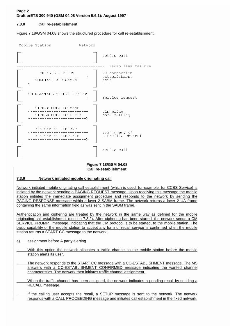
Page 2Draft prETS 300 940 (GSM 04.08 Version 5.6.1): August 1997
7.3.8 Call re-establishment
Figure 7.18/GSM 04.08 shows the structured procedure for call re-establishment.
Mobile Station Network
HF FI
G G DFWLYH FDOO
G G
JF FK
-------------------------------------- radio link failureHF FI
G &+$11(/ 5(48(67 G 55 FRQQHFWLRQ
G �������������������������! G HVWDEOLVKPHQW
G ,00(',$7( $66,*10(17 G �02�
G ������������������������� G
JF FK
HF FI
G &0 5((67$%/,6+0(17 5(48(67 G
G �������������������������! G 6HUYLFH UHTXHVW
JF FK
HF FI
G &,3+HU 02'H &200$1' G
G �������������������������� G &LSKHULQJ
G &,3+(5 02'( &203/(7( G PRGH VHWWLQJ
G �������������������������! G
JF FK
HF FI
G $66,*10(17 &200$1' G
G �������������������������� G DVVLJQPHQW RI
G $66,*10(17 &203/(7( G D WUDIILF FKDQQHO
G �������������������������! G
JF FK
HF FI
G G DFWLYH FDOO
G G
JF FK
Figure 7.18/GSM 04.08Call re-establishment
7.3.9 Network initiated mobile originating call
Network initiated mobile originating call establishment (which is used, for example, for CCBS Service) isinitiated by the network sending a PAGING REQUEST message. Upon receiving this message the mobilestation initiates the immediate assignment procedure and responds to the network by sending thePAGING RESPONSE message within a layer 2 SABM frame. The network returns a layer 2 UA framecontaining the same information field as was sent in the SABM frame.
Authentication and ciphering are treated by the network in the same way as defined for the mobileoriginating call establishment (section 7.3.2). After ciphering has been started, the network sends a CMSERVICE PROMPT message, indicating that the CM protocol is to be started, to the mobile station. Thebasic capability of the mobile station to accept any form of recall service is confirmed when the mobilestation returns a START CC message to the network.
a) assignment before A party alerting
With this option the network allocates a traffic channel to the mobile station before the mobilestation alerts its user.
The network responds to the START CC message with a CC-ESTABLISHMENT message. The MSanswers with a CC-ESTABLISHMENT CONFIRMED message indicating the wanted channelcharacteristics. The network then initiates traffic channel assignment.
When the traffic channel has been assigned, the network indicates a pending recall by sending aRECALL message.
If the calling user accepts the recall, a SETUP message is sent to the network. The networkresponds with a CALL PROCEEDING message and initiates call establishment in the fixed network.
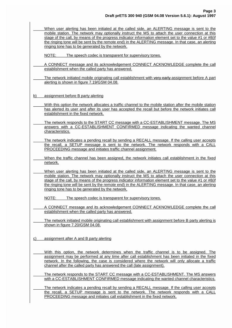
Page 3Draft prETS 300 940 (GSM 04.08 Version 5.6.1): August 1997
When user alerting has been initiated at the called side, an ALERTING message is sent to themobile station. The network may optionally instruct the MS to attach the user connection at thisstage of the call, by means of the progress indicator information element set to the value #1 or #8(ifthe ringing tone will be sent by the remote end) in the ALERTING message. In that case, an alertingringing tone has to be generated by the network.
NOTE: The speech codec is transparent for supervisory tones.
A CONNECT message and its acknowledgement CONNECT ACKNOWLEDGE complete the callestablishment when the called party has answered.
The network initiated mobile originating call establishment with very early assignment before A partalerting is shown in figure 7.19/GSM 04.08.
b) assignment before B party alerting
With this option the network allocates a traffic channel to the mobile station after the mobile stationhas alerted its user and after its user has accepted the recall but before the network initiates callestablishment in the fixed network.
The network responds to the START CC message with a CC-ESTABLISHMENT message. The MSanswers with a CC-ESTABLISHMENT CONFIRMED message indicating the wanted channelcharacteristics.
The network indicates a pending recall by sending a RECALL message. If the calling user acceptsthe recall, a SETUP message is sent to the network. The network responds with a CALLPROCEEDING message and initiates traffic channel assignment.
When the traffic channel has been assigned, the network initiates call establishment in the fixednetwork.
When user alerting has been initiated at the called side, an ALERTING message is sent to themobile station. The network may optionally instruct the MS to attach the user connection at thisstage of the call, by means of the progress indicator information element set to the value #1 or #8(ifthe ringing tone will be sent by the remote end) in the ALERTING message. In that case, an alertingringing tone has to be generated by the network.
NOTE: The speech codec is transparent for supervisory tones.
A CONNECT message and its acknowledgement CONNECT ACKNOWLEDGE complete the callestablishment when the called party has answered.
The network initiated mobile originating call establishment with assignment before B party alerting isshown in figure 7.20/GSM 04.08.
c) assignment after A and B party alerting
With this option, the network determines when the traffic channel is to be assigned. Theassignment may be performed at any time after call establishment has been initiated in the fixednetwork. In the following, the case is considered where the network will only allocate a trafficchannel after the called party has answered the call (late assignment).
The network responds to the START CC message with a CC-ESTABLISHMENT. The MS answerswith a CC-ESTABLISHMENT CONFIRMED message indicating the wanted channel characteristics.
The network indicates a pending recall by sending a RECALL message. If the calling user acceptsthe recall, a SETUP message is sent to the network. The network responds with a CALLPROCEEDING message and initiates call establishment in the fixed network.

Page 4Draft prETS 300 940 (GSM 04.08 Version 5.6.1): August 1997
As in a) and b) an ALERTING message is sent to the mobile station when user alerting has beeninitiated at the called side. If the ringing tone is needed, it has to be generated locally at the mobilestation as no traffic channel is allocated. When the called party has answered, the network willinitiate the channel assignment procedure in order to allocate a traffic channel to the mobile station.Once the channel assignment has been completed the network will send a CONNECT message tothe mobile station. The MS attaches then the user connection. The CONNECT ACKNOWLEDGEmessage will complete the call setup.
The network initiated mobile originating call establishment with early assignment after A and B partyalerting is shown in figure 7.21/GSM 04.08.
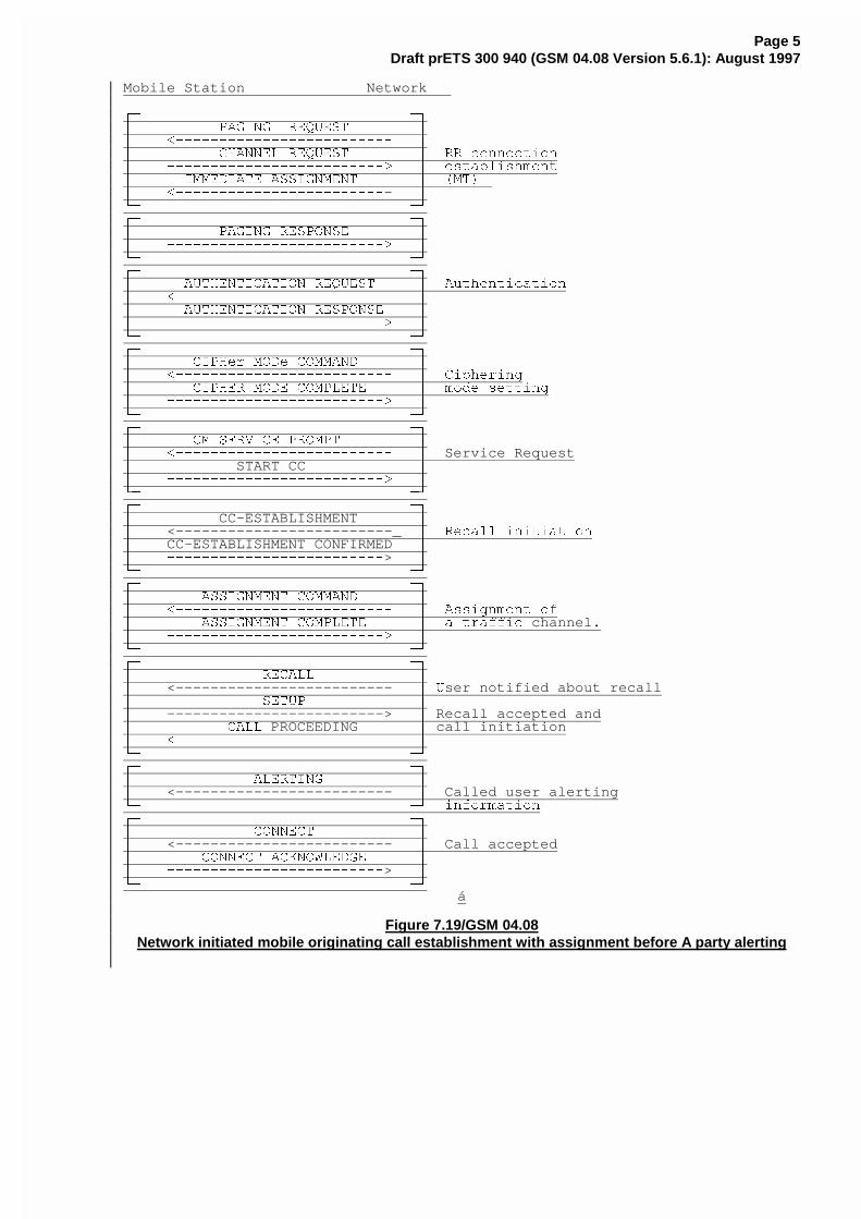
Page 5Draft prETS 300 940 (GSM 04.08 Version 5.6.1): August 1997
Mobile Station Network
HF FI
G 3$*,1* 5(48(67 G
G �������������������������� G
G &+$11(/ 5(48(67 G 55 FRQQHFWLRQ
G �������������������������! G HVWDEOLVKPHQW
G ,00(',$7( $66,*10(17 G �07� G �������������������������- GJF FK
HF FI
G 3$*,1* 5(63216( G
G �������������������������! G
JF FKHF FI
G $87+(17,&$7,21 5(48(67 G $XWKHQWLFDWLRQ
G �������������������������� G
G $87+(17,&$7,21 5(63216( G
G �������������������������! GJF FK
HF FI
G &,3+HU 02'H &200$1' G
G �������������������������� G &LSKHULQJ
G &,3+(5 02'( &203/(7( G PRGH VHWWLQJ
G �������������������������! GJF FK
HF FIG &0 6(59,&( 352037 G
G �������������������������� G Service RequestG START CC GG �������������������������! GJF FK
HF FI
G CC-ESTABLISHMENT GG <-------------------------_ G 5HFDOO LQLWLDWLRQ
G CC-ESTABLISHMENT CONFIRMED GG �������������������������> GJF FK
HF FI
G $66,*10(17 &200$1' GG �������������������������� G $VVLJQPHQW RI
G $66,*10(17 &203/(7( G D WUDIILF channel.G �������������������������! GJF FK
HF FI
G 5(&$// G
G <------------------------- G 8ser notified about recallG 6(783 G
G -------------------------> G Recall accepted andG &$// PROCEEDING G call initiationG �������������������������� G
JF FKHF FI
G $/(57,1* G
G <------------------------- G Called user alertingJF FK LQIRUPDWLRQ
HF FI
G &211(&7 G
G <------------------------- G Call acceptedG &211(&7 $&.12:/('*( G
G �������������������������> GJF FK
á
Figure 7.19/GSM 04.08Network initiated mobile originating call establishment with assignment before A party alerting
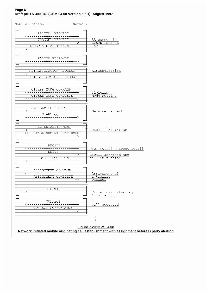
Page 6Draft prETS 300 940 (GSM 04.08 Version 5.6.1): August 1997
Mobile Station Network
HF FI
G 3$*,1* 5(48(67 G
G �������������������������� G
G &+$11(/ 5(48(67 G 55 FRQQHFWLRQ
G �������������������������! G HVWDEOLVKPHQW
G ,00(',$7( $66,*10(17 G �07� G �������������������������� G
JF FK
HF FI
G 3$*,1* 5(63216( G
G �����������������������--> GJF FK
HF FI
G $87+(17,&$7,21 5(48(67 G $XWKHQWLFDWLRQ
G �������������������������� G
G $87+(17,&$7,21 5(63216( G
G �������������������������! G
JF FK
HF FI
G &,3+HU 02'H &200$1' G
G �������������������������� G &LSKHULQJ
G &,3+(5 02'( &203/(7( G PRGH VHWWLQJ
G �������������������������! G
JF FKHF FI
G &0 6(59,&( 352037 G
G �������������������������� G 6HUYLFH 5HTXHVW
G 67$57 && G
G �������������������������! G
JF FK
HF FI
G CC-ESTABLISHMENT GG ��������������������������B G 5HFDOO LQLWLDWLRQ
G CC-ESTABLISHMENT CONFIRMED GG �������������������������! G
JF FK
HF FI
G RECALL GG �������������������������� G 8VHU QRWLILHG about recallG 6(783 G
G �������������������������! G 5HFDOO DFFHSWHG DQG
G &$// 352&((',1* G FDOO LQLWLDWLRQ
G �������������������������� G
JF FK
HF FI
G $66,*10(17 &200$1' G
G �������������������������� G $VVLJQPHQW RI
G $66,*10(17 &203/(7( G D WUDIILF
G ������������������������-> G FKDQQHO
JF FK
HF FI
G $/(57,1* G
G �������������������������� G &DOOHG XVHU DOHUWLQJ
JF FK LQIRUPDWLRQ
HF FI
G &211(&7 G
G �������������������������� G &DOO DFFHSWHG
G &211(&7 $&.12:/('*( G
G �������������������������! G
JF FK
áá
Figure 7.20/GSM 04.08Network initiated mobile originating call establishment with assignment before B party alerting
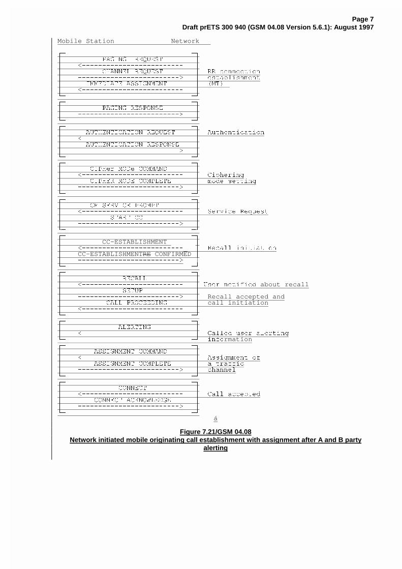
Page 7Draft prETS 300 940 (GSM 04.08 Version 5.6.1): August 1997
Mobile Station Network
HF FI
G 3$*,1* 5(48(67 G
G �������������������������� G
G &+$11(/ 5(48(67 G 55 FRQQHFWLRQ
G �������������������������! G HVWDEOLVKPHQW
G ,00(',$7( $66,*10(17 G �07� G �������������������������� G
JF FK
HF FI
G 3$*,1* 5(63216( G
G -------------------------> GJF FK
HF FI
G $87+(17,&$7,21 5(48(67 G $XWKHQWLFDWLRQ
G �������������������������� G
G $87+(17,&$7,21 5(63216( G
G �������������������������! G
JF FK
HF FI
G &,3+HU 02'H &200$1' G
G �������������������������� G &LSKHULQJ
G &,3+(5 02'( &203/(7( G PRGH VHWWLQJ
G �������������������������! G
JF FKHF FI
G &0 6(59,&( 352037 G
G �������������������������� G 6HUYLFH 5HTXHVW
G 67$57 && G
G �������������������������! G
JF FK
HF FI
G CC-ESTABLISHMENT GG ��������������������������B G 5HFDOO LQLWLDWLRQ
G CC-ESTABLISHMENTRE CONFIRMED GG �������������������������! |JF FK
HF FIG 5(&$// G
G �������������������������� G 8VHU QRWLILHG about recallG 6(783 G
G �������������������������! G Recall accepted andG &$// 352&((',1* G call initiationG �������������������������� G
JF FK
HF FI
G $/(57,1* G
G �������������������������� G &DOOHG XVHU DOHUWLQJ
JF FK LQIRrmationHF FI
G $66,*10(17 &200$1' G
G �������������������������� G $VVLJQPHQW RI
G $66,*10(17 &203/(7( G D WUDIILF
G �������������������������! G FKDQQHO
JF FK
HF FI
G &211(&7 G
G �������������������������� G &DOO DFFHSWHG
G &211(&7 $&.12:/('*( G
G �������������������������! G
JF FK
á
Figure 7.21/GSM 04.08Network initiated mobile originating call establishment with assignment after A and B party
alerting
ETSI STC SMG 2/3 WPA SMG3 TDoc 97A284Sophia Antipolis, France10-14/11/97
CHANGE REQUEST No. A232r2
Technical Specification GSM 04.08 version 5.6.1
Status at SMG [ ]: Approved [ ] Rejected [ ] Postponed [ ]
Phase 1: [ ] Phase 2: [ ] Phase 2+: [x] Work item: CCBS
Other phase(s) affected: [ ] If yes, linked CR(s):
Proposed change affects: SIM [ ] ME [ X ] Network [ X ]
Source: SMG3 Ericsson / Vodafone Date: 05/11/97
Subject: Call Control timers for CCBS recall
Category: F - Correction [ ]
A - Corresponds to a Phase 2 correction [ ]
B - Addition of Feature [ ]
C - Functional modification of Feature [X]
D - Editorial modification [ ]
Reason for change:
The CCBS recall Call Control timers need to be defined in section 11.3.
Note that MM and RR do not have any CCBS specific timers.
Sections affected, and additional explanation of details of change (if needed):
See appended pages.
Attached revised pages: yes
Page(s): .
If other core Specifications are affected, necessary (and attached) Joint CRs:
Affects (possibly): MS Test Specifications [y] BSS Test Specs [n] O&M Specifications [ ]
Attached CRs?: no
Cross Phase Compatibility:
Change affects operation of: Phase 1 MS in Phase 2(+) NW [N] Phase 2(+) MS in Phase 1 NW [N]:
Change affects operation of: Phase 1 SIM in Phase 2(+) ME[N] Phase 2(+) SIM in Phase 1 ME [N]
Other comments:
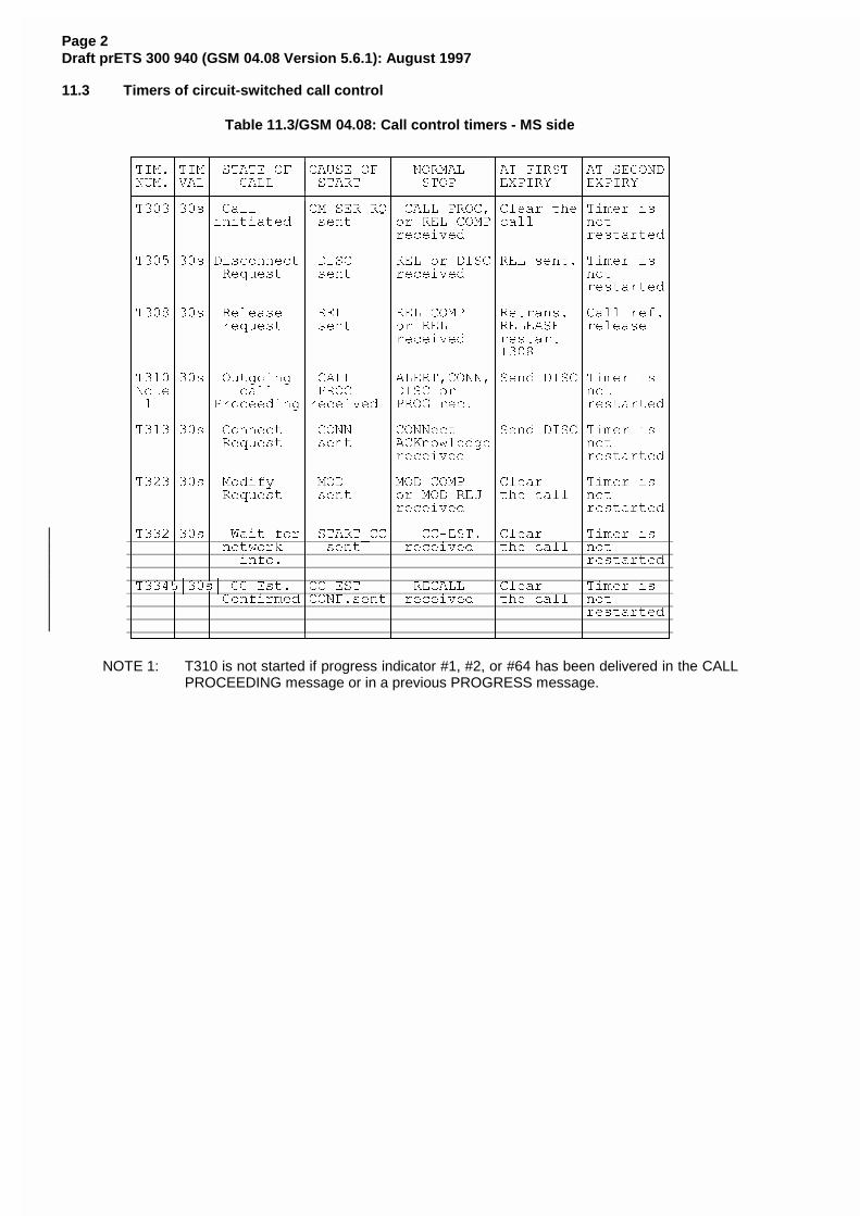
Page 2Draft prETS 300 940 (GSM 04.08 Version 5.6.1): August 1997
11.3 Timers of circuit-switched call control
Table 11.3/GSM 04.08: Call control timers - MS side
HFFFFNFFFNFFFFFFFFFFNFFFFFFFFFNFFFFFFFFFFFNFFFFFFFFFNFFFFFFFFFI
G7,0�G7,0G 67$7( 2) G&$86( 2) G 1250$/ G$7 ),567 G$7 6(&21'GG180�G9$/G &$// G 67$57 G 6723 G(;3,5< G(;3,5< G
LFFFFPFFFPFFFFFFFFFFPFFFFFFFFFPFFFFFFFFFFFPFFFFFFFFFPFFFFFFFFFM
G7���G��VG &DOO G&0 6(5 54G &$// 352&�G&OHDU WKHG7LPHU LV G
G G GLQLWLDWHG G VHQW GRU 5(/ &203GFDOO GQRW G
G G G G GUHFHLYHG G GUHVWDUWHGGG G G G G G G G
G7���G��VG'LVFRQQHFWG ',6& G5(/ RU ',6&G5(/ VHQW�G7LPHU LV G
G G G 5HTXHVW G VHQW GUHFHLYHG G GQRW G
G G G G G G GUHVWDUWHGGG G G G G G G G
G7���G��VG 5HOHDVH G 5(/ G5(/ &203 G5HWUDQV� G&DOO UHI�GG G G UHTXHVW G VHQW GRU 5(/ G5(/($6( GUHOHDVH G
G G G G GUHFHLYHG GUHVWDUW G G
G G G G G G7��� G G
G G G G G G G G
G7���G��VG 2XWJRLQJ G &$// G$/(57�&211�G6HQG ',6&G7LPHU LV G
G1RWHG G FDOO G 352& G',6& RU G GQRW G
G � G G3URFHHGLQJGUHFHLYHG G352* UHF� G GUHVWDUWHGGG G G G G G G G
G7���G��VG &RQQHFW G &211 G&211HFW G6HQG ',6&G7LPHU LV G
G G G 5HTXHVW G VHQW G$&.QRZOHGJHG GQRW G
G G G G GUHFHLYHG G GUHVWDUWHGGG G G G G G G G
G7���G��VG 0RGLI\ G 02' G02' &203 G&OHDU G7LPHU LV G
G G G 5HTXHVW G VHQW GRU 02' 5(- GWKH FDOO GQRW G
G G G G GUHFHLYHG G GUHVWDUWHGGG G G G G G G G
G7���G��VG :DLW IRUG 67$57B&&G &&�(67� G&OHDU G7LPHU LV G
G G G QHWZRUN G VHQW G UHFHLYHG GWKH FDOO GQRW G
G G G LQIR� G G G GUHVWDUWHGGG G G G G G G G
G7����G��VG &&�(VW� G&&�(67 G 5(&$// G&OHDU G7LPHU LV G
G G G &RQILUPHGG&21)�VHQWG UHFHLYHG GWKH FDOO GQRW G
G G G G G G GUHVWDUWHGGG G G G G G G G
JFFFFOFFFOFFFFFFFFFFOFFFFFFFFFOFFFFFFFFFFFOFFFFFFFFFOFFFFFFFFFK
NOTE 1: T310 is not started if progress indicator #1, #2, or #64 has been delivered in the CALLPROCEEDING message or in a previous PROGRESS message.
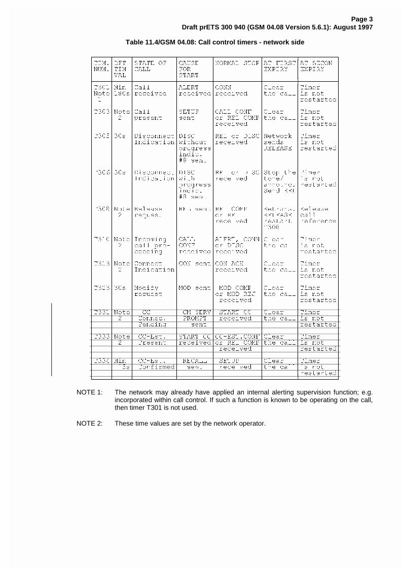
Page 3Draft prETS 300 940 (GSM 04.08 Version 5.6.1): August 1997
Table 11.4/GSM 04.08: Call control timers - network side
HFFFFNFFFFNFFFFFFFFFFNFFFFFFFFNFFFFFFFFFFFNFFFFFFFFNFFFFFFFFFI
G7,0�G')7 G67$7( 2) G&$86( G1250$/ 6723G$7 ),567G$7 6(&21 G
G180�G7,0 G&$// G)25 G G(;3,5< G(;3,5< G
G G9$/ G G67$57 G G G G
LFFFFPFFFFPFFFFFFFFFFPFFFFFFFFPFFFFFFFFFFFPFFFFFFFFPFFFFFFFFFM
G7���G0LQ G&DOO G$/(57 G&211 G&OHDU G7LPHU G
G1RWHG���VGUHFHLYHG GUHFHLYHGGUHFHLYHG GWKH FDOOGLV QRW G
G � G G G G G GUHVWDUWHGGG G G G G G G G
G7���G1RWHG&DOO G6(783 G&$// &21) G&OHDU G7LPHU G
G G � GSUHVHQW GVHQW GRU 5(/ &203GWKH FDOOGLV QRW G
G G G G GUHFHLYHG G GUHVWDUWHGGG G G G G G G G
G7���G��V G'LVFRQQHFWG',6& G5(/ RU ',6&G1HWZRUN G7LPHU G
G G G,QGLFDWLRQGZLWKRXW GUHFHLYHG GVHQGV GLV QRW G
G G G GSURJUHVVG G5(/($6( GUHVWDUWHGGG G G GLQGLF� G G G G
G G G G�� VHQW G G G G
G G G G G G G G
G7���G��V G'LVFRQQHFWG',6& G5(/ RU ',6&G6WRS WKHG7LPHU G
G G G,QGLFDWLRQGZLWK GUHFHLYHG GWRQH� GLV QRW G
G G G GSURJUHVVG GDQQRXQF�GUHVWDUWHGGG G G GLQGLF� G G6HQG 5(/G G
G G G G�� VHQW G G G G
G G G G G G G G
G7���G1RWHG5HOHDVH G5(/ VHQWG5(/ &203 G5HWUDQV�G5HOHDVH G
G G � GUHTXHVW G GRU 5(/ G5(/($6( GFDOO G
G G G G GUHFHLYHG GUHVWDUW GUHIHUHQFHGG G G G G G7��� G G
G G G G G G G G
G7���G1RWHG,QFRPLQJ G&$// G$/(57� &211G&OHDU G7LPHU G
G G � GFDOO SUR� G&21) GRU ',6& GWKH FDOOGLV QRW G
G G GFHHGLQJ GUHFHLYHGGUHFHLYHG G GUHVWDUWHGGG G G G G G G G
G7���G1RWHG&RQQHFW G&21 VHQWG&21 $&. G&OHDU G7LPHU G
G G � G,QGLFDWLRQG GUHFHLYHG GWKH FDOOGLV QRW G
G G G G G G GUHVWDUWHGGG G G G G G G G
G7���G��V G0RGLI\ G02' VHQWG 02' &203 G&OHDU G7LPHU G
G G GUHTXHVW G GRU 02' 5(- GWKH FDOOGLV QRW G
G G G G G UHFHLYHG G GUHVWDUWHGGG G G G G G G G
G7���G1RWHG && G &0�6(59G 67$57 && G&OHDU G7LPHU G
G G 2 G &RQQHF� G 352037 G UHFHLYHG GWKH FDOOGLV QRW G
G G G 3HQGLQJ G VHQW G G GUHVWDUWHGGG G G G G G G G
G7���G1RWHG &&�(VW� G67$57 &&G&&�(67�&21)G&OHDU G7LPHU G
G G � G 3UHVHQW GUHFHLYHGGRU 5(/ &203GWKH FDOOGLV QRW G
G G G G G UHFHLYHG G GUHVWDUWHGGG G G G G G G G
G7���G0LQ G &&�(VW� G 5(&$// G 6(783 G&OHDU G7LPHU G
G G ��VG &RQfirmedG VHQW G UHFHLYHG GWKH FDOOGLV QRW G
G G G G G G GUHVWDUWHGGJFFFFOFFFFOFFFFFFFFFFOFFFFFFFFOFFFFFFFFFFFOFFFFFFFFOFFFFFFFFFK
NOTE 1: The network may already have applied an internal alerting supervision function; e.g.incorporated within call control. If such a function is known to be operating on the call,then timer T301 is not used.
NOTE 2: These time values are set by the network operator.
ETSI STC SMG 2/3 WPA SMG3 TDoc 97A358Sophia Antipolis, France10-14/11/97
CHANGE REQUEST No. A 235 r1
Technical Specification GSM 04.08 version 5.6.1
Status at SMG [ ]: Approved [ ] Rejected [ ] Postponed [ ]
Phase 1: [ ] Phase 2: [ ] Phase 2+: [x] Work item: CCBS
Other phase(s) affected: [ ] If yes, linked CR(s):
Proposed change affects: SIM [ ] ME [ X ] Network [ X ]
Source: SMG3 Date: 1997 August 29
Subject: Indication of CCBS possible
Category: F - Correction [ ]
A - Corresponds to a Phase 2 correction [ ]
B - Addition of Feature [X]
C - Functional modification of Feature [ ]
D - Editorial modification [ ]
Reason for change:
For the CCBS supplementary service it is required, that a CCBS possible indication can be sent to themobile station in case the call setup fails due to busy subscriber.
Sections affected, and additional explanation of details of change (if needed):
See appended pages.
Attached revised pages:
Page(s): .
If other core Specifications are affected, necessary (and attached) Joint CRs:
Affects(possibly): MS Test Specifications [y] BSS Test Specifications[ ] O&M Specifications [ ]
Attached CRs?: no
Cross Phase Compatibility:
Change affects operation of: Phase 1 MS in Phase 2(+) NW [ ] Phase 2(+) MS in Phase 1 NW [ ]:
Change affects operation of: Phase 1 SIM in Phase 2(+) ME[ ] Phase 2(+) SIM in Phase 1 ME [ ]
Other comments:
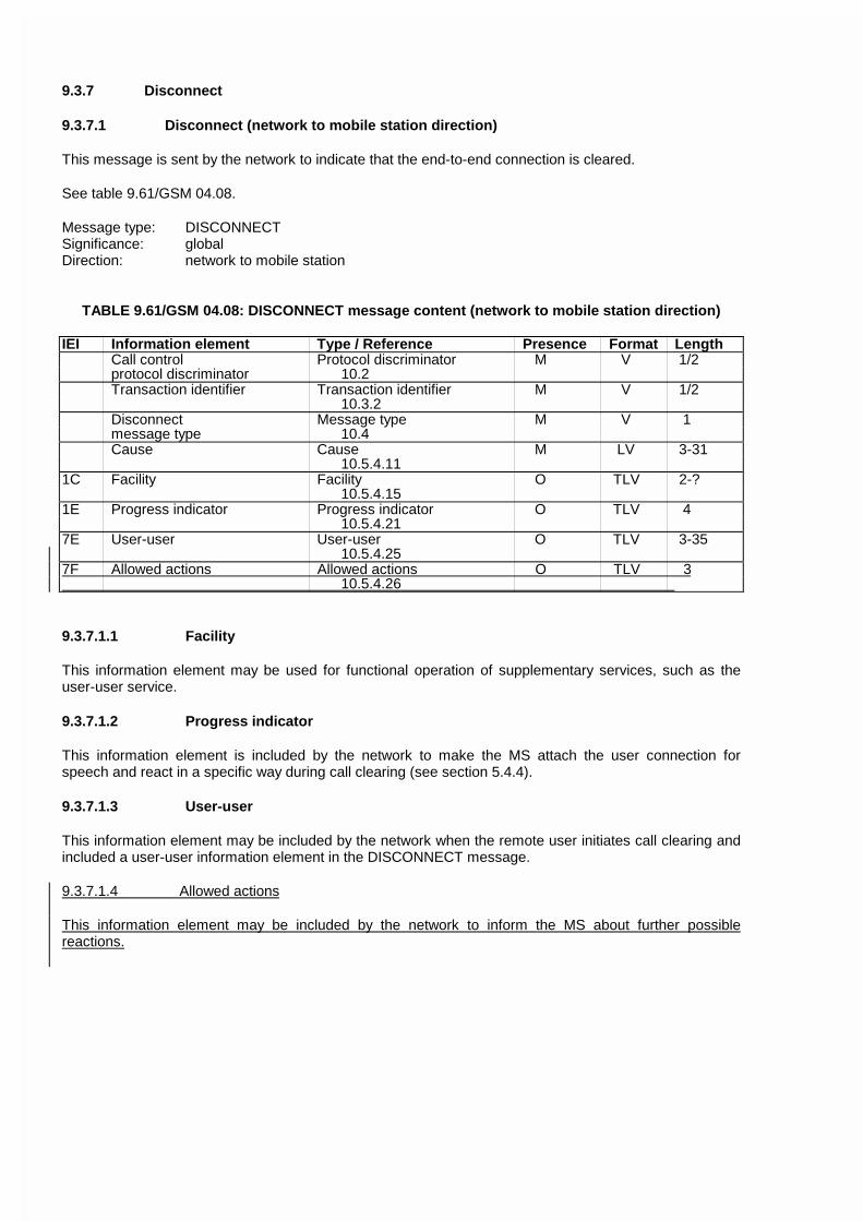
9.3.7 Disconnect
9.3.7.1 Disconnect (network to mobile station direction)
This message is sent by the network to indicate that the end-to-end connection is cleared.
See table 9.61/GSM 04.08.
Message type: DISCONNECTSignificance: globalDirection: network to mobile station
TABLE 9.61/GSM 04.08: DISCONNECT message content (network to mobile station direction)
IEI Information element Type / Reference Presence Format LengthCall control Protocol discriminator M V 1/2protocol discriminator 10.2Transaction identifier Transaction identifier M V 1/2
10.3.2Disconnect Message type M V 1message type 10.4Cause Cause M LV 3-31
10.5.4.111C Facility Facility O TLV 2-?
10.5.4.151E Progress indicator Progress indicator O TLV 4
10.5.4.217E User-user User-user O TLV 3-35
10.5.4.257F Allowed actions Allowed actions O TLV 3 10.5.4.26
9.3.7.1.1 Facility
This information element may be used for functional operation of supplementary services, such as theuser-user service.
9.3.7.1.2 Progress indicator
This information element is included by the network to make the MS attach the user connection forspeech and react in a specific way during call clearing (see section 5.4.4).
9.3.7.1.3 User-user
This information element may be included by the network when the remote user initiates call clearing andincluded a user-user information element in the DISCONNECT message.
9.3.7.1.4 Allowed actions
This information element may be included by the network to inform the MS about further possiblereactions.
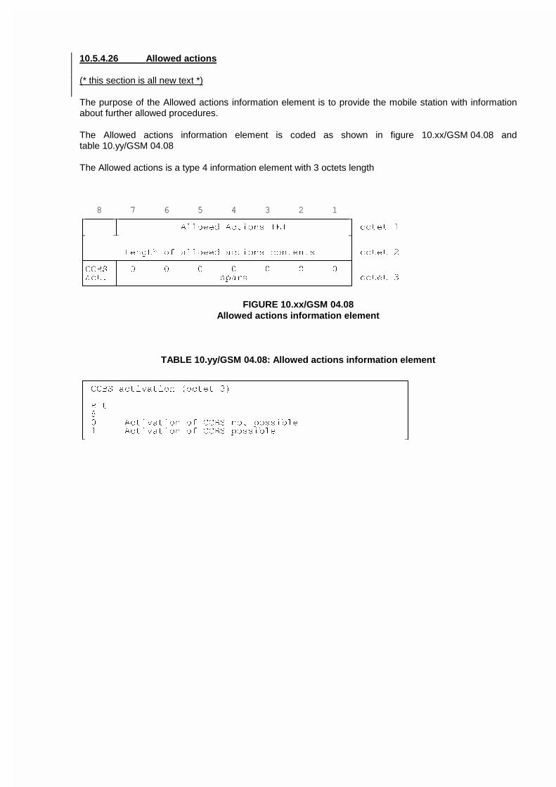
10.5.4.26 Allowed actions
(* this section is all new text *)
The purpose of the Allowed actions information element is to provide the mobile station with informationabout further allowed procedures.
The Allowed actions information element is coded as shown in figure 10.xx/GSM 04.08 andtable 10.yy/GSM 04.08
The Allowed actions is a type 4 information element with 3 octets length
8 7 6 5 4 3 2 1HFFFFFNFFFFFFFFFFFFFFFFFFFFFFFFFFFFFFFFFFFFFFFFFI
G G $OORZHG $FWLRQV ,(, G RFWHW �LFFFFFOFFFFFFFFFFFFFFFFFFFFFFFFFFFFFFFFFFFFFFFFFM
G G
G /HQJWK RI DOORZHG DFWLRQV FRQWHQWV G RFWHW �LFFFFFNFFFFFFFFFFFFFFFFFFFFFFFFFFFFFFFFFFFFFFFFFM
G&&%6 G � � � � � � � G
GDFW� G VSDUH G RFWHW �JFFFFFOFFFFFFFFFFFFFFFFFFFFFFFFFFFFFFFFFFFFFFFFFK
FIGURE 10.xx/GSM 04.08Allowed actions information element
TABLE 10.yy/GSM 04.08: Allowed actions information element
HFFFFFFFFFFFFFFFFFFFFFFFFFFFFFFFFFFFFFFFFFFFFFFFFFFFFFFFFFI
G &&%6 DFWLYDWLRQ �RFWHW �� G
G G
G %LW G
G � G
G � $FWLYDWLRQ RI &&%6 QRW SRVVLEOH G
G � $FWLYDWLRQ RI &&%6 SRVVLEOH G
JFFFFFFFFFFFFFFFFFFFFFFFFFFFFFFFFFFFFFFFFFFFFFFFFFFFFFFFFFK
ETSI STC SMG2/3 WPA SMG 3 TDoc 97A397Sophia Antipolis, France10-14/11/97 revised SMG 3 TDoc 97A281
CHANGE REQUEST No. A199r6
Technical Specification GSM 04.08 version 5.6.1
Status at SMG [ ]: Approved [ ] Rejected [ ] Postponed [ ]
Phase 1: [ ] Phase 2: [ ] Phase 2+: [x] Work item: CCBS
Other phase(s) affected: [ ] If yes, linked CR(s):
Proposed change affects: SIM [ ] ME [ X ] Network [ X ]
Source: SMG3 Date: 05/11/97
Subject: Messages and IEs for CCBS
Category: F - Correction [ ]
A - Corresponds to a Phase 2 correction [ ]
B - Addition of Feature [ ]
C - Functional modification of Feature [X]
D - Editorial modification [ ]
Reason for change:
Messages and IEs are needed for CCBS.
Sections affected, and additional explanation of details of change (if needed):
See appended pages.
Attached revised pages:
Page(s): .
If other core Specifications are affected, necessary (and attached) Joint CRs:
Affects (possibly): MS Test Specifications [y] BSS Test Specifications[n]
O&M Specifications [ ]
Attached CRs?: no
Cross Phase Compatibility:
Change affects operation of: Phase 1 MS in Phase 2(+) NW [ ] Phase 2(+) MS in Phase 1 NW [y]
:The bit in Classmark 2 requires aCR to phase 2 ETR 09.90 (but not

phase 2+ ETR 09.90).
Change affects operation of: Phase 1 SIM in Phase 2(+) ME[ ] Phase 2(+) SIM in Phase 1 ME [ ]
Other comments:
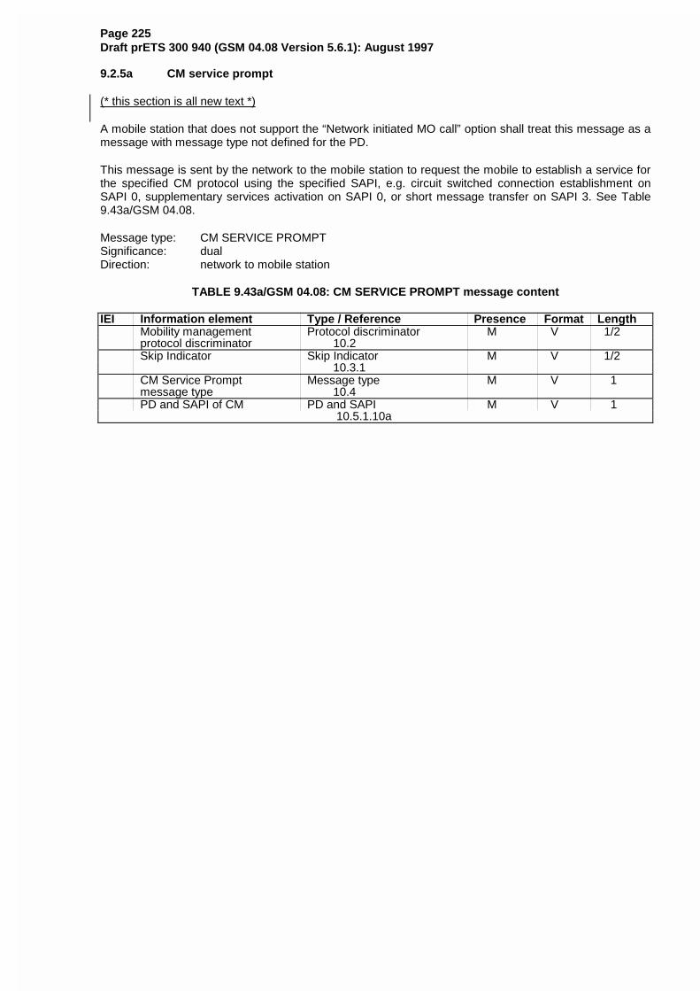
Page 225Draft prETS 300 940 (GSM 04.08 Version 5.6.1): August 1997
9.2.5a CM service prompt
(* this section is all new text *)
A mobile station that does not support the “Network initiated MO call” option shall treat this message as amessage with message type not defined for the PD.
This message is sent by the network to the mobile station to request the mobile to establish a service forthe specified CM protocol using the specified SAPI, e.g. circuit switched connection establishment onSAPI 0, supplementary services activation on SAPI 0, or short message transfer on SAPI 3. See Table9.43a/GSM 04.08.
Message type: CM SERVICE PROMPTSignificance: dualDirection: network to mobile station
TABLE 9.43a/GSM 04.08: CM SERVICE PROMPT message content
IEI Information element Type / Reference Presence Format LengthMobility management Protocol discriminator M V 1/2protocol discriminator 10.2Skip Indicator Skip Indicator M V 1/2
10.3.1CM Service Prompt Message type M V 1message type 10.4PD and SAPI of CM PD and SAPI M V 1
10.5.1.10a
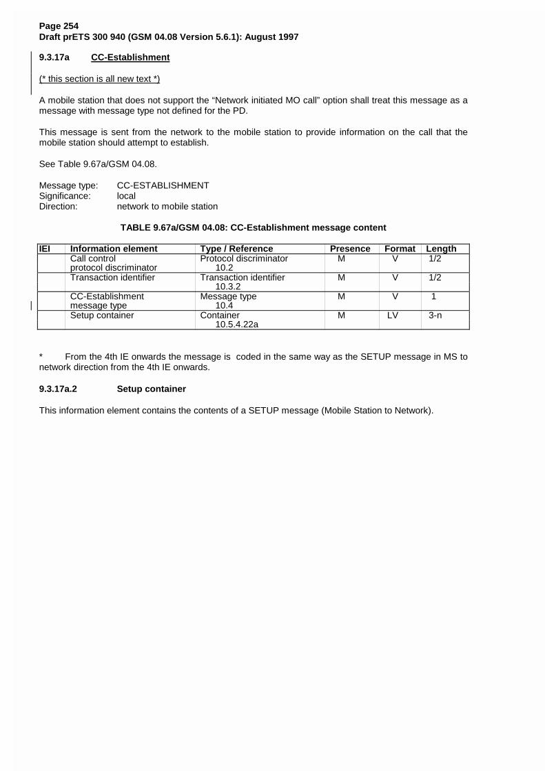
Page 254Draft prETS 300 940 (GSM 04.08 Version 5.6.1): August 1997
9.3.17a CC-Establishment
(* this section is all new text *)
A mobile station that does not support the “Network initiated MO call” option shall treat this message as amessage with message type not defined for the PD.
This message is sent from the network to the mobile station to provide information on the call that themobile station should attempt to establish.
See Table 9.67a/GSM 04.08.
Message type: CC-ESTABLISHMENTSignificance: localDirection: network to mobile station
TABLE 9.67a/GSM 04.08: CC-Establishment message content
IEI Information element Type / Reference Presence Format LengthCall control Protocol discriminator M V 1/2protocol discriminator 10.2Transaction identifier Transaction identifier M V 1/2
10.3.2CC-Establishment Message type M V 1message type 10.4Setup container Container M LV 3-n
10.5.4.22a
* From the 4th IE onwards the message is coded in the same way as the SETUP message in MS tonetwork direction from the 4th IE onwards.
9.3.17a.2 Setup container
This information element contains the contents of a SETUP message (Mobile Station to Network).
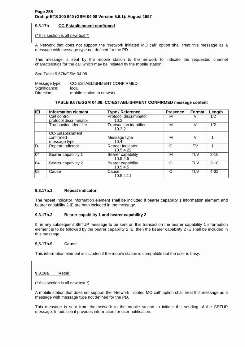
Page 255Draft prETS 300 940 (GSM 04.08 Version 5.6.1): August 1997
9.3.17b CC-Establishment confirmed
(* this section is all new text *)
A Network that does not support the “Network initiated MO call” option shall treat this message as amessage with message type not defined for the PD.
This message is sent by the mobile station to the network to indicate the requested channelcharacteristics for the call which may be initiated by the mobile station .
See Table 9.67b/GSM 04.08.
Message type: CC-ESTABLISHMENT CONFIRMEDSignificance: localDirection: mobile station to network
TABLE 9.67b/GSM 04.08: CC-ESTABLISHMENT CONFIRMED message content
IEI Information element Type / Reference Presence Format LengthCall control Protocol discriminator M V 1/2protocol discriminator 10.2Transaction identifier Transaction identifier M V 1/2
10.3.2CC-Establishment
confirmed Message type M V 1message type 10.4
D- Repeat Indicator Repeat Indicator C TV 1 10.5.4.22
04 Bearer capability 1 Bearer capability M TLV 3-10 10.5.4.5
04 Bearer capability 2 Bearer capability O TLV 3-10 10.5.4.5
08 Cause Cause O TLV 4-32 10.5.4.11
9.3.17b.1 Repeat indicator
The repeat indicator information element shall be included if bearer capability 1 information element andbearer capability 2 IE are both included in the message.
9.3.17b.2 Bearer capability 1 and bearer capability 2
If, in any subsequent SETUP message to be sent on this transaction the bearer capability 1 informationelement is to be followed by the bearer capability 2 IE, then the bearer capability 2 IE shall be included inthis message.
9.3.17b.9 Cause
This information element is included if the mobile station is compatible but the user is busy.
9.3.18a Recall
(* this section is all new text *)
A mobile station that does not support the “Network initiated MO call” option shall treat this message as amessage with message type not defined for the PD.
This message is sent from the network to the mobile station to initiate the sending of the SETUPmessage. In addition it provides information for user notification.
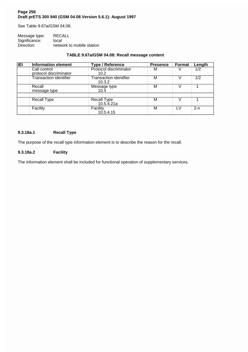
Page 256Draft prETS 300 940 (GSM 04.08 Version 5.6.1): August 1997
See Table 9.67a/GSM 04.08.
Message type: RECALLSignificance: localDirection: network to mobile station
TABLE 9.67a/GSM 04.08: Recall message content
IEI Information element Type / Reference Presence Format LengthCall control Protocol discriminator M V 1/2protocol discriminator 10.2Transaction identifier Transaction identifier M V 1/2
10.3.2Recall Message type M V 1message type 10.4
Recall Type Recall Type M V 1 10.5.4.21a
Facility Facility M LV 2-n 10.5.4.15
9.3.18a.1 Recall Type
The purpose of the recall type information element is to describe the reason for the recall.
9.3.18a.2 Facility
The information element shall be included for functional operation of supplementary services.
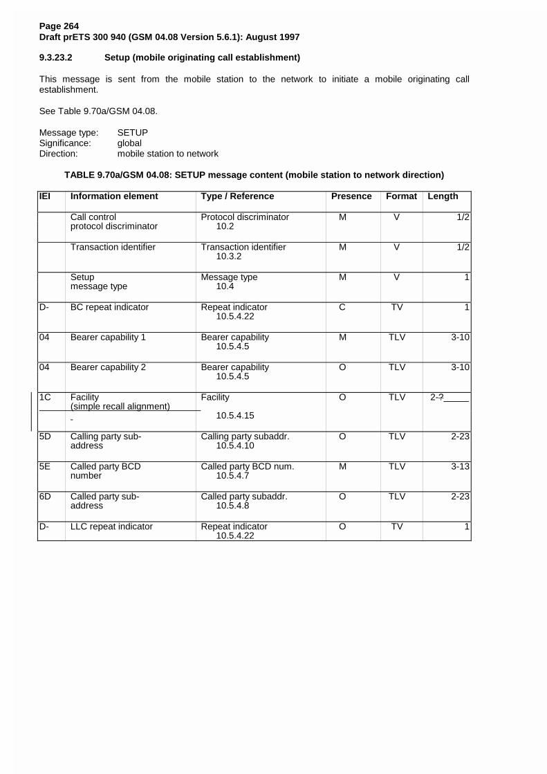
Page 264Draft prETS 300 940 (GSM 04.08 Version 5.6.1): August 1997
9.3.23.2 Setup (mobile originating call establishment)
This message is sent from the mobile station to the network to initiate a mobile originating callestablishment.
See Table 9.70a/GSM 04.08.
Message type: SETUPSignificance: globalDirection: mobile station to network
TABLE 9.70a/GSM 04.08: SETUP message content (mobile station to network direction)
IEI Information element Type / Reference Presence Format Length
Call control Protocol discriminator M V 1/2protocol discriminator 10.2
Transaction identifier Transaction identifier M V 1/2 10.3.2
Setup Message type M V 1message type 10.4
D- BC repeat indicator Repeat indicator C TV 1 10.5.4.22
04 Bearer capability 1 Bearer capability M TLV 3-10 10.5.4.5
04 Bearer capability 2 Bearer capability O TLV 3-10 10.5.4.5
1C Facility Facility O TLV 2-? (simple recall alignment)
10.5.4.15
5D Calling party sub- Calling party subaddr. O TLV 2-23address 10.5.4.10
5E Called party BCD Called party BCD num. M TLV 3-13number 10.5.4.7
6D Called party sub- Called party subaddr. O TLV 2-23address 10.5.4.8
D- LLC repeat indicator Repeat indicator O TV 1 10.5.4.22
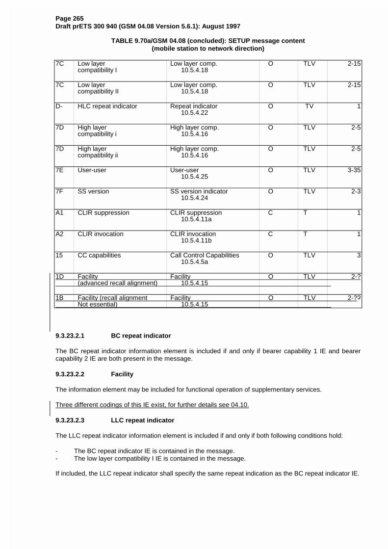
Page 265Draft prETS 300 940 (GSM 04.08 Version 5.6.1): August 1997
TABLE 9.70a/GSM 04.08 (concluded): SETUP message content(mobile station to network direction)
7C Low layer Low layer comp. O TLV 2-15compatibility I 10.5.4.18
7C Low layer Low layer comp. O TLV 2-15compatibility II 10.5.4.18
D- HLC repeat indicator Repeat indicator O TV 1 10.5.4.22
7D High layer High layer comp. O TLV 2-5compatibility i 10.5.4.16
7D High layer High layer comp. O TLV 2-5compatibility ii 10.5.4.16
7E User-user User-user O TLV 3-35 10.5.4.25
7F SS version SS version indicator O TLV 2-3 10.5.4.24
A1 CLIR suppression CLIR suppression C T 1 10.5.4.11a
A2 CLIR invocation CLIR invocation C T 1 10.5.4.11b
15 CC capabilities Call Control Capabilities O TLV 3 10.5.4.5a
1D Facility Facility O TLV 2-? (advanced recall alignment) 10.5.4.15
1B Facility (recall alignment Facility O TLV 2-?? Not essential) 10.5.4.15
9.3.23.2.1 BC repeat indicator
The BC repeat indicator information element is included if and only if bearer capability 1 IE and bearercapability 2 IE are both present in the message.
9.3.23.2.2 Facility
The information element may be included for functional operation of supplementary services.
Three different codings of this IE exist, for further details see 04.10.
9.3.23.2.3 LLC repeat indicator
The LLC repeat indicator information element is included if and only if both following conditions hold:
- The BC repeat indicator IE is contained in the message.- The low layer compatibility I IE is contained in the message.
If included, the LLC repeat indicator shall specify the same repeat indication as the BC repeat indicator IE.
Page 266Draft prETS 300 940 (GSM 04.08 Version 5.6.1): August 1997
9.3.23.2.4 Low layer compatibility I
The information element is included in the MS-to-network direction when the calling MS wants to pass lowlayer compatibility information to the called user.
9.3.23.2.5 Low layer compatibility II
Included if and only if the LLC repeat indicator information element is contained in the message.
9.3.23.2.6 HLC repeat indicator
The HLC repeat indicator information element is included if and only if both following conditions hold:
- The BC repeat indicator IE is contained in the message.- The high layer compatibility i IE is contained in the message.
If included, the HLC repeat indicator shall specify the same repeat indication as the BC repeat indicator IE.
9.3.23.2.7 High layer compatibility i
The information element is included when the calling MS wants to pass high layer compatibility informationto the called user.
9.3.23.2.8 High layer compatibility ii
Included if and only if the HLC repeat indicator information element is contained in the message.
9.3.23.2.9 User-user
The information element is included in the calling mobile station to network direction when the callingmobile station wants to pass user information to the called remote user.
9.3.23.2.10 SS version
This information element shall not be included if no facility information element is present in thismessage.
This information element shall be included or excluded as defined in TS GSM 04.10. This informationelement should not be transmitted unless explicitly required by TS GSM 04.10.
9.3.23.2.11 CLIR suppression
The information element may be included by the MS (see TS GSM 04.81). If this information element isincluded the CLIR invocation IE shall not be included.
9.3.23.2.12 CLIR invocation
The information element may be included by the MS (see TS GSM 04.81). If this information element isincluded the CLIR suppression IE shall not be included.
9.3.23.2.13 CC Capabilities
This information element may be included by the mobile station to indicate its call control capabilities.
9.3.23a Start CC
(* this section is all new text *)
A Network that does not support the “Network initiated MO call” option shall treat this message as a
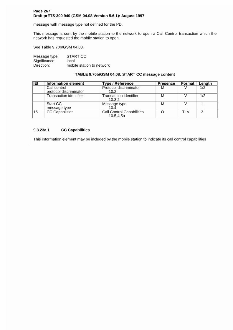
Page 267Draft prETS 300 940 (GSM 04.08 Version 5.6.1): August 1997
message with message type not defined for the PD.
This message is sent by the mobile station to the network to open a Call Control transaction which thenetwork has requested the mobile station to open.
See Table 9.70b/GSM 04.08.
Message type: START CCSignificance: localDirection: mobile station to network
TABLE 9.70b/GSM 04.08: START CC message content
IEI Information element Type / Reference Presence Format LengthCall control Protocol discriminator M V 1/2protocol discriminator 10.2Transaction identifier Transaction identifier M V 1/2
10.3.2Start CC Message type M V 1message type 10.4
15 CC Capabilities Call Control Capabilities O TLV 3 10.5.4.5a
9.3.23a.1 CC Capabilities
This information element may be included by the mobile station to indicate its call control capabilities
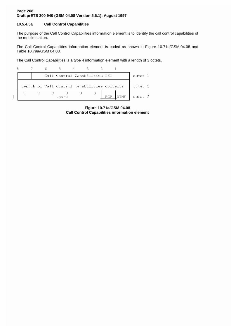
Page 268Draft prETS 300 940 (GSM 04.08 Version 5.6.1): August 1997
10.5.4.5a Call Control Capabilities
The purpose of the Call Control Capabilities information element is to identify the call control capabilities ofthe mobile station.
The Call Control Capabilities information element is coded as shown in Figure 10.71a/GSM 04.08 andTable 10.79a/GSM 04.08.
The Call Control Capabilities is a type 4 information element with a length of 3 octets.
8 7 6 5 4 3 2 1HFFFFFNFFFFFFFFFFFFFFFFFFFFFFFFFFFFFFFFFFFFFFFFFI
G G &DOO &RQWURO &DSDELOLWLHV ,(, G RFWHW �LFFFFFOFFFFFFFFFFFFFFFFFFFFFFFFFFFFFFFFFFFFFFFFFM
G G
G /HQJWK RI &DOO &RQWURO &DSDELOLWLHV FRQWHQWV G RFWHW �LFFFFFFFFFFFFFFFFFFFFFFFFFFFFFFFFFFFNFFFFFNFFFFFM
G � � � � � � G G G
G VSDUH G PCP GDTMF G RFWHW �JFFFFFFFFFFFFFFFFFFFFFFFFFFFFFFFFFFFOFFFFFOFFFFFK
Figure 10.71a/GSM 04.08Call Control Capabilities information element
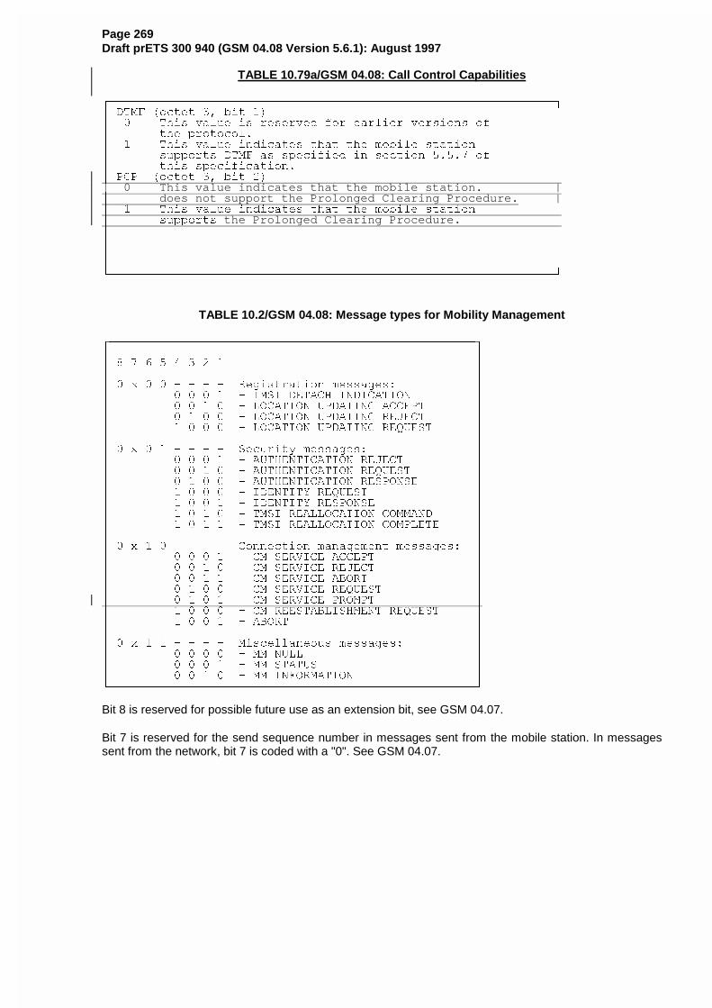
Page 269Draft prETS 300 940 (GSM 04.08 Version 5.6.1): August 1997
TABLE 10.79a/GSM 04.08: Call Control Capabilities
HFFFFFFFFFFFFFFFFFFFFFFFFFFFFFFFFFFFFFFFFFFFFFFFFFFFFFFFFFFFFFFI
G '70) �RFWHW �� ELW �� G
G � 7KLV YDOXH LV UHVHUYHG IRU HDUOLHU YHUVLRQV RI G
G WKH SURWRFRO� G
G � 7KLV YDOXH LQGLFDWHV WKDW WKH PRELOH VWDWLRQ G
G VXSSRUWV '70) DV VSHFLILHG LQ VHFWLRQ ����� RI G
G WKLV VSHFLILFDWLRQ� G
G 3&3 �RFWHW �� ELW �� G| 0 This value indicates that the mobile station. |G does not support the Prolonged Clearing Procedure. |G � 7KLV YDOXH LQGLFDWHV WKDW WKH PRELOH VWDWLRQ G
G VXSSRUWV the Prolonged Clearing Procedure. GG _G G
G G
G G
JFFFFFFFFFFFFFFFFFFFFFFFFFFFFFFFFFFFFFFFFFFFFFFFFFFFFFFFFFFFFFFK
TABLE 10.2/GSM 04.08: Message types for Mobility Management
HFFFFFFFFFFFFFFFFFFFFFFFFFFFFFFFFFFFFFFFFFFFFFFFFFFFI
G G
G � � � � � � � � G
G G
G � [ � � � � � � 5HJLVWUDWLRQ PHVVDJHV� G
G � � � � � ,06, '(7$&+ ,1',&$7,21 G
G � � � � � /2&$7,21 83'$7,1* $&&(37 G
G � � � � � /2&$7,21 83'$7,1* 5(-(&7 G
G � � � � � /2&$7,21 83'$7,1* 5(48(67 G
G G
G � [ � � � � � � 6HFXULW\ PHVVDJHV� G
G � � � � � $87+(17,&$7,21 5(-(&7 G
G � � � � � $87+(17,&$7,21 5(48(67 G
G � � � � � $87+(17,&$7,21 5(63216( G
G � � � � � ,'(17,7< 5(48(67 G
G � � � � � ,'(17,7< 5(63216( G
G � � � � � 706, 5($//2&$7,21 &200$1' G
G � � � � � 706, 5($//2&$7,21 &203/(7( G
G G
G � [ � � � � � � &RQQHFWLRQ PDQDJHPHQW PHVVDJHV� G
G � � � � � &0 6(59,&( $&&(37 G
G � � � � � &0 6(59,&( 5(-(&7 G
G � � � � � &0 6(59,&( $%257 G
G � � � � � &0 6(59,&( 5(48(67 G
G � � � � � &0 6(59,&( 352037 G
G � � � � � &0 5((67$%/,6+0(17 5(48(67 G
G � � � � � $%257 G
G G
G � [ � � � � � � 0LVFHOODQHRXV PHVVDJHV� G
G � � � � � 00 18// G
G � � � � � 00 67$786 G
G � � � � � 00 ,1)250$7,21 G
JFFFFFFFFFFFFFFFFFFFFFFFFFFFFFFFFFFFFFFFFFFFFFFFFFFFK
Bit 8 is reserved for possible future use as an extension bit, see GSM 04.07.
Bit 7 is reserved for the send sequence number in messages sent from the mobile station. In messagessent from the network, bit 7 is coded with a "0". See GSM 04.07.
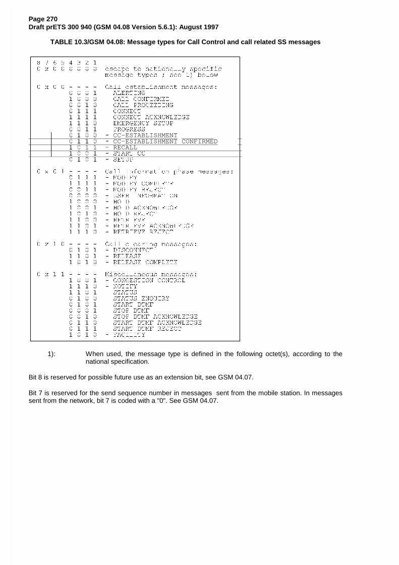
Page 270Draft prETS 300 940 (GSM 04.08 Version 5.6.1): August 1997
TABLE 10.3/GSM 04.08: Message types for Call Control and call related SS messages
HFFFFFFFFFFFFFFFFFFFFFFFFFFFFFFFFFFFFFFFFFFFFFFFFFFFI
G � � � � � � � � G
G � [ � � � � � � HVFDSH WR QDWLRQDOO\ VSHFLILF G
G PHVVDJH W\SHV � VHH �� EHORZ G
G G
G � [ � � � � � � &DOO HVWDEOLVKPHQW PHVVDJHV� G
G � � � � � $/(57,1* G
G � � � � � &$// &21),50(' G
G � � � � � &$// 352&((',1* G
G � � � � � &211(&7 G
G � � � � � &211(&7 $&.12:/('*( G
G � � � � � (0(5*(1&< 6(783 G
G � � � � � 352*5(66 G
G � � � � � CC-ESTABLISHMENT GG � � � � � CC-ESTABLISHMENT CONFIRMED GG � � 1 1 - RECALL GG � � � � � 67$57 && G
G � � � � � 6(783 G
G G
G � [ � � � � � � &DOO LQIRUPDWLRQ SKDVH PHVVDJHV� G
G � � � � � 02',)< G
G � � � � � 02',)< &203/(7( G
G � � � � � 02',)< 5(-(&7 G
G � � � � � 86(5 ,1)250$7,21 G
G � � � � � +2/' G
G � � � � � +2/' $&.12:/('*( G
G � � � � � +2/' 5(-(&7 G
G � � � � � 5(75,(9( G
G � � � � � 5(75,(9( $&.12:/('*( G
G � � � � � 5(75,(9( 5(-(&7 G
G G
G � [ � � � � � � &DOO FOHDULQJ PHVVDJHV� G
G � � � � � ',6&211(&7 G
G � � � � � 5(/($6( G
G � � � � � 5(/($6( &203/(7( G
G G
G � [ � � � � � � 0LVFHOODQHRXV PHVVDJHV� G
G � � � � � &21*(67,21 &21752/ G
G � � � � � 127,)< G
G � � � � � 67$786 G
G � � � � � 67$786 (148,5< G
G � � � � � 67$57 '70) G
G � � � � � 6723 '70) G
G � � � � � 6723 '70) $&.12:/('*( G
G � � � � � 67$57 '70) $&.12:/('*( G
G � � � � � 67$57 '70) 5(-(&7 G
G � � � � � )$&,/,7< G
JFFFFFFFFFFFFFFFFFFFFFFFFFFFFFFFFFFFFFFFFFFFFFFFFFFFK
1): When used, the message type is defined in the following octet(s), according to thenational specification.
Bit 8 is reserved for possible future use as an extension bit, see GSM 04.07.
Bit 7 is reserved for the send sequence number in messages sent from the mobile station. In messagessent from the network, bit 7 is coded with a "0". See GSM 04.07.
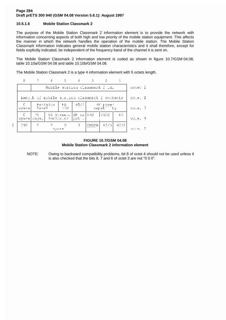
Page 284Draft prETS 300 940 (GSM 04.08 Version 5.6.1): August 1997
10.5.1.6 Mobile Station Classmark 2
The purpose of the Mobile Station Classmark 2 information element is to provide the network withinformation concerning aspects of both high and low priority of the mobile station equipment. This affectsthe manner in which the network handles the operation of the mobile station. The Mobile StationClassmark information indicates general mobile station characteristics and it shall therefore, except forfields explicitly indicated, be independent of the frequency band of the channel it is sent on.
The Mobile Station Classmark 2 information element is coded as shown in figure 10.7/GSM 04.08,table 10.10a/GSM 04.08 and table 10.10b/GSM 04.08.
The Mobile Station Classmark 2 is a type 4 information element with 5 octets length.
8 7 6 5 4 3 2 1HFFFFFNFFFFFFFFFFFFFFFFFFFFFFFFFFFFFFFFFFFFFFFFFI
G G 0RELOH VWDWLRQ FODVVPDUN � ,(, G RFWHW �LFFFFFOFFFFFFFFFFFFFFFFFFFFFFFFFFFFFFFFFFFFFFFFFM
G G
G /HQJWK RI PRELOH VWDWLRQ FODVVPDUN � FRQWHQWV G RFWHW �LFFFFFNFFFFFFFFFFFNFFFFFNFFFFFNFFFFFFFFFFFFFFFFFM
G � G 5HYLVLRQ G (6 G $���G 5) SRZHU G
GVSDUHG OHYHO G ,1' G G FDSDELOLW\ G RFWHW �LFFFFFPFFFFFNFFFFFOFFFFFPFFFFFPFFFFFNFFFFFNFFFFFM
G � G 36 G 66 6FUHHQ�G60 FDG9%6 G9*&6 G )& G
GVSDUHGFDSD�G ,QGLFDWRU GSDEL�G G G G RFWHW �LFFFFFPFFFFFOFFFFFFFFFFFOFFFFFPFFFFFPFFFFFPFFFFFM
G &0� G � � � � GCMSP0G $���G $���GG G VSDUH G G G G RFWHW �JFFFFFOFFFFFFFFFFFFFFFFFFFFFFFOFFFFFOFFFFFOFFFFFK
FIGURE 10.7/GSM 04.08Mobile Station Classmark 2 information element
NOTE: Owing to backward compatibility problems, bit 8 of octet 4 should not be used unless itis also checked that the bits 8, 7 and 6 of octet 3 are not "0 0 0".
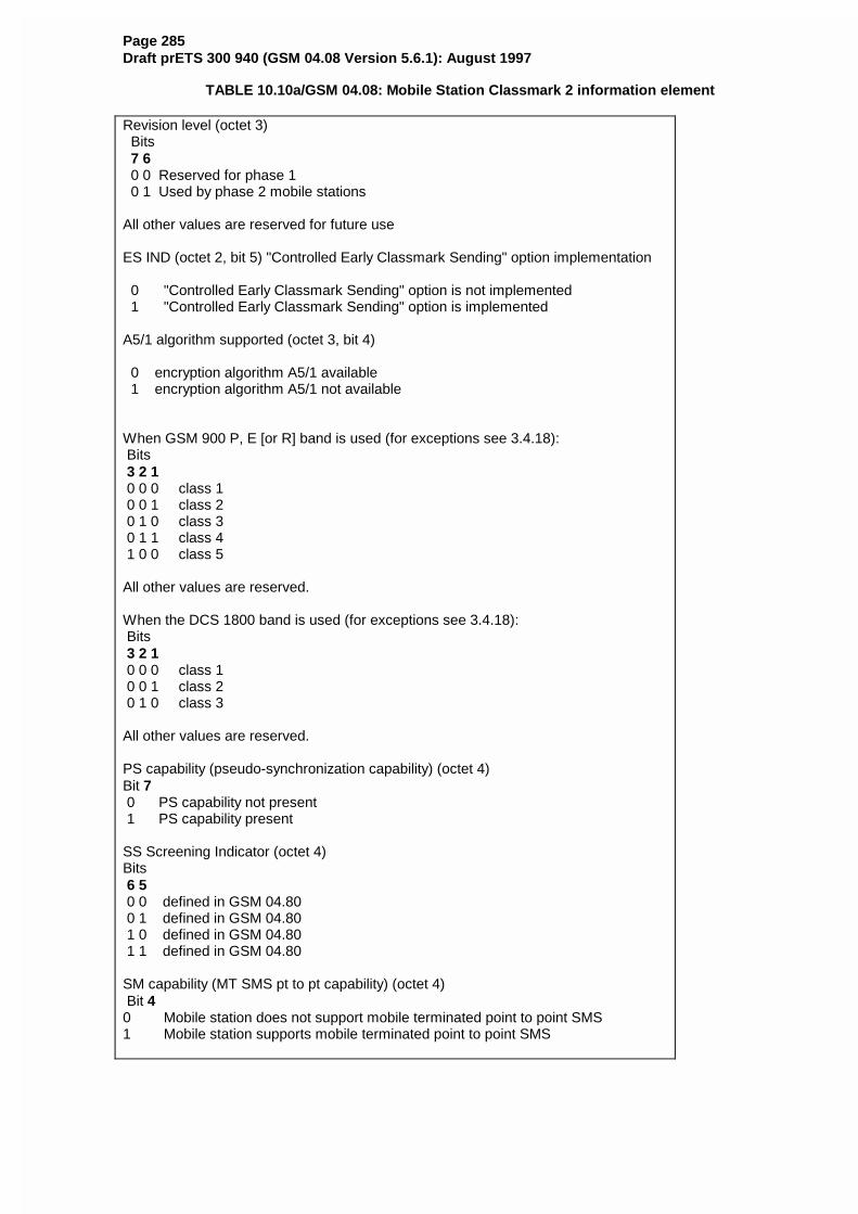
Page 285Draft prETS 300 940 (GSM 04.08 Version 5.6.1): August 1997
TABLE 10.10a/GSM 04.08: Mobile Station Classmark 2 information element
Revision level (octet 3) Bits 7 6 0 0 Reserved for phase 1 0 1 Used by phase 2 mobile stations
All other values are reserved for future use
ES IND (octet 2, bit 5) "Controlled Early Classmark Sending" option implementation
0 "Controlled Early Classmark Sending" option is not implemented 1 "Controlled Early Classmark Sending" option is implemented
A5/1 algorithm supported (octet 3, bit 4)
0 encryption algorithm A5/1 available 1 encryption algorithm A5/1 not available
When GSM 900 P, E [or R] band is used (for exceptions see 3.4.18): Bits 3 2 1 0 0 0 class 1 0 0 1 class 2 0 1 0 class 3 0 1 1 class 4 1 0 0 class 5
All other values are reserved.
When the DCS 1800 band is used (for exceptions see 3.4.18): Bits 3 2 1 0 0 0 class 1 0 0 1 class 2 0 1 0 class 3
All other values are reserved.
PS capability (pseudo-synchronization capability) (octet 4)Bit 7 0 PS capability not present 1 PS capability present
SS Screening Indicator (octet 4)Bits 6 5 0 0 defined in GSM 04.80 0 1 defined in GSM 04.80 1 0 defined in GSM 04.80 1 1 defined in GSM 04.80
SM capability (MT SMS pt to pt capability) (octet 4) Bit 40 Mobile station does not support mobile terminated point to point SMS1 Mobile station supports mobile terminated point to point SMS
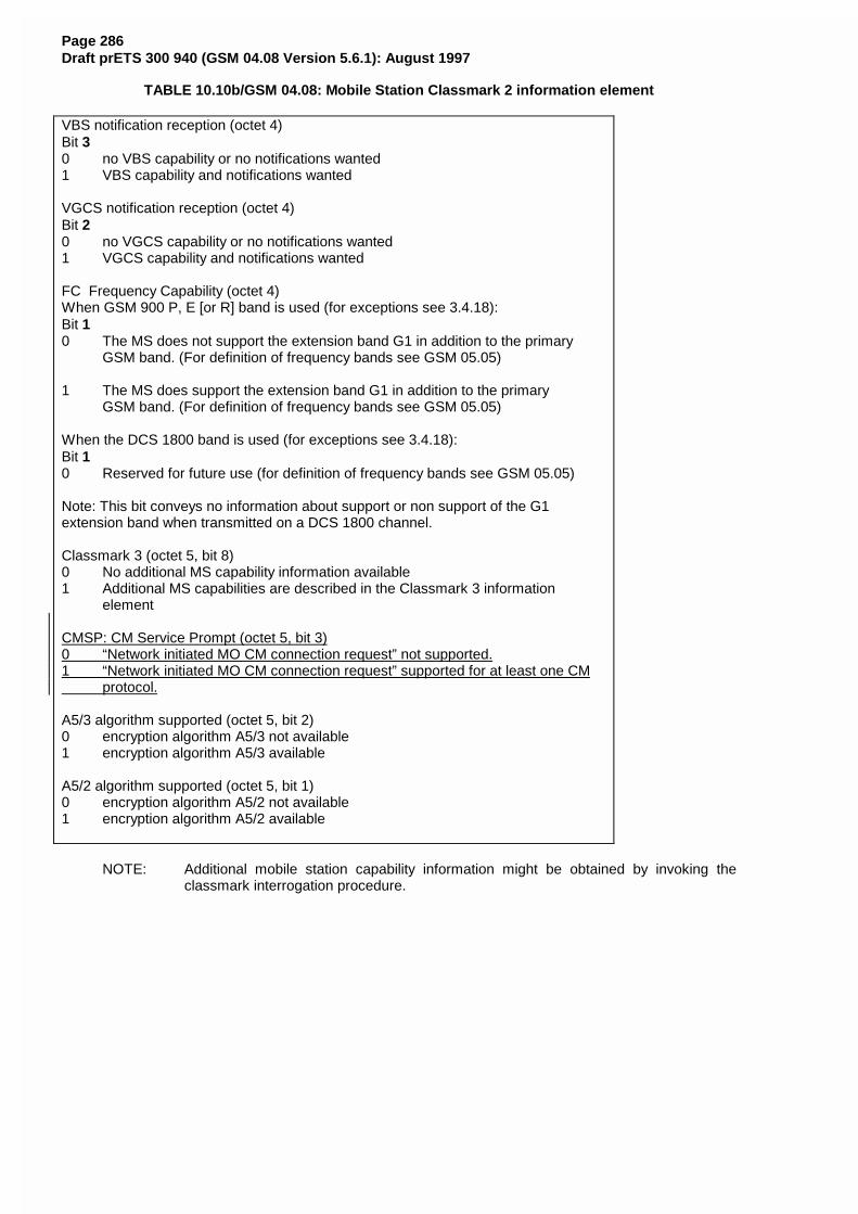
Page 286Draft prETS 300 940 (GSM 04.08 Version 5.6.1): August 1997
TABLE 10.10b/GSM 04.08: Mobile Station Classmark 2 information element
VBS notification reception (octet 4)Bit 30 no VBS capability or no notifications wanted1 VBS capability and notifications wanted
VGCS notification reception (octet 4)Bit 20 no VGCS capability or no notifications wanted1 VGCS capability and notifications wanted
FC Frequency Capability (octet 4)When GSM 900 P, E [or R] band is used (for exceptions see 3.4.18):Bit 10 The MS does not support the extension band G1 in addition to the primary
GSM band. (For definition of frequency bands see GSM 05.05)
1 The MS does support the extension band G1 in addition to the primaryGSM band. (For definition of frequency bands see GSM 05.05)
When the DCS 1800 band is used (for exceptions see 3.4.18):Bit 10 Reserved for future use (for definition of frequency bands see GSM 05.05)
Note: This bit conveys no information about support or non support of the G1extension band when transmitted on a DCS 1800 channel.
Classmark 3 (octet 5, bit 8)0 No additional MS capability information available1 Additional MS capabilities are described in the Classmark 3 information
element
CMSP: CM Service Prompt (octet 5, bit 3)0 “Network initiated MO CM connection request” not supported.1 “Network initiated MO CM connection request” supported for at least one CM protocol.
A5/3 algorithm supported (octet 5, bit 2)0 encryption algorithm A5/3 not available1 encryption algorithm A5/3 available
A5/2 algorithm supported (octet 5, bit 1)0 encryption algorithm A5/2 not available1 encryption algorithm A5/2 available
NOTE: Additional mobile station capability information might be obtained by invoking theclassmark interrogation procedure.
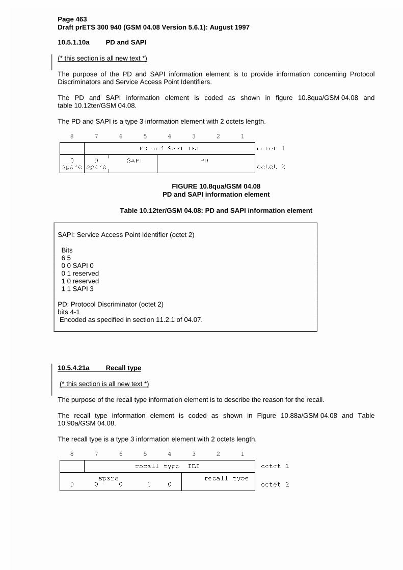
Page 463Draft prETS 300 940 (GSM 04.08 Version 5.6.1): August 1997
10.5.1.10a PD and SAPI
(* this section is all new text *)
The purpose of the PD and SAPI information element is to provide information concerning ProtocolDiscriminators and Service Access Point Identifiers.
The PD and SAPI information element is coded as shown in figure 10.8qua/GSM 04.08 andtable 10.12ter/GSM 04.08.
The PD and SAPI is a type 3 information element with 2 octets length.
8 7 6 5 4 3 2 1HFFFFFNFFFFFFFFFFFFFFFFFFFFFFFFFFFFFFFFFFFFFFFFFI
G G 3' DQG 6$3, ,(, GRFWHW �LFFFFFPFFFFFNFFFFFFFFFFFNFFFFFFFFFFFFFFFFFFFFFFFM
G � G � G 6$3, G 3' G
GVSDUHGVSDUHG G GRFWHW �JFFFFFOFFFFFOFFFFFFFFFFFOFFFFFFFFFFFFFFFFFFFFFFFK
FIGURE 10.8qua/GSM 04.08PD and SAPI information element
Table 10.12ter/GSM 04.08: PD and SAPI information element
SAPI: Service Access Point Identifier (octet 2)
Bits 6 5 0 0 SAPI 0 0 1 reserved 1 0 reserved 1 1 SAPI 3
PD: Protocol Discriminator (octet 2)bits 4-1 Encoded as specified in section 11.2.1 of 04.07.
10.5.4.21a Recall type
(* this section is all new text *)
The purpose of the recall type information element is to describe the reason for the recall.
The recall type information element is coded as shown in Figure 10.88a/GSM 04.08 and Table10.90a/GSM 04.08.
The recall type is a type 3 information element with 2 octets length.
8 7 6 5 4 3 2 1HFFFFFNFFFFFFFFFFFFFFFFFFFFFFFFFFFFFFFFFFFFFFFFFI
G G UHFDOO W\SH ,(, G RFWHW �LFFFFFOFFFFFFFFFFFFFFFFFFFFFFFNFFFFFFFFFFFFFFFFFM
G VSDUH G UHFDOO W\SH G
G � � � � � G G RFWHW �JFFFFFFFFFFFFFFFFFFFFFFFFFFFFFOFFFFFFFFFFFFFFFFFK

Page 464Draft prETS 300 940 (GSM 04.08 Version 5.6.1): August 1997
FIGURE 10.88a/GSM 04.08Recall type information element
TABLE 10.90a/GSM 04.08: Recall type information element
HFFFFFFFFFFFFFFFFFFFFFFFFFFFFFFFFFFFFFFFFFFFFFFFFFFFFFFFFFFFFFFI
G UHFDOO W\SH �RFWHW �� ELWV � WR �� G
G %LWV G
G � � � G
G � � � � &&%6 G
G � � � ` G
G WR `� VKDOO EH WUHDWHG DV &&%6 �LQWHQGHG IRU RWKHU G
G � � � ` VLPLODU W\SHV RI 5HFDOO� G
G � � � � UHVHUYHG G
JFFFFFFFFFFFFFFFFFFFFFFFFFFFFFFFFFFFFFFFFFFFFFFFFFFFFFFFFFFFFFFK
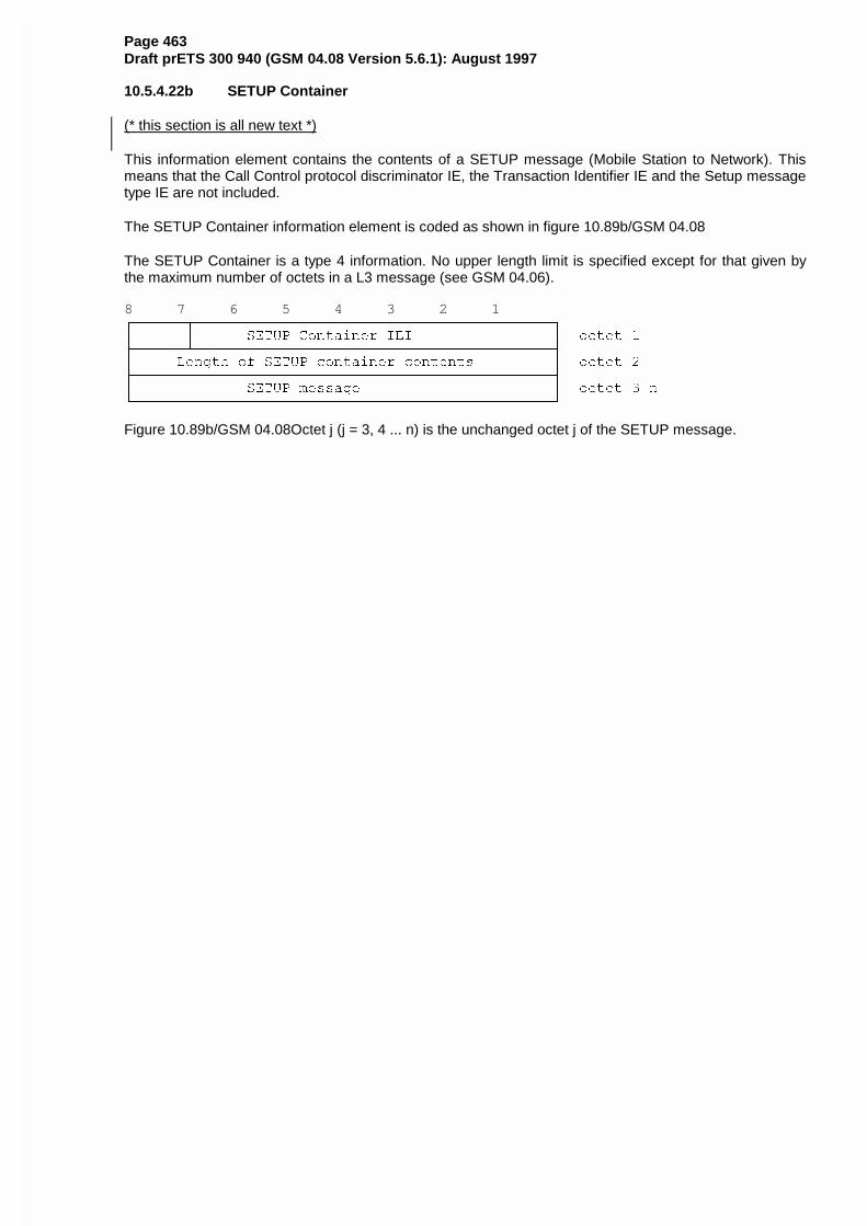
Page 463Draft prETS 300 940 (GSM 04.08 Version 5.6.1): August 1997
10.5.4.22b SETUP Container
(* this section is all new text *)
This information element contains the contents of a SETUP message (Mobile Station to Network). Thismeans that the Call Control protocol discriminator IE, the Transaction Identifier IE and the Setup messagetype IE are not included.
The SETUP Container information element is coded as shown in figure 10.89b/GSM 04.08
The SETUP Container is a type 4 information. No upper length limit is specified except for that given bythe maximum number of octets in a L3 message (see GSM 04.06).
8 7 6 5 4 3 2 1HFFFFFFNFFFFFFFFFFFFFFFFFFFFFFFFFFFFFFFFFFFFFFFFFI
G G 6(783 &RQWDLQHU ,(, G RFWHW �LFFFFFFOFFFFFFFFFFFFFFFFFFFFFFFFFFFFFFFFFFFFFFFFFM
G /HQJWK RI 6(783 FRQWDLQHU FRQWHQWV G RFWHW �LFFFFFFFFFFFFFFFFFFFFFFFFFFFFFFFFFFFFFFFFFFFFFFFFM
G 6(783 PHVVDJH G RFWHW ��QJFFFFFFFFFFFFFFFFFFFFFFFFFFFFFFFFFFFFFFFFFFFFFFFFK
Figure 10.89b/GSM 04.08Octet j (j = 3, 4 ... n) is the unchanged octet j of the SETUP message.
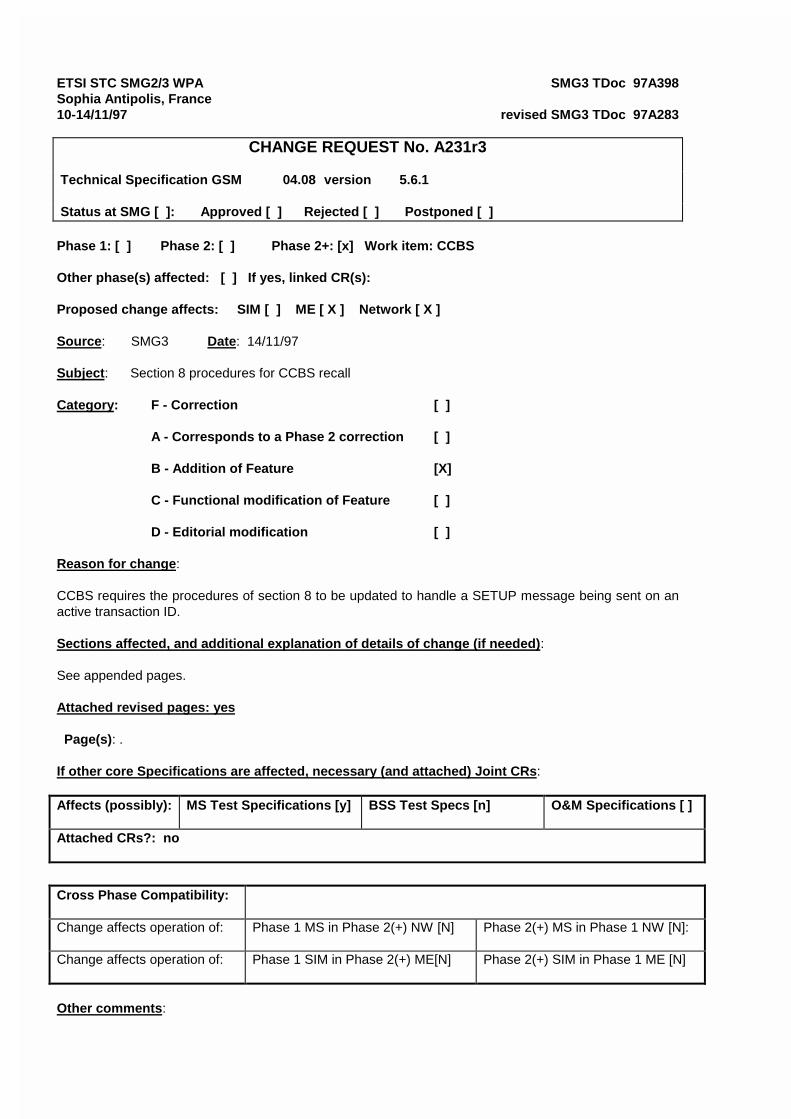
ETSI STC SMG2/3 WPA SMG3 TDoc 97A398Sophia Antipolis, France10-14/11/97 revised SMG3 TDoc 97A283
CHANGE REQUEST No. A231r3
Technical Specification GSM 04.08 version 5.6.1
Status at SMG [ ]: Approved [ ] Rejected [ ] Postponed [ ]
Phase 1: [ ] Phase 2: [ ] Phase 2+: [x] Work item: CCBS
Other phase(s) affected: [ ] If yes, linked CR(s):
Proposed change affects: SIM [ ] ME [ X ] Network [ X ]
Source: SMG3 Date: 14/11/97
Subject: Section 8 procedures for CCBS recall
Category: F - Correction [ ]
A - Corresponds to a Phase 2 correction [ ]
B - Addition of Feature [X]
C - Functional modification of Feature [ ]
D - Editorial modification [ ]
Reason for change:
CCBS requires the procedures of section 8 to be updated to handle a SETUP message being sent on anactive transaction ID.
Sections affected, and additional explanation of details of change (if needed):
See appended pages.
Attached revised pages: yes
Page(s): .
If other core Specifications are affected, necessary (and attached) Joint CRs:
Affects (possibly): MS Test Specifications [y] BSS Test Specs [n] O&M Specifications [ ]
Attached CRs?: no
Cross Phase Compatibility:
Change affects operation of: Phase 1 MS in Phase 2(+) NW [N] Phase 2(+) MS in Phase 1 NW [N]:
Change affects operation of: Phase 1 SIM in Phase 2(+) ME[N] Phase 2(+) SIM in Phase 1 ME [N]
Other comments:
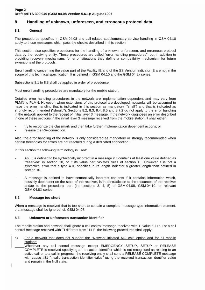
Page 2Draft prETS 300 940 (GSM 04.08 Version 5.6.1): August 1997
8 Handling of unknown, unforeseen, and erroneous protocol data
8.1 General
The procedures specified in GSM 04.08 and call-related supplementary service handling in GSM 04.10apply to those messages which pass the checks described in this section.
This section also specifies procedures for the handling of unknown, unforeseen, and erroneous protocoldata by the receiving entity. These procedures are called "error handling procedures", but in addition toproviding recovery mechanisms for error situations they define a compatibility mechanism for futureextensions of the protocols.
Error handling concerning the value part of the Facility IE and of the SS Version Indicator IE are not in thescope of this technical specification. It is defined in GSM 04.10 and the GSM 04.8x series.
Subsections 8.1 to 8.8 shall be applied in order of precedence.
Most error handling procedures are mandatory for the mobile station.
Detailed error handling procedures in the network are implementation dependent and may vary fromPLMN to PLMN. However, when extensions of this protocol are developed, networks will be assumed tohave the error handling that is indicated in this section as mandatory ("shall") and that is indicated asstrongly recommended ("should"). Sections 8.2, 8.3, 8.4, 8.5 and 8.7.2 do not apply to the error handlingin the network applied to the receipt of initial layer 3 message: If the network diagnoses an error describedin one of these sections in the initial layer 3 message received from the mobile station, it shall either:
- try to recognize the classmark and then take further implementation dependent actions; or- release the RR-connection.
Also, the error handling of the network is only considered as mandatory or strongly recommended whencertain thresholds for errors are not reached during a dedicated connection.
In this section the following terminology is used:
- An IE is defined to be syntactically incorrect in a message if it contains at least one value defined as"reserved" in section 10, or if its value part violates rules of section 10. However it is not asyntactical error that a type 4 IE specifies in its length indicator a greater length than defined insection 10.
- A message is defined to have semantically incorrect contents if it contains information which,possibly dependent on the state of the receiver, is in contradiction to the resources of the receiverand/or to the procedural part (i.e. sections 3, 4, 5) of GSM 04.08, GSM 04.10, or relevantGSM 04.8X series.
8.2 Message too short
When a message is received that is too short to contain a complete message type information element,that message shall be ignored, cf. GSM 04.07.
8.3 Unknown or unforeseen transaction identifier
The mobile station and network shall ignore a call control message received with TI value "111". For a callcontrol message received with TI different from "111", the following procedures shall apply:
a) For a network that does not support the “Network initiated MO call” option and for all mobilestations:
Whenever any call control message except EMERGENCY SETUP, SETUP or RELEASECOMPLETE is received specifying a transaction identifier which is not recognised as relating to anactive call or to a call in progress, the receiving entity shall send a RELEASE COMPLETE messagewith cause #81 "invalid transaction identifier value" using the received transaction identifier valueand remain in the Null state.
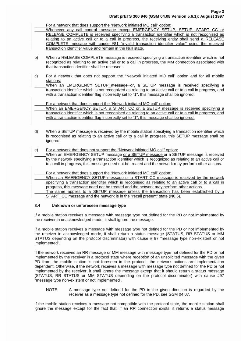
Page 3Draft prETS 300 940 (GSM 04.08 Version 5.6.1): August 1997
For a network that does support the “Network initiated MO call” option: Whenever any call control message except EMERGENCY SETUP, SETUP, START CC or
RELEASE COMPLETE is received specifying a transaction identifier which is not recognized asrelating to an active call or to a call in progress, the receiving entity shall send a RELEASECOMPLETE message with cause #81 "invalid transaction identifier value" using the receivedtransaction identifier value and remain in the Null state.
b) When a RELEASE COMPLETE message is received specifying a transaction identifier which is notrecognized as relating to an active call or to a call in progress, the MM connection associated withthat transaction identifier shall be released.
c) For a network that does not support the “Network initiated MO call” option and for all mobilestations:
When an EMERGENCY SETUP message or, a SETUP message is received specifying atransaction identifier which is not recognized as relating to an active call or to a call in progress, andwith a transaction identifier flag incorrectly set to "1", this message shall be ignored.
For a network that does support the “Network initiated MO call” option: When an EMERGENCY SETUP, a START CC or, a SETUP message is received specifying a
transaction identifier which is not recognised as relating to an active call or to a call in progress, andwith a transaction identifier flag incorrectly set to "1", this message shall be ignored.
d) When a SETUP message is received by the mobile station specifying a transaction identifier whichis recognised as relating to an active call or to a call in progress, this SETUP message shall beignored.
e) For a network that does not support the “Network initiated MO call” option: When an EMERGENCY SETUP message or a SETUP message or a SETUP message is received
by the network specifying a transaction identifier which is recognized as relating to an active call orto a call in progress, this message need not be treated and the network may perform other actions.
For a network that does support the “Network initiated MO call” option: When an EMERGENCY SETUP message or a START CC message is received by the network
specifying a transaction identifier which is recognised as relating to an active call or to a call inprogress, this message need not be treated and the network may perform other actions.
The same applies to a SETUP message unless the transaction has been established by aSTART_CC message and the network is in the “recall present” state (N0.6).
8.4 Unknown or unforeseen message type
If a mobile station receives a message with message type not defined for the PD or not implemented bythe receiver in unacknowledged mode, it shall ignore the message.
If a mobile station receives a message with message type not defined for the PD or not implemented bythe receiver in acknowledged mode, it shall return a status message (STATUS, RR STATUS or MMSTATUS depending on the protocol discriminator) with cause # 97 "message type non-existent or notimplemented".
If the network receives an RR message or MM message with message type not defined for the PD or notimplemented by the receiver in a protocol state where reception of an unsolicited message with the givenPD from the mobile station is not foreseen in the protocol, the network actions are implementationdependent. Otherwise, if the network receives a message with message type not defined for the PD or notimplemented by the receiver, it shall ignore the message except that it should return a status message(STATUS, RR STATUS or MM STATUS depending on the protocol discriminator) with cause #97"message type non-existent or not implemented".
NOTE: A message type not defined for the PD in the given direction is regarded by thereceiver as a message type not defined for the PD, see GSM 04.07.
If the mobile station receives a message not compatible with the protocol state, the mobile station shallignore the message except for the fact that, if an RR connection exists, it returns a status message
Page 4Draft prETS 300 940 (GSM 04.08 Version 5.6.1): August 1997
(STATUS, RR STATUS or MM STATUS depending on the protocol discriminator) with cause #98"Message type not compatible with protocol state".
If the network receives a message not compatible with the protocol state, the network actions areimplementation dependent.
8.5 Non-semantical mandatory information element errors
When on receipt of a message,
- an "imperative message part" error; or- a "missing mandatory IE" error
is diagnosed or when a message containing:
- a syntactically incorrect mandatory IE; or- an IE unknown in the message, but encoded as "comprehension required" (see section 10.5); or- an out of sequence IE encoded as "comprehension required" (see section 10.5)
is received,
Page 5Draft prETS 300 940 (GSM 04.08 Version 5.6.1): August 1997
- the mobile station shall proceed as follows:
When the message is not one of the messages listed in sections 8.5.1, 8.5.2, and 8.5.3, themobile station shall ignore the message except for the fact that, if an RR connection exists, itshall return a status message (STATUS, RR STATUS or MM STATUS depending on theprotocol discriminator) with cause # 96 "invalid mandatory information".
- the network shall proceed as follows:
When the message is not one of the message listed in section 8.5.3 b), c) or e), the networkshall either
- try to treat the message (the exact further actions are implementation dependent), or- ignore the message except that it should return a status message (STATUS, RR
STATUS or MM STATUS depending on the protocol discriminator) with cause # 96"invalid mandatory information".
8.5.1 Radio resource management
For the mobile station the following procedures shall apply:
a) If the message is a CHANNEL RELEASE message, the actions taken shall be the same asspecified in 3.5 "RR connection release".
b) If the message is a PARTIAL RELEASE message, the reactions of the MS are for further study.
8.5.2 Mobility management
No exceptional cases are described for mobility management messages.
8.5.3 Call control
a) If the message is a SETUP, EMERGENCY SETUP or a RELEASE message, a RELEASECOMPLETE message with cause # 96 "invalid mandatory information" shall be returned.
b) If the message is a DISCONNECT message, a RELEASE message shall be returned with causevalue # 96 "invalid mandatory information" and section 5.4. "call clearing" applies as normal.
c) If the message is a RELEASE COMPLETE message, it shall be treated as a normal RELEASECOMPLETE message.
d) If the message is a HOLD REJECT or RETRIEVE REJECT message, it shall be treated as anormal HOLD REJECT or RETRIEVE REJECT message.
e) If the message is a STATUS message and received by the network, a RELEASE COMPLETEmessage may be returned with cause value # 96 "invalid mandatory information".
8.6 Unknown and unforeseen IEs in the non-imperative message part
8.6.1 IEIs unknown in the message
The MS shall ignore all IEs unknown in a message which are not encoded as "comprehension required".
The network shall take the same approach.
8.6.2 Out of sequence IEs
The MS shall ignore all out of sequence IEs in a message which are not encoded as "comprehensionrequired".
The network should take the same approach.
Page 6Draft prETS 300 940 (GSM 04.08 Version 5.6.1): August 1997
8.6.3 Repeated IEs
If an information element with format T, TV, or TLV is repeated in a message in which repetition of theinformation element is not specified in section 9 of this technical specification, only the contents of theinformation element appearing first shall be handled and all subsequent repetitions of the informationelement shall be ignored. When repetition of information elements is specified, only the contents ofspecified repeated information elements shall be handled. If the limit on repetition of information elementsis exceeded, the contents of information elements appearing first up to the limit of repetitions shall behandled and all subsequent repetitions of the information element shall be ignored.
The network should follow the same procedures.
8.7 Non-imperative message part errors
This category includes:
- syntactically incorrect optional IEs;- conditional IE errors.
8.7.1 Syntactically incorrect optional IEs
The MS shall treat all optional IEs that are syntactically incorrect in a message as not present in themessage.
The network shall take the same approach.
8.7.2 Conditional IE errors
When the MS upon receipt of a message diagnoses a "missing conditional IE" error or an "unexpectedconditional IE" error or when it receives a message containing at least one syntactically incorrectconditional IE, it shall ignore the message except for the fact that, if an RR connection exists, it shallreturn a status message (STATUS, RR STATUS, or MM STATUS depending on the PD) with cause value# 100 "conditional IE error".
When the network receives a message and diagnose a "missing conditional IE" error or an "unexpectedconditional IE" error or when it receives a message containing at least one syntactically incorrectconditional IE, the network shall either
- try to treat the message (the exact further actions are implementation dependent), or- ignore the message except that it should return a status message (STATUS, RR STATUS or MM
STATUS depending on the protocol discriminator) with cause # 100 "conditional IE error".
8.8 Messages with semantically incorrect contents
When a message with semantically incorrect contents is received, the foreseen reactions of theprocedural part of GSM 04.08 (i.e. of sections 3, 4, 5) are performed. If however no such reactions arespecified, the MS shall ignore the message except for the fact that, if an RR connection exists, it returns astatus message (STATUS, RR STATUS, or MM STATUS depending on the PD) with cause value # 95"semantically incorrect message".
The network should follow the same procedure except that a status message is not normally transmitted.
Semantic checking of the Facility information element value part (defined in GSM 04.80) is the subject ofthe technical specifications GSM 04.10 and the GSM 04.8x series.
ETSI STC SMG3 WPA Tdoc SMG3 98A022
Sophia Antipolis, FRANCE
03 - 06 February 1998
CHANGE REQUEST No. 04.07-A14
Technical Specification GSM 04.07 version 5.2.0.
Submitted to SMG for approval without presentation ("non-strategic") [ X ]
with presentation ("strategic")[ ]
Status at SMG#25 [ ]: Approved [ ] Rejected [ ] Postponed [ ]
Phase 1: [ ] Phase 2: [ ] Phase 2+: [x] Work item: CCBS
Other phase(s) affected: [ ] If yes, linked CR(s):
Proposed change affects: SIM [ ] ME [ X ] Network [ ]
Source: SMG3 Date: 03 - 06 February 1998
Subject: Primitive MMXX_PROMPT_REJ added.
Category: F - Correction [ ]A - Corresponds to a Phase 2 correction [ ]B - Addition of Feature [ x ]C - Functional modification of Feature[ ]D - Editorial modification [ ]
Reason for change:
In a mobile station that supports “Network Initiated MO CM Connection Request” the CM entityidentified by the CM SERVICE PROMPT receives an indication of the completion of the MMconnection. If there is not any connection available in CM entity then CM SERVICE PROMPTREJECT is sent to MM for releasing the MM connection and sending STATUS message to thenetwork.
Sections affected, and additional explanation of details of change (if needed):
See appended pages.
If other core Specifications are affected, necessary (and attached) Joint CRs:
Affects (possibly): MS Test Specifications [ ] BSS Test Specifications [ ] O&M Specifications [ ]Attached CRs?:
Cross Phase Compatibility:Change affects operation of: Phase 1 MS in Phase 2(+) NW [ ] Phase 2(+) MS in Phase 1 NW [ ]
Change affects operation of: Phase 1 SIM in Phase 2(+) ME[ ] Phase 2(+) SIM in Phase 1 ME [ ]
Other comments:
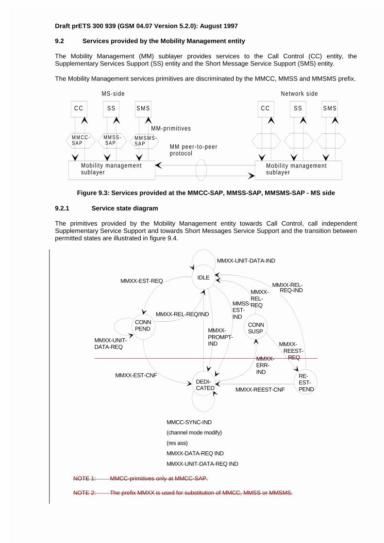
Draft prETS 300 939 (GSM 04.07 Version 5.2.0): August 1997
9.2 Services provided by the Mobility Management entity
The Mobility Management (MM) sublayer provides services to the Call Control (CC) entity, theSupplementary Services Support (SS) entity and the Short Message Service Support (SMS) entity.
The Mobility Management services primitives are discriminated by the MMCC, MMSS and MMSMS prefix.
C C SS S M S C C SS S M S
M M C C -S A P
M M S S - SAP
M M S M S -S A P
Mobi l i ty managementsublayer
Mobi l i ty managementsublayer
MM-primit ives
MM peer- to-peerprotocol
MS-side Network s ide
Figure 9.3: Services provided at the MMCC-SAP, MMSS-SAP, MMSMS-SAP - MS side
9.2.1 Service state diagram
The primitives provided by the Mobility Management entity towards Call Control, call independentSupplementary Service Support and towards Short Messages Service Support and the transition betweenpermitted states are illustrated in figure 9.4.
IDLE
DEDI-CATED
MMXX-UNIT-DATA-IND
MMXX-REL- REQ-IND
MMXX-REEST-CNF
MMXX-REL-REQ/IND
MMXX-EST-REQ
MMXX-EST-CNF
MMCC-SYNC-IND
(channel mode modify)
(res ass)
MMXX-DATA-REQ IND
MMXX-UNIT-DATA-REQ IND
RE-EST-PEND
CONNSUSP
CONNPEND
MMXX-UNIT-DATA-REQ
MMXX-REL-REQ
MMXX- REEST- REQMMXX-
ERR-IND
MMSS-EST-IND
MMXX-PROMPT-IND
NOTE 1: MMCC-primitives only at MMCC-SAP.
NOTE 2: The prefix MMXX is used for substitution of MMCC, MMSS or MMSMS.
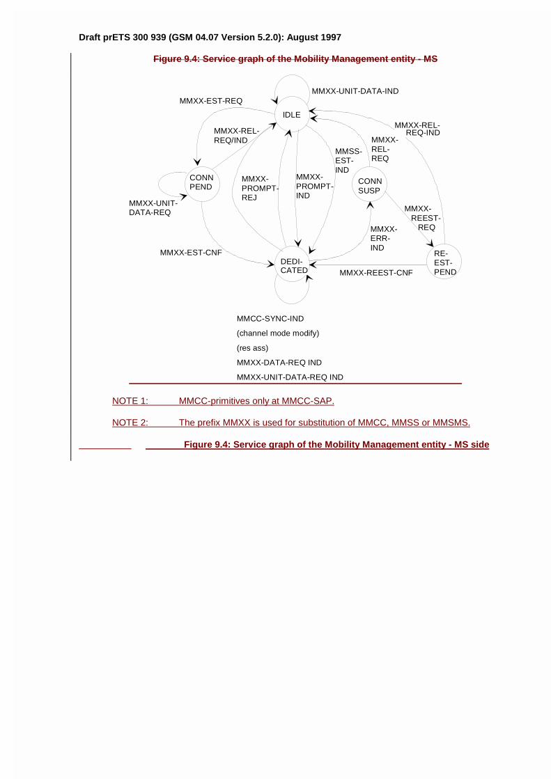
Draft prETS 300 939 (GSM 04.07 Version 5.2.0): August 1997
Figure 9.4: Service graph of the Mobility Management entity - MS
IDLE
DEDI-CATED
MMXX-UNIT-DATA-IND
MMXX-REL- REQ-IND
MMXX-REEST-CNF
MMXX-REL-REQ/IND
MMXX-EST-REQ
MMXX-EST-CNF
MMCC-SYNC-IND
(channel mode modify)
(res ass)
MMXX-DATA-REQ IND
MMXX-UNIT-DATA-REQ IND
RE-EST-PEND
CONNSUSP
CONNPEND
MMXX-UNIT-DATA-REQ
MMXX-REL-REQ
MMXX- REEST- REQMMXX-
ERR-IND
MMSS-EST-IND
MMXX-PROMPT-IND
MMXX-PROMPT-REJ
NOTE 1: MMCC-primitives only at MMCC-SAP.
NOTE 2: The prefix MMXX is used for substitution of MMCC, MMSS or MMSMS.
Figure 9.4: Service graph of the Mobility Management entity - MS side
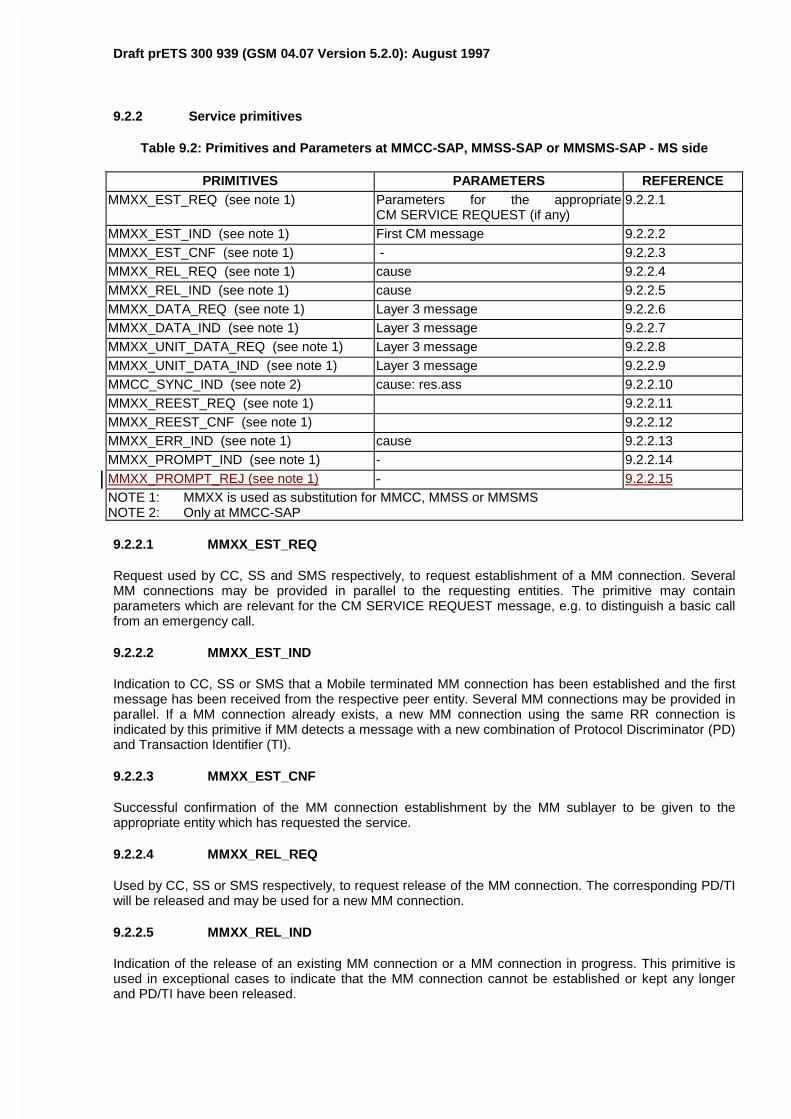
Draft prETS 300 939 (GSM 04.07 Version 5.2.0): August 1997
9.2.2 Service primitives
Table 9.2: Primitives and Parameters at MMCC-SAP, MMSS-SAP or MMSMS-SAP - MS side
PRIMITIVES PARAMETERS REFERENCEMMXX_EST_REQ (see note 1) Parameters for the appropriate
CM SERVICE REQUEST (if any)9.2.2.1
MMXX_EST_IND (see note 1) First CM message 9.2.2.2MMXX_EST_CNF (see note 1) - 9.2.2.3MMXX_REL_REQ (see note 1) cause 9.2.2.4MMXX_REL_IND (see note 1) cause 9.2.2.5MMXX_DATA_REQ (see note 1) Layer 3 message 9.2.2.6MMXX_DATA_IND (see note 1) Layer 3 message 9.2.2.7MMXX_UNIT_DATA_REQ (see note 1) Layer 3 message 9.2.2.8MMXX_UNIT_DATA_IND (see note 1) Layer 3 message 9.2.2.9MMCC_SYNC_IND (see note 2) cause: res.ass 9.2.2.10MMXX_REEST_REQ (see note 1) 9.2.2.11MMXX_REEST_CNF (see note 1) 9.2.2.12MMXX_ERR_IND (see note 1) cause 9.2.2.13MMXX_PROMPT_IND (see note 1) - 9.2.2.14MMXX_PROMPT_REJ (see note 1) - 9.2.2.15NOTE 1: MMXX is used as substitution for MMCC, MMSS or MMSMSNOTE 2: Only at MMCC-SAP
9.2.2.1 MMXX_EST_REQ
Request used by CC, SS and SMS respectively, to request establishment of a MM connection. SeveralMM connections may be provided in parallel to the requesting entities. The primitive may containparameters which are relevant for the CM SERVICE REQUEST message, e.g. to distinguish a basic callfrom an emergency call.
9.2.2.2 MMXX_EST_IND
Indication to CC, SS or SMS that a Mobile terminated MM connection has been established and the firstmessage has been received from the respective peer entity. Several MM connections may be provided inparallel. If a MM connection already exists, a new MM connection using the same RR connection isindicated by this primitive if MM detects a message with a new combination of Protocol Discriminator (PD)and Transaction Identifier (TI).
9.2.2.3 MMXX_EST_CNF
Successful confirmation of the MM connection establishment by the MM sublayer to be given to theappropriate entity which has requested the service.
9.2.2.4 MMXX_REL_REQ
Used by CC, SS or SMS respectively, to request release of the MM connection. The corresponding PD/TIwill be released and may be used for a new MM connection.
9.2.2.5 MMXX_REL_IND
Indication of the release of an existing MM connection or a MM connection in progress. This primitive isused in exceptional cases to indicate that the MM connection cannot be established or kept any longerand PD/TI have been released.
Draft prETS 300 939 (GSM 04.07 Version 5.2.0): August 1997
9.2.2.6 MMXX_DATA_REQ
Request used by the CC, SS or SMS entities for acknowledged control-data transmission.
9.2.2.7 MMXX_DATA_IND
Indication used by MM to transfer the received acknowledged control-data to the CC, SS or SMS entities.
9.2.2.8 MMXX_UNIT_DATA_REQ
Request used by the CC, SS or SMS entities for unacknowledged control-data transmission.
9.2.2.9 MMXX_UNIT_DATA_IND
Indication used by MM to transfer the received unacknowledged control-data to the CC, SS or SMSentities.
9.2.2.10 MMCC_SYNC_IND
Indication that a dedicated channel assignment has been performed and/or the channel mode has beenchanged (only towards the CC entity).
9.2.2.11 MMXX_REEST_REQ
Request to establish a MM connection which has been interrupted by a lower layer failure. The interruptionmust have been indicated by MMXX_ERR_IND.
9.2.2.12 MMXX_REEST_CNF
Confirmation of the successful re-establishment of the MM connection. The MM connection will continuewith PD/TI as it had before.
9.2.2.13 MMXX_ERR_IND
Indication of a lower layer failure interrupting the MM connection. The PD/TI are still kept by MM. In caseof parallel transactions this indication is passed to all CM entities for which a MM connection has beenestablished. It is left to the decision of the appropriate CM entity to either request the re-establishment ofthe MM connection by MMXX_REEST_REQ or to release it by MMXX_REL_REQ.
9.2.2.14 MMXX_PROMPT_IND
Indication given by MM to inform of the completion of the MM connection to the CC, SS or SMS entities fora mobile station which supports “Network Initiated MO CM Connection Request”.
9.2.2.15 MMXX_PROMPT_REJ
Response to the MMXX_PROMPT_IND indication to the MM entity in a mobile station which supports“Network Initiated MO CM Connection Request” in case when the CC entity is unable to establish a newtransaction. After the MM entity has been received the indication the MM connection is released andSTATUS message is sent to the network.
ETSI STC SMG3 WPA Tdoc SMG3 98A023
Sophia Antipolis, FRANCE
03 - 06 February 1998
CHANGE REQUEST No. 04.08-A269
Technical Specification GSM 04.08 version 5.7.0.
Submitted to SMG for approval without presentation ("non-strategic") [ X ]
with presentation ("strategic")[ ]
Status at SMG#25 [ ]: Approved [ ] Rejected [ ] Postponed [ ]
Phase 1: [ ] Phase 2: [ ] Phase 2+: [x] Work item: CCBS
Other phase(s) affected: [ ] If yes, linked CR(s):
Proposed change affects: SIM [ ] ME [ X ] Network [ X ]
Source: SMG3 Date: 03 - 06 February 1998
Subject: New call state values
Category: F - Correction [ ]A - Corresponds to a Phase 2 correction [ ]B - Addition of Feature [ x ]C - Functional modification of Feature[ ]D - Editorial modification [ ]
Reason for change:
Call state values of CC prompt present (U0.2), Wait for network information (U0.3), CC-Establishmentpresent (U0.4), CC-Establisment confirmed (U0.5) and Recall present (U0.6) should be added in table10.80/GSM 04.08.
Sections affected, and additional explanation of details of change (if needed):
See appended pages.
If other core Specifications are affected, necessary (and attached) Joint CRs:
Affects (possibly): MS Test Specifications [ ] BSS Test Specifications [ ] O&M Specifications [ ]Attached CRs?:
Cross Phase Compatibility:Change affects operation of: Phase 1 MS in Phase 2(+) NW [ ] Phase 2(+) MS in Phase 1 NW [ ]
Change affects operation of: Phase 1 SIM in Phase 2(+) ME[ ] Phase 2(+) SIM in Phase 1 ME [ ]
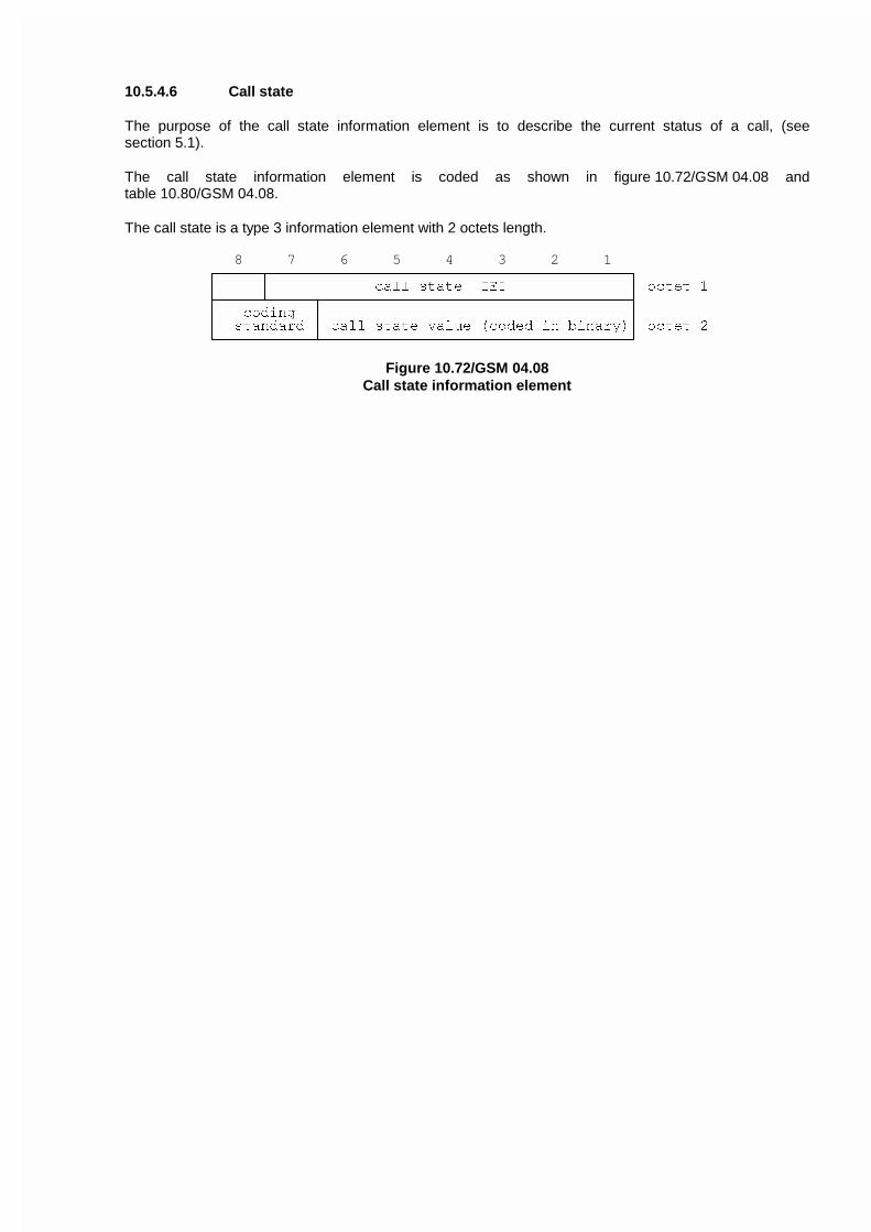
10.5.4.6 Call state
The purpose of the call state information element is to describe the current status of a call, (seesection 5.1).
The call state information element is coded as shown in figure 10.72/GSM 04.08 andtable 10.80/GSM 04.08.
The call state is a type 3 information element with 2 octets length.
8 7 6 5 4 3 2 1HFFFFFNFFFFFFFFFFFFFFFFFFFFFFFFFFFFFFFFFFFFFFFFFI
G G FDOO VWDWH ,(, G RFWHW �
LFFFFFOFFFFFNFFFFFFFFFFFFFFFFFFFFFFFFFFFFFFFFFFFM
G FRGLQJ G G
G VWDQGDUG G FDOO VWDWH YDOXH �FRGHG LQ ELQDU\�G RFWHW �
JFFFFFFFFFFFOFFFFFFFFFFFFFFFFFFFFFFFFFFFFFFFFFFFK
Figure 10.72/GSM 04.08Call state information element
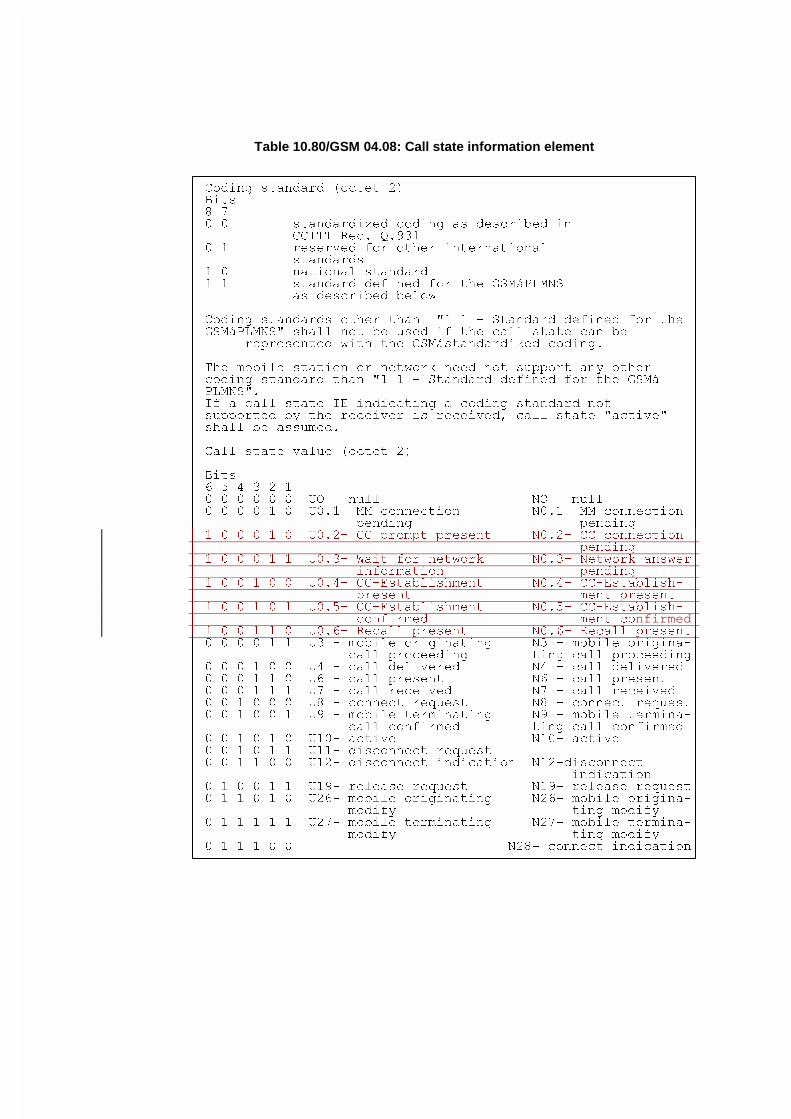
Table 10.80/GSM 04.08: Call state information element
HFFFFFFFFFFFFFFFFFFFFFFFFFFFFFFFFFFFFFFFFFFFFFFFFFFFFFFFFFFFFFFI
G &RGLQJ VWDQGDUG �RFWHW �� G
G %LWV G
G � � G
G � � VWDQGDUGL]HG FRGLQJ DV GHVFULEHG LQ G
G &&,77 5HF� 4���� G
G � � UHVHUYHG IRU RWKHU LQWHUQDWLRQDO G
G VWDQGDUGV G
G � � QDWLRQDO VWDQGDUG G
G � � VWDQGDUG GHILQHG IRU WKH *60i3/016 G
G DV GHVFULEHG EHORZ G
G G
G &RGLQJ VWDQGDUGV RWKHU WKDQ �� � � 6WDQGDUG GHILQHG IRU WKH G
G *60i3/016� VKDOO QRW EH XVHG LI WKH FDOO VWDWH FDQ EH G
G UHSUHVHQWHG ZLWK WKH *60iVWDQGDUGL]HG FRGLQJ� G
G G
G 7KH PRELOH VWDWLRQ RU QHWZRUN QHHG QRW VXSSRUW DQ\ RWKHU G
G FRGLQJ VWDQGDUG WKDQ �� � � 6WDQGDUG GHILQHG IRU WKH *60i G
G 3/016�� G
G ,I D FDOO VWDWH ,( LQGLFDWLQJ D FRGLQJ VWDQGDUG QRW G
G VXSSRUWHG E\ WKH UHFHLYHU LV UHFHLYHG� FDOO VWDWH �DFWLYH� G
G VKDOO EH DVVXPHG� G
G G
G &DOO VWDWH YDOXH �RFWHW �� G
G G
G %LWV G
G � � � � � � G
G � � � � � � 82 � QXOO 12 � QXOO G
G � � � � � � 8���� 00 FRQQHFWLRQ 1���� 00 FRQQHFWLRQ G
G SHQGLQJ SHQGLQJ G
G � � � � � � 8���� && SURPSW SUHVHQW 1���� && FRQQHFWLRQ G
G SHQGLQJ G
G � � � � � � 8���� :DLW IRU QHWZRUN 1���� 1HWZRUN DQVZHUG
G LQIRUPDWLRQ SHQGLQJ G
G � � � � � � 8���� &&�(VWDEOLVKPHQW 1���� &&�(VWDEOLVK� G
G SUHVHQW PHQW SUHVHQW G
G � � � � � � 8���� &&�(VWDEOLVKPHQW 1���� &&�(VWDEOLVK� G
G FRQILUPHG PHQW FRnfirmedGG � � � � � � 8���� 5HFDOO SUHVHQW 1���� 5HFDOO SUHVHQWG
G � � � � � � 8� � PRELOH RULJLQDWLQJ 1� � PRELOH RULJLQD�G
G FDOO SURFHHGLQJ WLQJ FDOO SURFHHGLQJG
G � � � � � � 8� � FDOO GHOLYHUHG 1� � FDOO GHOLYHUHG G
G � � � � � � 8� � FDOO SUHVHQW 1� � FDOO SUHVHQW G
G � � � � � � 8� � FDOO UHFHLYHG 1� � FDOO UHFHLYHG G
G � � � � � � 8� � FRQQHFW UHTXHVW 1� � FRQQHFW UHTXHVWG
G � � � � � � 8� � PRELOH WHUPLQDWLQJ 1� � PRELOH WHUPLQD�G
G FDOO FRQILUPHG WLQJ FDOO FRQILUPHG G
G � � � � � � 8��� DFWLYH 1��� DFWLYH G
G � � � � � � 8��� GLVFRQQHFW UHTXHVW G
G � � � � � � 8��� GLVFRQQHFW LQGLFDWLRQ 1���GLVFRQQHFW G
G LQGLFDWLRQ G
G � � � � � � 8��� UHOHDVH UHTXHVW 1��� UHOHDVH UHTXHVWG
G � � � � � � 8��� PRELOH RULJLQDWLQJ 1��� PRELOH RULJLQD�G
G PRGLI\ WLQJ PRGLI\ G
G � � � � � � 8��� PRELOH WHUPLQDWLQJ 1��� PRELOH WHUPLQD�G
G PRGLI\ WLQJ PRGLI\ G
G � � � � � � 1��� FRQQHFW LQGLFDWLRQG
JFFFFFFFFFFFFFFFFFFFFFFFFFFFFFFFFFFFFFFFFFFFFFFFFFFFFFFFFFFFFFFK
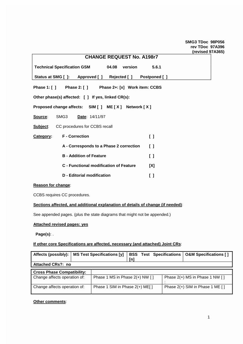
1
SMG3 TDoc 98P056rev TDoc 97A396(revised 97A365)
CHANGE REQUEST No. A198r7
Technical Specification GSM 04.08 version 5.6.1
Status at SMG [ ]: Approved [ ] Rejected [ ] Postponed [ ]
Phase 1: [ ] Phase 2: [ ] Phase 2+: [x] Work item: CCBS
Other phase(s) affected: [ ] If yes, linked CR(s):
Proposed change affects: SIM [ ] ME [ X ] Network [ X ]
Source: SMG3 Date: 14/11/97
Subject: CC procedures for CCBS recall
Category: F - Correction [ ]
A - Corresponds to a Phase 2 correction [ ]
B - Addition of Feature [ ]
C - Functional modification of Feature [X]
D - Editorial modification [ ]
Reason for change:
CCBS requires CC procedures.
Sections affected, and additional explanation of details of change (if needed):
See appended pages. (plus the state diagrams that might not be appended.)
Attached revised pages: yes
Page(s): .
If other core Specifications are affected, necessary (and attached) Joint CRs:
Affects (possibly): MS Test Specifications [y] BSS Test Specifications[n]
O&M Specifications [ ]
Attached CRs?: no
Cross Phase Compatibility:Change affects operation of: Phase 1 MS in Phase 2(+) NW [ ] Phase 2(+) MS in Phase 1 NW [ ]
:Change affects operation of: Phase 1 SIM in Phase 2(+) ME[ ] Phase 2(+) SIM in Phase 1 ME [ ]
Other comments:
Page -GSM 04.08 Version 5.6.1 August 1997
2
2
5 Elementary procedures for circuit-switched Call Control
5.1 Overview
5.1.1 General
This section describes the call control (CC) protocol, which is one of the protocols of theConnection Management (CM) sublayer (see GSM 04.07).
Every mobile station must support the call control protocol. If a mobile station does not supportany bearer capability at all then it shall respond to a SETUP message with a RELEASECOMPLETE message as specified in section 5.2.2.2.
In the call control protocol, more than one CC entity are defined. Each CC entity is independentfrom each other and shall communicate with the correspondent peer entity using its own MMconnection. Different CC entities use different transaction identifiers.
With a few exceptions this Technical Specification describes the call control protocol only withregard to two peer entities. The call control entities are described as communicating finite statemachines which exchange messages across the radio interface and communicate internally withother protocol (sub)layers. This description isin only normative as far as the consequentialexternally observable behaviour is concerned.
Certain sequences of actions of the two peer entities compose "elementary procedures" which areused as a basis for the description in this section. These elementary procedures may be groupedinto the following classes:
- call establishment procedures;- call clearing procedures;- call information phase procedures;- miscellaneous procedures.
The terms "mobile originating" or "mobile originated" (MO) are used to describe a call initiated bythe mobile station. The terms "mobile terminating" or "mobile terminated" (MT) are used todescribe a call initiated by the network.
Figure 5.1a/GSM 04.08 gives an overview of the main states and transitions on the mobile stationside.
Figure 5.1b/GSM 04.08 gives an overview of the main states and transitions on the network side.
{ CR Editor’ Note :
The extensions to figures 5.1a and 5.1b shown should be merged with the main figures. Theeditor(s) were unable to do this because of the lack of the correct editing tool.
The MS side extension figure shows how for the Network Initated MO call the MS reaches stateU1.0 from state U0.
The Network side extension figure shows for Network Initiated MO Calls the Network reachesstate N1.0 from state N0. }
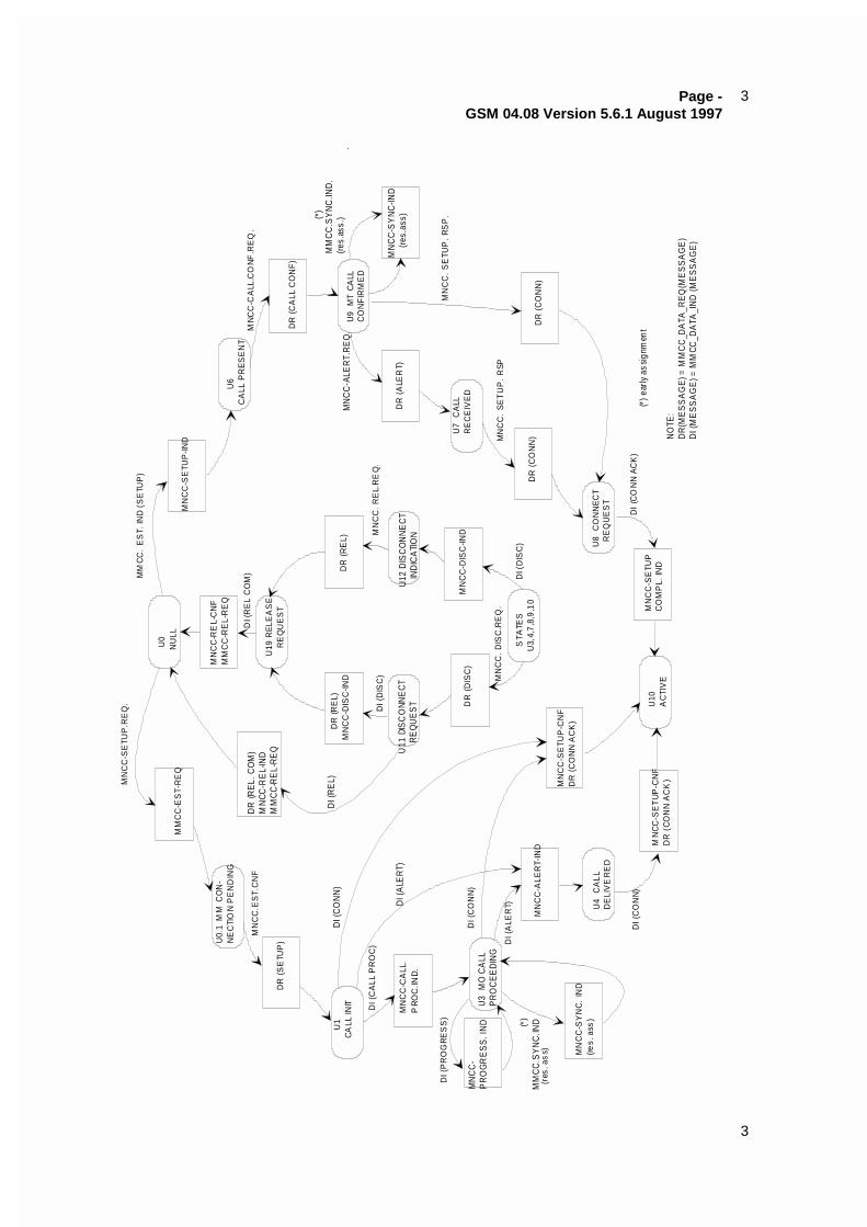
Page -GSM 04.08 Version 5.6.1 August 1997
3
3
MN
CC
-RE
L-C
NF
MM
CC
-RE
L-R
EQ
U19
RE
LEA
SE
R
EQ
UE
ST
DR
(R
EL)
DR
(RE
L)M
NC
C-D
ISC
-IND
U11
DIS
CO
NNE
CT
R
EQ
UE
ST
U12
DIS
CO
NN
EC
T
IND
ICA
TIO
N
MN
CC
-SE
TUP
-IND
U6
CA
LL P
RE
SE
NT
DR
(C
ALL
CO
NF
)
U9
MT
CA
LLC
ON
FIR
ME
D
DR
(ALE
RT)
MN
CC
-SY
NC
-IND
(r
es.a
ss)
U7
CA
LLR
EC
EIV
ED
DR
(C
ON
N)
DR
(C
ON
N)
MN
CC
-DIS
C-IN
D
U8
CO
NN
EC
T
RE
QU
ES
T
MN
CC
-SE
TUP
CO
MP
L. IN
D
DR
(D
ISC
)
STA
TES
U3,
4,7
,8,9
,10
MM
CC
-ES
T-R
EQ
DR
(RE
L. C
OM
)M
NCC
-RE
L-IN
DM
MC
C-R
EL-
RE
QD
R (
SE
TUP
)
U
1C
ALL
INIT
MN
CC
-CA
LL.
PR
OC
.IND
.
MN
CC
-P
RO
GR
ES
S. I
ND
U3
MO
CA
LLP
RO
CE
ED
ING
MN
CC
-SY
NC
. IN
D(re
s. a
ss)
MN
CC
-ALE
RT-
IND
U4
CA
LL
DE
LIV
ER
ED
MN
CC
-SE
TUP
-CN
FD
R (
CO
NN
AC
K)
MN
CC
-SE
TU
P-C
NF
DR
(C
ON
N A
CK
)
U10
AC
TIV
E
MN
CC
-SE
TUP
.RE
Q.
MM
CC
. E
ST.
IND
(S
ETU
P)
MN
CC
-CA
LL.C
ON
F.R
EQ
.
MN
CC
-ALE
RT.
RE
Q.
(*)
MM
CC
.SY
NC
.IND
.(re
s.as
s.)
MN
CC
. S
ETU
P.
RS
P.
MN
CC
. S
ET
UP
. R
SP
DI
(CO
NN
AC
K)
DI (
DIS
C)
MN
CC
. R
EL.
RE
Q.
MN
CC
. D
ISC
.RE
Q.
DI (
DIS
C)
DI (
RE
L C
OM
)
DI (
CA
LL P
RO
C)
DI (
PR
OG
RE
SS
)
DI (
CO
NN
)
DI (
ALE
RT)
DI (
CO
NN
)
MM
CC
.SY
NC
.IND(*)
(res
. as
s)
(*) e
arly
ass
ignm
ent
U0
NU
LL
U0.
1 M
M C
ON
-N
EC
TIO
N P
EN
DIN
G
DI (
CO
NN
)
DI (
ALE
RT)
MN
CC
.ES
T.C
NF
NO
TE:
DR
(ME
SS
AG
E) =
MM
CC
_DA
TA_R
EQ
(ME
SS
AG
E)
DI (
ME
SS
AG
E) =
MM
CC_D
ATA
_IN
D (M
ES
SA
GE
)
DI (
RE
L)
.
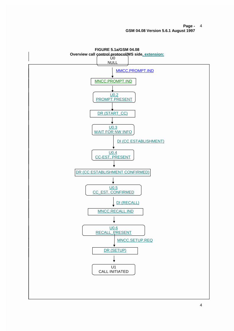
Page -GSM 04.08 Version 5.6.1 August 1997
4
4
FIGURE 5.1a/GSM 04.08Overview call control protocol/MS side, extension:
MNCC.PROMPT.IND
U0NULL
U0.2PROMPT PRESENT
MMCC.PROMPT.IND
U0.3WAIT FOR NW INFO
U0.4CC-EST. PRESENT
DR (START_CC)
DR (CC ESTABLISHMENT CONFIRMED)
MNCC.RECALL.IND
U1CALL INITIATED
DR (SETUP)
DI (RECALL)
DI (CC ESTABLISHMENT)
MNCC.SETUP.REQ
U0.5CC_EST. CONFIRMED
U0.6RECALL_PRESENT
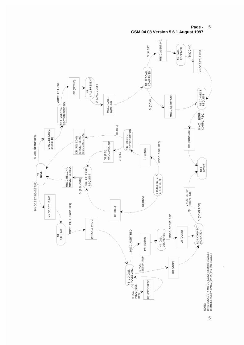
Page -GSM 04.08 Version 5.6.1 August 1997
5
5
N
0N
ULL
MN
CC
.SE
TUP
.IND
.M
MC
C.E
ST.
REQ
.(m
obile
ID)
MN
CC
.RE
L.C
NF.
MM
CC
.RE
L.R
EQ
.
N0.
1 M
M-C
ON
-N
EC
TIO
N P
EN
DIN
G
DR
(S
ETU
P)
N6
CA
LL P
RE
SE
NT
MN
CC
.CA
LL.
CO
NF.IN
D
N9
MT
CA
LL C
ON
FIR
MED
MN
CC
.ALE
RT.
IND
.
MN
CC
.SE
TUP
.CN
F.
N7
CA
LLR
EC
EIV
ED
MN
CC
.SE
TUP
.CN
FN
8 C
ON
NE
CT
RE
QU
ES
T
DR
(C
ON
N A
CK
)
N19
RE
LEA
SE
RE
QU
ES
T
DR
(RE
L C
OM
),M
NC
C.R
EL.
IND
,M
MC
C.R
EL.
RE
Q.
DR
(R
EL)
MN
CC
.DIS
C.IN
D
N12
D
ISC
ON
-N
EC
T IN
DIC
ATIO
N
DR
(DIS
C)
N1
CA
LL IN
IT
N3
MO
CA
LLP
RO
CE
ED
ING
DR
(P
RO
GR
ES
S)
DR
(A
LER
T)
DR
(CO
NN)
N4
CA
LLD
ELI
VE
RE
D
DR
(CO
NN
)
N28
CO
NN
EC
TIN
DIC
ATI
ON
MN
CC
. S
ETU
P.
CO
MP
L. IN
D.
N1
0A
CTI
VE
DR
(C
ALL
PR
OC
)
MM
CC
.ES
T.IN
D (S
ETU
P)
MN
CC
. S
ETU
P R
EQ
.
MM
CC
. ES
T. C
NF
.
DI (
CA
LL C
ON
F)
DI (
ALE
RT)
DI (
CO
NN
)_
DI (
CO
NN
)
MN
CC.
SE
TUP
.C
OM
PL.
RE
Q.
DI (
CO
NN
AC
K)
MN
CC
. S
ETU
P.
RS
P
MN
CC
. D
ISC
. R
EQ
.
DI (
DIS
C)
DI (
DIS
C)
DI (
RE
L)
DI (
RE
L C
OM
)
MN
CC
. CA
LL. P
RO
C. R
EQ
MN
CC
. P
RO
GR
ES
S.
RE
Q.
MN
CC
. S
ETU
P.
RS
P
DR
(R
EL)
STA
TES
N1,
3,
4,7,
8,
9; 1
0, 2
8
MN
CC
ALE
RT
RE
Q
NO
TE:
DR
(ME
SS
AG
E) =
MM
CC
_DA
TA_R
EQ
(ME
SS
AG
E)
DI (
ME
SS
AG
E) =
MM
CC
_DA
TA_I
ND
(ME
SS
AG
E)
.
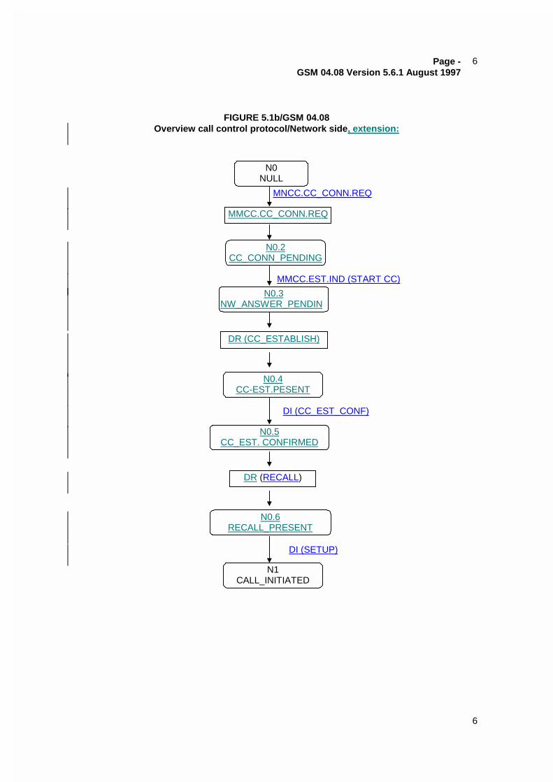
Page -GSM 04.08 Version 5.6.1 August 1997
6
6
FIGURE 5.1b/GSM 04.08Overview call control protocol/Network side, extension:
MNCC.CC_CONN.REQ
MMCC.CC_CONN.REQ
N0NULL
N0.2CC_CONN_PENDING
N0.3NW_ANSWER_PENDIN
DR (CC_ESTABLISH)
N0.4CC-EST.PESENT
N0.5CC_EST. CONFIRMED
DR (RECALL)
N0.6RECALL_PRESENT
N1CALL_INITIATED
MMCC.EST.IND (START CC)
DI (CC_EST_CONF)
DI (SETUP)
Page -GSM 04.08 Version 5.6.1 August 1997
7
7
5.1.2 Call Control States
5.1.2.1 Call states at the mobile station side of the interface
The states which may exist on the mobile station side of the radio interface are defined in thissection.
NOTE: States U0.1, U0.2, U0.3, U0.4, U0.5, U0.6, U26, and U27 are GSM specific. Allother states are CCITTITU-T defined.
5.1.2.1.1 Null (State U0)
No call exists.
5.1.2.1.2 MM Connection pending (U0.1)
This state exists for a mobile originating call, when the mobile station requests the establishmentof a MM connection.
5.1.2.1.2a CC prompt present (U0.2)
This state exists for a mobile originating call when the network has prompted the mobile station toestablish a CC connection but the mobile station has not yet responded.
Note: This state is transient.
5.1.2.1.2b Wait for network information (U0.3)
This state exists for a mobile originating call when the mobile station has responded to the promptfrom the network to establish a CC connection and the mobile station is waiting for furtherinformation from the network.
5.1.2.1.2c CC-Establishment present (U0.4)
This state exists for a mobile originating call when the mobile station has received a CC-establishment request but has not yet responded.
Note: This state is transient.
5.1.2.1.2d CC-Establishment confirmed (U0.5)
This state exists for a mobile originating call when the mobile station has sent theacknowledgement that the mobile station has received all the CC information that is needed.
5.1.2.1.2e Recall present (U0.6)
This state exists for a mobile originating call when the mobile station has received a recall requestbut has not yet responded.
Note: This state is transient.
Page -GSM 04.08 Version 5.6.1 August 1997
8
8
5.1.2.1.3 Call initiated (U1)
This state exists for a mobile originating call, when the MS requests call establishment from thenetwork.
5.1.2.1.4 Mobile originating call proceeding (U3)
This state exists for a mobile originating call when the mobile station has receivedacknowledgement that the network has received all call information necessary to effect callestablishment.
5.1.2.1.5 Call delivered (U4)
This state exists for a mobile originating call, when the calling mobile station has received anindication that remote user alerting has been initiated.
5.1.2.1.6 Call present (U6)
This state exists for a mobile terminating call when the mobile station has received a callestablishment request but has not yet responded.
5.1.2.1.7 Call received (U7)
This state exists for a mobile terminating call when the mobile station has indicated alerting buthas not yet answered.
5.1.2.1.8 Connect Request (U8)
This state exists for a mobile terminating call, when the mobile station has answered the call andis waiting to be awarded the call.
5.1.2.1.9 Mobile terminating call confirmed (U9)
This state exists for a mobile terminating call when the mobile station has sent acknowledgementthat the mobile station has received all call information necessary to effect call establishment.
5.1.2.1.10 Active (U10)
This state exists for a mobile terminating call when the MS has answered the call. This stateexists for a mobile originating call when the MS has received an indication that the remote userhas answered the call.
5.1.2.1.11 Disconnect request (U11)
This state exists when the mobile station has requested the network to clear the end-to-endconnection (if any) and is waiting for a response.
5.1.2.1.12 Disconnect indication (U12)
This state exists when the mobile station has received an invitation to disconnect because thenetwork has disconnected the end-to-end connection (if any).
Page -GSM 04.08 Version 5.6.1 August 1997
9
9
5.1.2.1.13 Release request (U19)
This state exists when the MS has requested the network to release and is waiting for a response.
5.1.2.1.14 Mobile originating modify (U26)
This state exists when the mobile station has sent a request to the network for a new mode buthas not yet received an answer.
5.1.2.1.15 Mobile terminating modify (U27)
This state exists when the mobile station has received a request from the network for a new modeand has not yet sent a response to this request.
5.1.2.2 Network call states
NOTE: States N0.1, N0.2, N0.3, N0.4, N0.5, N0.6 N26, N27, N28, N3a, N4,a, N7a,and N9a are GSM specific. All other states are CCITT defined.
The call states that may exist on the network side of the radio interface are defined in this section.
5.1.2.2.1 Null (State N0)
No call exists.
5.1.2.2.2 MM connection pending (N0.1)
This state exists for a mobile terminating call, when the network requests the establishment of aMM connection.
5.1.2.2.2a CC connection pending (N0.2)
This state exists for a mobile originating call when the network has requested the mobile station toestablish a CC connection.
5.1.2.2.2b Network answer pending (N0.3)
This state exists for a mobile originating call when the mobile station has established a CCconnection upon the request of the network, but the network has not yet informed the mobilestation of the reason for the network’s action.
5.1.2.2.2c CC-Establishment present (N0.4)
This state exists for a mobile originating call when the network has sent a CCrecall establishmentrequest but has not yet received a satisfactory response.
5.1.2.2.2d CC-Establishment confirmed (N0.5)
This state exists for a mobile originating call when the network has received acknowledgementthat the mobile station has received all call information necessary to effect call establishment.
Page -GSM 04.08 Version 5.6.1 August 1997
10
10
5.1.2.2.2e Recall present (N0.6)
This state exists for a mobile originating call when the network has sent a recall request but hasnot yet received a satisfactory response.
5.1.2.2.3 Call initiated (N1)
This state exists for a mobile originating call when the network has received a call establishmentrequest but has not yet responded.
5.1.2.2.4 Mobile originating call proceeding (N3)
This state exists for a mobile originating call when the network has sent acknowledgement thatthe network has received all call information necessary to effect call establishment.
5.1.2.2.5 Call delivered (N4)
This state exists for a mobile originating call when the network has indicated that remote useralerting has been initiated.
5.1.2.2.6 Call present (N6)
This state exists for a mobile terminating call when the network has sent a call establishmentrequest but has not yet received a satisfactory response.
5.1.2.2.7 Call received (N7)
This state exists for a mobile terminating call when the network has received an indication that themobile station is alerting but has not yet received an answer.
5.1.2.2.8 Connect request (N8)
This state exists for a mobile terminating call when the network has received an answer but thenetwork has not yet awarded the call.
5.1.2.2.9 Mobile terminating call confirmed (N9)
This state exists for a mobile terminating call when the network has received acknowledgementthat the mobile station has received all call information necessary to effect call establishment.
5.1.2.2.10 Active (N10)
This state exists for a mobile terminating call when the network has awarded the call to the calledmobile station. This state exists for a mobile originating call when the network has indicated thatthe remote user has answered the call.
Page -GSM 04.08 Version 5.6.1 August 1997
11
11
5.1.2.2.11 {Not used}
5.1.2.2.12 Disconnect indication (N12)
This state exists when the network has disconnected the end- to-end connection (if any) and hassent an invitation to disconnect the mobile station to network connection.
5.1.2.2.13 Release request (N19)
This state exists when the network has requested the MS to release and is waiting for a response.
5.1.2.2.14 Mobile originating modify (N26)
This state exists when the network has received a request from the mobile station for a new modebut has not yet sent a response.
5.1.2.2.15 Mobile terminating modify (N27)
This state exists when the network has sent a request to the mobile station for a new mode buthas not yet received an answer.
5.1.2.2.16 Connect Indication (N28)
This state exists for a mobile originating call when the network has indicated that the remote userhas answered the call and the network is waiting for acknowledgement by the mobile station.
5.2 Call establishment procedures
Establishment of a call is initiated by request of upper layer in either the mobile station or thenetwork; it consists of:
- the establishment of a CC connection between the mobile station and the network;- the activation of the codec or interworking function.
Whenever it is specified in GSM 04.08, section 5 that the mobile station shall attach the userconnection, this means that the mobile station shall activate the codec or interworking function assoon as an appropriate channel is available. The mobile station shall de-activate the codec orinterworking function whenever an appropriate channel is no longer available. As soon as anappropriate channel is (again) available, the codec or interworking function shall be re-activated. Ifa new order to attach the user connection is received, the new order shall supersede the previousone.
A channel shall be considered as appropriate if it is consistent with the possibly negotiated bearercapability applicable for the actual phase of the call. The mobile station shall not consider achannel as not appropriate because the type of the channel (full rate/half rate) is not the preferredone. If:
- the user connection has to be attached but no appropriate channel is available for acontiguous time of 30 seconds; or if
- the codec or interworking function is de-activated for a contiguous time of 30 seconds;
then the mobile station may initiate call clearing.
Page -GSM 04.08 Version 5.6.1 August 1997
12
12
Upon request of upper layers to establish a call, restricting conditions for the establishment of thecall are examined. These restricting conditions concern the states of parallel CC entities and aredefined elsewhere. If these restricting conditions are fulfilled, the call establishment is rejected.Otherwise a CC entity in state U0, "null", is selected to establish the call. It initiates theestablishment by requesting the MM sublayer to establish an MM connection.
5.2.1 Mobile originating call establishment
The call control entity of the mobile station initiates establishment of a CC connection byrequesting the MM sublayer to establish a mobile originating MM connection and entering the "MMconnection pending" state. There are two kinds of a mobile originating call: basic call andemergency call. The request to establish an MM connection shall contain a parameter to specifywhether the call is a basic or an emergency call. This information may lead to specific qualities ofservices to be provided by the MM sublayers. Timer T303 is started when the CM SERVICEREQUEST message is sent.
For mobile stations supporting eMLPP basic calls may optionally have an associated priority levelas defined in GSM 03.67. This information may also lead to specified qualities of service to beprovided by the MM sublayers.
While being in the "MM connection pending" state, the call entity of the mobile station may cancelthe call prior to sending the first call control message according to the rules given in section4.5.1.7.
Having entered the "MM connection pending" state, upon MM connection establishment, the callcontrol entity of the mobile station sends a setup message to its peer entity. This setup messageis
- a SETUP message, if the call to be established is a basic call, and- an EMERGENCY SETUP message, if the call to be established is an emergency call.
It then enters the "call initiated" state. Timer T303 is not stopped.
The setup message shall contain all the information required by the network to process the call. Inparticular, the SETUP message shall contain the called party address information.
If timer T303 elapses in the "MM connection pending" state, the MM connection in progress shallbe aborted and the user shall be informed about the rejection of the call.
5.2.1.1 Call initiation
Having entered the "MM connection pending" state, upon MM connection establishment, the callcontrol entity of the mobile station sends a setup message to its peer entity. This setup messageis:
- a SETUP message, if the call to be established is a basic call, and- an EMERGENCY SETUP message, if the call to be established is an emergency call.
It then enters the "call initiated" state. Theis state “call initiated” state is supervised by timerT303.,For normal MO calls, this timer which haswill have already been started after entering the"MM connection pending" state. For network-initiated MO calls this timer will be started in therecall present state as defined in section 5.2.3.4
Page -GSM 04.08 Version 5.6.1 August 1997
13
13
The setup message shall contain all the information required by the network to process the call. Inparticular, the SETUP message shall contain the called party address information.
When the call control entity of the mobile station is in the "call initiated" state and if it receives:
i) a CALL PROCEEDING message, it shall proceed as described in section 5.2.1.3;
ii) an ALERTING message, it shall proceed as described in section 5.2.1.5;
iii) a CONNECT message, it shall proceed as described in section 5.2.1.6;
iv) a RELEASE COMPLETE message it shall proceed as described in section 5.2.1.2.
Abnormal case:
Since timer T303 is used to supervise the two consecutive states "MM connection pending"and "call initiated", the expiry of timer T303 leads to different actions depending on therespective state:
- If timer T303 elapses in the "MM connection pending" state, the MM connection inprogress shall be aborted and the user shall be informed about the rejection of thecall.
- If timer T303 elapses in the "call initiated" state before any of the CALLPROCEEDING, ALERTING, CONNECT or RELEASE COMPLETE messages hasbeen received, the clearing procedure described in section 5.4 is performed.
5.2.1.2 Receipt of a setup message
In the "null", or “recall present” states, upon receipt of a setup message (a SETUP message oran EMERGENCY SETUP message, see section 5.2.1.1), the call control entity of the networkenters the "call initiated" state. It shall then analyse the call information contained in the setupmessage.
i) If, following the receipt of the setup message, the call control entity of the networkdetermines that the call information received from the mobile station is invalid (e.g. invalidnumber), then the network shall initiate call clearing as defined in section 5.4 with one of thefollowing cause values:
# 1 "unassigned (unallocated) number"# 3 "no route to destination"# 22 "number changed"# 28 "invalid number format (incomplete number)"
ii) If, following the receipt of the setup message, the call control entity of the networkdetermines that a requested service is not authorized or is not available, it shall initiate callclearing in accordance with section 5.4.2 with one of the following cause values:
# 8 "operator determined barring",# 57 "bearer capability not authorized",# 58 "bearer capability not presently available",# 63 "service or option not available, unspecified", or# 65 "bearer service not implemented".
Page -GSM 04.08 Version 5.6.1 August 1997
23
23
MS NetworkHFFFFFFFFFFFFFFFFFFFFFFFFI
G &211(&7 G
G ���������������������! G
G &211(&7 $&.12:/('*( G
G ��������������������� G
JFFFFFFFFFFFFFFFFFFFFFFFFK
Figure 5.7/GSM 04.08Call acceptance and active indication at mobile terminating call establishment
5.2.2.7 Traffic channel assignment at mobile terminating call establishment
It is a network dependent decision when to initiate the assignment of a traffic channel during themobile terminating call establishment phase.
Initiation of the assignment phase does not directly change the state of a CC entity nor affect anycall control timer, but may have suchsome secondary effects (see e.g. clause 5.2.2.3.2).
5.2.2.8 Call queuing at mobile terminating call establishment
The principles described in section 5.2.1.1.10 apply accordingly.
NOTE: The interworking to the fixed network has to fulfil the network specificrequirements.
5.2.2.9 User connection attachment during a mobile terminating call
For speech calls:
The mobile station shall attach the user connection at latest when sending the connectmessage.
For data calls:
The mobile station shall attach the user connection when receiving the CONNECTACKNOWLEDGE message from the network.
5.2.3 Network initiated MO call
The procedures of section 5.2.3 are mandatory for mobile stations supporting “Network initiatedMO call”.
Note: the behaviour of a mobile station that does not support “Network initiated MO call” isdescribed in section 4.
5.2.3.1 Initiation
Before call establishment can be initiated in the mobile station, the MM connection shall beestablished by the network.
After the arrival of an appropriate stimulus (for example a Remote User Free Indication), thecorresponding call control entity in the network shall initiate the MM connection establishmentaccording to section 4, enter the "CC connection pending" state and start timer T331T3Na. Therequest to establish the MM connection is passed from the CM sublayer to the MM sublayer. Itcontains the necessary routing information derived from the received stimulus.
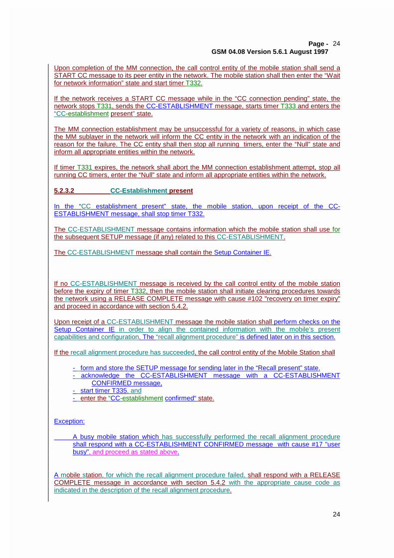
Page -GSM 04.08 Version 5.6.1 August 1997
24
24
Upon completion of the MM connection, the call control entity of the mobile station shall send aSTART CC message to its peer entity in the network. The mobile station shall then enter the “Waitfor network information” state and start timer T332.
If the network receives a START CC message while in the “CC connection pending” state, thenetwork stops T331, sends the CC-ESTABLISHMENT message, starts timer T333 and enters the“CC-establishment present” state.
The MM connection establishment may be unsuccessful for a variety of reasons, in which casethe MM sublayer in the network will inform the CC entity in the network with an indication of thereason for the failure. The CC entity shall then stop all running timers, enter the “Null” state andinform all appropriate entities within the network.
If timer T331 expires, the network shall abort the MM connection establishment attempt, stop allrunning CC timers, enter the “Null” state and inform all appropriate entities within the network.
5.2.3.2 CC-Establishment present
In the “CC establishment present” state, the mobile station, upon receipt of the CC-ESTABLISHMENT message, shall stop timer T332.
The CC-ESTABLISHMENT message contains information which the mobile station shall use forthe subsequent SETUP message (if any) related to this CC-ESTABLISHMENT.
The CC-ESTABLISHMENT message shall contain the Setup Container IE.
If no CC-ESTABLISHMENT message is received by the call control entity of the mobile stationbefore the expiry of timer T332, then the mobile station shall initiate clearing procedures towardsthe network using a RELEASE COMPLETE message with cause #102 "recovery on timer expiry"and proceed in accordance with section 5.4.2.
Upon receipt of a CC-ESTABLISHMENT message the mobile station shall perform checks on theSetup Container IE in order to align the contained information with the mobile’s presentcapabilities and configuration. The “recall alignment procedure” is defined later on in this section.
If the recall alignment procedure has succeeded, the call control entity of the Mobile Station shall
- form and store the SETUP message for sending later in the “Recall present” state,- acknowledge the CC-ESTABLISHMENT message with a CC-ESTABLISHMENT
CONFIRMED message,- start timer T335, and- enter the “CC-establishment confirmed“ state.
Exception:
A busy mobile station which has successfully performed the recall alignment procedureshall respond with a CC-ESTABLISHMENT CONFIRMED message with cause #17 "userbusy", and proceed as stated above.
A mobile station, for which the recall alignment procedure failed, shall respond with a RELEASECOMPLETE message in accordance with section 5.4.2 with the appropriate cause code asindicated in the description of the recall alignment procedure.
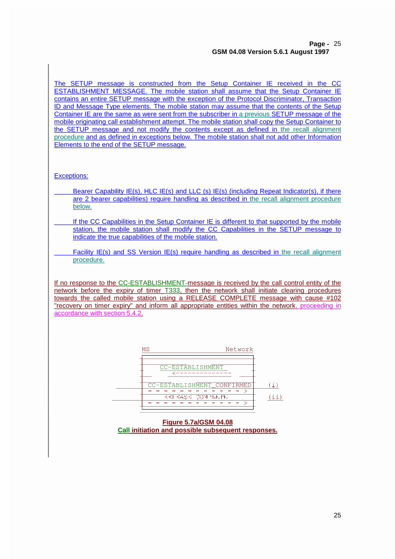
Page -GSM 04.08 Version 5.6.1 August 1997
25
25
The SETUP message is constructed from the Setup Container IE received in the CCESTABLISHMENT MESSAGE. The mobile station shall assume that the Setup Container IEcontains an entire SETUP message with the exception of the Protocol Discriminator, TransactionID and Message Type elements. The mobile station may assume that the contents of the SetupContainer IE are the same as were sent from the subscriber in a previous SETUP message of themobile originating call establishment attempt. The mobile station shall copy the Setup Container tothe SETUP message and not modify the contents except as defined in the recall alignmentprocedure and as defined in exceptions below. The mobile station shall not add other InformationElements to the end of the SETUP message.
Exceptions:
Bearer Capability IE(s), HLC IE(s) and LLC (s) IE(s) (including Repeat Indicator(s), if thereare 2 bearer capabilities) require handling as described in the recall alignment procedurebelow.
If the CC Capabilities in the Setup Container IE is different to that supported by the mobilestation, the mobile station shall modify the CC Capabilities in the SETUP message toindicate the true capabilities of the mobile station.
Facility IE(s) and SS Version IE(s) require handling as described in the recall alignmentprocedure.
If no response to the CC-ESTABLISHMENT message is received by the call control entity of thenetwork before the expiry of timer T333, then the network shall initiate clearing procedurestowards the called mobile station using a RELEASE COMPLETE message with cause #102"recovery on timer expiry" and inform all appropriate entities within the network, proceeding inaccordance with section 5.4.2.
MS NetworkHFFFFFFFFFFFFFFFFFFFFFFFFFFFI
G GG CC-ESTABLISHMENT GG <-------------- GG G
G CC-ESTABLISHMENT_CONFIRMEDG �L�G � � � � � � � � � � � � ! G
G 5(/($6( &203/(7( G (ii)G � � � � � � � � � � � � ! G
JFFFFFFFFFFFFFFFFFFFFFFFFFFFK
Figure 5.7a/GSM 04.08Call initiation and possible subsequent responses.
Page -GSM 04.08 Version 5.6.1 August 1997
26
26
5.2.3.2.1 Recall Alignment Procedure
The recall alignment procedure consists of two parts :
- basic service group alignment, and
- facility alignment.
Basic service group alignment:
The mobile station shall check that the Bearer Capability, HLC and LLC and Repeat Indicatorfields, which are embedded in the Setup Container IE, match a basic service group supported bythe mobile station.
If this check fails, then the recall alignment procedure has failed. The mobile station shall use thecause #88 “incompatible destination” afterwards.
Otherwise, the mobile station is allowed to alter the content within the Bearer Capability, HLC andLLC Information Elements (e.g. the speech coder version(s), the data rate, the radio channelrequirement) provided that the basic service group is not changed. The result shall be that themobile station has derived Bearer Capability, HLC and LLC Information Elements, which it canuse for a later call setup according to its configuration and capabilities.
Facility alignment:
This only applies if the Setup Container contains 1 or more Facility IEs. Each Facility IEwithin the Setup Container will be associated with the common SS Version IE, if present.The handling for each Facility IE is defined below. The mobile station shall align eachfacility IE contained in the Setup Container. The rules defined in GSM 04.10 also apply.The handling of more than one SS Version IE is implementation dependent and not furtherspecified.
The Facility IE is encoded as ‘simple recall alignment’, ‘advanced recall alignment’ or ‘recallalignment not essential’ (see GSM 04.10). If the encoding indicates, that
- a simple recall alignment is required, the mobile station shall copy the Facility IE and thecommon SS version IE from the Setup Container to the SETUP message without modifyingthe content.
- an advanced recall alignment is required, the mobile station must recognise and supportthe operation defined in the facility. If the mobile station does not recognise or support theoperation, then the recall alignment procedure has failed and the mobile station shall usethe cause #29 “facility rejected” in the subsequent rejection of the CC establishmentrequest.
- the recall alignment is not essential, then the facility operation is not an essential part of theSETUP. If the MS does not recognise the operation then the SS Version IE and Facility IEare discarded, and NOT copied into the SETUP message.
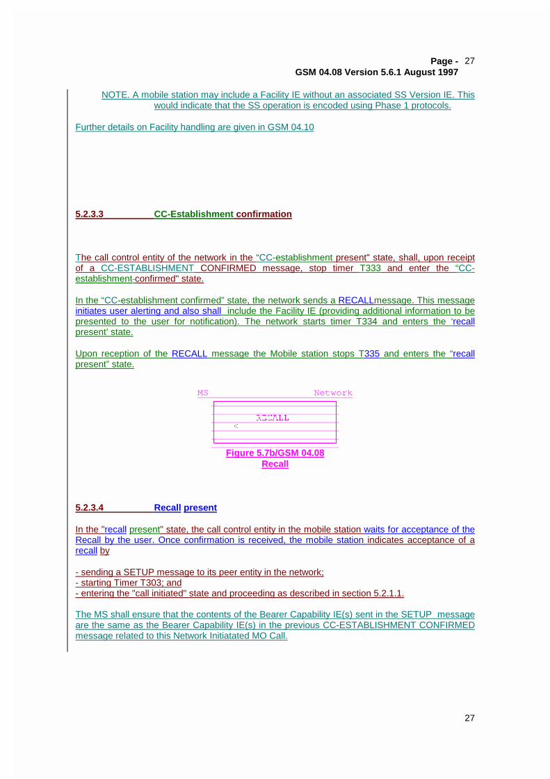
Page -GSM 04.08 Version 5.6.1 August 1997
27
27
NOTE. A mobile station may include a Facility IE without an associated SS Version IE. Thiswould indicate that the SS operation is encoded using Phase 1 protocols.
Further details on Facility handling are given in GSM 04.10
5.2.3.3 CC-Establishment confirmation
The call control entity of the network in the “CC-establishment present" state, shall, upon receiptof a CC-ESTABLISHMENT CONFIRMED message, stop timer T333 and enter the “CC-establishment confirmed" state.
In the “CC-establishment confirmed” state, the network sends a RECALLmessage. This messageinitiates user alerting and also shall include the Facility IE (providing additional information to bepresented to the user for notification). The network starts timer T334 and enters the ‘recallpresent’ state.
Upon reception of the RECALL message the Mobile station stops T335 and enters the “recallpresent” state.
MS NetworkHFFFFFFFFFFFFFFFFFFFFFI
G G
G 5(&$// G
G ��������������� G
G G
JFFFFFFFFFFFFFFFFFFFFFK
Figure 5.7b/GSM 04.08Recall
5.2.3.4 Recall present
In the "recall present" state, the call control entity in the mobile station waits for acceptance of theRecall by the user. Once confirmation is received, the mobile station indicates acceptance of arecall by
- sending a SETUP message to its peer entity in the network;- starting Timer T303; and- entering the "call initiated" state and proceeding as described in section 5.2.1.1.
The MS shall ensure that the contents of the Bearer Capability IE(s) sent in the SETUP messageare the same as the Bearer Capability IE(s) in the previous CC-ESTABLISHMENT CONFIRMEDmessage related to this Network Initiatated MO Call.
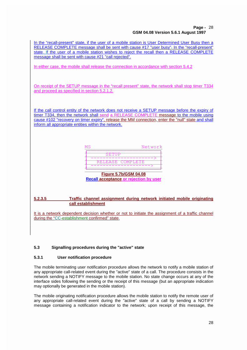
Page -GSM 04.08 Version 5.6.1 August 1997
28
28
In the “recall-present" state, if the user of a mobile station is User Determined User Busy then aRELEASE COMPLETE message shall be sent with cause #17 "user busy". In the “recall-present"state. If the user of a mobile station wishes to reject the recall then a RELEASE COMPLETEmessage shall be sent with cause #21 "call rejected".
In either case, the mobile shall release the connection in accordance with section 5.4.2
On receipt of the SETUP message in the “recall present” state, the network shall stop timer T334and proceed as specified in section 5.2.1.2.
If the call control entity of the network does not receive a SETUP message before the expiry oftimer T334, then the network shall send a RELEASE COMPLETE message to the mobile usingcause #102 "recovery on timer expiry", release the MM connection, enter the "null" state and shallinform all appropriate entities within the network.
MS Network�������������������������������������� �������������������������������RELEASE COMPLETE �����������������������> ���������������������������
Figure 5.7b/GSM 04.08Recall acceptance or rejection by user
5.2.3.5 Traffic channel assignment during network initiated mobile originatingcall establishment
It is a network dependent decision whether or not to initiate the assignment of a traffic channelduring the “CC-establishment confirmed” state.
5.3 Signalling procedures during the "active" state
5.3.1 User notification procedure
The mobile terminating user notification procedure allows the network to notify a mobile station ofany appropriate call-related event during the "active" state of a call. The procedure consists in thenetwork sending a NOTIFY message to the mobile station. No state change occurs at any of theinterface sides following the sending or the receipt of this message (but an appropriate indicationmay optionally be generated in the mobile station).
The mobile originating notification procedure allows the mobile station to notify the remote user ofany appropriate call-related event during the "active" state of a call by sending a NOTIFYmessage containing a notification indicator to the network; upon receipt of this message, the
Page -GSM 04.08 Version 5.6.1 August 1997
35
35
5.4 Call clearing
5.4.1 Terminology
The following terms are used in this Technical Specification in the description of clearingprocedures:
- A traffic channel (see GSM 04.03) is "connected" when the channel is part of a circuit-switched connection established according to this Technical Specification.
- A traffic channel is "disconnected" when the channel is no longer part of a circuit-switchedconnection, but is not yet available for use in a new connection.
5.4.2 Exception conditions
Under normal conditions, the call control entity of the mobile station or of the network initiates callclearing by sending a DISCONNECT message to its peer entity; then both entities follow theprocedures defined in sections 5.4.3 and 5.4.4 respectively.
As an exception to the above rule, the call control entity of the mobile station or of the network, inresponse to a SETUP or START CC or CC-ESTABLISHMENTRECALL or CC-
ESTABLISHMENT CONFIRMED or RECALL message, can reject a call by stopping all runningcall control timers, responding with a RELEASE COMPLETE message, releasing the MMconnection, and returning to the "null" state, provided no other response has previously been sent.
As a further exception, the call control entity of the network may initiate call clearing by stopping allrunning call control timers, sending a RELEASE message, starting timer T308, and entering the"release request" state.
NOTE: This way to initiate call clearing by sending a RELEASE message should notbe used by the network:
- if in-band tones/announcements are provided and the network decidesto use the procedure described in section 5.4.4.1;
- if the network wants to have the opportunity to respond to informationsent by the mobile station during call clearing.
A call control entity shall accept an incoming RELEASE COMPLETE message used to initiate thecall clearing even though the cause information element is not included.
A control entity shall accept an incoming RELEASE message used to initiate the call clearing eventhough the cause information element is not included.
Furthermore, a call control entity shall regard an incoming RELEASE COMPLETE message asconsistent with any of its states; a call control entity shall regard an incoming RELEASE messageas consistent with any of its states except the null state: a call control entity of the mobile stationshall regard an incoming DISCONNECT message as consistent with any of its call control statesexcept the "null" state, the "release request" state, and the "disconnect indication" state; a callcontrol entity of the network shall regard an incoming DISCONNECT message as consistent withany of its call control states except the "null" state and the "release request" state.
NOTE: This allows the introduction of shorter call clearing procedures in the future.