Embed Size (px)
DESCRIPTION
ECAL software development. Yuri Kharlov IHEP Protvino. Goals of simulations. ECAL consists of O(10 4 ) channels of 3 different lateral sizes Each channel contains O(10 2 ) samples - PowerPoint PPT Presentation
Citation preview
ECAL software development
Yuri KharlovIHEP Protvino
Goals of simulations ECAL consists of O(104) channels of 3 different lateral
sizes Each channel contains O(102) samples
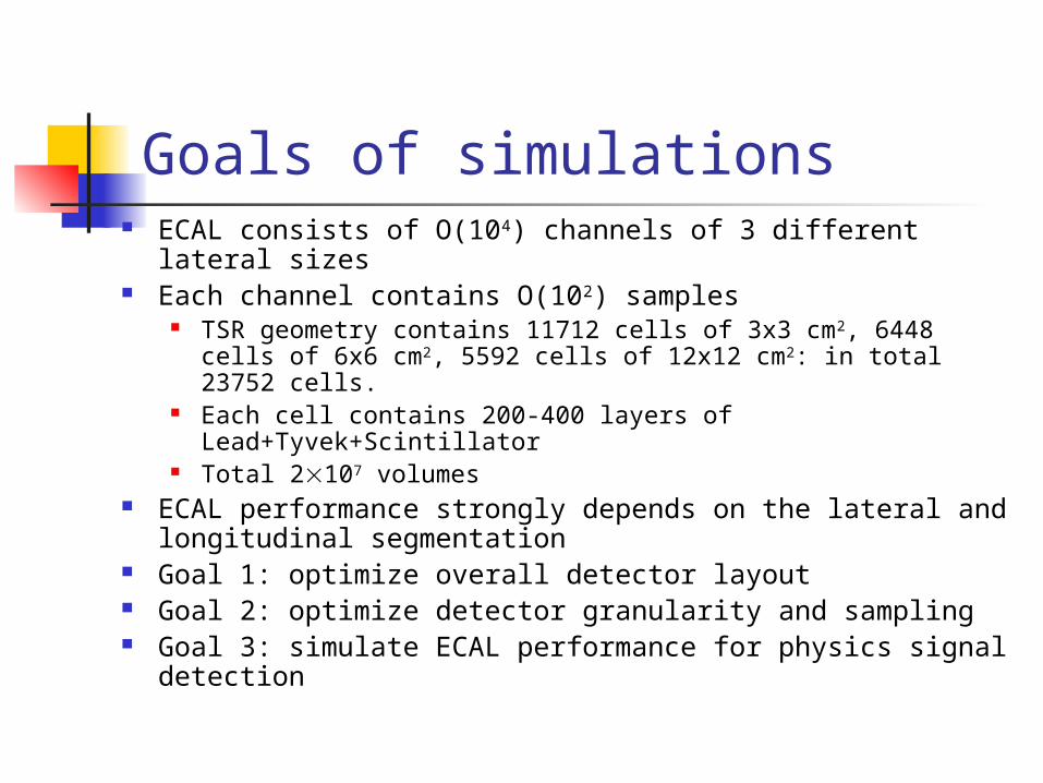
TSR geometry contains 11712 cells of 3x3 cm2, 6448 cells of 6x6 cm2, 5592 cells of 12x12 cm2: in total 23752 cells.
Each cell contains 200-400 layers of Lead+Tyvek+Scintillator
Total 2107 volumes ECAL performance strongly depends on the lateral and
longitudinal segmentation Goal 1: optimize overall detector layout Goal 2: optimize detector granularity and sampling Goal 3: simulate ECAL performance for physics signal
detection
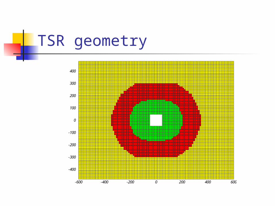
TSR geometry
-400
-300
-200
-100
0
100
200
300
400
-600 -400 -200 0 200 400 600
Why 109 volumes instead of 1? Main features of any calorimeter:
Energy resolution E/E Position resolution x Shape of a shower produced by different particles
Energy resolution depends on the cell sampling Position resolution is defined as a shower gravity center E/E and x affects the ECAL ability to measure particle
spectra (, 0) The granularity determines the detector cost As long as final granularity is still a subject to study, we
use 11-cm2 cells 109 volumes
Shower shape ECAL response to particles is a shower
Electromagnetic shower involves up to 25 cells Hadronic shower may fire 1-5 cells In high-multiplicity environment showers overlap
Shower shape is used in the reconstruction algorithm for overlapped shower unfolding and correct calculation of electomagnetic component of a shower
Although e.m. shower shape can be parametrized, such parameterization does not include fluctuations. Hadronic showers are not parameterized at all.
Only full simulation can provide correct ECAL response and thus allows to study ECAL performance
Geometry: ascii file vs C++ code Description of sizes and positions of 109 volumes is
useless Data base with such a straightforward description will
slow down simulations Coding of geometry in C++ program using profits from
geometry optimization tools provided by G3 and TGeo All 109 volumes are described in a very optimal
geometry hierarchy of 5 volumes embedded one into another
Performance test: 109 volumes vs 106 slow down simulation of 1 electron just in 4 times
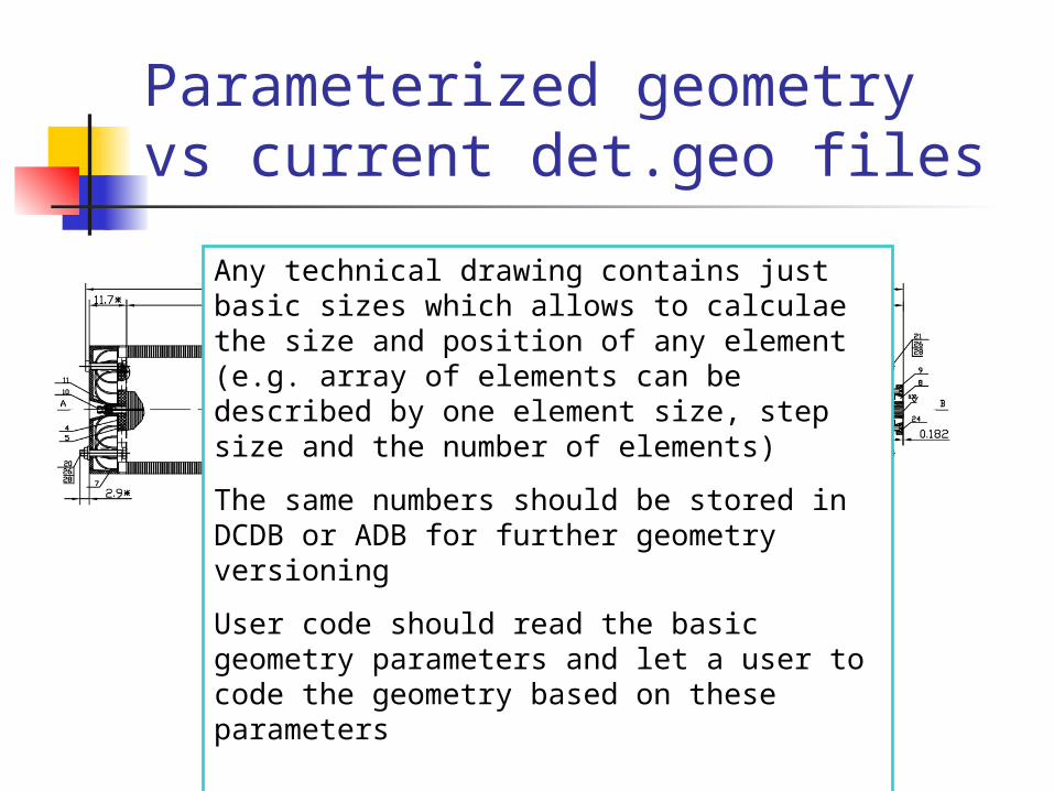
Parameterized geometry vs current det.geo files
Any technical drawing contains just basic sizes which allows to calculae the size and position of any element (e.g. array of elements can be described by one element size, step size and the number of elements)
The same numbers should be stored in DCDB or ADB for further geometry versioning
User code should read the basic geometry parameters and let a user to code the geometry based on these parameters
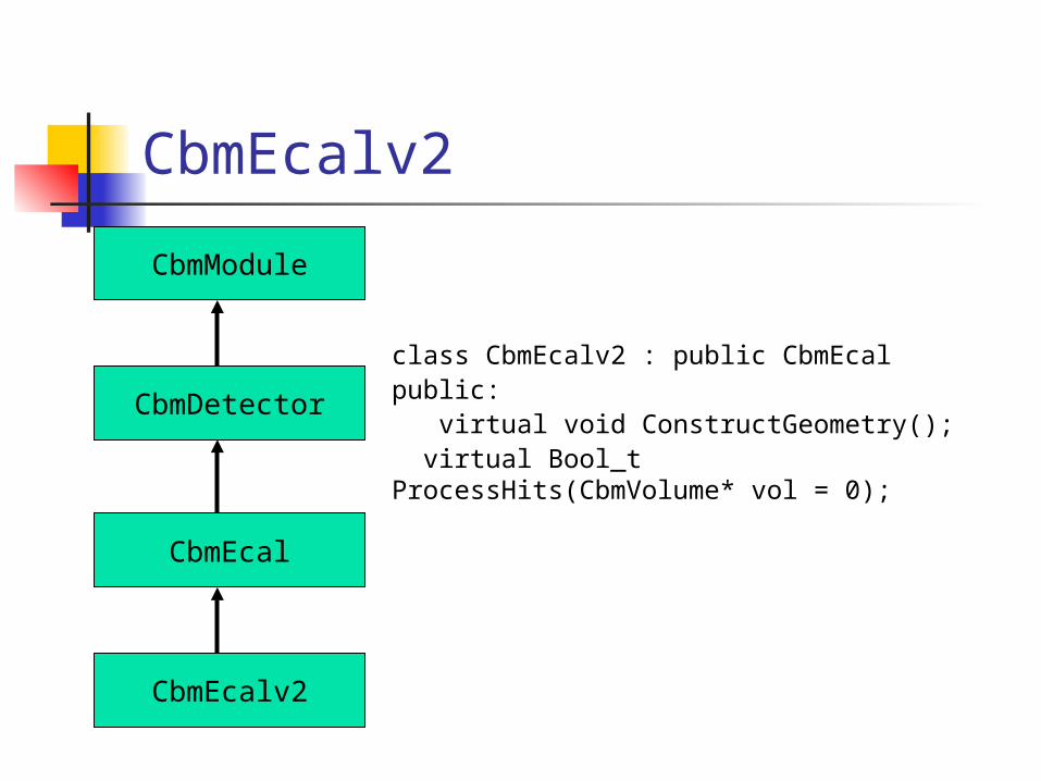
CbmEcalv2
CbmModule
CbmDetector
CbmEcal
CbmEcalv2
class CbmEcalv2 : public CbmEcalpublic: virtual void ConstructGeometry(); virtual Bool_t ProcessHits(CbmVolume* vol = 0);
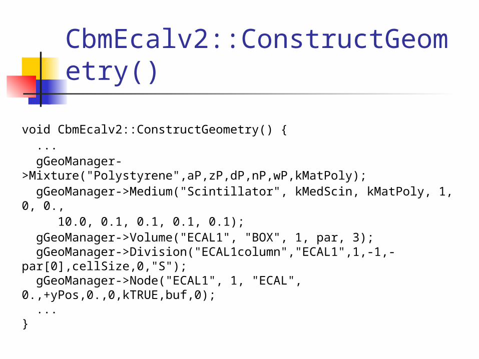
CbmEcalv2::ConstructGeometry()
void CbmEcalv2::ConstructGeometry() { ... gGeoManager->Mixture("Polystyrene",aP,zP,dP,nP,wP,kMatPoly); gGeoManager->Medium("Scintillator", kMedScin, kMatPoly, 1, 0, 0., 10.0, 0.1, 0.1, 0.1, 0.1); gGeoManager->Volume("ECAL1", "BOX", 1, par, 3); gGeoManager->Division("ECAL1column","ECAL1",1,-1,-par[0],cellSize,0,"S"); gGeoManager->Node("ECAL1", 1, "ECAL", 0.,+yPos,0.,0,kTRUE,buf,0); ...}

CbmEcalv2::ProcessHits()
ECAL MC point is stored each time when some energy is deposited:(gMC->Edep() != 0)
MC point:trackIdcellIdeLoss
wherecellId = iEcalBlock*1000000 + iColumn*1000 + iRow;
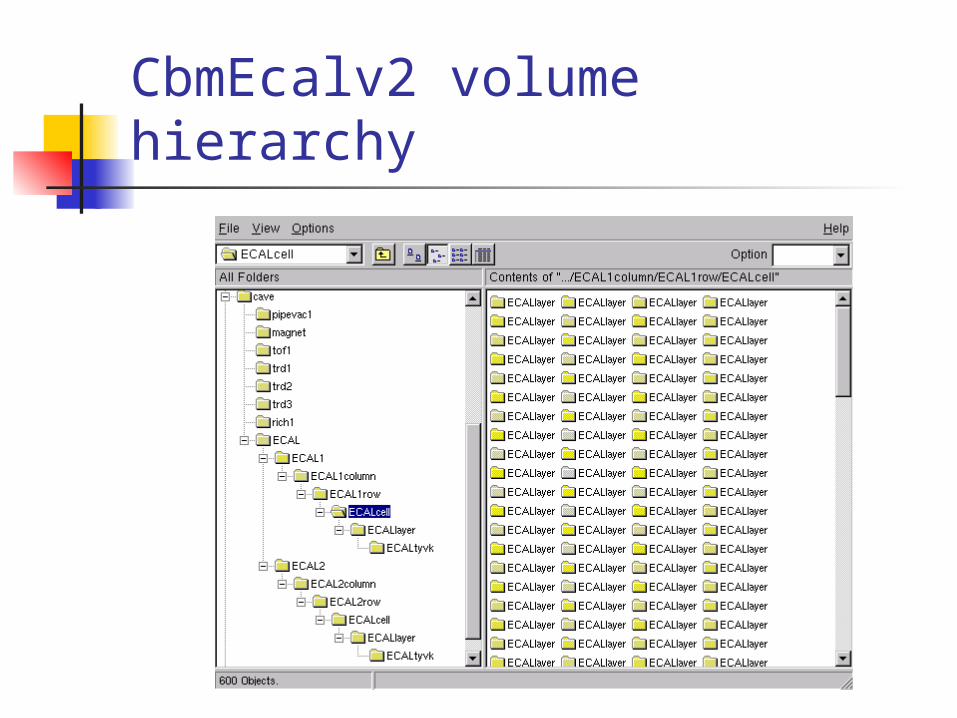
CbmEcalv2 volume hierarchy
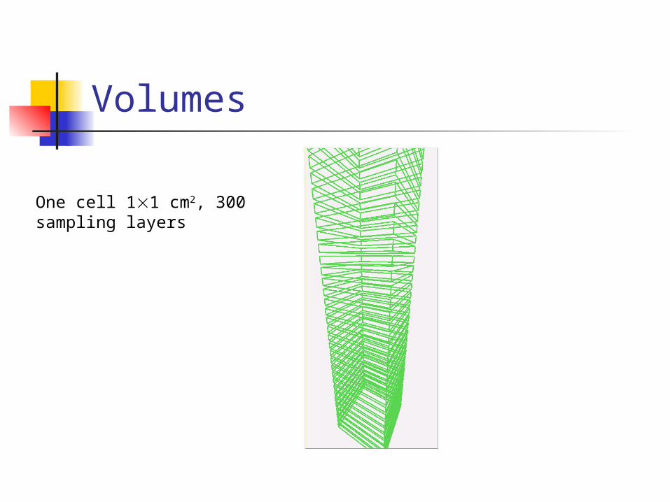
Volumes
One cell 11 cm2, 300 sampling layers
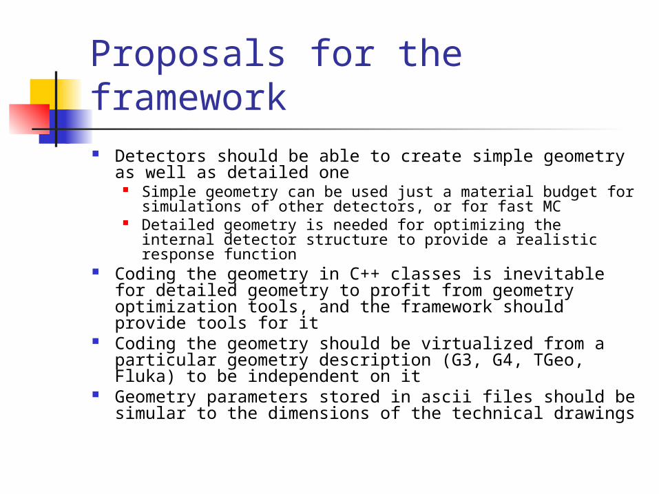
Proposals for the framework Detectors should be able to create simple geometry as
well as detailed one Simple geometry can be used just a material budget for
simulations of other detectors, or for fast MC Detailed geometry is needed for optimizing the internal
detector structure to provide a realistic response function Coding the geometry in C++ classes is inevitable for
detailed geometry to profit from geometry optimization tools, and the framework should provide tools for it
Coding the geometry should be virtualized from a particular geometry description (G3, G4, TGeo, Fluka) to be independent on it
Geometry parameters stored in ascii files should be simular to the dimensions of the technical drawings
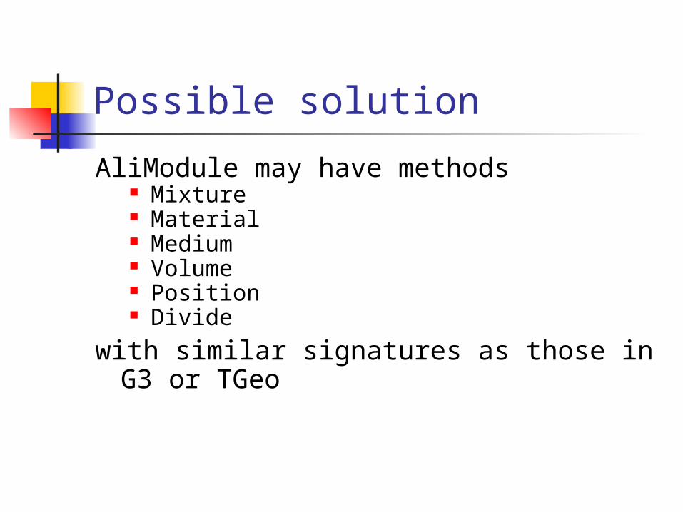
Possible solution
AliModule may have methods Mixture Material Medium Volume Position Divide
with similar signatures as those in G3 or TGeo