Embed Size (px)
Citation preview
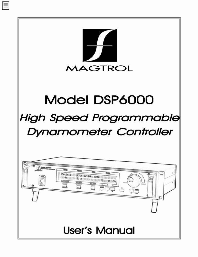
Model DSP6000Model DSP6000Model DSP6000Model DSP6000Model DSP6000High Speed PHigh Speed PHigh Speed PHigh Speed PHigh Speed Programmablerogrammablerogrammablerogrammablerogrammable
Dynamometer ControllerDynamometer ControllerDynamometer ControllerDynamometer ControllerDynamometer Controller
UserUserUserUserUser’s Manual’s Manual’s Manual’s Manual’s Manual
While every precaution has been exercisedin the compilation of this document,Magtrol, Inc. assumes no responsibilityfor errors or omissions. Additionally, noliability is assumed for any damages thatmay result from the use of the informationcontained within this publication.
LabVIEW® is a registered trademark ofNational Instruments Corporation.
RadioShack® is a registered trademark ofthe RadioShack Corporation.
wwwwwwwwwww.w.w.w.w.mmmmmagtragtragtragtragtroooool.cl.cl.cl.cl.cooooommmmm
Sales and TSales and TSales and TSales and TSales and Technical Assistanceechnical Assistanceechnical Assistanceechnical Assistanceechnical Assistance
Manufacturers of:
Motor Test Equipment!
Hysteresis Brakes and Clutches
70 Gardenville ParkwayBuffalo, New York 14224 USA
Tel: (716) 668-5555 or 1-800-828-7844Fax: (716) 668-8705
74M041 062200
MAGTROL, INC.MAGTROL, INC.MAGTROL, INC.MAGTROL, INC.MAGTROL, INC.
iii
Safety NotesSafety NotesSafety NotesSafety NotesSafety Notes
1. Make sure that all Magtrol dynamometers and electronic products are earth-grounded, to ensure personal safety and proper operation.
2. Check line voltage before operating the DSP6000.
3. Make sure that dynamometers and motors under test are equipped withappropriate safety guards.

iv
This page intentionally left blank.
v
TTTTTable of Contentsable of Contentsable of Contentsable of Contentsable of Contents
SALES AND TECHNICAL ASSISTANCE .............................................................................................. iiSAFETY NOTES..................................................................................................................................... iii1 - INTRODUCTION ................................................................................................................................ 1
About This Manual ............................................................................................................................................. 1Shipping .............................................................................................................................................................. 1
UNPACKING YOUR DSP6000 ............................................................................................................................................ 1About the Model DSP6000 Dynamometer Controller ....................................................................................... 1
FEATURES ......................................................................................................................................................................... 1SPECIFICATIONS ................................................................................................................................................................. 2
Front Panel .......................................................................................................................................................... 3Figure 1. Front Panel .................................................................................................................................... 3
ENABLING SECONDARY FUNCTIONS ..................................................................................................................................... 3FRONT PANEL CONTROLS AND BUTTONS ............................................................................................................................. 4
Vacuum Fluorescent Display (VFD) .................................................................................................................. 5STATUS DISPLAY MESSAGES .............................................................................................................................................. 5DISPLAYING DESIRED INFORMATION .................................................................................................................................... 5
Rear Panel ........................................................................................................................................................... 6Figure 2. Rear Panel ..................................................................................................................................... 6Figure 3. Brake Connector ............................................................................................................................ 6Figure 4. Accessory Torque/Speed Output .................................................................................................... 6Figure 5. Dynamometer Connector ............................................................................................................... 6
REAR PANEL FUNCTIONS .................................................................................................................................................... 7
2 - ABOUT THE PID LOOP..................................................................................................................... 8P (Proportional Gain) ......................................................................................................................................... 8I (Integral) .......................................................................................................................................................... 8D (Derivative) .................................................................................................................................................... 8
Figure 6. PID Loop ....................................................................................................................................... 8Setting The Correct PID'S For Your Motor ........................................................................................................ 8
3 - INSTALLATION................................................................................................................................ 10Setting Unit for Line Voltage ........................................................................................................................... 10
Figure 7. Cover for Voltage Selector, Fuses ............................................................................................... 10Checking Your DSP6000 .................................................................................................................................. 10
4 - THE DSP6000 AS A STAND-ALONE UNIT (LOCAL CONTROL) ................................................. 12Setting Desired Operating Parameters .............................................................................................................. 12
SET DISPLAY TO DESIRED POWER UNITS (WATTS OR HP) .................................................................................................. 12SET DISPLAY TO DESIRED TORQUE UNITS ......................................................................................................................... 12SET UP DISPLAY FOR DYNAMOMETER ............................................................................................................................... 12SET UP COMMUNICATIONS WITH PC ................................................................................................................................. 12SET UP AUXILIARY INPUT ................................................................................................................................................ 12SET TORQUE CONTROL .................................................................................................................................................... 12SET SPEED CONTROL ....................................................................................................................................................... 13SET OPEN LOOP CONTROL ............................................................................................................................................... 13SET UP I/O PARAMETERS ................................................................................................................................................ 13
Setting Dynamometer Load .............................................................................................................................. 14Using Internal Memory ..................................................................................................................................... 14
STORING DATA POINTS .................................................................................................................................................... 14RECALLING DATA POINTS ................................................................................................................................................ 14
vi
EXITING THE MEMORY MODE .......................................................................................................................................... 14CLEARING THE MEMORY .................................................................................................................................................. 14
5 - THE DSP6000 WITH A PC (REMOTE CONTROL) ......................................................................... 15About the GPIB Interface ................................................................................................................................. 15
Figure 8. GPIB (IEEE-488) Interface ......................................................................................................... 15INSTALLING THE GPIB (IEEE-488) CONNECTOR CABLE ................................................................................................... 15CHANGING THE GPIB PRIMARY ADDRESS ......................................................................................................................... 15
Checking the DSP6000-To-PC Connection ...................................................................................................... 16Programming .................................................................................................................................................... 16
CODES FOR CR - LF ....................................................................................................................................................... 16DSP6000 Command Set ................................................................................................................................... 16
COMMAND SET FOR DSP6000 ......................................................................................................................................... 17Acquiring Speed-Torque Data .......................................................................................................................... 20Selecting the Baud Rate for the RS-232 Interface ............................................................................................ 20
Figure 9. Connector Pin-Out ...................................................................................................................... 20
6 - CALIBRATION ................................................................................................................................. 21Closed-Box Calibration .................................................................................................................................... 21Calibration Schedule ......................................................................................................................................... 21Basic Calibration Process ................................................................................................................................. 21
INITIAL CALIBRATION PROCEDURE .................................................................................................................................... 21TORQUE OFFSET AND GAIN .............................................................................................................................................. 21ACCESSORY TORQUE OFFSET AND GAIN ............................................................................................................................ 22AUXILIARY INPUT OFFSET AND GAIN ................................................................................................................................ 22ALTERNATE CALIBRATION PROCEDURE .............................................................................................................................. 22
Figure 10. Alternative Calibration ................................................................................................................ 23
7 - TROUBLESHOOTING ..................................................................................................................... 24APPENDIX A: LABVIEW® PROGRAMMING EXAMPLES................................................................. 25
Simple Read ...................................................................................................................................................... 25Torque Stabilized .............................................................................................................................................. 26Speed Stabilized ................................................................................................................................................ 27
APPENDIX B: INERTIA CORRECTION .............................................................................................. 28Inertial Effect on Motor Test Data .................................................................................................................... 28Procedure for Inertia Correction ....................................................................................................................... 28
KEY CONDITIONS ............................................................................................................................................................ 28
APPENDIX C: FRONT PANEL/DISPLAY MENU FLOW CHARTS..................................................... 29Dyno Setup Menu ............................................................................................................................................. 29Com Setup Menu .............................................................................................................................................. 30Aux Setup Menu ............................................................................................................................................... 31Power Units Menu ............................................................................................................................................ 31Torque Units Menu ........................................................................................................................................... 32
APPENDIX D: SCHEMATICS .............................................................................................................. 33Encoder/Switch Board ...................................................................................................................................... 33Power Supply .................................................................................................................................................... 33DSP & Memory ................................................................................................................................................ 34Analog I/O ........................................................................................................................................................ 35
GLOSSARY OF ABBREVIATIONS AND TERMS ................................................................................ 36MAGTROL LIMITED WARRANTY ....................................................................................................... 37
1
ABOUT THIS MANUAL
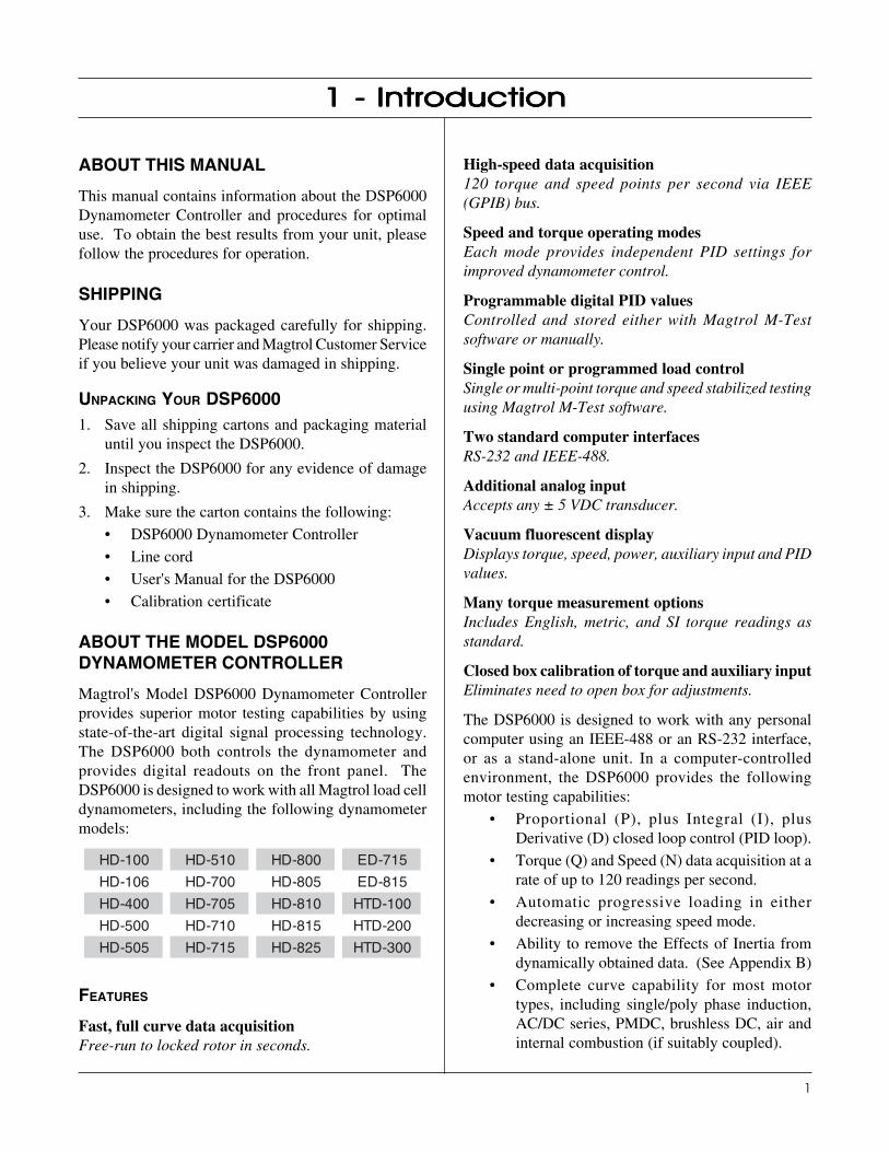
This manual contains information about the DSP6000Dynamometer Controller and procedures for optimaluse. To obtain the best results from your unit, pleasefollow the procedures for operation.
SHIPPING
Your DSP6000 was packaged carefully for shipping.Please notify your carrier and Magtrol Customer Serviceif you believe your unit was damaged in shipping.
UNPACKING YOUR DSP60001. Save all shipping cartons and packaging material
until you inspect the DSP6000.
2. Inspect the DSP6000 for any evidence of damagein shipping.
3. Make sure the carton contains the following:
• DSP6000 Dynamometer Controller
• Line cord
• User's Manual for the DSP6000
• Calibration certificate
ABOUT THE MODEL DSP6000DYNAMOMETER CONTROLLER
Magtrol's Model DSP6000 Dynamometer Controllerprovides superior motor testing capabilities by usingstate-of-the-art digital signal processing technology.The DSP6000 both controls the dynamometer andprovides digital readouts on the front panel. TheDSP6000 is designed to work with all Magtrol load celldynamometers, including the following dynamometermodels:
001-DH 015-DH 008-DH 517-DE
601-DH 007-DH 508-DH 518-DE
004-DH 507-DH 018-DH 001-DTH
005-DH 017-DH 518-DH 002-DTH
505-DH 517-DH 528-DH 003-DTH
FEATURES
Fast, full curve data acquisitionFree-run to locked rotor in seconds.
1 - Introduction1 - Introduction1 - Introduction1 - Introduction1 - Introduction
High-speed data acquisition120 torque and speed points per second via IEEE(GPIB) bus.
Speed and torque operating modesEach mode provides independent PID settings forimproved dynamometer control.
Programmable digital PID valuesControlled and stored either with Magtrol M-Testsoftware or manually.
Single point or programmed load controlSingle or multi-point torque and speed stabilized testingusing Magtrol M-Test software.
Two standard computer interfacesRS-232 and IEEE-488.
Additional analog inputAccepts any ± 5 VDC transducer.
Vacuum fluorescent displayDisplays torque, speed, power, auxiliary input and PIDvalues.
Many torque measurement optionsIncludes English, metric, and SI torque readings asstandard.
Closed box calibration of torque and auxiliary inputEliminates need to open box for adjustments.
The DSP6000 is designed to work with any personalcomputer using an IEEE-488 or an RS-232 interface,or as a stand-alone unit. In a computer-controlledenvironment, the DSP6000 provides the followingmotor testing capabilities:
• Proportional (P), plus Integral (I), plusDerivative (D) closed loop control (PID loop).
• Torque (Q) and Speed (N) data acquisition at arate of up to 120 readings per second.
• Automatic progressive loading in eitherdecreasing or increasing speed mode.
• Ability to remove the Effects of Inertia fromdynamically obtained data. (See Appendix B)
• Complete curve capability for most motortypes, including single/poly phase induction,AC/DC series, PMDC, brushless DC, air andinternal combustion (if suitably coupled).
2
Magtrol Model DSP6000 Dynamometer ControllerChapter 1 - Introduction
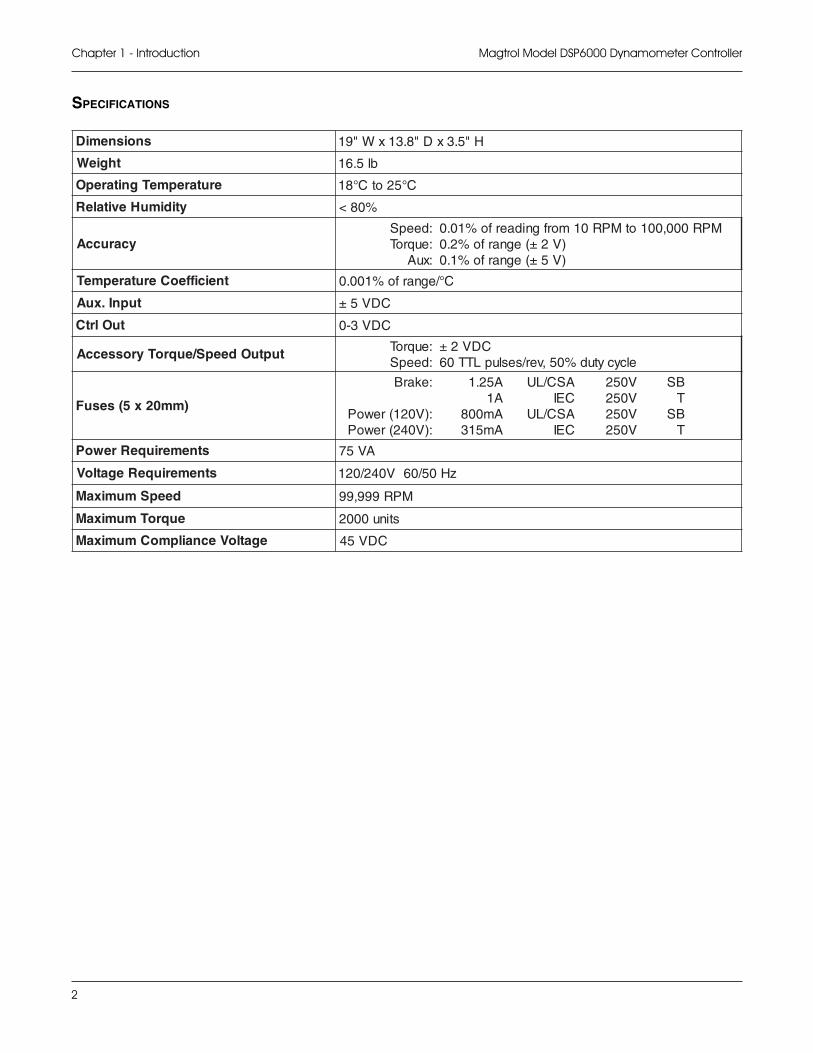
SPECIFICATIONS
snoisnemiD H"5.3xD"8.31xW"91
thgieW bl5.61
erutarepmeTgnitarepO C°52otC°81
ytidimuHevitaleR %08<
ycaruccA:deepS:euqroT:xuA
MPR000,001otMPR01morfgnidaerfo%10.0)V2±(egnarfo%2.0)V5±(egnarfo%1.0
tneiciffeoCerutarepmeT C°/egnarfo%100.0
tupnI.xuA CDV5±
tuOlrtC CDV3-0
tuptuOdeepS/euqroTyrosseccA :euqroT:deepS
CDV2±elcycytud%05,ver/seslupLTT06
)mm02x5(sesuF
:ekarB
:)V021(rewoP:)V042(rewoP
A52.1A1Am008Am513
ASC/LUCEIASC/LUCEI
052 VV052V052V052
BSTBST
stnemeriuqeRrewoP AV57
stnemeriuqeRegatloV zH05/06V042/021
deepSmumixaM MPR999,99
euqroTmumixaM stinu0002
egatloVecnailpmoCmumixaM CDV54
3
Magtrol Model DSP6000 Dynamometer Controller Chapter 1 - Introduction
FRONT PANEL
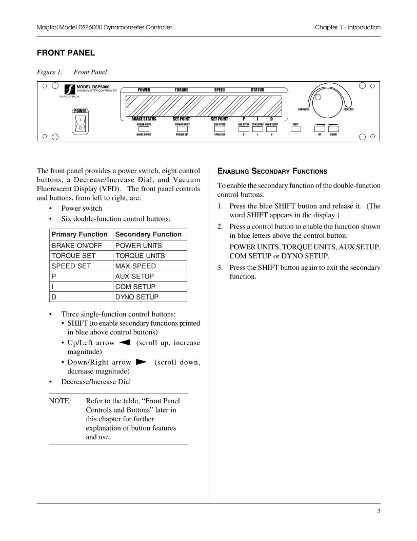
Figure 1. Front Panel
MODEL DSP6000DYNAMOMETER CONTROLLER
The front panel provides a power switch, eight controlbuttons, a Decrease/Increase Dial, and VacuumFluorescent Display (VFD). The front panel controlsand buttons, from left to right, are:
• Power switch
• Six double-function control buttons:
noitcnuFyramirP noitcnuFyradnoceS
FFO/NOEKARB STINUREWOP
TESEUQROT STINUEUQROT
TESDEEPS DEEPSXAM
P PUTESXUA
I PUTESMOC
D PUTESONYD
• Three single-function control buttons:• SHIFT (to enable secondary functions printed
in blue above control buttons)
• Up/Left arrow ! (scroll up, increasemagnitude)
• Down/Right arrow " (scroll down,decrease magnitude)
• Decrease/Increase Dial
NOTE: Refer to the table, “Front PanelControls and Buttons” later inthis chapter for furtherexplanation of button featuresand use.
ENABLING SECONDARY FUNCTIONS
To enable the secondary function of the double-functioncontrol buttons:
1. Press the blue SHIFT button and release it. (Theword SHIFT appears in the display.)
2. Press a control button to enable the function shownin blue letters above the control button:
POWER UNITS, TORQUE UNITS, AUX SETUP,COM SETUP or DYNO SETUP.
3. Press the SHIFT button again to exit the secondaryfunction.
4
Magtrol Model DSP6000 Dynamometer ControllerChapter 1 - Introduction
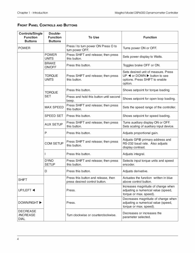
FRONT PANEL CONTROLS AND BUTTONS
elgniS/slortnoCnoitcnuFsnottuB
-elbuoDnoitcnuFsnottuB
esUoT noitcnuF
REWOPotOsserPNOrewopnrutotIsserP
.FFOrewopnrut.FFOroNOrewopsnruT
REWOPSTINU
sserpneht;esaelerdnaTFIHSsserP.nottubsiht
.sttaWotyalpsidrewopsteS
EKARBFFO/NO
.nottubsihtsserP .NOroFFOekarbselggoT
EUQROTSTINU
sserpneht;esaelerdnaTFIHSsserP.nottubsiht
sserP.erusaemfotinuderisedsteSPU ! NWODro " eesotnottub
elbaneotTFIHSsserP.snoitpo.noitpo
EUQROTTES
.nottubsihtsserP gnidaoleuqrotroftnioptesswohS
dnoceslitnunottubsihtdlohdnasserP.peeb
.gnidaolpoolneporoftnioptesswohS
DEEPSXAMsserpneht;esaelerdnaTFIHSsserP
.nottubsiht.rellortnocehtfoegnardeepsehtsteS
TESDEEPS .nottubsihtsserP .gnidaoldeepsroftnioptesswohS
PUTESXUAsserpneht;esaelerdnaTFIHSsserP
.nottubsiht.FFOroNOyalpsidyrailixuasnruT
.ecivedtupniyrailixuafognilacssteS
P .nottubsihtsserP .niaglanoitroporpstsujdA
PUTESMOCsserpneht;esaelerdnaTFIHSsserP
.nottubsiht
dnasserddayramirpBIPGstsujdAstsujdaoslA.etarduab232-SR
.tsartnocyalpsid
I .nottubsihtsserP .largetnistsujdA
ONYDPUTES
sserpneht;esaelerdnaTFIHSsserP.nottubsiht
deepsdnastinueuqrottupnistceleS.redocne
D .nottubsihtsserP .evitaviredstsujdA
TFIHSneht,esaelerdnanottubsihtsserP
.nottublortnocderisedsserpeulbninettirwnoitcnufehtsetautcA
.nottublortnocevoba
TFEL/PU ! .sserPnehwegnahcfoedutingamsesaercnI
,deeps(eulavlaciremunagnitsujda.)deeps.xamroeuqrot
THGIR/NWOD " .sserPnehwegnahcfoedutingamsesaerceD
,deeps(eulavlaciremunagnitsujda.)deeps.xamroeuqrot
ESAERCEDESAERCNI/
LAID.esiwkcolcretnuocroesiwkcolcnruT
ehtsesaercnirosesaerceD.detcelesretemarap
5
Magtrol Model DSP6000 Dynamometer Controller Chapter 1 - Introduction
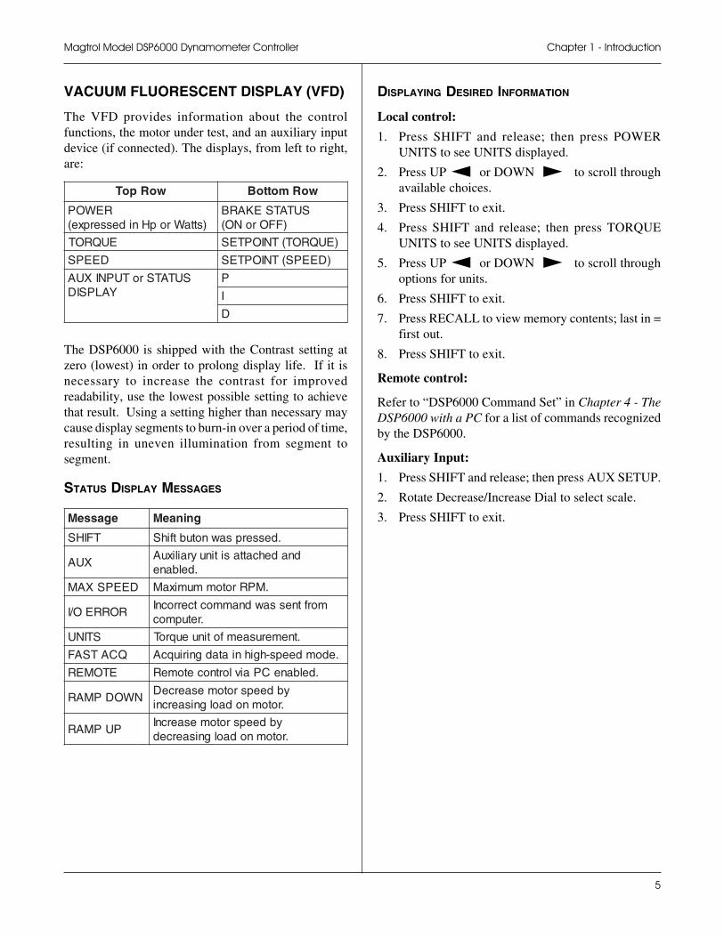
VACUUM FLUORESCENT DISPLAY (VFD)
The VFD provides information about the controlfunctions, the motor under test, and an auxiliary inputdevice (if connected). The displays, from left to right,are:
woRpoT woRmottoB
REWOP)sttaWropHnidesserpxe(
SUTATSEKARB)FFOroNO(
EUQROT )EUQROT(TNIOPTES
DEEPS )DEEPS(TNIOPTES
SUTATSroTUPNIXUAYALPSID
P
I
D
The DSP6000 is shipped with the Contrast setting atzero (lowest) in order to prolong display life. If it isnecessary to increase the contrast for improvedreadability, use the lowest possible setting to achievethat result. Using a setting higher than necessary maycause display segments to burn-in over a period of time,resulting in uneven illumination from segment tosegment.
STATUS DISPLAY MESSAGES
egasseM gninaeM
TFIHS .desserpsawnotubtfihS
XUAdnadehcattasitinuyrailixuA
.delbane
DEEPSXAM .MPRrotommumixaM
RORREO/ImorftnessawdnammoctcerrocnI
.retupmoc
STINU .tnemerusaemfotinueuqroT
QCATSAF .edomdeeps-hgihniatadgniriuqcA
ETOMER .delbaneCPaivlortnocetomeR
NWODPMARybdeepsrotomesaerceD.rotomnodaolgnisaercni
PUPMARybdeepsrotomesaercnI
.rotomnodaolgnisaerced
DISPLAYING DESIRED INFORMATION
Local control:
1. Press SHIFT and release; then press POWERUNITS to see UNITS displayed.
2. Press UP ! or DOWN " to scroll throughavailable choices.
3. Press SHIFT to exit.
4. Press SHIFT and release; then press TORQUEUNITS to see UNITS displayed.
5. Press UP ! or DOWN " to scroll throughoptions for units.
6. Press SHIFT to exit.
7. Press RECALL to view memory contents; last in =first out.
8. Press SHIFT to exit.
Remote control:
Refer to “DSP6000 Command Set” in Chapter 4 - TheDSP6000 with a PC for a list of commands recognizedby the DSP6000.
Auxiliary Input:
1. Press SHIFT and release; then press AUX SETUP.
2. Rotate Decrease/Increase Dial to select scale.
3. Press SHIFT to exit.
6
Magtrol Model DSP6000 Dynamometer ControllerChapter 1 - Introduction
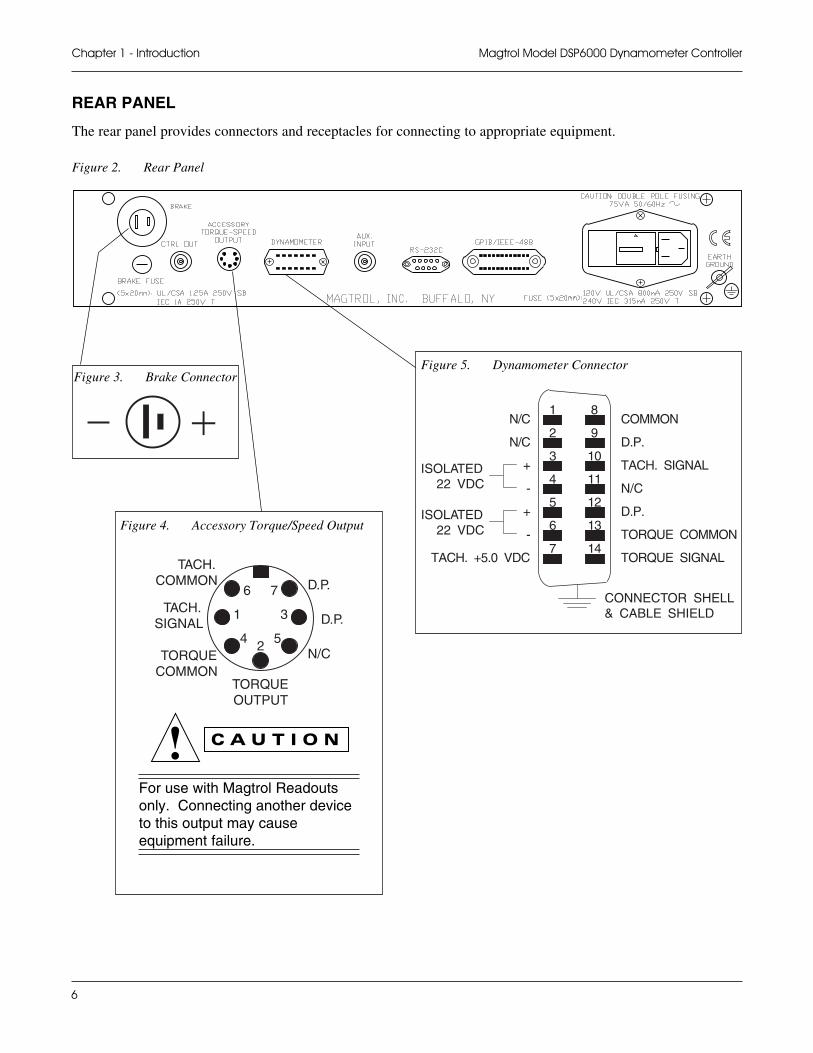
REAR PANEL
The rear panel provides connectors and receptacles for connecting to appropriate equipment.
Figure 2. Rear Panel
For use with Magtrol Readoutsonly. Connecting another deviceto this output may causeequipment failure.
Figure 3. Brake Connector
1
2
3
4
5
6
7
8
9
10
11
12
13
14
COMMON
D.P.
TACH. SIGNAL
N/C
D.P.
TORQUE COMMON
TORQUE SIGNAL
N/C
N/C
+
-
+
-
TACH. +5.0 VDC
ISOLATED22 VDC
ISOLATED22 VDC
CONNECTOR SHELL& CABLE SHIELD
Figure 5. Dynamometer Connector
6 7
1 3
4 52
D.P.
D.P.
N/C
TORQUEOUTPUT
TORQUECOMMON
TACH.COMMON
TACH.SIGNAL
Figure 4. Accessory Torque/Speed Output
7
Magtrol Model DSP6000 Dynamometer Controller Chapter 1 - Introduction
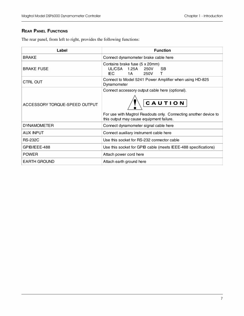
REAR PANEL FUNCTIONS
The rear panel, from left to right, provides the following functions:
Label Function
BRAKE Connect dynamometer brake cable here
BRAKE FUSEContains brake fuse (5 x 20mm) UL/CSA 1.25A 250V SB IEC 1A 250V T
CTRL OUTConnect to Model 5241 Power Amplifier when using HD-825Dynamometer
ACCESSORY TORQUE-SPEED OUTPUT
Connect accessory output cable here (optional).
For use with Magtrol Readouts only. Connecting another device tothis output may cause equipment failure.
DYNAMOMETER Connect dynamometer signal cable here
AUX INPUT Connect auxiliary instrument cable here
RS-232C Use this socket for RS-232 connector cable
GPIB/IEEE-488 Use this socket for GPIB cable (meets IEEE-488 specifications)
POWER Attach power cord here
EARTH GROUND Attach earth ground here
8
2 - About the PID L2 - About the PID L2 - About the PID L2 - About the PID L2 - About the PID Loopoopoopoopoop
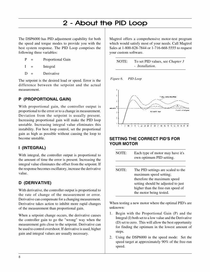
The DSP6000 has PID adjustment capability for boththe speed and torque modes to provide you with thebest system response. The PID Loop comprises thefollowing three variables:
P = Proportional Gain
I = Integral
D = Derivative
The setpoint is the desired load or speed. Error is thedifference between the setpoint and the actualmeasurement.
P (PROPORTIONAL GAIN)
With proportional gain, the controller output isproportional to the error or to a change in measurement.Deviation from the setpoint is usually present.Increasing proportional gain will make the PID loopunstable. Increasing integral value eliminates thisinstability. For best loop control, set the proportionalgain as high as possible without causing the loop tobecome unstable.
I (INTEGRAL)
With integral, the controller output is proportional tothe amount of time the error is present. Increasing theintegral value eliminates the offset from the setpoint. Ifthe response becomes oscillatory, increase the derivativevalue.
D (DERIVATIVE)
With derivative, the controller output is proportional tothe rate of change of the measurement or error.Derivative can compensate for a changing measurement.Derivative takes action to inhibit more rapid changesof the measurement than proportional gain.
When a setpoint change occurs, the derivative causesthe controller gain to go the "wrong" way when themeasurement gets close to the setpoint. Derivative canbe used to control overshoot. If derivative is used, highergain and integral values are usually necessary.
Magtrol offers a comprehensive motor-test programwhich would satisfy most of your needs. Call MagtrolSales at 1-800-828-7844 or 1-716-668-5555 to requestyour custom software.
NOTE: To set PID values, see Chapter 3- Installation.
Figure 6. PID Loop
SETTING THE CORRECT PID'S FORYOUR MOTOR
NOTE: Each type of motor may have it'sown optimum PID setting.
NOTE: The PID settings are scaled to themaximum speed setting;therefore the maximum speedsetting should be adjusted to justhigher than the free-run speed ofthe motor being tested.
When testing a new motor where the optimal PID's areunknown:
1. Begin with the Proportional Gain (P) and theIntegral (I) both set to a low value and the Derivative(D) set to zero. This will allow the best opportunityfor finding the optimum in the lowest amount ofsteps.
2. Using the DSP6000 in the speed mode: Set thespeed target at approximately 90% of the free-runspeed.
9
Magtrol Model DSP6000 Dynamometer Controller Chapter 2 - About the PID Loop
The larger the I value the faster the DSP6000 will moveto the target number, but an I value too large will causeinstability (oscillation). Once the optimum values arefound, these steps should be repeated at differentpercentages of speed to ensure that they are the bestcombination for the entire speed range.
NOTE: The PID values for a speedstabilized test and a ramp testwill vary. Therefore, PIDadjustments may be needed whenchanging from a stabilized test toramp testing with the samemotor.
The D value has little or no effect on this type of testing,therefore the D value can remain at zero.
3. Turn the brake to the ON position and observe howthe actual speed moves toward the target speed.
4. If the speed moves slowly or not at all, increase theP until the target speed is achieved.
5. Turn the brake OFF.
6. Turn the brake ON and note how fast the free-runspeed changes to the target speed.
7. If the speed conversion does not happen quickly,increase the I value.
8. Repeat steps 4-7 until the motor moves from thefree-run to the target speed as quickly as possiblewithout excessive overshoot.
Example:
Motor type: ACFree-Run speed: 1750
1. Set maximum speed to 1800
2. Set P = 5 I =5 D = 0
3. Set target speed to 1600
4. Turn brake ON—no response
5. Move P value to 10—still slow, not reaching 1600
Note: Increasing the P more will notincrease the operatingcharacteristics without firstincreasing the I value.
6. Turn brake OFF
7. Move I value to 10
8. Turn brake ON—Reaching 1600 very slowly
9. With the brake OFF, adjust the P to 15
10. Turn the brake ON—never reaching 1600
11. Turn the brake OFF. Decrease the P to 10 andincrease the I to 15
12. Turn the brake ON—reaches 1600 Faster
13. Turn the brake OFF. Increase I to 20
14. Turn the brake ON—reaches 1600 Faster
15. Turn the brake OFF. Increase I to 25
16. Turn the brake ON—reaches 1600 Faster
17. Turn the brake OFF. Repeat
10
Before installing your DSP6000, you should becomefamiliar with the front and rear panels, as outlined inChapter 1-Introduction.
Make sure the DSP6000 is earthgrounded before starting!
SETTING UNIT FOR LINE VOLTAGE
The DSP6000 will operate with either of the followingpower sources:
• 120V 50/60 Hz
• 240V 50/60 Hz
1. Find the line cord receptacle on rear panel. Theline cord is a detachable NEMA Standard 3 wire.
2. Make sure the selector matches the power source(numbers should match the line voltage).
If not:
• Locate the power entry module.
• Remove the line cord.
• Insert a screwdriver into the slot and open thecover.
• Slide the voltage selector so the desired linevoltage appears in the window.
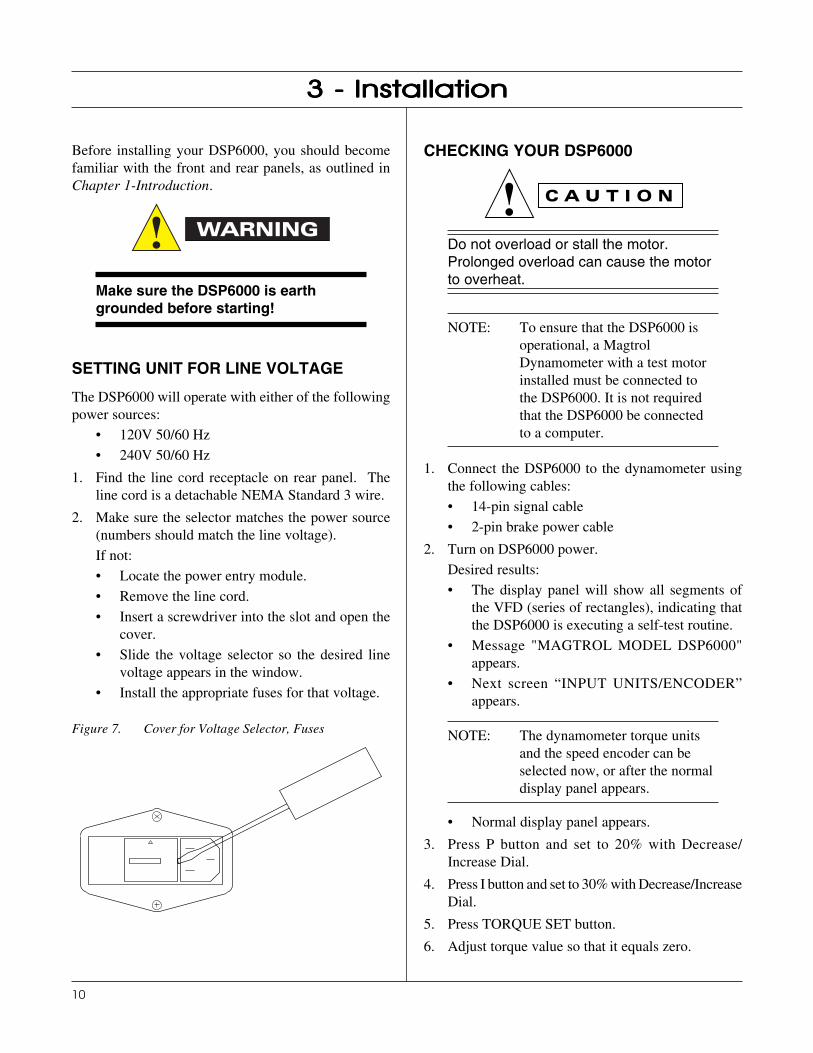
• Install the appropriate fuses for that voltage.
Figure 7. Cover for Voltage Selector, Fuses
CHECKING YOUR DSP6000
Do not overload or stall the motor.Prolonged overload can cause the motorto overheat.
NOTE: To ensure that the DSP6000 isoperational, a MagtrolDynamometer with a test motorinstalled must be connected tothe DSP6000. It is not requiredthat the DSP6000 be connectedto a computer.
1. Connect the DSP6000 to the dynamometer usingthe following cables:
• 14-pin signal cable
• 2-pin brake power cable
2. Turn on DSP6000 power.
Desired results:• The display panel will show all segments of
the VFD (series of rectangles), indicating thatthe DSP6000 is executing a self-test routine.
• Message "MAGTROL MODEL DSP6000"appears.
• Next screen “INPUT UNITS/ENCODER”appears.
NOTE: The dynamometer torque unitsand the speed encoder can beselected now, or after the normaldisplay panel appears.
• Normal display panel appears.
3. Press P button and set to 20% with Decrease/Increase Dial.
4. Press I button and set to 30% with Decrease/IncreaseDial.
5. Press TORQUE SET button.
6. Adjust torque value so that it equals zero.
3 - Installation3 - Installation3 - Installation3 - Installation3 - Installation
11
Magtrol Model DSP6000 Dynamometer Controller Chapter 3 - Installation
7. Start the test motor.
8. Allow the motor speed to stabilize at its no-loadspeed for a few seconds.
9. Press the BRAKE ON/OFF button to ON.
10. Press the TORQUE SET button.
11. Turn the Decrease/Increase Dial clockwise.
Desired results:
• The torque reading will increase.
As brake power is applied, load is applied tothe motor. The applied torque increases as theDecrease/Increase Dial is turned clockwise. Formost motors, loading is indicated by motorspeed reduction.
12. Reduce the torque load to zero by turning theDecrease/Increase Dial counterclockwise.
Desired results:
• The torque reading will decrease.
13. Press the BRAKE ON/OFF Button to OFF.
14. Use the SHIFT button to enable the MAX SPEEDfunction.
15. Turn the Decrease/Increase Dial clockwise until theMAX speed reading is slightly greater than themotor’s free-run speed.
16. Press the SPEED SET button - Turn theDECREASE/INCREASE DIAL until speedsetpoint no longer increases (max. speed setting).
17. Press P button and set to 10%.
18. Press I button and set to 15%.
19. Press the BRAKE ON/OFF button ON.
20. Press the SPEED SET button.
21. Turn the Decrease/Increase Dial counterclockwise.
Desired results:
• The motor speed will decrease.
NOTE: Adjust the motor’s stability byadjusting the PID values. SeeChapter 2 - About the PID Loop.
22. Turn off power to the test motor.
NOTE: If the desired results did notoccur, please see Chapter 7 -Troubleshooting.
12
NOTE: Although the DSP6000 can beused without a computer, it willonly perform at a fraction of itscapability.
SETTING DESIRED OPERATINGPARAMETERS
NOTE: See Appendix C: Front Panel/Display Menu Flow Charts.
SET DISPLAY TO DESIRED POWER UNITS (WATTS
OR HP)1. Press and release SHIFT.
2. Press POWER UNITS.
SET DISPLAY TO DESIRED TORQUE UNITS
1. Press and release SHIFT.
2. Press TORQUE UNITS.
3. Continue pressing TORQUE UNITS until thedesired unit of measure is displayed.
4. Press SHIFT to exit.
SET UP DISPLAY FOR DYNAMOMETER
1. Press and release SHIFT.
2. Press DYNO SETUP.
3. Press TORQUE UNITS until input unit matchesdynamometer.
4. Press ENCODER until selection matches encoderinstalled on dynamometer (60 bit = standard).
5. Press SHIFT to exit.
SET UP COMMUNICATIONS WITH PC(If necessary)
1. Press and release SHIFT.
2. Then press COM SETUP.
3. Select GPIB ADDRESS. Press GPIB ADDRS untilappropriate address appears. (See “Changing theGPIB Primary Address” in Chapter 5 - TheDSP6000 with a PC (Remote Control.)
4. Select baud rate. Press RS-232 BAUD untilappropriate baud rate appears.
5. Press SHIFT to exit.
SET UP AUXILIARY INPUT
(If necessary)
See “Displaying Desired Information” in Chapter 1 -Introduction.
SET TORQUE CONTROL
NOTE: See Chapter 2 - About the PIDLoop.
1. Press the TORQUE SET button.
2. Use the UP ! and DOWN " buttons and theDecrease/Increase Dial to adjust the setpoint to zero.
3. Press the P button.
4. Use the Decrease/Increase Dial to preset an initialvalue of 20.
5. Press the I button.
6. Use the Decrease/Increase Dial to preset an initialvalue of 30.
7. Press the D button.
8. Use the Decrease/Increase Dial to preset an initialvalue of 0.
9. Use the BRAKE ON/OFF button to turn the brakeON.
10. Start your motor under test.
11. Press the TORQUE SET button and adjust thesetpoint to the desired load.
12. Check the torque display to make sure that thedynamometer loads the motor under test to thattorque load.
NOTE: If the response is too slow oroscillatory, adjust the values forP, I, and D.
4 - The DSP6000 as a Stand-4 - The DSP6000 as a Stand-4 - The DSP6000 as a Stand-4 - The DSP6000 as a Stand-4 - The DSP6000 as a Stand-Alone Unit (LAlone Unit (LAlone Unit (LAlone Unit (LAlone Unit (Local Control)ocal Control)ocal Control)ocal Control)ocal Control)
13
Magtrol Model DSP6000 Dynamometer Controller Chapter 4 - The DSP6000 as a Stand-Alone Unit (Local Control)
Desired results:
• The dynamometer should load the motor under testto the load point quickly with little or no overshootwhen the BRAKE function cycles ON or OFF.
Do not exceed the capabilities of thedynamometer or the power source in use.
Motors draw very large currents whenheld at locked rotor, and overheating mayresult.
When using torque control, you cannottest induction motors beyond breakdown,except at locked rotor.
SET SPEED CONTROL
When using speed control, motors between 0 and 100RPM cannot be tested unless the dynamometer isequipped with an optional speed encoder.
1. Use the SHIFT button to enable the MAX SPEEDfunction.
2. Use the UP ! and DOWN " buttons and theDecrease/Increase Dial to set a value equal to orslightly greater than the free-run speed of the motorunder test.
3. Press the SHIFT button to exit the MAX SPEEDfunction.
4. Press the SPEED SET button.
5. Use the UP ! and DOWN " buttons and theDecrease/Increase Dial to set a speed equal to themax. speed.
6. Press the P button.
7. Use the Decrease/Increase Dial to preset a value of10.
8. Press the I button.
9. Use the Decrease/Increase Dial to preset a value of15.
10. Press the D button.
11. Use the Decrease/Increase Dial to preset a value of0.
12. Use the BRAKE ON/OFF button to turn the brakeON.
13. Start your motor under test.
14. Press the SPEED SET button and adjust the setpointto the desired speed.
Desired results:
• The dynamometer should load the motor under testto the desired speed quickly with little or noovershoot when the BRAKE button is cycled ONor OFF.
NOTE: If the response is too slow oroscillatory, adjust the values forP, I and D.
SET OPEN LOOP CONTROL
1. Use the BRAKE ON/OFF button to turn the brakeON.
2. Press and hold the TORQUE SET button until youhear a second beep.
3. The TORQUE SET POINT display will nowindicate 0.00%.
4. Use the UP ! and DOWN " buttons and theDecrease/Increase Dial to set a value of currentequal to the percent of full scale output (1 Amp).
5. To exit the Open Loop Control mode, press any ofthe PID buttons or the SPEED SET button.
Desired results:
• The dynamometer should load the motor under test.Because the mode is open loop, the controller willnot stabilize on speed or torque, but will apply aconstant current to the dynamometer brake. Theactual loading will change as the brake heats up oras other external factors change. The PID's have noeffect in this mode.
SET UP I/O PARAMETERS
1. Press and release SHIFT.
2. Press SETUP.
3. Press the DOWN " button twice.
4. Press SHIFT.
5. Press UP ! or DOWN " until you see thedesired contrast level.
14
Magtrol Model DSP6000 Dynamometer ControllerChapter 4 - The DSP6000 as a Stand-Alone Unit (Local Control)
6. Press SHIFT.
7. Press UP ! or DOWN " until you see thedesired GPIB address.
8. Press SHIFT.
9. Press UP ! or DOWN " until you see thedesired RS-232 baud rate.
10. Press SHIFT to exit.
SETTING DYNAMOMETER LOAD1. Press the UNITS DISPLAY button.
2. Use the Decrease/Increase Dial to adjust the currentoutput to 0%.
3. Use the BRAKE ON/OFF button to turn the brakeON.
4. Start the motor under test.
5. Use the UP ! and DOWN " buttons and theDecrease/Increase Dial to adjust the loading on themotor.
Do not exceed the capabilities of thedynamometer or the power source in use.Motors draw very large currents whenheld at locked rotor, and overheating mayresult. When using open loop currentcontrol, induction motors cannot betested beyond breakdown, except atlocked rotor.
USING INTERNAL MEMORY
STORING DATA POINTS
1. Press and release STORE. The VFD will indicateSTORE followed by a number. This indicates thememory location that contains the data.
2. Continue pressing STORE at each desired point.
RECALLING DATA POINTS
1. Press and release RECALL. The VFD will indicateRECALL followed by a number. This numberindicates the memory location that is beingdisplayed. The order of recalled data is LAST IN =FIRST OUT (LIFO). A "M" also appears to theright of the SPEED display to let the user knowthat the displayed data is from memory and not realtime data.
2. Continue pressing RECALL until all the desireddata is retrieved. Once data has been recalled, it islost from internal memory.
EXITING THE MEMORY MODE
1. Press and release SHIFT.
CLEARING THE MEMORY
1. Press and release SHIFT.
2. Then press CLR MEM.
15
The DSP6000 can be used with a computer to control adynamometer and to transmit data from motor testingdirectly to the computer. Using the DSP6000 with acomputer enables the unit to perform at its full capacity.
ABOUT THE GPIB INTERFACE
(General Purpose Interface Bus)
Magtrol instruments use the GPIB (IEEE-488 Standard)for computer-to-instrument interfacing because:
• The GPIB parallel interface is faster than serialinterfaces.
• The GPIB enables testers to access up to 15instruments on one port. Because typical motortesting requires that at least five separateparameters be synchronized, a system of easy,fast access to more than one instrument isessential.
• The GPIB has rigid data formatting andhardware standards. These standards help toensure that all functions will work properlywhen the hardware and software are installed.
NOTE: The GPIB interface is notstandard on most computers. Aninterface card and driver softwaremust be installed. Magtrolrecommends NationalInstruments Corporationhardware and software.
• An IEEE-488 cable must also be installedbetween the computer and the DSP6000.
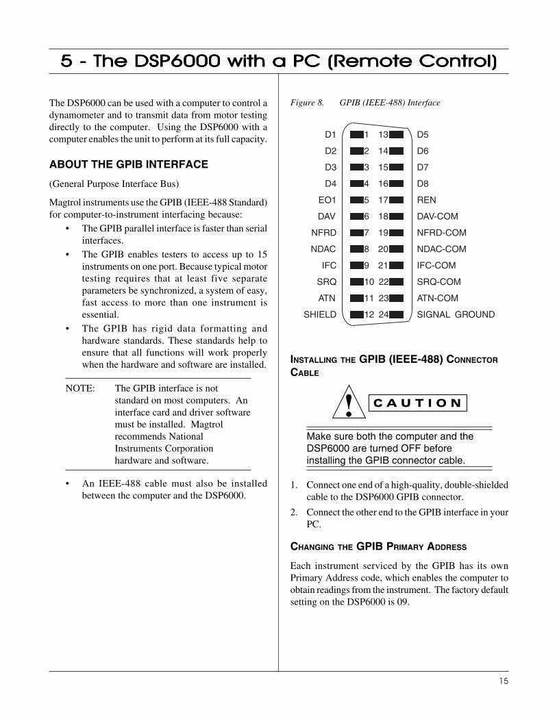
Figure 8. GPIB (IEEE-488) Interface
D5
D6
D7
D8
REN
DAV-COM
NFRD-COM
NDAC-COM
IFC-COM
SRQ-COM
ATN-COM
SIGNAL GROUND
D1
D2
D3
D4
EO1
DAV
NFRD
NDAC
IFC
SRQ
ATN
SHIELD
1 13
2 14
3 15
4 16
5 17
6 18
7 19
8 20
9 21
10 22
11 23
12 24
INSTALLING THE GPIB (IEEE-488) CONNECTOR
CABLE
Make sure both the computer and theDSP6000 are turned OFF beforeinstalling the GPIB connector cable.
1. Connect one end of a high-quality, double-shieldedcable to the DSP6000 GPIB connector.
2. Connect the other end to the GPIB interface in yourPC.
CHANGING THE GPIB PRIMARY ADDRESS
Each instrument serviced by the GPIB has its ownPrimary Address code, which enables the computer toobtain readings from the instrument. The factory defaultsetting on the DSP6000 is 09.
5 - The DSP6000 with a PC (R5 - The DSP6000 with a PC (R5 - The DSP6000 with a PC (R5 - The DSP6000 with a PC (R5 - The DSP6000 with a PC (Remote Control)emote Control)emote Control)emote Control)emote Control)
16
Magtrol Model DSP6000 Dynamometer ControllerChapter 5 - The DSP6000 with a PC (Remote Control)
Some PC interfaces can access from one to fifteen 4-bitprimary addresses. Other interfaces can access as manyas thirty-one 5-bit primary addresses. The DSP6000uses the 4-bit format.
1. Press the SHIFT button and release.
2. Press the COM SETUP button to set the primaryaddress.
3. Press the button below the GPIB address display toincrease by 1 (range 0–15).
6. Press SHIFT to input the address.
CHECKING THE DSP6000-TO-PCCONNECTION
NOTE: Make sure that the DSP6000 andits host computer arecommunicating before acquiringdata.
1. Make sure the primary address is set correctly forthe DSP6000 (see above).
2. Set the input variable to 15 characters (13 variablecharacters and the two required data terminationcharacters CR and LF. (See “Programming” laterin this chapter.)
3. Issue output data command "OD" and read 15characters according to the instructions for yourGPIB interface.
Desired results:
• Torque/speed data will be returned
• The error message I/O ERROR does not appear onthe display panel.
NOTE: If the desired results did notoccur, please see Chapter 7 -Troubleshooting.
PROGRAMMING
NOTE: Check the manual provided withyour software for fullinstructions.
1. Use the following information to answer theformatting questions asked when installing yourGPIB software.
• All GPIB data acquisition systems require theuse of data termination characters. TheDSP6000 uses the GPIB standard terminationcharacters "Carriage Return (CR)-Line Feed(LF)." Provide them in that order.
CODES FOR CR - LF
CISAB XEH CED
=RC )31($RHC D0 31
=FL )01($RHC A0 01
2. Set the timeout for at least one second if asked toset a communication fault delay timeout.
• If the communication fault delay timeout is tooshort, or if the computer resets the interface tooquickly, the host instrument may stopresponding.
DSP6000 COMMAND SET
When entering a command code:
1. Type all characters in uppercase ASCII format.
2. End all commands with a CR-LF (hex 0D-0A).
3. Do not string multiple commands together in oneline.
The character # represents a floating point numericalvalue following the command. Leading zeroes are notrequired.
NOTE: If a command is not recognized,the I/O ERROR message willappear in the Status Display.
17
Magtrol Model DSP6000 Dynamometer Controller Chapter 5 - The DSP6000 with a PC (Remote Control)
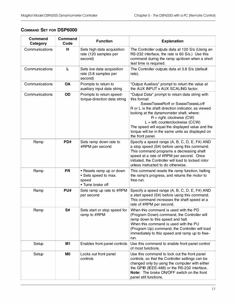
COMMAND SET FOR DSP6000
CommandCategory
CommandCode
Function Explanation
Communications H Sets high data acquisitionrate (120 samples persecond)
The Controller outputs data at 120 S/s (Using anRS-232 interface, the rate is 60 S/s.) Use thiscommand during the ramp up/down when a shorttest time is required.
Communications L Sets low data acquisitionrate (3.8 samples persecond)
The Controller outputs data at 3.8 S/s (defaultrate).
Communications OA Prompts to return toauxiliary input data string
"Output Auxiliary" prompt to return the value atthe AUX INPUT x AUX SCALING factor.
Communications OD Prompts to return speed-torque-direction data string
"Output Data" prompt to return data string withthis format:
SxxxxxTxxxxxRcrlf or SxxxxxTxxxxxLcrlfR or L is the shaft direction indicator, as viewedlooking at the dynamometer shaft, where:
R = right; clockwise (CW)L = left; counterclockwise (CCW)
The speed will equal the displayed value and thetorque will be in the same units as displayed onthe front panel.
Ramp PD# Sets ramp down rate to#RPM per second
Specify a speed range (A, B, C, D, E, F#) ANDa stop speed (S#) before using this command.This command programs a decreasing shaftspeed at a rate of #RPM per second. Onceinitiated, the Controller will load to locked rotorunless instructed to do otherwise.
Ramp PR • Resets ramp up or down• Sets speed to max.speed• Turns brake off
This command resets the ramp function, haltingthe ramp's progress, and returns the motor tofree-run.
Ramp PU# Sets ramp up rate to #RPMper second
Specify a speed range (A, B, C, D, E, F#) ANDa start speed (S#) before using this command.This command increases the shaft speed at arate of #RPM per second.
Ramp S# Sets start or stop speed forramp to #RPM
When this command is used with the PD(Program Down) command, the Controller willramp down to this speed and halt.When this command is used with the PU(Program Up) command, the Controller will loadimmediately to this speed and ramp up to free-run.
Setup M1 Enables front panel controls Use this command to enable front panel controlof most functions.
Setup M0 Locks out front panelcontrols
Use this command to lock out the front panelcontrols, so that the Controller settings can bechanged only by using the computer with eitherthe GPIB (IEEE-488) or the RS-232 interface.Note: The brake ON/OFF switch on the frontpanel still functions.
18
Magtrol Model DSP6000 Dynamometer ControllerChapter 5 - The DSP6000 with a PC (Remote Control)
CommandCategory
CommandCode Function Explanation
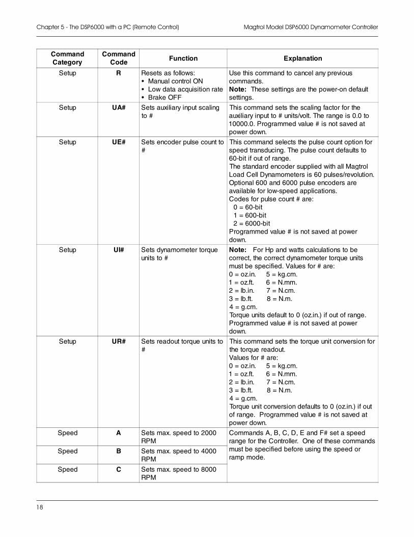
Setup R Resets as follows:• Manual control ON• Low data acquisition rate• Brake OFF
Use this command to cancel any previouscommands.Note: These settings are the power-on defaultsettings.
Setup UA# Sets auxiliary input scalingto #
This command sets the scaling factor for theauxiliary input to # units/volt. The range is 0.0 to10000.0. Programmed value # is not saved atpower down.
Setup UE# Sets encoder pulse count to#
This command selects the pulse count option forspeed transducing. The pulse count defaults to60-bit if out of range.The standard encoder supplied with all MagtrolLoad Cell Dynamometers is 60 pulses/revolution.Optional 600 and 6000 pulse encoders areavailable for low-speed applications.Codes for pulse count # are: 0 = 60-bit 1 = 600-bit 2 = 6000-bitProgrammed value # is not saved at powerdown.
Setup UI# Sets dynamometer torqueunits to #
Note: For Hp and watts calculations to becorrect, the correct dynamometer torque unitsmust be specified. Values for # are:0 = oz.in. 5 = kg.cm.1 = oz.ft. 6 = N.mm.2 = lb.in. 7 = N.cm.3 = lb.ft. 8 = N.m.4 = g.cm.Torque units default to 0 (oz.in.) if out of range.Programmed value # is not saved at powerdown.
Setup UR# Sets readout torque units to#
This command sets the torque unit conversion forthe torque readout.Values for # are:0 = oz.in. 5 = kg.cm.1 = oz.ft. 6 = N.mm.2 = lb.in. 7 = N.cm.3 = lb.ft. 8 = N.m.4 = g.cm.Torque unit conversion defaults to 0 (oz.in.) if outof range. Programmed value # is not saved atpower down.
Speed A Sets max. speed to 2000RPM
Commands A, B, C, D, E and F# set a speedrange for the Controller. One of these commandsmust be specified before using the speed orramp mode.
Speed B Sets max. speed to 4000RPM
Speed C Sets max. speed to 8000RPM
19
Magtrol Model DSP6000 Dynamometer Controller Chapter 5 - The DSP6000 with a PC (Remote Control)
CommandCategory
CommandCode Function Explanation
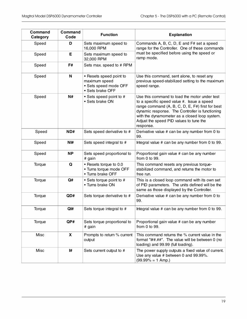
Speed D Sets maximum speed to16,000 RPM
Commands A, B, C, D, E and F# set a speedrange for the Controller. One of these commandsmust be specified before using the speed orramp mode.
Speed E Sets maximum speed to32,000 RPM
Speed F# Sets max. speed to # RPM
Speed N • Resets speed point tomaximum speed• Sets speed mode OFF• Sets brake OFF
Use this command, sent alone, to reset anyprevious speed-stabilized setting to the maximumspeed range.
Speed N# • Sets speed point to #• Sets brake ON
Use this command to load the motor under testto a specific speed value #. Issue a speedrange command (A, B, C, D, E, F#) first for bestdynamic response. The Controller is functioningwith the dynamometer as a closed loop system.Adjust the speed PID values to tune theresponse.
Speed ND# Sets speed derivative to # Derivative value # can be any number from 0 to99.
Speed NI# Sets speed integral to # Integral value # can be any number from 0 to 99.
Speed NP Sets speed proportional to# gain
Proportional gain value # can be any numberfrom 0 to 99.
Torque Q • Resets torque to 0.0• Turns torque mode OFF• Turns brake OFF
This command resets any previous torque-stabilized command, and returns the motor tofree run.
Torque Q# • Sets torque point to #• Turns brake ON
This is a closed loop command with its own setof PID parameters. The units defined will be thesame as those displayed by the Controller.
Torque QD# Sets torque derivative to # Derivative value # can be any number from 0 to99.
Torque QI# Sets torque integral to # Integral value # can be any number from 0 to 99.
Torque QP# Sets torque proportional to# gain
Proportional gain value # can be any numberfrom 0 to 99.
Misc X Prompts to return % currentoutput
This command returns the % current value in theformat "I##.##". The value will be between 0 (noloading) and 99.99 (full loading).
Misc I# Sets current output to # The power supply outputs a fixed value of current.Use any value # between 0 and 99.99%.(99.99% = 1 Amp.)
20
Magtrol Model DSP6000 Dynamometer ControllerChapter 5 - The DSP6000 with a PC (Remote Control)
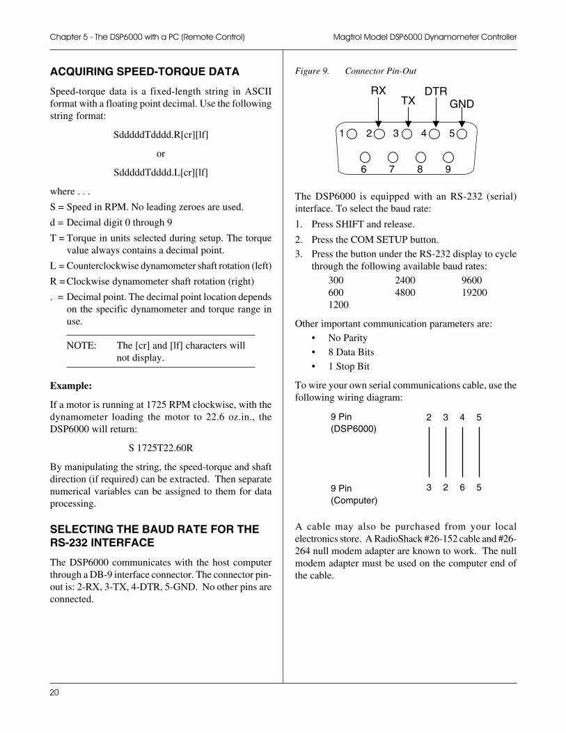
Figure 9. Connector Pin-Out
1 2 3 4 5
6 7 8 9
RXTX
DTRGND
The DSP6000 is equipped with an RS-232 (serial)interface. To select the baud rate:
1. Press SHIFT and release.
2. Press the COM SETUP button.
3. Press the button under the RS-232 display to cyclethrough the following available baud rates:
300 2400 9600600 4800 192001200
Other important communication parameters are:
• No Parity
• 8 Data Bits
• 1 Stop Bit
To wire your own serial communications cable, use thefollowing wiring diagram:
9 Pin 2 3 4 5(DSP6000)
9 Pin 3 2 6 5(Computer)
A cable may also be purchased from your localelectronics store. A RadioShack #26-152 cable and #26-264 null modem adapter are known to work. The nullmodem adapter must be used on the computer end ofthe cable.
ACQUIRING SPEED-TORQUE DATA
Speed-torque data is a fixed-length string in ASCIIformat with a floating point decimal. Use the followingstring format:
SdddddTdddd.R[cr][lf]
or
SdddddTdddd.L[cr][lf]
where . . .
S = Speed in RPM. No leading zeroes are used.
d = Decimal digit 0 through 9
T = Torque in units selected during setup. The torquevalue always contains a decimal point.
L = Counterclockwise dynamometer shaft rotation (left)
R = Clockwise dynamometer shaft rotation (right)
. = Decimal point. The decimal point location dependson the specific dynamometer and torque range inuse.
NOTE: The [cr] and [lf] characters willnot display.
Example:
If a motor is running at 1725 RPM clockwise, with thedynamometer loading the motor to 22.6 oz.in., theDSP6000 will return:
S 1725T22.60R
By manipulating the string, the speed-torque and shaftdirection (if required) can be extracted. Then separatenumerical variables can be assigned to them for dataprocessing.
SELECTING THE BAUD RATE FOR THERS-232 INTERFACE
The DSP6000 communicates with the host computerthrough a DB-9 interface connector. The connector pin-out is: 2-RX, 3-TX, 4-DTR, 5-GND. No other pins areconnected.
21
CLOSED-BOX CALIBRATION
The DSP6000 features closed-box calibration. Theadvantage of closed-box calibration is that the user doesnot have to disassemble the case or make mechanicaladjustments. However, the calibration of the AccessoryTorque Output must be done internally with Offset andGain trim pots.
The Torque readout and Auxiliary Input can becalibrated using external reference sources. Correctionfactors for Offset and Gain are stored in nonvolatilememory. They remain in effect until the user or thecalibration house updates them.
The front panel displays the actual correction factorsabove the ZERO and GAIN readouts. Record thesevalues before calibration. In the unlikely event of aController failure, it can re-initialized by pressing andholding the P, I nad D buttons while turning the poweron. All internal memory and setups will be lost. Afterre-initializing, reprogram the GAIN and ZERO valuesinto memory.
CALIBRATION SCHEDULE
Calibrate your DSP6000:
• After any repairs are performed
• At least once a year; more frequently to ensurerequired accuracy
BASIC CALIBRATION PROCESS
The basic calibration process consists of four procedureswhich must be performed in the following order:
1. Initial Procedure
2. Torque Offset and Gain
3. Accessory Torque Output Offset and Gain
4. Auxiliary Input Offset and Gain
To calibrate the DSP6000, you will need:
• External voltage reference of 0 to 5 volts DC
• Digital multimeter (DMM) with VDC accuracyof 0.05% or better
INITIAL CALIBRATION PROCEDURE
NOTE: Record the actual correctionfactors displayed beforeproceeding with calibration.
1. Allow the DSP6000 to stabilize in an environmentwith:
• An ambient temperature of 18°C to 25°C
• Relative humidity less than 80%
2. Turn on the DSP6000.
3. Allow the DSP6000 to warm up for at least 30minutes.
4. Enable the calibration mode as follows:
• Turn instrument power OFF
• Press in and hold the UP ! and DOWN "arrow buttons simultaneously
• Turn instrument power ON
5. Continue pressing the UP ! and DOWN" arrow buttons until the display shows thesoftware revision date.
6. Press the SHIFT button once.
NOTE: To exit CALIBRATE modewithout making any changes,press the SHIFT button six times.
TORQUE OFFSET AND GAIN
1. Connect the external voltage reference common toPin 13 of the dynamometer input connector.
2. Connect the external voltage reference high to Pin14 of the dynamometer input connector.
3. Apply +2.000 VDC.
4. Press the GAIN button.
5. Adjust the gain by turning the Decrease/IncreaseDial until the displayed voltage equals the referencevoltage.
6 - Calibration6 - Calibration6 - Calibration6 - Calibration6 - Calibration
22
Magtrol Model DSP6000 Dynamometer ControllerChapter 6 - Calibration
NOTE: The magnitude of change perrevolution can be increased bypressing the UP ! button ordecreased by pressing theDOWN " button.
6. Apply 0.000 VDC.
7. Press the ZERO button.
8. Adjust the Decrease/Increase Dial until the displayindicates 0 mVDC.
9. Repeat steps 3 through 8 to complete this procedure.
10. Record the correction factors displayed above theZERO and GAIN readouts for future reference.
ACCESSORY TORQUE OFFSET AND GAIN
1. Connect the DMM common to Pin 4 of theAccessory Torque-Speed Output connector.
2. Connect the DMM high to Pin 2 of the AccessoryTorque-Speed Output connector
3. Apply 0.000 VDC
4. Adjust R24 (OFFSET) on the circuit board for 0mVDC on the DMM.
5. Apply +2.000 VDC.
6. Adjust R25 (GAIN) on the circuit board for +2.000VDC on the DMM.
AUXILIARY INPUT OFFSET AND GAIN
1. Press the SHIFT button once. Display indicatesAUX INPUT calibration.
2. Connect the external voltage reference to theAuxiliary Input BNC connector.
3. Apply +5.000 VDC.
4. Press the GAIN button.
5. Adjust the gain by turning the Decrease/IncreaseDial until the displayed voltage equals the referencevoltage.
NOTE: The magnitude of change perrevolution can be increased bypressing the UP ! button ordecreased by pressing theDOWN " button.
6. Apply 0.000 VDC.
7. Press the ZERO button.
8. Adjust the Decrease/Increase Dial until the displayindicates 0 mVDC.
9. Repeat steps 3 through 8 to complete this procedure.
10. Record the correction factors above the ZERO andGAIN readouts for future reference.
11. Press the SHIFT button once to return to defaultdisplay.
ALTERNATE CALIBRATION PROCEDURE
The DSP6000 can also be calibrated by using a certifieddynamometer, calibration beam, and weight instead ofan external voltage reference.
NOTE: Magtrol suggests you do NOTuse this method. By using thealternate calibration procedure,you are calibrating the DSP6000to a specific dynamometer, not toa reference standard. If youconnect the DSP6000 to adifferent dynamometer, theresulting torque reading may beincorrect.
1. Connect the chosen dynamometer to the DSP6000using the 14-pin signal cable and the 2-pin brakecable.
2. Attach the calibration beam to the dynamometershaft.
3. Enter the calibration mode.
4. Press the BRAKE ON/OFF button ON to apply fullloading to the dynamometer.
5. Hang the weight on the calibration beam pin andlevel the beam.
6. Press the GAIN button.
7. Adjust the gain by turning the Decrease/IncreaseDial until the displayed voltage equals the referencevoltage.
NOTE: The magnitude of change perrevolution can be increased bypressing the UP ! button ordecreased by pressing theDOWN " button.
23
Magtrol Model DSP6000 Dynamometer Controller Chapter 6 - Calibration
8. Remove the weight for ZERO adjustment.
9. Press the ZERO button.
10. Adjust the Increase/Decrease Dial until the displayindicates 0 mVDC.
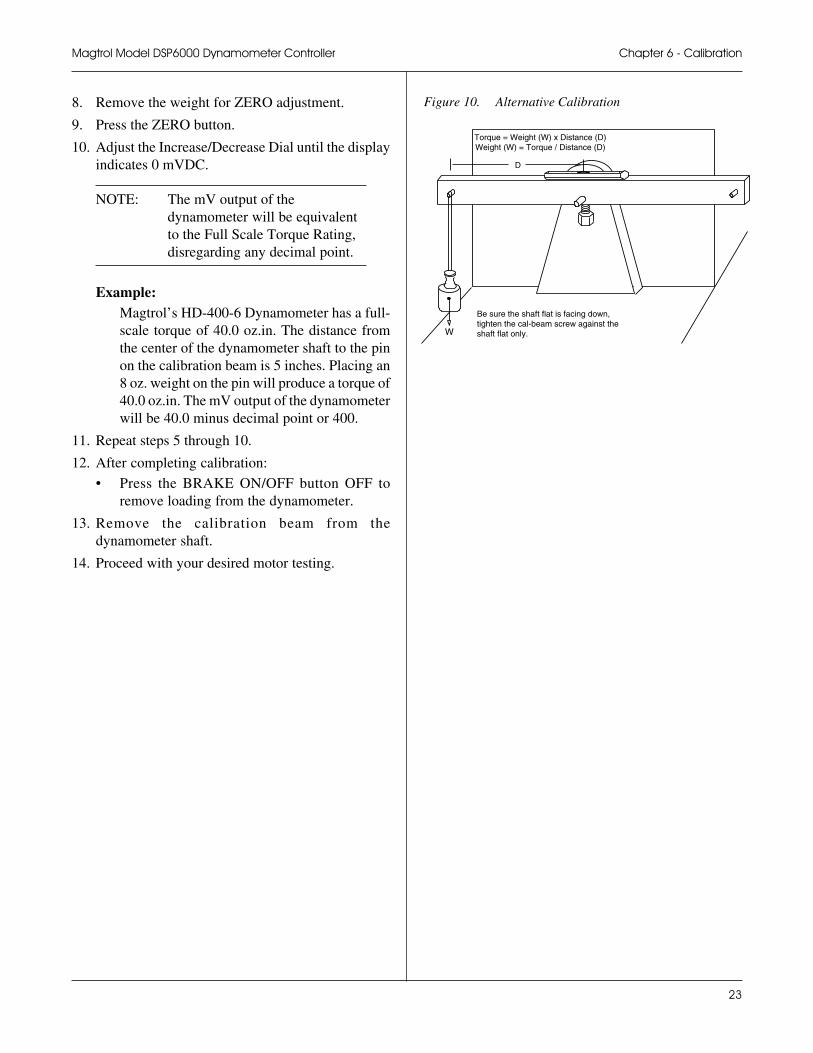
NOTE: The mV output of thedynamometer will be equivalentto the Full Scale Torque Rating,disregarding any decimal point.
Example:Magtrol’s HD-400-6 Dynamometer has a full-scale torque of 40.0 oz.in. The distance fromthe center of the dynamometer shaft to the pinon the calibration beam is 5 inches. Placing an8 oz. weight on the pin will produce a torque of40.0 oz.in. The mV output of the dynamometerwill be 40.0 minus decimal point or 400.
11. Repeat steps 5 through 10.
12. After completing calibration:
• Press the BRAKE ON/OFF button OFF toremove loading from the dynamometer.
13. Remove the calibration beam from thedynamometer shaft.
14. Proceed with your desired motor testing.
Be sure the shaft flat is facing down,tighten the cal-beam screw against theshaft flat only.
Torque = Weight (W) x Distance (D)Weight (W) = Torque / Distance (D)
D
W
Figure 10. Alternative Calibration
24
7 - T7 - T7 - T7 - T7 - Troubleshootingroubleshootingroubleshootingroubleshootingroubleshooting
If you require additional assistance, please contactMagtrol Customer Service at 1-800-828-7844 or 1-716-668-5555
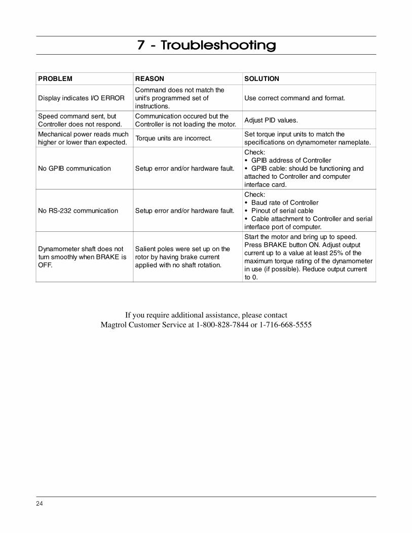
PROBLEM REASON SOLUTION
Display indicates I/O ERRORCommand does not match theunit's programmed set ofinstructions.
Use correct command and format.
Speed command sent, butController does not respond.
Communication occured but theController is not loading the motor.
Adjust PID values.
Mechanical power reads muchhigher or lower than expected.
Torque units are incorrect.Set torque input units to match thespecifications on dynamometer nameplate.
No GPIB communication Setup error and/or hardware fault.
Check:• GPIB address of Controller• GPIB cable: should be functioning andattached to Controller and computerinterface card.
No RS-232 communication Setup error and/or hardware fault.
Check:• Baud rate of Controller• Pinout of serial cable• Cable attachment to Controller and serialinterface port of computer.
Dynamometer shaft does notturn smoothly when BRAKE isOFF.
Salient poles were set up on therotor by having brake currentapplied with no shaft rotation.
Start the motor and bring up to speed.Press BRAKE button ON. Adjust outputcurrent up to a value at least 25% of themaximum torque rating of the dynamometerin use (if possible). Reduce output currentto 0.
25
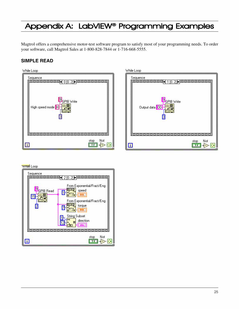
Appendix AAppendix AAppendix AAppendix AAppendix A: L: L: L: L: LabVIEWabVIEWabVIEWabVIEWabVIEW®®®®® P P P P Programming Examplesrogramming Examplesrogramming Examplesrogramming Examplesrogramming Examples
SIMPLE READ
Magtrol offers a comprehensive motor-test software program to satisfy most of your programming needs. To orderyour software, call Magtrol Sales at 1-800-828-7844 or 1-716-668-5555.
26
Magtrol Model DSP6000 Dynamometer ControllerAppendix A: LabVIEW Programming Examples
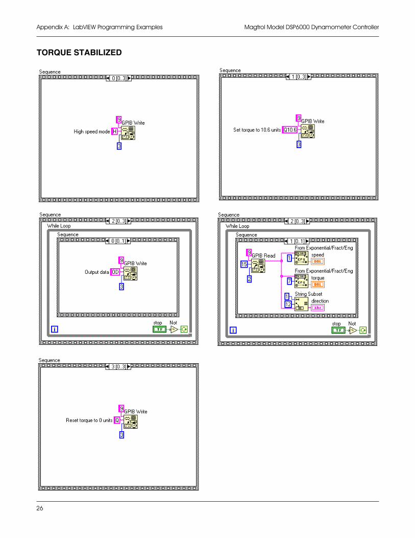
TORQUE STABILIZED
27
Magtrol Model DSP6000 Dynamometer Controller Appendix A: LabVIEW Programming Examples
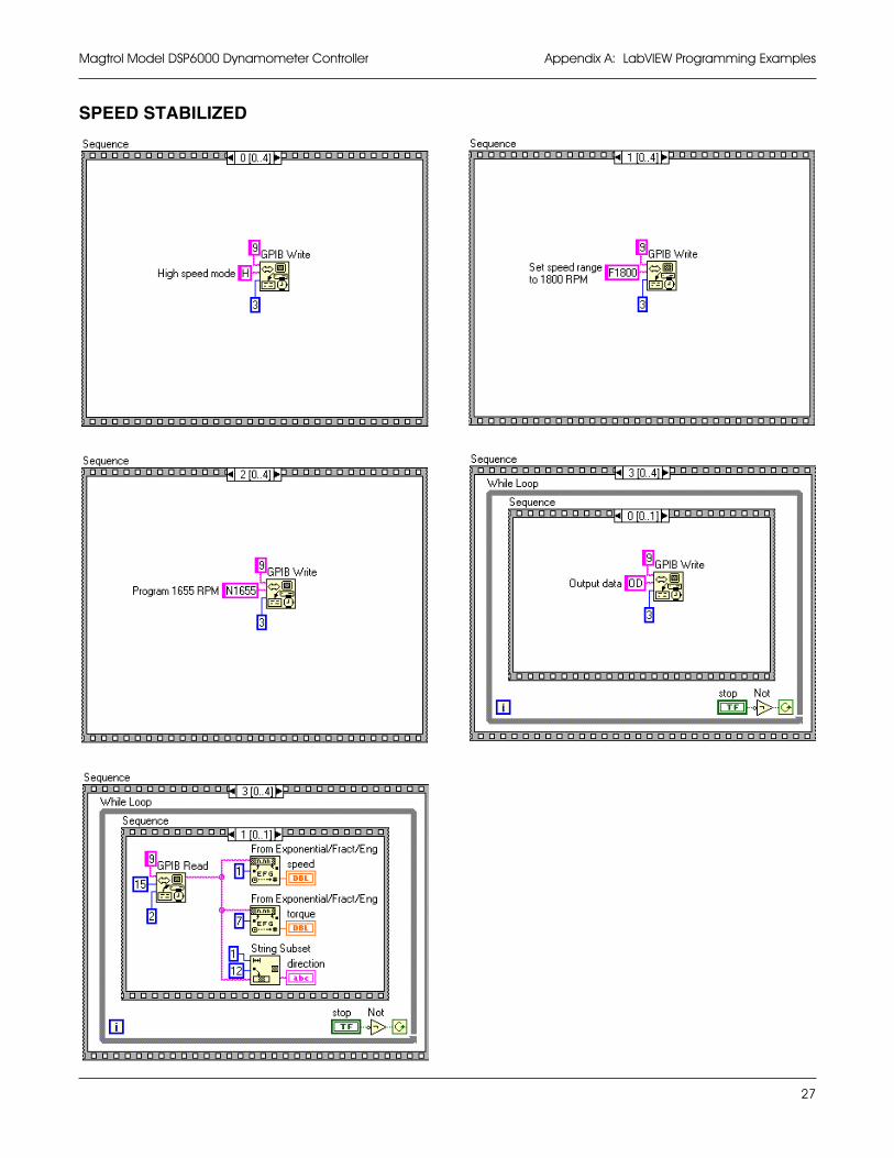
SPEED STABILIZED
28
INERTIAL EFFECT ON MOTOR TESTDATA
A major advantage of the DSP6000 is its ability to obtainfull motor performance data (free run to locked rotor)by continuous load application with an absorptiondynamometer. Data acquisition is fast, resulting inminimal motor I2R losses, and loading characteristicssimulate actual end-use applications.
When a motor is accelerating or decelerating, themeasured torque is the sum of the true motor torque ±the inertial torque, or stored energy, of the system.Unless inertial torque is excluded, motor performancewill vary in proportion to the rate of acceleration ordeceleration.
This type of error can produce problematic test results.For example, during rapid deceleration, system inertiacan produce apparent efficiency greater than 1.0. Thiserror may occur if output power is divided by inputpower without extracting the stored energy in thesystem.
Since "inertial effect" is only a factor when speed ischanging, and because inertial torque is proportional tothe rate of change, inertial value may be expressed as aunit of torque per change in RPM in a given period oftime. With the DSP6000, properly adjusted PID valuesyield constant change in RPM so that the inertial torquecan be expressed as a constant.
PROCEDURE FOR INERTIACORRECTION1. Determine the torque Correction Factor (CF) as
follows:
• Adjust the PID loop properly
• Establish a torque value equal to the inertialtorque.
2. Use the "Program Down" command (PD#) to rampto 75% of the free-run speed.
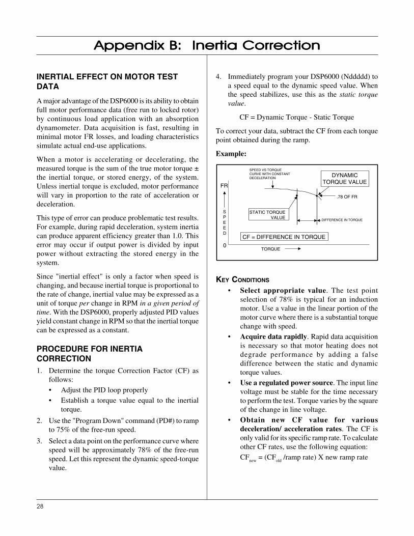
3. Select a data point on the performance curve wherespeed will be approximately 78% of the free-runspeed. Let this represent the dynamic speed-torquevalue.
Appendix BAppendix BAppendix BAppendix BAppendix B: Inertia Correction: Inertia Correction: Inertia Correction: Inertia Correction: Inertia Correction
4. Immediately program your DSP6000 (Nddddd) toa speed equal to the dynamic speed value. Whenthe speed stabilizes, use this as the static torquevalue.
CF = Dynamic Torque - Static Torque
To correct your data, subtract the CF from each torquepoint obtained during the ramp.
Example:
FR
0TORQUE
DYNAMICTORQUE VALUE
SPEED VS TORQUECURVE WITH CONSTANTDECELERATION
.78 OF FR
STATIC TORQUEVALUE
CF = DIFFERENCE IN TORQUE
SPEED
DIFFERENCE IN TORQUE
KEY CONDITIONS
• Select appropriate value. The test pointselection of 78% is typical for an inductionmotor. Use a value in the linear portion of themotor curve where there is a substantial torquechange with speed.
• Acquire data rapidly. Rapid data acquisitionis necessary so that motor heating does notdegrade performance by adding a falsedifference between the static and dynamictorque values.
• Use a regulated power source. The input linevoltage must be stable for the time necessaryto perform the test. Torque varies by the squareof the change in line voltage.
• Obtain new CF value for variousdeceleration/ acceleration rates. The CF isonly valid for its specific ramp rate. To calculateother CF rates, use the following equation:
CFnew
= (CFold
/ramp rate) X new ramp rate
29
Appendix CAppendix CAppendix CAppendix CAppendix C: F: F: F: F: Front Pront Pront Pront Pront Panel/Display Menu Flow Chartsanel/Display Menu Flow Chartsanel/Display Menu Flow Chartsanel/Display Menu Flow Chartsanel/Display Menu Flow Charts
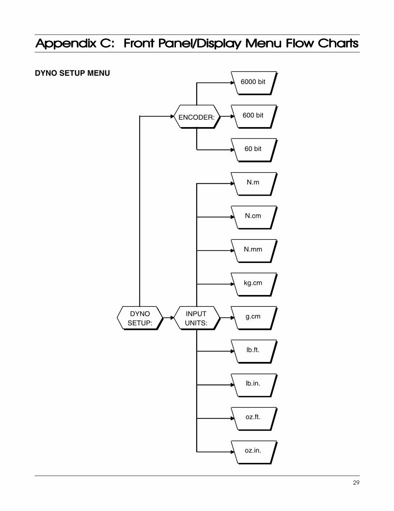
DYNO SETUP MENU
DYNOSETUP:
INPUTUNITS:
oz.in.
oz.ft.
lb.in.
lb.ft.
g.cm
kg.cm
N.mm
N.cm
N.m
ENCODER:
60 bit
600 bit
6000 bit
30
Magtrol Model DSP6000 Dynamometer ControllerAppendix C: Front Panel/Display Menu Flow Charts
COM SETUP MENU
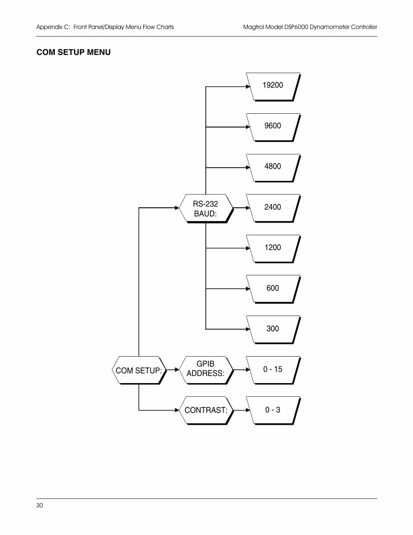
COM SETUP:
CONTRAST: 0 - 3
GPIBADDRESS: 0 - 15
RS-232BAUD:
300
600
1200
2400
4800
9600
19200
31
Magtrol Model DSP6000 Dynamometer Controller Appendix C: Front Panel/Display Menu Flow Charts
AUX SETUP MENU
POWER UNITS MENU
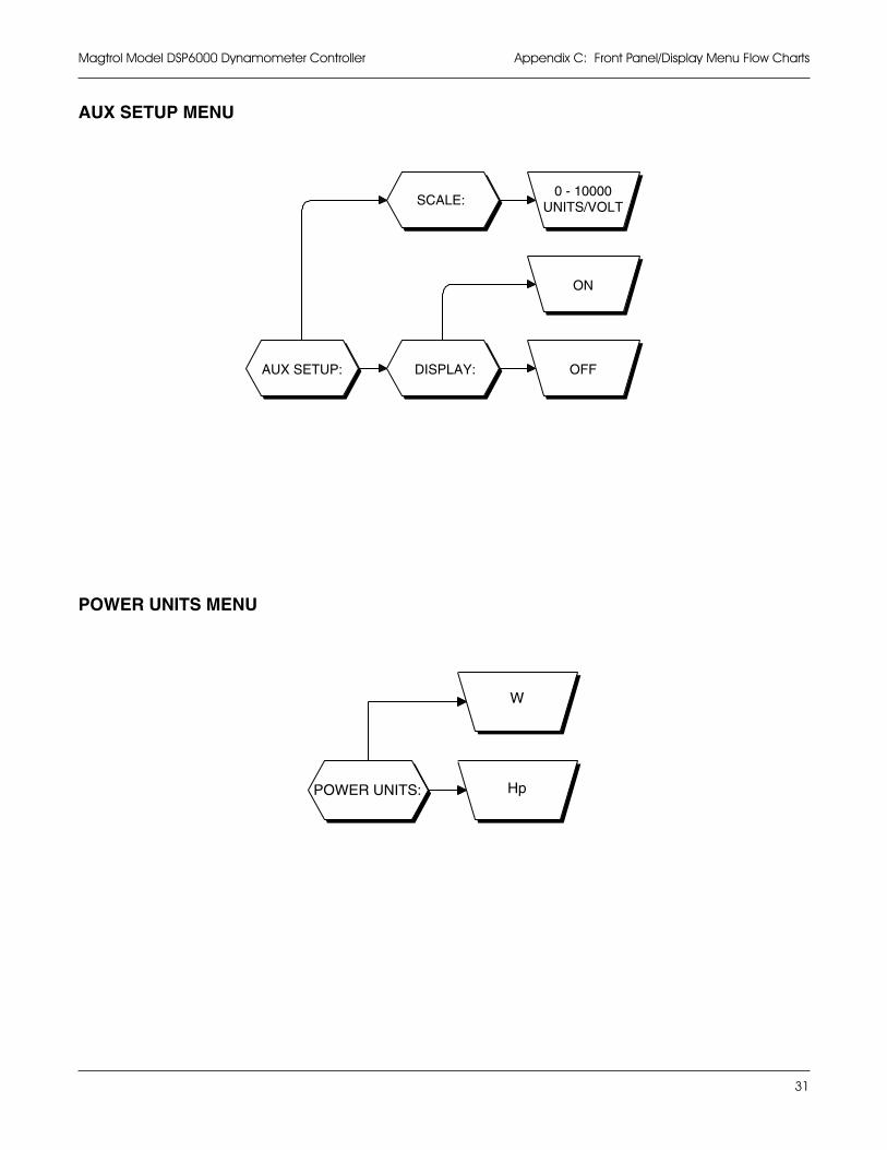
AUX SETUP: DISPLAY: OFF
ON
SCALE:0 - 10000
UNITS/VOLT
Hp
W
POWER UNITS:
32
Magtrol Model DSP6000 Dynamometer ControllerAppendix C: Front Panel/Display Menu Flow Charts
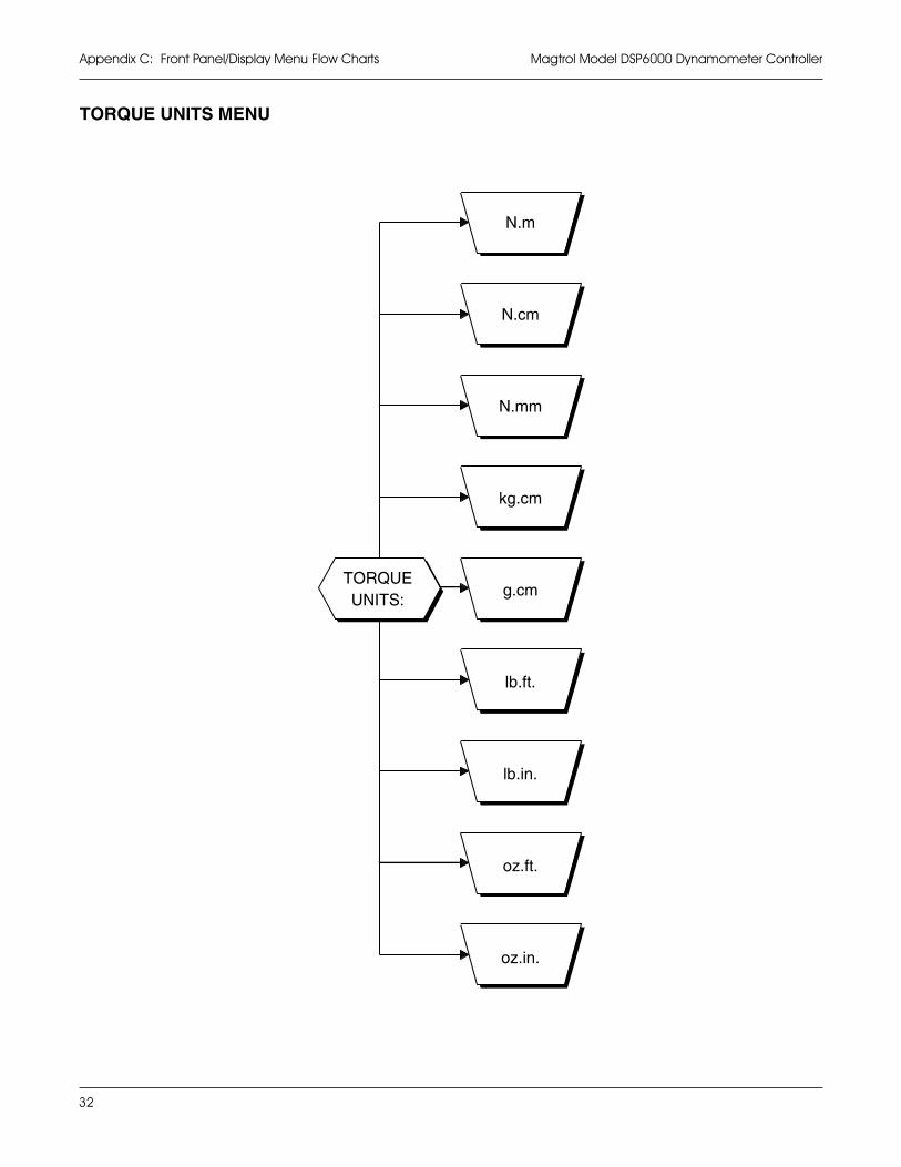
oz.in.
oz.ft.
lb.in.
lb.ft.
g.cm
kg.cm
N.mm
N.cm
N.m
TORQUEUNITS:
TORQUE UNITS MENU
33
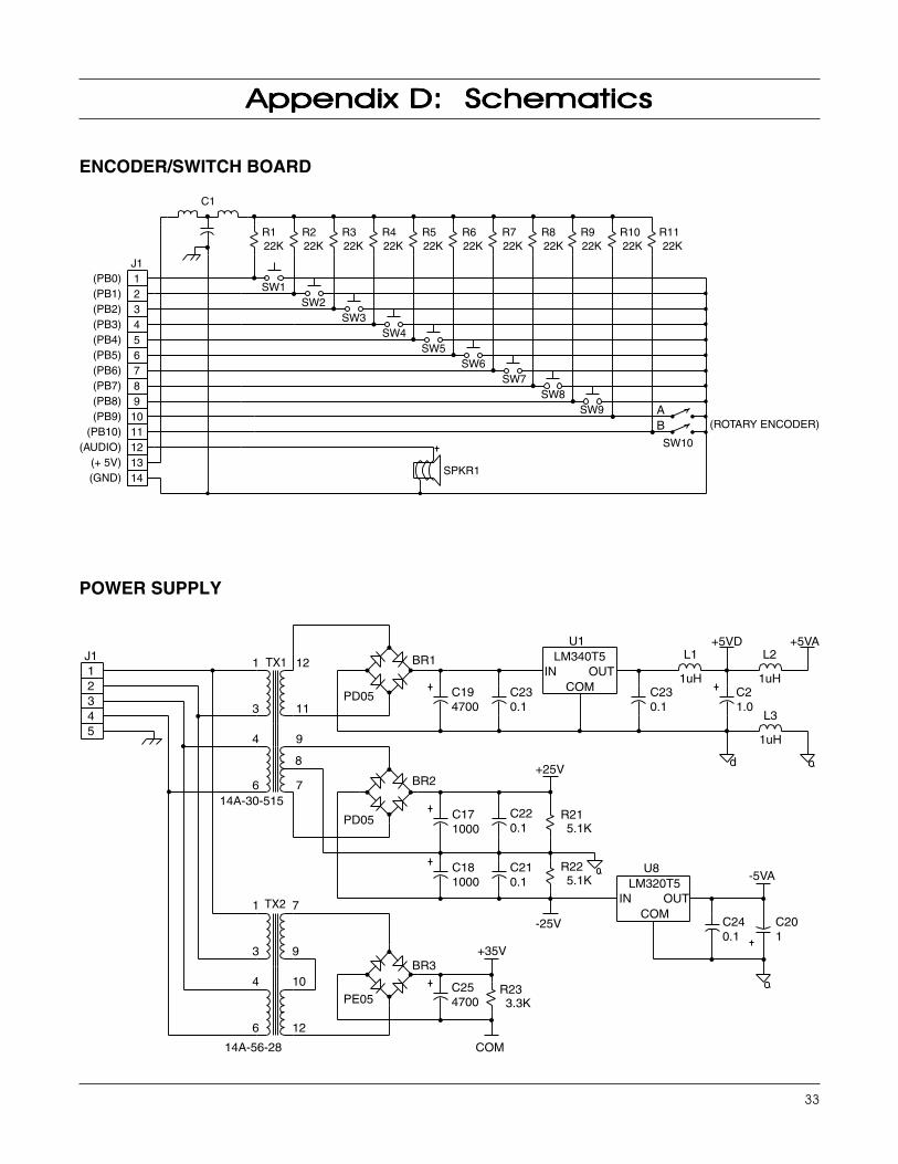
Appendix DAppendix DAppendix DAppendix DAppendix D: Schematics: Schematics: Schematics: Schematics: Schematics
POWER SUPPLY
ENCODER/SWITCH BOARD
(ROTARY ENCODER)
SPKR1
(PB0)(PB1)(PB2)(PB3)(PB4)(PB5)(PB6)(PB7)(PB8)(PB9)
(PB10)(AUDIO)
(+ 5V)(GND)
J11234567891011121314
R7R6R5R4R3R2R1 R8 R9 R10 R11
C1
22K 22K 22K 22K 22K 22K 22K 22K 22K 22K 22K
SW10
SW9SW8
SW7SW6
SW5SW4
SW3SW2
SW1
AB
BR1
BR2
BR3
PD05
PD05
PE05
C194700
C254700
C230.1
C220.1
C210.1
C181000
C171000
C230.1
C21.0
C201
C240.1
U1LM340T5
IN OUTCOM
U8LM320T5
IN OUTCOM
COM
+25V
+35V
-25V
L3
1uH
L2
1uH
L1
1uH
+5VD +5VA
-5VA
d
R21
R22
5.1K
5.1K
R233.3K
14A-56-28
14A-30-515
1
3
4
6
7
9
10
12
1
3
4
6
12
11
9
7
8
TX1
TX2
J112345
34
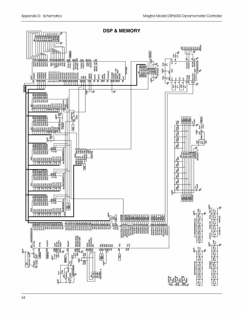
Magtrol Model DSP6000 Dynamometer ControllerAppendix D: Schematics
DSP & MEMORYU
12
U1
0U
11
U7
I/O
3I/
O2
I/O
4A
5
13
14
I/O
0I/
O1
10
9 11
4 3
A2
5A
3A
4
8A
0A
167
A1
0
A7
AT
28C
16E
-20S
CC
E
I/O
7A
8A
9
OE
WE
I/O
5A
6I/
O6
16
15
17
21
19
18
202 1
23
22
R2
02
2K
R4
32
2K
U2
0a
37
4H
C0
01 2
U1
9
Y2
Y3
13
12
15
14
3 6
Y1
B G1
C
1A
Y0
2
74
HC
13
8
9 711
10
G2B
5
Y6
Y5
Y7
4Y
4G
2A
DS
~
PA
GE
J8
16
18
17
13
15
14
4 651 32
IEE
E4
88
23
24
20
19
22
21
10
12
11
7 8 9
U6
O4
O6
O5
17
16
18
O2
O1
O3
13
12
11
15
6 4
A4
A3
7
A5
59 8
10
A2
A1
A0
A1
0A
11
A1
3
CE
A1
2
A1
4
MB
M2
7C
51
2
OE
/VP
PA
15
A6
A7
A9
A8
19
O7
O8
27
262
22
201
253
23
24
21
U1
3
79
70
ND
AC
IFC
RE
N
SR
Q
85
73
AT
NE
OI
NR
FD
DA
V
82
81
9576
84
DIO
6
DIO
8D
IO7
DIO
3
92
DIO
5
DIO
2D
IO1
DIO
4
80
77
74
71
91
89
88
6 7 95 49
47
50
10
11
DA
TA
10
DA
TA
12
DA
TA
13
DA
TA
11
DA
TA
7D
AT
A6
DA
TA
9D
AT
A8
67
17
16
18
19
3215
AD
DR
3
RE
SE
T
AD
DR
4
DA
TA
14
AD
DR
2
DA
TA
15
AD
DR
0A
DD
R1
CP
UA
CCA
BU
S_
OE
BB
US
_O
E
DA
CK
BB
US
AB
US T
NT
48
82
BU
RS
T_
RD
FIF
O_
RD
YM
OD
E
PA
GE
D
23
28
TR
IGR
EM
20
51
1
DC
AS
KE
YC
LK
XT
AL
1X
TA
L0
DA
TA
2D
AT
A3
DA
TA
5D
AT
A4
LA
DC
S
KE
YR
ST
KE
YD
QD
AT
A0
TA
DC
S
DA
TA
19
99
8
96
66
10
0
21
26
32
33
22
38
53
29
52
30
31
RD
Y1
DR
Q
INT
R
NC
SW
AP
55
43
44
39
42
46
64
62
34
14
63
RD
WR
CS
40
MH
z
dd
RE
SE
T~
D3
D2
D1
D0
D6
D4
D5
D1
9D
22
D2
1D
23
13
15
11
12
D1
6D
20
D1
8D
17
19
18
17
16
+5
VD
U4 M
OD
C/IR
QB
NM
I
EX
TA
L
MO
DB
/
CK
OU
T IRQ
AM
OD
A/
PIN
IT
RE
SE
T
PC
AP
PL
OC
K
XT
AL
CK
P
WR
nc
1
TIO
nc
2
DS
CK
/OS
1
DS
OD
SI/
OS
0
WT
BG
BR
BS
RD
DR
BN
11
4
60
11
8
D2
2D
23
10
31
04
D9
96
11
11
09
11
71
15
11
2
10
61
07
10
8
10
01
01
74
A6
A8
A9
64
65
A2
A5
68
77
82
78
80
83
63
72
76
61
71
73
11
9
12
11
20
53
D1
2
51
50
52
D1
6D
17
D2
0
D1
8D
19
D2
1
D1
3
D1
5D
14
D1
0D
11
DS
P5
60
02
FC
40
12
3
13
21
12
5
12
81
30
13
1
12
6
A1
2
A1
5
A1
1
A1
3A
14
A3
A4
A7
A1
A0
A1
0
23
14
17
15
7 26
33
25
SC
LK
/PC
2
38
24
21
19
18
35
32
28
29
3193
94
D8
D7
95
12
10
6
D6
485
88
87
90
91
5584
57
13
859
HA
0/P
B8
HA
1/P
B9
HA
2/P
B1
04
9H
R/W
/PB
11
SC
K/P
C6
SR
D/P
C7
SC
0/P
C3
RX
D/P
C0
SC
1/P
C4
H5
/PB
5H
6/P
B6
H3
/PB
3H
4/P
B4
H7
/PB
7
SC
2/P
C5
ST
D/P
C8
H2
/PB
2
TX
D/P
C1
H1
/PB
1H
0/P
B0
42
47
44
41
46
HR
EQ
/PB
13
43
40
54
39
D2
D3
D1
D5
D4
X/Y
DS
PS
HA
CK
/PB
14
HE
N/P
B1
2
D0
C1
0
0.0
12
R1
7
2.2
KU
3
INP
UT
2
MC
3406
4D1
4GN
DR
ES
RE
SE
T~
R1
9
22
K
C8
10
.1C
60
.01
25 5 242 431 26 7236 21 9 108
244 52 26
2531 96 7 21
10
23 8
25 5 242 431 26 7236 21 9 108
RD
~W
R~
U5
8V
DD
1
OU
T5
GN
D
XT
AL
_O
SC
4
NC
/OE
+5
VD
d
40
MH
z
D8
D14
D15
D13
13
15
11
12
D12
D11
D10
D9
19
18
17
16
D5
D7
D1
D3
13
15
12
11
D2
D0
D6
D4
17
18
19
16
J2
4 6 82
531
HE
AD
ER
_1
4K
EY
PA
D1
41
21
01
11
3
97
R1 22
KR
10
22
KR
9 22
KR
4 22
KR
5 22
KR
6 22
KR
2 22
KR
3 22
K
C7
9
1.0
R1
4
33
0
Q1
MM
BT2
222
C1
0.0
01
d
d
U2
1
V-
C2-
6 14
16 V
CC
2V
+
4 11
5
C2+
1 3
C1+
C1-
GN
D MA
X23
2CS
E
8R
X1I
NR
X2I
N
TX
1OU
TT
X2O
UT
7 13
RX
1OU
T9
RX
2OU
T 15
12
10
TX
1IN
TX
2IN
C6
8
0.1
J1
0
4 521 3
RS
23
2
8 96 7
C7
7
0.1
C5
3
0.1
d
PB
7P
B5
R1
12
2K
R1
32
2K
R1
22
2K
PB
3P
B1
d
d
d+
5V
D
R1
6
3.3
K
dd
PB
11
C7
0.0
01
PB
9
d
+5
VD
DS
~
d
J4
862 43 751
HE
AD
ER
_1
6D
ISP
LA
Y1
61
4
10
12
11
13
15
9
C7
6
0.1d
BU
SY
+5
VD
d
C6
9
0.1
+5
VD
d
+5
VD
+5
VD
C1
40
.1C
50
.1
+5
VD
C1
50
.01
d
C4
0.0
1C
80
.1C
12
0.0
1C
90
.01
DS
P5
60
02
FC
40
+5
VD
C3
20
.01
C2
90
.01
d
C3
80
.1C
39
0.1
C3
00
.01
C3
50
.1
3 x
MC
M6
20
6B
AE
J2
5
U2
0d1
47
4H
C0
012 13 d
U2
0b6
74
HC
00
4 5
U2
0c8
74
HC
00
9 10
d
C4
50
.1C
37
0.1
C5
80
.1C
11
0.1
C4
80
.1C
75
0.1
C7
40
.1C
36
0.1
C7
30
.1
PB
2P
B0
PB
6P
B4
PB
8
PB
1P
B0
DP
AD
PB
+5
VD
FS
IL
/R
ST
DS
RD
SC
K
C1
30
.1C
72
0.1
d
PB
10
+5
VD
C1
60
.1C
71
0.1
dR
15
22
K
J3
4231
HE
AD
ER
_8
8675
R1
82
2K
TIO
RD
~W
R~
PB
8P
B9
PB
5P
B4
PB
6P
B7
PB
2P
B3
PA
GE
DS
~
BU
SY
PB
10
R7
2
22
K
PB
11
+5
VD
WG2
72
22
0
MC
M6
20
6B
AE
J2
5
D1
D2
D0
DQ
2
D6
D7
D3
D5
D4
D7
DQ
3
d
+5
VD
+5
VD
d
A1
3
WA
11
A1
2A
11
27
A1
2W
A1
22
7
A1
2
MC
M6
20
6B
AE
J2
5M
CM
6206
BA
EJ2
5
A1
4A
13
A1
4A
13
A1
4
A1
5
A0
A1
A3
DQ
1A
2D
Q2
DQ
32
MH
z
A8
A7
A9
A1
0A
11
A5
DQ
5A
4
DQ
7A
6
+5
VD
A3
A4
DQ
4
A2
DQ
5A
5
DQ
0A
0D
Q1
A1
A4
DQ
4D
Q3
DQ
4A
3
DQ
5A
5
A0
A2
DQ
0D
Q0
A1
DQ
2D
Q1
22
GE
A9
A1
0
A6
DQ
6
20
DQ
7D
Q6
DQ
7A
7A
8
22
GE
A1
02
0
DQ
6 E
A6
A7
A8
A9
+
A1
4A
15
A1
3
D2
D0
D6
D4
D3
D5
D1
D7
TN
T4
88
22
7C
51
2
74
HC
00
XT
AL
_OS
C
AT
28
C1
6
74
HC
13
8
+5
VD
+5
VD
+5
VD
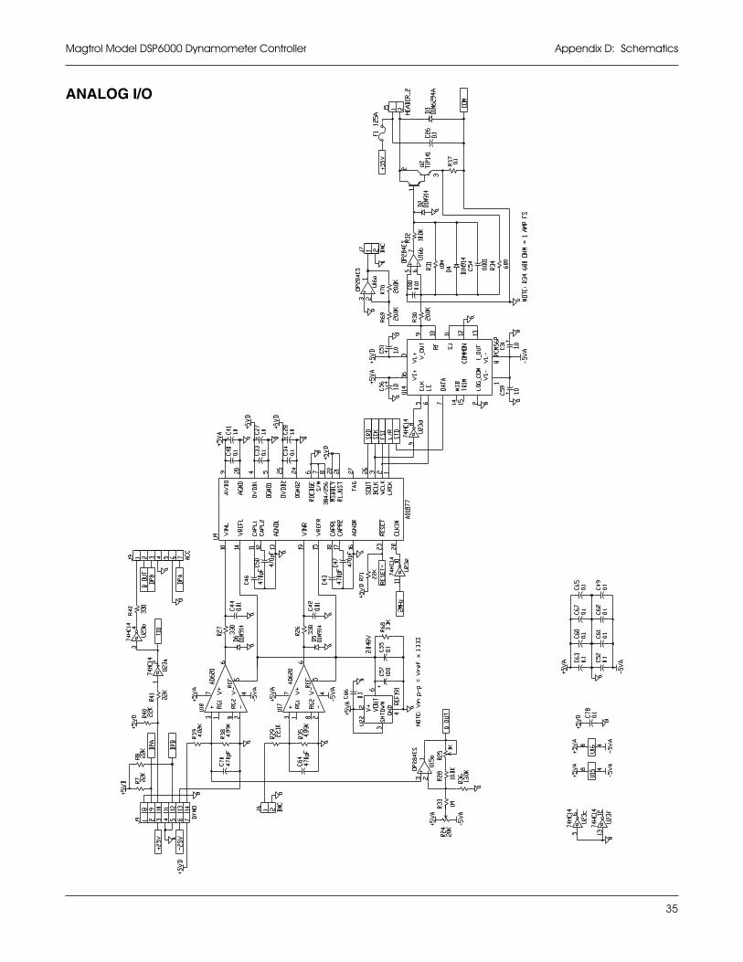
35
Magtrol Model DSP6000 Dynamometer Controller Appendix D: Schematics
ANALOG I/O
36
GlossarGlossarGlossarGlossarGlossary of Abbreviations and Ty of Abbreviations and Ty of Abbreviations and Ty of Abbreviations and Ty of Abbreviations and Termsermsermsermserms
BNC ............................................................................. bayonet, locking-type connector
CCW ............................................................................ counterclockwise (turn to left)
CF ................................................................................ correction factor (inertia correction factor)
CR ................................................................................ carriage return
CW ............................................................................... clockwise (turn to right)
D .................................................................................. derivative
D/A .............................................................................. digital to analog converter
DMM ........................................................................... digital multimeter
FR ................................................................................ free-run speed
GPIB (General Purpose Interface Bus) ....................... parallel interface port; interchangeable with IEEE-488
Hp ................................................................................ horsepower; measure of mechanical power
Hz ................................................................................ hertz; frequency
I .................................................................................... integral
I/O ................................................................................ input/output
LF ................................................................................ line feed
local ............................................................................. manual control (use front panel controls)
mVDC.......................................................................... millivolts DC
N .................................................................................. speed
NEMA ......................................................................... National Electrical Manufacturers Association
P ................................................................................... proportional; proportional gain
PID ............................................................................... proportional, integral, derivative
PMDC .......................................................................... permanent magnet DC
Q .................................................................................. torque
remote .......................................................................... computer control (uses programmed controls from computer)
RPM ............................................................................. revolutions per minute
SI .................................................................................. Systeme Internationale units of measure
S/s ................................................................................ samples per second
V .................................................................................. volts; typically AC
VDC ............................................................................. volts DC

Magtrol, Inc. warrants its products to be free from defects in material and workmanship under normal use andservice for a period of one (1) year from the date of shipment. Software is warranted to operate in accordance withits programmed instructions on appropriate Magtrol instruments. This warranty extends only to the original purchaserand shall not apply to fuses, computer media, or any other product which, in Magtrol’s sole opinion, has beensubject to misuse, alteration, abuse or abnormal conditions of operation or shipping.
Magtrol’s obligation under this warranty is limited to repair or replacement of a product which is returned to thefactory within the warranty period and is determined, upon examination by Magtrol, to be defective. If Magtroldetermines that the defect or malfunction has been caused by misuse, alteration, abuse or abnormal conditions ofoperation or shipping, Magtrol will repair the product and bill the purchaser for the reasonable cost of repair. If theproduct is not covered by this warranty, Magtrol will, if requested by purchaser, submit an estimate of the repaircosts before work is started.
To obtain repair service under this warranty, purchaser must forward the product (transportation prepaid) and adescription of the malfunction to the factory. The instrument shall be repaired at the factory and returned to purchaser,transportation prepaid. MAGTROL ASSUMES NO RISK FOR IN-TRANSIT DAMAGE.
THE FOREGOING WARRANTY IS PURCHASER’S SOLE AND EXCLUSIVE REMEDY AND IS IN LIEU OFALL OTHER WARRANTIES, EXPRESSED OR IMPLIED, INCLUDING BUT NOT LIMITED TO ANY IMPLIEDWARRANTY OF MERCHANTABILITY, OR FITNESS FOR ANY PARTICULAR PURPOSE OR USE.MAGTROL SHALL NOT BE LIABLE FOR ANY SPECIAL, INDIRECT, INCIDENTAL, OR CONSEQUENTIALDAMAGES OR LOSS WHETHER IN CONTRACT, TORT, OR OTHERWISE.
CLAIMSImmediately upon arrival, purchaser shall check the packing container against the enclosed packing list and shall,within thirty (30) days of arrival, give Magtrol notice of shortages or any nonconformity with the terms of the order.If purchaser fails to give notice, the delivery shall be deemed to conform with the terms of the order.
The purchaser assumes all risk of loss or damage to products upon delivery by Magtrol to the carrier. If a product isdamaged in transit, PURCHASER MUST FILE ALL CLAIMS FOR DAMAGE WITH THE CARRIER to obtaincompensation. Upon request by purchaser, Magtrol will submit an estimate of the cost to repair shipment damage.
Magtrol Limited WMagtrol Limited WMagtrol Limited WMagtrol Limited WMagtrol Limited Warrantyarrantyarrantyarrantyarranty

MOTOR TESTING EQUIPMENT ! HYSTERESIS BRAKES AND CLUTCHES
70 Gardenville Parkway ! Buffalo, New York 14224Phone: (716) 668-5555 ! (800) 828-7844 Fax: (716) 668-8705Web site: www.magtrol.com ! E-mail: [email protected]