Embed Size (px)
Citation preview
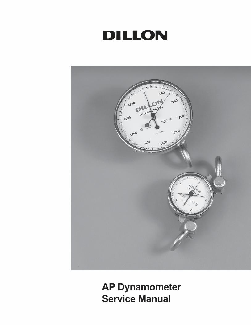
AP Dynamometer
Service Manual

2 AP Dynamometer Service Manual
3AP Dynamometer Service Manual
AP Dynamometer Introduction .............................................................................................................................. 5
The Dillon Mechanical Dynamometer Family .................................................................................................. 5
About This Manual .......................................................................................................................................... 5
Disassembly and Reassembly .............................................................................................................................. 6
Separation of Pressure Bar and Gauge Movement on 5" Diameter Units up to 20,000 lb/10000 kg ............... 6
Reassembly of Pressure Bar and Gauge Movement on 5" Diameter Units up to 20,000 lb/10000 kg ............ 6
Separation of Pressure Bar and Gauge Movement on 10" Diameter Units up to 20,000 lb/10000 kg ............. 8
Reassembly of Pressure Bar and Gauge Movement on 10" Diameter Units up to 20,000 lb/10000 kg........... 8
Separation of Pressure Bar and Gauge Movement on 10" Diameter Units
from 30,000 -100,000 lb (15000-50000 kg) Capacities ................................................................................... 9
Reassembly of Pressure Bar and Gauge Movement on 10" Diameter Units
from 30,000 -100,000 lb (15000-50000 kg) Capacities ................................................................................... 9
Periodic Maintenance Requirements .................................................................................................................... 11
Cleaning And Lubrication ............................................................................................................................... 11
Inspection of the Pressure Bar ....................................................................................................................... 11
Inspection of the Shackles and Pins ..............................................................................................................12
Defect Removal Allowances for Shackles and Shackle Pins .........................................................................12
Defect Removal Allowances for Pressure Bars ..............................................................................................13
Proof Loading ................................................................................................................................................13
Calibration Procedures .........................................................................................................................................14
Procedure for 20,000 lb (10000 kg) and Below ..............................................................................................14
Span adjustment procedure ....................................................................................................................14
Procedure for 30,000 lb (15000 kg) and Higher .............................................................................................16
Span adjustment procedure ....................................................................................................................16
Pointer Part Numbers...........................................................................................................................................17
Standard 5” (127 mm) Dynamometer ............................................................................................................17
Standard 10” (254 mm) Dynamometer ..........................................................................................................17
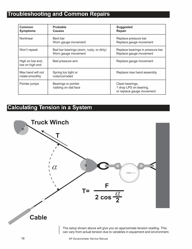
Troubleshooting and Common Repairs ................................................................................................................18
Calculating Tension in a System...........................................................................................................................18
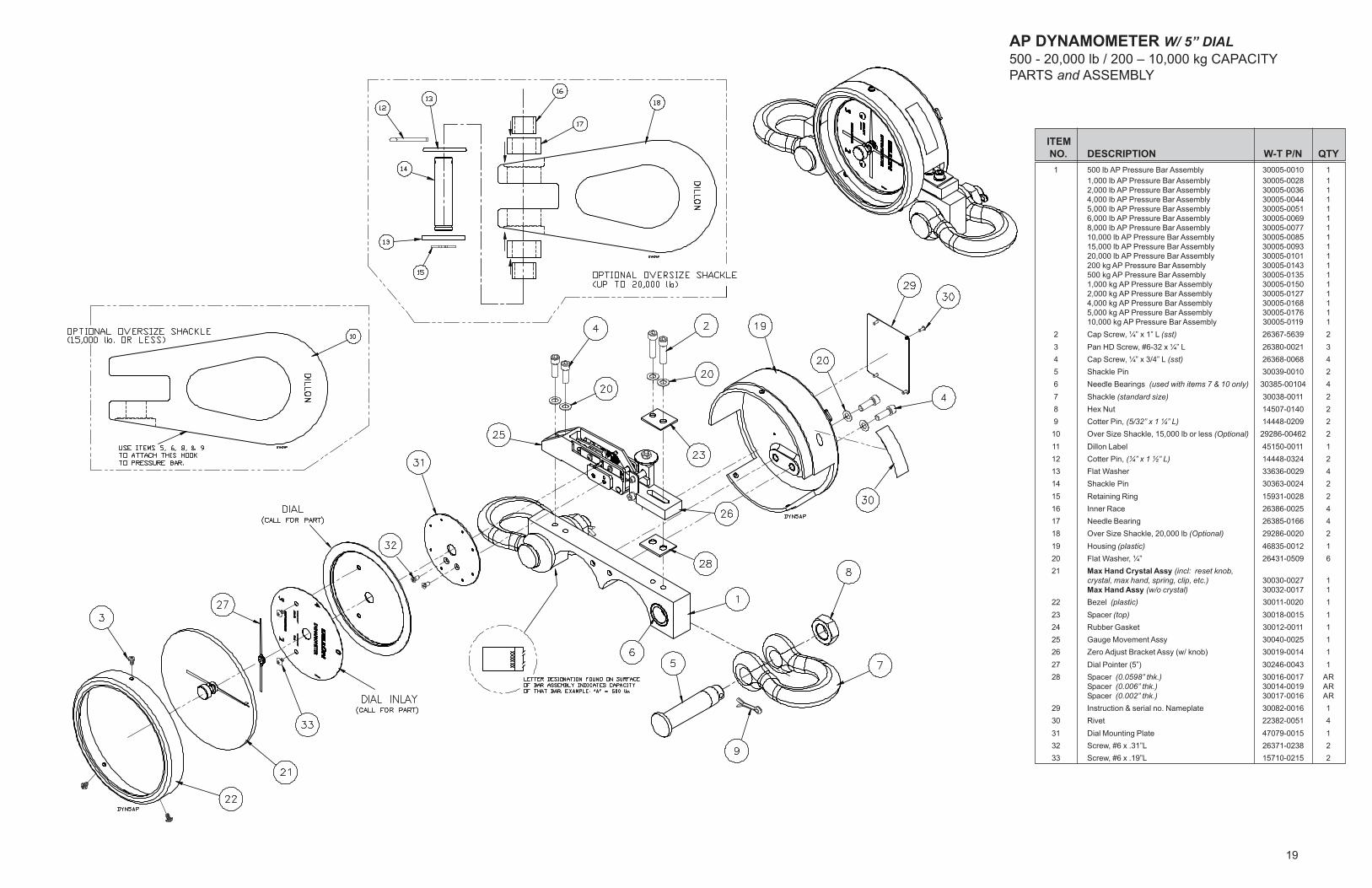
5” Dial (500-20,000 lb Cap.) Parts and Assembly .................................................................................................19
10” Dial (500-20,000 lb Cap.) Parts and Assembly ...............................................................................................20
10” Dial (30,000-50,000 lb Cap.) Parts and Assembly ..........................................................................................21
10” Dial (100,000 lb Cap.) Parts and Assembly ....................................................................................................22
Shackle/Pin Dimensional Outline Drawings..........................................................................................................23

4 AP Dynamometer Service Manual
5AP Dynamometer Service Manual
The popular Dillon Model AP dynamometer is a rugged, robust self-con-
tained and portable tension measuring instrument. Introduced in 1977, the
Model AP is the most widely used dynamometer in the field today in count-
less different applications.
The Dillon ProLift mechanical dynamometer supplemented the Dillon Model
AP dynamometer in 2001. Designed with the input of nuclear fuel handlers,
the ProLift satisfies all of the requirements for these ultra-sensitive applica-
tions. The ProLift offers the following enhancements over the Model AP:
� 5:1 Ultimate safety factor in all capacities
� Exclusive material selection
� Rounded pressure bar ends
� Electroless nickel plating
� Non-destructive examination of 100% of pressure bars in all capacities
� Non-destructive examination of 100% of low-capacity shackles and
shackle pins
� Proof-load tested to 150% of capacity
� Anchor shackles in all capacities
Dillon recommends that the ProLift should be the first choice when future
periodic non-destructive examination or proof loading is required.
These dynamometers are available in crane scale versions. These employ
hooks at the lower end, the large 10-inch diameter dial and are shipped in
plywood reinforced crates in all capacities.
In addition, Dillon offers a popular electronic dynamometer family and other
highly rated force measurement products. See www.dillon-force.com for
more information.
The Dillon Mechanical
Dynamometer Family
This service manual contains information needed for maintenance of Dillon
AP Dynamometers. Included in this manual are the following:
� instructions for disassembly and reassembly
� periodic inspection requirements and procedures
� instructions for calibration and zero adjustments
� technical illustrations
Service details for the ProLift dynamometer can be found in the separate
ProLift Dynamometer Service Manual.
About This Manual
6 AP Dynamometer Service Manual
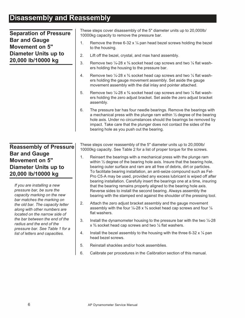
These steps cover disassembly of the 5" diameter units up to 20,000lb/
10000kg capacity to remove the pressure bar.
1. Remove the three 6-32 x ¼ pan head bezel screws holding the bezel
to the housing.
2. Lift off the bezel, crystal, and max hand assembly.
3. Remove two ¼-28 x ¾ socket head cap screws and two ¼ flat wash-
ers holding the housing to the pressure bar.
4. Remove two ¼-28 x ¾ socket head cap screws and two ¼ flat wash-
ers holding the gauge movement assembly. Set aside the gauge
movement assembly with the dial inlay and pointer attached.
5. Remove two ¼-28 x ¾ socket head cap screws and two ¼ flat wash-
ers holding the zero adjust bracket. Set aside the zero adjust bracket
assembly.
6. The pressure bar has four needle bearings. Remove the bearings with
a mechanical press with the plunge ram within ½ degree of the bearing
hole axis. Under no circumstances should the bearings be removed by
impact. Take care that the plunger does not contact the sides of the
bearing hole as you push out the bearing.
These steps cover reassembly of the 5" diameter units up to 20,000lb/
10000kg capacity. See Table 2 for a list of proper torque for the screws.
1. Reinsert the bearings with a mechanical press with the plunge ram
within ½ degree of the bearing hole axis. Insure that the bearing hole,
bearing outer surface and ram are all free of debris, dirt or particles.
To facilitate bearing installation, an anti-seize compound such as Fel-
Pro C5-A may be used, provided any excess lubricant is wiped off after
bearing installation. Carefully insert the bearings one at a time, insuring
that the bearing remains properly aligned to the bearing hole axis.
Reverse sides to install the second bearing. Always assembly the
bearing with the stamped end against the shoulder of the pressing tool.
2. Attach the zero adjust bracket assembly and the gauge movement
assembly with the four ¼-28 x ¾ socket head cap screws and four ¼
flat washers.
3. Install the dynamometer housing to the pressure bar with the two ¼-28
x ¾ socket head cap screws and two ¼ flat washers.
4. Install the bezel assembly to the housing with the three 6-32 x ¼ pan
head bezel screws.
5. Reinstall shackles and/or hook assemblies.
6. Calibrate per procedures in the Calibration section of this manual.
Separation of Pressure
Bar and Gauge
Movement on 5"
Diameter Units up to
20,000 lb/10000 kg
Reassembly of Pressure
Bar and Gauge
Movement on 5"
Diameter Units up to
20,000 lb/10000 kg
If you are installing a new
pressure bar, be sure the
capacity marking on the new
bar matches the marking on
the old bar. The capacity letter
along with other numbers are
located on the narrow side of
the bar between the end of the
radius and the end of the
pressure bar. See Table 1 for a
list of letters and capacities.
7AP Dynamometer Service Manual
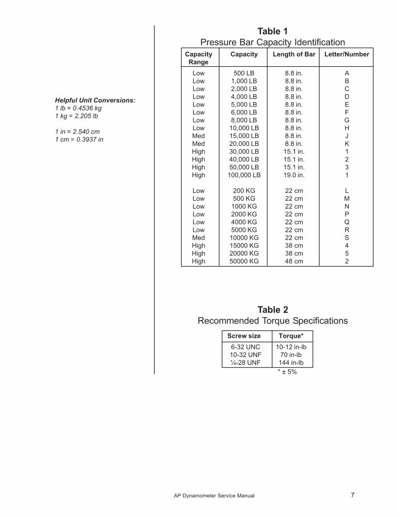
Table 1
Pressure Bar Capacity Identification
Capacity Capacity Length of Bar Letter/Number
Range
Low 500 LB 8.8 in. A
Low 1,000 LB 8.8 in. B
Low 2,000 LB 8.8 in. C
Low 4,000 LB 8.8 in. D
Low 5,000 LB 8.8 in. E
Low 6,000 LB 8.8 in. F
Low 8,000 LB 8.8 in. G
Low 10,000 LB 8.8 in. H
Med 15,000 LB 8.8 in. J
Med 20,000 LB 8.8 in. K
High 30,000 LB 15.1 in. 1
High 40,000 LB 15.1 in. 2
High 50,000 LB 15.1 in. 3
High 100,000 LB 19.0 in. 1
Low 200 KG 22 cm L
Low 500 KG 22 cm M
Low 1000 KG 22 cm N
Low 2000 KG 22 cm P
Low 4000 KG 22 cm Q
Low 5000 KG 22 cm R
Med 10000 KG 22 cm S
High 15000 KG 38 cm 4
High 20000 KG 38 cm 5
High 50000 KG 48 cm 2
Table 2
Recommended Torque Specifications
Screw size Torque*
6-32 UNC 10-12 in-lb
10-32 UNF 70 in-lb
¼-28 UNF 144 in-lb
* ± 5%
Helpful Unit Conversions:
1 lb = 0.4536 kg
1 kg = 2.205 lb
1 in = 2.540 cm
1 cm = 0.3937 in
8 AP Dynamometer Service Manual
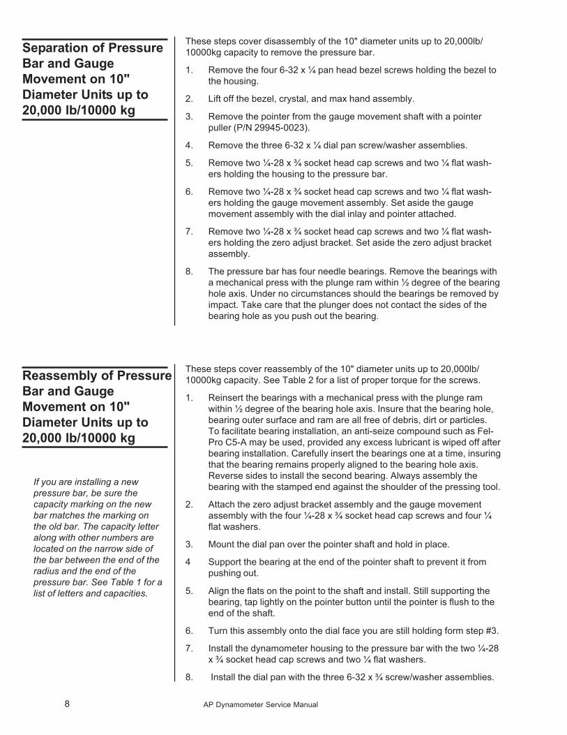
These steps cover disassembly of the 10" diameter units up to 20,000lb/
10000kg capacity to remove the pressure bar.
1. Remove the four 6-32 x ¼ pan head bezel screws holding the bezel to
the housing.
2. Lift off the bezel, crystal, and max hand assembly.
3. Remove the pointer from the gauge movement shaft with a pointer
puller (P/N 29945-0023).
4. Remove the three 6-32 x ¼ dial pan screw/washer assemblies.
5. Remove two ¼-28 x ¾ socket head cap screws and two ¼ flat wash-
ers holding the housing to the pressure bar.
6. Remove two ¼-28 x ¾ socket head cap screws and two ¼ flat wash-
ers holding the gauge movement assembly. Set aside the gauge
movement assembly with the dial inlay and pointer attached.
7. Remove two ¼-28 x ¾ socket head cap screws and two ¼ flat wash-
ers holding the zero adjust bracket. Set aside the zero adjust bracket
assembly.
8. The pressure bar has four needle bearings. Remove the bearings with
a mechanical press with the plunge ram within ½ degree of the bearing
hole axis. Under no circumstances should the bearings be removed by
impact. Take care that the plunger does not contact the sides of the
bearing hole as you push out the bearing.
These steps cover reassembly of the 10" diameter units up to 20,000lb/
10000kg capacity. See Table 2 for a list of proper torque for the screws.
1. Reinsert the bearings with a mechanical press with the plunge ram
within ½ degree of the bearing hole axis. Insure that the bearing hole,
bearing outer surface and ram are all free of debris, dirt or particles.
To facilitate bearing installation, an anti-seize compound such as Fel-
Pro C5-A may be used, provided any excess lubricant is wiped off after
bearing installation. Carefully insert the bearings one at a time, insuring
that the bearing remains properly aligned to the bearing hole axis.
Reverse sides to install the second bearing. Always assembly the
bearing with the stamped end against the shoulder of the pressing tool.
2. Attach the zero adjust bracket assembly and the gauge movement
assembly with the four ¼-28 x ¾ socket head cap screws and four ¼
flat washers.
3. Mount the dial pan over the pointer shaft and hold in place.
4 Support the bearing at the end of the pointer shaft to prevent it from
pushing out.
5. Align the flats on the point to the shaft and install. Still supporting the
bearing, tap lightly on the pointer button until the pointer is flush to the
end of the shaft.
6. Turn this assembly onto the dial face you are still holding form step #3.
7. Install the dynamometer housing to the pressure bar with the two ¼-28
x ¾ socket head cap screws and two ¼ flat washers.
8. Install the dial pan with the three 6-32 x ¾ screw/washer assemblies.
Separation of Pressure
Bar and Gauge
Movement on 10"
Diameter Units up to
20,000 lb/10000 kg
Reassembly of Pressure
Bar and Gauge
Movement on 10"
Diameter Units up to
20,000 lb/10000 kg
If you are installing a new
pressure bar, be sure the
capacity marking on the new
bar matches the marking on
the old bar. The capacity letter
along with other numbers are
located on the narrow side of
the bar between the end of the
radius and the end of the
pressure bar. See Table 1 for a
list of letters and capacities.
9AP Dynamometer Service Manual
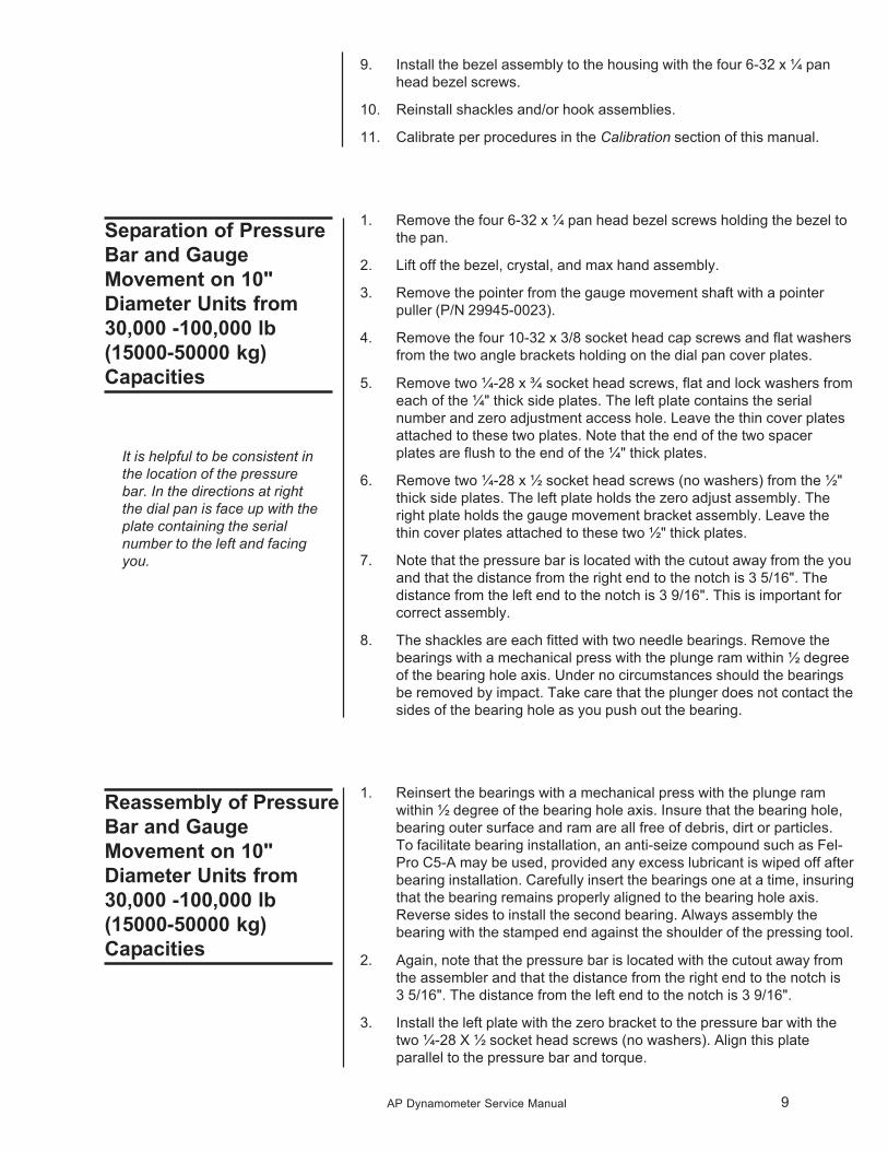
9. Install the bezel assembly to the housing with the four 6-32 x ¼ pan
head bezel screws.
10. Reinstall shackles and/or hook assemblies.
11. Calibrate per procedures in the Calibration section of this manual.
1. Remove the four 6-32 x ¼ pan head bezel screws holding the bezel to
the pan.
2. Lift off the bezel, crystal, and max hand assembly.
3. Remove the pointer from the gauge movement shaft with a pointer
puller (P/N 29945-0023).
4. Remove the four 10-32 x 3/8 socket head cap screws and flat washers
from the two angle brackets holding on the dial pan cover plates.
5. Remove two ¼-28 x ¾ socket head screws, flat and lock washers from
each of the ¼" thick side plates. The left plate contains the serial
number and zero adjustment access hole. Leave the thin cover plates
attached to these two plates. Note that the end of the two spacer
plates are flush to the end of the ¼" thick plates.
6. Remove two ¼-28 x ½ socket head screws (no washers) from the ½"
thick side plates. The left plate holds the zero adjust assembly. The
right plate holds the gauge movement bracket assembly. Leave the
thin cover plates attached to these two ½" thick plates.
7. Note that the pressure bar is located with the cutout away from the you
and that the distance from the right end to the notch is 3 5/16". The
distance from the left end to the notch is 3 9/16". This is important for
correct assembly.
8. The shackles are each fitted with two needle bearings. Remove the
bearings with a mechanical press with the plunge ram within ½ degree
of the bearing hole axis. Under no circumstances should the bearings
be removed by impact. Take care that the plunger does not contact the
sides of the bearing hole as you push out the bearing.
1. Reinsert the bearings with a mechanical press with the plunge ram
within ½ degree of the bearing hole axis. Insure that the bearing hole,
bearing outer surface and ram are all free of debris, dirt or particles.
To facilitate bearing installation, an anti-seize compound such as Fel-
Pro C5-A may be used, provided any excess lubricant is wiped off after
bearing installation. Carefully insert the bearings one at a time, insuring
that the bearing remains properly aligned to the bearing hole axis.
Reverse sides to install the second bearing. Always assembly the
bearing with the stamped end against the shoulder of the pressing tool.
2. Again, note that the pressure bar is located with the cutout away from
the assembler and that the distance from the right end to the notch is
3 5/16". The distance from the left end to the notch is 3 9/16".
3. Install the left plate with the zero bracket to the pressure bar with the
two ¼-28 X ½ socket head screws (no washers). Align this plate
parallel to the pressure bar and torque.
Separation of Pressure
Bar and Gauge
Movement on 10"
Diameter Units from
30,000 -100,000 lb
(15000-50000 kg)
Capacities
Reassembly of Pressure
Bar and Gauge
Movement on 10"
Diameter Units from
30,000 -100,000 lb
(15000-50000 kg)
Capacities
It is helpful to be consistent in
the location of the pressure
bar. In the directions at right
the dial pan is face up with the
plate containing the serial
number to the left and facing
you.
10 AP Dynamometer Service Manual
4. Install the right plate with the gauge movement bracket assembly. Tip
the plate downwards to engage the pressure arm into the zero adjust
bracket. Do not force. Attach with the two ¼-28 X ½ socket head
screws (no washers). Align this plate parallel to the pressure bar and
torque. Note that the left plate is narrower than the right plate by .040"
to clear the dial pan and eliminate interference during loading.
5. Install the right side ¼ inch thick cover plate with the spacer and attach
with two ¼-28 X ¾ socket head screws, flat and lock washers and
torque. The end of the spacer must be flush with the end of the plate.
6. Leave the remaining left ¼ inch thick cover plate and spacer until
calibration is completed.
7. Attach the dial pan with the four 10-32 X 3/8 socket head screws and
flat washers into the two angle brackets holding on the dial pan cover
plates. Align the hole at the center of the dial face with the pointer
shaft. Snug up the screws but do not tighten yet.
8. Align the flats and attach the pointer onto the gauge movement shaft
by hand. Use a flat screwdriver end or similar device to reach into the
housing to hold the lower shaft bearing from being driven out when
setting the pointer to the shaft. Tap the pointer hub to the shaft until
firm while holding the bearing from coming out.
9. While holding the pan, move the pointer clockwise at 90 degree
increments to determine that it is centered to the pan and that the pan
is uniform in height with the pointer. Now tighten the four socket head
screws that hold the pan to the mounting covers. Recheck the pointer
movement for interference and readjust if necessary.
10. Install the bezel to the pan with the four 6-32 X ¼ pan head screws.
11. Calibrate per the procedures in the Calibration section of this manual.
12. Now install the remaining ¼ inch serial I.D. cover plate with two ¼-28
X ¾ socket head screws, flat and lock washers and torque. Again, this
plate has .040" more clearance to the dial pan than the adjoining plate.
13. When reinstalling the shackles and/or swivel hook, install the snap ring
end of the 1" diameter mounting pin toward the dial side of the pres-
sure bar. Install the roll pin with more clearance on the other end.
If you are installing a new
pressure bar, be sure the
capacity marking on the new
bar matches the marking on
the old bar. The capacity letter
along with other numbers are
located on the end of the bar
with the 3 9/16" wide end. It is
on the outside corner which is
on the same side as the center
cutout. The identifier is the far
most right number in the string
of numbers. See Table 1 for a
list of letters and capacities.
11AP Dynamometer Service Manual
Clean the bezel with a soft cloth dampened using ordinary glass cleaner.
You can remove the bezel-retaining ring to clean the reverse side of the
bezel. Remove the ring by removing the Phillips screws that secure it to the
housing. The bezel edging material need not be removed for this cleaning.
Take care not to bend or damage the max pointer during cleaning. Reas-
semble in reverse order from disassembly.
Shackle-pin bearings should be cleaned if grease, grime or dirt is apparent
in the bearings. With the shackles and pins removed, apply a universal
cleaning degreaser (such as Blue Shower, CRC Heavy Duty Degreaser,
Safety-Kleen Solvent, etc.) directly to the bearings. Manually turn the bear-
ings and continue applying cleaner until traces of dirt disappears. Sparingly
apply a light lubricant (such as Ace LPS2, Exxon Handy Oil, 3 in 1 oil, etc.)
to coat all moving surfaces.
The gearing works or mechanical mechanisms within the dynamometer
housing can be cleaned with a cleaning degreaser and then sparingly
lubricated with a light lubricant.
The remainder of the dynamometer may be cleaned with a light-duty,
general purpose cleaner.
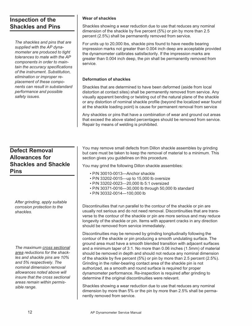
In service, the pressure bar should not be permitted to contact or otherwise
sustain impression or impact
loads.
Any pressure bar with cracks or
sharp gashes should be immedi-
ately removed from service. Any
pits, impressions, or other surface
inconsistencies larger than 0.031
(1/32) inch are cause for replace-
ment. Smooth or rounded imper-
fections with depths less than
0.062 (1/16) inch are permissible
on the corners indicated in the illustration at right.
Scratches across the bearing hole greater than 0.005 inch in depth are
cause for replacement. Machining marks running the circumference of the
bearing hole are not cause for rejection.
Under no circumstances should any surface of the pressure bar be sub-
jected to grinding. The pressure bar cannot be repaired by welding.
For organizations that perform periodic nondestructive testing of the pres-
sure bar, relevancy checks may be performed using a Dremmel type tool
and fine grit drum, flexible disc, or buffer type attachments, such that the
resulting finish is no worse than 63 micro inches and the depth is not greater
than 0.005 inches. Any one location may only be relevancy checked once
during the lifetime of the pressure bar. Relevancy checks may not be
performed in the area of the stamped traceability numbers.
Cleaning And
Lubrication
Inspection of the
Pressure Bar
12 AP Dynamometer Service Manual
Wear of shackles
Shackles showing a wear reduction due to use that reduces any nominal
dimension of the shackle by five percent (5%) or pin by more than 2.5
percent (2.5%) shall be permanently removed from service.
For units up to 20,000 lbs, shackle pins found to have needle bearing
impression marks not greater than 0.004 inch deep are acceptable provided
the dynamometer calibrates satisfactorily. If the impression marks are
greater than 0.004 inch deep, the pin shall be permanently removed from
service.
Deformation of shackles
Shackles that are determined to have been deformed (aside from local
distortion at contact sites) shall be permanently removed from service. Any
visually apparent bending or twisting out of the natural plane of the shackle
or any distortion of nominal shackle profile (beyond the localized wear found
at the shackle loading point) is cause for permanent removal from service
Any shackles or pins that have a combination of wear and ground out areas
that exceed the above stated percentages should be removed from service.
Repair by means of welding is prohibited.
You may remove small defects from Dillon shackle assembles by grinding
but care must be taken to keep the removal of material to a minimum. This
section gives you guidelines on this procedure.
You may grind the following Dillon shackle assemblies:
� P/N 30010-0013—Anchor shackle
� P/N 33202-0015—up to 15,000 lb oversize
� P/N 33202-0023—20,000 lb 5:1 oversized
� P/N 30371-0016—30,000 lb through 50,000 lb standard
� P/N 30332-0014—100,000 lb
Discontinuities that run parallel to the contour of the shackle or pin are
usually not serious and do not need removal. Discontinuities that are trans-
verse to the contour of the shackle or pin are more serious and may reduce
longevity of the shackle or pin. Items with apparent cracks in any direction
should be removed from service immediately.
Discontinuities may be removed by grinding longitudinally following the
contour of the shackle or pin producing a smooth undulating surface. The
ground area must have a smooth blended transition with adjacent surfaces
and a minimum taper of 3:1. No more than 0.06 inches (1.5mm) of material
should be removed in depth and should not reduce any nominal dimension
of the shackle by five percent (5%) or pin by more than 2.5 percent (2.5%).
Grinding in the roller-bearing contact area of the shackle pin is not
authorized, as a smooth and round surface is required for proper
dynamometer performance. Re-inspection is required after grinding to
determine if the original discontinuities were relevant.
Shackles showing a wear reduction due to use that reduces any nominal
dimension by more than 5% or the pin by more than 2.5% shall be perma-
nently removed from service.
Inspection of the
Shackles and Pins
Defect Removal
Allowances for
Shackles and Shackle
Pins
After grinding, apply suitable
corrosion protection to the
shackles.
The shackles and pins that are
supplied with the AP dyna-
mometer are produced to tight
tolerances to mate with the AP
components in order to main-
tain the accuracy specifications
of the instrument. Substitution,
elimination or improper re-
placement of these compo-
nents can result in substandard
performance and possible
safety issues.
The maximum cross sectional
area reductions for the shack-
les and shackle pins are 10%
and 5% respectively. The
nominal dimension removal
allowances noted above will
insure that the cross sectional
areas remain within permis-
sible range.
13AP Dynamometer Service Manual
Minor scratches and dents may be removed from AP Dynamometer pres-
sure bars using the following criteria and guidelines:
1. This type of action may not take place in any one location more than
once during the life of the unit. Use a Dremmel type drum, flexible disk,
or buffer attachments to remove scratches and dents. No more than
.005 inch may be removed from the surface of the pressure bar.
2. The grit of the tool must be fine enough that the result is no worse than
a 63 microinch surface finish.
3. On square corners, material may be removed to a depth of 1/16 inch
as measured from the corner, due to these areas being at very low
stress levels during use. Blunt dents less than 1/16 inch deep from the
corner do not require removal for safe operation.
4. The serial number and traceability information is stamped near one of
these low stress corners. Do not use a material removal tool in the
area of these stamped numbers in order to maintain traceability.
Repair by welding is not authorized.
The Dillon Model AP mechanical dynamometer may be subjected to 150%
proof loads of the rated capacity up to twice per year for inspection pur-
poses. The applied loads must not exceed 155% of capacity of the instru-
ment. The load may be held for any period desired provided the load does
not cycle or vary. The proof load must be conducted in a controlled area with
appropriate safety mechanisms in place. The dynamometer itself should not
provide the load reference during the test.
Original shackle pins should not be proof loaded on the 15,000-lb, 20,000-lb
and 10000-kg Model AP dynamometers with the standard anchor shackle.
The bearings can apply impressions to the shackle pins that can negatively
affect performance. Substitute shackle pins should be used in proof loading
to eliminate potential for distorting these pins. Shackle pins that require
testing should be proof loaded independently in a fixture with smooth contact
surfaces.
The dynamometers will not experience mechanical damage under a 150%
proof load, however the calibration and zero reference point may be altered.
Recalibration will restore the original performance.
Defect Removal
Allowances for
Pressure Bars
After grinding, apply suitable
corrosion protection to the
pressure bars.
Proof Loading
14 AP Dynamometer Service Manual
Procedure for 20,000 lb
(10000 kg) and Below
Span adjustment procedure
Only Dillon shackles and pins
should be used with the
dynamometer during calibra-
tion or use. For best instrument
performance, use the shackles
and pins during calibration that
are used during routine use.
Typical recalibration interval is
every 12 months, although
more frequent calibration is
suggested for dynamometers
in extreme service.
The shackle bearings included
with the dynamometer must be
used during calibration and
operation. These bearings are
installed in the dynamometer
and facilitate predictable and
repeatable rotational movement
of the pressure arm under load.
We do not recommend that the
instruments be calibrated or
have any type of performance
reviewed with the bearings
removed.
Equipment required:
� load frame, dead weights, or lever system
� applicable fixturing for applying load to the device
� torque wrench with 3/16 inch hex drive socket
The calibration technician must be qualified for and trained in the proce-
dures for operating the calibration machine, adjusting the calibration of the
device, and recording of the calibration data.
1. Service the dynamometer. Inspect the unit for damage, and the
condition of all load bearing surfaces. Replace or repair parts and
assemblies as required. Leave the crystal off the unit until the device
has been recalibrated after repair.
2. Dynamometers received for recalibration and repair that are functional
should have “as found” readings taken. Install the dynamometer and
shackles in the calibration machine.
3. Check the maximum hand adjustment and record the number of
divisions to the nearest half division the maximum hand will move the
dynamometer pointer in a counter clockwise direction.
4. Exercise the unit three times by applying 1.00 to 1.05 times rated
capacity load and then releasing the load completely. Observe the
smoothness of pointer travel throughout the full range. Zero the pointer
and calibration transfer standard indicator.
5. Apply four to five point calibration with the pointer and division mark
aligned at each reading as found.
6a. Apply the rated capacity load with the unit pointer and division mark
aligned. Move the zero adjusting bracket towards the center of the unit
if the load shown on the calibration machine indicator is greater than
the rated dynamometer load. Move the bracket away from the center
of the unit if the load shown on the calibration machine indicator is less
than the rated dynamometer load. Repeat this procedure until the unit
is properly spanned.
6b. Tighten the zero adjustment bracket cap screws to 144 +/- 8 inch
pounds torque.
7a. Linearity adjustment procedure. Slight adjustments can be made to the
midrange readings of the dynamometer.
7b. Loosen the two dial retaining screws. Load the dynamometer until the
pointer and the one half of rated capacity division mark are aligned.
Shift the bottom of the dial to the right if the load shown on the calibra-
tion machine indicator is greater than the half scale dynamometer load.
Shift the bottom of the dial to the left if the load shown on the calibra-
tion machine indicator is less than the half scale dynamometer load.
7c. Tighten the two dial retaining screws and recheck the span adjustment
of the unit. Readjust the unit span and linearity as required.
15AP Dynamometer Service Manual
8. Install the maximum pointer assembly, bezel, and housing on the
dynamometer. Check the maximum hand adjustment. The maximum
hand turned counter clockwise must not move the dynamometer
pointer more than one division before the clutch mechanism slips.
Readjust the clutch mechanism as required.
9. Affix a calibration cover label seal over the zero adjusting bracket
access hole as required. Remove the dynamometer and any shackles
from the calibration standard machine.
10. Verify the calibration entries satisfy the dynamometer accuracy specifi-
cation. Enter the dynamometer serial number, the verified accuracy
tolerance percentage, sign, and date the certificate of calibration card.
16 AP Dynamometer Service Manual
Equipment required:
� load frame, dead weights, or lever system
� applicable fixturing for applying load to the device
� torque wrench with 3/16 inch hex drive socket
The calibration technician must be qualified for and trained in the proce-
dures for operating the calibration machine, adjusting the calibration of the
device, and recording of the calibration data.
You should have assistance from the department or other areas in manipu-
lating large heavy dynamometer assemblies into and out of the calibration
machine.
1. Service the dynamometer. Inspect the unit for damage, and the
condition of all load bearing surfaces. Replace or repair parts and
assemblies as required. Leave the crystal off the unit until the device
has been recalibrated after repair. Leave the serial plate cover off the
unit.
2. Dynamometers received for recalibration and repair that are functional
should have “as found” readings taken. Install the dynamometer and
shackles in the calibration machine.
3. Check the maximum hand adjustment and record the number of
divisions to the nearest half division the maximum hand will move the
dynamometer pointer in a counter clockwise direction.
4. Exercise the unit three times by applying 1.00 to 1.05 times rated
capacity load and then releasing the load completely. Observe the
smoothness of pointer travel throughout the full range. Zero the pointer
and calibration transfer standard indicator.
5. Apply four to five point calibration with the pointer and division mark
aligned at each reading.
6a. Apply the rated capacity load with the unit pointer and division mark
aligned. Move the zero adjusting bracket towards the center of the unit
if the load shown on the calibration machine indicator is greater than
the rated dynamometer load. Move the bracket away from the center
of the unit if the load shown on the calibration machine indicator is less
than the rated dynamometer load. Repeated this procedure until the
unit is spanned.
6b. Tighten the zero adjustment bracket cap screws to 144 +/- 8 inch
pounds torque.
7. Linearity adjustment procedure. Slight adjustments can be made to the
midrange readings of the dynamometer.
8a. Loosen the two dial retaining screws. Load the dynamometer until the
pointer and the one half of rated capacity division mark are aligned.
Shift the bottom of the dial to the right if the load shown on the calibra-
tion machine indicator is greater than the half scale dynamometer load.
Shift the bottom of the dial to the left if the load shown on the calibra-
tion machine indicator is less than the half scale dynamometer load.
8b. Tighten the two dial retaining screws and recheck the span adjustment
of the unit. Apply five point calibration with the pointer and division
mark aligned at each reading. Readjust the unit span and linearity as
required.
Procedure for 30,000 lb
(15000 kg) and Higher
Span adjustment procedure
Typical recalibration interval is
every 12 months, although
more frequent calibration is
suggested for dynamometers
in extreme service.
Only Dillon shackles and pins
should be used with the
dynamometer during calibra-
tion or use. For best instrument
performance, use the shackles
and pins during calibration that
are used during routine use.
The shackle bearings included
with the dynamometer must be
used during calibration and
operation. These bearings are
installed in the dynamometer
and facilitate predictable and
repeatable rotational movement
of the pressure arm under load.
We do not recommend that the
instruments be calibrated or
have any type of performance
reviewed with the bearings
removed.
17AP Dynamometer Service Manual
9. Install the maximum pointer assembly, bezel, and serial plate cover on
the dynamometer. Check the maximum hand adjustment. The maxi-
mum hand turned counter clockwise must not move the dynamometer
pointer more than one division before the clutch mechanism slips.
Readjust the clutch mechanism as required.
10. Apply five point calibration with the pointer and division mark aligned at
each reading.
11. Remove the dynamometer and shackles from the calibration standard
machine.
12. Verify the calibration data satisfy the dynamometer accuracy specifica-
tion. Enter the dynamometer serial number, the verified accuracy
tolerance percentage, sign, and date the certificate of calibration card.
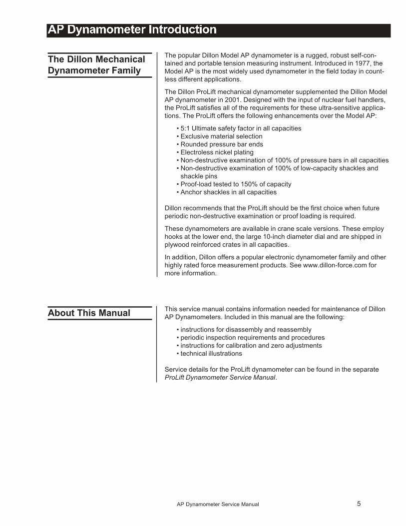
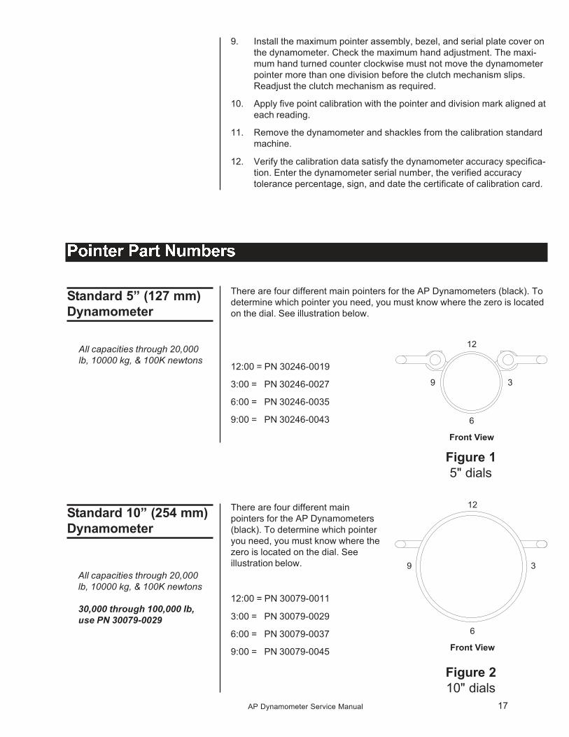
There are four different main pointers for the AP Dynamometers (black). To
determine which pointer you need, you must know where the zero is located
on the dial. See illustration below.
12:00 = PN 30246-0019
3:00 = PN 30246-0027
6:00 = PN 30246-0035
9:00 = PN 30246-0043
Standard 5” (127 mm)
Dynamometer
There are four different main
pointers for the AP Dynamometers
(black). To determine which pointer
you need, you must know where the
zero is located on the dial. See
illustration below.
12:00 = PN 30079-0011
3:00 = PN 30079-0029
6:00 = PN 30079-0037
9:00 = PN 30079-0045
Standard 10” (254 mm)
Dynamometer
All capacities through 20,000
lb, 10000 kg, & 100K newtons
All capacities through 20,000
lb, 10000 kg, & 100K newtons
30,000 through 100,000 lb,
use PN 30079-0029
Figure 1
5" dials
Figure 2
10" dials
18 AP Dynamometer Service Manual
Common Probable Suggested
Symptoms Causes Repair
Nonlinear Bent bar Replace pressure bar
Worn gauge movement Replace gauge movement
Won’t repeat Bad bar bearings (worn, rusty, or dirty) Replace bearings in pressure bar
Worn gauge movement Replace gauge movement
High on low end, Bad pressure arm Replace gauge movement
low on high end
Max hand will not Spring too tight or Replace max hand assembly
rotate smoothly rusty/corroded
Pointer jumps Bearings or pointer Clean bearings,
rubbing on dial face 1 drop LPS on bearing,
or replace gauge movement
The setup shown above will give you an approximate tension reading. This
can vary from actual tension due to variables in equipment and environment.
19
ITEM
NO. DESCRIPTION W-T P/N QTY
1 500 lb AP Pressure Bar Assembly 30005-0010 1
1,000 lb AP Pressure Bar Assembly 30005-0028 1
2,000 lb AP Pressure Bar Assembly 30005-0036 1
4,000 lb AP Pressure Bar Assembly 30005-0044 1
5,000 lb AP Pressure Bar Assembly 30005-0051 1
6,000 lb AP Pressure Bar Assembly 30005-0069 1
8,000 lb AP Pressure Bar Assembly 30005-0077 1
10,000 lb AP Pressure Bar Assembly 30005-0085 1
15,000 lb AP Pressure Bar Assembly 30005-0093 1
20,000 lb AP Pressure Bar Assembly 30005-0101 1
200 kg AP Pressure Bar Assembly 30005-0143 1
500 kg AP Pressure Bar Assembly 30005-0135 1
1,000 kg AP Pressure Bar Assembly 30005-0150 1
2,000 kg AP Pressure Bar Assembly 30005-0127 1
4,000 kg AP Pressure Bar Assembly 30005-0168 1
5,000 kg AP Pressure Bar Assembly 30005-0176 1
10,000 kg AP Pressure Bar Assembly 30005-0119 1
2 Cap Screw, ¼” x 1” L (sst) 26367-5639 2
3 Pan HD Screw, #6-32 x ¼” L 26380-0021 3
4 Cap Screw, ¼” x 3/4” L (sst) 26368-0068 4
5 Shackle Pin 30039-0010 2
6 Needle Bearings (used with items 7 & 10 only) 30385-00104 4
7 Shackle (standard size) 30038-0011 2
8 Hex Nut 14507-0140 2
9 Cotter Pin, (5/32” x 1 ¼” L) 14448-0209 2
10 Over Size Shackle, 15,000 lb or less (Optional) 29286-00462 2
11 Dillon Label 45150-0011 1
12 Cotter Pin, (¼” x 1 ½” L) 14448-0324 2
13 Flat Washer 33636-0029 4
14 Shackle Pin 30363-0024 2
15 Retaining Ring 15931-0028 2
16 Inner Race 26386-0025 4
17 Needle Bearing 26385-0166 4
18 Over Size Shackle, 20,000 lb (Optional) 29286-0020 2
19 Housing (plastic) 46835-0012 1
20 Flat Washer, ¼” 26431-0509 6
21 Max Hand Crystal Assy (incl: reset knob,
crystal, max hand, spring, clip, etc.) 30030-0027 1
Max Hand Assy (w/o crystal) 30032-0017 1
22 Bezel (plastic) 30011-0020 1
23 Spacer (top) 30018-0015 1
24 Rubber Gasket 30012-0011 1
25 Gauge Movement Assy 30040-0025 1
26 Zero Adjust Bracket Assy (w/ knob) 30019-0014 1
27 Dial Pointer (5”) 30246-0043 1
28 Spacer (0.0598” thk.) 30016-0017 AR
Spacer (0.006” thk.) 30014-0019 AR
Spacer (0.002” thk.) 30017-0016 AR
29 Instruction & serial no. Nameplate 30082-0016 1
30 Rivet 22382-0051 4
31 Dial Mounting Plate 47079-0015 1
32 Screw, #6 x .31”L 26371-0238 2
33 Screw, #6 x .19”L 15710-0215 2
AP DYNAMOMETER W/ 5” DIAL
500 - 20,000 lb / 200 – 10,000 kg CAPACITY
PARTS and ASSEMBLY
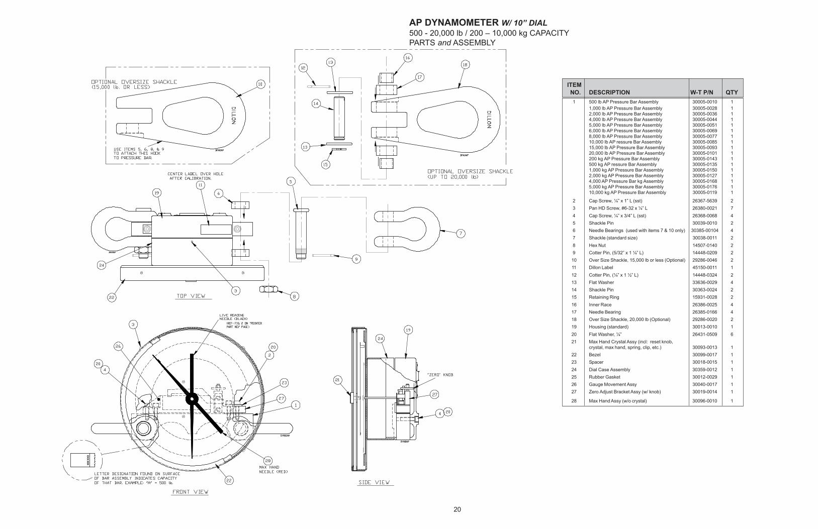
20
ITEM
NO. DESCRIPTION W-T P/N QTY
1 500 lb AP Pressure Bar Assembly 30005-0010 1
1,000 lb AP Pressure Bar Assembly 30005-0028 1
2,000 lb AP Pressure Bar Assembly 30005-0036 1
4,000 lb AP Pressure Bar Assembly 30005-0044 1
5,000 lb AP Pressure Bar Assembly 30005-0051 1
6,000 lb AP Pressure Bar Assembly 30005-0069 1
8,000 lb AP Pressure Bar Assembly 30005-0077 1
10,000 lb AP ressure Bar Assembly 30005-0085 1
15,000 lb AP Pressure Bar Assembly 30005-0093 1
20,000 lb AP Pressure Bar Assembly 30005-0101 1
200 kg AP Pressure Bar Assembly 30005-0143 1
500 kg AP ressure Bar Assembly 30005-0135 1
1,000 kg AP Pressure Bar Assembly 30005-0150 1
2,000 kg AP Pressure Bar Assembly 30005-0127 1
4,000 AP Pressure Bar kg Assembly 30005-0168 1
5,000 kg AP Pressure Bar Assembly 30005-0176 1
10,000 kg AP Pressure Bar Assembly 30005-0119 1
2 Cap Screw, ¼” x 1” L (sst) 26367-5639 2
3 Pan HD Screw, #6-32 x ¼” L 26380-0021 7
4 Cap Screw, ¼” x 3/4” L (sst) 26368-0068 4
5 Shackle Pin 30039-0010 2
6 Needle Bearings (used with items 7 & 10 only) 30385-00104 4
7 Shackle (standard size) 30038-0011 2
8 Hex Nut 14507-0140 2
9 Cotter Pin, (5/32” x 1 ¼” L) 14448-0209 2
10 Over Size Shackle, 15,000 lb or less (Optional) 29286-0046 2
11 Dillon Label 45150-0011 1
12 Cotter Pin, (¼” x 1 ½” L) 14448-0324 2
13 Flat Washer 33636-0029 4
14 Shackle Pin 30363-0024 2
15 Retaining Ring 15931-0028 2
16 Inner Race 26386-0025 4
17 Needle Bearing 26385-0166 4
18 Over Size Shackle, 20,000 lb (Optional) 29286-0020 2
19 Housing (standard) 30013-0010 1
20 Flat Washer, ¼” 26431-0509 6
21 Max Hand Crystal Assy (incl: reset knob,
crystal, max hand, spring, clip, etc.) 30093-0013 1
22 Bezel 30099-0017 1
23 Spacer 30018-0015 1
24 Dial Case Assembly 30359-0012 1
25 Rubber Gasket 30012-0029 1
26 Gauge Movement Assy 30040-0017 1
27 Zero Adjust Bracket Assy (w/ knob) 30019-0014 1
28 Max Hand Assy (w/o crystal) 30096-0010 1
AP DYNAMOMETER W/ 10” DIAL
500 - 20,000 lb / 200 – 10,000 kg CAPACITY
PARTS and ASSEMBLY
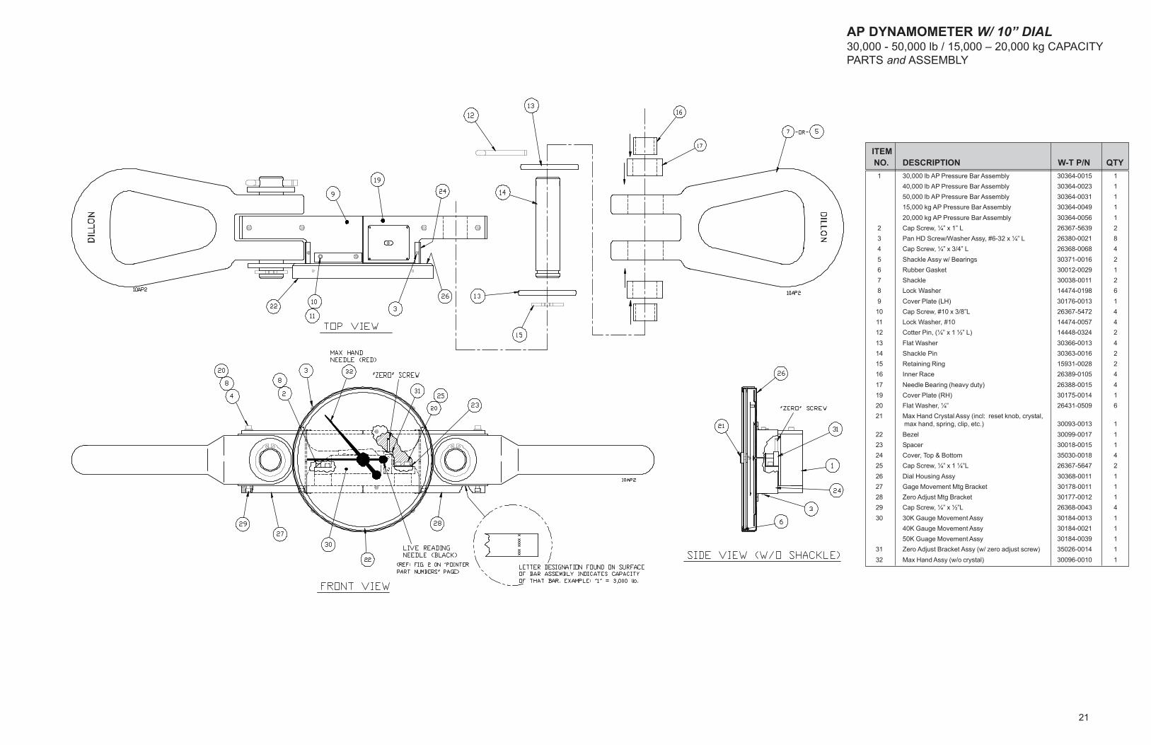
21
ITEM
NO. DESCRIPTION W-T P/N QTY
1 30,000 lb AP Pressure Bar Assembly 30364-0015 1
40,000 lb AP Pressure Bar Assembly 30364-0023 1
50,000 lb AP Pressure Bar Assembly 30364-0031 1
15,000 kg AP Pressure Bar Assembly 30364-0049 1
20,000 kg AP Pressure Bar Assembly 30364-0056 1
2 Cap Screw, ¼” x 1” L 26367-5639 2
3 Pan HD Screw/Washer Assy, #6-32 x ¼” L 26380-0021 8
4 Cap Screw, ¼” x 3/4” L 26368-0068 4
5 Shackle Assy w/ Bearings 30371-0016 2
6 Rubber Gasket 30012-0029 1
7 Shackle 30038-0011 2
8 Lock Washer 14474-0198 6
9 Cover Plate (LH) 30176-0013 1
10 Cap Screw, #10 x 3/8”L 26367-5472 4
11 Lock Washer, #10 14474-0057 4
12 Cotter Pin, (¼” x 1 ½” L) 14448-0324 2
13 Flat Washer 30366-0013 4
14 Shackle Pin 30363-0016 2
15 Retaining Ring 15931-0028 2
16 Inner Race 26389-0105 4
17 Needle Bearing (heavy duty) 26388-0015 4
19 Cover Plate (RH) 30175-0014 1
20 Flat Washer, ¼” 26431-0509 6
21 Max Hand Crystal Assy (incl: reset knob, crystal,
max hand, spring, clip, etc.) 30093-0013 1
22 Bezel 30099-0017 1
23 Spacer 30018-0015 1
24 Cover, Top & Bottom 35030-0018 4
25 Cap Screw, ¼” x 1 ¼”L 26367-5647 2
26 Dial Housing Assy 30368-0011 1
27 Gage Movement Mtg Bracket 30178-0011 1
28 Zero Adjust Mtg Bracket 30177-0012 1
29 Cap Screw, ¼” x ½”L 26368-0043 4
30 30K Gauge Movement Assy 30184-0013 1
40K Gauge Movement Assy 30184-0021 1
50K Guage Movement Assy 30184-0039 1
31 Zero Adjust Bracket Assy (w/ zero adjust screw) 35026-0014 1
32 Max Hand Assy (w/o crystal) 30096-0010 1
AP DYNAMOMETER W/ 10” DIAL30,000 - 50,000 lb / 15,000 – 20,000 kg CAPACITY
PARTS and ASSEMBLY
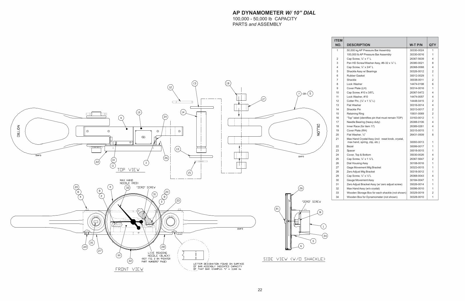
22
ITEM
NO. DESCRIPTION W-T P/N QTY
1 50,000 kg AP Pressure Bar Assembly 30330-0024 1
100,000 lb AP Pressure Bar Assembly 30330-0016 1
2 Cap Screw, ¼” x 1” L 26367-5639 4
3 Pan HD Screw/Washer Assy, #6-32 x ¼” L 26380-0021 8
4 Cap Screw, ¼” x 3/4” L 26368-0068 4
5 Shackle Assy w/ Bearings 30326-0012 2
6 Rubber Gasket 30012-0029 1
7 Shackle 30038-0011 2
8 Lock Washer 14474-0198 6
9 Cover Plate (LH) 30314-0016 1
10 Cap Screw, #10 x 3/8”L 26367-5472 4
11 Lock Washer, #10 14474-0057 4
12 Cotter Pin, (¼” x 1 ½” L) 14448-0415 2
13 Flat Washer 30316-0014 4
14 Shackle Pin 30313-0017 2
15 Retaining Ring 15931-0069 2
16 “Top” label (identifies pin that must remain TOP) 33163-0012 1
17 Needle Bearing (heavy duty) 26388-0106 4
18 Inner Race (for item 17) 26389-0261 4
19 Cover Plate (RH) 30315-0015 1
20 Flat Washer, ¼” 26431-0509 8
21 Max Hand Crystal Assy (incl: reset knob, crystal,
max hand, spring, clip, etc.) 30093-0013 1
22 Bezel 30099-0017 1
23 Spacer 30018-0015 1
24 Cover, Top & Bottom 35030-0026 4
25 Cap Screw, ¼” x 1 ¼”L 26367-5647 2
26 Dial Housing Assy 30108-0016 1
27 Gage Movement Mtg Bracket 30323-0015 1
28 Zero Adjust Mtg Bracket 30318-0012 1
29 Cap Screw, ¼” x ½”L 26368-0043 4
30 Gauge Movement Assy 30184-0047 1
31 Zero Adjust Bracket Assy (w/ zero adjust screw) 35026-0014 1
32 Max Hand Assy (w/o crystal) 30096-0010 1
33 Wooden Storage Box for each shackle (not shown) 30329-0019 2
34 Wooden Box for Dynamometer (not shown) 30328-0010 1
AP DYNAMOMETER W/ 10” DIAL100,000 - 50,000 lb CAPACITY
PARTS and ASSEMBLY
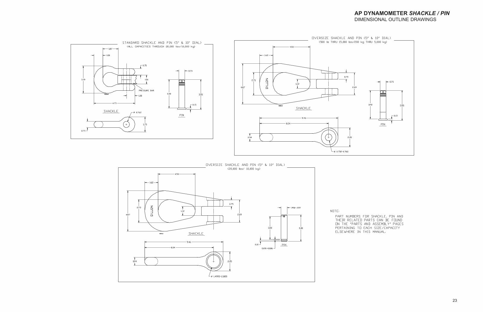
23
AP DYNAMOMETER SHACKLE / PINDIMENSIONAL OUTLINE DRAWINGS
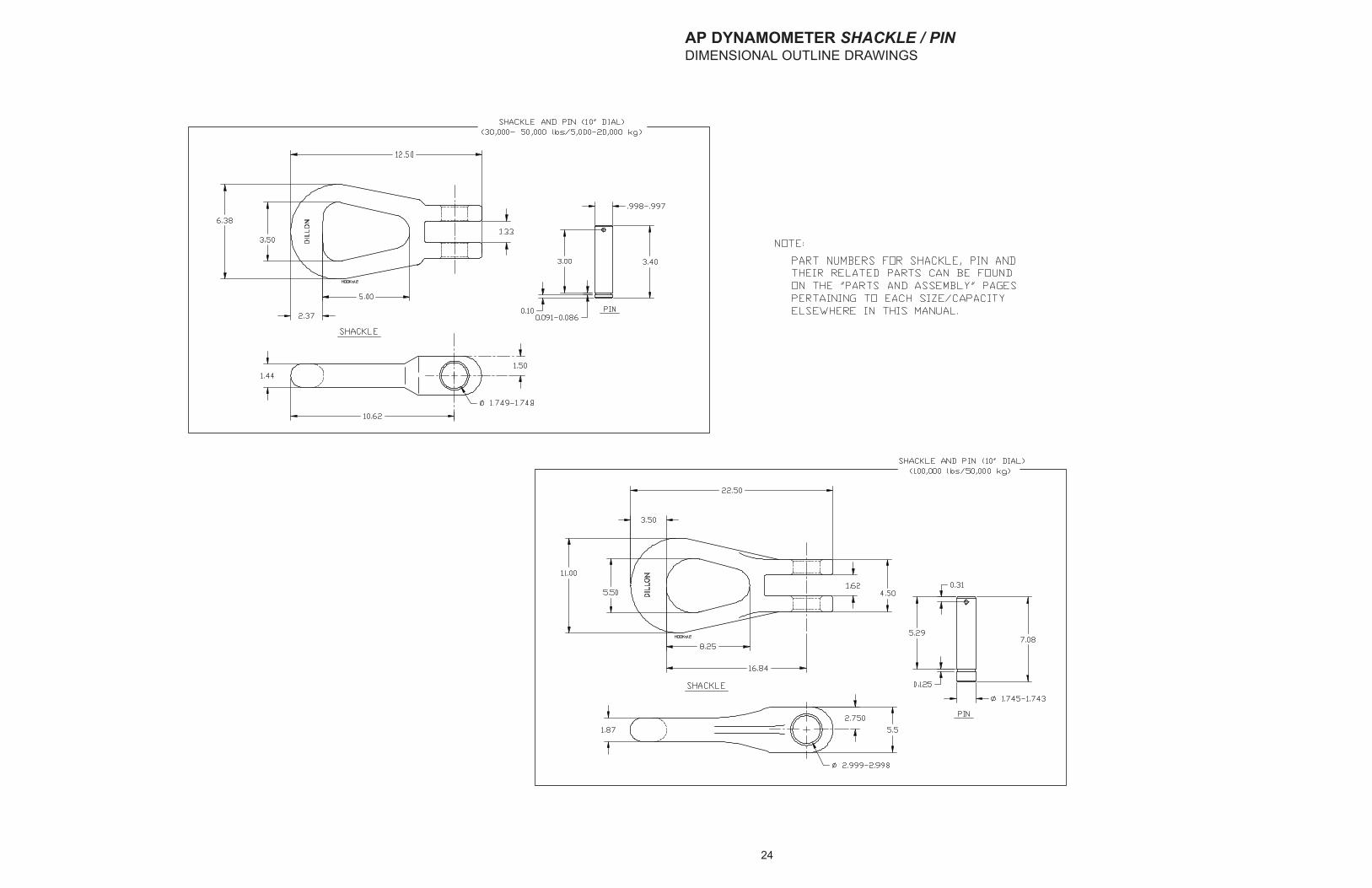
24
AP DYNAMOMETER SHACKLE / PINDIMENSIONAL OUTLINE DRAWINGS