Embed Size (px)
Citation preview
MD-1750 SERIESC H A S S I S D Y N A M O M E T E R
Maintenance & Service Manual

2300 Pinnacle ParkwayTwinsburg, Ohio 44087 USA
Ph: (330) 963-5400Fax (330) 425-3310
www.mustangdyne.com
ii
Information in this document is subject to change without notice. No part of this document may be reproduced or transmitted in any form or by any means, electrical or mechanical, for any purpose, without the express written permission of Mustang Dynamometer.
Copyright © 2004 Ganzcorp Investments, Inc. dba Mustang Dynamometer
All rights reserved
NOTICEThis manual has been designed and written to provide useful information about Mustang Dynamometer equipment and systems. Every effort has been made to make this manual as complete and accurate as possible, but no warranty or fitness is implied.
The information contained in this manual is provided on an "as is" basis. Neither the author of this manual nor the management and owners of Mustang Dynamometer shall have either liability or responsibility to any person or entity with respect to any loss or damages arising from the information contained in this manual.
2300 Pinnacle ParkwayTwinsburg, Ohio 44087 USA
Ph: (330) 963-5400Fax (330) 425-3310
www.mustangdyne.com
MD-1750 Chassis DynamometerMaintenance & Service Manual
MD-1750 Chassis DynamometerMaintenance & Service Manual
MD-1750 Chassis DynamometerMaintenance & Service Manual
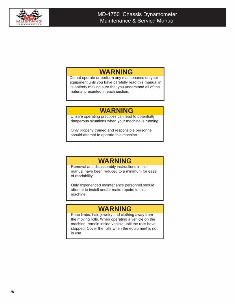
WARNINGUnsafe operating practices can lead to potentially dangerous situations when your machine is running.
Only properly trained and responsible personnel should attempt to operate this machine.
WARNINGDo not operate or perform any maintenance on your equipment until you have carefully read this manual in its entirety making sure that you understand all of the material presented in each section.
WARNINGRemoval and disassembly instructions in this manual have been reduced to a minimum for ease of readability.
Only experienced maintenance personnel should attempt to install and/or make repairs to this machine.
WARNINGKeep limbs, hair, jewelry and clothing away from the moving rolls. When operating a vehicle on the machine, remain inside vehicle until the rolls have stopped. Cover the rolls when the equipment is not in use.
MD-1750 Chassis Dynamometer
iii

MD-1750 Chassis DynamometerMaintenance & Service Manual
MD-1750 Chassis DynamometerMaintenance & Service Manual
WARRANTYLIMIT OF LIABILITY
Mustang warrants that the product(s) that is the subject of this sale is free from defects in material. The duration of this warranty is one year from date of shipment on all Mustang-related components. Components not manufactured by Mustang will carry the original manufacturer's warranty, typically 90 days for all electronic-related components. All warranty claims must be processed through Mustang.
If a problem arises within the applicable warranty period, it is the responsibility of the purchaser to (a) promptly notify Mustang in writing (b) obtain a RMA Number from Mustang (c) return to Mustang the component(s) that are claimed to be defective (transportation charges must be prepaid by the purchaser). RMA Number must be clearly marked on outside of package(s).
Within a reasonable time after such notification, Mustang will correct any defect(s) in component(s). If Mustang is unable to repair the component after a reasonable number of attempts, or if Mustang determines at any time the repair is impracticable, Mustang will provide a replacement with like or similar component(s). The purchaser is responsible for all transportation expenses to and from Mustang and all labor expenses associated with removal and replacement of the component(s) as well as labor involved to repair component(s). Mustang will bear the expense of parts only. These remedies are the Purchaser's sole remedies for breach of warranty.
The expiration of the warranty period, use of the product for purposes other than those for which it is designed, other abuse or misuse, unauthorized attachments, modifications, or disassembly, or mishandling of the product during shipping, shall end all liability of Mustang.
In no case shall Mustang be liable for any special, incidental, or consequential damages based upon breach of warranty, breach of contract, negligence, strict tort, or any other legal theory. Such damages include but are not limited to, loss of profits, loss of savings or revenue, loss of use of the product or any associated equipment, cost of capital, cost of any substitute equipment, facilities or services, downtime, the claims of third parties including customers, and injury to property.
Unless modified in writing and signed by officers of both parties, this agreement is understood to be the complete and exclusive agreement between the parties, superseding all prior agreements, oral or written and all other communications between the parties relating to the subject matter of the agreement.
GANZCORP INVESTMENTS INC. dba MUSTANG DYNAMOMETER
iv
MD-1750 Chassis DynamometerMaintenance & Service Manual
MD-1750 Chassis DynamometerMaintenance & Service Manual
Table of Contents
Section 1 - Introduction1.1 What Is A Chassis Dynamometer 1-21.2 About This Manual 1-31.3 Important Message Boxes 1-41.4 Before You Start 1-51.5 If You Need Help 1-5
Section 2 - The System2.1 Introduction 2-22.2 Major System Components 2-2 2.2.1 Dynamometer 2-3 2.2.2 Control & Monitoring System 2-4 2.2.3 Software System 2-52.3 Principles Of Operation 2-6List of FiguresFig. 2.1 Major Components of the Dynamometer Sub-system 2-3Fig. 2.2 Major Components of the Control & Monitoring Sub-system (Part 1 of 2) 2-4Fig. 2.3 Major Components of the Control & Monitoring Sub-system (Part 2 of 2) 2-5
Section 3 - Safety First 3.1 Introduction 3-2 3.2 General Safety Issues 3-3 3.3 Operational Safety Issues 3-4 3.4 Maintenance Safety Issues 3-5
Section 4 - Installation 4.0 Introduction 4-2 4.1 Inspection 4-2 4.2 Tools & Equipment Needed For Installation 4-2 4.3 Shop Layout & Requirements 4-3 4.3.1 Pit Excavation (below-ground installation only) 4-3 4.3.2 Electrical 4-3 4.3.3 Pneumatic (Air) 4-3 4.3.4 Ventilation 4-3 4.3.5 Floor Anchors 4-4 4.3.6 Clearance 4-4 4.4 Above Ground Installation 4-4 4.5 Below Ground Installation 4-6 4.6 Control Installation 4-8 4.7 Pre-operational Inspection 4-12
LIST OF FIGURES Fig. 4.1 Control System 4-8 Fig. 4.2 Lift Solenoid 4-9 Fig. 4.3 PAU Wiring 4-9 Fig. 4.4 Computer Connections 4-10 Fig. 4.5 Drive Control Box 4-11
Section 5 - Operational Checkout 5.1 Introduction 5-2 5.2 Initial Start 5-2
MD-1750 Chassis DynamometerMaintenance & Service Manual
MD-1750 Chassis DynamometerMaintenance & Service Manual
Section 6 - Preventative Maintenance 6.1 Introduction 6-3 6.2 General Information 6-3 6.2.1 Pillow Block Bearings 6-3 (A.) Expansion/Non-Expansion Bearings 6-3 (B.) Locking Bearing to Shaft 6-4 6.2.2 Gear Tooth Couplings 6-4 6.3 Preventative Maintenance Time Table 6-6 6.4 Lubrication 6-7 6.4.1 General Information 6-7 6.4.2 Pillow Block Bearings 6-8 6.4.3 Couplings 6-9 6.4.4 Power Absorber 6-11 6.5 Inspection & Adjustments 6-12 6.5.1 Check Torque of Bearing Set & Hold Down Screws 6-12 6.5.2 Check Torque of Coupling Set Screw 6-12 6.5.3 Check Condition of Coupling Key 6-12 6.5.4 Check for Roll Lock Brake Pad Wear 6-12 6.5.5 Check Condition & Tension of Belt 6-13 (A) Condition Check 6-13 (B) Tension Check 6-13 6.5.6 Power Absorbing Unit Checks 6-13 (A) Check Bearing End Play 6-14 (B) Check Rotor Air Gaps 6-14 6.6 Cleaning & Corrosion Prevention 6- 15 6.6.1 Cleaning Your Machine 6-15 6.6.2 Cleaning The Pit (If Applicable) 6-15 6.6.3 Corrosion Prevention 6-15
LIST OF FIGURES Fig. 6.1 Hub & Sleeve Gear Tooth Coupling 6-5 Fig. 6.2 Hub & Flange Gear Tooth Coupling 6-5 Fig. 6.3 Pillow Block Bearing Setscrews & Lube Point 6-8 Fig. 6.4 Coupling Setscrews, Lube & Relief Points 6-10 Fig. 6.5 PAU Lube & Relief Points 6-11 Fig. 6.6 PAU Checking Nomenclature 6-14 LIST OF TABLES Table 6.1 Preventative Maintenance Time Table 6-6 Table 6.2 Suggested Lubrication Period (in Weeks) 6-9 Section 7 - Troubleshooting 7.1 Introduction 7-2 7.2 Troubleshooting Guide 7-3
Section 8 - Appendix Appendix A - Torque Specifications Appendix B - Recommended Fluids Appendix C - Anchor Pod Installation - New Floors
Specification
MD-1750 Chassis DynamometerMaintenance & Service Manual
MD-1750 Chassis DynamometerMaintenance & Service Manual
CONTENTS
1.1 What Is A Chassis Dynamometer 1-2
1.2 About This Manual 1-3
1.3 Important Message Boxes 1-4
1.4 Before You Start 1-5
1.5 If You Need Help 1-5
Introduction Section1
MD-1750 Chassis DynamometerMaintenance & Service Manual
MD-1750 Chassis DynamometerMaintenance & Service Manual
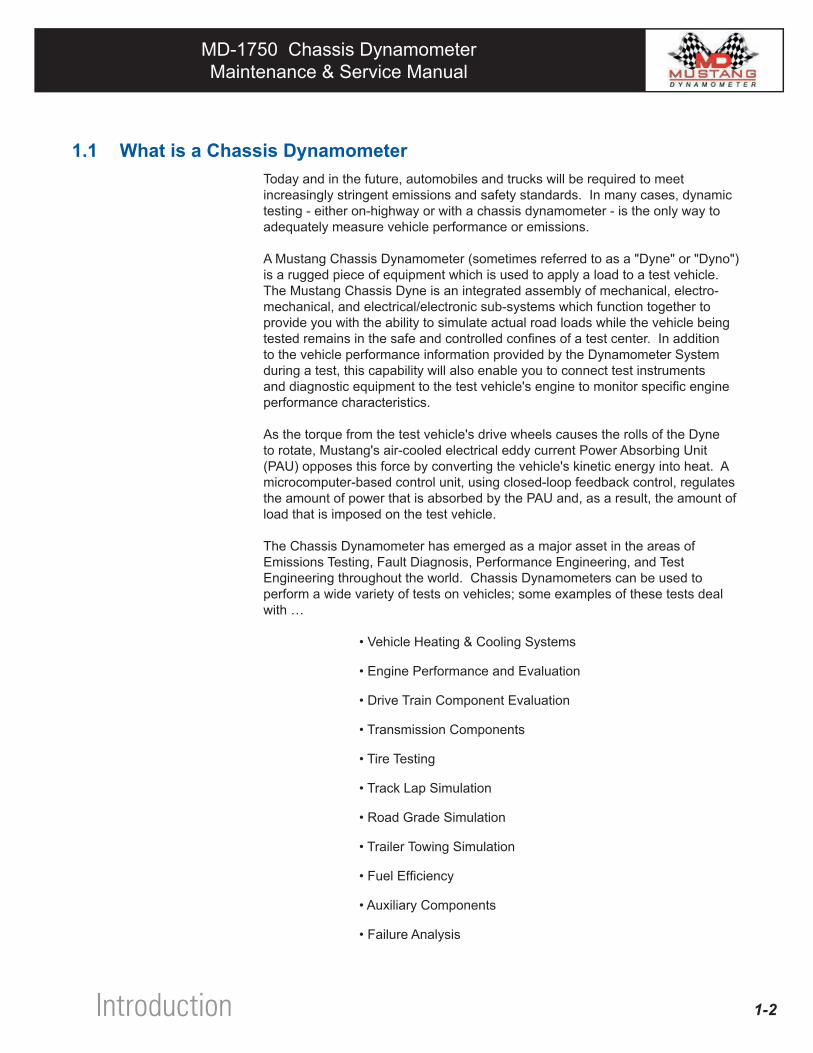
1.1 What is a Chassis DynamometerToday and in the future, automobiles and trucks will be required to meet increasingly stringent emissions and safety standards. In many cases, dynamic testing - either on-highway or with a chassis dynamometer - is the only way to adequately measure vehicle performance or emissions.
A Mustang Chassis Dynamometer (sometimes referred to as a "Dyne" or "Dyno") is a rugged piece of equipment which is used to apply a load to a test vehicle. The Mustang Chassis Dyne is an integrated assembly of mechanical, electro-mechanical, and electrical/electronic sub-systems which function together to provide you with the ability to simulate actual road loads while the vehicle being tested remains in the safe and controlled confines of a test center. In addition to the vehicle performance information provided by the Dynamometer System during a test, this capability will also enable you to connect test instruments and diagnostic equipment to the test vehicle's engine to monitor specific engine performance characteristics.
As the torque from the test vehicle's drive wheels causes the rolls of the Dyne to rotate, Mustang's air-cooled electrical eddy current Power Absorbing Unit (PAU) opposes this force by converting the vehicle's kinetic energy into heat. A microcomputer-based control unit, using closed-loop feedback control, regulates the amount of power that is absorbed by the PAU and, as a result, the amount of load that is imposed on the test vehicle.
The Chassis Dynamometer has emerged as a major asset in the areas of Emissions Testing, Fault Diagnosis, Performance Engineering, and Test Engineering throughout the world. Chassis Dynamometers can be used to perform a wide variety of tests on vehicles; some examples of these tests deal with …
• Vehicle Heating & Cooling Systems
• Engine Performance and Evaluation
• Drive Train Component Evaluation
• Transmission Components
• Tire Testing
• Track Lap Simulation
• Road Grade Simulation
• Trailer Towing Simulation
• Fuel Efficiency
• Auxiliary Components
• Failure Analysis
1-2Introduction
MD-1750 Chassis DynamometerMaintenance & Service Manual
MD-1750 Chassis DynamometerMaintenance & Service Manual
1-3
1.2 About This ManualThis manual provides you with the information you will need to know when you want to install and perform routine maintenance as well as more complex service on your MD-1750 Chassis Dynamometer. The following sections are included in this manual:
Section 1 - Introduction This is the section you are currently reading.
Section 2 - The System This section presents a description of the MD-1750 Chassis Dynamometer System to familiarize you with its major components. In addition, the principles of dynamometer operation are discussed.
Section 3 - Safety First A number of very important safety tips are presented in this section. BE SURE TO STUDY THIS SECTION CAREFULLY!
Section 4 - Installation A step-by-step procedure is given in this section to help ensure that your Dyne is installed properly.
Section 5 - Operational Checkout A sequence of operational checks is provided in this section to verify that your system is operating properly.
Section 6 - Preventative Maintenance General maintenance and lubrication instructions are presented in this section.
Section 7 - Troubleshooting Some basic troubleshooting hints are contained in this section.
Section 8 - Appendices The appendices contain reference information that you can easily access when you need it.
Specifications General equipment specifications.
Introduction
MD-1750 Chassis DynamometerMaintenance & Service Manual
MD-1750 Chassis DynamometerMaintenance & Service Manual
1-4
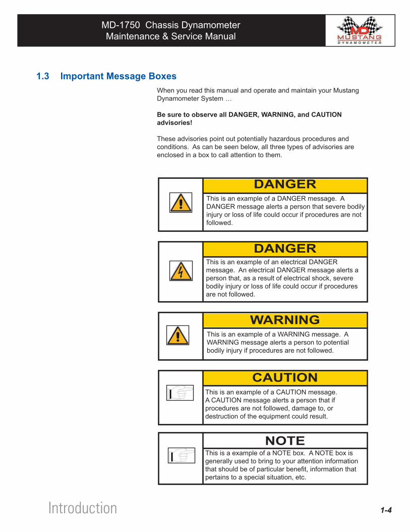
1.3 Important Message BoxesWhen you read this manual and operate and maintain your Mustang Dynamometer System …
Be sure to observe all DANGER, WARNING, and CAUTION advisories!
These advisories point out potentially hazardous procedures and conditions. As can be seen below, all three types of advisories are enclosed in a box to call attention to them.
This is an example of a DANGER message. A DANGER message alerts a person that severe bodily injury or loss of life could occur if procedures are not followed.
DANGER
Introduction
This is an example of an electrical DANGER message. An electrical DANGER message alerts a person that, as a result of electrical shock, severe bodily injury or loss of life could occur if procedures are not followed.
DANGER
This is an example of a WARNING message. A WARNING message alerts a person to potential bodily injury if procedures are not followed.
WARNING
CAUTION
NOTE
This is an example of a CAUTION message. A CAUTION message alerts a person that if procedures are not followed, damage to, or destruction of the equipment could result.
This is a example of a NOTE box. A NOTE box is generally used to bring to your attention information that should be of particular benefit, information that pertains to a special situation, etc.
MD-1750 Chassis DynamometerMaintenance & Service Manual
MD-1750 Chassis DynamometerMaintenance & Service Manual
1.4 Before You StartBefore attempting to operate your Dynamometer for normal usage, it is very important that…
• Your Dynamometer has been properly installed.
• Your Dynamometer has been properly maintained.
• Your Dynamometer has been properly calibrated. Please refer to the MD-7000 Software Manual - Chapter 6 Calibration.
• No unsafe conditions exist with your Dynamometer or your work site.
• All personnel who will be performing maintenance and service on your Dynamometer have read this manual in its entirety and understand all of the information presented.
1.5 If You Need HelpMuch effort has been extended to make this manual easy to work with as well as complete and accurate. However, if there is something that you do not understand or something that you have a question about, please feel free to contact a Mustang representative at …
MUSTANG DYNAMOMETER2300 Pinnacle Parkway
Twinsburg, Ohio 44087 USAPh: (330) 963-5400Fax: (330) 425-3310
1-5 Introduction
Section
MD-1750 Chassis DynamometerMaintenance & Service Manual
MD-1750 Chassis DynamometerMaintenance & Service Manual
CONTENTS
2.1 Introduction 2-2
2.2 Major System Components 2-2 2.2.1 Dynamometer 2-3 2.2.2 Control & Monitoring System 2-4 2.2.3 Software System 2-5
2.3 Principles Of Operation 2-6
LIST OF FIGURES
Fig. 2.1 Major Components of the Dynamometer Sub-system 2-3
Fig. 2.2 Major Components of the Control & Monitoring Sub-system (Part 1 of 2) 2-4
Fig. 2.3 Major Components of the Control & Monitoring Sub-system (Part 2 of 2) 2-5
SectionSection The System2
MD-1750 Chassis DynamometerMaintenance & Service Manual
MD-1750 Chassis DynamometerMaintenance & Service Manual
2.1 IntroductionThis section of the manual provides general information that will help you to develop a comprehensive understanding of your MD-1750 Dynamometer System. The following topics are covered in this section:
• Major System Components
• Principles of Operation
When learning to operate and/or maintain your new Dynamometer we strongly suggest that you take a few moments to familiarize yourself with the information presented in this section of the manual. Doing so will greatly help you to understand the information that is presented in other sections of this manual.
2.2 Major System ComponentsThe major components of a MD-1750 Dynamometer System can be grouped into the following categories which are discussed below:
• Dynamometer • Control & Monitoring System • Software System
2-2 The System
MD-1750 Chassis DynamometerMaintenance & Service Manual
MD-1750 Chassis DynamometerMaintenance & Service Manual
2-3
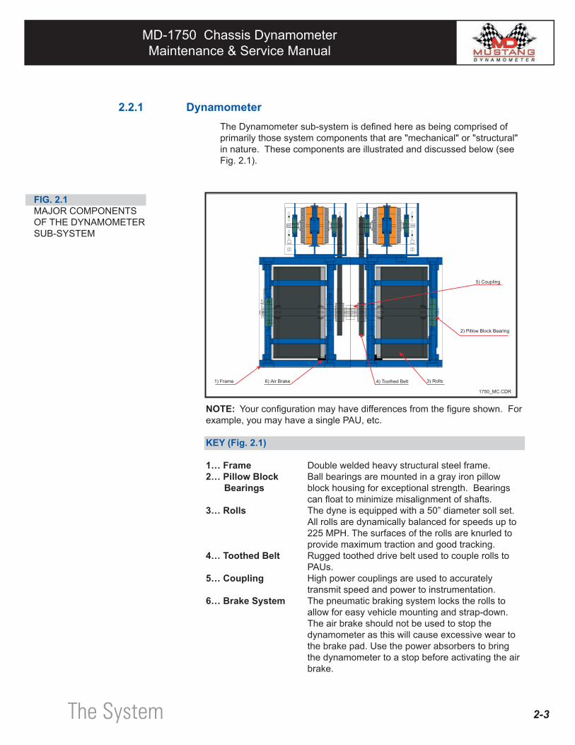
2.2.1 DynamometerThe Dynamometer sub-system is defined here as being comprised of primarily those system components that are "mechanical" or "structural" in nature. These components are illustrated and discussed below (see Fig. 2.1).
NOTE: Your configuration may have differences from the figure shown. For example, you may have a single PAU, etc.
KEY (Fig. 2.1)
1… Frame Double welded heavy structural steel frame.2… Pillow Block Ball bearings are mounted in a gray iron pillow Bearings block housing for exceptional strength. Bearings can float to minimize misalignment of shafts.3… Rolls The dyne is equipped with a 50” diameter soll set.
All rolls are dynamically balanced for speeds up to 225 MPH. The surfaces of the rolls are knurled to provide maximum traction and good tracking.
4… Toothed Belt Rugged toothed drive belt used to couple rolls to PAUs. 5… Coupling High power couplings are used to accurately transmit speed and power to instrumentation.6… Brake System The pneumatic braking system locks the rolls to
allow for easy vehicle mounting and strap-down. The air brake should not be used to stop the dynamometer as this will cause excessive wear to the brake pad. Use the power absorbers to bring the dynamometer to a stop before activating the air brake.
FIG. 2.1 MAJOR COMPONENTS OF THE DYNAMOMETER SUB-SYSTEM
The System
MD-1750 Chassis DynamometerMaintenance & Service Manual
MD-1750 Chassis DynamometerMaintenance & Service Manual
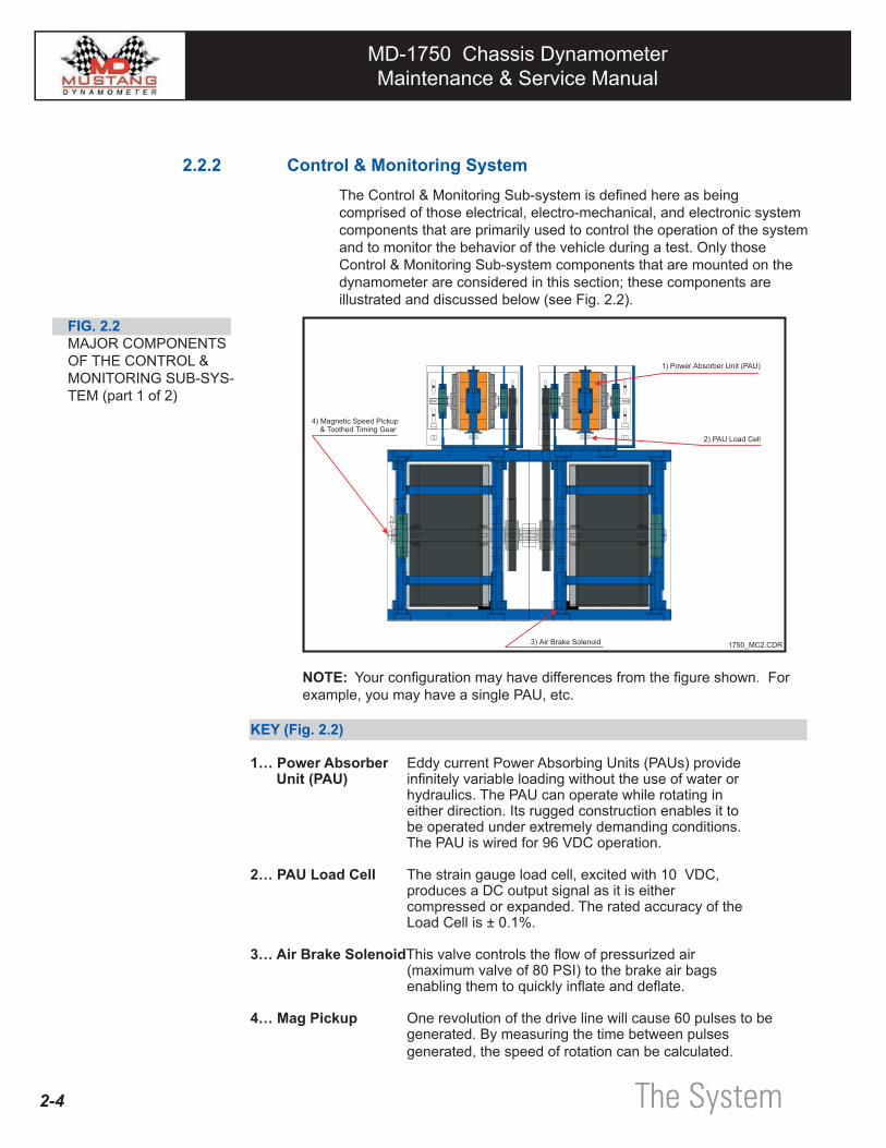
2.2.2 Control & Monitoring SystemThe Control & Monitoring Sub-system is defined here as being comprised of those electrical, electro-mechanical, and electronic system components that are primarily used to control the operation of the system and to monitor the behavior of the vehicle during a test. Only those Control & Monitoring Sub-system components that are mounted on the dynamometer are considered in this section; these components are illustrated and discussed below (see Fig. 2.2).
NOTE: Your configuration may have differences from the figure shown. For example, you may have a single PAU, etc.
KEY (Fig. 2.2)
1… Power Absorber Eddy current Power Absorbing Units (PAUs) provideUnit (PAU) infinitely variable loading without the use of water or hydraulics. The PAU can operate while rotating in either direction. Its rugged construction enables it to be operated under extremely demanding conditions. The PAU is wired for 96 VDC operation.
2… PAU Load Cell The strain gauge load cell, excited with 10 VDC, produces a DC output signal as it is either compressed or expanded. The rated accuracy of the Load Cell is ± 0.1%.
3… Air Brake SolenoidThis valve controls the flow of pressurized air (maximum valve of 80 PSI) to the brake air bags enabling them to quickly inflate and deflate.
4… Mag Pickup One revolution of the drive line will cause 60 pulses to be generated. By measuring the time between pulses generated, the speed of rotation can be calculated.
FIG. 2.2MAJOR COMPONENTS OF THE CONTROL & MONITORING SUB-SYS-TEM (part 1 of 2)
2-4 The System
MD-1750 Chassis DynamometerMaintenance & Service Manual
MD-1750 Chassis DynamometerMaintenance & Service Manual
2-5
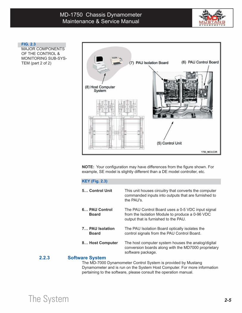
FIG. 2.3MAJOR COMPONENTS OF THE CONTROL & MONITORING SUB-SYS-TEM (part 2 of 2)
NOTE: Your configuration may have differences from the figure shown. For example, SE model is slightly different than a DE model controller, etc.
KEY (Fig. 2.3)
5… Control Unit This unit houses circuitry that converts the computer commanded inputs into outputs that are furnished to the PAU's.
6… PAU Control The PAU Control Board uses a 0-5 VDC input signalBoard from the Isolation Module to produce a 0-96 VDC output that is furnished to the PAU.
7… PAU Isolation The PAU Isolation Board optically isolates theBoard control signals from the PAU Control Board.
8… Host Computer The host computer system houses the analog/digital conversion boards along with the MD7000 proprietary software package.
2.2.3 Software SystemThe MD-7000 Dynamometer Control System is provided by Mustang Dynamometer and is run on the System Host Computer. For more information pertaining to the software, please consult the operation manual.
The System
MD-1750 Chassis DynamometerMaintenance & Service Manual
MD-1750 Chassis DynamometerMaintenance & Service Manual
2.3 Principles of OperationA Mustang Chassis Dynamometer will give you the ability to simulate actual road loads while the vehicle is stationery. This enables you to perform tests on a vehicle while test diagnostic instruments are connected to the vehicle's engine and exhaust system.
The Dynamometer consists primarily of drive roll set, a power absorbing unit(s) (PAU), a load cell(s), and a speed encoder.
During operation of the Dyne, the vehicle's drive wheels on top of the drive rolls. The vehicle's torque is transmitted through the drive rolls to the eddy-current Power Absorbing Unit (PAU). The PAU is belted directly in the dyne's drive line. It is prevented from "freely" rotating by the installation of a load cell. The "load" is measured by the load cell and is transmitted to the control system via an electrical signal. The PAU absorbs this load by energizing stationary electric field coils with a direct current. These coils establish magnetic fields through which the iron rotors of the PAU are rotated. This rotation generates eddy-currents in the rotors which produce a force that is counter to the direction of the rotary motion. The power absorbed by the PAU is dependent upon the amount of DC power applied to the field coils and the RPM of the spinning rotors. The speed of rotation of the rotors is measured by a magnetic device called a mag pickup and is transmitted to the control system.
When both torque (from the load cell signal) and speed (from the mag pickup signal) are known, horsepower can easily be determined.
2-6 The System
MD-1750 Chassis DynamometerMaintenance & Service Manual
MD-1750 Chassis DynamometerMaintenance & Service Manual
CONTENTS
3.1 Introduction 3-2
3.2 General Safety Issues 3-3 3.3 Operational Safety Issues 3-4
3.4 Maintenance Safety Issues 3-5
Section Safety First3
MD-1750 Chassis DynamometerMaintenance & Service Manual
MD-1750 Chassis DynamometerMaintenance & Service Manual
3.1 Introduction
Attention!Dynamometer operation is potentially dangerous. For your own safety, read and understand the following warnings before conducting any tests. If you cannot read English, or have difficulty understanding these warnings, please ask a super-visor or co-worker to explain them to you.
This equipment contains voltages which may be hazardous if contacted. Avoid contacting terminals, binding posts, and other exposed connections.
Throughout this manual you will encounter DANGER, WARNING, and CAUTION messages. These messages are intended to alert you to situations that are potentially dangerous to you or damaging to your machine. Please pay attention to these advisories and follow the directions given in them.
The safety messages presented below are categorized as follows: • General Safety Issues • Operational Safety Issues • Maintenance Safety Issues
The General Safety Issues apply whenever you are working with the dyne for any reason.
The Operational Safety Issues alert you to hazards that may arise during the operation of the dynamometer whether it is being operated for vehicle testing or during an operational checkout.
The Maintenance Safety Issues alert you to hazards that may arise when you are performing maintenance and service on your dynamometer system.
Please be sure to read and follow the directives in all of the safety messages given in this section.
3-2 Safety First
DANGER
DANGER
MD-1750 Chassis DynamometerMaintenance & Service Manual
MD-1750 Chassis DynamometerMaintenance & Service Manual
3-3
3.2 General Safety IssuesBe Knowledgeable … Do not attempt to operate, maintain or service your Chassis Dynamometer System until you have familiarized yourself with the equipment by reading the instructions in this manual.
Prepare Correctly … To avoid possible injury to personnel or damage to equipment do not apply power to your Dynamometer System until the following procedures have been satisfactorily completed: • Installation (Section 4) • Operational Checkout (Section 5)
Act Responsibly … Exercise caution and discretion when operating or performing maintenance on your dyne. Always observe typical, common sense test area precautions.
Beware of Projectiles … Tires that are rotating at high rates of speed can throw off stones and other projectiles. Wear approved safety glasses when in the vicinity of the vehicle being tested.
Protect Your Ears … Dynamometer noise can damage your hearing. Always wear approved ear protection when working near the dynamometer.
Beware of Being Grabbed … Keep limbs, hair, jewelry, and clothing away from the moving dynamometer rolls, belt, couplings, etc.
Cover Rolls … The rolls can move freely whenever the roll brake is not applied. Never walk on the rolls. Cover the rolls when the dynamometer is not in use.
Pay Attention … Maintain acute awareness when the dynamometer rolls are in motion.
Safety First
MD-1750 Chassis DynamometerMaintenance & Service Manual
MD-1750 Chassis DynamometerMaintenance & Service Manual
3-4
3.3 Operational Safety IssuesVent Engine Exhaust … Provide adequate room ventilation. High concentrations of engine exhaust can be deadly. Do not operate your Dynamometer without proper ventilation. The shop ventilation system should exchange 300 to 500 cubic feet of air per minute (500 cfm preferred).
Monitor Carbon Monoxide … Make sure you have installed a carbon monoxide monitor in the dynamometer bay.
Guarding … Provide floor markings and protective guard railings for customer/operator protection. NEVER operate your Dyne with any of its cover panels removed unless specifically directed to do so elsewhere in this manual.
Refresh Your Knowledge … Regularly review the operating procedures presented in this manual.
Keep Clear of Rolls … Stay away from the rolls when in operation.
Protect Eyes and Ears … Make sure that you wear proper eye and ear protection when operating the dyne.
Check Tires … Before driving the test vehicle onto the dyne, be sure to check the vehicle's tires for proper inflation. Inspect the tires for any signs of damage and remove any large embedded objects from the tread.
Restrain Vehicle Movement … During dynamometer operation it is common for the test vehicle to move laterally on the rolls. Also, unrestrained vehicles can launch off the dyne, causing death or serious injury.
To prevent personal injury and/or damage to the test vehicle, it is imperative that, prior to testing the vehicle, you secure the test vehicle in all directions (front, rear, and sides) with approved safety restraints that are bound to properly installed floor anchor pods.
Wheel Chocks … Use wheel chocks for the vehicle that is under test. Install one inch in front of non-driven wheels of test vehicle.
Proper Clearance … Always ensure that there is a clearance of at least four (4) feet to the front, rear, and sides of the dynamometer.
Stay Seated … The vehicle operator MUST remain in the driver's seat at all times during a drive-cycle test. DO NOT attempt to get in or out of the vehicle while the dynamometer rolls are moving.
If in Doubt, STOP! … Stop the equipment immediately if you have any doubt about the safe operating condition of the dynamometer and/or the correctness of any procedure that you are performing.
Safety First
MD-1750 Chassis DynamometerMaintenance & Service Manual
MD-1750 Chassis DynamometerMaintenance & Service Manual
3-5
3.4 Maintenance Safety IssuesElectrical Shock Hazard … Turn off electrical service to the system before performing any maintenance activity. Turn off the main breaker in your breaker box before working on anything related to the PAU.
No Jewelry … Before performing any electrical or mechanical trouble-shooting, repair, etc. on the dyne, it is highly advisable to remove any jewelry that you may be wearing..
Dyne Cover Panels … Use extreme caution around drive mechanisms and moving parts when operating the dyne with any of its cover panels removed from the chassis assembly.
Avoid Straining Yourself … Be careful when lifting dyne cover panels - they are very heavy. Be very careful when replacing belts, couplings, or bearings - the rolls are very heavy and can be difficult to handle.
Air Pressure … Make sure that there is no air pressure in the lines whenever you are working on the lift plates, roll brakes or air bags.
Watch Your Hands … Never put your hand between the roll brakes and roll when there is air hooked up to the system.
NEVER, NEVER, NEVER! … Never pull on the drive belt in order to spin the rolls.
Check Tightness … Make sure that all bolts on the Dyne are tight and all couplings are properly secured.
Safety First
MD-1750 Chassis DynamometerMaintenance & Service Manual
MD-1750 Chassis DynamometerMaintenance & Service Manual
CONTENTS
4.0 Introduction 4-2
4.1 Inspection 4-2
4.2 Tools & Equipment Needed For Installation 4-2
4.3 Shop Layout & Requirements 4-3
4.3.1 Pit Excavation (below-ground installation only) 4-3 4.3.2 Electrical 4-3 4.3.3 Pneumatic (Air) 4-3 4.3.4 Ventilation 4-3 4.3.5 Floor Anchors 4-4 4.3.6 Clearance 4-4
4.4 Above Ground Installation 4-4
4.5 Below Ground Installation 4-6
4.6 Control Installation 4-8
4.7 Pre-operational Inspection 4-12
LIST OF FIGURES
Fig. 4.1 Control System 4-8Fig. 4.2 Lift Solenoid 4-9Fig. 4.3 PAU Wiring 4-9Fig. 4.4 Computer Connections 4-10Fig. 4.5 Drive Control Box 4-11
Installation Section4
MD-1750 Chassis DynamometerMaintenance & Service Manual
MD-1750 Chassis DynamometerMaintenance & Service Manual
4-2
4.0 IntroductionThis section of the manual provides detailed instructions that you should follow when installing your new Chassis Dynamometer.
These instructions cover the installation of most Mustang models (i.e., standard & heavy-duty, uni- and bi-directional). Both in-ground and above-ground installations are covered as well as various methods of securing the dyne to the floor (ex. weld plates, stud anchors, anchor bolts).
4.1 Inspection
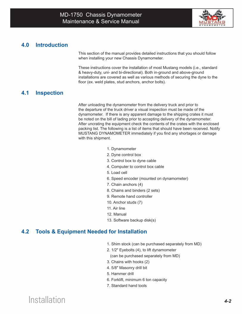
After unloading the dynamometer from the delivery truck and prior to the departure of the truck driver a visual inspection must be made of the dynamometer. If there is any apparent damage to the shipping crates it must be noted on the bill of lading prior to accepting delivery of the dynamometer. After uncrating the equipment check the contents of the crates with the enclosed packing list. The following is a list of items that should have been received. Notify MUSTANG DYNAMOMETER immediately if you find any shortages or damage with this shipment. 1. Dynamometer 2. Dyne control box 3. Control box to dyne cable 4. Computer to control box cable 5. Load cell 6. Speed encoder (mounted on dynamometer) 7. Chain anchors (4) 8. Chains and binders (2 sets) 9. Remote hand controller 10. Anchor studs (7) 11. Air line 12. Manual 13. Software backup disk(s)
4.2 Tools & Equipment Needed for Installation
1. Shim stock (can be purchased separately from MD) 2. 1/2" Eyebolts (4), to lift dynamometer (can be purchased separately from MD) 3. Chains with hooks (2) 4. 5/8" Masonry drill bit 5. Hammer drill 6. Forklift, minimum 6 ton capacity 7. Standard hand tools
Installation
MD-1750 Chassis DynamometerMaintenance & Service Manual
MD-1750 Chassis DynamometerMaintenance & Service Manual
4-3
4.3 Shop Layout & RequirementsThis section includes minimum requirements necessary to install the Dynamometer and to ensure safe operation. After determining which method of installation is best for you it is necessary to adhere to the following conditions.
4.3.1 Pit Excavation (Below-Ground Installation Only)
A below ground installation requires a floor opening of very specific dimensions. A drawing has been provided with your dynamometer depicting proper pit dimensions. It is recommended that you contract the services of a licensed contractor to perform the excavating of the dynamometer pit.
4.3.2 Electrical
A 110 volt AC, single phase, 15 amp circuit is required for the Host Computer System.
Your local electrical codes will determine how these circuits should be wired.
4.3.3 Pneumatic (Air)
The Dynamometer requires an air supply line to operate the lift and brake sys-tems. The airline should supply at least 80 psi but not more than 120 psi. An air dryer and regulator should be installed in the main supply line with the regulator set for 80 psi.
4.3.4 Ventilation
Your shop should be equipped with an effective ventilation system to direct tailpipe emissions to the outside air. Exhaust vents should be able to connect to all type of vehicles (front-wheel drive, rear wheel drive, dual exhaust, etc.)
The installer of the dynamometer accepts full responsibility for adhering to local, state and federal construction codes. The factory will not be held liable for damage or injury caused by improper installation.
WARNING
MD-100 230 VAC single phase, 60 Hz, 30 AmpsMD-250 230 VAC single phase, 60 Hz, 40 AmpsMD-750 230 VAC three phase, 60 Hz, 40 AmpsMD-1000 230 VAC three phase, 60 Hz, 40 AmpsMD-1750 single PAU 230 VAC, single phase, 60 Hz, 40 AmpsMD-1750 dual PAU 230 VAC, three phase, 60 Hz, 40 Amps
Dynamometer Electrical Service
Installation
MD-1750 Chassis DynamometerMaintenance & Service Manual
MD-1750 Chassis DynamometerMaintenance & Service Manual
4-4
4.3.5 FLOOR ANCHORS
It is common for vehicles to move laterally on the rollers during dynamometer op-eration. To prevent personal injury and damage to the vehicle it is imperative that the vehicle be secured with chains or straps. The dynamometer is supplied with 4 floor anchors that must be permanently installed as illustrated in the Appendix.
4.3.6 CLEARANCE
It is important to have enough room around the dynamometer to allow equipment to be moved around the service bay area. At least 18 feet clearance is needed in front of the dynamometer so that the vehicle under test has enough room to pull in the service bay.
There are two ways to install a Dynamometer, above ground or below ground. The following section describes both methods.
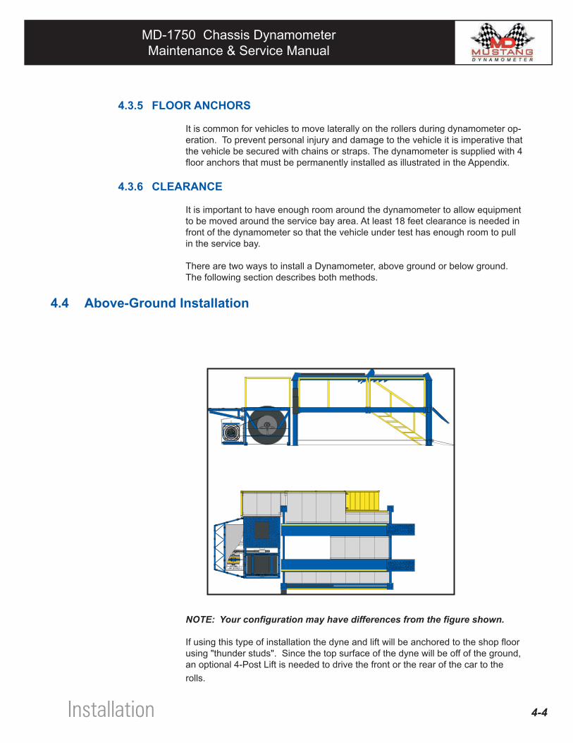
4.4 Above-Ground Installation
NOTE: Your configuration may have differences from the figure shown.
If using this type of installation the dyne and lift will be anchored to the shop floor using "thunder studs". Since the top surface of the dyne will be off of the ground, an optional 4-Post Lift is needed to drive the front or the rear of the car to the rolls.
Installation
MD-1750 Chassis DynamometerMaintenance & Service Manual
MD-1750 Chassis DynamometerMaintenance & Service Manual
4-5
Advantages • Less expensive type of installation • An existing shop requires little renovation • Easy to move dynamometer • 4-post lift can be used for other purposes when dyne is not in use. • Allows access to all points of the vehicle while on dyne
Disadvantages • Dynamometer and lift take up floor space • Not recommended for high speed testing
4.4.1 Above-Ground Installation Procedure (Dynamometer Only)
1. Remove rear PAU cover and side panels from the dynamometer.
2. Lift the dynamometer with a forklift and locate it in an appropriate location, keep in mind the clearance requirements discussed in the previous section.
3. Remove the lift plate opposite the retarder.
4. In the 7 anchor locations, drill 5/8" diameter holes 6" deep into the concrete. Ensure the holes are clear of dust and debris.
5. With the dynamometer in position, level the dynamometer using steel shim stock. If the dynamometer needs shims, place them underneath the dynamometer frame near the 7 anchor locations.
6. With the nut of the "Thunderstud" flush with the top of the stud, tap the "Thunderstuds" into the holes until the washer is flush with the dynamometer frame.
7. Expand the anchors by tightening the nut.
8. Re-install lift plates, torque bolts to 35 ft-lbs.
Please refer to 4-post lift operators manual for Lift installation procedures.
Installation
MD-1750 Chassis DynamometerMaintenance & Service Manual
MD-1750 Chassis DynamometerMaintenance & Service Manual
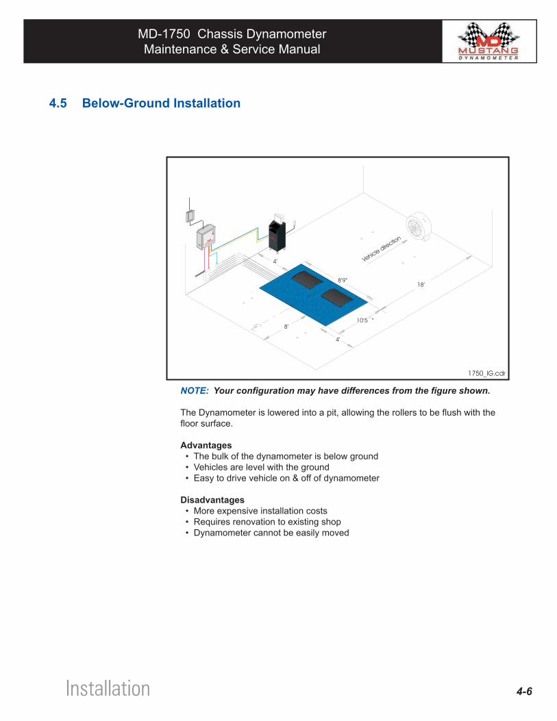
4.5 Below-Ground Installation
NOTE: Your configuration may have differences from the figure shown.
The Dynamometer is lowered into a pit, allowing the rollers to be flush with the floor surface.
Advantages • The bulk of the dynamometer is below ground • Vehicles are level with the ground • Easy to drive vehicle on & off of dynamometer
Disadvantages • More expensive installation costs • Requires renovation to existing shop • Dynamometer cannot be easily moved
4-6Installation
MD-1750 Chassis DynamometerMaintenance & Service Manual
MD-1750 Chassis DynamometerMaintenance & Service Manual
4-7
4.5.1 Below-Ground Installation Procedure
1. Check dynamometer pit and verify dimensions. Also, make sure the conduits are in the proper locations.
2. Clear the pit of all debris.
3. Remove cover plates from the dynamometer. Screw the 4 eyebolts into the holes along the main frame. Secure the chain to the eyebolts.
4. Lift the dynamometer evenly with the chain and lower it into the pit. There should be approximately 1/2" clearance between the frame and all walls of the pit.
5. Remove the lift plate opposite the retarder.
6. In the 7 anchor locations, drill 5/8" diameter holes 6" deep into the concrete. Ensure the holes are clear of dust and debris.
7. With the dynamometer in position, level the dynamometer using steel shim stock. If the dynamometer needs shims, place them underneath the dynamometer frame near the 7 anchor locations.
8. With the nut of the "Thunderstud" flush with the top of the stud, tap the "Thunderstuds" into the holes until the washer is flush with the dynamometer frame.
9. Expand the anchors by tightening the nut.
10. Re-install the lift plates, torque bolts to 35 ft-lbs.
Installation
MD-1750 Chassis DynamometerMaintenance & Service Manual
MD-1750 Chassis DynamometerMaintenance & Service Manual
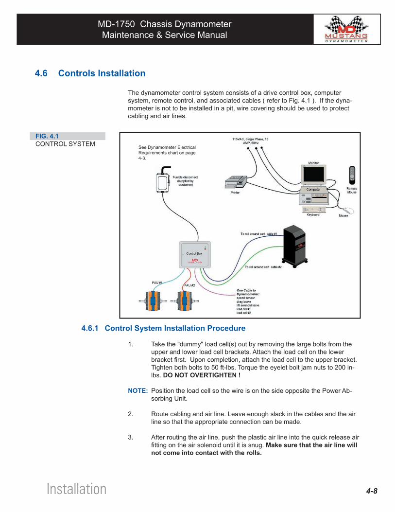
4.6 Controls Installation
The dynamometer control system consists of a drive control box, computer system, remote control, and associated cables ( refer to Fig. 4.1 ). If the dyna-mometer is not to be installed in a pit, wire covering should be used to protect cabling and air lines.
4.6.1 Control System Installation Procedure
1. Take the "dummy" load cell(s) out by removing the large bolts from the upper and lower load cell brackets. Attach the load cell on the lower bracket first. Upon completion, attach the load cell to the upper bracket. Tighten both bolts to 50 ft-lbs. Torque the eyelet bolt jam nuts to 200 in-lbs. DO NOT OVERTIGHTEN !
NOTE: Position the load cell so the wire is on the side opposite the Power Ab-sorbing Unit.
2. Route cabling and air line. Leave enough slack in the cables and the air line so that the appropriate connection can be made.
3. After routing the air line, push the plastic air line into the quick release air fitting on the air solenoid until it is snug. Make sure that the air line will not come into contact with the rolls.
4-8
FIG. 4.1CONTROL SYSTEM See Dynamometer Electrical
Requirements chart on page 4-3.
Installation
MD-1750 Chassis DynamometerMaintenance & Service Manual
MD-1750 Chassis DynamometerMaintenance & Service Manual
4-9
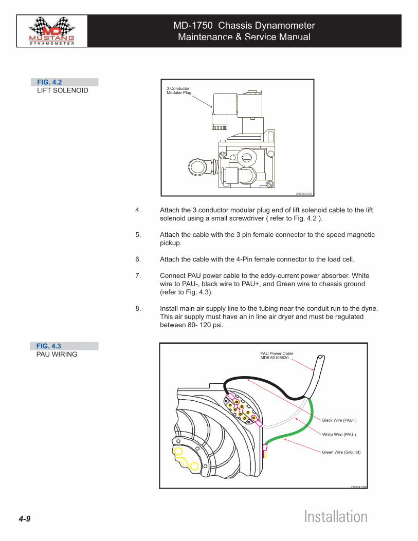
4. Attach the 3 conductor modular plug end of lift solenoid cable to the lift solenoid using a small screwdriver ( refer to Fig. 4.2 ).
5. Attach the cable with the 3 pin female connector to the speed magnetic pickup.
6. Attach the cable with the 4-Pin female connector to the load cell.
7. Connect PAU power cable to the eddy-current power absorber. White wire to PAU-, black wire to PAU+, and Green wire to chassis ground (refer to Fig. 4.3).
8. Install main air supply line to the tubing near the conduit run to the dyne. This air supply must have an in line air dryer and must be regulated between 80- 120 psi.
FIG. 4.3PAU WIRING
FIG. 4.2LIFT SOLENOID
MD-1750 Chassis Dynamometer - Installation
Installation
MD-1750 Chassis DynamometerMaintenance & Service Manual
MD-1750 Chassis DynamometerMaintenance & Service Manual
4-10
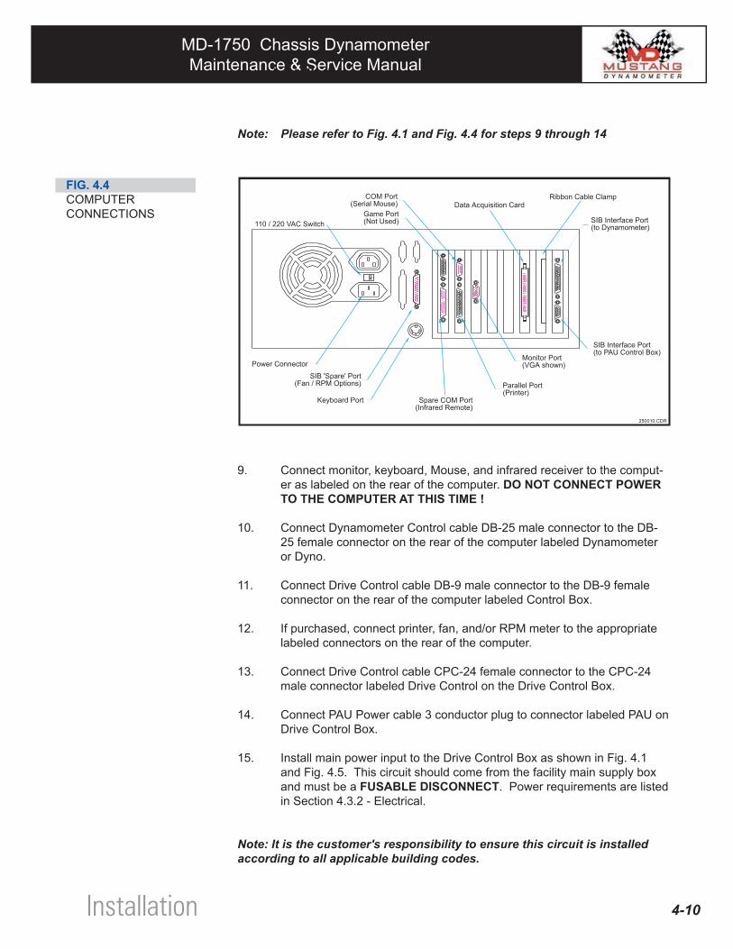
Note: Please refer to Fig. 4.1 and Fig. 4.4 for steps 9 through 14
FIG. 4.4COMPUTERCONNECTIONS
9. Connect monitor, keyboard, Mouse, and infrared receiver to the comput-er as labeled on the rear of the computer. DO NOT CONNECT POWER TO THE COMPUTER AT THIS TIME !
10. Connect Dynamometer Control cable DB-25 male connector to the DB-25 female connector on the rear of the computer labeled Dynamometer or Dyno.
11. Connect Drive Control cable DB-9 male connector to the DB-9 female connector on the rear of the computer labeled Control Box.
12. If purchased, connect printer, fan, and/or RPM meter to the appropriate labeled connectors on the rear of the computer.
13. Connect Drive Control cable CPC-24 female connector to the CPC-24 male connector labeled Drive Control on the Drive Control Box.
14. Connect PAU Power cable 3 conductor plug to connector labeled PAU on Drive Control Box.
15. Install main power input to the Drive Control Box as shown in Fig. 4.1 and Fig. 4.5. This circuit should come from the facility main supply box and must be a FUSABLE DISCONNECT. Power requirements are listed in Section 4.3.2 - Electrical.
Note: It is the customer's responsibility to ensure this circuit is installed according to all applicable building codes.
MD-1750 Chassis Dynamometer - Installation
Installation
MD-1750 Chassis DynamometerMaintenance & Service Manual
MD-1750 Chassis DynamometerMaintenance & Service Manual
4-11 Installation
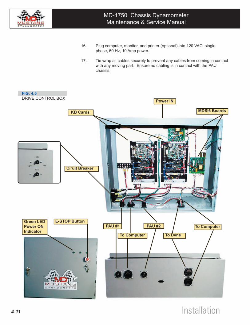
FIG. 4.5DRIVE CONTROL BOX
16. Plug computer, monitor, and printer (optional) into 120 VAC, single phase, 60 Hz, 10 Amp power.
17. Tie wrap all cables securely to prevent any cables from coming in contact with any moving part. Ensure no cabling is in contact with the PAU chassis.
E-STOP Button
Power IN
Green LEDPower ONIndicator
PAU #1 PAU #2
To Dyne
To Computer
To Computer
Ciruit Breaker
KB Cards MDSI6 Boards
MD-1750 Chassis DynamometerMaintenance & Service Manual
MD-1750 Chassis DynamometerMaintenance & Service Manual
4.7 Pre-Operational Inspection
WARNING: These procedures take at a minimum of 2 qualified personnel.
DO NOT PLUG THE SYSTEM INTO THE POWER SUPPLY. DO NOT TURN ON SYSTEM OR HAVE A VEHICLE ON DYNAMOMETER.
1. Verify the installation of the dynamometer meets all guidelines outlined in this manual. Do this NOW by reviewing the step by step installation procedures.
2. Verify the proper installation of the chain anchors.
3. Verify and check the torque of all the bolts and set screws to the speci-fications located in the Appendix. This procedure is very critical as some components may have loosened during shipping.
4. Verify all cable and air line connections are properly fastened, secured, and tightened.
5. Rotate dynamometer rollers by hand or foot ( a car should not be on at this time ) and verify they spin freely. The rollers will be somewhat difficult to spin due to the large mass that rotates.
6. Check to see that there is plenty of clearance around the rollers and that no components are rubbing, or are near rubbing.
7. Check all cabling and air lines to be sure that they are secured and clearly away from any rotating components.
8. Check the leveling of the dynamometer and ensure it is secured to the floor.
9. Clean up all installation tools in and around the dynamometer frame.
4-12Installation
MD-1750 Chassis DynamometerMaintenance & Service Manual
MD-1750 Chassis DynamometerMaintenance & Service Manual
CONTENTS
5.1 Introduction 5-2
5.2 Initial Start 5-2
Operational Checkout Section5
MD-1750 Chassis DynamometerMaintenance & Service Manual
MD-1750 Chassis DynamometerMaintenance & Service Manual
5-2
5.1 IntroductionAfter the dynamometer has been installed according to the instructions presented in Section 4 - Installation, you should perform the operational checkout procedure given in this section to verify that the dynamometer is operating properly.
5.2 Initial Start-up1. Be sure system is installed correctly as described in this manual.
2. Turn system ON with all components properly connected and linked to the computer. The system should boot up to the main menu screen.
WARNING: DO NOT DO ANY ADDITIONAL FUNCTIONS with the computer, stay in the main menu screen.
3. Verify the air lines are routed to the proper locations and that the pressure is set between 80 - 120 psi. The air supply must be regulated and dried. Turn air supply on and check for leaks.
WARNING: BE SURE ALL EQUIPMENT AND PERSONNEL ARE CLEAR OF DYNAMOMETER.
4. Activate the override roll lock switch on the side of the dyne control box. The rolls should lock.
5. Select a "REAR WHEEL DRIVE" vehicle for this Initial Start-up procedure. Check the vehicle crank case oil level, radiator level and automatic transmission fluid level (if applicable).
6. Ensure the vehicle tires are at their proper road pressure.
7. Be sure that there is no reason that the vehicle should not be operated on the dynamometer. If, for any reason, there are any doubts, DO NOT RUN THE DYNAMOMETER. Instead, please call a Mustang Dynamometer service engineer immediately.
8. Drive the vehicle onto the dynamometer. Be sure the vehicle is squared and centered on the rollers. If the vehicle is not squared and centered, drive off the dynamometer and repeat until the vehicle is squared and centered. Turn vehicle's engine off.
9. Unlock the rolls by turning the override switch on the side of the control box.
10. Start the vehicle, APPLY BRAKE, and put into a forward gear. SLOWLY release brake, or clutch if manual transmission, and rotate the tires very slowly (not to exceed 2 mph). After the vehicle is settled, apply brake, put vehicle into park, and turn engine off. This procedure should only take 10-15 seconds.
Operational Checkout
MD-1750 Chassis DynamometerMaintenance & Service Manual
MD-1750 Chassis DynamometerMaintenance & Service Manual
5-3
11. Make sure that the tires are clear of the dynamometer frame.
12. After the vehicle is positioned properly it is MANDATORY to secure the vehicle with straps.
13. Connect exhaust removal system.
14. Position the wheel chocks IN FRONT of the wheels that are not on the dynamometer.
15. The dynamometer is now ready for its first rotational break-in test.
WARNING: The computer should still be in the main menu screen.
16. Be sure all personnel and equipment are clear of the rotating dynamometer and that no personnel stand in front of the vehicle.
17. Start the engine and apply brake and/or clutch, place the vehicle in its drive gear or a low gear if a manual transmission.
18. Slowly release brake and/or clutch and check to see if the vehicle tires are rotating on the dynamometer. Do not exit your car, check with your assistant.
WARNING: DO NOT ACCELERATE VEHICLE: RUN AT IDLE. BE SURE ALL PERSONNEL ARE CLEAR OF VEHICLE.
19. Run vehicle for 2-3 minutes.
20. Listen for noises, feel and look for vibration. Be sure vehicle does not sway left/right or back/front. Check for anything unusual.
21. Be sure the driver stays in the vehicle and all personnel stay clear of the dynamometer and of the front of the vehicle.
22. If there are any apparent problems, stop the procedure immediately.
23. If no problem occurs, accelerate vehicle in 10 mph increments up to 50 mph for 2-3 minutes at each increment.
24. Repeat steps 22, 23, 24 as required.
25. After running vehicle for 2-3 minutes at 50 mph, slowly apply brake and bring the vehicle to a stop, and put into park.
26. Release and remove all straps and move wheel chocks from the vehicle.
27. Activate override switch on the side of the interface box to lock rolls. Be sure all personnel are clear. Rolls should be locked.
Operational Checkout
MD-1750 Chassis DynamometerMaintenance & Service Manual
MD-1750 Chassis DynamometerMaintenance & Service Manual
5-4
28. Be sure exhaust ventilation system is clear. Remove vehicle from dynamometer.
29. Verify and check the torque of all the bolts and set screws to the specifications located in the Appendix.
30. IF YOU HAVE ANY QUESTIONS, Please do not hesitate to call our factory at (330) 963-5400.
31. This completes the basic start up rotational test of the equipment.
Operational Checkout
CONTENTS
6.1 Introduction 6-3
6.2 General Information 6-3 6.2.1 Pillow Block Bearings 6-3 (A.) Expansion/Non-Expansion Bearings 6-3 (B.) Locking Bearing to Shaft 6-4 6.2.2 Gear Tooth Couplings 6-4 6.3 Preventative Maintenance Time Table 6-6
6.4 Lubrication 6-7 6.4.1 General Information 6-7 6.4.2 Pillow Block Bearings 6-8 6.4.3 Couplings 6-9 6.4.4 Power Absorber 6-11 6.5 Inspection & Adjustments 6-12
6.5.1 Check Torque of Bearing Set & Hold Down Screws 6-12 6.5.2 Check Torque of Coupling Set Screw 6-12 6.5.3 Check Condition of Coupling Key 6-12 6.5.4 Check for Roll Lock Brake Pad Wear 6-12 6.5.5 Check Condition & Tension of Belt 6-13 (A) Condition Check 6-13 (B) Tension Check 6-13 6.5.6 Power Absorbing Unit Checks 6-13 (A) Check Bearing End Play 6-14 (B) Check Rotor Air Gaps 6-14
6.6 Cleaning & Corrosion Prevention 6- 15
6.6.1 Cleaning Your Machine 6-15 6.6.2 Cleaning The Pit (If Applicable) 6-15 6.6.3 Corrosion Prevention 6-15
Preventative Maintenance Section6
LIST OF FIGURES
Fig. 6.1 Hub & Sleeve Gear Tooth Coupling 6-5Fig. 6.2 Hub & Flange Gear Tooth Coupling 6-5Fig. 6.3 Pillow Block Bearing Setscrews & Lube Point 6-8Fig. 6.4 Coupling Setscrews, Lube & Relief Points 6-10Fig. 6.5 PAU Lube & Relief Points 6-11Fig. 6.6 PAU Checking Nomenclature 6-14
LIST OF TABLES
Table 6.1 Preventative Maintenance Time Table 6-6Table 6.2 Suggested Lubrication Period (in Weeks) 6-9
Section Preventative Maintenance6
MD-1750 Chassis DynamometerMaintenance & Service Manual
MD-1750 Chassis DynamometerMaintenance & Service Manual
6-3
6.1 IntroductionProper maintenance procedures performed on a regular basis are essential to the well-being of any machine. By establishing a preventative maintenance program and then adhering to it you can lower the risk considerably of finding your dynamometer inoperative just when you need it the most.
This section begins with a general discussion of the following mechanical components of the dynamometer: • Pillow Block Bearings • Gear Tooth Couplings
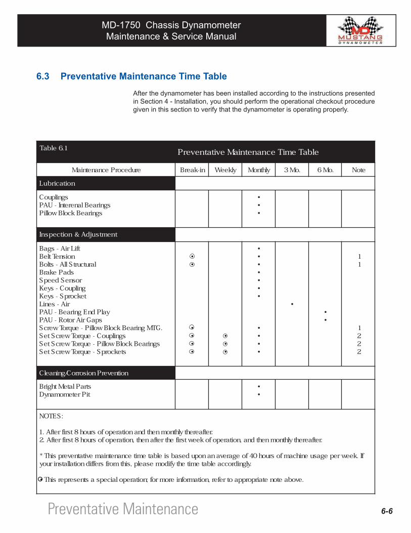
Later in this section a "Preventative Maintenance Time Table" is presented to give you an idea of the types of maintenance that will need to be performed and the frequency at which these activities should be performed. In addition, specific instructions are presented that provide more detailed maintenance information for various machine components.
6.2 General Information
6.2.1 Pillow Block Bearings
The Dynamometer's rolls, PAU, and inertia weight (optional) are supported by a combination of expansion and non-expansion types of both ball and high capacity double row spherical roller bearings
(A) Expansion/Non-Expansion Bearings
During the operation of your dynamometer, temperature changes may cause a linear expansion or contraction of the various components in the system. In a two pillow block arrangement (for example on a given roll), at least one non-expansion type of bearing is used as an anchor bearing to accommodate thrust loads and position peripheral equipment. The other pillow block may be of the expansion type to accommodate any expansion and contraction in the components. The bearings can be identified as follows:
Expansion-type bearings… are identified by a small white metal disk installed under the grease fitting on the bearing's housing.
Non-expansion bearings… will have either no disk under the fitting or a small blue metal disk under the fitting.
Preventative Maintenance
MD-1750 Chassis DynamometerMaintenance & Service Manual
MD-1750 Chassis DynamometerMaintenance & Service Manual
6-4
(B) Locking Bearing To Shaft
The inner race of each bearing is securely locked to the shaft on which they are mounted by means of two set screws in the bearing's collar.
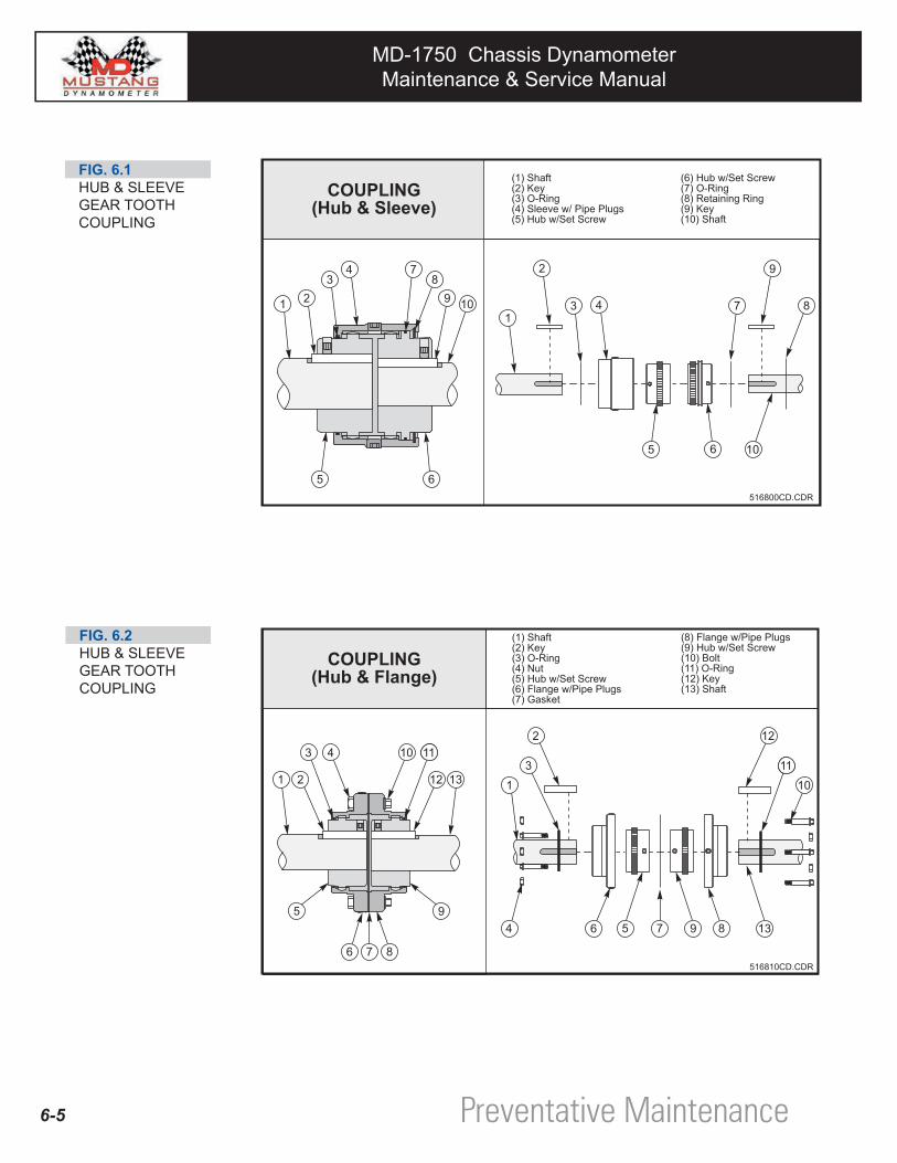
6.2.2 Gear Tooth Couplings
Gear Tooth Couplings are used in the drive line of your dynamometer between major sub-assemblies (ex. rolls, PAU, etc.) for the purposes of transmitting torque and enabling the sub-assemblies to be easily removed from the Dyne and al-lowing for slight offset and angular misalignment as well as end float in drive line components.
Two types of gear tooth couplings are used on Mustang Chassis Dynamometers: • Hub and Sleeve • Hub and Flange
The performance and life of couplings depend largely upon how you install and maintain them. Also, the correct installation, alignment, and lubrication of the couplings is critical to the proper operation of your dynamometer.
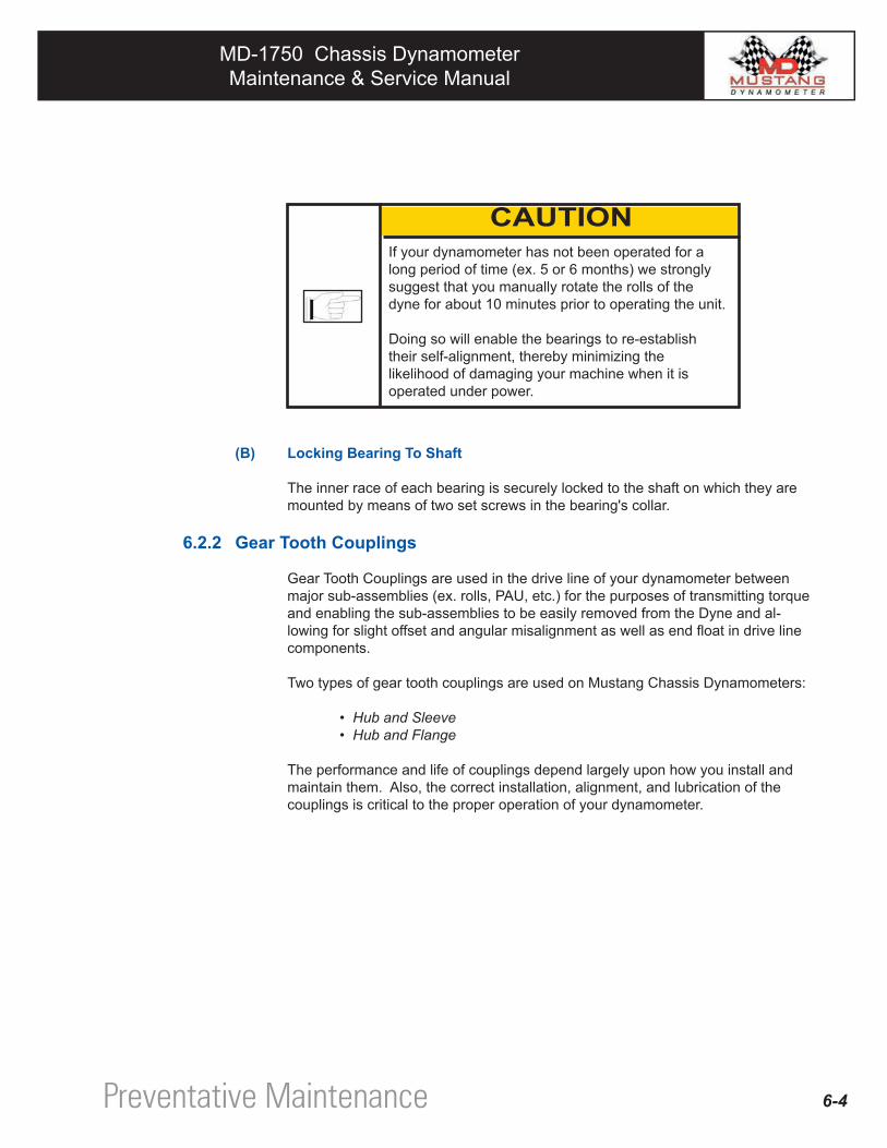
If your dynamometer has not been operated for a long period of time (ex. 5 or 6 months) we strongly suggest that you manually rotate the rolls of the dyne for about 10 minutes prior to operating the unit.
Doing so will enable the bearings to re-establish their self-alignment, thereby minimizing the likelihood of damaging your machine when it is operated under power.
Preventative Maintenance
CAUTION
MD-1750 Chassis DynamometerMaintenance & Service Manual
MD-1750 Chassis DynamometerMaintenance & Service Manual
6-5
FIG. 6.1HUB & SLEEVEGEAR TOOTHCOUPLING
FIG. 6.2HUB & SLEEVEGEAR TOOTHCOUPLING
Preventative Maintenance
MD-1750 Chassis DynamometerMaintenance & Service Manual
MD-1750 Chassis DynamometerMaintenance & Service Manual
6-6
6.3 Preventative Maintenance Time TableAfter the dynamometer has been installed according to the instructions presented in Section 4 - Installation, you should perform the operational checkout procedure given in this section to verify that the dynamometer is operating properly.
1.6elbaT elbaTemiTecnanetniaMevitatneverP
erudecorPecnanetniaM ni-kaerB ylkeeW ylhtnoM .oM3 .oM6 etoN
noitacirbuL
sgnilpuoCsgniraeBlaneretnI-UAP
sgniraeBkcolBwolliP
•••
tnemtsujdA&noitcepsnI
tfiLriA-sgaBnoisneTtleB
larutcurtSllA-stloBsdaPekarB
rosneSdeepSgnilpuoC-syeKtekcorpS-syeK
riA-seniLyalPdnEgniraeB-UAP
spaGriArotoR-UAP.GTMgniraeBkcolBwolliP-euqroTwercS
sgnilpuoC-euqroTwercSteSsgniraeBkcolBwolliP-euqroTwercSteS
stekcorpS-euqroTwercSteS
••
••••
•••
•••••••
••••
•••
11
1222
noitneverPnoisorroC/gninaelC
straPlateMthgirBtiPretemomanyD
••
:SETON
.retfaerehtylhtnomnehtdnanoitarepofosruoh8tsrifretfA.1.retfaerehtylhtnomnehtdna,noitarepofokeewtsrifehtretfaneht,noitarepofosruoh8tsrifretfA.2
fI.keewrepegasuenihcamfosruoh04foegarevananopudesabsielbatemitecnanetniamevitatneverpsihT*.ylgnidroccaelbatemitehtyfidomesaelp,sihtmorfsreffidnoitallatsniruoy
.evobaetonetairporppaotrefer,noitamrofnieromrof;noitarepolaicepsastneserpersihT•
Preventative Maintenance
MD-1750 Chassis DynamometerMaintenance & Service Manual
MD-1750 Chassis DynamometerMaintenance & Service Manual
6-7
6.4 Lubrication
6.4.1 GENERAL INFORMATION
Lubrication of the dyne's anti-friction bearings should be done as part of a planned maintenance schedule. The recommended lubrication interval given in the "Preventative Maintenance Time Table" should be used as a guide to establish this schedule.
Mixing lubricants is not recommended due to possible incompatibility. If you desire to change to other lubricants, follow all of the lubrication instructions provided in this manual and repeat lubrication a second time after 100 hours of service. Care must be taken to look for signs of incompatibility, such as extreme soupiness visible from grease relief areas.
A lack of lubricant as well as using the wrong kind will reduce the bearing's life expectancy.Your Mustang Dynamometer was lubricated at the factory using the lubricants specified in the chart in the Appendix - "Recom-mended Fluids".We strongly suggest that you continue to maintain your machine using these same lubricants.
Cleanliness is important in lubrication. Any grease used to lubricate the anti-friction bearings should be fresh and free from contamination. Similarly, care should be taken to properly clean all lubrication inlet areas (ex. zerk fittings, fill holes, etc.) to prevent lubricant contamination.
Preventative Maintenance
CAUTION
CAUTION
MD-1750 Chassis DynamometerMaintenance & Service Manual
MD-1750 Chassis DynamometerMaintenance & Service Manual
6-8
6.4.2 Pillow Block Bearing
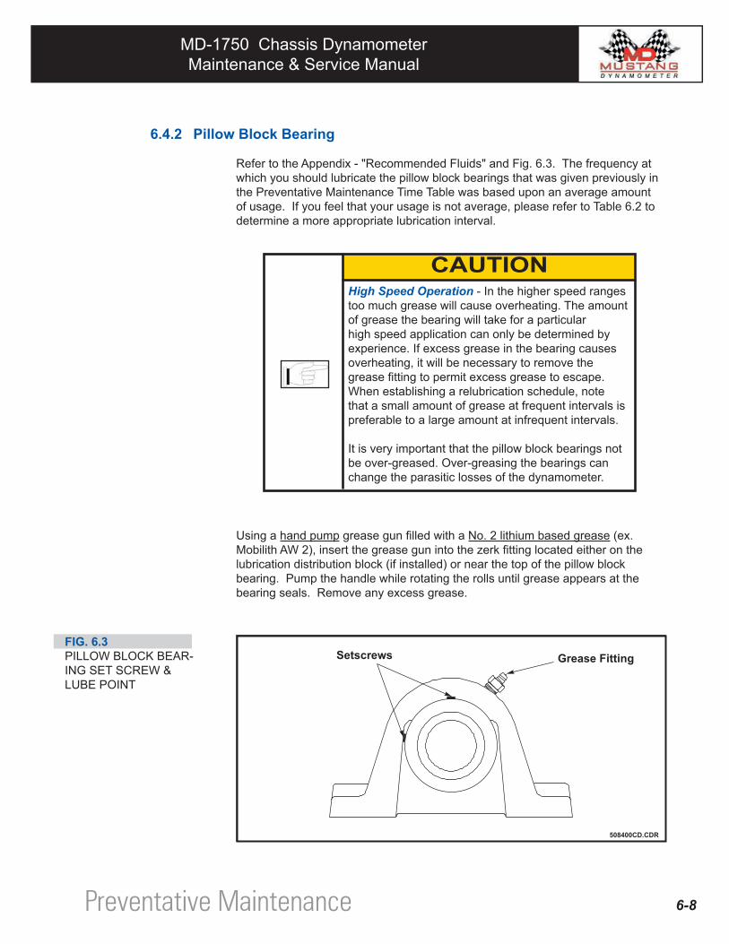
Refer to the Appendix - "Recommended Fluids" and Fig. 6.3. The frequency at which you should lubricate the pillow block bearings that was given previously in the Preventative Maintenance Time Table was based upon an average amount of usage. If you feel that your usage is not average, please refer to Table 6.2 to determine a more appropriate lubrication interval.
Using a hand pump grease gun filled with a No. 2 lithium based grease (ex. Mobilith AW 2), insert the grease gun into the zerk fitting located either on the lubrication distribution block (if installed) or near the top of the pillow block bearing. Pump the handle while rotating the rolls until grease appears at the bearing seals. Remove any excess grease.
High Speed Operation - In the higher speed ranges too much grease will cause overheating. The amount of grease the bearing will take for a particular high speed application can only be determined by experience. If excess grease in the bearing causes overheating, it will be necessary to remove the grease fitting to permit excess grease to escape. When establishing a relubrication schedule, note that a small amount of grease at frequent intervals is preferable to a large amount at infrequent intervals.
It is very important that the pillow block bearings not be over-greased. Over-greasing the bearings can change the parasitic losses of the dynamometer.
FIG. 6.3PILLOW BLOCK BEAR-ING SET SCREW & LUBE POINT
Preventative Maintenance
CAUTION
MD-1750 Chassis DynamometerMaintenance & Service Manual
MD-1750 Chassis DynamometerMaintenance & Service Manual
2.6elbaT )skeewni(doirePnoitacirbuLdetsegguS
)MPR(egnaRgnitarepOlacipyT
sruoHyaDrePnuR
1ot052
152ot005
105ot057
157ot
0001
ot10010051
ot10510002
ot10020052
ot10520003
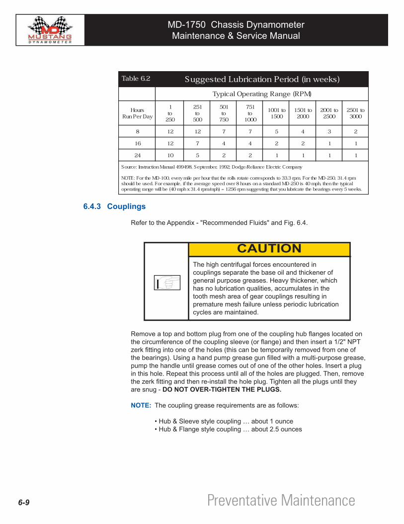
8 21 21 7 7 5 4 3 2
61 21 7 4 4 2 2 1 1
42 01 5 2 2 1 1 1 1
ynapmoCcirtcelEecnaileR/egdoD;2991,rebmetpeS,894994launaMnoitcurtsnI:ecruoS
mpr4.13,052-DMehtroF.mpr3.33otsdnopserrocetatorsllorehttahtruohrepelimyreve,001-DMehtroF:ETONlacipytehtneht,hpm04si052-DMdradnatsanosruoh8revodeepsegarevaehtfi,elpmaxeroF.desuebdluohs
.skeew5yrevesgniraebehtetacirbuluoytahtgnitseggusmpr6521=)hpm/mpr4.13xhpm04(eblliwegnargnitarepo
6.4.3 Couplings
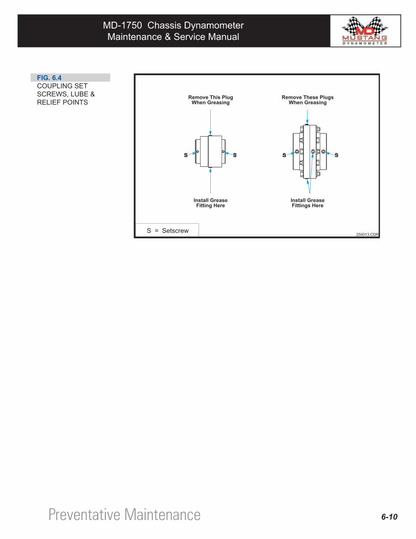
Refer to the Appendix - "Recommended Fluids" and Fig. 6.4.
Remove a top and bottom plug from one of the coupling hub flanges located on the circumference of the coupling sleeve (or flange) and then insert a 1/2" NPT zerk fitting into one of the holes (this can be temporarily removed from one of the bearings). Using a hand pump grease gun filled with a multi-purpose grease, pump the handle until grease comes out of one of the other holes. Insert a plug in this hole. Repeat this process until all of the holes are plugged. Then, remove the zerk fitting and then re-install the hole plug. Tighten all the plugs until they are snug - DO NOT OVER-TIGHTEN THE PLUGS.
NOTE: The coupling grease requirements are as follows:
• Hub & Sleeve style coupling … about 1 ounce • Hub & Flange style coupling … about 2.5 ounces
The high centrifugal forces encountered in couplings separate the base oil and thickener of general purpose greases. Heavy thickener, which has no lubrication qualities, accumulates in the tooth mesh area of gear couplings resulting in premature mesh failure unless periodic lubrication cycles are maintained.
6-9 Preventative Maintenance
CAUTION
MD-1750 Chassis DynamometerMaintenance & Service Manual
MD-1750 Chassis DynamometerMaintenance & Service Manual
FIG. 6.4COUPLING SET SCREWS, LUBE & RELIEF POINTS
6-10Preventative Maintenance
MD-1750 Chassis DynamometerMaintenance & Service Manual
MD-1750 Chassis DynamometerMaintenance & Service Manual
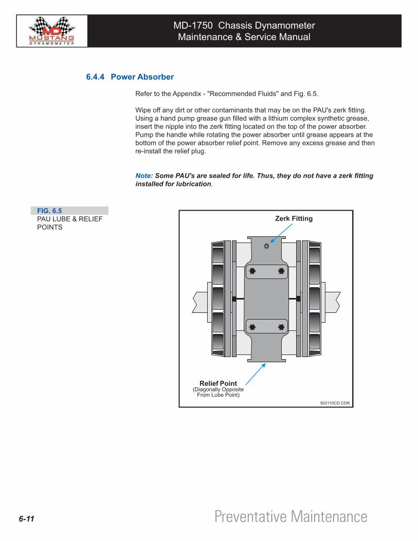
6.4.4 Power Absorber
Refer to the Appendix - "Recommended Fluids" and Fig. 6.5.
Wipe off any dirt or other contaminants that may be on the PAU's zerk fitting. Using a hand pump grease gun filled with a lithium complex synthetic grease, insert the nipple into the zerk fitting located on the top of the power absorber. Pump the handle while rotating the power absorber until grease appears at the bottom of the power absorber relief point. Remove any excess grease and then re-install the relief plug.
Note: Some PAU's are sealed for life. Thus, they do not have a zerk fitting installed for lubrication.
FIG. 6.5PAU LUBE & RELIEF POINTS
6-11 Preventative Maintenance
MD-1750 Chassis DynamometerMaintenance & Service Manual
MD-1750 Chassis DynamometerMaintenance & Service Manual
6.5 Inspection & Adjustments
6.5.1 Check Torque of Bearing Set & Hold Down Screws
Refer to the Appendix - "Torque Specifications" for appropriate torque values.
6.5.2 Check Torque of Coupling Set Screw
Refer to the Appendix - "Torque Specifications" for appropriate torque values.
6.5.3 Check Condition of Coupling Keys
Each coupling hub is prevented from rotating on its shaft by a square key (either 3/8" or 1/2" square). For each coupling, determine if its key is worn by grabbing each of the corresponding coupled rolls and rotating them in opposite directions. If you observe an excessive amount of play, the key and/or the coupling hub may need to be replaced.
6.5.4 Check for Roll Lock Brake Pad Wear
You can check the roll lock brake pads for signs of wear and deterioration by first lowering the lift plate and then inspecting the brake pads. If the average brake pad thickness is less than 1/8" or any spot on the pad is less than 1/16" thick, the brake pad will have to be replaced.
Loctite® 262 has been used on all set screws. If you remove any set screws you must re-apply Loctite® 262 prior to reinstalling them.
Do not use an excessive amount of Loctite® 262 on a set screw; about 1/2 drop is usually sufficient to lock the set screw.
When performing this inspection, make sure that the air lift will not be accidentally raised.
After the lift has been lowered, we strongly suggest that you turn off the supply air to the dynamometer until after you have completed the inspection.
6-12Preventative Maintenance
CAUTION
WARNING
MD-1750 Chassis DynamometerMaintenance & Service Manual
MD-1750 Chassis DynamometerMaintenance & Service Manual
6-13
6.5.5 Check Condition & Tension of Belts
(A) Visual Check
Visually inspect the toothed drive belt to ensure that there are no signs of wear, damage, or deterioration.
(B) Tension Check
The tension applied to the belt that connects the rolls should be sufficient to prevent the belts from "jumping teeth" on the sprockets.
As a rule-of-thumb only, a properly tensioned belt can be rotated approxi-mately 45° when it is grasped and twisted at a point on the belt which is midway between the two sprockets.
Toothed drive belts (also called synchronous belts) are not to be tensioned as you would a V-belt or any other belt that depends upon friction to transmit the load. They should be installed with a snug fit, neither too taut or too loose. Excessive toothed belt tension can lead to increased belt and bearing wear.
6.5.6 Power Absorbing Unit Checks
When performing this inspection, make sure that the air lift will not be accidentally raised.
After the lift has been lowered, we strongly suggest that you turn off the supply air to the dynamometer until after you have completed the inspection.
Preventative Maintenance
CAUTION
WARNING
MD-1750 Chassis DynamometerMaintenance & Service Manual
MD-1750 Chassis DynamometerMaintenance & Service Manual
6-14
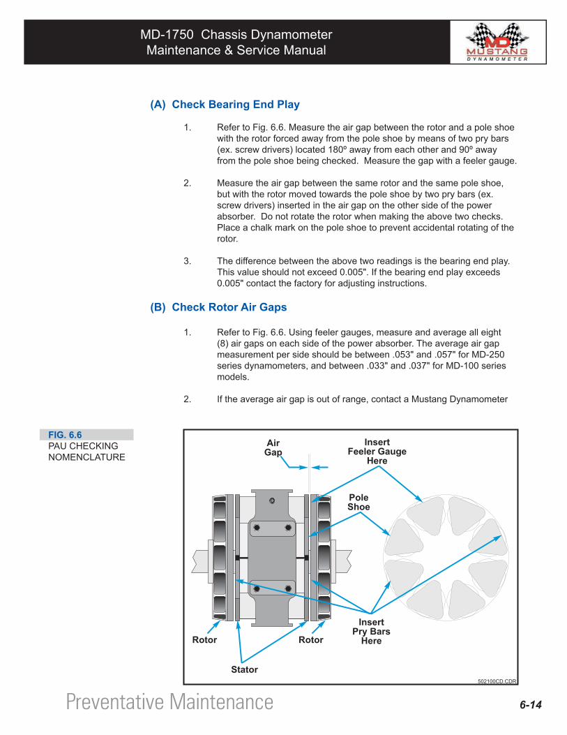
(A) Check Bearing End Play
1. Refer to Fig. 6.6. Measure the air gap between the rotor and a pole shoe with the rotor forced away from the pole shoe by means of two pry bars (ex. screw drivers) located 180º away from each other and 90º away from the pole shoe being checked. Measure the gap with a feeler gauge.
2. Measure the air gap between the same rotor and the same pole shoe, but with the rotor moved towards the pole shoe by two pry bars (ex. screw drivers) inserted in the air gap on the other side of the power absorber. Do not rotate the rotor when making the above two checks. Place a chalk mark on the pole shoe to prevent accidental rotating of the rotor.
3. The difference between the above two readings is the bearing end play. This value should not exceed 0.005". If the bearing end play exceeds 0.005" contact the factory for adjusting instructions.
(B) Check Rotor Air Gaps
1. Refer to Fig. 6.6. Using feeler gauges, measure and average all eight (8) air gaps on each side of the power absorber. The average air gap measurement per side should be between .053" and .057" for MD-250 series dynamometers, and between .033" and .037" for MD-100 series models.
2. If the average air gap is out of range, contact a Mustang Dynamometer
FIG. 6.6PAU CHECKING NOMENCLATURE
Preventative Maintenance
MD-1750 Chassis DynamometerMaintenance & Service Manual
MD-1750 Chassis DynamometerMaintenance & Service Manual
6-15
6.6 Cleaning & Corrosion Prevention
6.6.1 Cleaning Your Machine
When cleaning your machine you should only use a cloth that has been lightly wetted with either water or a mild grease/oil/tar remover. After cleaning bright metal parts be sure to apply a coating of corrosion preven-tative. For more information, please refer to the Appendix, "Recommended Fluids".
6.6.2 Cleaning The Pit (If Applicable)
The pit in which your dynamometer has been installed should be cleaned of all foreign objects and debris. A small paint scraper can be used to loosen any of the built-up dirt; a "shop vac" can be used to pick up any of the smaller debris. Any excessive grease that may have been thrown from moving parts should be wiped clean. Also make sure the drains are clear to avoid water from collecting and causing corrosion.
6.6.3 Corrossion Prevention
Refer to the Appendix - "Recommended Fluids".
After cleaning your machine, be sure to use an anti-corrosive spray on all exposed bare metal to prevent rusting or other forms of corrosion from damaging it.
You should never use pressurized water or compressed air to clean your machine since doing so may force contaminants into the machine's bearings.
Special attention should be paid to the air bags and the areas surrounding them since a built-up dirt here could cause wear which, in turn, could lead to premature air bag failure.
Preventative Maintenance
CAUTION
CAUTION
MD-1750 Chassis DynamometerMaintenance & Service Manual
MD-1750 Chassis DynamometerMaintenance & Service Manual
CONTENTS
7.1 Introduction 7-2
7.2 Troubleshooting Guide 7-3
Section Troubleshooting7
MD-1750 Chassis DynamometerMaintenance & Service Manual
MD-1750 Chassis DynamometerMaintenance & Service Manual
7.1 IntroductionThis section of the manual presents information and procedures that will be beneficial to you if you encounter a problem with your dynamometer.
The "Troubleshooting Guide" is provided to help you quickly diagnose and correct problems of a general nature that may arise.
If you encounter a problem with your dynamometer, please don't panic. Quite often "problems" are the result of something very minor such as forgetting to apply air pressure to the dyne or cables that are not connected. When you begin troubleshooting, if appropriate to the problem being observed, check the obvious first. If this does not correct the problem for you, then consult the information presented in this section of the manual. If you are still unable to correct the problem and you have exhausted all possibilities, please feel free to contact a Mustang Service Engineer.
7-2 Troubleshooting
MD-1750 Chassis DynamometerMaintenance & Service Manual
MD-1750 Chassis DynamometerMaintenance & Service Manual
7-3
7.2 Troubleshooting Guide
ediuGgnitoohselbuorT
teSlloR.I
melborP esuaCelbissoP noitcerroC
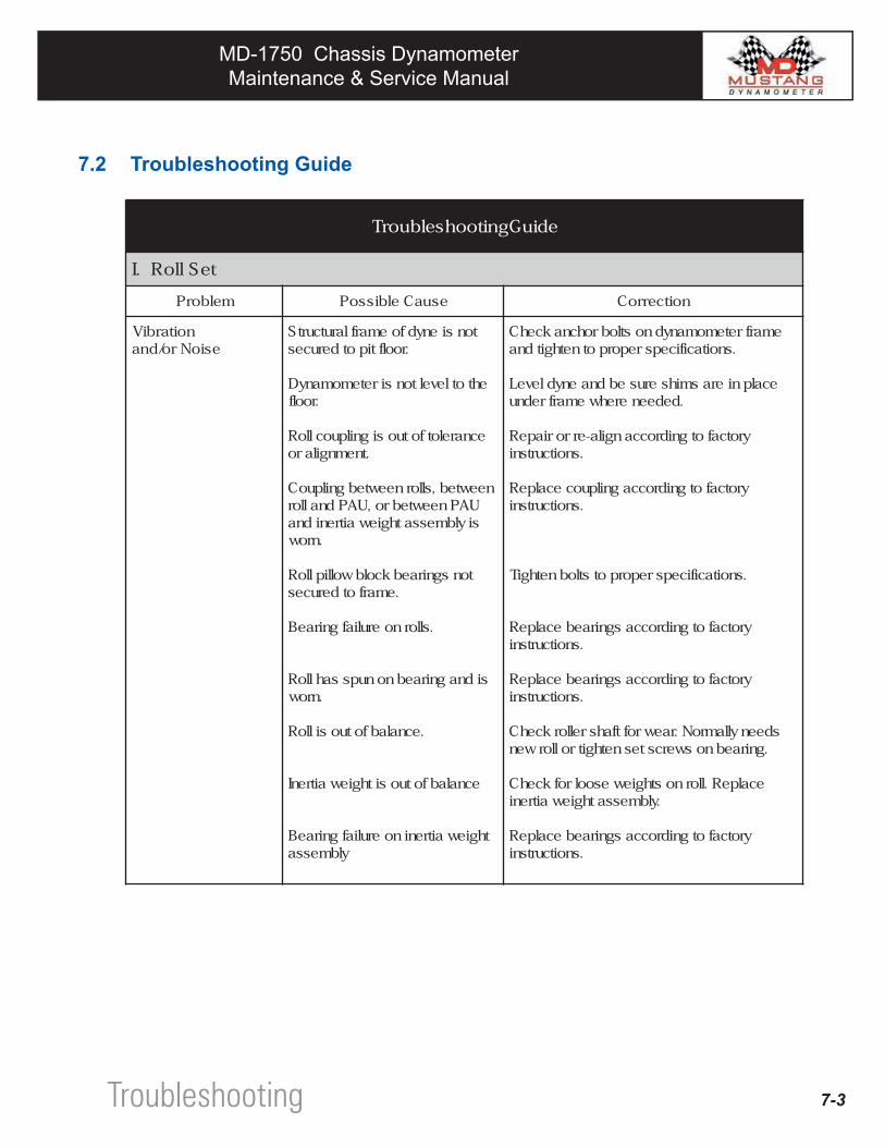
noitarbiVesioNro/dna
tonsienydfoemarflarutcurtS.roolftipotderuces
ehtotleveltonsiretemomanyD.roolf
ecnarelotfotuosignilpuoclloR.tnemngilaro
neewteb,sllorneewtebgnilpuoCUAPneewtebro,UAPdnallorsiylbmessathgiewaitrenidna
.nrow
tonsgniraebkcolbwolliplloR.emarfotderuces
.sllornoeruliafgniraeB
sidnagniraebnonupssahlloR.nrow
.ecnalabfotuosilloR
ecnalabfotuosithgiewaitrenI
thgiewaitreninoeruliafgniraeBylbmessa
emarfretemomanydnostlobrohcnakcehC.snoitacificepsreporpotnethgitdna
ecalpnierasmihserusebdnaenydleveL.dedeenerehwemarfrednu
yrotcafotgnidroccangila-erroriapeR.snoitcurtsni
yrotcafotgnidroccagnilpuocecalpeR.snoitcurtsni
.snoitacificepsreporpotstlobnethgiT
yrotcafotgnidroccasgniraebecalpeR.snoitcurtsni
yrotcafotgnidroccasgniraebecalpeR.snoitcurtsni
sdeenyllamroN.raewroftfahsrellorkcehC.gniraebnoswercstesnethgitrollorwen
ecalpeR.llornosthgiewesoolrofkcehC.ylbmessathgiewaitreni
yrotcafotgnidroccasgniraebecalpeR.snoitcurtsni
Troubleshooting
MD-1750 Chassis DynamometerMaintenance & Service Manual
MD-1750 Chassis DynamometerMaintenance & Service Manual
7-4
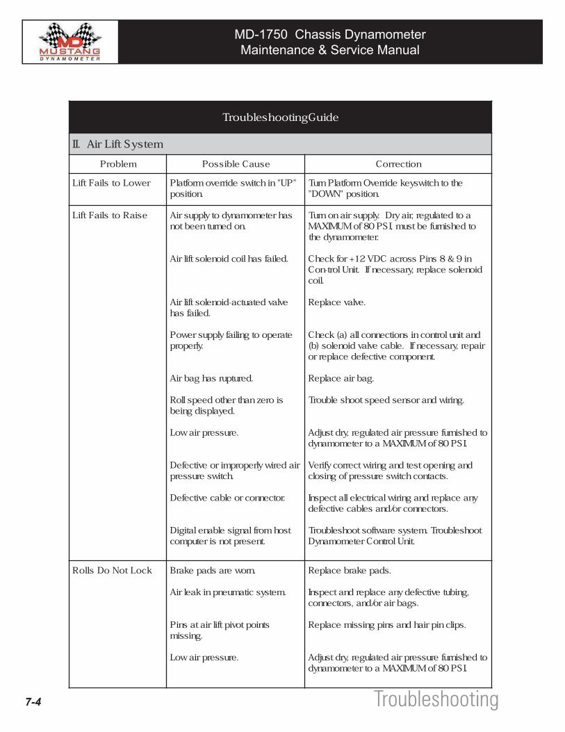
ediuGgnitoohselbuorT
metsyStfiLriA.II
melborP esuaCelbissoP noitcerroC
rewoLotsliaFtfiL "PU"nihctiwsedirrevomroftalP.noitisop
ehtothctiwsyekedirrevOmroftalPnruT.noitisop"NWOD"
esiaRotsliaFtfiL sahretemomanydotylppusriA.nodenrutneebton
.deliafsahliocdionelostfilriA
evlavdetautca-dionelostfilriA.deliafsah
etarepootgniliafylppusrewoP.ylreporp
.derutpursahgabriA
sioreznahtrehtodeepslloR.deyalpsidgnieb
.erusserpriawoL
riaderiwylreporpmiroevitcefeD.hctiwserusserp
.rotcennocroelbacevitcefeD
tsohmorflangiselbanelatigiD.tneserptonsiretupmoc
aotdetaluger,riayrD.ylppusrianonruTotdehsinrufebtsum,ISP08foMUMIXAM
.retemomanydeht
ni9&8sniPssorcaCDV21+rofkcehCdionelosecalper,yrassecenfI.tinUlort-noC
.lioc
.evlavecalpeR
dnatinulortnocnisnoitcennoclla)a(kcehCriaper,yrassecenfI.elbacevlavdionelos)b(
.tnenopmocevitcefedecalperro
.gabriaecalpeR
.gniriwdnarosnesdeepstoohselbuorT
otdehsinruferusserpriadetaluger,yrdtsujdA.ISP08foMUMIXAMaotretemomanyd
dnagninepotsetdnagniriwtcerrocyfireV.stcatnochctiwserusserpfognisolc
ynaecalperdnagniriwlacirtcelellatcepsnI.srotcennocro/dnaselbacevitcefed
toohselbuorT.metsyserawtfostoohselbuorT.tinUlortnoCretemomanyD
kcoLtoNoDslloR .nrowerasdapekarB
.metsyscitamuenpnikaelriA
stnioptoviptfilriatasniP.gnissim
.erusserpriawoL
.sdapekarbecalpeR
,gnibutevitcefedynaecalperdnatcepsnI.sgabriaro/dna,srotcennoc
.spilcnipriahdnasnipgnissimecalpeR
otdehsinruferusserpriadetaluger,yrdtsujdA.ISP08foMUMIXAMaotretemomanyd
Troubleshooting
MD-1750 Chassis DynamometerMaintenance & Service Manual
MD-1750 Chassis DynamometerMaintenance & Service Manual
7-5
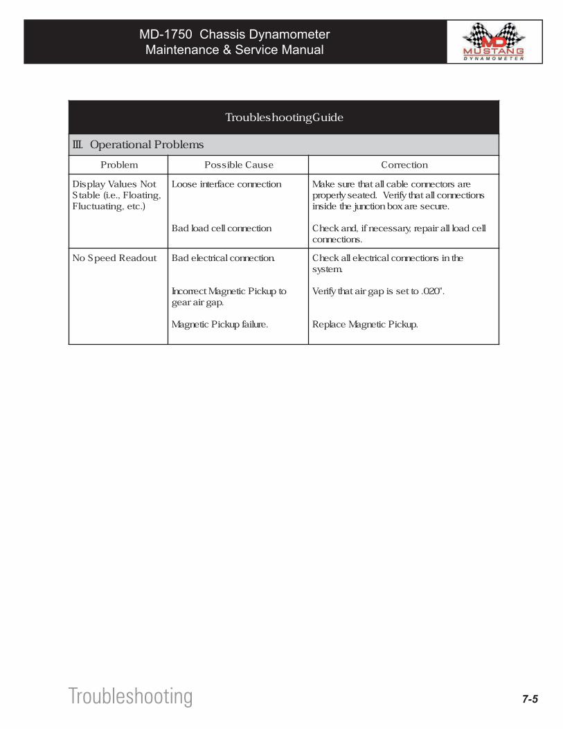
ediuGgnitoohselbuorT
smelborPlanoitarepO.III
melborP esuaCelbissoP noitcerroC
toNseulaVyalpsiD,gnitaolF,.e.i(elbatS
).cte,gnitautculF
noitcennocecafretniesooL
noitcennocllecdaoldaB
erasrotcennocelbacllatahterusekaMsnoitcennocllatahtyfireV.detaesylreporp
.eruceseraxobnoitcnujehtedisni
llecdaolllariaper,yrassecenfi,dnakcehC.snoitcennoc
tuodaeRdeepSoN .noitcennoclacirtceledaB
otpukciPcitengaMtcerrocnI.pagriaraeg
.eruliafpukciPcitengaM
ehtnisnoitcennoclacirtcelellakcehC.metsys
."020.ottessipagriatahtyfireV
.pukciPcitengaMecalpeR
Troubleshooting
MD-1750 Chassis DynamometerMaintenance & Service Manual
MD-1750 Chassis DynamometerMaintenance & Service Manual
CONTENTS
Appendix A - Torque Specifications
Appendix B - Recommended Fluids
Appendix C - Anchor Pod Installation - New Floors
Section8Appendix
MD-1750 Chassis DynamometerMaintenance & Service Manual
MD-1750 Chassis DynamometerMaintenance & Service Manual
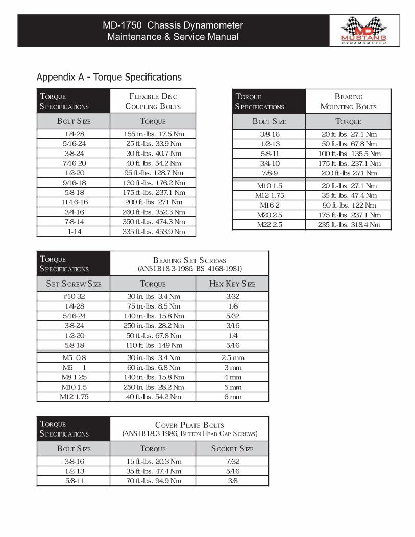
Appendix A - Torque Specifications
TORQUE
SPECIFICATIONS
BEARING SET SCREWS
ISNA( ,6891-3.81B SB )1891-8614
SET SCREW SIZE TORQUE HEX KEY SIZE
23-01# mN4.3.sbl-.ni03 23/3
82-4/1 mN5.8.sbl-.ni57 8/1
42-61/5 mN8.51.sbl-.ni041 23/5
42-8/3 mN2.82.sbl-.ni052 61/3
02-2/1 mN8.76.sbl-.tf05 4/1
81-8/5 mN941.sbl-.tf011 61/5
8.05M mN4.3.sbl-.ni03 mm5.2
16M mN8.6.sbl-.ni06 mm3
52.18M mN8.51.sbl-.ni041 mm4
5.101M mN2.82.sbl-.ni052 mm5
57.121M mN2.45.sbl-.tf04 mm6
TORQUE
SPECIFICATIONS
BEARING
MOUNTING BOLTS
BOLT SIZE TORQUE
61-8/3 mN1.72.sbl-.tf02
31-2/1 mN8.76.sbl-.tf05
11-8/5 mN5.531.sbl-.tf001
01-4/3 mN1.732.sbl-.tf571
9-8/7 mN172sbl-.tf002
5.101M mN1.72.sbl-.tf02
57.121M mN4.74.sbl-.tf53
261M mN221.sbl-.tf09
5.202M mN1.732.sbl-.tf571
5.222M mN4.813.sbl-.tf532
TORQUE
SPECIFICATIONS
FLEXIBLE DISC
COUPLING BOLTS
BOLT SIZE TORQUE
82-4/1 mN5.71.sbl-.ni551
42-61/5 mN9.33.sbl-.tf52
42-8/3 mN7.04.sbl-.tf03
02-61/7 mN2.45.sbl-.tf04
02-2/1 mN7.821.sbl-.tf59
81-61/9 mN2.671.sbl-.tf031
81-8/5 mN1.732.sbl-.tf571
61-61/11 mN172.sbl-.tf002
61-4/3 mN3.253.sbl-.tf062
41-8/7 mN3.474.sbl-.tf053
41-1 mN9.354.sbl-.tf533
TORQUE
SPECIFICATIONS
COVER PLATE BOLTS
ISNA( ,6891-3.81B BUTTON HEAD CAP SCREWS)
BOLT SIZE TORQUE SOCKET S IZE
61-8/3 mN3.02.sbl-.tf51 23/7
31-2/1 mN4.74.sbl-.tf53 61/5
11-8/5 mN9.49.sbl-.tf07 8/3
MD-1750 Chassis DynamometerMaintenance & Service Manual
MD-1750 Chassis DynamometerMaintenance & Service Manual
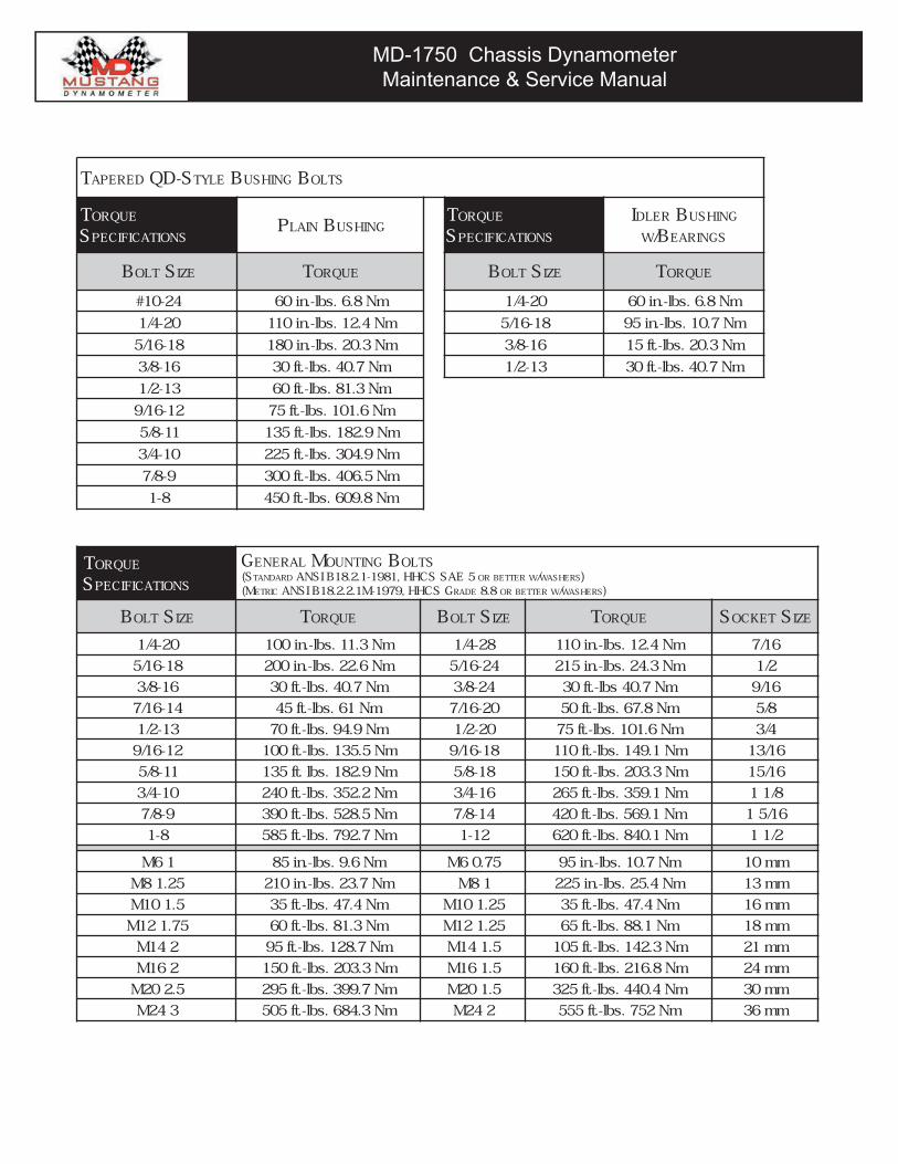
TAPERED S-DQ TYLE BUSHING BOLTS
TORQUE
SPECIFICATIONSPLAIN BUSHING
TORQUE
SPECIFICATIONS
IDLER BUSHING
WB/ EARINGS
BOLT SIZE TORQUE BOLT SIZE TORQUE
42-01# mN8.6.sbl-.ni06 02-4/1 mN8.6.sbl-.ni06
02-4/1 mN4.21.sbl-.ni011 81-61/5 mN7.01.sbl-.ni59
81-61/5 mN3.02.sbl-.ni081 61-8/3 mN3.02.sbl-.tf51
61-8/3 mN7.04.sbl-.tf03 31-2/1 mN7.04.sbl-.tf03
31-2/1 mN3.18.sbl-.tf06
21-61/9 mN6.101.sbl-.tf57
11-8/5 mN9.281.sbl-.tf531
01-4/3 mN9.403.sbl-.tf522
9-8/7 mN5.604.sbl-.tf003
8-1 mN8.906.sbl-.tf054
TORQUE
SPECIFICATIONS
GENERAL MOUNTING BOLTSS( TANDARD ISNA ,1891-1.2.81B SCHH EAS 5 OR BETTER W/WASHERS)M( ETRIC ISNA ,9791-M1.2.2.81B SCHH GRADE 8.8 OR BETTER W/WASHERS)
BOLT SIZE TORQUE BOLT SIZE TORQUE SOCKET S IZE
02-4/1 mN3.11.sbl-.ni001 82-4/1 mN4.21.sbl-.ni011 61/7
81-61/5 mN6.22.sbl-.ni002 42-61/5 mN3.42.sbl-.ni512 2/1
61-8/3 mN7.04.sbl-.tf03 42-8/3 mN7.04sbl-.tf03 61/9
41-61/7 mN16.sbl-.tf54 02-61/7 mN8.76.sbl-.tf05 8/5
31-2/1 mN9.49.sbl-.tf07 02-2/1 mN6.101.sbl-.tf57 4/3
21-61/9 mN5.531.sbl-.tf001 81-61/9 mN1.941.sbl-.tf011 61/31
11-8/5 mN9.281.sbl.tf531 81-8/5 mN3.302.sbl-.tf051 61/51
01-4/3 mN2.253.sbl-.tf042 61-4/3 mN1.953.sbl-.tf562 8/11
9-8/7 mN5.825.sbl-.tf093 41-8/7 mN1.965.sbl-.tf024 61/51
8-1 mN7.297.sbl-.tf585 21-1 mN1.048.sbl-.tf026 2/11
16M mN6.9.sbl-.ni58 57.06M mN7.01.sbl-.ni59 mm01
52.18M mN7.32.sbl-.ni012 18M mN4.52.sbl-.ni522 mm31
5.101M mN4.74.sbl-.tf53 52.101M mN4.74.sbl-.tf53 mm61
57.121M mN3.18.sbl-.tf06 52.121M mN1.88.sbl-.tf56 mm81
241M mN7.821.sbl-.tf59 5.141M mN3.241.sbl-.tf501 mm12
261M mN3.302.sbl-.tf051 5.161M mN8.612.sbl-.tf061 mm42
5.202M mN7.993.sbl-.tf592 5.102M mN4.044.sbl-.tf523 mm03
342M mN3.486.sbl-.tf505 242M mN257.sbl-.tf555 mm63
MD-1750 Chassis DynamometerMaintenance & Service Manual
MD-1750 Chassis DynamometerMaintenance & Service Manual
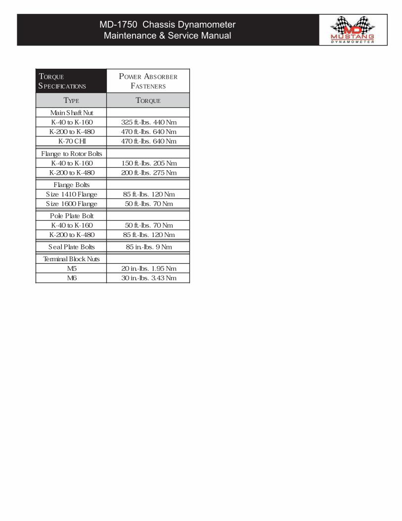
TORQUE
SPECIFICATIONS
POWER ABSORBER
FASTENERS
TYPE TORQUE
tuNtfahSniaM
061-Kot04-K mN044.sbl-.tf523
084-Kot002-K mN046.sbl-.tf074
IHC07-K mN046.sbl-.tf074
stloBrotoRotegnalF
061-Kot04-K mN502.sbl-.tf051
084-Kot002-K mN572.sbl-.tf002
stloBegnalF
egnalF0141eziS mN021.sbl-.tf58
egnalF0061eziS mN07.sbl-.tf05
tloBetalPeloP
061-Kot04-K mN07.sbl-.tf05
084-Kot002-K mN021.sbl-.tf58
stloBetalPlaeS mN9.sbl-.ni58
stuNkcolBlanimreT
5M mN59.1.sbl-.ni02
6M mN34.3.sbl-.ni03
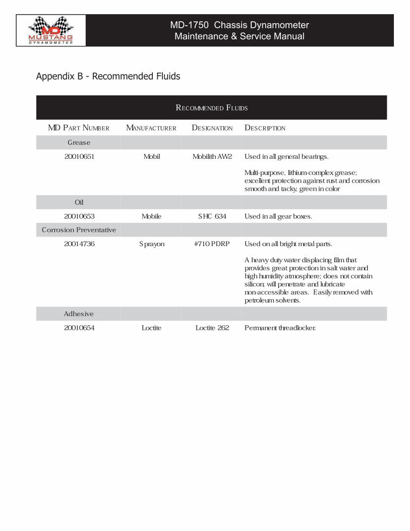
MD-1750 Chassis DynamometerMaintenance & Service Manual
MD-1750 Chassis DynamometerMaintenance & Service Manual
Appendix B - Recommended Fluids
RECOMMENDED FLUIDS
DM PART NUMBER MANUFACTURER DESIGNATION DESCRIPTION
esaerG
15601002 liboM 2WAhtiliboM .sgniraeblarenegllanidesU
;esaergxelpmoc-muihtil,esoprup-itluMnoisorrocdnatsurtsniaganoitcetorptnellecxe
rolocnineerg,ykcatdnahtooms
liO
35601002 eliboM 436CHS .sexobraegllanidesU
evitatneverPnoisorroC
63741002 noyarpS PRDP017# .straplatemthgirbllanodesU
tahtmlifgnicalpsidretawytudyvaehAdnaretawtlasninoitcetorptaergsedivorpniatnoctonseod;erehpsomtaytidimuhhgih
etacirbuldnaetarteneplliw;nocilishtiwdevomerylisaE.saeraelbissecca-non
.stnevlosmuelortep
evisehdA
45601002 etitcoL 262etitcoL .rekcoldaerhttnenamreP
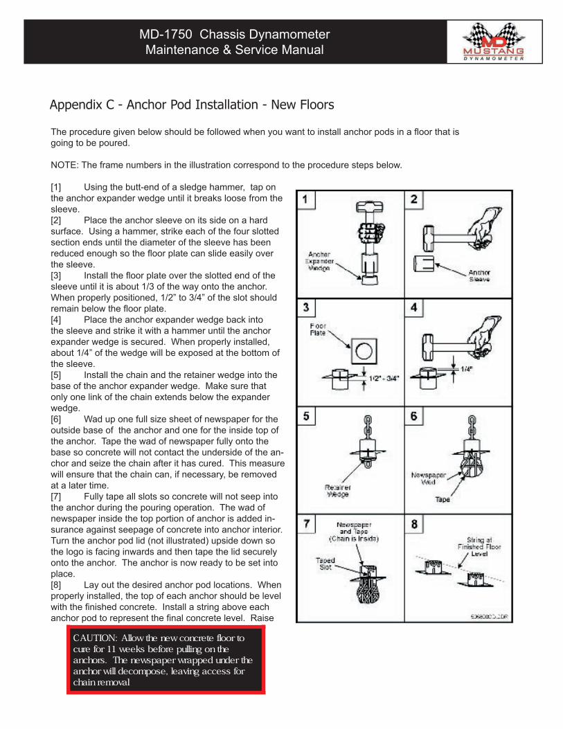
MD-1750 Chassis DynamometerMaintenance & Service Manual
MD-1750 Chassis DynamometerMaintenance & Service Manual
Appendix C - Anchor Pod Installation - New Floors
The procedure given below should be followed when you want to install anchor pods in a floor that is going to be poured.
NOTE: The frame numbers in the illustration correspond to the procedure steps below.
[1] Using the butt-end of a sledge hammer, tap on the anchor expander wedge until it breaks loose from the sleeve.[2] Place the anchor sleeve on its side on a hard surface. Using a hammer, strike each of the four slotted section ends until the diameter of the sleeve has been reduced enough so the floor plate can slide easily over the sleeve.[3] Install the floor plate over the slotted end of the sleeve until it is about 1/3 of the way onto the anchor. When properly positioned, 1/2” to 3/4” of the slot should remain below the floor plate. [4] Place the anchor expander wedge back into the sleeve and strike it with a hammer until the anchor expander wedge is secured. When properly installed, about 1/4” of the wedge will be exposed at the bottom of the sleeve.[5] Install the chain and the retainer wedge into the base of the anchor expander wedge. Make sure that only one link of the chain extends below the expander wedge. [6] Wad up one full size sheet of newspaper for the outside base of the anchor and one for the inside top of the anchor. Tape the wad of newspaper fully onto the base so concrete will not contact the underside of the an-chor and seize the chain after it has cured. This measure will ensure that the chain can, if necessary, be removed at a later time.[7] Fully tape all slots so concrete will not seep into the anchor during the pouring operation. The wad of newspaper inside the top portion of anchor is added in-surance against seepage of concrete into anchor interior. Turn the anchor pod lid (not illustrated) upside down so the logo is facing inwards and then tape the lid securely onto the anchor. The anchor is now ready to be set into place.[8] Lay out the desired anchor pod locations. When properly installed, the top of each anchor should be level with the finished concrete. Install a string above each anchor pod to represent the final concrete level. Raise
:NOITUAC otroolfetercnocwenehtwollAehtnognilluperofebskeew11roferuc
ehtrednudepparwrepapswenehT.srohcnarofsseccagnivael,esopmocedlliwrohcna
lavomerniahc
MD-1750 Chassis DynamometerMaintenance & Service Manual
MD-1750 Chassis DynamometerMaintenance & Service Manual
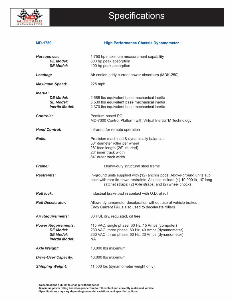
MD-1750 Chassis DynamometerMaintenance & Service Manual
MD-1750 Chassis DynamometerMaintenance & Service Manual
Specifications
• Specifications subject to change without notice• Maximum power rating based on proper tire to roll contact and correctly restrained vehicle• Specifications may vary depending on model variations and specified options.
MD-1750 High Performance Chassis Dynamometer
Horsepower: 1,750 hp maximum measurement capability DE Model: 800 hp peak absorption SE Model: 400 hp peak absorption
Loading: Air cooled eddy current power absorbers (MDK-250)
Maximum Speed: 225 mph
Inertia: DE Model: 2,688 lbs equivalent base mechanical inertia SE Model: 5,530 lbs equivalent base mechanical inertia Inertia Model: 2,370 lbs equivalent base mechanical inertia
Controls: Pentium-based PC MD-7000 Control Platform with Virtual InertiaTM Technology
Hand Control: Infrared, for remote operation
Rolls: Precision machined & dynamically balanced 50” diameter roller per wheel 28” face length (26” knurled) 28” inner track width 84” outer track width
Frame: Heavy-duty structural steel frame
Restraints: In-ground units supplied with (12) anchor pods. Above-ground units sup plied with rear tie-down restraints. All units include (4) 10,000 lb, 10’ long ratchet straps; (2) Axle straps; and (2) wheel chocks. Roll lock: Industrial brake pad in contact with O.D. of roll Roll Decelerator: Allows dynamometer deceleration without use of vehicle brakes Eddy Current PAUs also used to decelerate rollers
Air Requirements: 80 PSI, dry, regulated, oil free
Power Requirements: 115 VAC, single phase, 60 Hz, 15 Amps (computer) DE Model: 230 VAC, three phase, 60 Hz, 40 Amps (dynamometer) SE Model: 230 VAC, three phase, 60 Hz, 20 Amps (dynamometer) Inertia Model: NA
Axle Weight: 10,000 lbs maximum
Drive-Over Capacity: 10,000 lbs maximum
Shipping Weight: 11,500 lbs (dynamometer weight only)

2300 Pinnacle ParkwayTwinsburg, Ohio 44087 USA
Ph: (330) 963-5400Fax (330) 425-3310
www.mustangdyne.com