Embed Size (px)
Citation preview
Progress In Electromagnetics Research, PIER 66, 111–124, 2006
DESIGN OF WIDE-BAND DIELECTRIC RESONATORANTENNA WITH A TWO-SEGMENT STRUCTURE
P. Rezaei, M. Hakkak, and K. Forooraghi †
Faculty of EngineeringDepartment of Electrical EngineeringTarbiat Modares University (TMU)Tehran, Iran
Abstract—This paper discusses the analysis of a novel two-segmentrectangular dielectric resonator antenna (DRA) for broadening of theimpedance bandwidth. In the proposed configuration, two rectangulardielectric sections are used which are separated by a metal plate.With this configuration, it is possible to excite two adjacent resonantfrequencies. Utilizing the two-segment thin DRA and skillfully varyingits aspect ratio, an appropriate structure is obtained that illustratesmore than 76.8% impedance bandwidth (for S11>10 dB) at 3.32–7.46 GHz frequency band.
1. INTRODUCTION
The dielectric resonator (DR) is fabricated from low-loss dielectricmaterials. Its resonant frequencies are predominantly a function ofsize, shape, and material permittivity. DRs offer the advantages ofsmall size, lightweight, low profile, and low cost. They have beendemonstrated to be practical elements for antenna applications andhave several merits including high radiation efficiency, flexible feedarrangement, simple geometry, and compactness [1, 2].
The antenna applications of DRs were first proposed in theearly 1980’s [3]. Later, various investigations offered significantenhancements to parameters such as bandwidth, gain, polarization, orcoupling [4–7]. Over the last decades, various bandwidth enhancementtechniques have been developed for DRAs. These techniques wereclassified into three categories: Lowering the inherent Q-factor of the† The first and second authors are also with Iran Telecommunication Research Center(ITRC), Tehran, Iran.
112 Rezaei, Hakkak, and Forooraghi
resonator, using external matching networks and combine multipleDRs [4].
DRAs are commonly available in rectangular, cylindrical, andhemispherical geometries. Rectangular DRAs offer more designflexibility since two of the three of its dimensions can be variedindependently for a fixed resonant frequency and known dielectricconstant of the material [8].
In this paper, a two-segment rectangular dielectric section in asuitable arrangement is used to enhance the bandwidth of DRA. Thisstructure is composed of two rectangular sections with different (sizeand permittivity) which are separated by a perfect E plate [9].
Formerly, the overlap multi-segment DRA was developed toenhance coupling from the microstrip line [10, 11]. But the proposedarrangement emphasizes the bandwidth broadening and size reductionof the DRA.
The purpose of this investigation is to attempt to design DRAsthat are sufficiently compact and in addition have proper impedancebandwidth for use in broadband communications.
2. HALF VOLUME DRA
By using an extra metallic plate in a conventional DRA, which acts asan electric wall, the size of the DRA has been reduced approximatelyby half [12–16]. The added plate acts as a shorting post for theelectric field and allows part of the DRA to be removed, if certainfield symmetry exists. The use of the metal plate can be compared tothe shortening post used in patch antennas to reduce their length fromλ/2 to λ/4 [12].
Because of the symmetry of EM field distribution in the mainresonance frequency, we can divide the DRA into two halves with ametallic plate with zero thickness, perpendicular to the conductingground plane. The field distribution in the other half remainsunchanged in the main resonance case, and we can expect the resonantfrequency to remain the same. In this case the volume of the DRA iseffectively reduced by half. Greater reductions (as high as 75%) in thevolume of the DRA can also be obtained by utilizing sectored structures[17]. However, the feed setup (∆L) is expected to need alteration togive a good impedance match for the half volume design.
This is the base of our idea to obtain volume reduction and widebandwidth of operation. To this purpose we consider Figure 1.
What we are looking for, is a DRA that can offer different resonantfrequencies. The two half DRAs, due to their different permittivity andsize, resonate in two different frequencies. These two frequencies can
Progress In Electromagnetics Research, PIER 66, 2006 113
(a) (b)
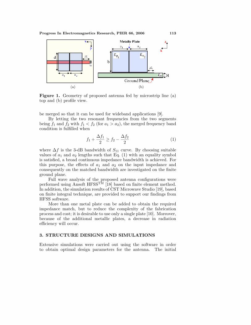
Figure 1. Geometry of proposed antenna fed by microstrip line (a)top and (b) profile view.
be merged so that it can be used for wideband applications [9].By letting the two resonant frequencies from the two segments
being f1 and f2 with f1 < f2 (for a1 > a2), the merged frequency bandcondition is fulfilled when
f1 +∆f1
2≥ f2 −
∆f2
2(1)
where ∆f is the 3-dB bandwidth of S11 curve. By choosing suitablevalues of a1 and a2 lengths such that Eq. (1) with an equality symbolis satisfied, a broad continuous impedance bandwidth is achieved. Forthis purpose, the effects of a1 and a2 on the input impedance andconsequently on the matched bandwidth are investigated on the finiteground plane.
Full wave analysis of the proposed antenna configurations wereperformed using Ansoft HFSSTM [18] based on finite element method.In addition, the simulation results of CST Microwave Studio [19], basedon finite integral technique, are provided to support our findings fromHFSS software.
More than one metal plate can be added to obtain the requiredimpedance match, but to reduce the complexity of the fabricationprocess and cost; it is desirable to use only a single plate [10]. Moreover,because of the additional metallic plates, a decrease in radiationefficiency will occur.
3. STRUCTURE DESIGNS AND SIMULATIONS
Extensive simulations were carried out using the software in orderto obtain optimal design parameters for the antenna. The initial
114 Rezaei, Hakkak, and Forooraghi
dimensions of the radiating portions of the antenna were determinedusing the equations developed for the dielectric waveguide model(DWM) for a rectangular resonator in free space [8].
Enforcing the magnetic wall boundary condition at the surfacesof the resonator, the following equations are obtained for the wave-numbers and the dominant mode resonance frequency:
k2x + k2
y + k2z = εrk
20 (2)
f0 =c
2π√
εr
√k2
x + k2y + k2
z (3)
where
kx =π
a, ky =
π
b, kztag(kzd/2) =
√(εr − 1)k2
0 − k2z (4)
where kx, ky, and kz denote the wave-numbers along the x, y, andz directions inside the DR, respectively. Then the appropriatedimensions of the antenna parameters were determined with trialoptimization.
In general, to achieve strong coupling, the DRA must be fabricatedfrom high permittivity materials. But, to operate over a widebandwidth, the DRA must have a low dielectric constant [1]. Previouswork has shown the critical coupling is possible for DRAs having ahigh value (20 or much) of dielectric constant [8]. The two segmentsare made of the same material with a dielectric constant of εr = 20.
3.1. Parametric Study
The microstrip feed-line is 1mm wide and on a 0.33 mm thick substratewith a relative dielectric constant, εs = 2.2, to give a characteristicimpedance of 50Ω. Open circuit microstrip line is considered to excitethe DR. To achieve the maximum coupling, the DRA is placed ata distance of λ/2 from the open end [8]. For this case the finestcoupling and consequently the maximum bandwidth for ∆L = 4.1 mmwas achieved.
The dimensions (a × d × b) of the proposed DRA are 10.5 mm ×6 mm × 9.6 mm that are equivalent to 0.192λ × 0.11λ × 0.176λ andλ is the free space wavelength at the center frequency of 5.5 GHz.Additionally, the proper lengths of the two segments (a1 and a2) areobtained 4.8 mm, and 5.7 mm respectively. The size of square groundplane is assumed to be 50 mm × 50 mm.
To compare the effects of variation in lengths of the two segments(a1 and a2), different arrangements of these lengths were evaluated.

Progress In Electromagnetics Research, PIER 66, 2006 115
Figure 2. Return loss of different arrangement of the two-segmentDRA.
For example, return loss for a1 and a2 (4.6 mm and 5.9 mm) and (5 mmand 5.5 mm) are shown in Figure 2, labeled as “arrangement 2” and“arrangement 3”, respectively.
Eq. (1) is satisfied in arrangement 1 and consequently widerimpedance bandwidth is realized in this case. In arrangement 2, due tocloseness of the two resonant frequencies, the impedance bandwidth islimited to 16.83%. Likewise, arrangement 3 has two separated bands,which offer 14.44% bandwidth totally.
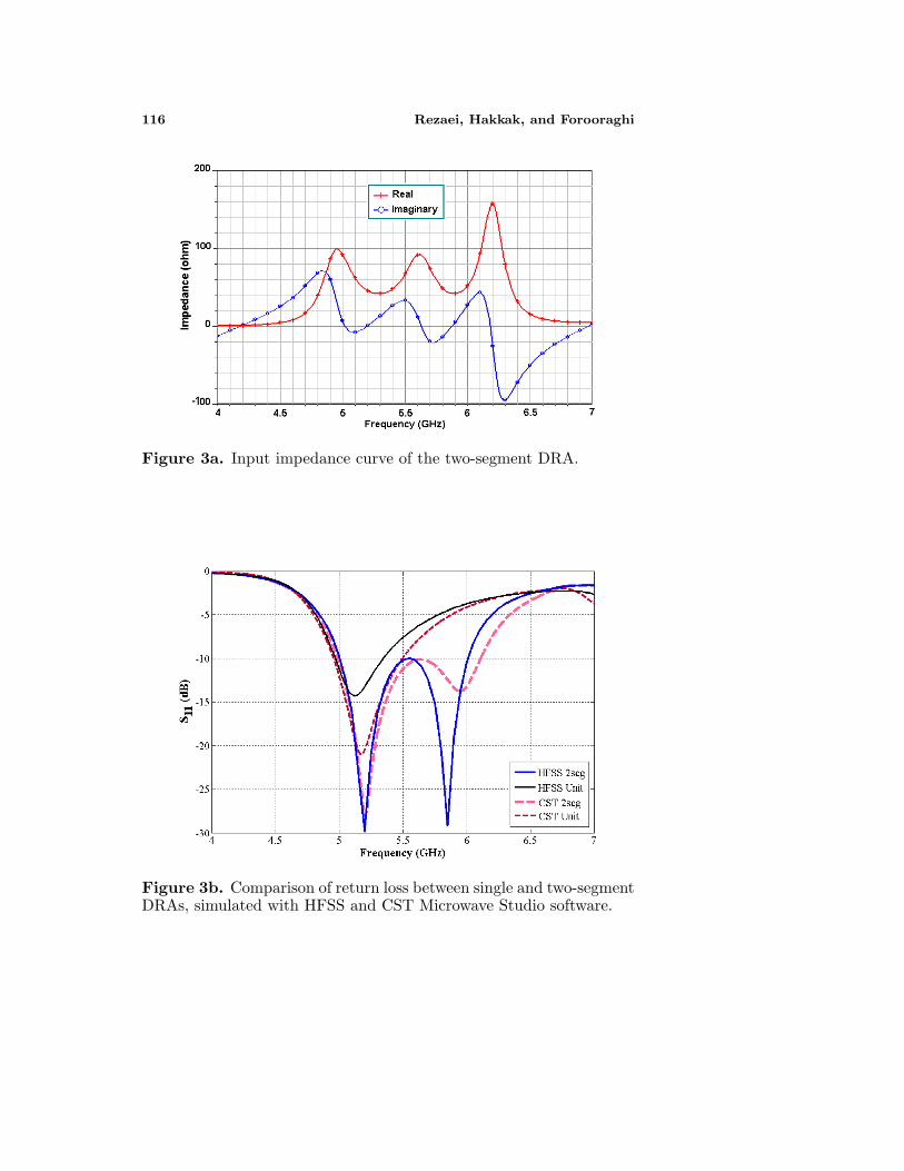
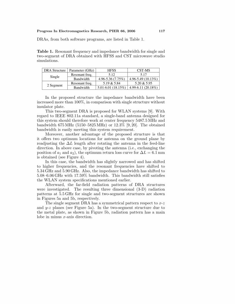
The associated input impedance and return loss curves ofthe designed two-segment DRA are shown in Figures 3a and 3brespectively.
The simulated results (HFSS software) have shown two resonantfrequencies at 5.2 GHz and 5.84 GHz and impedance bandwidthat 5.01–6.01 GHz, which illustrates more than 18.1% frequencybandwidth.
The returns loss curves for two configurations, single and two-segment structures, with the same dimensions are compared inFigure 3b. Also, the results of the HFSS simulations are grosslyconfirmed by using simulation results from CST Microwave Studiowith the same setup as mentioned above. The obtained results areillustrated in Figure 3b, as well.
The comparative simulation results for one- and two-segment
116 Rezaei, Hakkak, and Forooraghi
Figure 3a. Input impedance curve of the two-segment DRA.
Figure 3b. Comparison of return loss between single and two-segmentDRAs, simulated with HFSS and CST Microwave Studio software.
Progress In Electromagnetics Research, PIER 66, 2006 117
DRAs, from both software programs, are listed in Table 1.
Table 1. Resonant frequency and impedance bandwidth for single andtwo-segment of DRA obtained with HFSS and CST microwave studiosimulations.
DRA Structure Parameter (GHz) HFSS CST-MS Resonant freq. 5.12 5.17
Single Bandwidth 4.96-5.36 (7.75%) 4.96-5.49 (10.13%)
Resonant freq. 5.19 & 5.84 5.20 & 5.95 2 Segment
Bandwidth 5.01-6.01 (18.15%) 4.99-6.11 (20.18%)
In the proposed structure the impedance bandwidth have beenincreased more than 100%, in comparison with single structure withoutinsulator plate.
This two-segment DRA is proposed for WLAN systems [9]. Withregard to IEEE 802.11a standard, a single-band antenna designed forthis system should therefore work at center frequency 5487.5 MHz andbandwidth 675 MHz (5150–5825 MHz) or 12.3% [9, 20]. The obtainedbandwidth is easily meeting this system requirement.
Moreover, another advantage of the proposed structure is thatit offers two optimum locations for antenna on the ground plane byreadjusting the ∆L length after rotating the antenna in the feed-linedirection. In above case, by pivoting the antenna (i.e., exchanging theposition of a1 and a2), the optimum return loss curve for ∆L = 6.1 mmis obtained (see Figure 4).
In this case, the bandwidth has slightly narrowed and has shiftedto higher frequencies, and the resonant frequencies have shifted to5.34 GHz and 5.90 GHz. Also, the impedance bandwidth has shifted to5.08–6.06 GHz with 17.59% bandwidth. This bandwidth still satisfiesthe WLAN system specifications mentioned earlier.
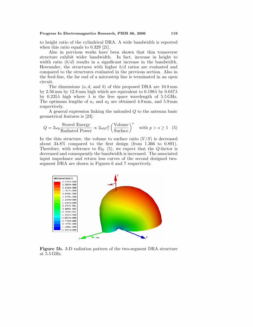
Afterward, the far-field radiation patterns of DRA structureswere investigated. The resulting three dimensional (3-D) radiationpatterns at 5.5 GHz for single and two-segment structures are shownin Figures 5a and 5b, respectively.
The single segment DRA has a symmetrical pattern respect to x-zand y-z planes (see Figure 5a). In the two-segment structure due tothe metal plate, as shown in Figure 5b, radiation pattern has a mainlobe in minus x-axis direction.

118 Rezaei, Hakkak, and Forooraghi
Figure 4. Return loss of the pivoted two-segment DRA.
4. DESIGN OF WIDEBAND DRA
In this section, to obtain better results, the antenna dimensions havebeen enhanced. Greater improvements in bandwidth can be achievedby suitable selection of aspect ratio. For this reason, a scheme like whatwas used for the cylindrical DRA is applied. In cylindrical structure,the resonant frequency of the modes can be adjusted by the radius
Figure 5a. 3-D radiation pattern of single DRA structure at 5.5 GHz.
Progress In Electromagnetics Research, PIER 66, 2006 119
to height ratio of the cylindrical DRA. A wide bandwidth is reportedwhen this ratio equals to 0.329 [21].
Also in pervious works have been shown that thin transversestructure exhibit wider bandwidth. In fact, increase in height towidth ratio (b/d) results in a significant increase in the bandwidth.Hereunder, the structures with higher b/d ratios are evaluated andcompared to the structures evaluated in the previous section. Also inthe feed-line, the far end of a microstrip line is terminated in an opencircuit.
The dimensions (a, d, and b) of this proposed DRA are 10.8 mmby 2.56 mm by 12.8 mm high which are equivalent to 0.198λ by 0.047λby 0.235λ high where λ is the free space wavelength of 5.5 GHz.The optimum lengths of a1 and a2 are obtained 4.9 mm, and 5.9 mmrespectively.
A general expression linking the unloaded Q to the antenna basicgeometrical features is [23]:
Q = 2ω0Stored EnergyRadiated Power
∝ 2ω0εpr
(VolumeSurface
)s
with p > s ≥ 1 (5)
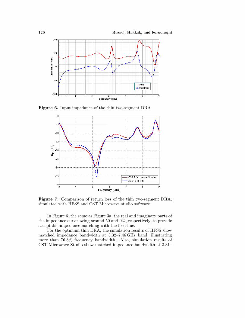
In the thin structure, the volume to surface ratio (V/S) is decreasedabout 34.8% compared to the first design (from 1.366 to 0.891).Therefore, with reference to Eq. (5), we expect that the Q-factor isdecreased and consequently the bandwidth is increased. The associatedinput impedance and return loss curves of the second designed two-segment DRA are shown in Figures 6 and 7 respectively.
Figure 5b. 3-D radiation pattern of the two-segment DRA structureat 5.5 GHz.
120 Rezaei, Hakkak, and Forooraghi
Figure 6. Input impedance of the thin two-segment DRA.
Figure 7. Comparison of return loss of the thin two-segment DRA,simulated with HFSS and CST Microwave studio software.
In Figure 6, the same as Figure 3a, the real and imaginary parts ofthe impedance curve swing around 50 and 0 Ω, respectively, to provideacceptable impedance matching with the feed-line.
For the optimum thin DRA, the simulation results of HFSS showmatched impedance bandwidth at 3.32–7.46 GHz band, illustratingmore than 76.8% frequency bandwidth. Also, simulation results ofCST Microwave Studio show matched impedance bandwidth at 3.31–
Progress In Electromagnetics Research, PIER 66, 2006 121
Table 2. Dimensions, aspect ratio, and impedance bandwidth for 2proposed scheme of the two-segment DRA obtained with simulations.
Dimensions (mm) Bandwidth % Scheme
a1 a2 d b b/dVolume (mm3)
V/S HFSS CST
First 4.8 5.7 6 9.6 1.6 604.8 1.366 18.15 20.18Second 4.9 5.9 2.56 12.8 5 353.89 0.891 76.81 77.41
7.49 GHz band, i.e., more than 77.4% frequency bandwidth. Goodagreement between the two software simulations is obtained for theentire bandwidth. In Table 2, dimensions, volume, aspect ratio, andbandwidth results from HFSS and CST Microwave Studio simulationsfor both of the designed antennas are provided.
The second scheme, the thin structure, occupies 41.5% less volumecompared to the first DRA.
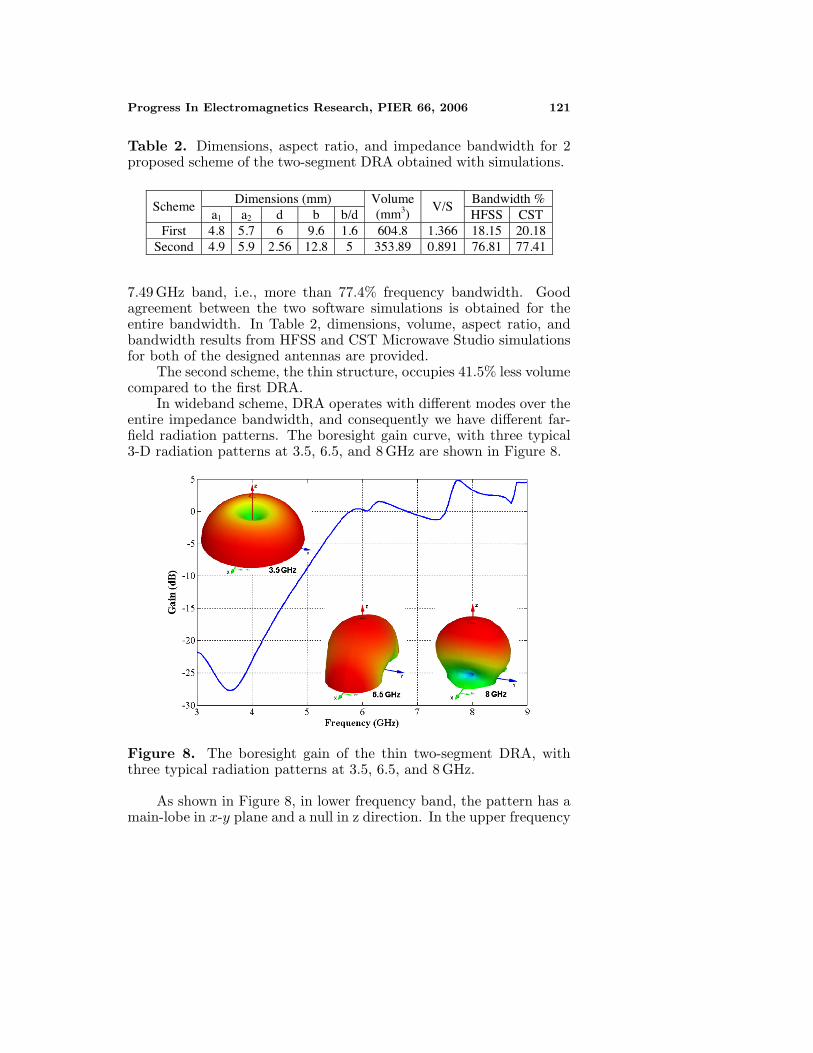
In wideband scheme, DRA operates with different modes over theentire impedance bandwidth, and consequently we have different far-field radiation patterns. The boresight gain curve, with three typical3-D radiation patterns at 3.5, 6.5, and 8 GHz are shown in Figure 8.
Figure 8. The boresight gain of the thin two-segment DRA, withthree typical radiation patterns at 3.5, 6.5, and 8 GHz.
As shown in Figure 8, in lower frequency band, the pattern has amain-lobe in x-y plane and a null in z direction. In the upper frequency
122 Rezaei, Hakkak, and Forooraghi
band, the pattern is semi-hemispherical with a main-lobe in z direction.Moreover, Figure 8 shows 3-dB gain bandwidth in 5.5–7.5 GHz band,i.e., 30.76% frequency bandwidth.
From a number of simulations we have found that CST microwavestudio simulations generally predict wider frequency bandwidth thanHFSS simulations with the same structure. Also, in our simulationswe have found that with a constant volume, the special b/d ratios ofaround 5 provide the widest frequency bandwidth.
5. CONCLUSIONS
In this work, a two-segment rectangular DRA structure separatedby a metal plate was introduced, and performance of this structurewas analyzed. In comparison to a single DRA, this structure offers asignificant reduction of 41.5% in volume. Therefore, such a structureis a potential candidate for use in compact and wideband applications.In the suggested thin DRA with a suitable aspect ratio, an impedancebandwidth of 3.32–7.46 GHz is obtained, which is equivalent to afrequency bandwidth of as high as 76.8% (for S11>10 dB).
ACKNOWLEDGMENT
This work was supported by the Iran Telecommunication ResearchCenter. The authors also express their appreciation to Mr. A. Pirhadiand Mr. F. Hakkak, for valuable advices.
REFERENCES
1. Petosa, A., A. Ittipiboon, Y. M. M. Antar, and D. Roscoe,“Recent advances in dielectric resonator antenna technology,”IEEE Antennas and Propagation Magazine, Vol. 40, No. 3, 35–48, June 1998.
2. Mongia, R. K. and P. Bhartia, “Dielectric resonator antennas— A review and general design relations for resonant frequencyand bandwidth,” International Journal of Microwave Millimeter-Wave Engineering, Vol. 4, 230–247, July 1994.
3. Long, S. A., M. W. McAllister, and L. C. Shen, “The resonantcylindrical dielectric cavity antenna,” IEEE Trans. on Antennasand Propagation, Vol. 31, No. 3, 406–412, May 1983.
4. Luk, K. M. and K. W. Leung, Dielectric Resonator Antennas,Research Studies Press LTD., London, 2003.

Progress In Electromagnetics Research, PIER 66, 2006 123
5. Rao, Q., T. A. Denidni, A. R. Sebak, and R. H. Johnston, “Onimproving impedance matching of a CPW fed low permittivitydielectric resonator antenna,” Progress In ElectromagneticsResearch, PIER 53, 21–29, 2005.
6. Kumar, A. V. P., V. Hamsakutty, J. Yohannan, andK. T. Mathew, “Microstripline fed cylindrical dielectric resonatorantenna with a coplanar parasitic strip,” Progress In Electromag-netics Research, PIER 60, 143–152, 2006.
7. Qian, Z. H., K. W. Leung, and R. S. Chen, “Analysis of circularlypolarized dielectric resonator antenna excited by a spiral slot,”Progress In Electromagnetics Research, PIER 47, 111–121, 2004.
8. Mongia, R. K. and A. Ittipiboon, “Theoretical and experimentalinvestigations on rectangular dielectric resonator antennas,” IEEETran. on Antennas and Propagation, Vol. 45, No. 9, 1348–1356,September 1997.
9. Rezaei, P., M. Hakkak, and K. Forooraghi, “Dielectric resonatorantenna for wireless LAN applications,” IEEE Antennas andPropagation Society International Symposium, Vol. 2, 1005–1008,July 2006.
10. Petosa, A., N. Simons, R. Siushansian, A. Ittipiboon, andM. Cuhaci, “Design and analysis of multisegment dielectricresonator antennas,” IEEE Trans. on Antennas and propagation,Vol. 48, No. 5, 738–742, May 2000.
11. Rashidian, A., K. Forooraghi, and M. Tayfeh-Aligodarz,“Investigations on two-segment dielectric resonator antennas,”Microwave and Optical Technology Letters, Vol. 45, No. 6, 533–537, June 2005.
12. Tam, M. T. K. and R. D. Murch, “Half volume dielectric resonatorantenna designs,” Electronics Letters, Vol. 33, No. 23, 1914–1916,November 1997.
13. Saed, M. and R. Yadla, “Microstrip-fed low profile and compactdielectric resonator antennas,” Progress In ElectromagneticsResearch, PIER 56, 151–162, 2006.
14. Juntunenl, J., O. Kiveka, J. Ollikainen, and P. Vainikainen,“FDTD simulation of a wide-band half volume DRA,” 5thInternational Symposium on Antennas, Propagation and EMTheory, 223–226, August 2000.
15. O’Keefe, S. G., S. P. Kingsley, and S. Saario, “FDTD simulationof radiation characteristics of half-volume HEM and TE-modedielectric resonator antennas,” IEEE Trans. on Antennas andPropagations, Vol. 50, No. 2, 175–179, February 2002.

124 Rezaei, Hakkak, and Forooraghi
16. Kishk, A. A. and A. W. Glisson, “Bandwidth enhancementfor split cylindrical dielectric resonator antennas,” Progress InElectromagnetics Research, PIER 33, 97–118, 2001.
17. Tam, M. T. K. and R. D. Murch, “Compact circular sector andannular sector dielectric resonator antennas,” IEEE Trans. onAntennas and Propagations, Vol. 47, No. 5, 837–842, May 1999.
18. HFSS: High frequency structure simulator based on the finiteelement method, v. 9.2.1, Ansoft Corporation, 2004.
19. CST GmbH 2003 CST MICROWAVE STUDIO(r) User ManualV. 5.0, Darmstadt, Germany (www.cst.de).
20. Lan, K., S. K. Chaudhuri, and S. Safavi-Naeini, “A compactwide-dual-band antenna for bluetooth and wireless LAN appli-cations,” IEEE Antennas and Propagation Society InternationalSymposium, Vol. 2, 926–929, June 2003.
21. Chair, R., A. A. Kishk, and K. F. Lee, “Wideband simplecylindrical dielectric resonator antennas,” IEEE Microwave andWireless Components Letters, Vol. 15, No. 4, 241–243, April 2005.
22. Cooper, M., “Investigation of current and novel rectangulardielectric resonator antennas for broadband applications at l-bandfrequencies,” Master of Engineering Thesis, Carleton University,Ottawa, Canada, 1997.
23. Bit-Babik, G., C. Di-Nallo, and A. Faraone, “Multimode dielectricresonator antenna of very high permittivity,” IEEE Antennas andPropagation Society International Symposium, Vol. 2, 1383–1386,June 2004.


![ANTENNA BEHAVIOUR UNDER DIFFERENT SOIL CONDITIONS...[21] Varun Shukla, Arti Saxena and Swati Jain, A New Rectangular Dielectric Resonator Antenna Compatible for Mobile Communication](https://img.pdfslide.us/doc/110x75/5f935e7cb3469a48e978d7c8/antenna-behaviour-under-different-soil-21-varun-shukla-arti-saxena-and-swati.jpg)