Embed Size (px)
Citation preview
University of Wisconsin MilwaukeeUWM Digital Commons
Theses and Dissertations
August 2017
Design and Development of a Robot GuidedRehabilitation Scheme for Upper ExtremityRehabilitationMd Assad-Uz-ZamanUniversity of Wisconsin-Milwaukee
Follow this and additional works at: https://dc.uwm.edu/etdPart of the Mechanical Engineering Commons
This Thesis is brought to you for free and open access by UWM Digital Commons. It has been accepted for inclusion in Theses and Dissertations by anauthorized administrator of UWM Digital Commons. For more information, please contact [email protected].
Recommended CitationAssad-Uz-Zaman, Md, "Design and Development of a Robot Guided Rehabilitation Scheme for Upper Extremity Rehabilitation"(2017). Theses and Dissertations. 1578.https://dc.uwm.edu/etd/1578
DESIGN AND DEVELOPMENT OF A ROBOT GUIDED REHABILITATION
SCHEME FOR UPPER EXTREMITY REHABILITATION
by
Md Assad-Uz-Zaman
A Thesis Submitted in
Partial Fulfillment of the
Requirements for the Degree of
Master of Science
in Engineering
at
University of Wisconsin-Milwaukee
August 2017
ii
ABSTRACT
DESIGN AND DEVELOPMENT OF A ROBOT GUIDED REHABILITATION
SCHEME FOR UPPER EXTREMITY REHABILITATION
by
Md Assad-Uz-Zaman
University of Wisconsin-Milwaukee, 2017
Under the Supervision of Professor Mohammad Habibur Rahman
To rehabilitate individuals with impaired upper-limb function, we have designed
and developed a robot guided rehabilitation scheme. A humanoid robot, NAO was used
for this purpose. NAO has 25 degrees of freedom. With its sensors and actuators, it can
walk forward and backward, can sit down and stand up, can wave his hand, can speak to
the audience, can feel the touch sensation, and can recognize the person he is meeting.
All these qualities have made NAO a perfect coach to guide the subjects to perform
rehabilitation exercises. To demonstrate rehabilitation exercises with NAO, a library of
recommended rehabilitation exercises involving shoulder (i.e., abduction/adduction,
vertical flexion/extension, and internal/external rotation), and elbow (i.e.,
flexion/extension) joint movements was formed in Choregraphe (graphical programming
interface). In experiments, NAO was maneuvered to instruct and demonstrate the
exercises from the NRL. A complex ‘touch and play’ game was also developed where
NAO plays with the subject that represents a multi-joint movement’s exercise. To
develop the proposed tele-rehabilitation scheme, kinematic model of human upper-
extremity was developed based modified Denavit-Hartenberg notations. A complete
iii
geometric solution was developed to find a unique inverse kinematic solution of human
upper-extremity from the Kinect data. In tele-rehabilitation scheme, a therapist can
remotely tele-operate the NAO in real-time to instruct and demonstrate subjects different
arm movement exercises. Kinect sensor was used in this scheme to get tele-operator’s
kinematics data. Experiments results reveals that NAO can be tele-operated successfully
to instruct and demonstrate subjects to perform different arm movement exercises. A
control algorithm was developed in MATLAB for the proposed robot guided supervised
rehabilitation scheme. Experimental results show that the NAO and Kinect sensor can
effectively be used to supervise and guide the subjects in performing active rehabilitation
exercises for shoulder and elbow joint movements.
Key words: Arm impairment, Robot guided rehabilitation therapy, NAO, Choregraphe,
Kinect, Rehabilitation, Tele-operation, Supervised rehabilitation scheme, Intelligent
control, Kinematics
iv
TABLE OF CONTENTS
ABSTRACT ..............................................................................................................................ii
LIST OF FIGURES ................................................................................................................. vi
LIST OF TABLES ................................................................................................................... ix
ACKNOWLEDGEMENTS ..................................................................................................... x
CHAPTER 1 ............................................................................................................................. 1
1.1 Research Objectives ....................................................................................................... 3
CHAPTER 2 ............................................................................................................................. 5
2.1 Technical Overview: ...................................................................................................... 5
2.1.1 NAO’s Structural Details: ............................................................................... 6
2.1.2 NAO’s Motherboard: .................................................................................... 11
2.1.3 NAO’s Sensors, Vision and Audio System ................................................... 11
2.2 NAO’s Operating System ............................................................................................ 14
2.3 NAO Programming: ..................................................................................................... 16
CHAPTER 3 ........................................................................................................................... 18
3.1 Technical details ........................................................................................................... 18
3.2 Data extraction from Kinect......................................................................................... 20
3.3 Joint parameter from Kinect data ................................................................................ 22
3.3.1 Coordinate frame assignment ........................................................................ 22
3.3.2 D-H parameters ............................................................................................. 24
3.3.3 Inverse Kinematics ........................................................................................ 28
CHAPTER 4 ........................................................................................................................... 35
4.1 Choregraphe ................................................................................................................. 35
v
4.2 NAO’s Rehabilitation Library (NRL) ......................................................................... 40
4.2.1 Single joint movements ................................................................................. 40
4.2.2 Multi joint movements .................................................................................. 46
4.2.3 Cooperative exercise ..................................................................................... 50
CHAPTER 5 ........................................................................................................................... 54
5.1 Methodology ................................................................................................................ 54
5.2 Performance analysis ................................................................................................... 56
CHAPTER 6 ........................................................................................................................... 71
6.1 Supervision system using NAO and Kinect ................................................................ 71
6.2 Performance analysis ................................................................................................... 72
CHAPTER 7 ........................................................................................................................... 78
8.1 Conclusion .................................................................................................................... 78
8.2 Future Works ................................................................................................................ 79
References: .............................................................................................................................. 80
vi
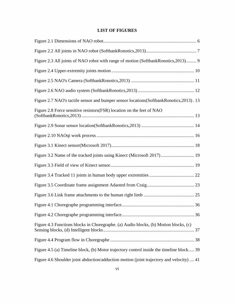
LIST OF FIGURES
Figure 2.1 Dimensions of NAO robot................................................................................. 6
Figure 2.2 All joints in NAO robot (SoftbankRonotics,2013)............................................ 7
Figure 2.3 All joints of NAO robot with range of motion (SoftbankRonotics,2013) ......... 9
Figure 2.4 Upper-extremity joints motion ........................................................................ 10
Figure 2.5 NAO's Camera (SoftbankRonotics,2013) ....................................................... 11
Figure 2.6 NAO audio system (SoftbankRonotics,2013) ................................................. 12
Figure 2.7 NAO's tactile sensor and bumper sensor locations(SoftbankRonotics,2013) . 13
Figure 2.8 Force sensitive resistors(FSR) location on the feet of NAO
(SoftbankRonotics,2013) .................................................................................................. 13
Figure 2.9 Sonar sensor location(SoftbankRonotics,2013) .............................................. 14
Figure 2.10 NAOqi work process ..................................................................................... 16
Figure 3.1 Kinect sensor(Microsoft 2017) ........................................................................ 18
Figure 3.2 Name of the tracked joints using Kinect (Microsoft 2017) ............................. 19
Figure 3.3 Field of view of Kinect sensor ......................................................................... 19
Figure 3.4 Tracked 11 joints in human body upper extremities ....................................... 22
Figure 3.5 Coordinate frame assignment Adaoted from Craig ......................................... 23
Figure 3.6 Link frame attachments to the human right limb ............................................ 25
Figure 4.1 Choregraphe programming interface ............................................................... 36
Figure 4.2 Choregraphe programming interface ............................................................... 36
Figure 4.3 Functions blocks in Choregraphe. (a) Audio blocks, (b) Motion blocks, (c)
Sensing blocks, (d) Intelligent blocks ............................................................................... 37
Figure 4.4 Program flow in Choregraphe ......................................................................... 38
Figure 4.5 (a) Timeline block, (b) Motor trajectory control inside the timeline block..... 39
Figure 4.6 Shoulder joint abduction/adduction motion (joint trajectory and velocity) .... 41
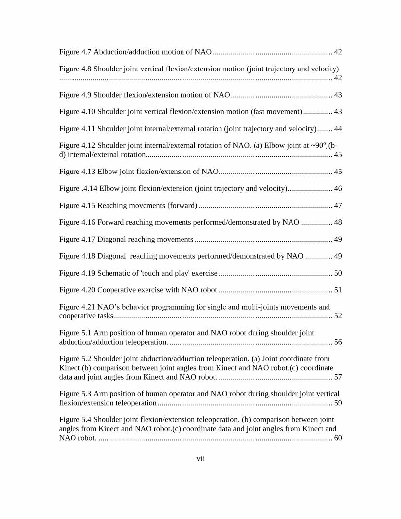
vii
Figure 4.7 Abduction/adduction motion of NAO ............................................................. 42
Figure 4.8 Shoulder joint vertical flexion/extension motion (joint trajectory and velocity)
........................................................................................................................................... 42
Figure 4.9 Shoulder flexion/extension motion of NAO.................................................... 43
Figure 4.10 Shoulder joint vertical flexion/extension motion (fast movement) ............... 43
Figure 4.11 Shoulder joint internal/external rotation (joint trajectory and velocity) ........ 44
Figure 4.12 Shoulder joint internal/external rotation of NAO. (a) Elbow joint at ~90o, (b-
d) internal/external rotation............................................................................................... 45
Figure 4.13 Elbow joint flexion/extension of NAO.......................................................... 45
Figure .4.14 Elbow joint flexion/extension (joint trajectory and velocity)....................... 46
Figure 4.15 Reaching movements (forward) .................................................................... 47
Figure 4.16 Forward reaching movements performed/demonstrated by NAO ................ 48
Figure 4.17 Diagonal reaching movements ...................................................................... 49
Figure 4.18 Diagonal reaching movements performed/demonstrated by NAO .............. 49
Figure 4.19 Schematic of 'touch and play' exercise .......................................................... 50
Figure 4.20 Cooperative exercise with NAO robot .......................................................... 51
Figure 4.21 NAO’s behavior programming for single and multi-joints movements and
cooperative tasks ............................................................................................................... 52
Figure 5.1 Arm position of human operator and NAO robot during shoulder joint
abduction/adduction teleoperation. ................................................................................... 56
Figure 5.2 Shoulder joint abduction/adduction teleoperation. (a) Joint coordinate from
Kinect (b) comparison between joint angles from Kinect and NAO robot.(c) coordinate
data and joint angles from Kinect and NAO robot. .......................................................... 57
Figure 5.3 Arm position of human operator and NAO robot during shoulder joint vertical
flexion/extension teleoperation ......................................................................................... 59
Figure 5.4 Shoulder joint flexion/extension teleoperation. (b) comparison between joint
angles from Kinect and NAO robot.(c) coordinate data and joint angles from Kinect and
NAO robot. ....................................................................................................................... 60
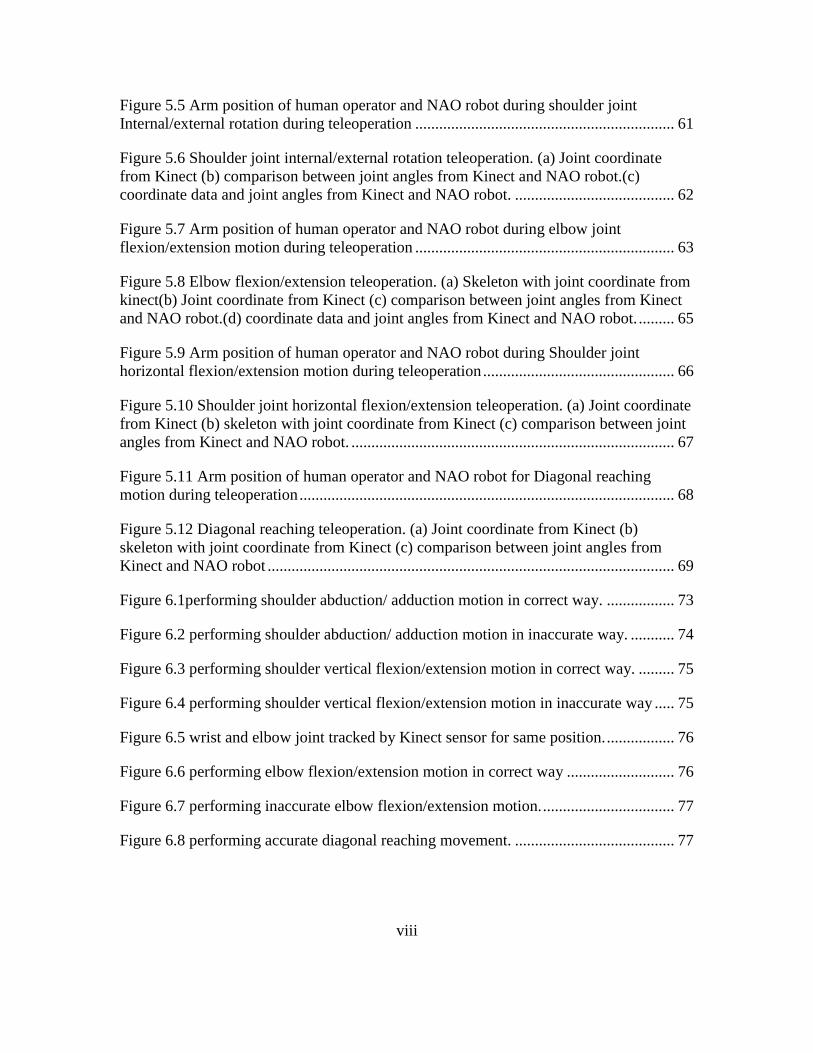
viii
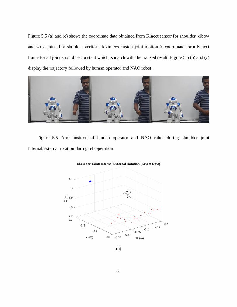
Figure 5.5 Arm position of human operator and NAO robot during shoulder joint
Internal/external rotation during teleoperation ................................................................. 61
Figure 5.6 Shoulder joint internal/external rotation teleoperation. (a) Joint coordinate
from Kinect (b) comparison between joint angles from Kinect and NAO robot.(c)
coordinate data and joint angles from Kinect and NAO robot. ........................................ 62
Figure 5.7 Arm position of human operator and NAO robot during elbow joint
flexion/extension motion during teleoperation ................................................................. 63
Figure 5.8 Elbow flexion/extension teleoperation. (a) Skeleton with joint coordinate from
kinect(b) Joint coordinate from Kinect (c) comparison between joint angles from Kinect
and NAO robot.(d) coordinate data and joint angles from Kinect and NAO robot. ......... 65
Figure 5.9 Arm position of human operator and NAO robot during Shoulder joint
horizontal flexion/extension motion during teleoperation ................................................ 66
Figure 5.10 Shoulder joint horizontal flexion/extension teleoperation. (a) Joint coordinate
from Kinect (b) skeleton with joint coordinate from Kinect (c) comparison between joint
angles from Kinect and NAO robot. ................................................................................. 67
Figure 5.11 Arm position of human operator and NAO robot for Diagonal reaching
motion during teleoperation .............................................................................................. 68
Figure 5.12 Diagonal reaching teleoperation. (a) Joint coordinate from Kinect (b)
skeleton with joint coordinate from Kinect (c) comparison between joint angles from
Kinect and NAO robot ...................................................................................................... 69
Figure 6.1performing shoulder abduction/ adduction motion in correct way. ................. 73
Figure 6.2 performing shoulder abduction/ adduction motion in inaccurate way. ........... 74
Figure 6.3 performing shoulder vertical flexion/extension motion in correct way. ......... 75
Figure 6.4 performing shoulder vertical flexion/extension motion in inaccurate way ..... 75
Figure 6.5 wrist and elbow joint tracked by Kinect sensor for same position. ................. 76
Figure 6.6 performing elbow flexion/extension motion in correct way ........................... 76
Figure 6.7 performing inaccurate elbow flexion/extension motion. ................................. 77
Figure 6.8 performing accurate diagonal reaching movement. ........................................ 77
ix
LIST OF TABLES
Table 2.1 Joint motion range of NAO and human arm……………………………10
Table 3.1 Modified Denavit-Hartenberg parameters……………………………....25
Table 4.1 NAO’s rehabilitation exercise…………………………………………..53
x
ACKNOWLEDGEMENTS
First and foremost, I would like to pay my gratitude to almighty ALLAH (SWT), who
gives me the strength, courage and patience for completing this thesis work at last. I would
like to acknowledge my advisor Dr. Mohammad Habibur Rahman for his immense support
and guidance. Dr. Rahman recognized my potential to contribute to the rehabilitation
robotics field. He has also served as a constant source of encouragement and counseling
during the journey towards my MS. My committee members have been truly wonderful in
their comments and creative ideas. I thank Dr. Yongjin Sung and Dr. Veysi Malkoc for
serving on my thesis committee. I would also like to thank my lab mate Md Rasedul Islam,
PhD Student at mechanical engineering department, who has been a ceaseless source of
inspiration and motivation during this journey. A special thanks to my other lab-mates
Rezwan, Mark, Chris, Liu, Fidel, Nick and Anna, for helping me and providing a
supportive environment to work in.
I would like to thank Professor Dr. Mohammad Mashud for his support,
encouragement and enlightenment throughout my life.
I want to convey my deepest gratitude to my father and mother for their endless
struggle to bring me at this level and their encouragement. I also want to mention my
gratitude to my father-in-law and mother-in-law for their believe and support for me.
Finally yet importantly, I like to mention my heartiest thanks to an integral part of
my life, my wife Zannatul Ferdous Monika, for her enormous patience, continuous
support and encouragement during this stressful time.

1
CHAPTER 1
INTRODUCTION
Upper extremity impairment is very common due to geriatric disorders and/or following a
stroke or other conditions such as TBI, SCI, sports, falls, and traumatic injuries. According to the
World Health Organization (WHO), a stroke is a sudden ischemic or hemorrhagic interruption in
the blood flow supplying oxygen and nutrients to the brain tissue. This event results in brain cell
death and consequently in partial loss of neurological function (World Health Organization 2010).
The occurrence of strokes has been progressively increasing. Currently, according to CDC
(Centers for Disease Control and Prevention), strokes are the fourth leading cause of mortality in
the USA. The consequences of strokes extend further than patient mortality. The majority of stroke
survivors live with long-term disabilities, leading to serious social and economic impacts: it is
estimated that stroke and heart diseases cost more than $34 billion annually worldwide
(Mozaffarian, Benjamin et al. 2015). These numbers will continue to rise as the aging population
increases.
Rehabilitation programs are the main method to promote functional recovery in these
individuals (Gresham, Alexander et al. 1997, Truelsen, Piechowski-Jozwiak et al. 2006). The
Conventional therapeutic approach requires a long commitment by a therapist or clinician.
Unfortunately, there is a consistent shortage of qualified physiotherapists/clinicians both in
developing countries and in the developed countries as well. Beside this, the treatment duration is
usually very long, requiring many hours of the therapist’s time for each individual patient. On top
of these facts, the number of such cases is constantly growing. Therefore, an alternative to the
conventional treatments is essential.
2
To assist physically disabled individuals with impaired upper limb function, extensive
research has been carried out in many branches of robotics, particularly on wearable robots e.g.,
exoskeletons (Rahman, Kiguchi et al. 2006, Garrec, Friconneau et al. 2008, Nef, Guidali et al.
2009). Although much progress has been made, we are still far from the desired achievement, as
existing robots have not yet been able to restore body mobility or function.
Several hypotheses exist as to how upper extremity rehabilitation may be improved. Studies
reveal that intensive and repetitive therapies significantly improve motor skill (Huang et al., 2009).
Note that the passive rehabilitation therapy does not contribute in building muscle but does help
to prevent contractures, increasing the range of motion and thus maintains and promotes mobility
of the patients (Wang, 2011). Therefore, once resistance to passive arm movements in individuals
has diminished it is essential that they practice active movements. For example, the subjects
perform any specific task under the guidance of a physiotherapist or a caregiver. To provide such
therapy with a robotic rehabilitation protocol, the robotic devices will guide the subject’s
movement to complete the specified task. Further studies reveal that enhanced motor learning
occurs in the ‘active rehabilitation therapy’ mode, when patients (independently) practice a variety
of functional tasks (Winstein, Merians et al. 1999) such as grasping and reaching movements and
receive feedback (e.g., visual and haptic feedback) intermittently (Winstein, Miller et al. 2003,
Lum, Burgar et al. 2004). However, no such robot has existed to provide such guided rehabilitation.
To contribute in this area, in this research we have proposed to develop a robot guided
rehabilitation scheme for upper extremity rehabilitation. A humanoid robot, NAO was used for
this purpose. NAO has 25 degrees of freedom. With its sensors and actuators, it can walk forward
and backward, can sit down and stand up, can wave his hand, can speak to the audience, can feel
3
the touch sensation, and can recognize the person he is meeting. All these qualities have made
NAO a perfect coach to guide the subjects to perform rehabilitation exercises.
1.1 Research Objectives
The specific aims of this research project are:
Aim-1: to develop a library of active rehabilitation exercises for NAO robot.
Aim-2: to develop a tele-rehabilitation scheme for NAO robot
Aim-3: to develop NAO guided supervised rehabilitation scheme
Experimental results reveal that NAO can be effectively used to supervise and guide the
subjects in performing active rehabilitation exercises for shoulder and elbow joint movements.
This thesis is organized as follows:
Chapter 2: Humanoid Robot, NAO
This chapter outlines the overall design and specifications of NAO. It gives the reader an overall
sense of the complete hardware package and the components that comprise it.
Chapter 3: Motion Capture System Kinect and Kinematics
Chapter 3 describes Kinect sensor and human upper-extremity kinematics. The modified DH
notations were used to develop the kinematic modeling.
Chapter 4: NAO’s Rehabilitation Library (NRL)
4
This chapter describes NAO’s graphical programming interface (Choregraphe). A library of
rehabilitation exercises for NAO (NRL) was developed in Choregraphe environment.
Chapter 5: Tele-rehabilitation scheme
This chapter presents a tele-rehabilitation scheme. It is expected a therapist can remotely tele-
operate the NAO in real-time to instruct and demonstrate the subjects different arm movement
exercises. Kinect sensor was used in this scheme to get tele-operator’s kinematics data.
Chapter 6: NAO guided supervised rehabilitation
This chapter presents experimental results of NAO guided supervised rehabilitation.
Chapter 7: Conclusions and Recommendations
Finally, the Conclusions section of the paper summarizes the research outcomes and suggests
directions for further research in section Recommendations.
5
CHAPTER 2
HUMANOID ROBOT NAO
Humanoid robot NAO, developed by Aldebaran Robotics, is one of the most promising
autonomous programmable robot (Robotics). According to the SoftBank Robotics, currently
almost 9000 NAO’s are in use throughout the world and showing success in the fields of research
and education (Robotics). At the year, 2004 Aldebaran first reveals NAO, which was developed
under ‘Project NAO’. NAO has drawn the attention of all the people due to its capability of human
like acrobatic movement and human like communication capability such as vision, speech, hearing
and touch sensing capability. All these functionalities in NAO’s were make possible due to its
facilities with 25 joints’ motions along with two cameras, four microphones, two loud speakers,
nine tactile sensors, and eight pressure sensors (Robotics).With its 25 degree of freedoms it can
mimic almost all-simple human motion. NAO can do all simple human motions such as walking
forward and backward, sitting down and standing up, waving hand, playing soccer etc. However,
its technical background is not as simple as it looks like. NAO has different types of sensors,
actuators, onboard processors etc. Different version of NAO robots is available now. In this
research we have used NAO V5. Technical details for this version is described in next section.
2.1 Technical Overview:
Technical details of NAO robot is provided in Aldebaran
documentation(SoftbankRonotics,2013)
6
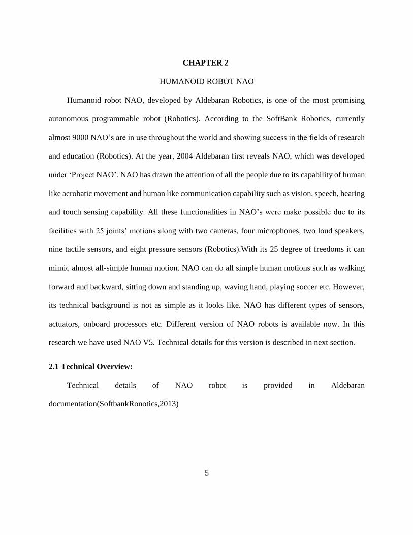
2.1.1 NAO’s Structural Details:
NAO V5 is 574 mm tall and 275 mm width with 5.4 kg body weight. Its upper arm length is
105 mm and lower arm length is 55.95 mm. Its thigh length 100 mm, tibial length 102.90 mm and
foot height 45.19 mm.
Figure 2.1 Dimensions of NAO robot
7
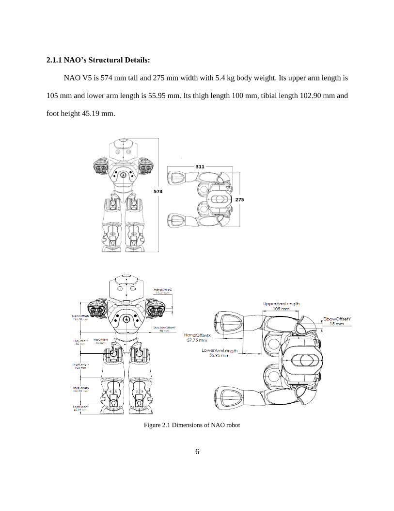
NAO has total 25 joints. Two joints in head, five joints in each arm along with hand close and
open motions, five joints in each leg and two hip joints.
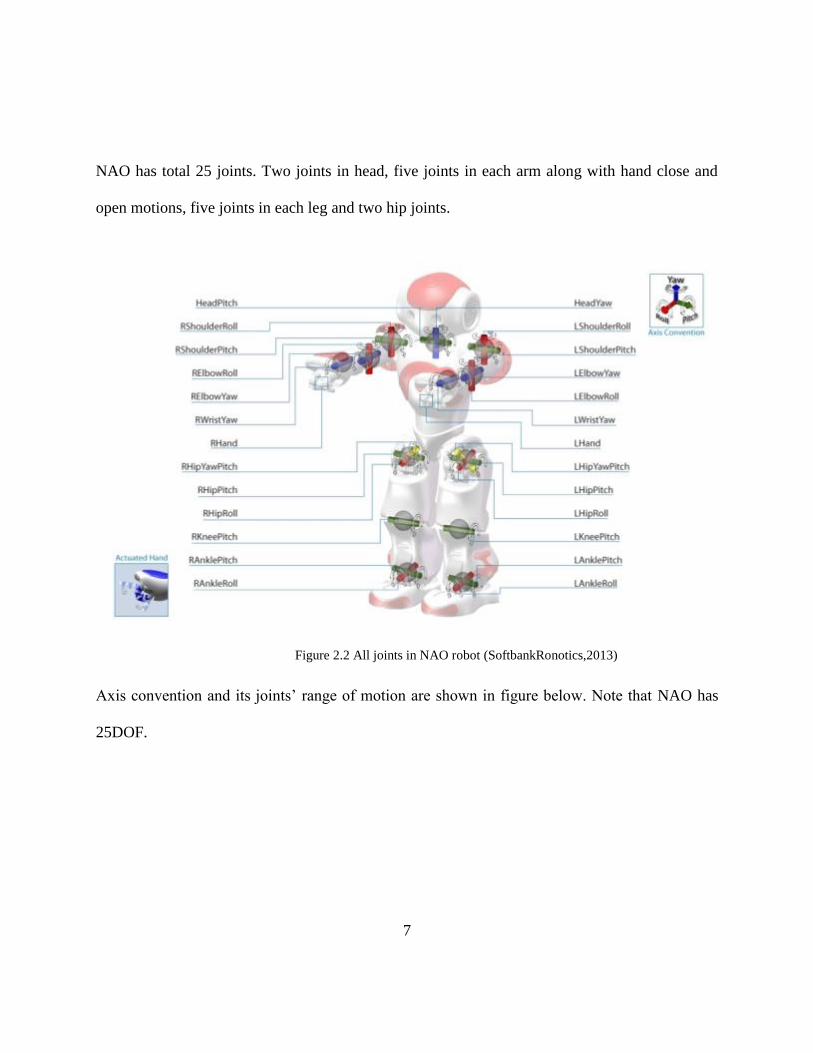
Axis convention and its joints’ range of motion are shown in figure below. Note that NAO has
25DOF.
Figure 2.2 All joints in NAO robot (SoftbankRonotics,2013)
8
(a) Sign convention
(b) Head pitch (Side view) and Head
yaw (Top view)
(c) Hip joint right yaw pitch and left yaw
pitch
(d) left arm joints and range of
motions
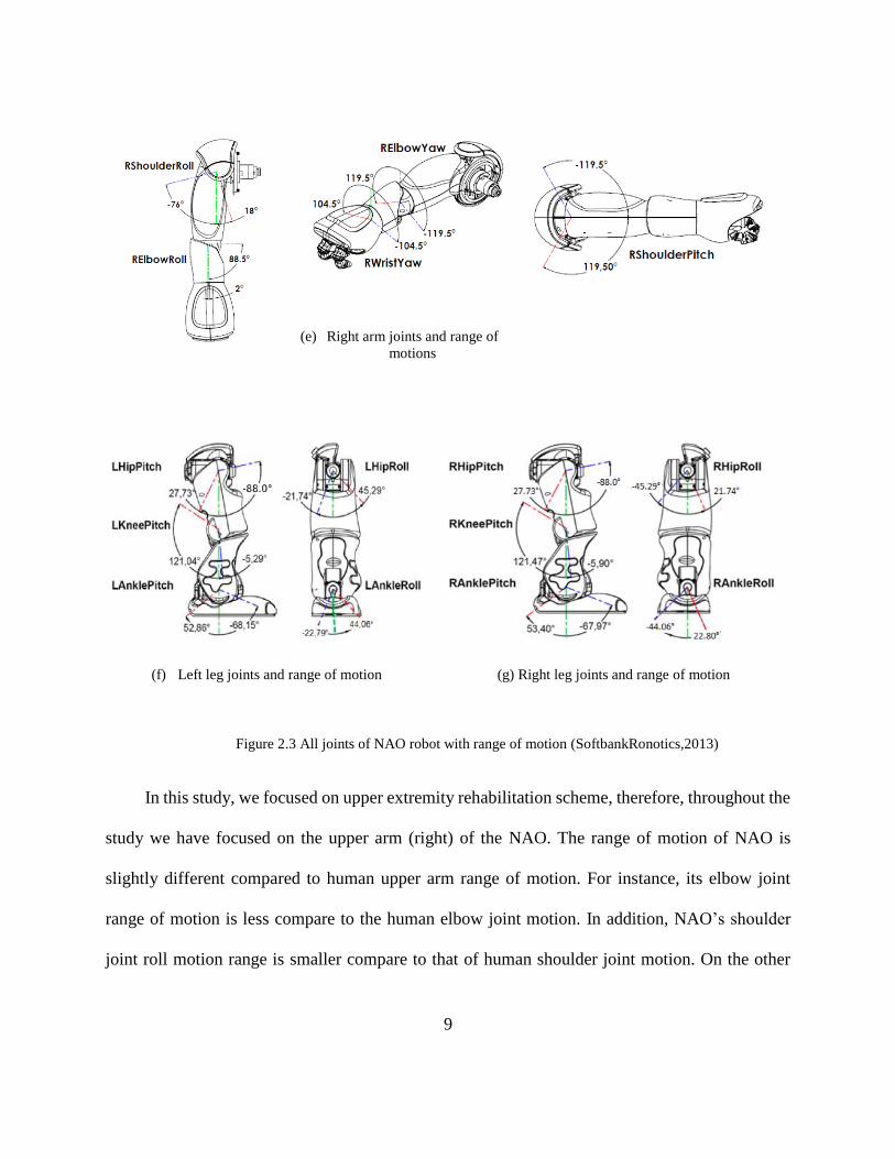
9
(e) Right arm joints and range of
motions
(f) Left leg joints and range of motion
(g) Right leg joints and range of motion
In this study, we focused on upper extremity rehabilitation scheme, therefore, throughout the
study we have focused on the upper arm (right) of the NAO. The range of motion of NAO is
slightly different compared to human upper arm range of motion. For instance, its elbow joint
range of motion is less compare to the human elbow joint motion. In addition, NAO’s shoulder
joint roll motion range is smaller compare to that of human shoulder joint motion. On the other
Figure 2.3 All joints of NAO robot with range of motion (SoftbankRonotics,2013)
10
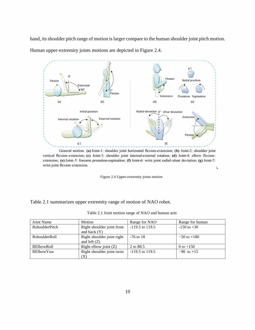
hand, its shoulder pitch range of motion is larger compare to the human shoulder joint pitch motion.
Human upper-extremity joints motions are depicted in Figure 2.4.
Figure 2.4 Upper-extremity joints motion
Table 2.1 summarizes upper extremity range of motion of NAO robot.
Table 2.1 Joint motion range of NAO and human arm
Joint Name Motion Range for NAO Range for human
RshoulderPitch Right shoulder joint front
and back (Y)
-119.5 to 119.5 -150 to +30
RshoulderRoll Right shoulder joint right
and left (Z)
-76 to 18 −50 to +180
RElbowRoll Right elbow joint (Z) 2 to 88.5 0 to +150
RElbowYaw Right shoulder joint twist
(X)
-119.5 to 119.5
−90 to +15
11
2.1.2 NAO’s Motherboard:
NAO has its own central processing unit (CPU) to execute command and control all the
sensors. Its motherboard consists of Intel ATOM 2530 1.6 GHz processor with cache memory
512KB, clock speed 1.6 GHZ and FSB speed 533mHz, 1GB RAM, 2GB flash memory and 8GB
Micro SDHC. In addition, it provides communication through WiFi using IEEE 802.11 a/b/g/n
protocol, Ethernet, and USB interface. Its USB port mainly used for updating the robot operating
system.
2.1.3 NAO’s Sensors, Vision and Audio System
To explore the surroundings, to take a command from the user, and to give feedback
information both to the control unit and to the user, NAO is equipped with different types of
sensors, vision and audio system.
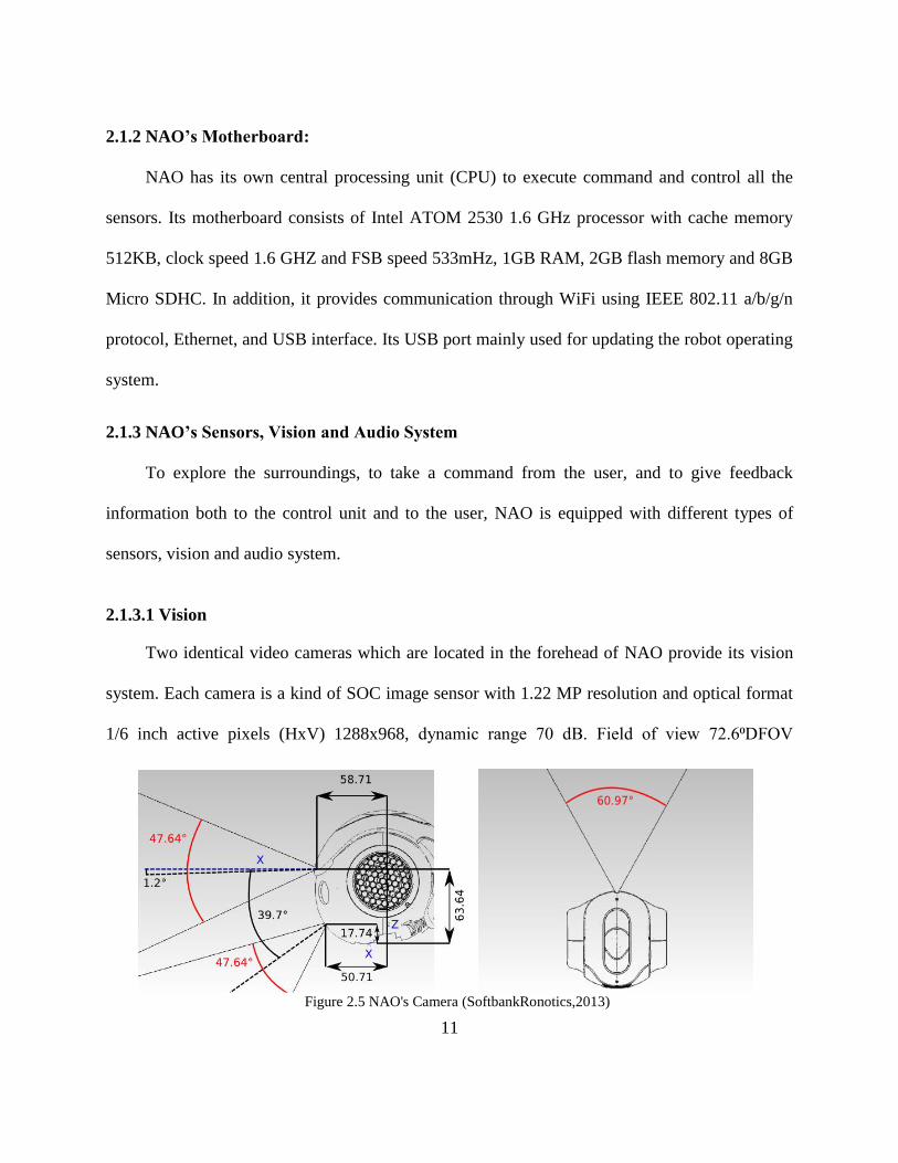
2.1.3.1 Vision
Two identical video cameras which are located in the forehead of NAO provide its vision
system. Each camera is a kind of SOC image sensor with 1.22 MP resolution and optical format
1/6 inch active pixels (HxV) 1288x968, dynamic range 70 dB. Field of view 72.6⁰DFOV
Figure 2.5 NAO's Camera (SoftbankRonotics,2013)
12
(60.9⁰HFOV, 47.6⁰VFOV). Focus range 30cm to infinity. Camera data streaming rate 30fps.
Through this vision system, NAO can detect human face, object, provide live video streaming for
image processing etc.
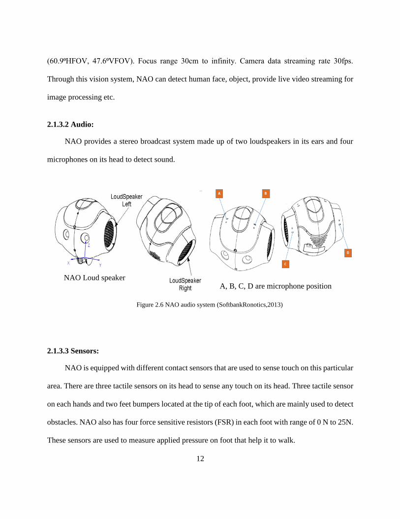
2.1.3.2 Audio:
NAO provides a stereo broadcast system made up of two loudspeakers in its ears and four
microphones on its head to detect sound.
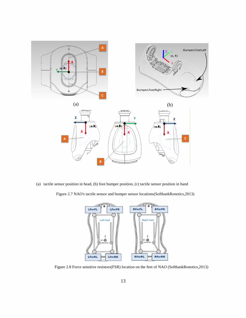
2.1.3.3 Sensors:
NAO is equipped with different contact sensors that are used to sense touch on this particular
area. There are three tactile sensors on its head to sense any touch on its head. Three tactile sensor
on each hands and two feet bumpers located at the tip of each foot, which are mainly used to detect
obstacles. NAO also has four force sensitive resistors (FSR) in each foot with range of 0 N to 25N.
These sensors are used to measure applied pressure on foot that help it to walk.
A, B, C, D are microphone position NAO Loud speaker
Figure 2.6 NAO audio system (SoftbankRonotics,2013)
13
(a) tactile sensor position in head, (b) foot bumper position, (c) tactile sensor position in hand
(a) (b)
Figure 2.7 NAO's tactile sensor and bumper sensor locations(SoftbankRonotics,2013)
Figure 2.8 Force sensitive resistors(FSR) location on the feet of NAO (SoftbankRonotics,2013)
14
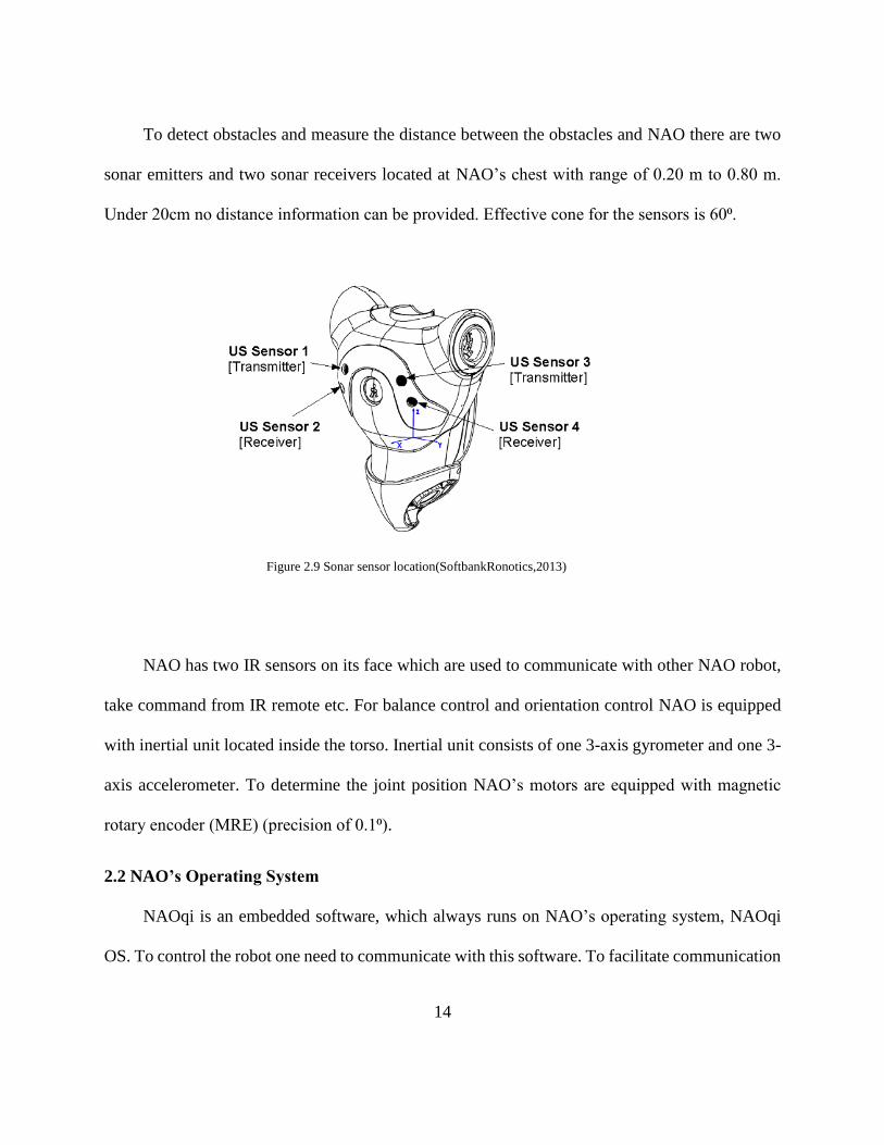
To detect obstacles and measure the distance between the obstacles and NAO there are two
sonar emitters and two sonar receivers located at NAO’s chest with range of 0.20 m to 0.80 m.
Under 20cm no distance information can be provided. Effective cone for the sensors is 60⁰.
NAO has two IR sensors on its face which are used to communicate with other NAO robot,
take command from IR remote etc. For balance control and orientation control NAO is equipped
with inertial unit located inside the torso. Inertial unit consists of one 3-axis gyrometer and one 3-
axis accelerometer. To determine the joint position NAO’s motors are equipped with magnetic
rotary encoder (MRE) (precision of 0.1⁰).
2.2 NAO’s Operating System
NAOqi is an embedded software, which always runs on NAO’s operating system, NAOqi
OS. To control the robot one need to communicate with this software. To facilitate communication
Figure 2.9 Sonar sensor location(SoftbankRonotics,2013)
15
with NAOqi we need to use NAOqi Software Development Kit (SDK). NAOqi SDK is actually a
set of application programming interfaces (API) which vary for different programming platform.
The Softbank robotics provides API for C++, Python and Java to develop application for NAO.
NAOqi OS is the main operating system for NAO robot, which is a GNU/Linux distribution based
on Gentoo. It provides all necessary libraries and programs that are required to operate NAOqi.
NAOqi OS compatible with other operating system such as Windows, Mac, Linux. In the NAOqi
OS the main programming framework that is used to program NAO is NAOqi framework (2013).
Homogeneous communication between different modules (motion, audio, video), homogeneous
programming, and homogeneous information sharing all are possible through this framework. This
framework provides a cross-platform, cross language and introspection support. Introspection
means this framework knows which functions are available in the different modules and where.
Parallelism, resources, event management, synchronization all basic robotics need fulfilled by this
framework.
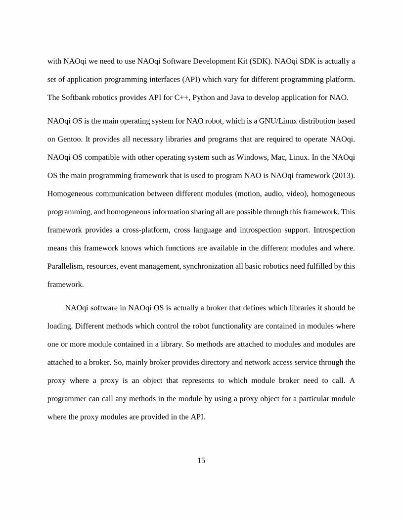
NAOqi software in NAOqi OS is actually a broker that defines which libraries it should be
loading. Different methods which control the robot functionality are contained in modules where
one or more module contained in a library. So methods are attached to modules and modules are
attached to a broker. So, mainly broker provides directory and network access service through the
proxy where a proxy is an object that represents to which module broker need to call. A
programmer can call any methods in the module by using a proxy object for a particular module
where the proxy modules are provided in the API.
16
2.3 NAO Programming:
We can build behavior for NAO by using a high level block based programming environment
called Choregraphe (Sahrmann and Norton 1977) or by using other programming languages for
which appropriate API is available. Choregraphe is a multi-platform desktop application that can
create complex behaviors without writing any code. It is actually a graphical programming
interface. Different functionalities of NAO are represented here as behavior blocks. All those
blocks provide specific task for NAO. By combining different blocks, one can create new behavior
block. Like LabVIEW and Simulink, Choregraphe use same concept of signal flow and executes
the blocks in order they are connected to each other. It provides lots of built in behavior blocks
that can perform specific task. The build behavior in Choregraphe can be tested in a virtual NAO
or it can be implemented as a permanent behavior in physical NAO. In addition, Choregraphe
Figure 2.10 NAOqi work process
17
provides behavior control of NAO. One can remove an old behavior or can add a new behavior
through this. It is very user friendly. Options are available to create new behavior blocks for
advanced functionality (of NAO) in Choregraphe by using programming language python with
python API.
For code programming Aldebaran provides API for language C++, Python and Java for
NAO V5. Python SDK for NAO robot requires Python 2.7-32 bits. It only works for this
environment (Python 2.7-32 bits). C++ SDK requires a C++ compiler for different OS. For
Windows, C++ SDK only works for Visual Studio 2010. Windows also have some limitations,
there is no C++ cross compiler. As a solution to this problem, Windows users need to install
qiBuild, a tool design to generate cross platform projects using CMake along with the C++ SDK.
In our study, we have used Python 2.7.13 and Python SDK to control the NAO for advanced
functionality.
18
CHAPTER 3
KINECT MOTION CAPTURE SYSTEM AND KINEMATICS
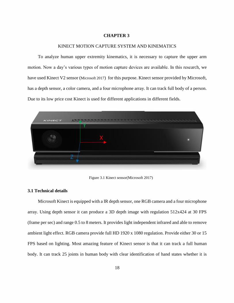
To analyze human upper extremity kinematics, it is necessary to capture the upper arm
motion. Now a day’s various types of motion capture devices are available. In this research, we
have used Kinect V2 sensor (Microsoft 2017) for this purpose. Kinect sensor provided by Microsoft,
has a depth sensor, a color camera, and a four microphone array. It can track full body of a person.
Due to its low price cost Kinect is used for different applications in different fields.
Figure 3.1 Kinect sensor(Microsoft 2017)
3.1 Technical details
Microsoft Kinect is equipped with a IR depth sensor, one RGB camera and a four microphone
array. Using depth sensor it can produce a 3D depth image with regulation 512x424 at 30 FPS
(frame per sec) and range 0.5 to 8 meters. It provides light independent infrared and able to remove
ambient light effect. RGB camera provide full HD 1920 x 1080 regulation. Provide either 30 or 15
FPS based on lighting. Most amazing feature of Kinect sensor is that it can track a full human
body. It can track 25 joints in human body with clear identification of hand states whether it is
19
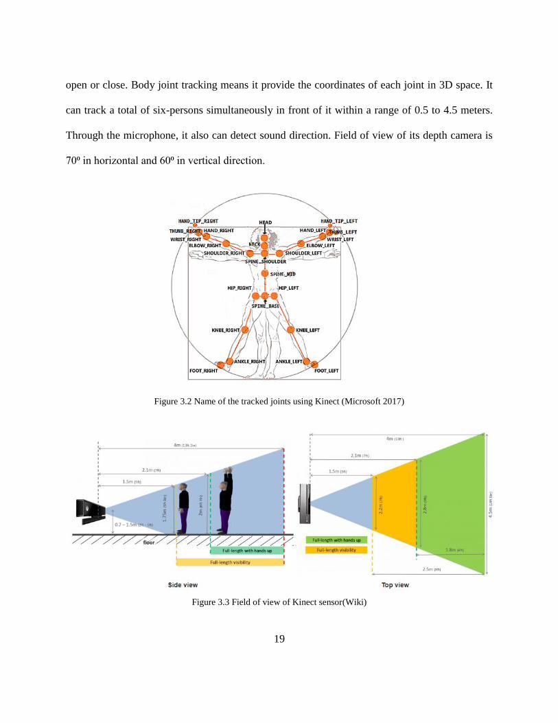
open or close. Body joint tracking means it provide the coordinates of each joint in 3D space. It
can track a total of six-persons simultaneously in front of it within a range of 0.5 to 4.5 meters.
Through the microphone, it also can detect sound direction. Field of view of its depth camera is
70⁰ in horizontal and 60⁰ in vertical direction.
Figure 3.2 Name of the tracked joints using Kinect (Microsoft 2017)
Figure 3.3 Field of view of Kinect sensor(Wiki)
20
Kinect V2 came with the software development kit (SDK) by which one can extract Kinect data
through programming. Kinect V2 SDK is compatible only with the Microsoft Visual Studio 2012
or its higher version. To run this SDK the windows operating system must be windows 8 or higher
with 64-bit processor and minimum 4 GB memory. Data can be streamed only through the USB
3.0 port.
3.2 Data extraction from Kinect
To access the Kinect data we used Kinect V2 SDK. This SDK provides necessary API to
extract Kinect data using Visual studio 2012 or higher. It is (SDK) compatible with programing
language C++, C#, Java.
In this research, we have extracted Kinect data to analyze human arm kinematics and also to tele-
operate the NAO (in real-time) to establish the proposed tele-rehabilitation scheme.
As mentioned in Chapter-3 to control the NAO robot, C++ language can be used with proper SDK.
If C++ is used for both NAO and Kinect then this two systems can be operated in a same platform.
However, the SDK provided for this NAO robot is only compatible with Visual studio 2010, and
Kinect V2 SDK only works with Visual studio 2012 or its higher version. That is why, it is difficult
to control two systems in a common platform. Therefore, for NAO robot we use Python 2.7 32bit.
In addition, data analysis in C++ need too much coding and debugging of C++ code is little bit
difficult. As, C++ is a low level programming language, it may cause serious trouble to the
processor due to bugs in the coding. For all these reasons, we used MATLAB to extract data from
Kinect. Microsoft does not provide any SDK for MATLAB. But there is a toolbox call Kin2
(Terven and Córdova-Esparza 2016) developed in MATLAB to extract data from Kinect. We used
21
this toolbox for our study. This toolbox actually call C++ function from MATLAB by using MAX
function. Main data extraction code is written in C++. To use this toolbox a C++ compiler is
required. In our case, we used Visual studio 2015. However, the performance of the Kin2
application is not as fast as a native C++ application (Terven and Córdova-Esparza 2016). Through
this toolbox, we access color, depth and body index frames in real time. The color frame contains
the information of pixel value along with the position information in 2D plane. Where depth frame
contains the information of the pixel in 2D plane along with the depth information of each pixel.
From this depth data, Kinect provides the coordinate information of the tracked position on the
image. As mentioned earlier Kinect can track 25 joints in the human body. However, in this study,
our focus was on human upper extremity. To serve our purpose, we tracked only 11 joints in human
upper extremities that includes shoulder, elbow and wrist joint in each arm along with the head,
neck, spine shoulder, spine mid and spine base joint. We eliminated other joint tracking and the
infrared tracking from main C++ code as well as from the Kin 2 program to increase the
performance.
22
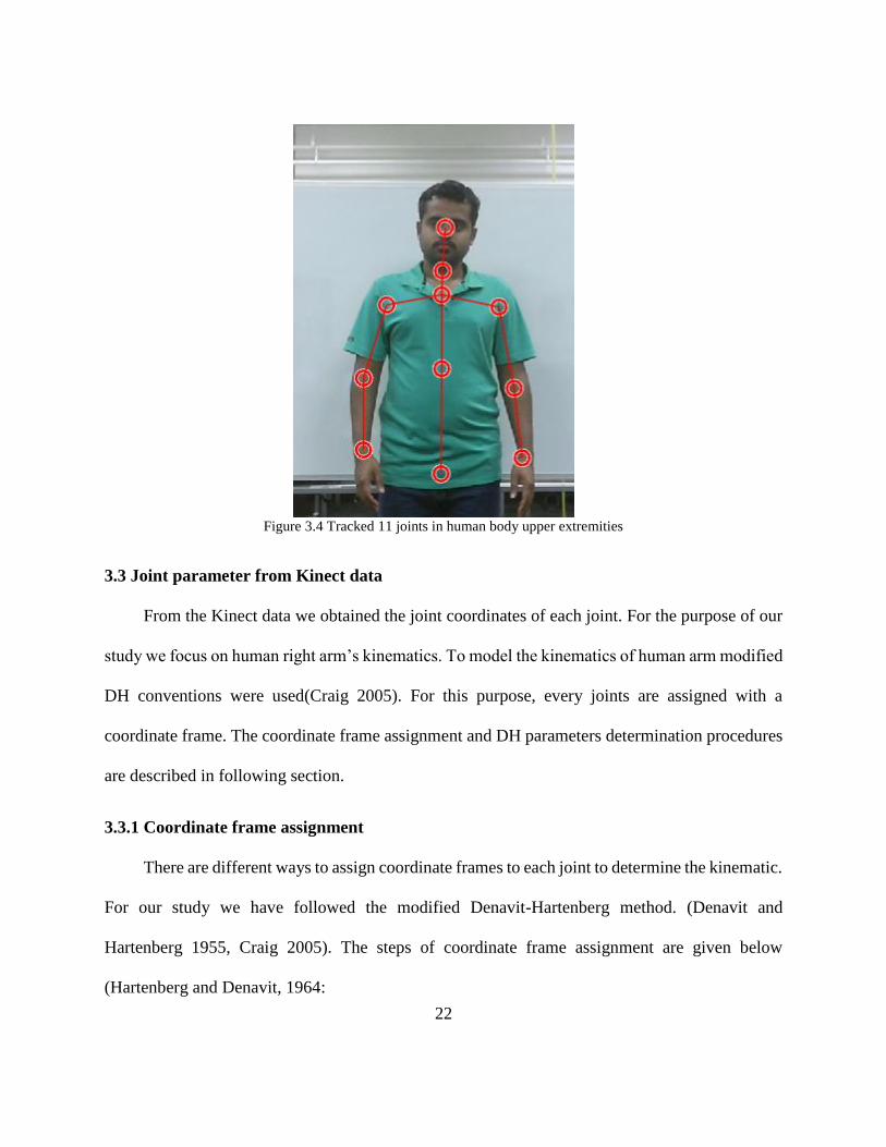
Figure 3.4 Tracked 11 joints in human body upper extremities
3.3 Joint parameter from Kinect data
From the Kinect data we obtained the joint coordinates of each joint. For the purpose of our
study we focus on human right arm’s kinematics. To model the kinematics of human arm modified
DH conventions were used(Craig 2005). For this purpose, every joints are assigned with a
coordinate frame. The coordinate frame assignment and DH parameters determination procedures
are described in following section.
3.3.1 Coordinate frame assignment
There are different ways to assign coordinate frames to each joint to determine the kinematic.
For our study we have followed the modified Denavit-Hartenberg method. (Denavit and
Hartenberg 1955, Craig 2005). The steps of coordinate frame assignment are given below
(Hartenberg and Denavit, 1964:
23
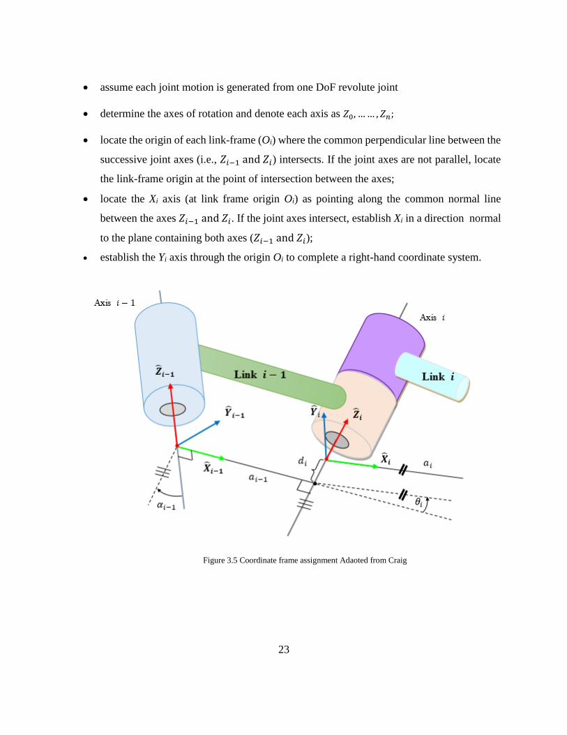
• assume each joint motion is generated from one DoF revolute joint
• determine the axes of rotation and denote each axis as 𝑍0, …… , 𝑍𝑛;
• locate the origin of each link-frame (Oi) where the common perpendicular line between the
successive joint axes (i.e., 𝑍𝑖−1 and 𝑍𝑖) intersects. If the joint axes are not parallel, locate
the link-frame origin at the point of intersection between the axes;
• locate the Xi axis (at link frame origin Oi) as pointing along the common normal line
between the axes 𝑍𝑖−1 and 𝑍𝑖. If the joint axes intersect, establish Xi in a direction normal
to the plane containing both axes (𝑍𝑖−1 and 𝑍𝑖);
• establish the Yi axis through the origin Oi to complete a right-hand coordinate system.
Figure 3.5 Coordinate frame assignment Adaoted from Craig
24
3.3.2 D-H parameters
A link of a robot can be described by four parameters (two parameters for describing the link
itself and other two for describing the link’s relation to a neighboring link) if we assign the co-
ordinate frames as described above (Denavit and Hartenberg, 1955). These parameters are known
as Denavit-Hartenberg (DH) parameters. The definitions of the DH parameters are given below
(Hartenberg and Denavit, 1964):
Link Length (ai) : the length measured along Xi, from axis Zi to axis Zi+1;
Link Twist (αi) : the angle measured about Xi, from axis Zi to axis Zi+1;
Link Offset (di) : the distance measured along the axis Zi; from Xi-1 to Xi, and
Joint Angle (θi) : the angle measured about Zi, from Xi-1 to Xi
To obtain the DH parameters, we assume that the co-ordinate frames (i.e., the link-frames which
map between the successive axes of rotation) coincide with the joint axes of rotation and have the
same order, i.e., frame coincides with joint 1, frame {2} with joint 2, and so on.
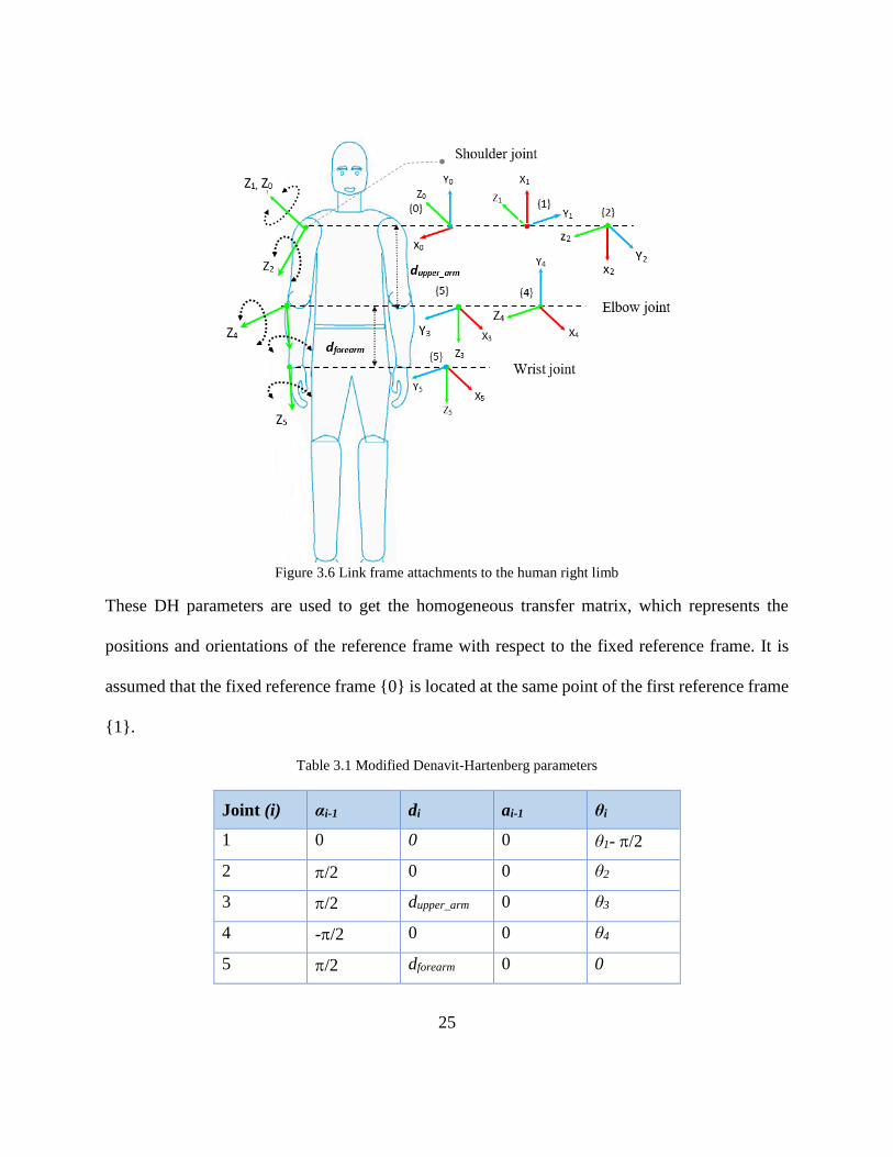
As shown in Figure 3.2, the joint axes of rotation of the human right upper limb are indicated by
dark black arrow heads (i.e., Zi). In this model, joints 1, and 2 together constitute the shoulder
joint, where joint 1 corresponds to abduction/adduction joint 2 represents vertical
flexion/extension, joint 3 corresponds to internal/external rotation of the shoulder joint and joint 4
represents the flexion/extension of the elbow joint. The elbow joint is located at a distance dupper_arm
and wrist joint is located at a distance dforearm. The modified DH parameters corresponding to the
placement of the link frames (in Figure 3.5) are summarized in Table 4.1.
25
Figure 3.6 Link frame attachments to the human right limb
These DH parameters are used to get the homogeneous transfer matrix, which represents the
positions and orientations of the reference frame with respect to the fixed reference frame. It is
assumed that the fixed reference frame {0} is located at the same point of the first reference frame
{1}.
Table 3.1 Modified Denavit-Hartenberg parameters
Joint (i) αi-1 di ai-1 θi
1 0 0 0 θ1- /2
2 /2 0 0 θ2
3 /2 dupper_arm 0 θ3
4 -/2 0 0 θ4
5 /2 dforearm 0 0
26
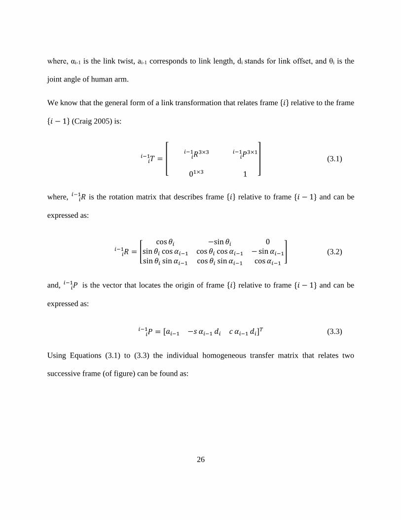
where, αi-1 is the link twist, ai-1 corresponds to link length, di stands for link offset, and θi is the
joint angle of human arm.
We know that the general form of a link transformation that relates frame {𝑖} relative to the frame
{𝑖 − 1} (Craig 2005) is:
𝑇𝑖𝑖−1 = [
𝑅𝑖𝑖−1 3×3 𝑃𝑖
𝑖−1 3×1
01×3 1
] (3.1)
where, 𝑅𝑖𝑖−1 is the rotation matrix that describes frame {𝑖} relative to frame {𝑖 − 1} and can be
expressed as:
and, 𝑃𝑖𝑖−1 is the vector that locates the origin of frame {𝑖} relative to frame {𝑖 − 1} and can be
expressed as:
Using Equations (3.1) to (3.3) the individual homogeneous transfer matrix that relates two
successive frame (of figure) can be found as:
𝑅𝑖𝑖−1 = [
cos 𝜃𝑖 −sin 𝜃𝑖 0sin 𝜃𝑖 cos 𝛼𝑖−1 cos 𝜃𝑖 cos 𝛼𝑖−1 −sin𝛼𝑖−1
sin 𝜃𝑖 sin 𝛼𝑖−1 cos 𝜃𝑖 sin 𝛼𝑖−1 cos 𝛼𝑖−1
] (3.2)
𝑃𝑖𝑖−1 = [𝑎𝑖−1 −𝑠 𝛼𝑖−1 𝑑𝑖 𝑐 𝛼𝑖−1 𝑑𝑖]
𝑇 (3.3)
27
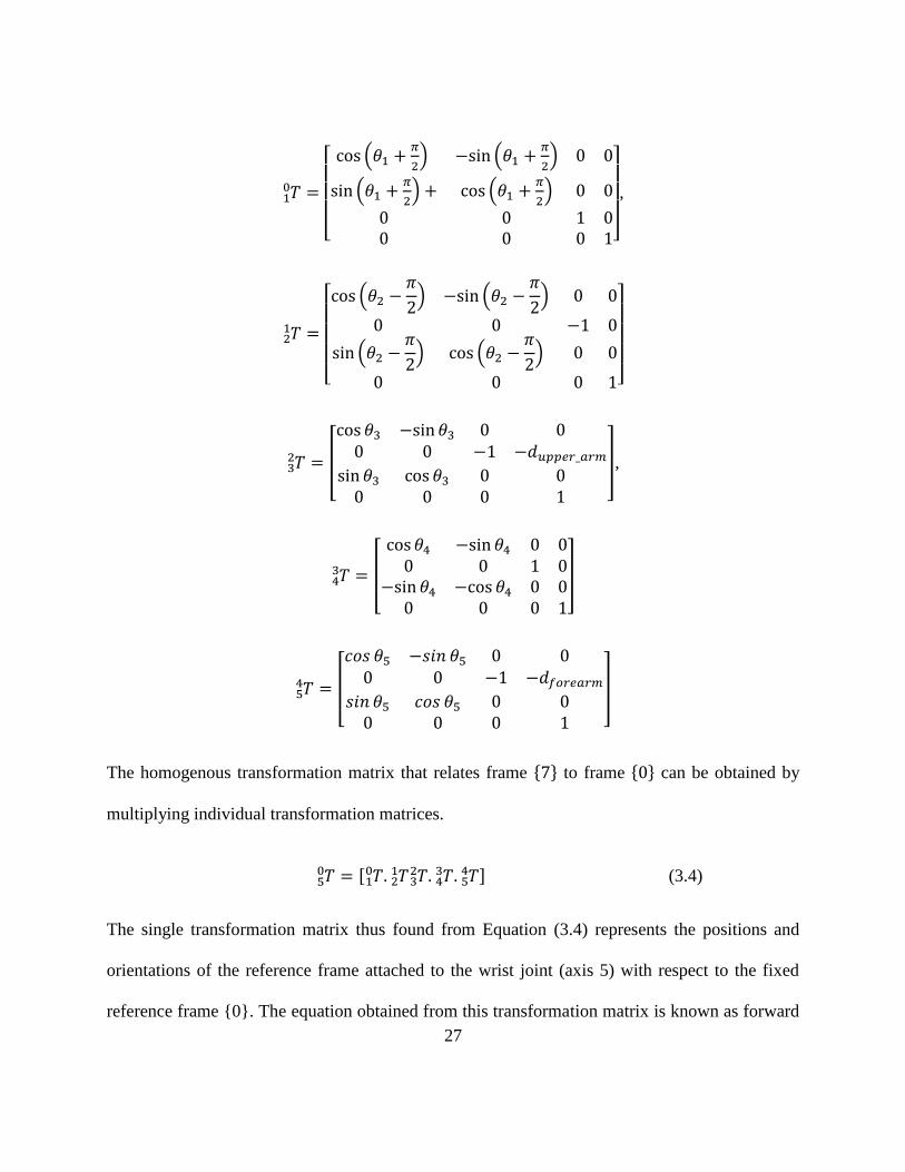
The homogenous transformation matrix that relates frame {7} to frame {0} can be obtained by
multiplying individual transformation matrices.
The single transformation matrix thus found from Equation (3.4) represents the positions and
orientations of the reference frame attached to the wrist joint (axis 5) with respect to the fixed
reference frame {0}. The equation obtained from this transformation matrix is known as forward
𝑇10 =
[ cos (𝜃1 +
𝜋
2) −sin (𝜃1 +
𝜋
2) 0 0
sin (𝜃1 +𝜋
2) + cos (𝜃1 +
𝜋
2) 0 0
0 0 1 00 0 0 1]
,
𝑇21 =
[ cos (𝜃2 −
𝜋
2) −sin (𝜃2 −
𝜋
2) 0 0
0 0 −1 0
sin (𝜃2 −𝜋
2) cos (𝜃2 −
𝜋
2) 0 0
0 0 0 1]
𝑇32 = [
cos 𝜃3 −sin 𝜃3 0 00 0 −1 −𝑑𝑢𝑝𝑝𝑒𝑟_𝑎𝑟𝑚
sin 𝜃3 cos 𝜃3 0 00 0 0 1
],
𝑇43 = [
cos 𝜃4 −sin 𝜃4 0 00 0 1 0
−sin 𝜃4 −cos 𝜃4 0 00 0 0 1
]
𝑇54 = [
𝑐𝑜𝑠 𝜃5 −𝑠𝑖𝑛 𝜃5 0 00 0 −1 −𝑑𝑓𝑜𝑟𝑒𝑎𝑟𝑚
𝑠𝑖𝑛 𝜃5 𝑐𝑜𝑠 𝜃5 0 00 0 0 1
]
𝑇50 = [ 𝑇. 𝑇 𝑇.3
221 𝑇.4
3 𝑇54
10 ] (3.4)
28
kinematics equation. If the joint variable of each joint (𝜃1, 𝜃2, 𝜃3 and 𝜃4) is given then from this
forward kinematics equation the position of list frame can be determined.
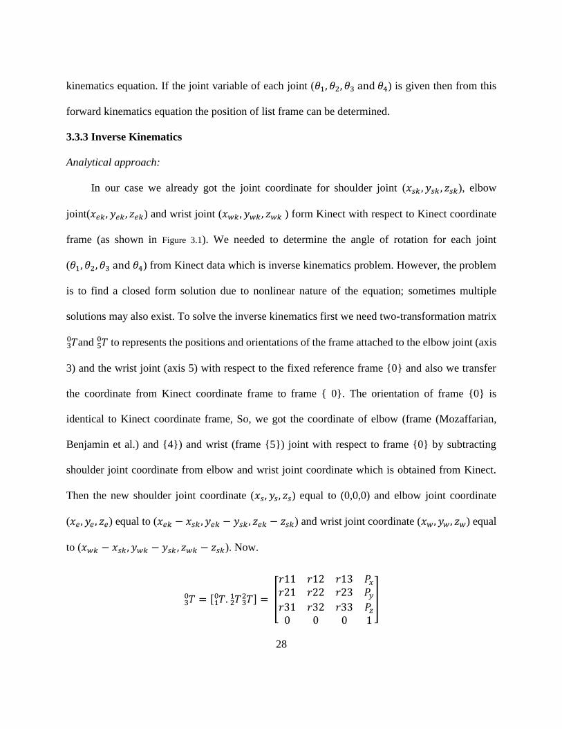
3.3.3 Inverse Kinematics
Analytical approach:
In our case we already got the joint coordinate for shoulder joint (𝑥𝑠𝑘 , 𝑦𝑠𝑘 , 𝑧𝑠𝑘), elbow
joint(𝑥𝑒𝑘, 𝑦𝑒𝑘, 𝑧𝑒𝑘) and wrist joint (𝑥𝑤𝑘, 𝑦𝑤𝑘, 𝑧𝑤𝑘 ) form Kinect with respect to Kinect coordinate
frame (as shown in Figure 3.1). We needed to determine the angle of rotation for each joint
(𝜃1, 𝜃2, 𝜃3 and 𝜃4) from Kinect data which is inverse kinematics problem. However, the problem
is to find a closed form solution due to nonlinear nature of the equation; sometimes multiple
solutions may also exist. To solve the inverse kinematics first we need two-transformation matrix
𝑇30 and 𝑇5
0 to represents the positions and orientations of the frame attached to the elbow joint (axis
3) and the wrist joint (axis 5) with respect to the fixed reference frame {0} and also we transfer
the coordinate from Kinect coordinate frame to frame { 0}. The orientation of frame {0} is
identical to Kinect coordinate frame, So, we got the coordinate of elbow (frame (Mozaffarian,
Benjamin et al.) and {4}) and wrist (frame {5}) joint with respect to frame {0} by subtracting
shoulder joint coordinate from elbow and wrist joint coordinate which is obtained from Kinect.
Then the new shoulder joint coordinate (𝑥𝑠, 𝑦𝑠, 𝑧𝑠) equal to (0,0,0) and elbow joint coordinate
(𝑥𝑒 , 𝑦𝑒 , 𝑧𝑒) equal to (𝑥𝑒𝑘 − 𝑥𝑠𝑘 , 𝑦𝑒𝑘 − 𝑦𝑠𝑘 , 𝑧𝑒𝑘 − 𝑧𝑠𝑘) and wrist joint coordinate (𝑥𝑤, 𝑦𝑤, 𝑧𝑤) equal
to (𝑥𝑤𝑘 − 𝑥𝑠𝑘, 𝑦𝑤𝑘 − 𝑦𝑠𝑘 , 𝑧𝑤𝑘 − 𝑧𝑠𝑘). Now.
𝑇30 = [ 𝑇. 𝑇 𝑇3
221
10 ] = [
𝑟11 𝑟12 𝑟13 𝑃𝑥
𝑟21 𝑟22 𝑟23 𝑃𝑦
𝑟31 𝑟32 𝑟33 𝑃𝑧
0 0 0 1
]
29
Where, 𝑃𝑥 = 𝑑𝑢𝑝𝑝𝑒𝑟𝑎𝑟𝑚cos(𝜃1 + 𝜋
2⁄ ) sin(𝜃2 − 𝜋2⁄ ) (3.6)
𝑃𝑦 = 𝑑𝑢𝑝𝑝𝑒𝑟𝑎𝑟𝑚sin(𝜃1 + 𝜋
2⁄ ) sin(𝜃2 − 𝜋2⁄ ) (3.7)
𝑃𝑧 = − 𝑑𝑢𝑝𝑝𝑒𝑟𝑎𝑟𝑚cos(𝜃2 − 𝜋
2⁄ ) (3.8)
Here, (𝑃𝑥, 𝑃𝑦, 𝑃𝑧) represents the elbow joint coordinate (𝑥𝑒 , 𝑦𝑒 , 𝑧𝑒).
𝑥𝑒 = 𝑑𝑢𝑝𝑝𝑒𝑟_𝑎𝑟𝑚 cos(𝜃1 + 𝜋2⁄ ) sin(𝜃2 − 𝜋
2⁄ ) (3.9)
𝑦𝑒 = 𝑑𝑢𝑝𝑝𝑒𝑟_𝑎𝑟𝑚 sin(𝜃1 + 𝜋2⁄ ) sin(𝜃2 − 𝜋
2⁄ ) (3.10)
𝑧𝑒 = − 𝑑𝑢𝑝𝑝𝑒𝑟_𝑎𝑟𝑚 cos(𝜃2 − 𝜋2⁄ ) (3.11)
Again, from
𝑇50 = [ 𝑇. 𝑇 𝑇.3
221 𝑇.4
3 𝑇54
10 ] = [
𝑟11 𝑟12 𝑟13 𝑃𝑥
𝑟21 𝑟22 𝑟23 𝑃𝑦
𝑟31 𝑟32 𝑟33 𝑃𝑧
0 0 0 1
]
Where,
𝑃𝑥 = 𝑑𝑓𝑜𝑟𝑒𝑎𝑟𝑚(sin 𝜃4 sin 𝜃3 sin(𝜃1 + 𝜋2⁄ ) + cos 𝜃3 cos(𝜃1 + 𝜋
2⁄ ) cos(𝜃2 − 𝜋2⁄ )
+ cos 𝜃4 cos(𝜃1 + 𝜋2⁄ ) sin(𝜃2 − 𝜋
2⁄ ))
− 𝑑𝑢𝑝𝑝𝑒𝑟_𝑎𝑟𝑚 cos(𝜃1 + 𝜋2⁄ ) sin(𝜃2 − 𝜋
2⁄ ) (3.12)
𝑃𝑦 = 𝑑𝑢𝑝𝑝𝑒𝑟_𝑎𝑟𝑚 sin(𝜃1 + 𝜋2⁄ ) sin(𝜃2 − 𝜋
2⁄ )
− 𝑑𝑓𝑜𝑟𝑒𝑎𝑟𝑚(sin 𝜃4 cos(𝜃1 + 𝜋2⁄ ) sin 𝜃3 − cos 𝜃3 cos(𝜃2 − 𝜋
2⁄ ) sin(𝜃1 + 𝜋2⁄ )
− cos 𝜃4 sin(𝜃1 + 𝜋2⁄ ) sin(𝜃2 − 𝜋
2⁄ )) (3.13)
30
𝑃𝑧 = − 𝑑𝑓𝑜𝑟𝑒𝑎𝑟𝑚(cos 𝜃4 cos(𝜃2 − 𝜋2⁄ ) − cos 𝜃3 sin 𝜃4 sin(𝜃2 − 𝜋
2⁄ ))
− 𝑑𝑢𝑝𝑝𝑒𝑟_𝑎𝑟𝑚 cos(𝜃2 − 𝜋2⁄ ) (3.14)
Here, (𝑃𝑥, 𝑃𝑦, 𝑃𝑧) represents the elbow joint coordinate (𝑥𝑤, 𝑦𝑤 , 𝑧𝑤).
𝑥𝑤 = 𝑑𝑓𝑜𝑟𝑒𝑎𝑟𝑚(sin 𝜃4 sin 𝜃3 sin(𝜃1 + 𝜋2⁄ ) + cos 𝜃3 cos(𝜃1 + 𝜋
2⁄ ) cos(𝜃2 − 𝜋2⁄ )
+ cos 𝜃4 cos(𝜃1 + 𝜋2⁄ ) sin(𝜃2 − 𝜋
2⁄ ))
− 𝑑𝑢𝑝𝑝𝑒𝑟_𝑎𝑟𝑚 cos(𝜃1 + 𝜋2⁄ ) sin(𝜃2 − 𝜋
2⁄ ) (3.15)
𝑦𝑤 = 𝑑𝑢𝑝𝑝𝑒𝑟_𝑎𝑟𝑚 sin(𝜃1 + 𝜋2⁄ ) sin(𝜃2 − 𝜋
2⁄ )
− 𝑑𝑓𝑜𝑟𝑒𝑎𝑟𝑚(sin 𝜃4 cos(𝜃1 + 𝜋2⁄ ) sin 𝜃3 − cos 𝜃3 cos(𝜃2 − 𝜋
2⁄ ) sin(𝜃1 + 𝜋2⁄ )
− cos 𝜃4 sin(𝜃1 + 𝜋2⁄ ) sin(𝜃2 − 𝜋
2⁄ )) (3.16)
𝑧𝑤 = − 𝑑𝑓𝑜𝑟𝑒𝑎𝑟𝑚(cos 𝜃4 cos(𝜃2 − 𝜋2⁄ ) − cos 𝜃3 sin 𝜃4 sin(𝜃2 − 𝜋
2⁄ ))
− 𝑑𝑢𝑝𝑝𝑒𝑟_𝑎𝑟𝑚 cos(𝜃2 − 𝜋2⁄ ) (3.17)
Equation (3.9), (3.10), (3.11), (3.15), (3.16) and (3.17) are our inverse kinematic analytical
equation. There is four unknown but we have six equation, which are highly nonlinear and difficult
to solve. To simplify the calculation we determine the joint angle 𝜃4 geometrically using cosine
rule.
31
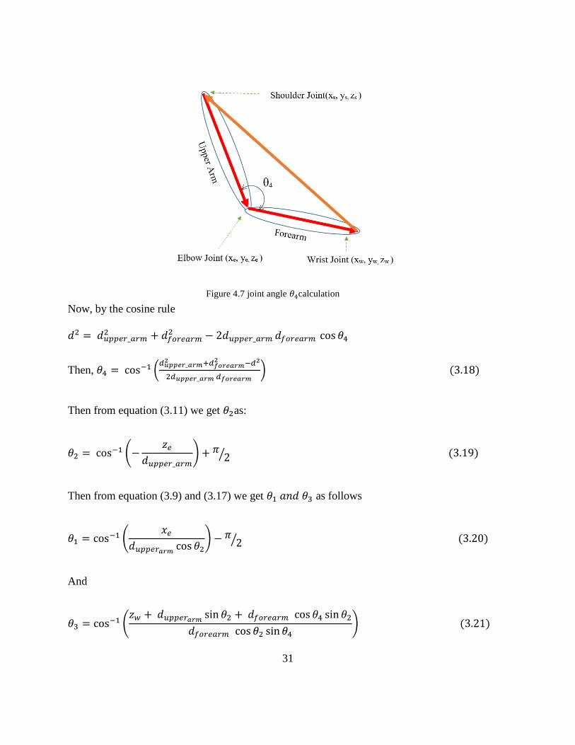
Now, by the cosine rule
𝑑2 = 𝑑𝑢𝑝𝑝𝑒𝑟_𝑎𝑟𝑚2 + 𝑑𝑓𝑜𝑟𝑒𝑎𝑟𝑚
2 − 2𝑑𝑢𝑝𝑝𝑒𝑟_𝑎𝑟𝑚 𝑑𝑓𝑜𝑟𝑒𝑎𝑟𝑚 cos 𝜃4
Then, 𝜃4 = cos−1 (𝑑𝑢𝑝𝑝𝑒𝑟_𝑎𝑟𝑚
2 +𝑑𝑓𝑜𝑟𝑒𝑎𝑟𝑚2 −𝑑2
2𝑑𝑢𝑝𝑝𝑒𝑟_𝑎𝑟𝑚 𝑑𝑓𝑜𝑟𝑒𝑎𝑟𝑚 ) (3.18)
Then from equation (3.11) we get 𝜃2as:
𝜃2 = cos−1 (−𝑧𝑒
𝑑𝑢𝑝𝑝𝑒𝑟_𝑎𝑟𝑚) + 𝜋
2⁄ (3.19)
Then from equation (3.9) and (3.17) we get 𝜃1 𝑎𝑛𝑑 𝜃3 as follows
𝜃1 = cos−1 (𝑥𝑒
𝑑𝑢𝑝𝑝𝑒𝑟𝑎𝑟𝑚cos 𝜃2
) − 𝜋2⁄ (3.20)
And
𝜃3 = cos−1 (𝑧𝑤 + 𝑑𝑢𝑝𝑝𝑒𝑟𝑎𝑟𝑚
sin 𝜃2 + 𝑑𝑓𝑜𝑟𝑒𝑎𝑟𝑚 cos 𝜃4 sin 𝜃2
𝑑𝑓𝑜𝑟𝑒𝑎𝑟𝑚 cos 𝜃2 sin 𝜃4) (3.21)
Figure 4.7 joint angle 𝜃4calculation
32
By using equation (3.18), (3.19), (3.20) and (3.21) we got all four joint angle.
However, solving this inverse kinematics equations generate singularity effect specially if 𝜃2or
𝜃4any of them goes to zero degree position then 𝜃1 and 𝜃3 become infinity. Solving this singularity
cause high computation and reduce the program execution performance. For the reason we found
alternative geometric solution which is much easier to compute and reliable.
Geometric approach
Determination of angle 𝜃4geometrically already discussed in previous section. Now the solution
for others angle need some extra consideration.
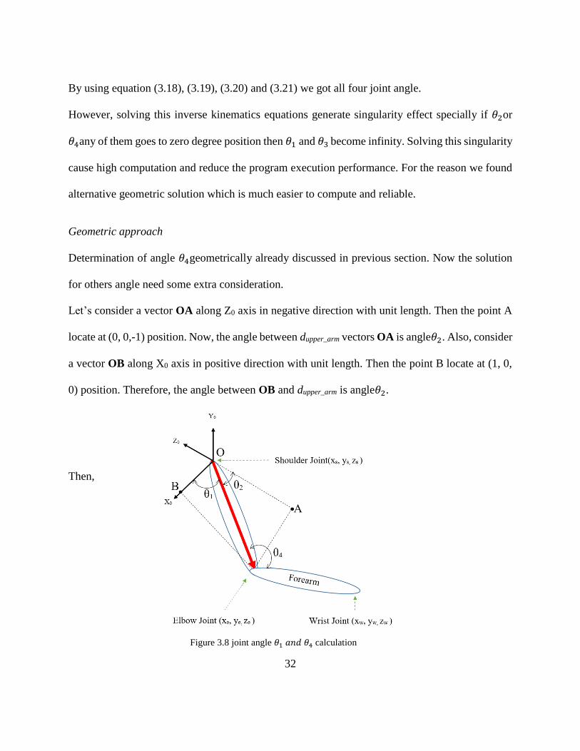
Let’s consider a vector OA along Z0 axis in negative direction with unit length. Then the point A
locate at (0, 0,-1) position. Now, the angle between dupper_arm vectors OA is angle𝜃2. Also, consider
a vector OB along X0 axis in positive direction with unit length. Then the point B locate at (1, 0,
0) position. Therefore, the angle between OB and dupper_arm is angle𝜃2.
Then,
Figure 3.8 joint angle 𝜃1 𝑎𝑛𝑑 𝜃4 calculation
33
cos 𝜃1 = √(1 − 0)2 + (0 − 0)2 + (0 − 0)2 + 𝑑𝑢𝑝𝑝𝑒𝑟𝑎𝑟𝑚
− √(𝑥𝑒 − 1)2 + (𝑦𝑒)2+(𝑧𝑒)2
𝑑𝑢𝑝𝑝𝑒𝑟𝑎𝑟𝑚
And sin 𝜃1 = ±√1 − (cos 𝜃1)2
Therefore, 𝜃1 = tan−1 (± sin𝜃1
cos𝜃1)
Similarly,
cos 𝜃2 = √(0 − 0)2 + (0 − 0)2 + (−1 − 0)2 + 𝑑𝑢𝑝𝑝𝑒𝑟𝑎𝑟𝑚
− √(𝑥𝑒)2 + (𝑦𝑒)2+(𝑧𝑒 + 1)2
𝑑𝑢𝑝𝑝𝑒𝑟𝑎𝑟𝑚
And sin 𝜃2 = ±√1 − (cos 𝜃2)2
Therefore, 𝜃2 = tan−1 (± sin𝜃2
cos𝜃2)
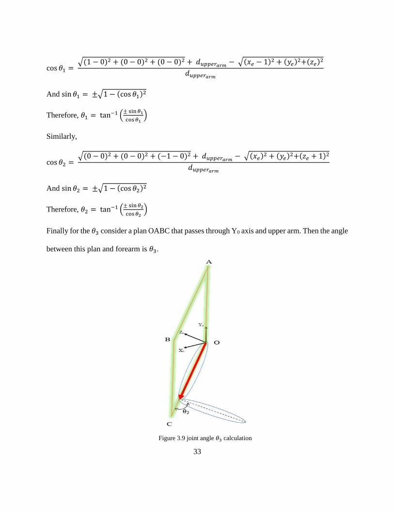
Finally for the 𝜃3 consider a plan OABC that passes through Y0 axis and upper arm. Then the angle
between this plan and forearm is 𝜃3.
Figure 3.9 joint angle 𝜃3 calculation
34
sin 𝜃3 = 𝑧𝑒(𝑥𝑤−𝑥𝑒) − 𝑥𝑒(𝑧𝑤 − 𝑧𝑒)
√𝑧𝑒2 + 𝑥𝑒
2√(𝑥𝑤 − 𝑥𝑒)2 + (𝑦𝑤 − 𝑦𝑒)2 + (𝑧𝑤 − 𝑧𝑒)2
And cos 𝜃3 = ±√1 − (sin 𝜃3)2
Therefore, 𝜃3 = tan−1 (± sin𝜃3
cos𝜃3)
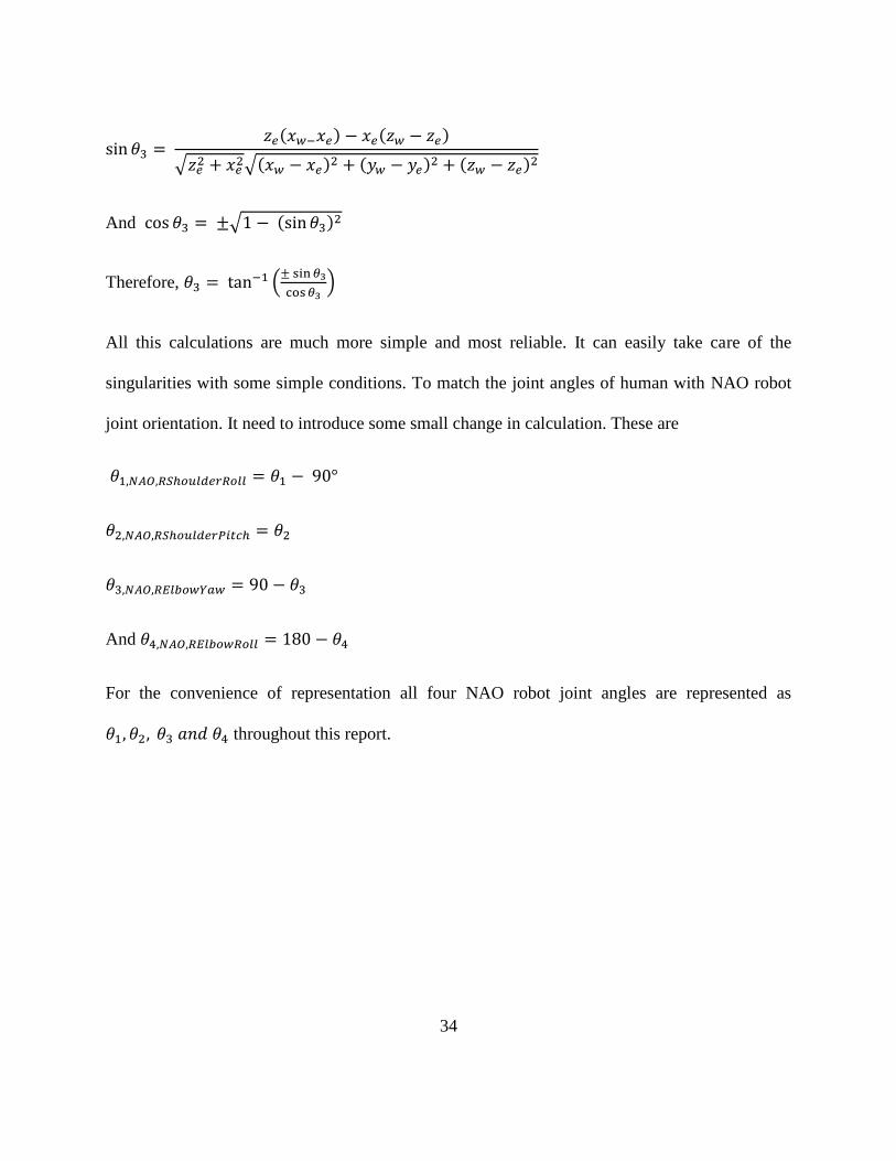
All this calculations are much more simple and most reliable. It can easily take care of the
singularities with some simple conditions. To match the joint angles of human with NAO robot
joint orientation. It need to introduce some small change in calculation. These are
𝜃1,𝑁𝐴𝑂,𝑅𝑆ℎ𝑜𝑢𝑙𝑑𝑒𝑟𝑅𝑜𝑙𝑙 = 𝜃1 − 90°
𝜃2,𝑁𝐴𝑂,𝑅𝑆ℎ𝑜𝑢𝑙𝑑𝑒𝑟𝑃𝑖𝑡𝑐ℎ = 𝜃2
𝜃3,𝑁𝐴𝑂,𝑅𝐸𝑙𝑏𝑜𝑤𝑌𝑎𝑤 = 90 − 𝜃3
And 𝜃4,𝑁𝐴𝑂,𝑅𝐸𝑙𝑏𝑜𝑤𝑅𝑜𝑙𝑙 = 180 − 𝜃4
For the convenience of representation all four NAO robot joint angles are represented as
𝜃1, 𝜃2, 𝜃3 𝑎𝑛𝑑 𝜃4 throughout this report.
35
CHAPTER 4
NAO’S REHABILITATION LIBRARY (NRL)
This chapter focuses on Aim-1. To demonstrate rehabilitation exercises with NAO, a library
of recommended rehabilitation exercises involving shoulder and elbow joint movements (2011)
was formed in Choregraphe (graphical programming interface) (Group 2013). In experiments,
NAO was maneuvered to instruct and demonstrate the exercises from the NRL. The first section
of this chapter briefly describes the Choregraphe programming interface. In the mid sections of
the chapter, experimental results with NAO are presented. The chapter ends with a brief discussion
on the experimental results.
4.1 Choregraphe
Choregraphe is high level programming interface for NAO robot. It provides different robot
functionality as blocks (as shown in Figure 4.3). Blocks contain in a blocks library. Using these
blocks, it is possible to build a very complex behavior for NAO. Choregraphe built-in blocks
provide access to all sensors and actuators of NAO. In addition, bocks are used to access in NAO’s
memory. It is also possible to build a new functional block in Choregraphe using programming
language Python with the provided SDK. Choregraphe also provides a virtual NAO in which one
can perform simulation of created behaviors. Choregraphe contains different types of blocks.
Audio, vision, motion, sensing etc.
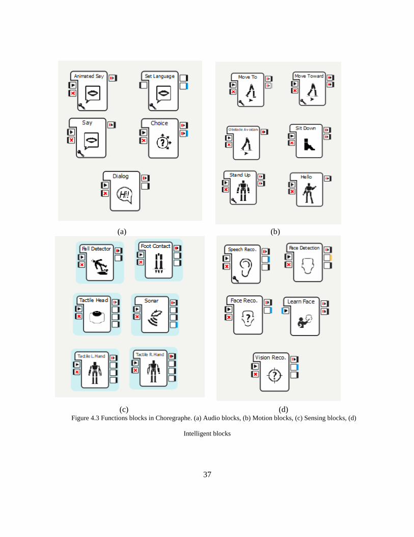
Figure 4.3 presents some commonly used functional blocks in Choregraphe. Audio blocks
as shown in Figure 4.3(a) have some specific functionality. For instance, using the ‘Say’ block a
program can be made so that NAO can speak the text contained in the ‘Say’ block. Figure 4.3(b)
contains some basic motion blocks by which NAO can move in any direction, can sit or stand, can
36
waives hands etc. Choregraphe also provides access to NAO’s sensors by using the sensing blocks
library (Figure 4.3 (c)). There has also some advanced built-in blocks in Choregraphe such as
speech recognition, face recognition, learning face, detect face etc.
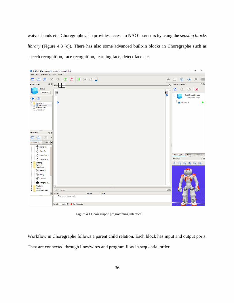
Workflow in Choregraphe follows a parent child relation. Each block has input and output ports.
They are connected through lines/wires and program flow in sequential order.
Figure 4.1 Choregraphe programming interface
37
(a) (b)
(c) (d) Figure 4.3 Functions blocks in Choregraphe. (a) Audio blocks, (b) Motion blocks, (c) Sensing blocks, (d)
Intelligent blocks
38
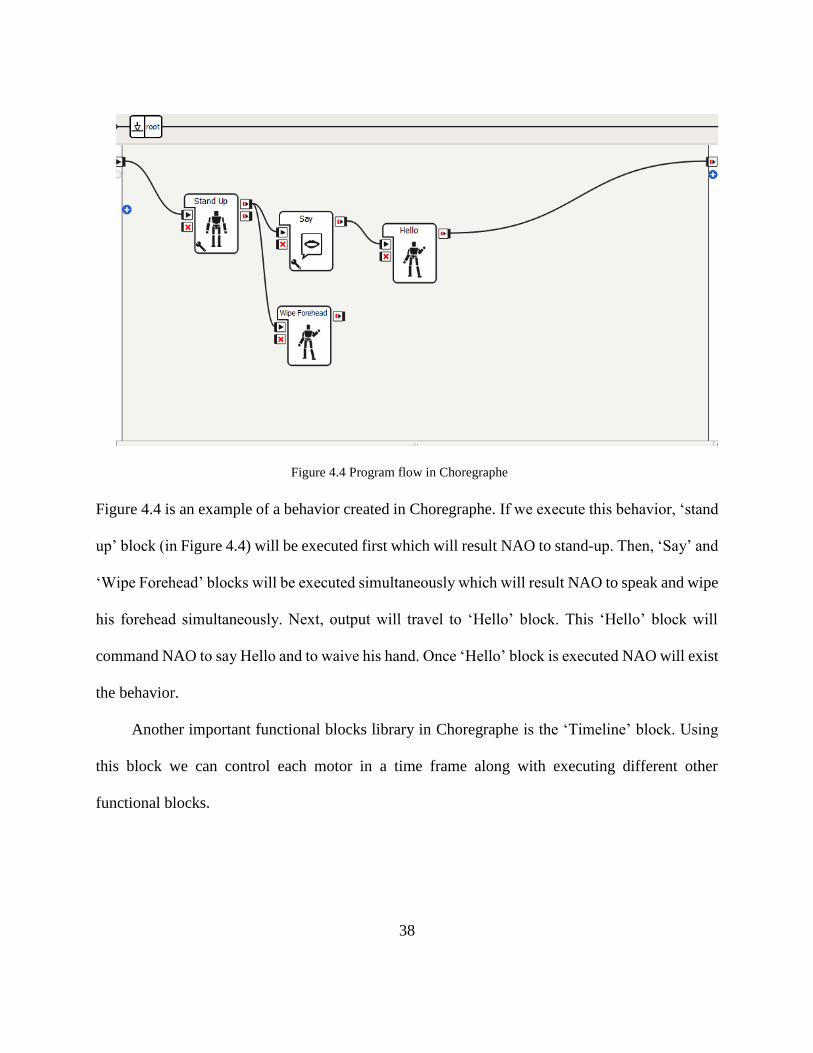
Figure 4.4 is an example of a behavior created in Choregraphe. If we execute this behavior, ‘stand
up’ block (in Figure 4.4) will be executed first which will result NAO to stand-up. Then, ‘Say’ and
‘Wipe Forehead’ blocks will be executed simultaneously which will result NAO to speak and wipe
his forehead simultaneously. Next, output will travel to ‘Hello’ block. This ‘Hello’ block will
command NAO to say Hello and to waive his hand. Once ‘Hello’ block is executed NAO will exist
the behavior.
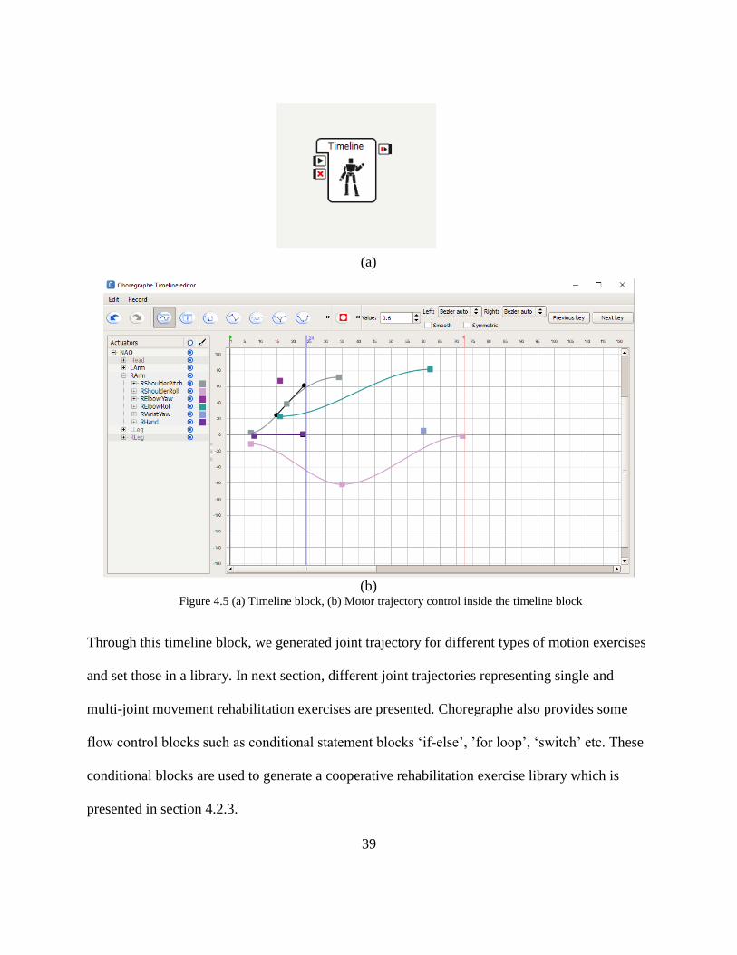
Another important functional blocks library in Choregraphe is the ‘Timeline’ block. Using
this block we can control each motor in a time frame along with executing different other
functional blocks.
Figure 4.4 Program flow in Choregraphe
39
(a)
(b) Figure 4.5 (a) Timeline block, (b) Motor trajectory control inside the timeline block
Through this timeline block, we generated joint trajectory for different types of motion exercises
and set those in a library. In next section, different joint trajectories representing single and
multi-joint movement rehabilitation exercises are presented. Choregraphe also provides some
flow control blocks such as conditional statement blocks ‘if-else’, ’for loop’, ‘switch’ etc. These
conditional blocks are used to generate a cooperative rehabilitation exercise library which is
presented in section 4.2.3.
40
4.2 NAO’s Rehabilitation Library (NRL)
The exercises formed in NRL can be grouped under three categories; ‘single joint
movement’, ‘multi joint movements’, and ‘co-operative exercise’. NAO will instruct and
demonstrate subjects to perform those exercises. A typical NAO’s instruction is given below:
{
NAO: Hello friend,
NAO: Let’s get ready. Stay normal and don’t worry. I am here for you mate. Believe me
it’s going to be fun.
NAO: Anyway, we will do some exercise together
NAO: In this session, I will show you how to do elbow flexion/extension exercise in a
minute. After that you will be asked to do perform the exercise…
⁞
}
4.2.1 Single joint movements
Single joint movement exercises in NRL include shoulder joint abduction/adduction,
shoulder joint vertical flexion/extension, shoulder joint internal/external rotation, and elbow joint
flexion/extension motion. Since NAO does not have wrist joint flexion/extension and radial/ulnar
deviation we have excluded wrist joint motions from this study.
• Shoulder joint movements
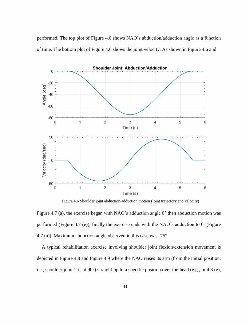
Figure 4.6 shows the experimental results of shoulder joint abduction/adduction where a
coordinated movement of shoulder horizontal and vertical flexion/extension motion were
41
performed. The top plot of Figure 4.6 shows NAO’s abduction/adduction angle as a function
of time. The bottom plot of Figure 4.6 shows the joint velocity. As shown in Figure 4.6 and
Figure 4.7 (a), the exercise began with NAO’s adduction angle 0° then abduction motion was
performed (Figure 4.7 (e)), finally the exercise ends with the NAO’s adduction to 0° (Figure
4.7 (a)). Maximum abduction angle observed in this case was -75°.
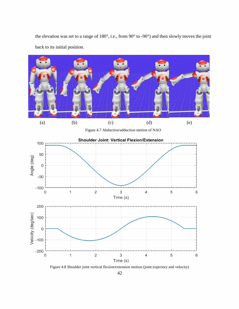
A typical rehabilitation exercise involving shoulder joint flexion/extension movement is
depicted in Figure 4.8 and Figure 4.9 where the NAO raises its arm (from the initial position,
i.e., shoulder joint-2 is at 90°) straight up to a specific position over the head (e.g., in 4.8 (e),
Figure 4.6 Shoulder joint abduction/adduction motion (joint trajectory and velocity)
42
the elevation was set to a range of 180°, i.e., from 90° to -90°) and then slowly moves the joint
back to its initial position.
(a) (b) (c) (d) (e)
Figure 4.7 Abduction/adduction motion of NAO
Figure 4.8 Shoulder joint vertical flexion/extension motion (joint trajectory and velocity)
43
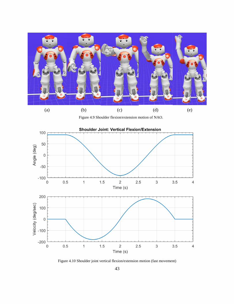
(a) (b) (c) (d) (e)
Figure 4.9 Shoulder flexion/extension motion of NAO.
Figure 4.10 Shoulder joint vertical flexion/extension motion (fast movement)
44
Depending on the subject, it is often required to change the speed of such exercises. Figure 4.10
shows the similar exercises that were performed with different speeds of motion.
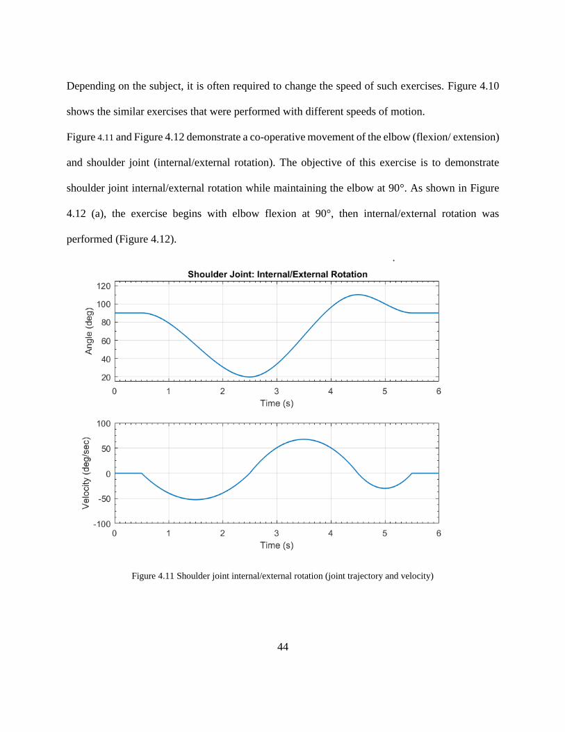
Figure 4.11 and Figure 4.12 demonstrate a co-operative movement of the elbow (flexion/ extension)
and shoulder joint (internal/external rotation). The objective of this exercise is to demonstrate
shoulder joint internal/external rotation while maintaining the elbow at 90°. As shown in Figure
4.12 (a), the exercise begins with elbow flexion at 90°, then internal/external rotation was
performed (Figure 4.12).
Figure 4.11 Shoulder joint internal/external rotation (joint trajectory and velocity)
45
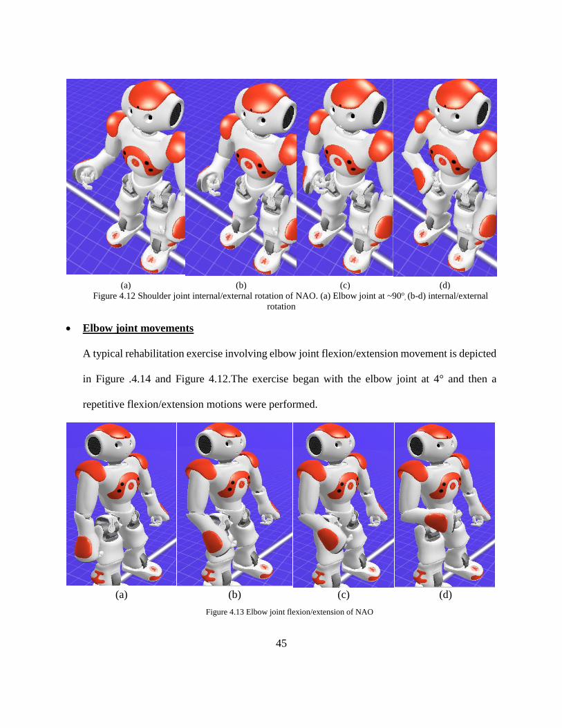
(a) (b) (c) (d)
Figure 4.12 Shoulder joint internal/external rotation of NAO. (a) Elbow joint at ~90o, (b-d) internal/external
rotation
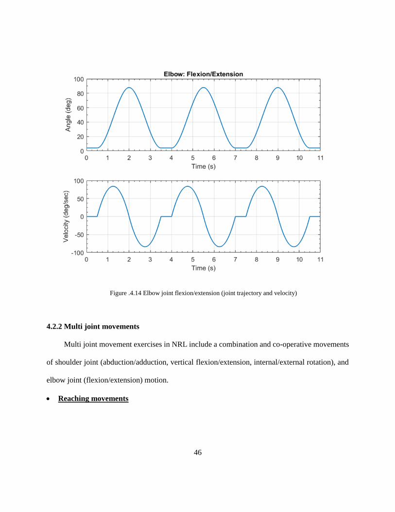
• Elbow joint movements
A typical rehabilitation exercise involving elbow joint flexion/extension movement is depicted
in Figure .4.14 and Figure 4.12.The exercise began with the elbow joint at 4° and then a
repetitive flexion/extension motions were performed.
(a) (b) (c) (d)
Figure 4.13 Elbow joint flexion/extension of NAO
46
Figure .4.14 Elbow joint flexion/extension (joint trajectory and velocity)
4.2.2 Multi joint movements
Multi joint movement exercises in NRL include a combination and co-operative movements
of shoulder joint (abduction/adduction, vertical flexion/extension, internal/external rotation), and
elbow joint (flexion/extension) motion.
• Reaching movements
47
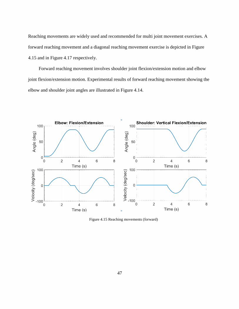
Reaching movements are widely used and recommended for multi joint movement exercises. A
forward reaching movement and a diagonal reaching movement exercise is depicted in Figure
4.15 and in Figure 4.17 respectively.
Forward reaching movement involves shoulder joint flexion/extension motion and elbow
joint flexion/extension motion. Experimental results of forward reaching movement showing the
elbow and shoulder joint angles are illustrated in Figure 4.14.
Figure 4.15 Reaching movements (forward)
48
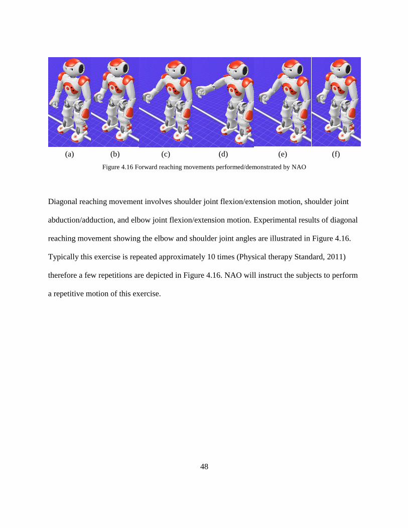
(a) (b) (c) (d) (e) (f)
Figure 4.16 Forward reaching movements performed/demonstrated by NAO
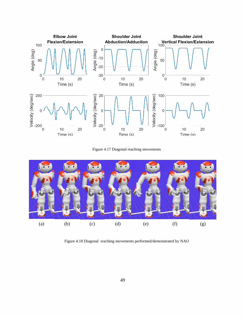
Diagonal reaching movement involves shoulder joint flexion/extension motion, shoulder joint
abduction/adduction, and elbow joint flexion/extension motion. Experimental results of diagonal
reaching movement showing the elbow and shoulder joint angles are illustrated in Figure 4.16.
Typically this exercise is repeated approximately 10 times (Physical therapy Standard, 2011)
therefore a few repetitions are depicted in Figure 4.16. NAO will instruct the subjects to perform
a repetitive motion of this exercise.
49
Figure 4.17 Diagonal reaching movements
(a) (b) (c) (d) (e) (f) (g)
Figure 4.18 Diagonal reaching movements performed/demonstrated by NAO
50
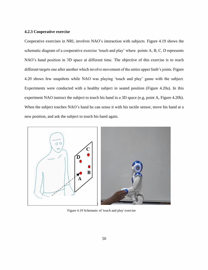
4.2.3 Cooperative exercise
Cooperative exercises in NRL involves NAO’s interaction with subjects. Figure 4.19 shows the
schematic diagram of a cooperative exercise ‘touch and play’ where points A, B, C, D represents
NAO’s hand position in 3D space at different time. The objective of this exercise is to reach
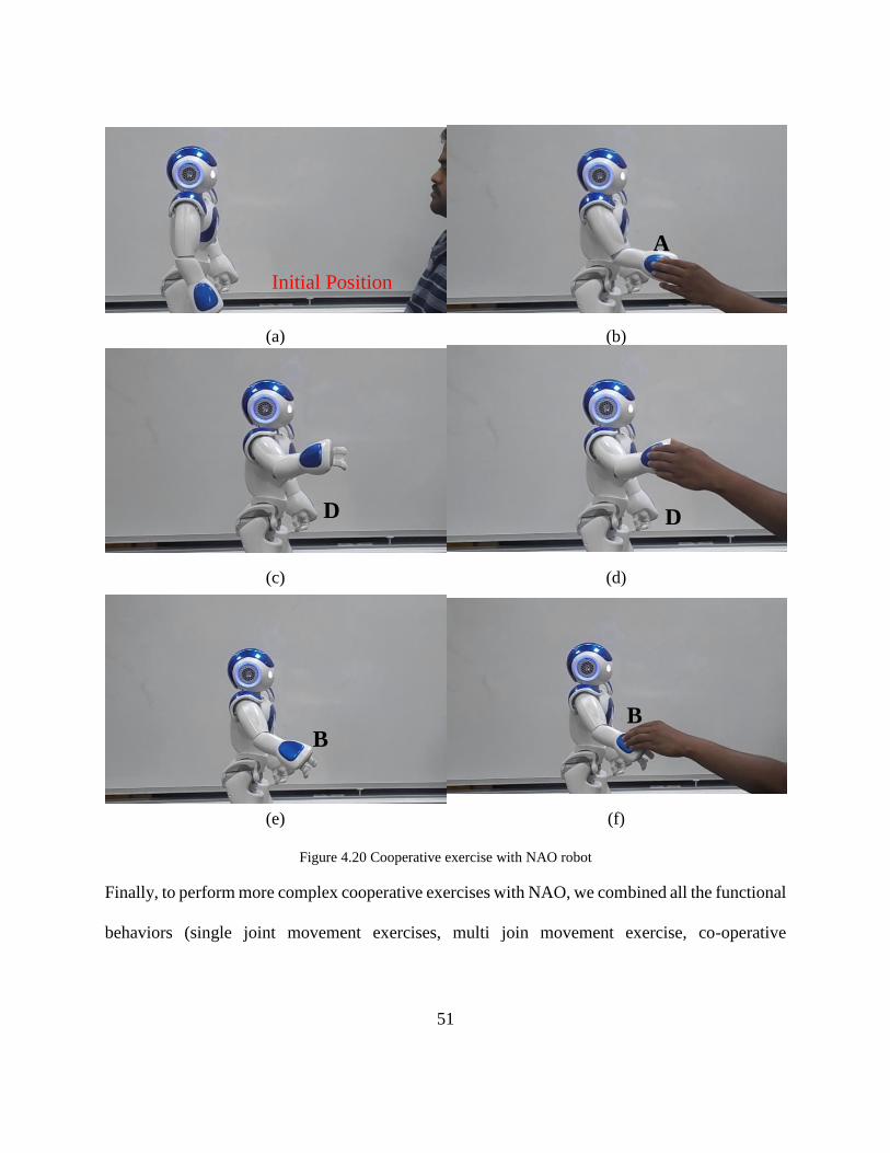
different targets one after another which involve movement of the entire upper limb’s joints. Figure
4.20 shows few snapshots while NAO was playing ‘touch and play’ game with the subject.
Experiments were conducted with a healthy subject in seated position (Figure 4.20a). In this
experiment NAO instruct the subject to touch his hand in a 3D space (e.g, point A, Figure 4.20b).
When the subject touches NAO’s hand he can sense it with his tactile sensor, move his hand at a
new position, and ask the subject to touch his hand again.
Figure 4.19 Schematic of 'touch and play' exercise
51
(a) (b)
(c) (d)
(e) (f)
Figure 4.20 Cooperative exercise with NAO robot
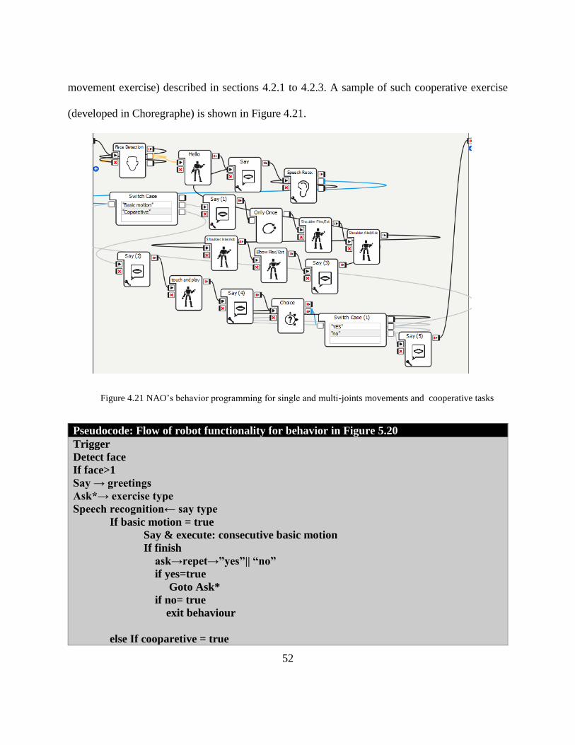
Finally, to perform more complex cooperative exercises with NAO, we combined all the functional
behaviors (single joint movement exercises, multi join movement exercise, co-operative
A
a Initial Position
D D
B B
52
movement exercise) described in sections 4.2.1 to 4.2.3. A sample of such cooperative exercise
(developed in Choregraphe) is shown in Figure 4.21.
Figure 4.21 NAO’s behavior programming for single and multi-joints movements and cooperative tasks
Pseudocode: Flow of robot functionality for behavior in Figure 5.20
Trigger
Detect face
If face>1
Say → greetings
Ask*→ exercise type
Speech recognition← say type
If basic motion = true
Say & execute: consecutive basic motion
If finish
ask→repet→”yes”|| “no”
if yes=true
Goto Ask*
if no= true
exit behaviour
else If cooparetive = true
53
Ask**→touch hand
hand tactile←yes
move→new position
if finish
ask→repet→”yes”|| “no”
if yes=true
Goto Ask**
if no= true
exit behaviour
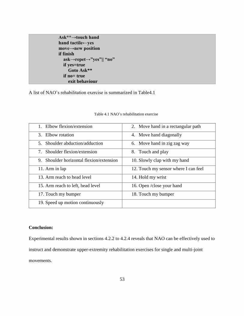
A list of NAO’s rehabilitation exercise is summarized in Table4.1
Table 4.1 NAO’s rehabilitation exercise
1. Elbow flexion/extension 2. Move hand in a rectangular path
3. Elbow rotation 4. Move hand diagonally
5. Shoulder abduction/adduction 6. Move hand in zig zag way
7. Shoulder flexion/extension 8. Touch and play
9. Shoulder horizontal flexion/extension 10. Slowly clap with my hand
11. Arm in lap 12. Touch my sensor where I can feel
13. Arm reach to head level 14. Hold my wrist
15. Arm reach to left, head level 16. Open /close your hand
17. Touch my bumper 18. Touch my bumper
19. Speed up motion continuously
Conclusion:
Experimental results shown in sections 4.2.2 to 4.2.4 reveals that NAO can be effectively used to
instruct and demonstrate upper-extremity rehabilitation exercises for single and multi-joint
movements.
54
CHAPTER 5
TELE-REHABILITATION SCHEME
This chapter focuses on Aim-2. To develop a rehabilitation scheme that utilizes the concept
of teleoperation. In the previous chapter, we built a library that contains a set of recommended
rehabilitation exercises for NAO robot, which will be performed, by NAO robot later. However,
what if it is required to introduce new exercise remotely? Teleoperation can be used to introduce
new exercises in front of the patient and a therapist can be demonstrated different rehab exercise
to different group of people at the same time remotely. Different group of people from different
place can get therapy from same therapist at the same time using tele-rehabilitation scheme. Some
stroke patient may not feel comfortable showing their disability to other people, or they may not
feel good being in front of other people. The tele-rehabilitation is a possible solution in such a
case. The first section of this chapter describes the methodology of how can NAO robot be
operated remotely using Kinect sensor. The chapter ends with the performance analysis of
teleoperation for NAO robot with Kinect sensor.
5.1 Methodology
To control the movement of the right arm of NAO robot remotely we used Kinect sensor to
generate the control signal. As described in chapter 3 from the Kinect sensor it is possible to track
human motion in front of it. The angle value obtained from the Kinect data then needs to be sent
to the NAO’s operating system. To send the signal to NAO robot, Python programming language
was used along with Python SDK. In this case, we need to have MATLAB and Python
communicating and there are several ways to do so. In this project, TCP/IP socket was used to
55
obtain a communication between MATLAB and Python. For this, a TCP/IP object was created in
both MATLAB and Python with the same IP address and port. MATLAB sends the angle value to
python through this TCP/IP object and after receiving the angel value Python sends the motor
command to NAO robot by calling ALmotion modules in NAOqi. Then NAOqi sends the control
signal to the NAO joint motor. NAOqi uses linear interpolation method to generate the motion
trajectory between two successive motor commands.
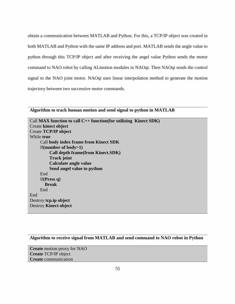
Algorithm to track human motion and send signal to python in MATLAB
Call MAX function to call C++ function(for utilizing Kinect SDK)
Create kinect object
Create TCP/IP object
While true
Call body index frame from Kinect SDK
If(number of body>1)
Call depth frame(from Kinect.SDK)
Track joint
Calculate angle value
Send angel value to python
End
If(Press q)
Break
End
End
Destroy tcp.ip object
Destroy Kinect object
Algorithm to receive signal from MATLAB and send command to NAO robot in Python
Create motion proxy for NAO
Create TCP/IP object
Create communication
56
If connection = true
While true
Receive angle data
If data=true
Call motion proxy
Send motor command
If data = false
Break
Destroy connection
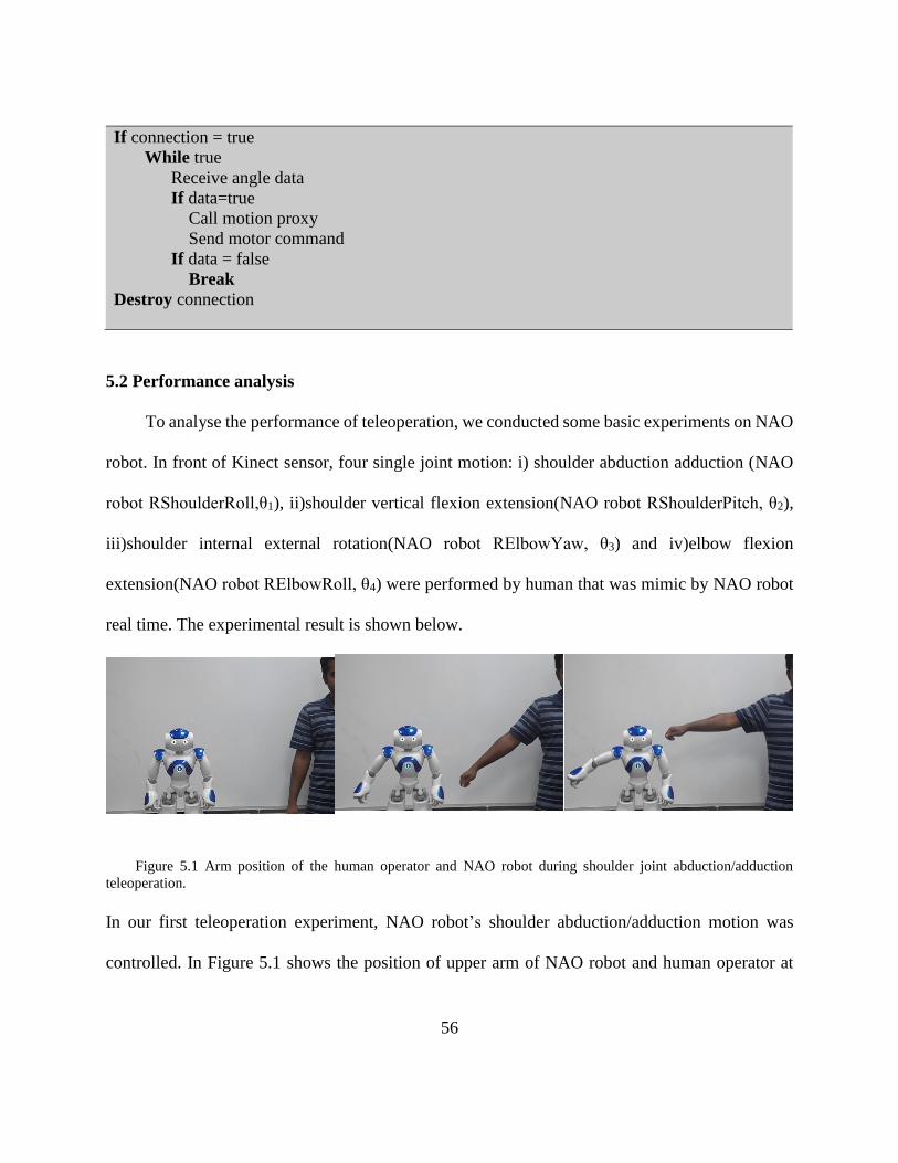
5.2 Performance analysis
To analyse the performance of teleoperation, we conducted some basic experiments on NAO
robot. In front of Kinect sensor, four single joint motion: i) shoulder abduction adduction (NAO
robot RShoulderRoll,θ1), ii)shoulder vertical flexion extension(NAO robot RShoulderPitch, θ2),
iii)shoulder internal external rotation(NAO robot RElbowYaw, θ3) and iv)elbow flexion
extension(NAO robot RElbowRoll, θ4) were performed by human that was mimic by NAO robot
real time. The experimental result is shown below.
Figure 5.1 Arm position of the human operator and NAO robot during shoulder joint abduction/adduction
teleoperation.
In our first teleoperation experiment, NAO robot’s shoulder abduction/adduction motion was
controlled. In Figure 5.1 shows the position of upper arm of NAO robot and human operator at
57
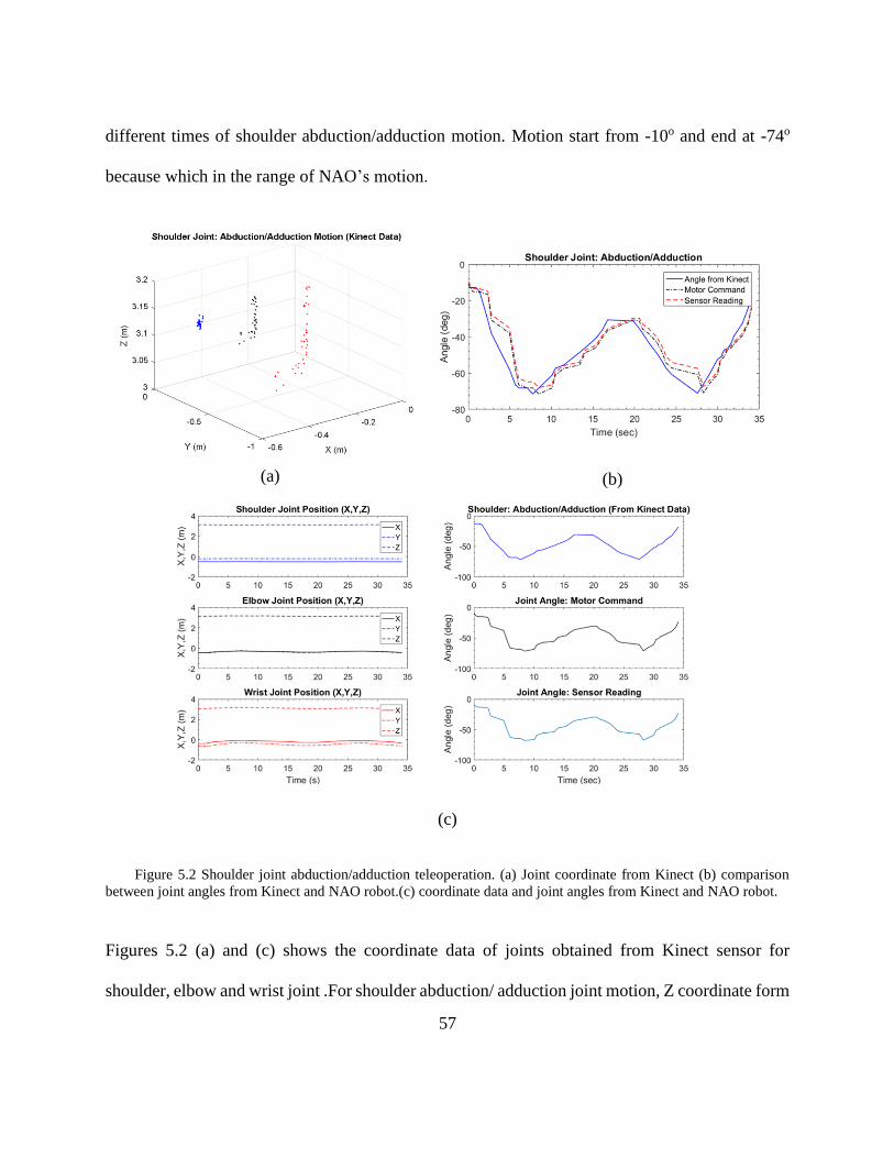
different times of shoulder abduction/adduction motion. Motion start from -10o and end at -74o
because which in the range of NAO’s motion.
(a)
(b)
(c)
Figure 5.2 Shoulder joint abduction/adduction teleoperation. (a) Joint coordinate from Kinect (b) comparison
between joint angles from Kinect and NAO robot.(c) coordinate data and joint angles from Kinect and NAO robot.
Figures 5.2 (a) and (c) shows the coordinate data of joints obtained from Kinect sensor for
shoulder, elbow and wrist joint .For shoulder abduction/ adduction joint motion, Z coordinate form
58
Kinect frame for all joint should be constant which is match with the tracked result. Figures 5.2
(b) and (c) display the trajectory followed by human operator and NAO robot. We obtained the
motor position feedback from NAO robot through Device Communication Manager (DCM). There
are to separate reading comes from NAO robot DCM one reading that comes from motor controller
output that goes to the motor for execution which is called motor command and other reading
comes from the Joint position sensor MRE (Magnetic Rotary Encoders) which is called sensor
reading. From the (b) it is clearly seen that there are some difference between this two reading.
This is because when NAO robot move any joint the motion is interpolated between current value
of motor position and the targeted value and it takes some time for the command to go to the motor
cards and take some time for sending the reading back. There is also some laggings between Kinect
value and motor command because these two programs are in two different platform Kinect extract
data in MATLAB and Python communicate with NAO robot through wifi communication.
MATLAB and Python communicate through tcp/ip communication. There is some delay between
sending and receiving data between MATLAB and Python. In addition, NAO robot need some
time to execute all its current command to take next command. To eliminate this all the platforms
are needed to be synchronized. However, it is a little bit difficult when there more than three
platforms being used (in this case MATLAB, Python, NAOqi). Nevertheless, from figures it is
clear that the pattern of joint trajectory followed by NAO robot is exactly similar to the operator
trajectory pattern.
59
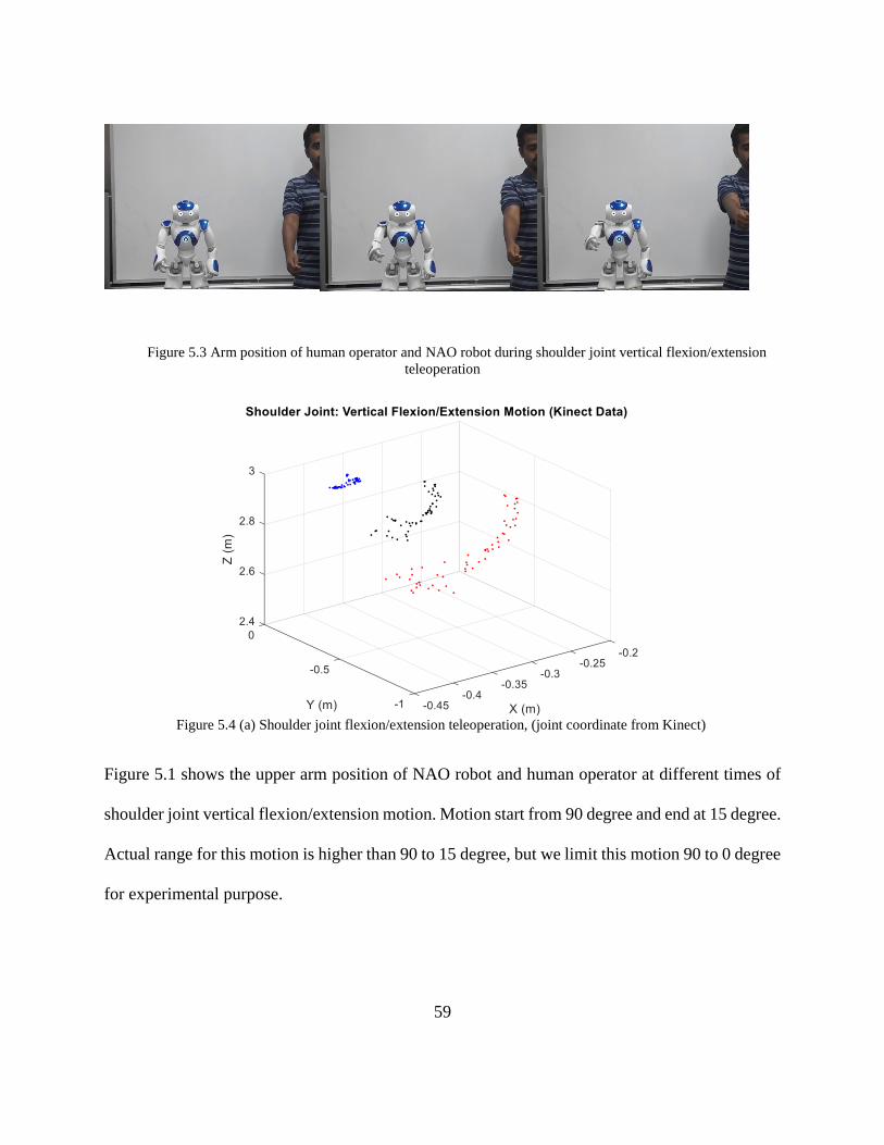
Figure 5.3 Arm position of human operator and NAO robot during shoulder joint vertical flexion/extension
teleoperation
Figure 5.4 (a) Shoulder joint flexion/extension teleoperation, (joint coordinate from Kinect)
Figure 5.1 shows the upper arm position of NAO robot and human operator at different times of
shoulder joint vertical flexion/extension motion. Motion start from 90 degree and end at 15 degree.
Actual range for this motion is higher than 90 to 15 degree, but we limit this motion 90 to 0 degree
for experimental purpose.
60
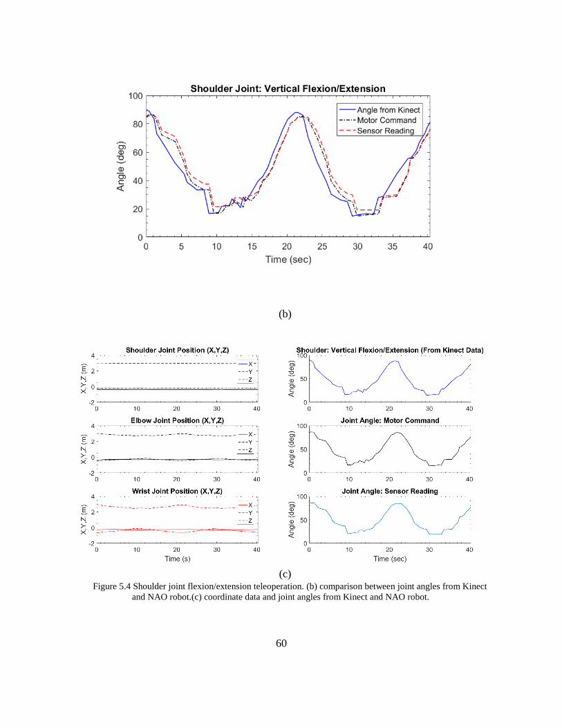
(b)
(c)
Figure 5.4 Shoulder joint flexion/extension teleoperation. (b) comparison between joint angles from Kinect
and NAO robot.(c) coordinate data and joint angles from Kinect and NAO robot.
61
Figure 5.5 (a) and (c) shows the coordinate data obtained from Kinect sensor for shoulder, elbow
and wrist joint .For shoulder vertical flexion/extension joint motion X coordinate form Kinect
frame for all joint should be constant which is match with the tracked result. Figure 5.5 (b) and (c)
display the trajectory followed by human operator and NAO robot.
Figure 5.5 Arm position of human operator and NAO robot during shoulder joint
Internal/external rotation during teleoperation
(a)
62
(b)
(c)
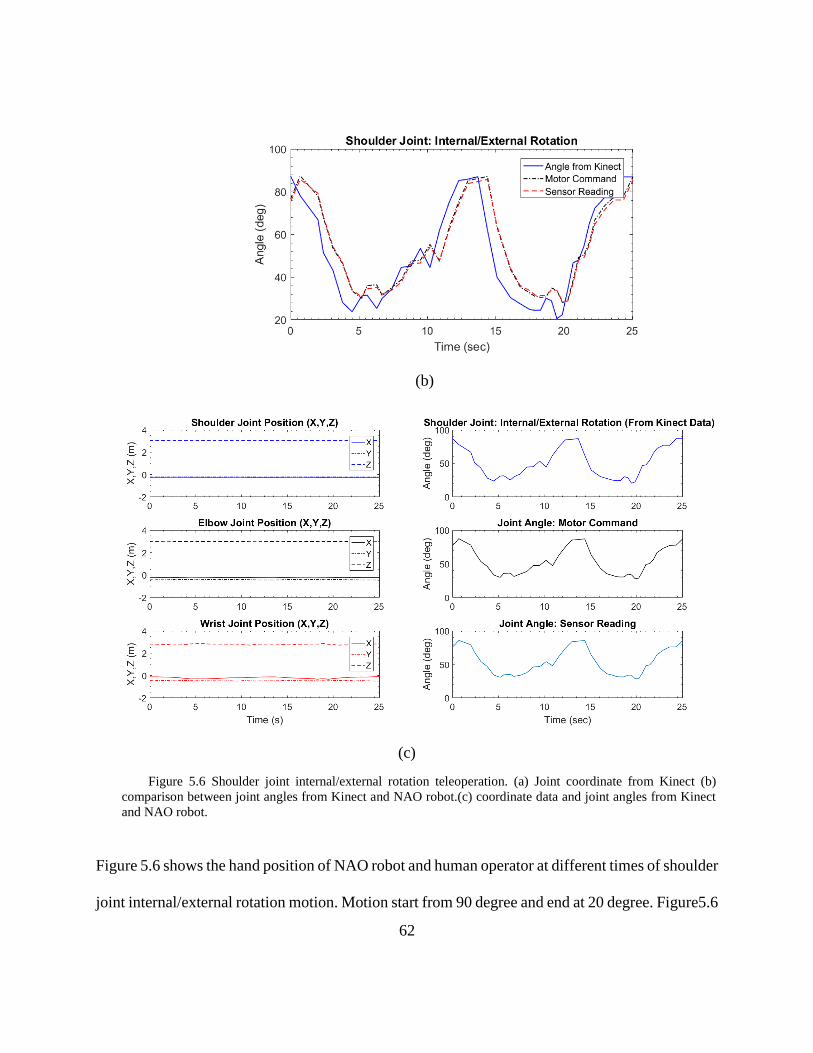
Figure 5.6 shows the hand position of NAO robot and human operator at different times of shoulder
joint internal/external rotation motion. Motion start from 90 degree and end at 20 degree. Figure5.6
Figure 5.6 Shoulder joint internal/external rotation teleoperation. (a) Joint coordinate from Kinect (b)
comparison between joint angles from Kinect and NAO robot.(c) coordinate data and joint angles from Kinect
and NAO robot.
63
(a) and (c) shows the coordinate data obtained from Kinect sensor for shoulder, elbow and wrist
joint .For shoulder internal/external rotation joint motion coordinates for elbow and shoulder joint
form Kinect frame should be similar for all position because only wrist joint is moving here. In the
Figure 5.6 (a) it is seen that all the blue and black points are clustered in same position throughout
the time. Figure 5.6 (b) and (c) display the trajectory followed by human operator and NAO robot.
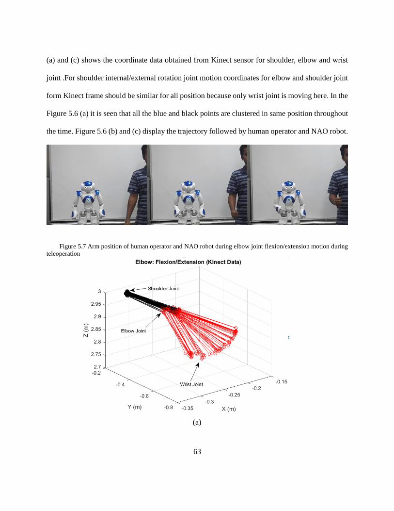
Figure 5.7 Arm position of human operator and NAO robot during elbow joint flexion/extension motion during
teleoperation
(a)
64
(b)
(c)
65
(d)
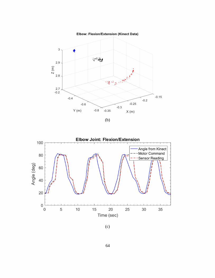
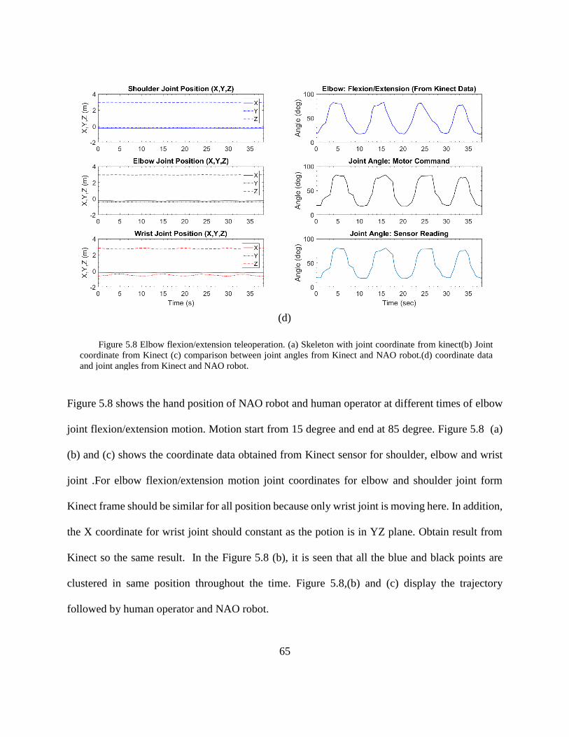
Figure 5.8 shows the hand position of NAO robot and human operator at different times of elbow
joint flexion/extension motion. Motion start from 15 degree and end at 85 degree. Figure 5.8 (a)
(b) and (c) shows the coordinate data obtained from Kinect sensor for shoulder, elbow and wrist
joint .For elbow flexion/extension motion joint coordinates for elbow and shoulder joint form
Kinect frame should be similar for all position because only wrist joint is moving here. In addition,
the X coordinate for wrist joint should constant as the potion is in YZ plane. Obtain result from
Kinect so the same result. In the Figure 5.8 (b), it is seen that all the blue and black points are
clustered in same position throughout the time. Figure 5.8,(b) and (c) display the trajectory
followed by human operator and NAO robot.
Figure 5.8 Elbow flexion/extension teleoperation. (a) Skeleton with joint coordinate from kinect(b) Joint
coordinate from Kinect (c) comparison between joint angles from Kinect and NAO robot.(d) coordinate data
and joint angles from Kinect and NAO robot.
66
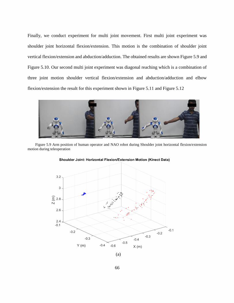
Finally, we conduct experiment for multi joint movement. First multi joint experiment was
shoulder joint horizontal flexion/extension. This motion is the combination of shoulder joint
vertical flexion/extension and abduction/adduction. The obtained results are shown Figure 5.9 and
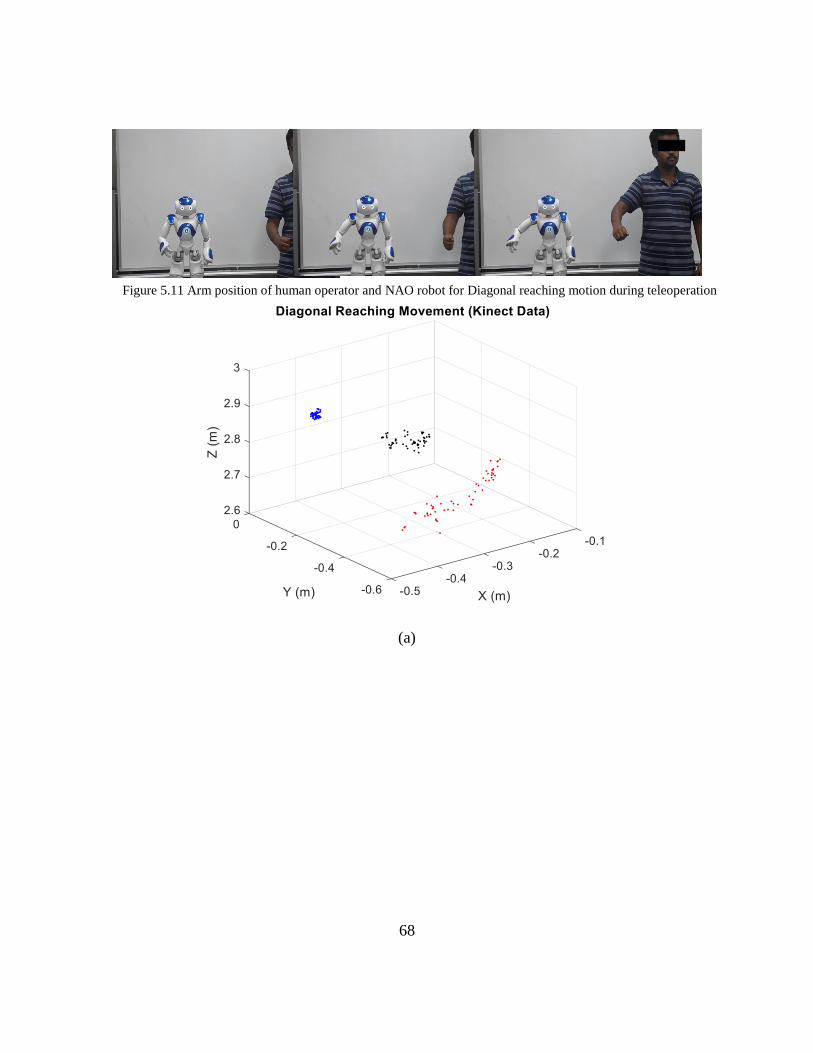
Figure 5.10. Our second multi joint experiment was diagonal reaching which is a combination of
three joint motion shoulder vertical flexion/extension and abduction/adduction and elbow
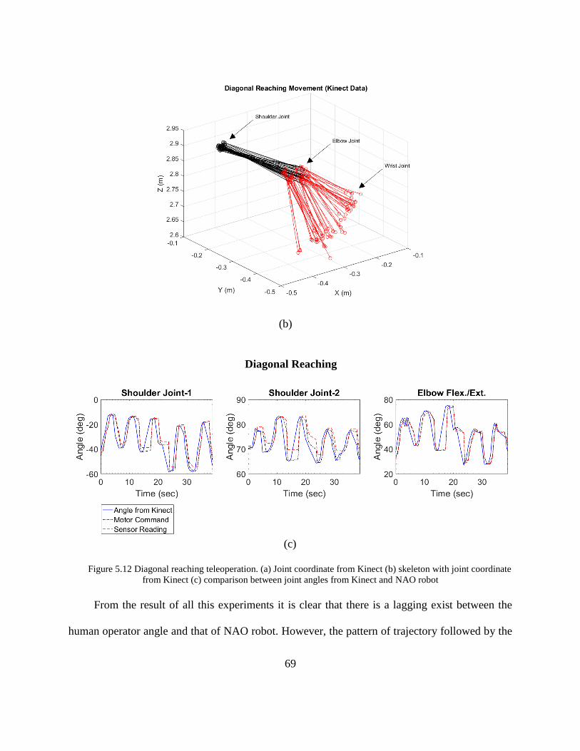
flexion/extension the result for this experiment shown in Figure 5.11 and Figure 5.12
Figure 5.9 Arm position of human operator and NAO robot during Shoulder joint horizontal flexion/extension
motion during teleoperation
(a)
67
(b)
(c)
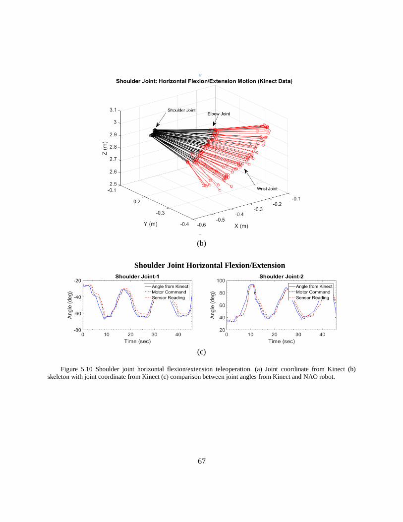
Figure 5.10 Shoulder joint horizontal flexion/extension teleoperation. (a) Joint coordinate from Kinect (b)
skeleton with joint coordinate from Kinect (c) comparison between joint angles from Kinect and NAO robot.
Shoulder Joint Horizontal Flexion/Extension
68
Figure 5.11 Arm position of human operator and NAO robot for Diagonal reaching motion during teleoperation
(a)
69
(b)
(c)
Figure 5.12 Diagonal reaching teleoperation. (a) Joint coordinate from Kinect (b) skeleton with joint coordinate
from Kinect (c) comparison between joint angles from Kinect and NAO robot
From the result of all this experiments it is clear that there is a lagging exist between the
human operator angle and that of NAO robot. However, the pattern of trajectory followed by the
Diagonal Reaching

70
NAO robot was exactly same that of the human operator. The main objective of teleoperation is to
follow the motion trajectory produced by the human operator. Which is fulfilled in our case. By
this method, one can easily control NAO robot joint angle remotely as long as they are connected
to same network. It will be useful to introduce new exercise remotely.
71
CHAPTER 6
NAO GUIDED SUPERVISED REHABILITATION
This chapter focuses on Aim-3. To develop a supervision or an observation system of
rehabilitation exercise using Kinect and humanoid robot NAO. In Aim-1, a set of rehabilitation
exercises library have been built for NAO robot to demonstrate and instruct subject during
rehabilitation. These are limited to instruction level only. There is no room for supervision or
taking feedback from subject. Furthermore, in Aim-2 described in the previous chapter,
teleoperation for remote rehabilitation has been introduced and that could introduce any new
exercise remotely as well. Neither Aim-1 nor Aim-2 can be supervised by NAO robot. However,
the ongoing chapter describes a system that uses Kinect to observe the exercise performed by
subject in front of it has been developed. Based on this observation NAO provides feedback to the
subject about his/her performance. First, we describe about supervision system then discuss about
the experimental result in rest of this chapter.
6.1 Supervision system using NAO and Kinect
In this study, we only focused on the visual supervisions for the performed exercise in front
of NAO robot. Here visual supervision means supervised all those facts that can be easily detected
by normal vision. We considered following key points to be supervised:
• Accuracy of performed exercise
• Time required to perform the exercise
• Range of motion for a particular exercise.
72
First, the accuracy means the right way to perform a particular exercise. For instance, only
shoulder joint θ2 will vary when subject is asked to do shoulder vertical flexion/extension exercise
in ideal case while not all other joints should be moving. If any other joints rotate, we term this not
the right way to perform shoulder vertical flexion/extension exercise. Second, time required is
quantified by the amount of time be taken by the subject to complete given exercise. With the
feedback based on time being either okay, too fast, or too slow. Third, range of motion means the
maximum angle covered during the given exercise.
To develop this supervision system we used Kinect sensor for smart vision and analyze the
motion of the performed exercise. The Kinect acts as vision system for NAO robot and send the
analyzed result to NAO robot that provides the feedback of how subject performed exercise
eventually.
Supervision system is more like cooperative exercise described in chapter 5. The only
difference is that in this case NAO examines the performed exercise through Kinect and provides
feedback.
6.2 Performance analysis
We conducted individual joint motion exercise of three joint (shoulder abduction/adduction,
shoulder vertical flexion/extension and elbow flexion extension/extension) and one multi joint
motion exercise (diagonal reaching movement) to determine performance of the supervision
system. In ideal case for a single joint motion, only that joint angle can vary and other are not
supposed to move. However, human arm movements do not follow the ideal case and they are
highly variable (Sanger 2000, Sarlegna and Sainburg 2007). That is why, for single joint
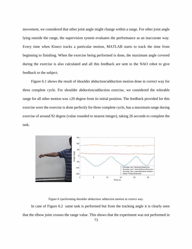
73
movement, we considered that other joint angle might change within a range. For other joint angle
lying outside the range, the supervision system evaluates the performance as an inaccurate way.
Every time when Kinect tracks a particular motion, MATLAB starts to track the time from
beginning to finishing. When the exercise being performed is done, the maximum angle covered
during the exercise is also calculated and all this feedback are sent to the NAO robot to give
feedback to the subject.
Figure 6.1 shows the result of shoulder abduction/adduction motion done in correct way for
three complete cycle. For shoulder abduction/adduction exercise, we considered the tolerable
range for all other motion was ±20 degree from its initial position. The feedback provided for this
exercise were the exercise is done perfectly for three complete cycle, has a maximum range during
exercise of around 92 degree (value rounded to nearest integer), taking 26 seconds to complete the
task.
Figure 6.1performing shoulder abduction/ adduction motion in correct way.
In case of Figure 6.2 same task is performed but from the tracking angle it is clearly seen
that the elbow joint crosses the range value. This shows that the experiment was not performed in
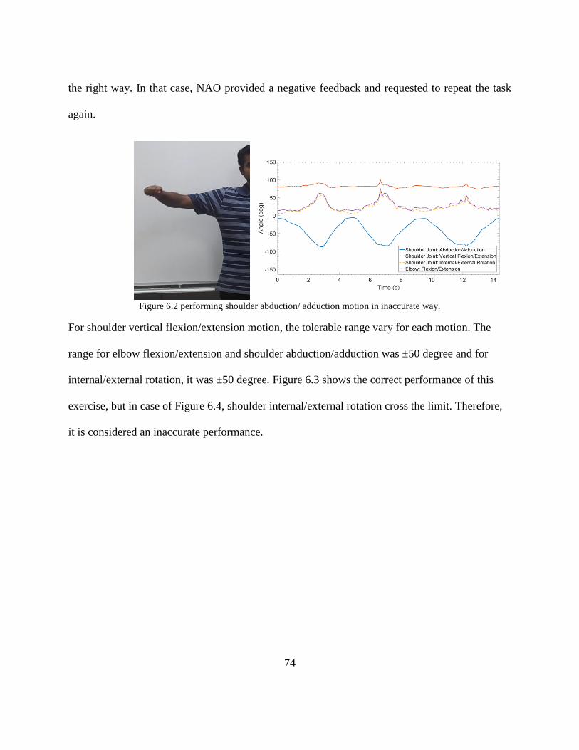
74
the right way. In that case, NAO provided a negative feedback and requested to repeat the task
again.
Figure 6.2 performing shoulder abduction/ adduction motion in inaccurate way.
For shoulder vertical flexion/extension motion, the tolerable range vary for each motion. The
range for elbow flexion/extension and shoulder abduction/adduction was ±50 degree and for
internal/external rotation, it was ±50 degree. Figure 6.3 shows the correct performance of this
exercise, but in case of Figure 6.4, shoulder internal/external rotation cross the limit. Therefore,
it is considered an inaccurate performance.
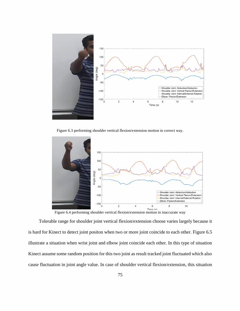
75
Figure 6.3 performing shoulder vertical flexion/extension motion in correct way.
Figure 6.4 performing shoulder vertical flexion/extension motion in inaccurate way
Tolerable range for shoulder joint vertical flexion/extension choose varies largely because it
is hard for Kinect to detect joint positon when two or more joint coincide to each other. Figure 6.5
illustrate a situation when wrist joint and elbow joint coincide each other. In this type of situation
Kinect assume some random position for this two joint as result tracked joint fluctuated which also
cause fluctuation in joint angle value. In case of shoulder vertical flexion/extension, this situation
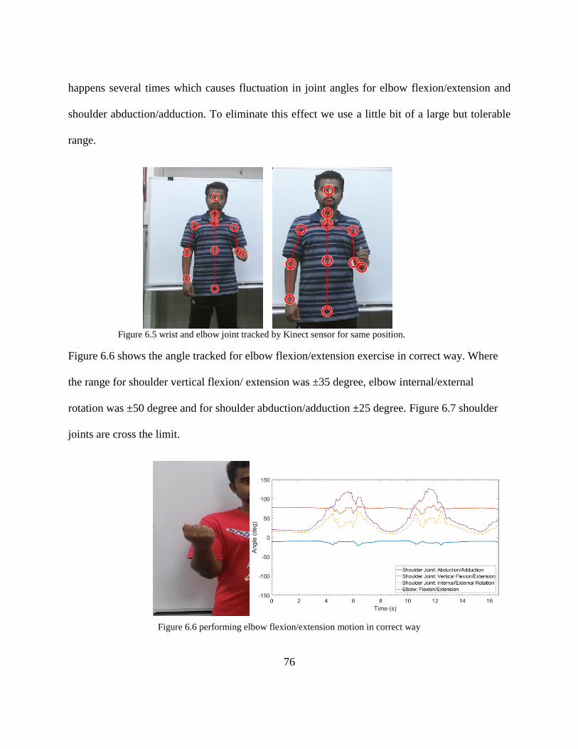
76
happens several times which causes fluctuation in joint angles for elbow flexion/extension and
shoulder abduction/adduction. To eliminate this effect we use a little bit of a large but tolerable
range.
Figure 6.5 wrist and elbow joint tracked by Kinect sensor for same position.
Figure 6.6 shows the angle tracked for elbow flexion/extension exercise in correct way. Where
the range for shoulder vertical flexion/ extension was ±35 degree, elbow internal/external
rotation was ±50 degree and for shoulder abduction/adduction ±25 degree. Figure 6.7 shoulder
joints are cross the limit.
Figure 6.6 performing elbow flexion/extension motion in correct way
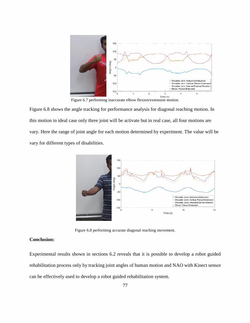
77
Figure 6.7 performing inaccurate elbow flexion/extension motion.
Figure 6.8 shows the angle tracking for performance analysis for diagonal reaching motion. In
this motion in ideal case only three joint will be activate but in real case, all four motions are
vary. Here the range of joint angle for each motion determined by experiment. The value will be
vary for different types of disabilities.
Figure 6.8 performing accurate diagonal reaching movement.
Conclusion:
Experimental results shown in sections 6.2 reveals that it is possible to develop a robot guided
rehabilitation process only by tracking joint angles of human motion and NAO with Kinect sensor
can be effectively used to develop a robot guided rehabilitation system.
78
CHAPTER 7
CONCLUSION AND FUTURE WORKS
8.1 Conclusion
A robot guided rehabilitation scheme was developed using a humanoid robot NAO and a
Kinect sensor to provide grounds for effective rehabilitation of people with disabilities at the
level of shoulder and elbow joint movements.
To demonstrate rehabilitation exercises with NAO, a library of recommended rehabilitation
exercises involving shoulder and elbow joint movements was formed in Choregraphe (graphical
programming interface). In experiments, NAO was maneuvered to instruct and demonstrate the
exercises from the NRL. A complex ‘touch and play’ game was also developed where NAO
plays with the subject that represents a multi-joint movements exercise.
To develop the proposed tele-rehabilitation scheme, kinematic model of human upper-extremity
was developed based on modified Denavit-Hartenberg notations. A complete geometric solution
was developed to find a unique inverse kinematic solution of human upper-extremity from the
data obtained by Kinect. Experiments’ results reveals that NAO can be tele-operated to instruct
and demonstrate subjects to perform different arm movement exercises.
An intelligent control algorithm was developed in MATLAB for the proposed NAO guided
supervised rehabilitation scheme. Experimental results show that NAO and Kinect sensor can
effectively use to supervise and guide the subjects in performing active rehabilitation exercises
for shoulder and elbow joint movements.
79
8.2 Future Works
To provide robot assisted rehabilitation future projects may include developing an
intelligent robot sensor system that can assist therapist to instruct, supervise and demonstrate
exercise intelligently. Future studies/works can also be expanded as follows:
• Developing a more reliable, cheap and noise free motion-tracking system because data
form Kinect contains some noise.
• Developing a low cost humanoid robot with more processing power and high durability.
NAO has limitations in his processing power.
• Develop a robot with more degree of freedom in its hand to cover all exercise for human
upper limb rehabilitation exercise
• Introduce artificial intelligence in NAO to make it more cooperative in case of decision
making.
• Introduce adaptive learning technology to NAO
• Develop a cloud server system of rehabilitation exercises in which individuals can access
from anywhere to explore different types of rehabilitation exercises.
Finally, it is recommended to develop a rehabilitation protocol for robot-based rehabilitation
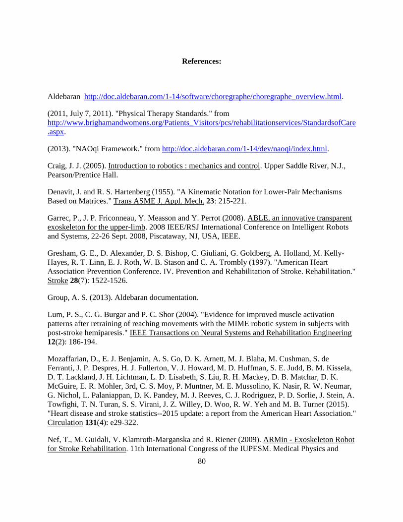
80
References:
Aldebaran http://doc.aldebaran.com/1-14/software/choregraphe/choregraphe_overview.html.
(2011, July 7, 2011). "Physical Therapy Standards." from
http://www.brighamandwomens.org/Patients_Visitors/pcs/rehabilitationservices/StandardsofCare
.aspx.
(2013). "NAOqi Framework." from http://doc.aldebaran.com/1-14/dev/naoqi/index.html.
Craig, J. J. (2005). Introduction to robotics : mechanics and control. Upper Saddle River, N.J.,
Pearson/Prentice Hall.
Denavit, J. and R. S. Hartenberg (1955). "A Kinematic Notation for Lower-Pair Mechanisms
Based on Matrices." Trans ASME J. Appl. Mech. 23: 215-221.
Garrec, P., J. P. Friconneau, Y. Measson and Y. Perrot (2008). ABLE, an innovative transparent
exoskeleton for the upper-limb. 2008 IEEE/RSJ International Conference on Intelligent Robots
and Systems, 22-26 Sept. 2008, Piscataway, NJ, USA, IEEE.
Gresham, G. E., D. Alexander, D. S. Bishop, C. Giuliani, G. Goldberg, A. Holland, M. Kelly-
Hayes, R. T. Linn, E. J. Roth, W. B. Stason and C. A. Trombly (1997). "American Heart
Association Prevention Conference. IV. Prevention and Rehabilitation of Stroke. Rehabilitation."
Stroke 28(7): 1522-1526.
Group, A. S. (2013). Aldebaran documentation.
Lum, P. S., C. G. Burgar and P. C. Shor (2004). "Evidence for improved muscle activation
patterns after retraining of reaching movements with the MIME robotic system in subjects with
post-stroke hemiparesis." IEEE Transactions on Neural Systems and Rehabilitation Engineering
12(2): 186-194.
Mozaffarian, D., E. J. Benjamin, A. S. Go, D. K. Arnett, M. J. Blaha, M. Cushman, S. de
Ferranti, J. P. Despres, H. J. Fullerton, V. J. Howard, M. D. Huffman, S. E. Judd, B. M. Kissela,
D. T. Lackland, J. H. Lichtman, L. D. Lisabeth, S. Liu, R. H. Mackey, D. B. Matchar, D. K.
McGuire, E. R. Mohler, 3rd, C. S. Moy, P. Muntner, M. E. Mussolino, K. Nasir, R. W. Neumar,
G. Nichol, L. Palaniappan, D. K. Pandey, M. J. Reeves, C. J. Rodriguez, P. D. Sorlie, J. Stein, A.
Towfighi, T. N. Turan, S. S. Virani, J. Z. Willey, D. Woo, R. W. Yeh and M. B. Turner (2015).
"Heart disease and stroke statistics--2015 update: a report from the American Heart Association."
Circulation 131(4): e29-322.
Nef, T., M. Guidali, V. Klamroth-Marganska and R. Riener (2009). ARMin - Exoskeleton Robot
for Stroke Rehabilitation. 11th International Congress of the IUPESM. Medical Physics and
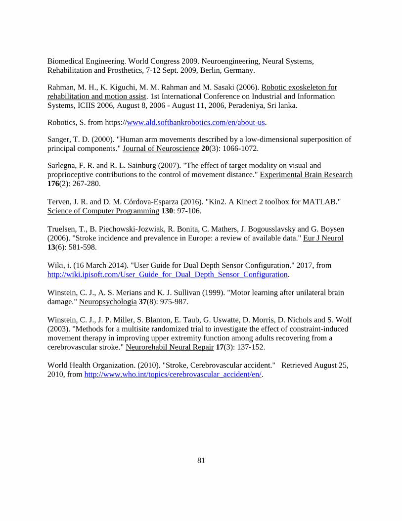
81
Biomedical Engineering. World Congress 2009. Neuroengineering, Neural Systems,
Rehabilitation and Prosthetics, 7-12 Sept. 2009, Berlin, Germany.
Rahman, M. H., K. Kiguchi, M. M. Rahman and M. Sasaki (2006). Robotic exoskeleton for
rehabilitation and motion assist. 1st International Conference on Industrial and Information
Systems, ICIIS 2006, August 8, 2006 - August 11, 2006, Peradeniya, Sri lanka.
Robotics, S. from https://www.ald.softbankrobotics.com/en/about-us.
Sanger, T. D. (2000). "Human arm movements described by a low-dimensional superposition of
principal components." Journal of Neuroscience 20(3): 1066-1072.
Sarlegna, F. R. and R. L. Sainburg (2007). "The effect of target modality on visual and
proprioceptive contributions to the control of movement distance." Experimental Brain Research
176(2): 267-280.
Terven, J. R. and D. M. Córdova-Esparza (2016). "Kin2. A Kinect 2 toolbox for MATLAB."
Science of Computer Programming 130: 97-106.
Truelsen, T., B. Piechowski-Jozwiak, R. Bonita, C. Mathers, J. Bogousslavsky and G. Boysen
(2006). "Stroke incidence and prevalence in Europe: a review of available data." Eur J Neurol
13(6): 581-598.
Wiki, i. (16 March 2014). "User Guide for Dual Depth Sensor Configuration." 2017, from
http://wiki.ipisoft.com/User_Guide_for_Dual_Depth_Sensor_Configuration.
Winstein, C. J., A. S. Merians and K. J. Sullivan (1999). "Motor learning after unilateral brain
damage." Neuropsychologia 37(8): 975-987.
Winstein, C. J., J. P. Miller, S. Blanton, E. Taub, G. Uswatte, D. Morris, D. Nichols and S. Wolf
(2003). "Methods for a multisite randomized trial to investigate the effect of constraint-induced
movement therapy in improving upper extremity function among adults recovering from a
cerebrovascular stroke." Neurorehabil Neural Repair 17(3): 137-152.
World Health Organization. (2010). "Stroke, Cerebrovascular accident." Retrieved August 25,
2010, from http://www.who.int/topics/cerebrovascular_accident/en/.