Embed Size (px)
Citation preview
A visually guided swimming robotGregory Dudek‡‡, Michael Jenkin**, Chris Prahacs*, Andrew Hogue**, Junaed Sattar‡‡,
Philippe Giguere‡‡, Andrew German**, Hui Liu‡, Shane Saunderson*,Arlene Ripsman**, Saul Simhon‡‡, Luz-Abril Torres‡‡, Evangelos Milios‡, Pifu Zhang‡, Ioannis Rekletis‡‡
‡‡School of ComputerScience
McGill University3480 University St.
Montreal, PQ, Canada
**Computer Science andEngineering
York University4700 Keele St.
Toronto, Ontario, Canada
* Mechanical EngineeringMcGill University3480 University St.
Montreal, PQ, Canada
‡Faculty of ComputerScience
Dalhousie University6050 University Ave.
Dalhousie, NS, Canada
Abstract – We describe recent results obtained with AQUA, amobile robot capable of swimming, walking and amphibiousoperation. Designed to rely primarily on visual sensors, theAQUA robot uses vision to navigate underwater using servo-based guidance, and also to obtain high-resolution range scans ofits local environment. This paper describes some of thepragmatic and logistic obstacles encountered, and provides anoverview of some of the basic capabilities of the vehicle and itsassociated sensors. Moreover, this paper presents the first everamphibious transition from walking to swimming.
Keywords-autonomous robot, aquatic robot, robotic sensing
I. INTRODUCTION
The aquatic environment presents an almost ideal test-bedfor the evaluation and development of robotic technologies.The environment is highly dynamic and three dimensional.Vehicles operating in this realm must cope with unpredictable3D motion of the vehicle itself complicating any task to beperformed. Extremely limited off-board communicationunderwater requires that robots must operate fullyautonomously or under operator control through a tether.Many surveillance and data collection tasks require that avehicle be positioned in the same location for a period of time.Surge and underwater currents prevent this from happening,thus robust and accurate pose maintenance is a requirement foraquatic vehicles. Also, standard mapping techniquesoriginally developed for indoor robot navigation are notgeneral enough to describe the inherently six degree offreedom aquatic environment. A natural choice for sensing isto use cameras and computer vision techniques to aid innavigation and trajectory reconstruction. However, a host ofother problems plague underwater computer vision techniques.For example, the turbidity of the water caused by floatingsedimentation (‘aquatic snow’) and other floating debriswreaks havoc on standard techniques for visual understandingof the world. The environment itself provides uniquechallenges for the mechanical design of vehicles – keeping thewater away from electrical equipment is essential and rarelyrequired for navigating university laboratory hallways.
Given the complexity of the aquatic domain, and thedesirability of autonomous and semi-autonomous systems toaid in its exploration, there has been a long history of
development of aquatic robots (cf. [2]) and their sensors (cf.[15]). The vast majority of aquatic vehicles are controlled bythrusters and control surfaces. Many are designed to besupported by a sizeable shore- or ship-mounted infrastructureto provide external power, communication and tether due totheir large size.
In contrast to many of these earlier aquatic vehicles, withinthe AQUA project we are developing a small-scale leggedswimming robot whose core sensing modality is image-based;such a robot is small, portable and maneuverable. The specifictarget application we are working towards is theenvironmental assessment and longitudinal analysis of coralreef environments. These environments are difficult tonavigate with traditional autonomous underwater vehicles orROVs (remotely operated vehicles) due to the shallow depthsand the significant presence of marine life. A major drawbackfor traditional vehicles is the usage of thrusters at shallowdepths which stirs up much of the ocean floor reducingvisibility and endangering the coral and marine life.
Reefs are ecologically important environments that areseriously threatened yet a clear objective assessment of theirhealth is a serious challenge to which automated methods mayprove valuable. In particular, coral reefs occupy only 0.7% ofthe ocean floor, but provide homes and vital nursery groundsfor 25% of all marine species on the planet. Furthermore, reefmonitoring serves as a valuable template for a range of othersignificant applications. A well established bio-assessmentmethodology is to either repeatedly visit a set of selectedlocations or to regularly swim over a particular trajectory andvisually inspect the marine flora and fauna. This specific taskis labor intensive for human operators and, as a sampleapplication, it may be well suited to the AQUA vehicle.
This paper provides some details of the design and controlof the AQUA vehicle and of one of its primary visualcomponents, a combined inertial-trinocular camera module.Further details of the vehicle, and in particular details of anacoustic localization system for the robot can be found in [4].
II. THE AQUA PLATFORM
The AQUA vehicle represents a novel approach to aquaticvehicle design. Rather than relying on thrusters and controlsurfaces, the AQUA vehicle relies on legged locomotion. The
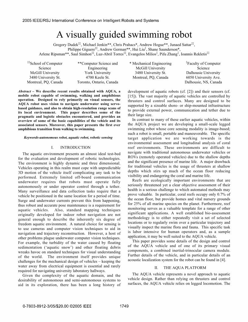
vehicle uses its six actuators, coupled to specially designedlegs and/or fins, to move either as a walking vehicle or as alegged swimmer. Legs provide the vehicle with a variety ofdifferent locomotive strategies including the ability to walk onsolid surfaces, and to swim on the surface of the water or inthe open ocean. Walking behaviors are based on variations ofa rotary gait (Figure 1(a)), while swimming behaviors dependon variations of an oscillating leg motion (Figure 1(b)).
AQUA is based on RHex, a terrestrial six-legged robotdeveloped in part by the Ambulatory Robotics Lab at McGillin collaboration with the University of Michigan, theUniversity of California at Berkeley and Carnegie MellonUniversity [1]. AQUA’s required capabilities include surfaceand underwater swimming, diving to a depth of 15m, stationkeeping and crawling at the bottom of the sea. For propulsion,the vehicle deviates from traditional ROV through the use ofsix paddles, which also act as control surfaces duringswimming, and as legs when walking. The paddleconfiguration gives the robot direct control over five of the sixdegrees of freedom: surge, heave, pitch, roll and yaw. Aninclinometer and a compass onboard are used to assist in thecontrol of the robot’s motion underwater.
The robot is approximately 65 cm long, 50 cm wide (at thefins), and 13cm high. It is encased within an aluminumwaterproof shell and displaces about 18 kg of water. The robotis powered by two onboard NiMH batteries providing overtwo hours of continuous operation. Onboard computation isperformed using PC/104 computers, one running a real-timeoperating system (QNX), and the other an embedded versionof Linux. Camera, sensor and control signals are sent to afloating platform at the surface via fiber-optic tether. Thisinformation is used by the operator to control the robot viausage of a gamepad controlled command interface.
Each of AQUA’s six legs is individually controlled by asingle axis motor. The onboard computer provides real-timecontrol of the set of six limbs. Although a number of differentleg designs have been developed and tested on the vehicle, acommon design feature of the legs is that they are compliant.
The spring energy stored in the legs as they bend under load isan integral part of the vehicle’s locomotion strategy.
AQUA’s unique locomotion strategy provides greatflexibility in terms of potential modes of locomotion. Figure 1shows the AQUA vehicle moving in three very differentmodes. In Figure 1(a), the AQUA vehicle is shown with itsamphibious legs walking along the beach near the surf zone.During walking locomotion, the AQUA vehicle uses its sixsingle-jointed limbs to walk using an alternating gait basedupon a gait originally designed for the Rugged RHEXplatform. When the vehicle moves through the surf zone, ittransits to a surface swimming gait (see Figure 1(b)). Here theamphibious legs are used to provide thrust along the surface ofthe water. Finally, when the water depth is sufficient, thevehicle can transit to an open water swimming mode in whichthe vehicle ``swims’’ in the full 6DOF space that exists in theopen ocean. Figure 1 also illustrates that the AQUA vehiclecan be deployed with different sets of legs. Individual legs aredesigned to be easily attached and removed from the vehicle,and the design of a robust set of ‘all weather’ legs is the topicof ongoing research.
Limbed locomotion requires the development ofappropriate gaits to drive the legs in a coordinated manner inorder to move the vehicle. A set of gaits have been developedthat provide controlled motion of the vehicle when walking,swimming on the surface and swimming in open water.
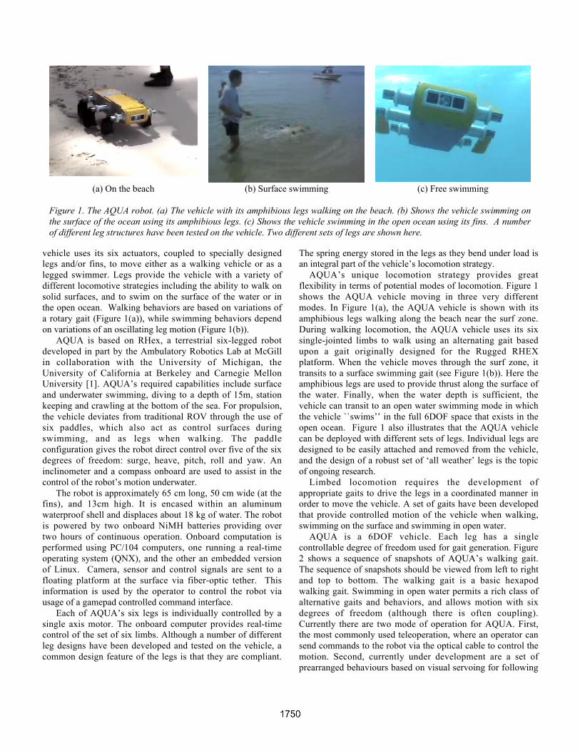
AQUA is a 6DOF vehicle. Each leg has a singlecontrollable degree of freedom used for gait generation. Figure2 shows a sequence of snapshots of AQUA’s walking gait.The sequence of snapshots should be viewed from left to rightand top to bottom. The walking gait is a basic hexapodwalking gait. Swimming in open water permits a rich class ofalternative gaits and behaviors, and allows motion with sixdegrees of freedom (although there is often coupling).Currently there are two mode of operation for AQUA. First,the most commonly used teleoperation, where an operator cansend commands to the robot via the optical cable to control themotion. Second, currently under development are a set ofprearranged behaviours based on visual servoing for following
(a) On the beach (b) Surface swimming (c) Free swimming
Figure 1. The AQUA robot. (a) The vehicle with its amphibious legs walking on the beach. (b) Shows the vehicle swimming onthe surface of the ocean using its amphibious legs. (c) Shows the vehicle swimming in the open ocean using its fins. A numberof different leg structures have been tested on the vehicle. Two different sets of legs are shown here.
a visual target and also for following a set trajectory, Inparticular, by application of the appropriate gait the robot isable to roll, pitch, yaw, surge, and heave. At present thesebehaviors have been tested under manual control and the robotappears rather easy to control manually. Complex 6DOFtrajectories can be challenging to track, and this is one of thefactors motivating the use of servo-controlled gaits, even formanual vehicle guidance.
III. SENSING WITH AQUA
The AQUA robot enclosure contains both forward- andrear-facing video cameras. These sensors are used primarilyfor vehicle teleoperation and visual servoing tasks. Othersensors (e.g. the acoustic localization sensor and the trinocularsensor) are currently being evaluated in external housings andwill be integrated into the body of the robot in later versions ofthe vehicle. The acoustic localization sensor is described insome detail elsewhere ([4]). Here we provide some details onthe trinocular vision sensor system, color correctionprocessesing and video servoing.
The AQUA platform is intended for use as a device to aid inenvironmental assessment, and in particular to aid in theassessment of reef damage and rehabilitation. Thus two keyinspection tasks are the collection of video footage, and theconstruction of 3D surface and volumetric models of the reefstructure off-line. Later, off-line comparison of these modelsover time can be used to assess the rate of variation, damageor (hypothetically) restoration of the environment. In thecontext of the AQUA project we are addressing this task as ageneral Site Acquisition and Scene Re-inspection (SASR)task. A typical scenario in a SASR task is as follows. Therobot is deployed near the site, in our case on a nearby beach.Under operator control or supervision, the robot walks out intothe water and is controlled or directed to a particular locationon the seabed where sensor measurements are to be made. Therobot then surveys the environmental location, possibly in a
teleoperation mode, and a surface model of the reef isrecovered. Once measurements are made, the robot thenreturns home autonomously. At a later date, the robot activelyguides – and potentially controls – its motion to the previouslyvisited site in order to collect additional data.
Due to the inherent physical properties of the marineenvironment, vision systems for aquatic robots must cope witha host of geometrical distortions, colour distortions, dynamiclighting conditions, and suspended particles (known as 'marinesnow'). The unique nature of the aquatic environmentinvalidates many of the assumptions of classic visionalgorithms, and solutions to even simple problems -- such asstereo surface recovery in the presence of suspended marineparticles -- are not yet fully understood.
Color CorrectionFor many inspection and observation tasks, high quality
image data is desirable. We have developed a technique forimage enhancement based on training from examples. Thisallows the system to adapt the image restoration algorithm tothe current environmental conditions and also to the taskrequirements. Image restoration involves the removal of someknown degradation in an image. Traditionally, the mostcommon sources of degradation are due to imperfections ofthe sensors, or in transmission. For the case of underwaterimages, additional factors include poor visibility (even in thecleanest water), ambient light, and frequency-dependentscattering and absorption both between the camera and theenvironment, and also between the light source (the sun) andthe local environment (i.e. this varies with both depth andlocal water conditions). The result is an image that appearsbluish, blurry and out of focus. Most prior work tends toapproximate the deblurring and noise processes by idealizedmathematical models. Such approaches are often elegant, butmay not be well suited to the particular phenomena in anyspecific real environment. Image restoration is difficult since it
Figure 2. Eight snapshots of the AQUA vehicle walking along the beach. The individual frames should be viewed in a left toright, top to bottom order. AQUA maintains a statically stable gait while walking.
is an ill-posed problem: there is not enough information in thedegraded image alone to determine the original image withoutambiguity.
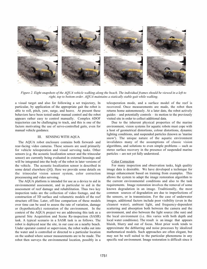
As proposed in [11], our approach is based on learning thestatistical relationships between image pairs. In our case, thesepairs are the images we actually observe and correspondingcolor-corrected and deblurred images. Our approach uses aMarkov Random Field model to learn the statistics from thetraining pairs. This model uses multi-scale representations ofthe corrected (enhanced) and original images to construct aprobabilistic enhancement algorithm that improves theobserved video. This improvement is based on a combinationof color matching, correspondence with training data, andlocal context via belief propagation, all embodies in the
Markov random field. Training images are small patches ofregions of interest that capture the maximum of the intensityvariations from the image to be restored. The correspondingpairs, i.e. the ground truth data containing the restoredinformation from the same regions, are captured when lightsmounted on the robot are turned on. Some experimental resultsare shown in Figure 3.
There are a number of factors that influence the quality ofthe results. These include the adequate amount of reliableinformation as an input and the statistical consistency of theimages in the training sets.
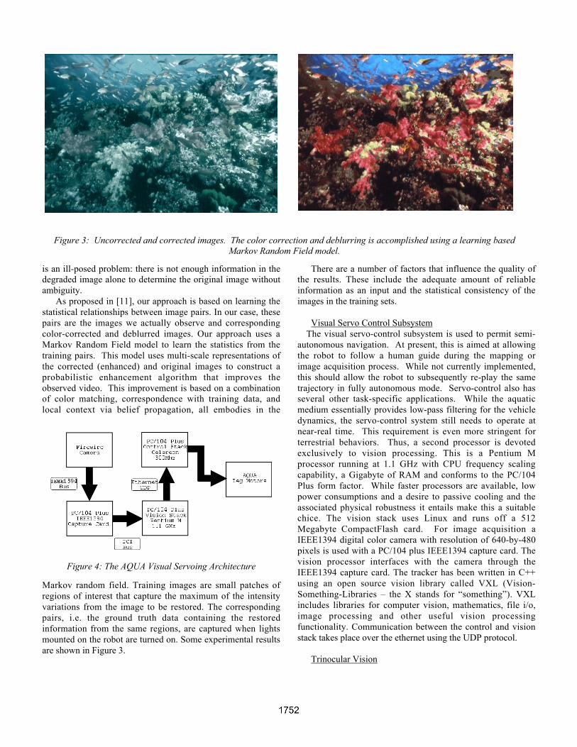
Visual Servo Control SubsystemThe visual servo-control subsystem is used to permit semi-
autonomous navigation. At present, this is aimed at allowingthe robot to follow a human guide during the mapping orimage acquisition process. While not currently implemented,this should allow the robot to subsequently re-play the sametrajectory in fully autonomous mode. Servo-control also hasseveral other task-specific applications. While the aquaticmedium essentially provides low-pass filtering for the vehicledynamics, the servo-control system still needs to operate atnear-real time. This requirement is even more stringent forterrestrial behaviors. Thus, a second processor is devotedexclusively to vision processing. This is a Pentium Mprocessor running at 1.1 GHz with CPU frequency scalingcapability, a Gigabyte of RAM and conforms to the PC/104Plus form factor. While faster processors are available, lowpower consumptions and a desire to passive cooling and theassociated physical robustness it entails make this a suitablechice. The vision stack uses Linux and runs off a 512Megabyte CompactFlash card. For image acquisition aIEEE1394 digital color camera with resolution of 640-by-480pixels is used with a PC/104 plus IEEE1394 capture card. Thevision processor interfaces with the camera through theIEEE1394 capture card. The tracker has been written in C++using an open source vision library called VXL (Vision-Something-Libraries – the X stands for “something”). VXLincludes libraries for computer vision, mathematics, file i/o,image processing and other useful vision processingfunctionality. Communication between the control and visionstack takes place over the ethernet using the UDP protocol.
Trinocular Vision
Figure 3: Uncorrected and corrected images. The color correction and deblurring is accomplished using a learning basedMarkov Random Field model.
Figure 4: The AQUA Visual Servoing Architecture
A fundamental problem with visual sensing in the aquaticdomain is that it is not possible to assume that the sensor onlymoves when commanded to. The aquatic medium is inconstant (and in general unpredictable) motion, and thismotion complicates already difficult problems in time-varyingimage understanding. One mechanism to simplify vision
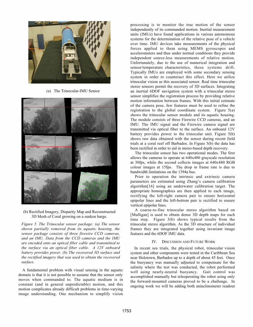
processing is to monitor the true motion of the sensorindependently of its commanded motion. Inertial measurementunits (IMUs) have found applications in various autonomoussystems for the determination of the relative pose of a vehicleover time. IMU devices take measurements of the physicalforces applied to them using MEMS gyroscopes andaccelerometers and thus under normal conditions they provideindependent source-less measurements of relative motion.Unfortunately, due to the use of numerical integration andsensor/temperature characteristics, these systems drift.Typically IMUs are employed with some secondary sensingsystem in order to counteract this effect. Here we utilizetrinocular vision as this associated sensor. Real time trinocularstereo sensors permit the recovery of 3D surfaces. Integratingan inertial 6DOF navigation system with a trinocular stereosensor simplifies the registration process by providing relativemotion information between frames. With this initial estimateof the camera pose, few features must be used to refine theregistration to the global coordinate system. Figure 5(a)shows the trinocular sensor module and its aquatic housing.The module consists of three Firewire CCD cameras, and anIMU. The IMU signal and the Firewire camera signal aretransmitted via optical fiber to the surface. An onboard 12Vbattery provides power to the trinocular unit. Figure 5(b)shows raw data obtained with the sensor during recent fieldtrials at a coral reef off Barbados. In Figure 5(b) the data hasbeen rectified in order to aid in stereo-based depth recovery.
The trinocular sensor has two operational modes. The firstallows the cameras to operate at 640x480 grayscale resolutionat 30fps, while the second collects images at 640x480 RGBcolour images at 15fps. The drop in frame rate is due tobandwidth limitations on the 1394a bus.
Prior to operation the intrinsic and extrinsic cameraparameters are estimated using Zhang’s camera calibrationalgorithm[16] using an underwater calibration target. Theappropriate homographies are then applied to each image,rectifying the left-right camera pair to ensure horizontalepipolar lines and the left-bottom pair is rectified to ensurevertical epipolar lines.
A coarse-to-fine trinocular stereo algorithm based on[Mulligan] is used to obtain dense 3D depth maps for eachtime step. Figure 3(b) shows typical results from thetrinocular stereo algorithm. As the 3D structure of individualframes they are integrated together using invariant imagefeatures and the 6DOF IMU data.
IV. DISCUSSION AND FUTURE WORK
In recent sea trials, the physical robot, trinocular visionsystem and other components were tested in the Caribbean Seanear Holetown, Barbados up to a depth of about 45 feet. Oncethe buoyancy was manually adjusted to compensate for thesalinity where the test was conducted, the robot performedwell using nearly-neutral buoyancy. Gait control wasaccomplished manually but teleoperating the robot using onlythe forward-mounted cameras proved to be a challenge. Inongoing work we will be adding both aninclinometer readout
(a) The Trinocular-IMU Sensor
(b) Rectified Imagery, Disparity Map and Reconstructed3D Mesh of Coral growing on a sunken barge.
Figure 5. The Trinocular sensor package: (a) The sensorshown partially removed from its aquatic housing, thesensor package consists of three firewire CCD cameras,and an IMU. Data from the CCD cameras and the IMUare encoded onto an optical fiber cable and transmitted tothe surface via an optical fiber cable. A 12V onboardbattery provides power. (b) The recovered 3D surface andthe rectified imagery that was used to obtain the recoveredsurface.
and more sophisticated telerobotic control modes to improvemanual controllability.
The vehicle was able to exhibit the full range of swimmingmotions, as well as the previously-tested walking behaviorsdemonstrated on the RHex family of robots. Swimming underthe control of visual servo control was demonstrated to be aneffective control paradigm even in water with limitedvisibility. Initial tests indicated that the vehicle was able tofollow a cooperative free-swimming driver. The tradeoffbetween proximity to a diver, safety, and robustness is an areafor future work. In addition, in preliminary tests ofamphibious operations the vehicle was able to make thetransition from walking to swimming and vice-versa, althoughthis entails skilled manual control and many technical issuesremain to be considered.
The trinocular sensor package was tested on both naturallyoccurring and man-made underwater structures (wrecks andother structures) at different depths and under differentenvironmental conditions. Aquatic snow and other particulatematter provide challenges for traditional stereo algorithms, andwork is currently underway to investigate how to detect andreject invalid matches that occur due to these effects.
One of the key challenges of the project is the extension ofthe SLAM philosophy (Simultaneous Localization andMapping) into motion in three dimensions, with robot posedepending on six degrees of freedom. Much of the SLAMresearch so far has been restricted to three-dimensionalmanifolds, either planar or topographic surfaces, with robotpose depending on three degrees of freedom. Odometryinformation of the same nature as in terrestrial robots isdifficult to obtain in the underwater domain, so one has to relyinstead on an accurate dynamic model of the underwater robotcombined with inertial sensors and sensors of external fields(gravity, earth's magnetic field) to come up with differentialposition estimates for mapping. Furthermore, GPSinformation, which is available to outdoor robots, is notavailable underwater, so the absolute position of theunderwater robot needs to be constrained by its relativeposition with respect to surface vessels with access to GPSsignals. The key sensing modality for mapping in this projectis vision, aiming towards smaller scale mapping than thatbased on sidescan sonar.
ACKNOWLEDGMENTS
We would like to thank Jeff Laurence, Matt Robinson, JimZacher, Michelle Theberges, Dimitri Marinakis, and SidarthVerma. This project was supported by NSERC and by NCEIRIS.
REFERENCES
[1] Altendorfer, R., Moore, N.,Komsuoglu, H., Buehler,M., Brown Jr., H. B., McMordie, D., Saranli, U., Full,R. J. and Koditschek, D. E. "RHex: A BiologicallyInspired Hexapod Runner." Autonomous Robots11:207-213, 2001
[2] Balasuiya, A. and Ura, T., Underwater cable followingby twin-burger 2, Proc. IEEE ICRA, Korea, 2001.
[3] Chen, C.-S., Hung, Y.-P. and Cheng, J.-B.. “A NewApproach to Fast Automatic Registration of PartiallyOverlapping Range Images.” IEEE Transactions onPattern Analysis and Machine Intelligence,21(11):1229-1234, 1999.
[4] Georgiadis, C., German, A., Hogue, A., Liu, H.,Prahacs, C., Ripsman, A., Sim, R., Torres, L.A., Zhang,P., Buehler, M., Dudek, G., Jenkin, M. and Milios, E. "AQUA: An aquatic walking robot." Proceedings of theIEEEE/RSJ/GI International Conference on IntelligentRobots and Systems (IROS), Sendai, Japan, 2004.
[5] Kapralos, B., Jenkin, M. and Milios, E.. Audio-visuallocalization of multiple speakers in a videoteleconferencing setting. International Journal ofImaging Systems and Technology , 13(1):95-105, 2003.
[ 6 ] Luke, B. T. A g g l o m e r a t i v e C l u s t e r i n g.http://fconyx.ncifcrf.gov/~lukeb/agclust.html, lastaccessed on July 8, 2003.
[7] Reid, G. L. and Milios, E. Active stereo soundlocalization. The Journal of the Acoustical Society ofAmerica. 113:185-193, January 2003.
[8] Sharp, G. C., Lee, S. W. and Wehe, D. K. "ICPRegistration using Invariant Features" IEEETransactions on Pattern Analysis and MachineIntelligence, 24(1): 90-102, 2002.
[9] Sim, R. and G. Dudek, "Learning environmentalfeatures for pose estimation", Image and VisionComputing, vol 19, num 11, pp 733-739, Elsevier Press,2001. 733-739, 2001.
[10] Sim, R. and Dudek, G., “Learning Generative Modelsof Scene Features”, Proceedings of the IEEEConference on Computer Vision and PatternRecognition (CVPR), Hawaii, 2001, 7 pages.
[11] Singh, B., Freeman, W. T. and Brainard, D. Exploitingspatial and spectral image regularities for colorconstancy. Workshop on Statistical and ComputationalTheories of Vision. Nice, France, October, 2003.
[12] Stoddart, A. and Hilton, A., Registration of multiplepoint sets, Proc. 13th Int. Conf. on Pattern Recognition,pp B40-44 Vienna, Austria, (1996).
[13] Torres-Mendez, L.-A., and Dudek, G, “Range Synthesisfor 3D Environment Modeling'', Proceedings of theIEEE/RSJ Conference on Intelligent Robots andSystems (IROS), Las Vegas, NV, Oct. 2003, 8 pages.
[14] Triggs, B., McLauchlan, P., Hartley, R. andFitzgibbon. A. Vision Algorithms: Theory and Practice.Triggs, W., Zisserman, A. and Szeliski, R. (Eds.)Springer Verlag, 2000, p. 298-375.
[15] Xu, X. and Negahdaripour, S., Vision-based motionsensing for underwater navigation and mosaicing ofocean floor images. Proc. IEEE Oceans’97, 1412-1417,1997, Halifax, NS.
[16] Zhang, Z. A Flexible new technique for cameracalibration. Technical Report MSR-TR-98-71,Microsoft Research, 1998.