Embed Size (px)
Citation preview
Towards Direct Head Navigation for robot-guided TranscranialMagnetic Stimulation using 3D Laserscans: Idea, Setup and Feasibility
Lars Richter, Ralf Bruder, Alexander Schlaefer and Achim Schweikard
Abstract— Direct tracking is more robust than tracking thatis based on additional markers. 3D laser scans can be used fordirect tracking because they result in a 3D data set of surfacepoints of the scanned object. For head-navigated robotizedsystems, it is crucial to know where the patient’s head ispositioned relatively to the robot. We present a novel methodto use a 3D laserscanner for direct head navigation in therobotized TMS system that places a coil on the patient’s headusing an industrial robot. First experimental results showed atranslational error < 2 mm in the robot hand-eye-calibrationwith the laserscanner. The rotational error was 0.75◦ and thescaling error < 0.001. Furthermore, we found that the error ofa scanned head to a reference head image was < 0.2 mm usingICP. These results have shown that a direct head navigation isfeasible for the robotized TMS system. Additional effort has tobe made in future systems to speed up the compution time forreal time capability.
I. INTRODUCTION
For the robotized Transcranial Magnetic Stimulation(TMS) system, a magnetic coil is placed directly on topof a patient’s head by the robot being able to induce anelectric current in a predefined region of the brain [1]. Theaim of TMS is to stimulate the brain non-invasively andpainlessly. Besides usage as a diagnostic tool, TMS is usedas a treatment attempt in different neurological diseases, e.g.depression, chronic tinnitus or chronic pain [2].
Navigated TMS is currently the state of the art method inTMS research and is available in many TMS systems [3].Robotized systems for TMS are advancing forward and areclaimed more and more for an exact stimulation with TMS[4].
For a head-navigated robotized system it is crucial to knowwhere the patient’s head is positioned in relation to to therobot. The common method to navigate is to use a headbandwith a marker and an optical tracking system. In our systemthe headband is tracked by a Polaris Spectra infrared camera(Northern Digital Inc., Waterloo, Ontario, Canada). An AdeptViper s850 serial industrial robot (Adept Technology, Inc.,
This work was partially supported by the Graduate School for Computingin Medicine and Life Sciences funded by Germany’s Excellence Initiative[DFG GSC 235/1].
L. Richter, R. Bruder and A. Schweikard are with the Institute forRobotics and Cognitive Systems, University of Lubeck, 23538 Lubeck,Germany
A. Schlaefer is with the Medical Robotics Group, University of Lubeck,23538 Lubeck, Germany
L. Richter and A. Schlaefer are also with the Graduate School forComputing in Medicine and Life Sciences, University of Lubeck, 23538Lubeck, Germany{richter,bruder,schlaefer,schweikard}@rob.uni-luebeck.de
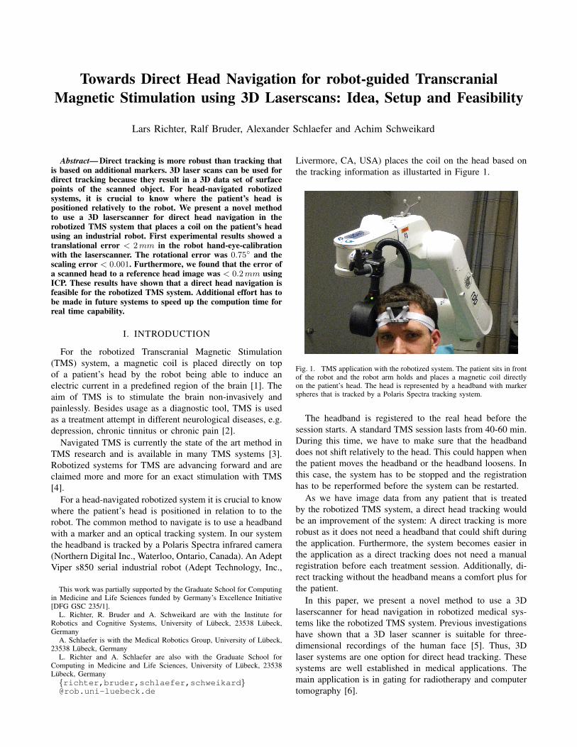
Livermore, CA, USA) places the coil on the head based onthe tracking information as illustarted in Figure 1.
Fig. 1. TMS application with the robotized system. The patient sits in frontof the robot and the robot arm holds and places a magnetic coil directlyon the patient’s head. The head is represented by a headband with markerspheres that is tracked by a Polaris Spectra tracking system.
The headband is registered to the real head before thesession starts. A standard TMS session lasts from 40-60 min.During this time, we have to make sure that the headbanddoes not shift relatively to the head. This could happen whenthe patient moves the headband or the headband loosens. Inthis case, the system has to be stopped and the registrationhas to be reperformed before the system can be restarted.
As we have image data from any patient that is treatedby the robotized TMS system, a direct head tracking wouldbe an improvement of the system: A direct tracking is morerobust as it does not need a headband that could shift duringthe application. Furthermore, the system becomes easier inthe application as a direct tracking does not need a manualregistration before each treatment session. Additionally, di-rect tracking without the headband means a comfort plus forthe patient.
In this paper, we present a novel method to use a 3Dlaserscanner for head navigation in robotized medical sys-tems like the robotized TMS system. Previous investigationshave shown that a 3D laser scanner is suitable for three-dimensional recordings of the human face [5]. Thus, 3Dlaser systems are one option for direct head tracking. Thesesystems are well established in medical applications. Themain application is in gating for radiotherapy and computertomography [6].
Besides describing the idea and setup of the head naviga-tion method, we show the feasibility of the method with firstexperimental results.
II. METHODS
The direct head navigation for the robotized TMS systemusing laserscans is based on three steps: First, a calibrationfrom laserscanner to robot has to be performed. Second, theTMS coil (or tool in general) has to be registered for a precisepositioning and stimulation. In a third step, the laserscanneris used for position acquisition.
A. System-set-up
We use a GALAXY laser system (LAP GmbH Laser Ap-plikationen, Luneburg, Germany) as a tracking system for thehead navigation. Furthermore, we use an Adept Viper s850serial industrial robot (Adept Technology, Inc., Livermore,CA, USA). For testing, we use a human head phantom thatis mounted to the robot endeffector. The robot calibration isperformed with the usage of a phantom provided with theGALAXY system.
The GALAXY laserscanner has a scan volume of 670 −800 × 950 − 1300 × 490 − 600 mm3. The scanning timedepends on the resolution and on the size of scanningvolume. The time needed to perform one scan is in the rangeof 1− 5 s. With a reduced resolution and in real time mode,the laser system can reach a scanning frequency up to 5 Hz.The scanner has a repeatability of < 0.1 mm and an accuracyin the acquired patient position of < 1 mm. The resolutionin the measurement axis of the laserscanner is specified with0.2 mm for the y- and z-axis, and with 0.5 mm for the x-axis[7].
B. Calibration of robot to 3D laserscanner
(a) (b)
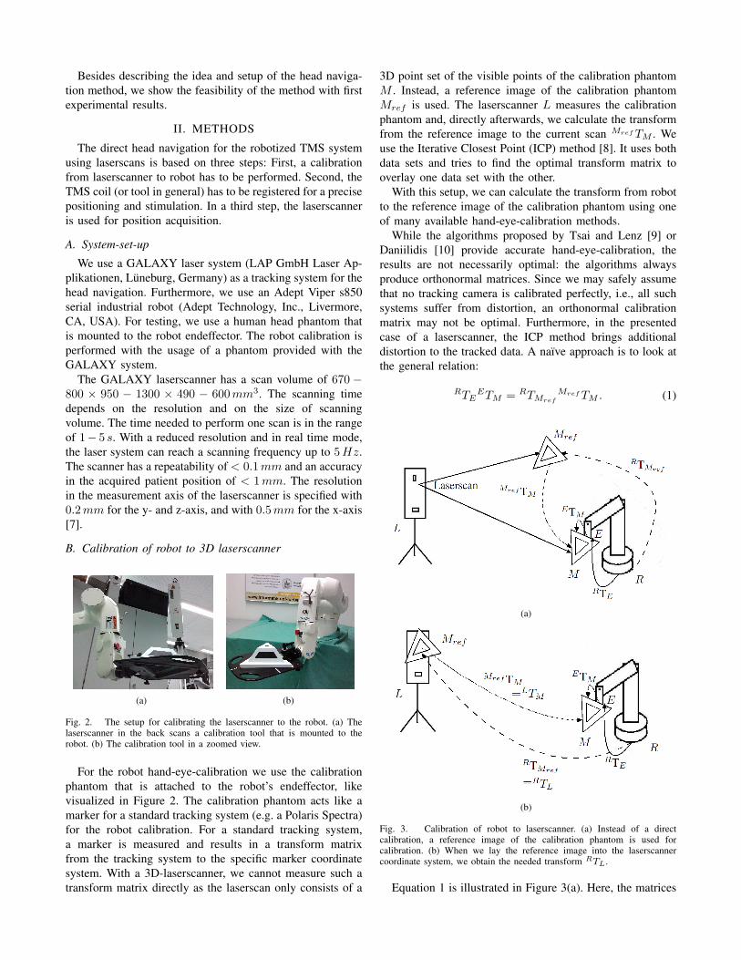
Fig. 2. The setup for calibrating the laserscanner to the robot. (a) Thelaserscanner in the back scans a calibration tool that is mounted to therobot. (b) The calibration tool in a zoomed view.
For the robot hand-eye-calibration we use the calibrationphantom that is attached to the robot’s endeffector, likevisualized in Figure 2. The calibration phantom acts like amarker for a standard tracking system (e.g. a Polaris Spectra)for the robot calibration. For a standard tracking system,a marker is measured and results in a transform matrixfrom the tracking system to the specific marker coordinatesystem. With a 3D-laserscanner, we cannot measure such atransform matrix directly as the laserscan only consists of a
3D point set of the visible points of the calibration phantomM . Instead, a reference image of the calibration phantomMref is used. The laserscanner L measures the calibrationphantom and, directly afterwards, we calculate the transformfrom the reference image to the current scan Mref TM . Weuse the Iterative Closest Point (ICP) method [8]. It uses bothdata sets and tries to find the optimal transform matrix tooverlay one data set with the other.
With this setup, we can calculate the transform from robotto the reference image of the calibration phantom using oneof many available hand-eye-calibration methods.
While the algorithms proposed by Tsai and Lenz [9] orDaniilidis [10] provide accurate hand-eye-calibration, theresults are not necessarily optimal: the algorithms alwaysproduce orthonormal matrices. Since we may safely assumethat no tracking camera is calibrated perfectly, i.e., all suchsystems suffer from distortion, an orthonormal calibrationmatrix may not be optimal. Furthermore, in the presentedcase of a laserscanner, the ICP method brings additionaldistortion to the tracked data. A naıve approach is to look atthe general relation:
RTEETM = RTMref
Mref TM . (1)
(a)
(b)
Fig. 3. Calibration of robot to laserscanner. (a) Instead of a directcalibration, a reference image of the calibration phantom is used forcalibration. (b) When we lay the reference image into the laserscannercoordinate system, we obtain the needed transform RTL.
Equation 1 is illustrated in Figure 3(a). Here, the matrices
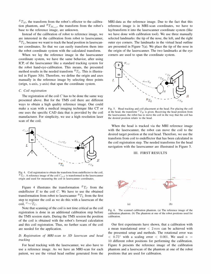
ETM , the transform from the robot’s effector to the calibra-tion phantom, and RTMref
, the transform from the robot’sbase to the reference image, are unknown.
Instead of the calibration of robot to reference image, weare interested in the calibration from robot to laserscanner,RTL, because we want to track the head position in laserscan-ner coordinates. So that we can easily transform them intothe robot coordinate system with the calculated transform.
When we lay the reference image in the laserscannercoordinate system, we have the same behavior, after usingICP, of the laserscanner like a standard tracking system forthe robot hand-eye-calibration. This means, the presentedmethod results in the needed transform RTL. This is illustra-ted in Figure 3(b). Therefore, we define the origin and axesmanually in the reference image by selecting three points(orign, x-axis, y-axis) that span the coordinate system.
C. Coil registration
The registration of the coil C has to be done the same waypresented above. But for the TMS coil there are differentways to obtain a high quality reference image. One couldmake a scan with a medical imaging technique like CT orone uses the specific CAD data that is provided by the coilmanufacturer. For simplicity, we use a high resolution laserscan of the coil.
Fig. 4. Coil registration to obtain the transform from endeffector to the coil,ETC . A reference image of the coil Cref is transformed in the laserscannerorigin and used for measuring the coil in laserscanner coordinates.
Figure 4 illustrates the transformation ETC from theendeffector E to the coil C. We have to use the obtainedtransformation from robot to laserscanner RTL from the firststep to register the coil as we do this with a laserscan of thecoil, Cref TC .
Note that scanning of the coil is not time critical as the coilregistration is done in an additional calibration step beforethe TMS session starts. During the TMS session the positionof the coil is obtained with the robot’s forward calculationand this coil registration. Thus, no further scans of the coilare needed for the application.
D. Registration of MRI-scan to 3D laserscan and headtracking
For head tracking with the laserscanner, we also have touse a reference image. As we have an MRI-scan for eachpatient, we use the virtual head outline generated from the
MRI-data as the reference image. Due to the fact that thisreference image is in MRI-scan coordinates, we have tolay/transform it into the laserscanner coordinate system (likewe have done with calibration tool). We use three manuallyselected landmarks: the tip of the nose, the left, and the rightouter eye corners. The landmarks in the virtual head outlineare presented in Figure 7(a). We place the tip of the nose inthe origin of the laserscanner. The two landmarks at the eyecorners are used to span the coordinate system.
Fig. 5. Head tracking and coil placement at the head. For placing the coilat the head, the transform CTH is given. Receiving the head position fromthe laserscanner, the robot has to move the coil in the way that the coil hasthe desired position relativ to the head.
When the head is tracked via the MRI reference imagewith the laserscanner, the robot can move the coil to thedesired target position at the real head. Therefore, we use thetransform from coil to endeffector that has been calculated inthe coil registration step. The needed transforms for the headnavigation with the laserscanner are illustrated in Figure 5.
III. FIRST RESULTS
(a) (b)
Fig. 6. The scanned calibration phantom. (a) The reference image of thecalibration phantom. (b) The phantom at one of the robot positions used forcalibration.
Our first experiments have shown, that a calibration witha mean translational error < 2 mm can be achieved withthe presented setup and methods. The rotational error was< 0.75◦ with a scaling error < 0.001. We used n =10 different robot positions for performing the calibration.Figure 6 presents the reference image of the calibrationphantom and a laserscan of the phantom at one of the robotpositions that are used for calibration.
(a) (b)
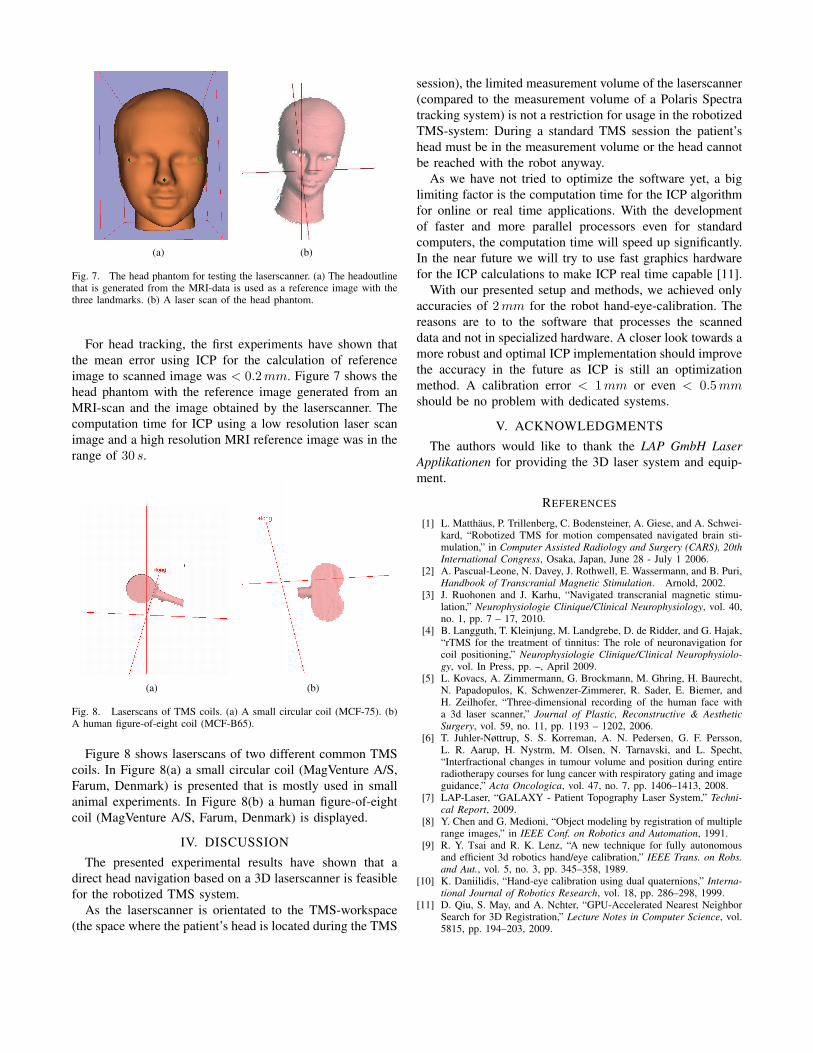
Fig. 7. The head phantom for testing the laserscanner. (a) The headoutlinethat is generated from the MRI-data is used as a reference image with thethree landmarks. (b) A laser scan of the head phantom.
For head tracking, the first experiments have shown thatthe mean error using ICP for the calculation of referenceimage to scanned image was < 0.2 mm. Figure 7 shows thehead phantom with the reference image generated from anMRI-scan and the image obtained by the laserscanner. Thecomputation time for ICP using a low resolution laser scanimage and a high resolution MRI reference image was in therange of 30 s.
(a) (b)
Fig. 8. Laserscans of TMS coils. (a) A small circular coil (MCF-75). (b)A human figure-of-eight coil (MCF-B65).
Figure 8 shows laserscans of two different common TMScoils. In Figure 8(a) a small circular coil (MagVenture A/S,Farum, Denmark) is presented that is mostly used in smallanimal experiments. In Figure 8(b) a human figure-of-eightcoil (MagVenture A/S, Farum, Denmark) is displayed.
IV. DISCUSSION
The presented experimental results have shown that adirect head navigation based on a 3D laserscanner is feasiblefor the robotized TMS system.
As the laserscanner is orientated to the TMS-workspace(the space where the patient’s head is located during the TMS
session), the limited measurement volume of the laserscanner(compared to the measurement volume of a Polaris Spectratracking system) is not a restriction for usage in the robotizedTMS-system: During a standard TMS session the patient’shead must be in the measurement volume or the head cannotbe reached with the robot anyway.
As we have not tried to optimize the software yet, a biglimiting factor is the computation time for the ICP algorithmfor online or real time applications. With the developmentof faster and more parallel processors even for standardcomputers, the computation time will speed up significantly.In the near future we will try to use fast graphics hardwarefor the ICP calculations to make ICP real time capable [11].
With our presented setup and methods, we achieved onlyaccuracies of 2 mm for the robot hand-eye-calibration. Thereasons are to to the software that processes the scanneddata and not in specialized hardware. A closer look towards amore robust and optimal ICP implementation should improvethe accuracy in the future as ICP is still an optimizationmethod. A calibration error < 1 mm or even < 0.5 mmshould be no problem with dedicated systems.
V. ACKNOWLEDGMENTS
The authors would like to thank the LAP GmbH LaserApplikationen for providing the 3D laser system and equip-ment.
REFERENCES
[1] L. Matthaus, P. Trillenberg, C. Bodensteiner, A. Giese, and A. Schwei-kard, “Robotized TMS for motion compensated navigated brain sti-mulation,” in Computer Assisted Radiology and Surgery (CARS), 20thInternational Congress, Osaka, Japan, June 28 - July 1 2006.
[2] A. Pascual-Leone, N. Davey, J. Rothwell, E. Wassermann, and B. Puri,Handbook of Transcranial Magnetic Stimulation. Arnold, 2002.
[3] J. Ruohonen and J. Karhu, “Navigated transcranial magnetic stimu-lation,” Neurophysiologie Clinique/Clinical Neurophysiology, vol. 40,no. 1, pp. 7 – 17, 2010.
[4] B. Langguth, T. Kleinjung, M. Landgrebe, D. de Ridder, and G. Hajak,“rTMS for the treatment of tinnitus: The role of neuronavigation forcoil positioning,” Neurophysiologie Clinique/Clinical Neurophysiolo-gy, vol. In Press, pp. –, April 2009.
[5] L. Kovacs, A. Zimmermann, G. Brockmann, M. Ghring, H. Baurecht,N. Papadopulos, K. Schwenzer-Zimmerer, R. Sader, E. Biemer, andH. Zeilhofer, “Three-dimensional recording of the human face witha 3d laser scanner,” Journal of Plastic, Reconstructive & AestheticSurgery, vol. 59, no. 11, pp. 1193 – 1202, 2006.
[6] T. Juhler-Nøttrup, S. S. Korreman, A. N. Pedersen, G. F. Persson,L. R. Aarup, H. Nystrm, M. Olsen, N. Tarnavski, and L. Specht,“Interfractional changes in tumour volume and position during entireradiotherapy courses for lung cancer with respiratory gating and imageguidance,” Acta Oncologica, vol. 47, no. 7, pp. 1406–1413, 2008.
[7] LAP-Laser, “GALAXY - Patient Topography Laser System,” Techni-cal Report, 2009.
[8] Y. Chen and G. Medioni, “Object modeling by registration of multiplerange images,” in IEEE Conf. on Robotics and Automation, 1991.
[9] R. Y. Tsai and R. K. Lenz, “A new technique for fully autonomousand efficient 3d robotics hand/eye calibration,” IEEE Trans. on Robs.and Aut., vol. 5, no. 3, pp. 345–358, 1989.
[10] K. Daniilidis, “Hand-eye calibration using dual quaternions,” Interna-tional Journal of Robotics Research, vol. 18, pp. 286–298, 1999.
[11] D. Qiu, S. May, and A. Nchter, “GPU-Accelerated Nearest NeighborSearch for 3D Registration,” Lecture Notes in Computer Science, vol.5815, pp. 194–203, 2009.