Embed Size (px)
Citation preview

Research ArticleA Lower Limb Rehabilitation Robot in Sitting Position with aReview of Training Activities
Trinnachoke Eiammanussakul and Viboon Sangveraphunsiri
Department of Mechanical Engineering, Faculty of Engineering, Chulalongkorn University, Bangkok, Thailand
Correspondence should be addressed to Viboon Sangveraphunsiri; [email protected]
Received 17 November 2017; Revised 3 February 2018; Accepted 20 February 2018; Published 1 April 2018
Academic Editor: Rafael Morales
Copyright © 2018 Trinnachoke Eiammanussakul and Viboon Sangveraphunsiri. This is an open access article distributed under theCreative Commons Attribution License, which permits unrestricted use, distribution, and reproduction in any medium, providedthe original work is properly cited.
Robots for stroke rehabilitation at the lower limbs in sitting/lying position have been developed extensively. Some of them havebeen applied in clinics and shown the potential of the recovery of poststroke patients who suffer from hemiparesis. These robotswere developed to provide training at different joints of lower limbs with various activities and modalities. This article reviewsthe training activities that were realized by rehabilitation robots in literature, in order to offer insights for developing a novelrobot suitable for stroke rehabilitation. The control system of the lower limb rehabilitation robot in sitting position that wasintroduced in the previous work is discussed in detail to demonstrate the behavior of the robot while training a subject. Thenonlinear impedance control law, based on active assistive control strategy, is able to define the response of the robot with morespecifications while the passivity property and the robustness of the system is verified. A preliminary experiment is conductedon a healthy subject to show that the robot is able to perform active assistive exercises with various training activities and assistthe subject to complete the training with desired level of assistance.
1. Introduction
Robots for rehabilitation have gained more attentions inmany research due to some benefits over conventional ther-apy by physiotherapists. For example, robots for locomotiontraining on a treadmill primarily aim to replace physicaldemand of the therapist labor because the task is ergonomi-cally unfavorable and tiring [1]. Without physical burden,numbers of repetition and duration of the training sessioncan be increased [2–4]. While the performance of a therapistcould vary from day to day [1] and intervention techniquesby expert and unexperienced therapists are different [5, 6],a robot follows the certain control algorithm and providessystematic intervention to the patient. Moreover, robots areable to obtain and record data such as position, velocity,interaction force, or biosignal with various kinds of sensors.This quantitative data can be used for further offline analysis,which leads to objective evaluation of the patient’s recovery[3, 4], or even used for adapting robot’s behavior correspond-ing the patient’s current condition. Rehabilitation robots arealso able to perform different types of exercises and varieties
of movement [2, 7, 8]. Moreover, the robot can be imple-mented with games [9] or virtual reality system [10] in orderto promote active participation of the patient. Robots forstroke rehabilitation have shown their effectiveness in manyclinical trials worldwide.
The lower limb rehabilitation robots can be categorizedinto 2 types according to exercise posture [11]. The first typeis a robot for training in sitting/lying position which benefitsthe patient who still suffers from muscle weakness and can-not stand or walk safely [5, 12]. By excluding concern of bal-ance, the patient may be more independent and able to focuson the training [13]. This kind of robot allows the patient tostrengthen muscle, develop endurance, and increase jointmobility and movement coordination [4]. Another type ofthe robot is for training while standing/walking. The gaittraining robot in literature was developed to train either overground or on a treadmill with a body weight support mecha-nism. However, the gait training robot is only suitable for thepatient that has adequate endurance and ability to stand [14].
Training modalities used in robots for stroke rehabilita-tion are often divided into four groups, namely, passive,
HindawiJournal of Healthcare EngineeringVolume 2018, Article ID 1927807, 18 pageshttps://doi.org/10.1155/2018/1927807
active assistive, active, and active resistive exercises [15].Exercises may be prescribed to a stroke patient correspond-ing to the stage of recovery [3] and the muscle tone [2, 16],which can be graded according to the muscle contractionobservability, ability to move a limb against gravity andexternal resistance [17]. In the preliminary stage, the patientwith very low muscle strength should conduct passive train-ing, for example, moving the patient’s limb along a prede-fined trajectory by another person or an exercise deviceknown as continuous passive machine (CPM). Passive exer-cise could improve movement ability, maintain range ofmotion, and reduce muscle atrophy. In the intermediatestage, the patient with some degree of muscle strength shouldperform active assistive, active, or active resistive exercise.Active assistive exercise allows the patient to move the limbby himself with assistance provided by another person whenneeded. Active exercise allows the patient to move by his owneffort without external assistance and resistance. In activeresistive mode, the robot provides force opposing the move-ment of the patient. This exercise aims to strengthen muscleof the patient who is already able to move his limb over thefull range of motion. Different motion and amount of resis-tive force can be applied to achieve a variety of strengtheningtraining such as isometric, isotonic, and isokinetic exercise.There are many types of force that could be applied to thepatient as resistance. Resistive exercise in conventionalrehabilitation can be done against weight, elastic bands, inthe pool, or by an exercise machine [14]. In the advancedrehabilitation stage, the objective of the exercise is to regainfunction related to activities in daily living such as balancingand gait training.
Apart from training modalities, training activities alsohave to be selected appropriately to an individual. Becausethe lower limb rehabilitation robots in sitting/lying positionget rid of the stability concern, the robots are able to performa variety of training activities. It is interesting to studyhow these training activities are selected and what are ben-efits of each training activity for a stroke patient. Thisknowledge would be useful in developing robots suitablefor stroke rehabilitation.
This article focuses on the lower limb rehabilitationrobots for training in sitting/lying position. In Section 2, thetraining activities performed by this type of robot arereviewed. Description of the robot is shown in Section 3.The control system and the impedance control law proposedin our previous work [18] for active assistive exercises arediscussed in Section 4. Experiments conducted to study theperformance of the system are also presented in this section.The experiment by a healthy subject in Section 5 demon-strates the robot behavior while performing training activi-ties with many levels of assistance. Finally, the conclusionof the research article is made on Section 6.
2. Review of Training Activities of Robots forStroke Rehabilitation
Training activities performed by lower limb stroke rehabilita-tion robots in sitting/lying position are summarized inTable 1. Types and actuated degrees of freedom of the robots
are also reported since they are corresponding to the trainingactivities. Foot robotic orthoses and footplate-based end-effector robots are able to actuate only at ankle joint and footsection. End-effector robots (nonfootplate-based type) areusually able to perform movements involving hip, knee,and ankle joints in the sagittal plane. On the other hand, exo-skeletons whose structure and joint axes aligned with those ofhuman body are able to perform the movement of a singlejoint or multiple joints.
Robots in lower limb rehabilitation after stroke are devel-oped with different concepts of the training. Some robots areable to perform a certain training activity and modality.Anklebot [19] is able to train ankle joint with active assistivetraining modality while the lower limb paediatric therapydevice by Chrif et al. [20] was designed for leg press exerciseperforming with active resistive training modality. Besides,some robots can perform many training activities but witha certain training modality. For example, the horizontallower limb rehabilitation training robot by Guo et al. [5] isable to train lower limbs in six actions according to the tradi-tional Chinese medicine technique with passive trainingmodality, whereas ViGRR [21] can perform gait trajectoryfollowing and leg press exercise with active resistive trainingmodalities. Moreover, some robots are able to perform onlyone training activity but with various kinds of trainingmodality. MOTOmed [22] can perform cycling exercise withpassive, active assistive, and active resistive training modali-ties while Vi-RABT [12] can train ankle joint with activeassistive and active training modalities. The other robotsare able to perform many training activities and modalities.The ankle rehabilitation robot by Yoon et al. [7] is able totrain ankle joint or perform gait trajectory following at theankle joint with passive, active assistive, and active resistivetraining modalities. Physiotherabot [2] is able to performmany training activities at hip and knee joints with passive,active assistive, and active resistive trainingmodalities. Lowerlimb rehabilitation robot in our previous research [18] can beused for therapeutic exercises at hip, knee, and ankle joints.Because the robot structure is exoskeleton, it can performboth single- and multiple-joint training. The desired trajec-tory of the robot can be easily customized. Therefore, range,pattern, and speed of the movement can be arbitrarilyadjusted to suit with the patient condition. It is also able toperform passive, active assistive, and active resistive trainingmodalities. The robot is designed for versatile training for astroke patient in sitting position.
According to Table 2, training activities can be catego-rized as single-joint training and multiple-joint training.The single-joint training involves the movement of a spe-cific joint (hip, knee, or ankle joint) in one or severaldegrees of freedom. It can be performed by foot roboticorthoses, footplate-based end-effector robots, and exoskele-tons. On the other hand, the multiple-joint trainingconsists of the simultaneous movement of several jointsfor performing exercises such as leg press, cycling, and gaittrajectory following. Some robots are able to perform acustomized movement by using recorded data (e.g., posi-tion, velocity, and interaction force) obtained during therobot teaching session by a physiotherapist. The multiple-
2 Journal of Healthcare Engineering

joint training can be conducted by end-effector robotsand exoskeletons.
Single-joint training is usually selected for range ofmotion exercise which can be performed with passive, activeassistive, or active training modalities. In addition, single-joint training is also chosen when improvement of functionalability of a specific joint is required. For example, the anklejoint is targeted for the training by some rehabilitation robotsbecause stroke patients are usually unable to activate dorsi-flexor muscle to lift the foot up. This problem leads to walk-ing impairments of the patients such as toe dragging in theswing phase and foot slapping in the heel strike phase.Besides, the patients might have excessive inversion whichcauses lateral instability in the stance phase of the gait [19].Anklebot and Vi-RABT apply active assistive trainingmodality to provide assistance to a patient while using the
robots to move a cursor in computer games. The benefits ofthe training are supported by results of clinical trials onchronic stroke patients with Anklebot. It was shown thatthe patients had better motor control (increased targetingaccuracy and faster and smoother movements) and walkingability (increased walking velocity, durations of paretic singlesupport, and nonparetic step length which could be a resultfrom greater push-off of the paretic foot) [23–25].
There are varieties of exercise that involve training ofmultiple joints such as leg press, cycling, gait trajectory fol-lowing and customized movement. The developers of therobots selected one or several kinds of these exercises toachieve different aspects of the stroke recovery.
Leg press exercise is extensively used in sport and neu-romuscular rehabilitation. It aims to strengthen musclesacross multiple joints of the lower limbs in sitting/lying
Table 1: Training activities of stroke rehabilitation robot in sitting/lying position.
Robot Robot type Actuated DOFs Training activities Training modalities
AnklebotFoot roboticorthosis
Ankle dorsiflexion/plantarflexion, inversion/eversion
Training at ankle joint Active assistive
Vi-RABTFootplate-basedend-effector robot
Ankle dorsiflexion/plantarflexion, inversion/eversion
Training at ankle jointActive assistive,
active
Ankle rehabilitationrobot by Yoon et al.
Footplate-basedend-effector robot
Ankle dorsiflexion/plantarflexion, inversion/eversion,
metatarsophalangealflexion/extension
Training at ankle joint,gait trajectory following
Passive, activeassistive, active
resistive
Lower limb paediatrictherapy device by Chrif et al.
End-effectorrobot
Movement in sagittal plane Leg press Active resistive
Horizontal lower limbrehabilitation trainingrobot by Guo et al.
End-effectorrobot
Movement in sagittal plane,ankle internal/external
rotation
Training at single/multiplejoints
Passive
ViGRREnd-effector
robotMovement in sagittal plane
Gait trajectory following,leg press
Active resistive
MOTOmedEnd-effector
robotMovement in sagittal plane Cycling
Passive, activeassistive,
active resistive
Physiotherabot ExoskeletonHip flexion/extension,abduction/adduction,knee flexion/extension
Training at single/multiplejoints, customized movement
Passive,active assistive,active resistive
Lower limb rehabilitationrobot in our previousresearch
ExoskeletonHip flexion/extension,knee flexion/extension,ankle flexion/extension
Training at single/multiplejoints, customized movement
Passive,active assistive,active resistive
Table 2: Training modalities implemented in each training activity.
Training activityTraining modalities
Passive Active assistive Active Active resistive
Single-joint training (at hip, knee, or ankle joint) x x x x
Multiple-joint training
Leg press x
Cycling x x x
Gait trajectory following x
Customized movement x
3Journal of Healthcare Engineering

position [26]. This exercise is able to activate leg muscles in asimilar level compared to bodyweight exercises such as chairrise and hip thrust [27]. Moreover, it is found that chronicstroke patients not only gain strength on both affected andnonaffected legs but also have improvement in balance, walk-ing ability, and functional performance [28, 29].
Cycling is an alternative exercise to walking for strokepatients who have difficulty in maintaining balance andindependent gait [30]. It provides continuous repetitions ofmovement which promotes coordination of muscle syner-gies. Its kinematic pattern is also similar to walking as itrequires flexion and extension of hip, knee, and ankle jointsas well as activation of antagonist muscles in alternatingand coordinated manner. In addition, because the range ofmotion in cycling is greater than that in walking, cyclingcould help maintaining functional range of motion as a prep-aration for gait training in the future [31]. It was found thatthe stationary cycling training is able to enhance dynamic bal-ance, muscle strength, and walking ability of chronic strokepatients [30]. MOTOmed, which was specifically designedfor cycling exercise, had been used in clinical trials on strokepatients. It was found that stroke patients who performedresistive exercise with the device had improvement in walkingdistance in 2 and 6 minutes walking test, increase in comfort-able speed, and lower time spent on “Up & Go” test [22].
Walking is a functional task of lower limbs and the goalof rehabilitation. However, the task consists of complexmovement that requires force generation for body weightsupport, coordination, and weight shifting [31]. Gait trainingof a stroke patient who still suffers from muscle weaknessdemands great physical effort from both the patient and sev-eral physiotherapists. Therefore, duration and numbers ofrepetition in a gait training session in an upright positionmight not be enough to gain effective rehabilitation outcome[1]. Some robots are able to perform gait training for strokepatients in sitting/lying position. These robots recorded gaittrajectories from healthy subjects to create a reference datafor training stroke patients. The ankle rehabilitation robotby Yoon et al. performs isokinetic exercise by following ankleand foot (metatarsophalangeal joint) reference trajectory. Onthe other hand, ViGRR implements resistive exercise againstvirtual damping and inertia to interact with the patient dur-ing the gait trajectory following task.
Because physical characteristics may differ among strokepatients and from day to day, the training should be custom-ized individually at the beginning of each training session.Physiotherabot was developed to train a stroke patient withany movement pattern taught by a physiotherapist. Oncethe movement is recognized, the robot will train a strokepatient with that movement as if the training is performedby a physiotherapist.
3. Lower Limb Rehabilitation Robot
The lower limb rehabilitation robot in this project is devel-oped for movement training in sitting position. It aims tobe used by patients who have severe hemiparesis condition.These patients are not comfortable to use typical treadmilltraining devices at the beginning of training activities. The
sitting position robot is more preferable especially at thebeginning state of training. The lower limb rehabilitationrobot in this study as shown in Figure 1 consists of a poweredexoskeleton, a counterbalance mechanism, a control unit,and a monitor screen (not shown in the figure).
The exoskeleton is able to move in the sagittal plane athip, knee, and ankle joints. The hip joint allows 45° flexionand 0° extension. The knee joint is able to move in the rangeof 110° flexion and 0° extension. The ankle joint permits 20°
dorsiflexion and 45° plantar flexion. These ranges of motionare ensured by mechanical stoppers placed at the end of thejoint movement range.
Figure 2 illustrates components of the cable transmissionmechanism of a robot joint (the knee joint is shown, e.g.).The mechanism is actuated by a brushless servomotor(SANYO DENKI). Sizes of the motors are 400W for hipand knee joints and 200W for the ankle joint. Specificationsof the motors are provided in Table 3. The pulley A, which ismounted at the end of the motor shaft, drives the pulley B viacable. The second stage of the cable transmission is done bythe shaft connected to the pulley B. Another end of this shaftworks as a small pulley for driving the pulley C via cable.With the shaft connected between the pulley C and the shanksegment, the shank segment rotates about the knee joint axiswith respect to the pulley C.
The torque requirements (maximum torque) of hip andknee joints are considered when lower limbs stretch out insitting position while the torque requirement for the anklejoint is considered at neutral sitting position. According toanthropomorphic data [32], for a human with 100 kg weightand 180 cm height, torque requirements for hip, knee, andankle joints are 67.331, 18.598, 1.945N·m, respectively. Forthe robot joint design, transmission ratios of hip, knee, andankle joints are chosen so that continuous torque providedby the robot joints is sufficient for the torque requirements.Specifications of the robot joints are shown in Table 4.
To achieve backdrivability of the robot joints, the inertiaof the corresponding robot segment must be lower than thereflected motor inertia (the product of the square of thetransmission ratio and the inertia of the motor) [33]. Theranges of inertia of thigh, shank, and foot segments accordingto their minimum and maximum lengths are given inTable 5. It can be noticed that the reflected motor inertiasof hip, knee, and ankle joints are always lower than themoments of inertia of thigh, shank, and foot segments abouttheir proximal joint axes, respectively. Therefore, it can beconcluded that the robot joints are backdrivable.
The counterbalance mechanism is designed to reduceeffects of the gravitational load due to robot’s weight. Themechanism consists of vertical guide rods, linear bearings, a12 kg mass, and a cable which wraps around a series of idlersto link the thigh segment of the exoskeleton and the 12 kgmass together. The guide rods and idlers are mounted onthe control unit. The weight of the 12 kg mass generatescounterbalance moment about the hip joint whose magni-tude corresponds to the hip joint angle in order to counteractthe moment due to robot’s weight. With this counterbalancemechanism, the torque requirement of the hip joint trans-mission mechanism is reduced up to 20.7N·m.
4 Journal of Healthcare Engineering

Both the exoskeleton and the counterbalance mecha-nism are installed on the control unit as a single platform.The control unit also contains a DC power supply, a
computer unit, a data acquisition card, motor amplifiers,an emergency stop button, and other electronic devices.
4. Control System
The lower limb rehabilitation robot is developed to train asubject with various training activities and modalities.Control algorithm for each training modality had beenintroduced in the previous work [18]. In this study, thecontrol algorithm for active assistive exercise is describedin more detail.
Hip joint axis
Knee joint axis
Ankle joint axis
Counterbalancemechanism
Control unit
Exoskeleton
Figure 1: Lower limb rehabilitation robot in sitting position consisted of an exoskeleton (with hip, knee, and ankle joints), the counterbalancemechanism, and the control unit.
Brushless servomotor
Thigh segment
Pulley B
Pulley A
Pulley C
Shank segment
Knee joint axis
Figure 2: Cable transmission mechanism of the knee joint.
Table 3: Specifications of brushless servomotors.
Power(W)
Peak stalltorque(N·m)
Ratedtorque (N·m)
Ratedspeed (rpm)
Inertia× 10−4 kg ⋅m2
400 4.8 1.27 3000 0.412
200 2.2 0.637 3000 0.219
Table 4: Specifications of the robot joints.
JointTransmission
ratioContinuoustorque (N·m)
Reflected motor inertiakg ⋅m2
Hip 57.76 : 1 73.36 0 137
Knee 15 : 1 19.05 9 27 × 10−3
Ankle 15 : 1 9.56 4 93 × 10−3
Table 5: Dimensions and inertia properties of the robot segments.
SegmentLength(mm)
Moment of inertia about the proximal jointaxis kg ⋅m2
Thigh 365–465 0.141–0.258
Shank 365–465 0.140–0.259
Foot 75–95 0.006–0.007
5Journal of Healthcare Engineering

4.1. Control Strategy. In active assistive exercise, a patientmoves his limb in desired movements. The assistance onthe patient’s limb exerted by a physiotherapist will begiven as much as necessary to achieve the task and onlywhen needed.
Modern rehabilitation robots have realized this interven-tion technique, which is usually called the “assist-as-needed”control strategy, into their controllers. One of the most pop-ular controllers is an impedance controller. This controllersimulates the interaction between human and a robot with afunction between force and kinematic variables (position,speed, and acceleration). The robot will interact to the envi-ronment (which is human, in this case) as if it is connectedto virtual mechanical components such as springs, dampers,and masses. Since the characteristics of the human-robotinteraction is controlled rather than position, the impedancecontroller allows some degree of position error and does notenforce the movement of the robot to follow the exact refer-ence trajectory. This allows both spatial and temporal vari-ability of the movement which does not only improvemotor coordination and walking ability [34] but also promoteactive participation of the patient [3, 35]. Both variability andactive participation are important factors for motor recoveryas they provoke neuroplasticity and motor learning [35–37].
4.2. Control Architecture. The control algorithm for eachjoint of the robot as shown in Figure 3 consists of 3 cascadedloops which are outer, middle, and inner loops. The outercontrol loop is implemented with the impedance controllerwhose control law P is shown in (1). It establishes the rela-tionship between joint angle error eθ and the magnitude ofdesired torque τd . In literature, many impedance controllaws for rehabilitation robots were nonlinear such as Gauss-ian [12], polynomial [35, 38], or exponential [39] function.With a nonlinear impedance control law, low desired torqueis generated for small position error but the magnitude of thedesired torque increases with higher rate compared to thechange of position error. This controller characteristicencourages a patient to move voluntarily if the position erroris within acceptable tolerance. However, these control lawsusually consist of one control gain. This could limit howthe magnitude of desired torque changes with respect to posi-tion error. Therefore, the impedance control law developedfor the robot in this research has two control gains K1 andK2, so the relationship between joint angle error and desiredtorque can be defined with more specifications. The proce-
dure to select proper control gains will be presented in thenext section of the article. Moreover, the impedance controllaw also considers the magnitude of desired force due to jointvelocity error as represented by the last term in (1). The con-trol gain Kd determines the magnitude of the damping forcewhich could reduce oscillation of the human-robot interac-tion. It is noticed that the impedance controller in (1) is sim-ilar to a PD controller.
τd = K1 exp K2 θj,d − θj − 1 sgn θj,d − θj + Kd d/dt θj,d − θj
1
The saturation function is applied after the impedancecontrol law to limit the maximum assistance force to be gen-erated by the robot. The required gravitational torque τg isalso added to the desired torque to cancel the load at therobot joint due to robot’s weight. For the hip joint, therequired gravitational torque is reduced by the moment gen-erated by the counterbalance mechanism. The resultant con-trol signal is used as the torque reference for the middlecontrol loop. A PI controller with control gains Ko and Io isused to ensure perfect torque tracking.
The output of the torque controller in the middle controlloop is used as the reference signal for the inner control loop.Another PI controller with control gains Ki and Ii is imple-mented to generate control signal to the motor driver inorder to actuate a robot joint with inertia of J . The encodermounted on the motor shaft measures the motor position.It can be used to estimate the position of the robot jointθ j by dividing the motor position by the total transmission
ratio N of the robot joint. The velocity of the robot joint θjis differentiated from the estimated joint position.
Motor current i measured by the motor driver isdetected due to the elastic force from the transmission mech-anism. The magnitude of the elastic force is the product ofthe mechanism stiffness K and position difference betweenangle of the robot joint and angle at the load side that mightbe disturbed by an environment θdis . The joint torque isobtained from the motor current multiplied by the torqueconstant Kt of the motor and the total transmission ratioof the joint.
By viewing the impedance controller as a PD controller,P becomes Kds + Kp. The open loop transfer function of thesystem is derived as
From (2), the system is strictly stable since the coefficientof the denominator is positive. Moreover, it can be noticedthat the relative degree of the system is 1. Therefore, the
phase shift of the system in response to sinusoidal inputs isalways less than 90 degrees such that the Nyquist plot of (2)lies entirely in the right half complex plane. With these
τ
eθ=
NKKt Kds + Kp Kis + Ii Kos + IoJs4 + Kis3 + Ii + NKKt + NKKtKiKo s2 + NKKt KiIo + KoIi s + NKKtIiIo
2
6 Journal of Healthcare Engineering

characteristics, it can be concluded that the system is strictlystable or passive [40]. This property implies that the systemcannot output more energy than that was input into the sys-tem. In other words, stability of the interaction between therobot and an environment is guaranteed.
4.3. Control Gain Selection Procedure. The magnitude of thedesired torque due to joint angle error τd,eθ is defined bythe first term in the impedance control law (1)
τd,eθ = K1 exp K2eθ − 1 , 3
where eθ = θ j,d − θj is the magnitude of error betweendesired and actual joint position. It is noted that the functionsgn eθ shown in (1) is for determining the direction of thedesired torque, so it is omitted in (3).
Differentiating (3) with respect to position error, the rateof change of desired torque is obtained
dτd,eθdeθ
= K1K2exp K2eθ 4
The initial rate of change of desired torque (by settingeθ = 0) is
dτd,eθdeθ eθ=0
= K1K2, 5
so
K2 =1K1
dτd,eθdeθ eθ=0
6
Substituting (4) into (3) yields
τd,eθ = K1 expeθK1
dτd,eθdeθ eθ=0
− 1 7
By specifying the maximum desired torque generated bythe controller τmax
d,eθ and the maximum allowable positionerror emax
θ , it is found that
τmaxd,eθ = K1 exp
emaxθ
K1
dτd,eθdeθ eθ=0
− 1 8
If the initial rate of change of desired torque is known, the
control gain K1 can be obtained by solving (5) numerically.Next, the control gain K2 can be calculated from (4).
4.4. Effects of the Impedance Controller Gains on the RobotResponse. To study the effect of the nonlinear relationshipbetween joint angle error and desired torque in (1). The anklejoint of the robot is tested with three sets of control gains asshown in Table 6. The control gains K1 and K2 are chosenso that the controller generates the maximum ankle torque(10N·m) at joint angle errors of 0.03, 0.05, and 0.07 rad withdifferent initial rate of change of desired torque K1K2 asseen in Figure 4. The control gain Kd is the same for the con-trollers A, B, and C.
The objective of this experiment is to investigate theresponse due to the disturbance torque at robot’s ankle jointwhich is implemented with controllers A, B, and C. Duringthis experiment, no human subject is included and the distur-bance torque is generated in robot’s program by adding itbefore the torque control loop. The desired joint angle isalways fixed at zero while the magnitude of the disturbancetorque changes over time. Its magnitude increases from zeroto the maximum value in 1 second. The maximum distur-bance torque is hold for another second. Then, the magni-tude decreases from the maximum value to zero in 1second and is kept at zero until the end of each tests. Themaximum magnitude of the disturbance torque is chosen as1, 4, 7, and 10N·m. This experiment simulates the circum-stance when a human subject performs a movement trainingwith the robot. At first, the subject gradually moves out of thedesired path, stays at some position errors, and finally getsback to the desired path. The disturbance torque on robot’scontroller is caused from the position deviation from thedesired path.
Figure 5 shows the ankle position of the robot during theexperiment with the controllers A, B, and C. Generally, itcould be seen that the controller A always produces the high-est angle error (deviation from the desired angle which is zeroin this experiment) while the controller C generates the smal-lest angle error. The higher the magnitude of the disturbancetorque, the higher the controllers produce angle error. Dur-ing the first second, the controller A produces angle errorwhich increases with varying rate as the magnitude of the dis-turbance torque is rising. On the contrary, the controller Ccreates angle error almost proportional to the magnitude ofthe disturbance torque. This difference originates from therelationship between angle error and torque generated bythe controllers. As seen from Figure 4, the slope of the
Impedancecontroller Saturation
Torquecontroller
Velocitycontroller
Gravitycompensation
+ + ++ + + ++ _ __
_ _�휃j,d �휏de�휃 IoKo s
IiKi s1Js2
P�휃j
�휃j s �휃dis
Ki
�휏g
KtN�휏
.
�휃j,d.
Figure 3: Block diagram of control algorithm for active assistive exercise.
7Journal of Healthcare Engineering
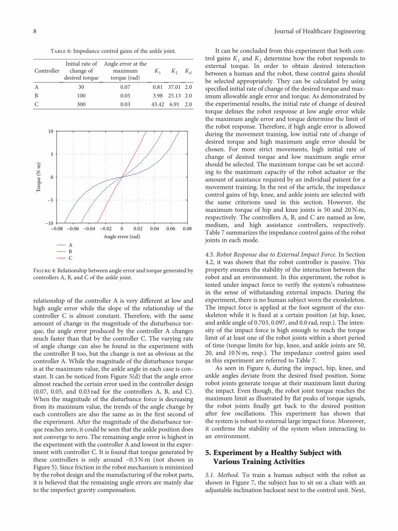
relationship of the controller A is very different at low andhigh angle error while the slope of the relationship of thecontroller C is almost constant. Therefore, with the sameamount of change in the magnitude of the disturbance tor-que, the angle error produced by the controller A changesmuch faster than that by the controller C. The varying rateof angle change can also be found in the experiment withthe controller B too, but the change is not as obvious as thecontroller A. While the magnitude of the disturbance torqueis at the maximum value, the ankle angle in each case is con-stant. It can be noticed from Figure 5(d) that the angle erroralmost reached the certain error used in the controller design(0.07, 0.05, and 0.03 rad for the controllers A, B, and C).When the magnitude of the disturbance force is decreasingfrom its maximum value, the trends of the angle change byeach controllers are also the same as in the first second ofthe experiment. After the magnitude of the disturbance tor-que reaches zero, it could be seen that the ankle position doesnot converge to zero. The remaining angle error is highest inthe experiment with the controller A and lowest in the exper-iment with controller C. It is found that torque generated bythese controllers is only around −0.3N·m (not shown inFigure 5). Since friction in the robot mechanism is minimizedby the robot design and the manufacturing of the robot parts,it is believed that the remaining angle errors are mainly dueto the imperfect gravity compensation.
It can be concluded from this experiment that both con-trol gains K1 and K2 determine how the robot responds toexternal torque. In order to obtain desired interactionbetween a human and the robot, these control gains shouldbe selected appropriately. They can be calculated by usingspecified initial rate of change of the desired torque and max-imum allowable angle error and torque. As demonstrated bythe experimental results, the initial rate of change of desiredtorque defines the robot response at low angle error whilethe maximum angle error and torque determine the limit ofthe robot response. Therefore, if high angle error is allowedduring the movement training, low initial rate of change ofdesired torque and high maximum angle error should bechosen. For more strict movements, high initial rate ofchange of desired torque and low maximum angle errorshould be selected. The maximum torque can be set accord-ing to the maximum capacity of the robot actuator or theamount of assistance required by an individual patient for amovement training. In the rest of the article, the impedancecontrol gains of hip, knee, and ankle joints are selected withthe same criterions used in this section. However, themaximum torque of hip and knee joints is 50 and 20N·m,respectively. The controllers A, B, and C are named as low,medium, and high assistance controllers, respectively.Table 7 summarizes the impedance control gains of the robotjoints in each mode.
4.5. Robot Response due to External Impact Force. In Section4.2, it was shown that the robot controller is passive. Thisproperty ensures the stability of the interaction between therobot and an environment. In this experiment, the robot istested under impact force to verify the system’s robustnessin the sense of withstanding external impacts. During theexperiment, there is no human subject worn the exoskeleton.The impact force is applied at the foot segment of the exo-skeleton while it is fixed at a certain position (at hip, knee,and ankle angle of 0.703, 0.097, and 0.0 rad, resp.). The inten-sity of the impact force is high enough to reach the torquelimit of at least one of the robot joints within a short periodof time (torque limits for hip, knee, and ankle joints are 50,20, and 10N·m, resp.). The impedance control gains usedin this experiment are referred to Table 7.
As seen in Figure 6, during the impact, hip, knee, andankle angles deviate from the desired fixed position. Somerobot joints generate torque at their maximum limit duringthe impact. Even though, the robot joint torque reaches themaximum limit as illustrated by flat peaks of torque signals,the robot joints finally get back to the desired positionafter few oscillations. This experiment has shown thatthe system is robust to external large impact force. Moreover,it confirms the stability of the system when interacting toan environment.
5. Experiment by a Healthy Subject withVarious Training Activities
5.1. Method. To train a human subject with the robot asshown in Figure 7, the subject has to sit on a chair with anadjustable inclination backseat next to the control unit. Next,
Table 6: Impedance control gains of the ankle joint.
ControllerInitial rate ofchange of
desired torque
Angle error at themaximumtorque (rad)
K1 K2 Kd
A 30 0.07 0.81 37.01 2.0
B 100 0.05 3.98 25.13 2.0
C 300 0.03 43.42 6.91 2.0
−0.08 −0.06 −0.04 −0.02 0 0.02 0.04 0.06 0.08−10
−5
0
5
10
Angle error (rad)
Torq
ue (N
. m)
ABC
Figure 4: Relationship between angle error and torque generated bycontrollers A, B, and C of the ankle joint.
8 Journal of Healthcare Engineering

lengths of the exoskeleton segments are adjusted so that therobot fits on the subject’s leg where the axes of hip, knee, andankle joints of the subject are aligned with robot joint axes.Then, Velcro straps are used to fasten the subject’s leg andthe exoskeleton together at thigh, shank, and foot segments.
Before the training session, the reference path must bedefined by teaching the robot. By manually moving the exo-skeleton (and the subject’s leg) to the starting point of thedesired movement, the robot operator can use the user inter-face shown on the monitor screen to record the current jointposition of the robot. The next points of the desired move-ment are also obtained while moving the exoskeleton andrecording a sequence of the desired position. When theteaching is done, the reference path for the training is gener-ated by connecting a series of the selected points with straightlines. The desired joint angles are linearly interpolatedbetween a selected point and the consecutive point. The rep-etition of the path can be selected as moving back and forthor as a cycle (the last point connected to the first point).The desired path can be generated to perform various
0 0.5 1 1.5 2 2.5 3 3.5 40
0.01
0.02
0.03
0.04
0.05
0.06
0.07
0.08
Time (s)
Ank
le an
gle (
rad)
ABC
(a)
ABC
0 0.5 1 1.5 2 2.5 3 3.5 40
0.01
0.02
0.03
0.04
0.05
0.06
0.07
0.08
Time (s)
Ank
le an
gle (
rad)
(b)
ABC
0 0.5 1 1.5 2 2.5 3 3.5 40
0.01
0.02
0.03
0.04
0.05
0.06
0.07
0.08
Time (s)
Ank
le an
gle (
rad)
(c)
ABC
0 0.5 1 1.5 2 2.5 3 3.5 40
0.01
0.02
0.03
0.04
0.05
0.06
0.07
0.08
Time (s)
Ank
le an
gle (
rad)
(d)
Figure 5: Response of robot’s ankle joint implemented with the controllers A, B, and C as a result from the disturbance torque with maximummagnitude of (a) 1.0N·m, (b) 4.0N·m, (c) 7.0N·m, and (d) 10.0N·m.
Table 7: Impedance control gains for hip, knee, and ankle joints inlow, medium, and high assistance mode.
JointLow assistance
modeMedium
assistance modeHigh assistance
modeK1 K2 Kd K1 K2 Kd K1 K2 Kd
Hip 0.44 67.62 5.0 1.38 72.30 5.0 3.20 93.67 5.0
Knee 0.59 50.71 4.0 2.14 46.73 4.0 6.29 47.65 4.0
Ankle 0.81 37.01 2.0 3.98 25.13 2.0 43.42 6.91 2.0
9Journal of Healthcare Engineering

training activities both single-joint and multiple-joint train-ing. Figure 8 presents the reference path of seated marchingexercise (for hip flexion exercise), the single-joint training atknee and ankle joint, and cycling exercise both in joint spaceand Cartesian space. The virtual leg of the subject is illustratedas triangles for thigh (pink), shank (blue), and foot (yellow)segments. It is displayed on the monitor screen as a visualfeedback to the subject while tracking the reference trajectory.
Once the reference trajectory is generated, the operatormust select the trajectory speed and assistance level. Whenthe training starts, the reference position moves from the firstpoint to the last point along the reference path and repeatsthe movement. Actual joint angle and torque are recordedat the frequency of 100Hz and shown on the monitor screen.The training session continues until the “stop” button on theuser interface is pressed.
In this study, a preliminary experiment was conductedon a volunteered healthy subject (male, age 28 years,weight 65 kg, height 168 cm, and without history of
neurological disorder). The training activities include seatedmarching exercise, training at knee and ankle joints, andcycling training whose reference paths are shown inFigure 8. The subject is informed to keep tracking the refer-ence trajectory, which is shown on a monitor screen alongwith the current position of the robot, as much as possible.Speed of the trajectories in Cartesian space is set as a constantthroughout the training. However, for the single-joint train-ing, when reaching the first and the last point of the referencepath, the movement is paused for one second. Each trainingconsists of 8 cycles of movement. Control gains K1, K2, andKd used in this experiment are referred to Table 7.
5.2. Statistical Data Analysis. The data of the movement isseparated into data from each cycle. Time spent on a cycleis normalized so that 0% represents the start of the cycleand 100% is the end of the cycle. Average angle θi%and assistance torque Ti% at i% of a movement cycleare calculated from
θi% =〠n
j=1θji%
n,
Ti% =〠n
j=1Tji%
n,
9
where n is the number of movement cycles which is equal to8 for this experiment, and θji% and T j
i% are angle and torque ati% of the jth cycle. The average data profile is obtained byconnecting average angle from 0% to 100%.
The root mean square value is chosen as the represen-tative of the average data in a movement cycle. The rootmean square error eθre f−θ,rms between the reference
0.80.60.40.2
0
0 1Time (s)
Ang
le (r
ad)
2 3−0.2
604020
0
Torq
ue (N
. m)
−20−40
HipKneeAnkle
0 1Time (s)
2 3
(a)
604020
0
Torq
ue (N
. m)
−20−40
0.80.60.40.2
0
0 1Time (s)
Ang
le (r
ad)
2 3−0.2
0 1Time (s)
2 3
HipKneeAnkle
(b)
604020
0
Torq
ue (N
. m)
−20−40
0.80.60.40.2
0
0 1Time (s)
Ang
le (r
ad)
2 3
0 1Time (s)
2 3
−0.2
HipKneeAnkle
(c)
Figure 6: Response of the robot due to external impact force with control gains for (a) low assistance mode, (b) medium assistancemode, and (c) high assistance mode.
Figure 7: Training a subject with the robot.
10 Journal of Healthcare Engineering

00.2
0.40.6
−0.4−0.2
00.2
−0.1
−0.05
0
0.05
0.1A
nkle
angl
e (ra
d)
Hip angle (rad)Knee angle (rad)
Hip angle (rad)Knee angle (rad)
Hip angle (rad)Knee angle (rad)
Hip angle (rad)Knee angle (rad)
−0.1−0.05
00.05
0.1
−1.5-1
−0.50
−0.1
−0.05
0
0.05
0.1
Ank
le an
gle (
rad)
−0.1−0.05
00.05
0.1
−1−0.8
−0.6−0.4
−0.20
−0.20
0.20.40.60.8
Ank
le an
gle (
rad)
00.2
0.40.6
−0.4−0.2
00.2
−0.1
−0.05
0
0.05
0.1
Ank
le an
gle (
rad)
(a)
−500 −400 −300 −200 −100 0−250
−200
−150
−100
−50
−250
−200
−150
−100
−50
−250
−200
−150
−100
−50
−250
−200
−150
−100
−50
0
50
100
x (pixel)
y (pi
xel)
−500 −400 −300 −200 −100 0
0
50
100
x (pixel)
y (pi
xel)
−500 −400 −300 −200 −100 0
0
50
100
x (pixel)
y (pi
xel)
−500 −400 −300 −200 −100 0
0
50
100
x (pixel)
y (pi
xel)
(b)
Figure 8: Reference paths for seated marching exercise, the single-joint training at knee and ankle joint, and cycling exercise in (a) joint spaceand (b) Cartesian space.
11Journal of Healthcare Engineering

trajectory θref and the average trajectory θ is computedas follows:
eθre f−θ,rms =〠N
k=1 θref ,i% − θi%2
N, 10
where N is the number of data in one cycle of movement(index k = 1 and k =N refers to data at 0% and 100%). Notethat the reference trajectory is the same in every movementcycle, so θref ,i% is not averaged.
To determine the deviation between the trajectory of eachmovement cycle and the average trajectory, another errorthat compares the angle of the jth cycle to the average angleat i% ej
θ−θ,i% is described by
ejθ−θ,i% = θji% − θ
ji% 11
The root mean square error of the jth cycle ejθ−θ,rms is
ejθ−θ,rms =
〠N
k=1 ejθ−θ,i%
2
N12
The standard deviation of the root mean square errorSDeθ−θ,rms
is calculated to identify the variation of data
from 8 movement cycles:
SDeθ−θ,rms=
〠n
j=1 ejθ−θ,rms − eθ−θ,rms
2
n, 13
where
eθ−θ,rms =〠n
j=1ejθ−θ,rms
n14
The root mean square average torque Trms is derivedas follows:
Trms =〠N
k=1 Ti%2
N, 15
where Ti% is the torque averaged from 8 movement cyclesat i%. The root mean square average torque is a good repre-sentation showing the amount of assistance torque providedto a subject because the value of positive and negative sign isnot canceled out. The direction of the assistance torque canbe observed from the average torque profile.
5.3. Results
5.3.1. Seated Marching Exercise. In Figure 9, the average hiptrajectory and torque obtained from 8 movement cyclesand 3 different assistance levels are shown with respect tomovement cycle percentage (0% and 100% represent thestart and the end of each movement cycle). The movementstarts by performing hip flexion (increasing hip angle) andpauses for one second (constant maximum hip angle) andthen performing hip extension (decreasing hip angle) and
pauses for another one second (constant minimum hipangle to complete the cycle). One cycle of the movementtakes 9.45 seconds.
According to Table 8, the training with low assistance hasthe highest angle error. In Figure 9, the average trajectory oflow assistance training has the largest deviation from the ref-erence trajectory while the average trajectory of medium andhigh assistance training is closer to the reference trajectory,respectively. The variation of the actual trajectory in 8movement cycles as compared to the average trajectorycan be identified by the standard deviation. It is noticedfrom Table 8 that the highest variation is found in thetraining with low assistance. Moreover, the average assis-tance torque during the training with low assistance alsohas the lowest magnitude. It can also be seen in Figure 9(b)that the torque profiles in low, medium, and high assistancetraining are similar when compared at each percentage ofthe movement cycle.
5.3.2. Training at Knee Joint. Figure 10 shows the averageknee angle and torque during the training at knee joint.The movement starts by performing knee extension(decreasing knee angle) and pauses for one second (constantminimum knee angle) and then performing knee flexion(increasing knee angle) and ends after another one-secondpause (constant maximum knee angle). Hip and ankle jointsdo not move, so their reference angles are fixed at zero. Onecycle of the movement takes 24.43 seconds.
As shown in Table 9, the low assistance training has thehighest error between the average and the reference trajec-tory. The standard deviation which shows variation of theactual trajectory in 8 movement cycles compared to theaverage trajectory is highest in the low assistance training.Besides, the lowest magnitude of average assistance torqueis found in the low assistance training. As seen fromFigure 10(b), the shapes of torque profiles are similar inlow, medium, and high assistance training.
5.3.3. Training at Ankle Joint. The average ankle angle andtorque during the training are shown in Figure 11. Themovement starts from performing ankle plantar flexion(increasing ankle angle) and pauses for one second andthen performing ankle dorsiflexion (decreasing ankle angle)and pauses for another one second. During the training, theknee angle is fixed at a negative constant angle to avoidthe foot slapping on the floor. One cycle of the movementtakes 6.13 seconds.
According to Table 10, the highest error between theaverage and the reference trajectory is found in the lowassistance training. Large variation of the actual trajectoryin 8 movement cycles compared to the average trajectoryalso occurs in the low assistance training. Moreover, therobot provides the lowest average assistance torque tothe subject in low assistance training. It could be noticedthat the variations of the movement in the medium andhigh assistance are similar. The torque profiles in low,medium, and high assistance as shown in Figure 11(b)are also resemblant.
12 Journal of Healthcare Engineering

5.3.4. Cycling Exercise. In Figure 12, the average angle andassistance torque of hip, knee, and ankle joints are comparedwhen training with low, medium, and high assistance level.As noticed from Figure 13(b), the starting point of the move-ment is located at (x, y) = (−310 pixel, −150 pixel) and thedirection of the movement is counterclockwise around thecenter of the circle located at (x, y) = (−360 pixel, −150 pixel).
The cycling reference trajectory includes the movement ofhip and knee joints while the ankle angle is fixed at zero.The reference trajectory is created from straight lines con-necting reference points to the consecutive points. The move-ment is continuous, so there is no pause in a movement cycle.One cycle of movement takes 11.45 seconds.
As noticed from Table 11, the highest error between theaverage and reference trajectory almost occurs in the trainingwith low assistance. High variation of the movement is alsolikely to be found in the low assistance training comparedto the medium and high assistance training. Furthermore,the average assistance torque applied by the robot is usuallylow in the low assistance training while the medium and highassistance training tend to generate higher magnitude ofassistance torque. It can be seen from Figure 12(b) that theshapes of torque profiles for low, medium, and high assis-tance are similar. Figure 13 compares the average trajectoryto the reference trajectory when the subject trained with
0 20 40 60 80 1000
0.1
0.2
0.3
0.4
0.5
Movement cycle percentage (%)H
ip an
gle (
rad)
0 20 40 60 80 1000
0.1
0.2
0.3
0.4
0.5
Movement cycle percentage (%)
Hip
angl
e (ra
d)
0 20 40 60 80 1000
0.1
0.2
0.3
0.4
0.5
Movement cycle percentage (%)
Hip
angl
e (ra
d)RefLow
RefHigh
RefMed
(a)
0 20 40 60 80 100−6−4−2
02468
10
Movement cycle percentage (%)
Hip
assis
tanc
e tor
que (
N. m
)0 20 40 60 80 100
−6−4−2
02468
10
−6−4−2
02468
10
Movement cycle percentage (%)H
ip as
sista
nce t
orqu
e (N
. m)
0 20 40 60 80 100Movement cycle percentage (%)
Hip
assis
tanc
e tor
que (
N. m
)
(b)
Figure 9: Seated marching exercise with low (Low), medium (Med), and high (High) assistance. (a) Average hip angle compared to thereference trajectory (Ref). (b) Average hip assistance torque.
Table 8: Statistical data of the hip joint from the seated marchingexercise.
Level of assistance eθref−θ,rms (rad)SDeθ−θ,rms
( × 10−4 rad)Trms (N·m)
Low 0.0198 28.31 2.40
Medium 0.0123 11.04 2.57
High 0.0090 6.55 4.25
13Journal of Healthcare Engineering

low, medium, and high assistance. The average trajectories asseen in joint space and Cartesian space are closed to the ref-erence trajectory with some degree of angle error.
5.3.5. Discussion. The experiment has shown that the robot isable to train the subject with many activities and levels ofassistance. The subject can track the reference trajectorieswith some angle errors. The magnitude of the error is usuallyhigh in low assistance training followed by medium and highassistance training.
The variation of the movement can be determined fromthe standard deviation which derived from the comparisonbetween the actual trajectories in 8 movement cycles andthe average trajectory. It was found that the low assistancetraining is likely to have the highest movement variationfor hip, knee, and ankle joints in any training activities. Inother words, the subject has more freedom to move on hisown in the low assistance, even though the patterns of themovement in each cycles are not consistent.
The average magnitude of assistance torque is usuallylowest in the low assistance training. Shapes of the torqueprofiles for low, medium, and high assistance are similarwhen comparing at each movement cycle percentage. Itcould be seen that there are abrupt changes of the torque pro-file in the seated marching exercise and the single-joint train-ing at knee and ankle joints at the transitions before and afterthe movement pauses. These might result from the speed ofthe trajectory which is set as a constant and absence ofsmooth changes at these transitions. Assistance torquechanges rapidly in order to create acceleration/decelerationfor stopping or initiating the movement. These abrupt
0 20 40 60 80 100−1.4−1.2−1
−0.8−0.6−0.4−0.2
0
Movement cycle percentage (%)Kn
ee an
gle (
rad)
Knee
angl
e (ra
d)
−1.4−1.2
−1−0.8−0.6−0.4−0.2
0
−1.4−1.2
−1−0.8−0.6−0.4−0.2
0
Knee
angl
e (ra
d)
0 20 40 60 80 100Movement cycle percentage (%)
RefHigh
0 20 40 60 80 100Movement cycle percentage (%)
(a)
0 20 40 60 80 100−10
−8
−6
−4
−2
02
Movement cycle percentage (%)
Knee
assis
tanc
e tor
que (
N. m
)Kn
ee as
sista
nce t
orqu
e (N
. m)
Knee
assis
tanc
e tor
que (
N. m
)
0 20 40 60 80 100−10
−8
−6
−4
−2
02
Movement cycle percentage (%)
0 20 40 60 80 100−10
−8
−6
−4
−2
0
2
Movement cycle percentage (%)
(b)
Figure 10: Training at knee joint with low (Low), medium (Med), and high (High) assistance. (a) Average knee angle compared to thereference trajectory (Ref). (b) Average knee assistance torque.
Table 9: Statistical data from the training at knee joint.
Level of assistance eθref−θ,rms (rad)SDeθ−θ,rms
( × 10−4 rad)Trms (N·m)
Low 0.0107 23.26 5.35
Medium 0.0077 16.97 5.97
High 0.0033 9.00 6.05
14 Journal of Healthcare Engineering

changes are also found in the cycling exercise when changingthe reference point. Although the speed remains constant,the direction of the movement changes at the referencepoints. Thus, assistance torque changes suddenly in orderto create acceleration for changing the direction of the move-ment at these transitions.
6. Conclusion
Lower limb rehabilitation robots in sitting position have beenresearched extensively. Rehabilitation robots were developed
into many types and targeted at different degrees of freedomfor the physical therapy. Training activities performed bythese robots differ according to robot’s configuration andthe selection of training modalities. These activities can becategorized as single-joint and multiple-joint training. Thesingle-joint training focuses on the movement of an individ-ual joint such as hip, knee, or ankle joint. On the other hand,the multiple-joint training associates the movement of manyjoints in the same time so that a variety of exercises such asleg press, cycling, gait trajectory following, or customizedmovement could be performed. Some robots were developedto perform a specific training activity while the others areable to perform several training activities.
A lower limb rehabilitation robot in sitting position forstroke patients was developed in the previous research. Ithas three degrees of freedom at hip, knee, and ankle jointswhich allow movements of lower limbs in sagittal plane. Thisrobot is able to perform many training activities and modal-ities. The control system for active assistive exercise isdescribed in detail. The impedance control law implemented
0 20 40 60 80 100−0.2
0
0.2
0.4
0.6
0.8
Movement cycle percentage (%)
Ank
le an
gle (
rad)
0 20 40 60 80 100Movement cycle percentage (%)
0 20 40 60 80 100Movement cycle percentage (%)
RefMed
−0.2
0
0.2
0.4
0.6
0.8
Ank
le an
gle (
rad)
−0.2
0
0.2
0.4
0.6
0.8
Ank
le an
gle (
rad)
(a)
0 20 40 60 80 100Movement cycle percentage (%)
0 20 40 60 80 100Movement cycle percentage (%)
0 20 40 60 80 100Movement cycle percentage (%)
−4−3−2−1
01234
Ank
le as
sista
nce t
orqu
e (N
. m)
Ank
le as
sista
nce t
orqu
e (N
. m)
Ank
le as
sista
nce t
orqu
e (N
. m)
−4−3−2−1
01234
−4−3−2−1
01234
(b)
Figure 11: Training at ankle joint with low (Low), medium (Med), and high (High) assistance. (a) Average ankle angle compared to thereference trajectory (Ref). (b) Average ankle assistance torque.
Table 10: Statistical data from the training at ankle joint.
Level ofassistance
eθref−θ,rms(rad)
SDeθ−θ,rms( × 10−4
rad)Trms(N·m)
Low 0.0253 19.56 1.4
Medium 0.0141 4.42 1.81
High 0.0071 5.00 2.15
15Journal of Healthcare Engineering

0 20 40 60 80 1000
0.1
0.2
0.3
0.4
0.5
Movement cycle percentage (%)H
ip an
gle (
rad)
−0.6−0.4−0.2
00.20.40.60.8
Knee
angl
e (ra
d)
−0.01−0.005
00.005
0.010.015
0.020.025
0.03
Ank
le an
gle (
rad)
0 20 40 60 80 100Movement cycle percentage (%)
RefLow
MedHigh
0 20 40 60 80 100Movement cycle percentage (%)
(a)
0 20 40 60 80 100−4−2
02468
101214
Movement cycle percentage (%)
Hip
assis
tanc
e tor
que (
N. m
)
−4−3−2−1
01234
Knee
assis
tanc
e tor
que (
N. m
)
−4−3−2−1
01234
Ank
le as
sista
nce t
orqu
e (N
. m)
0 20 40 60 80 100Movement cycle percentage (%)
0 20 40 60 80 100Movement cycle percentage (%)
LowMedHigh
(b)
Figure 12: Cycling exercise with low (Low), medium (Med), and high (High) assistance. (a) Average hip, knee, and ankle angle compared tothe reference trajectory (Ref). (b) Average hip, knee, and ankle assistance torque.
00.2
0.40.6
−0.4−0.2
00.2
−0.1
−0.05
0
0.05
0.1
Hip angle (rad)Knee angle (rad)
Ank
le an
gle (
rad)
RefLow
MedHigh
(a)
−420 −380 −340 −300 −260−220
−200
−180
−160
−140
−120
−100
−80
−60
x (pixel)
y (pi
xel)
RefLow
MedHigh
(b)
Figure 13: Cycling trajectory compared to the reference trajectory (Ref) with low (Low), medium (Med), and high (High) assistance in(a) joint space and (b) Cartesian space.
16 Journal of Healthcare Engineering

by the developed rehabilitation robot uses two constants todefine the relationship between angle error and desired tor-que to be generated by a robot joint. With the damping termin the impedance control law, the passivity property of thesystem is verified. These control gains are chosen based onthe initial rate of change of desired torque, maximum allow-able angle error and torque. Different sets of control gainsresult in different robot response due to disturbance torque.The robot is also tested under impact force to prove itsrobustness. The experiment conducted on a healthy subjecthas shown that the robot is able to perform many trainingactivities such as seated marching exercise, single-joint train-ing at knee and ankle joints, and cycling exercise with activeassistive training modality and with many levels of assistance.It is found that low assistance training usually produces thehighest error between the average trajectory and the refer-ence trajectory. This implies that the subject is not restrictedto move exactly along the reference trajectory. The standarddeviation is derived by comparing the movement in eachcycle to the average trajectory so that the variation of themovement could be investigated. The greatest movementvariation is likely to be found in low assistance training thanin medium and high assistance training. High angle deviationand movement variation in low assistance training implythat the subject could move the limbs with more freedom.The assistance torque is provided by the robot to ensurethe completion of the movement. It is also found thatthe low assistance training usually generates the lowestmagnitude of the assistance torque. Abrupt changes inassistance torque, which can be noticed in each trainingactivity, result from the rapid change in speed and direc-tion of the reference trajectory.
In future research, the movement of the robot at thetransitions should be improved by smoothing the change inspeed and direction at the transitions. Clinical trials shouldbe conducted on stroke patients to verify the effectivenessof the robot and control system for stroke rehabilitation task.
Conflicts of Interest
The authors declare that there is no conflict of interestregarding the publication of this paper.
Acknowledgments
This research work is a part of the project supported by theNational Research University Project, Office of HigherEducation Commission, Project nos. WCU-013-HR-57 andCU-59-005-IC and also supported by the Research Pyramid
and Chula Research Scholar project, the Second CenturyResearch Policy of Chulalongkorn University, 2016–2018,and the 100th Anniversary Chulalongkorn University Fundfor Doctoral Scholarship.
References
[1] G. Colombo, M. Joerg, R. Schreier, and V. Dietz, “Treadmilltraining of paraplegic patients using a robotic orthosis,” Jour-nal of Rehabilitation Research and Development, vol. 37,no. 6, pp. 693–700, 2000.
[2] E. Akdogan and M. A. Adli, “The design and control of a ther-apeutic exercise robot for lower limb rehabilitation: Phy-siotherabot,” Mechatronics, vol. 21, no. 3, pp. 509–522, 2011.
[3] W. Meng, Q. Liu, Z. Zhou, Q. Ai, B. Sheng, and S. Xie, “Recentdevelopment of mechanisms and control strategies for robot-assisted lower limb rehabilitation,” Mechatronics, vol. 31,pp. 132–145, 2015.
[4] I. Díaz, J. J. Gil, and E. Sánchez, “Lower-limb robotic rehabili-tation: literature review and challenges,” Journal of Robotics,vol. 2011, 11 pages, 2011.
[5] B. Guo, J. Han, X. Li, T. Fang, and A. You, “Research anddesign of a new horizontal lower limb rehabilitation trainingrobot,” International Journal of Advanced Robotic Systems,vol. 13, no. 1, pp. 10–10, 2016.
[6] J. A. Galvez, A. Budovitch, S. J. Harkema, and D. J. Reinkens-meyer, “Trainer variability during step training after spinalcord injury: implications for robotic gait-training devicedesign,” The Journal of Rehabilitation Research and Develop-ment, vol. 48, no. 2, pp. 147–160, 2011.
[7] J. Yoon, J. Ryu, and K.-B. Lim, “Reconfigurable ankle rehabil-itation robot for various exercises,” Journal of Robotic Systems,vol. 22, no. S1, pp. S15–S33, 2006.
[8] F. Zhang, Z. G. Hou, L. Cheng et al., “iLeg—a lower limb reha-bilitation robot: a proof of concept,” IEEE Transactions onHuman-Machine Systems, vol. 46, no. 5, pp. 761–768, 2016.
[9] T. B. Pasqual, G. A. P. Caurin, and A. A. G. Siqueira, “Seriousgame development for ankle rehabilitation aiming at userexperience,” in 2016 6th IEEE International Conference on Bio-medical Robotics and Biomechatronics (BioRob), Singapore,June 2016.
[10] A. Mirelman, B. L. Patritti, P. Bonato, and J. E. Deutsch,“Effects of virtual reality training on gait biomechanics of indi-viduals post-stroke,” Gait & Posture, vol. 31, no. 4, pp. 433–437, 2010.
[11] W. Wang, Z. G. Hou, L. Tong, F. Zhang, Y. Chen, and M. Tan,“A novel leg orthosis for lower limb rehabilitation robots of thesitting/lying type,” Mechanism and Machine Theory, vol. 74,pp. 337–353, 2014.
[12] A. B. Farjadian, M. Nabian, C. Mavroidis, and M. K. Holden,“Implementation of a task-dependent anisotropic impedance
Table 11: Statistical data from the cycling training.
Statistical dataLow assistance Medium assistance High assistance
eθref−θ,rms(rad)
SDeθ−θ,rms
( × 10−4 rad)Trms(N·m)
eθref−θ,rms(rad)
SDeθ−θ,rms
( × 10−4 rad)Trms(N·m)
eθref−θ,rms(rad)
SDeθ−θ,rms
( × 10−4 rad)Trms(N·m)
Hip 0.0125 25.31 3.50 0.0104 8.76 3.82 0.0041 9.14 4.11
Knee 0.0199 29.76 1.91 0.0150 6.91 1.50 0.0073 2.82 1.02
Ankle 0.0090 13.09 0.52 0.0100 1.29 1.31 0.0030 2.82 1.08
17Journal of Healthcare Engineering

controller into a 2-DOF platform-based ankle rehabilitationrobot,” in 2015 IEEE International Conference on Roboticsand Automation (ICRA), Seattle, WA, USA, May 2015.
[13] D. A. Brown, S. Nagpal, and S. Chi, “Limb-loaded cycling pro-gram for locomotor intervention following stroke,” PhysicalTherapy, vol. 85, no. 2, pp. 159–168, 2005.
[14] J. C. Grotta, G. W. Albers, J. P. Broderick et al., Stroke: Patho-physiology, Diagnosis, and Management, Elsevier, China, 6thedition, 2016.
[15] A. Basteris, S. M. Nijenhuis, A. H. A. Stienen, J. H. Buurke,G. B. Prange, and F. Amirabdollahian, “Training modalitiesin robot-mediated upper limb rehabilitation in stroke: a frame-work for classification based on a systematic review,” Journalof Neuroengineering and Rehabilitation, vol. 11, no. 1,pp. 111–115, 2014.
[16] H. I. Krebs, J. J. Palazzolo, L. Dipietro et al., “Rehabilitationrobotics: performance-based progressive robot-assisted ther-apy,” Autonomous Robots, vol. 15, no. 1, pp. 7–20, 2003.
[17] H. M. Clarkson,Musculoskeletal Assessment: Joint Motion andMuscle Testing, Wolters Kluwer/Lippincott Williams & Wil-kins Health, China, 3rd edition, 2013.
[18] T. Eiammanussakul and V. Sangveraphunsiri, “Lower limbrehabilitation robot in sitting position for various therapeuticexercises,” in 2017 in Proceedings of the 9th International Con-ference on Bioinformatics and Biomedical Technology - ICBBT'17, pp. 112–116, Lisbon, Portugal, May 2017.
[19] A. Roy, H. I. Krebs, D. J. Williams et al., “Robot-aided neu-rorehabilitation: a novel robot for ankle rehabilitation,”IEEE Transactions on Robotics, vol. 25, no. 3, pp. 569–582,2009.
[20] F. Chrif, T. Nef, M. Lungarella, R. Dravid, and K. J. Hunt,“Control design for a lower-limb paediatric therapy deviceusing linear motor technology,” Biomedical Signal Processingand Control, vol. 38, pp. 119–127, 2017.
[21] K. J. Chisholm, K. Klumper, A. Mullins, and M. Ahmadi, “Atask oriented haptic gait rehabilitation robot,” Mechatronics,vol. 24, no. 8, pp. 1083–1091, 2014.
[22] A. Kamps and K. Schüle, “Cyclic movement training of thelower limb in stroke rehabilitation,” Neurologie & Rehabilita-tion, vol. 11, no. 5, pp. S1–S12, 2005.
[23] R. N. Goodman, J. C. Rietschel, A. Roy et al., “Increased rewardin ankle robotics training enhances motor control and corticalefficiency in stroke,” Journal of Rehabilitation Research andDevelopment, vol. 51, no. 2, pp. 213–228, 2014.
[24] L. W. Forrester, A. Roy, H. I. Krebs, and R. F. Macko, “Ankletraining with a robotic device improves hemiparetic gait aftera stroke,” Neurorehabilitation and Neural Repair, vol. 25,no. 4, pp. 369–377, 2011.
[25] A. Roy, L. W. Forrester, and R. F. Macko, “Short-term anklemotor performance with ankle robotics training in chronichemiparetic stroke,” The Journal of Rehabilitation Researchand Development, vol. 48, no. 4, pp. 417–429, 2011.
[26] E. Badics, A. Wittmann, M. Rupp, B. Stabauer, and U. A.Zifko, “Systematic muscle building exercises in the rehabilita-tion of stroke patients,” NeuroRehabilitation, vol. 17, no. 3,pp. 211–214, 2002.
[27] J. Vinstrup, J. Calatayud, M. D. Jakobsen et al., “Electromyo-graphic comparison of conventional machine strength train-ing versus bodyweight exercises in patients with chronicstroke,” Topics in Stroke Rehabilitation, vol. 24, no. 4,pp. 242–249, 2016.
[28] S. M. Son, M. K. Park, and N. K. Lee, “Influence of resistanceexercise training to strengthen muscles across multiple jointsof the lower limbs on dynamic balance functions of strokepatients,” Journal of Physical Therapy Science, vol. 26, no. 8,pp. 1267–1269, 2014.
[29] R. Fernandez-Gonzalo, C. Nissemark, B. Åslund, P. A. Tesch,and P. Sojka, “Chronic stroke patients show early and robustimprovements in muscle and functional performance inresponse to eccentric-overload flywheel resistance training: apilot study,” Journal of Neuroengineering and Rehabilitation,vol. 11, no. 1, pp. 150–110, 2014.
[30] S. J. Kim, H. Y. Cho, Y. L. Kim, and S. M. Lee, “Effects of sta-tionary cycling exercise on the balance and gait abilities ofchronic stroke patients,” Journal of Physical Therapy Science,vol. 27, no. 11, pp. 3529–3531, 2015.
[31] D. Barbosa, C. P. Santos, and M. Martins, “The application ofcycling and cycling combined with feedback in the rehabilita-tion of stroke patients: a review,” Journal of Stroke and Cere-brovascular Diseases, vol. 24, no. 2, pp. 253–273, 2015.
[32] D. A. Winter, Biomechanics and Motor Control of HumanMovement, John Wiley & Sons Inc, USA, 4th edition, 2009.
[33] A. Sutapun and V. Sangveraphunsiri, “A 4-DOF upper limbexoskeleton for stroke rehabilitation: kinematics mechanicsand control,” International Journal of Mechanical Engineeringand Robotics Research, vol. 4, no. 3, pp. 269–272, 2015.
[34] M. D. Lewek, T. H. Cruz, J. L. Moore, H. R. Roth, Y. Y. Dhaher,and T. G. Hornby, “Allowing intralimb kinematic variabilityduring locomotor training poststroke improves kinematicconsistency: a subgroup analysis from a randomized clinicaltrial,” Physical Therapy, vol. 89, no. 8, pp. 829–839, 2009.
[35] A. Duschau-Wicke, J. von Zitzewitz, A. Caprez,L. Lünenburger, and R. Riener, “Path control: a method forpatient-cooperative robot-aided gait rehabilitation,” IEEETransactions on Neural Systems and Rehabilitation Engineer-ing, vol. 18, no. 1, pp. 38–48, 2010.
[36] A. Pennycott, D. Wyss, H. Vallery, V. Klamroth-Marganska,and R. Riener, “Towards more effective robotic gait trainingfor stroke rehabilitation: a review,” Journal of Neuroengineer-ing and Rehabilitation, vol. 9, no. 1, p. 65, 2012.
[37] B. M. Fleerkotte, B. Koopman, J. H. Buurke, E. H. F. van Assel-donk, H. van der Kooij, and J. S. Rietman, “The effect ofimpedance-controlled robotic gait training on walking abilityand quality in individuals with chronic incomplete spinal cordinjury: an explorative study,” Journal of Neuroengineering andRehabilitation, vol. 11, no. 1, p. 26, 2014.
[38] S. K. Banala, S. K. Agrawal, and J. P. Scholz, “Active leg exo-skeleton (ALEX) for gait rehabilitation of motor-impairedpatients,” in 2007 IEEE International Conference on Rehabili-tation Robotics, pp. 401–407, Noordwijk, Netherlands, June2007.
[39] X. Jin, X. Cui, and S. K. Agrawal, “Design of a cable-drivenactive leg exoskeleton (C-ALEX) and gait training experimentswith human subjects,” in 2015 IEEE International Conferenceon Robotics and Automation (ICRA), pp. 5578–5583, Seattle,WA, USA, May 2015.
[40] J. J. E. Slotine and W. Li, Applied Nonlinear Control, Prentice-Hall Inc., USA, 1st edition, 1991.
18 Journal of Healthcare Engineering

International Journal of
AerospaceEngineeringHindawiwww.hindawi.com Volume 2018
RoboticsJournal of
Hindawiwww.hindawi.com Volume 2018
Hindawiwww.hindawi.com Volume 2018
Active and Passive Electronic Components
VLSI Design
Hindawiwww.hindawi.com Volume 2018
Hindawiwww.hindawi.com Volume 2018
Shock and Vibration
Hindawiwww.hindawi.com Volume 2018
Civil EngineeringAdvances in
Acoustics and VibrationAdvances in
Hindawiwww.hindawi.com Volume 2018
Hindawiwww.hindawi.com Volume 2018
Electrical and Computer Engineering
Journal of
Advances inOptoElectronics
Hindawiwww.hindawi.com
Volume 2018
Hindawi Publishing Corporation http://www.hindawi.com Volume 2013Hindawiwww.hindawi.com
The Scientific World Journal
Volume 2018
Control Scienceand Engineering
Journal of
Hindawiwww.hindawi.com Volume 2018
Hindawiwww.hindawi.com
Journal ofEngineeringVolume 2018
SensorsJournal of
Hindawiwww.hindawi.com Volume 2018
International Journal of
RotatingMachinery
Hindawiwww.hindawi.com Volume 2018
Modelling &Simulationin EngineeringHindawiwww.hindawi.com Volume 2018
Hindawiwww.hindawi.com Volume 2018
Chemical EngineeringInternational Journal of Antennas and
Propagation
International Journal of
Hindawiwww.hindawi.com Volume 2018
Hindawiwww.hindawi.com Volume 2018
Navigation and Observation
International Journal of
Hindawi
www.hindawi.com Volume 2018
Advances in
Multimedia
Submit your manuscripts atwww.hindawi.com


![A Lower Limb Rehabilitation Robot in Sitting Position with ...downloads.hindawi.com/journals/jhe/2018/1927807.pdf · ties while Vi-RABT [12] can train ankle joint with active assistive](https://img.pdfslide.us/doc/110x75/5ea36437b1eaa047142ed29a/a-lower-limb-rehabilitation-robot-in-sitting-position-with-ties-while-vi-rabt.jpg)