Embed Size (px)
Citation preview
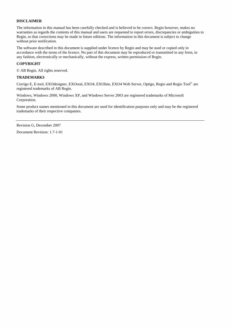
Corrigo E - User ManualVentilation
DISCLAIMER
The information in this manual has been carefully checked and is believed to be correct. Regin however, makes no warranties as regards the contents of this manual and users are requested to report errors, discrepancies or ambiguities to Regin, so that corrections may be made in future editions. The information in this document is subject to change without prior notification.
The software described in this document is supplied under licence by Regin and may be used or copied only in accordance with the terms of the licence. No part of this document may be reproduced or transmitted in any form, in any fashion, electronically or mechanically, without the express, written permission of Regin.
COPYRIGHT
© AB Regin. All rights reserved.
TRADEMARKS
Corrigo E, E-tool, EXOdesigner, EXOreal, EXO4, EXOline, EXO4 Web Server, Optigo, Regio and Regio Tool© are registered trademarks of AB Regin.
Windows, Windows 2000, Windows XP, and Windows Server 2003 are registered trademarks of Microsoft Corporation.
Some product names mentioned in this document are used for identification purposes only and may be the registered trademarks of their respective companies.
Revision G, December 2007
Document Revision: 1.7-1-01
Table of contents
Chapter 1 About the manual 4
Chapter 2 About Corrigo E 5
Chapter 3 Installation and wiring 8
Chapter 4 Commissioning 15
Chapter 5 Functional description 17
Chapter 6 Starting and stopping the unit 34
Chapter 7 Display, LEDs and buttons 36
Chapter 8 Access rights 38
Chapter 9 Configuration 40
Chapter 10 Settings 58
Chapter 11 Scheduler 62
Chapter 12 Setpoint 64
Chapter 13 Manual / Auto 68
Chapter 14 In- / Outputs 70
Chapter 15 Other functions 71
Chapter 16 Index 72
Corrigo E Ventilation manual, revision G Chapter 1 About the manual 4
Chapter 1 About the manual
This manual covers all the models in the Corrigo E series of ventilation controllers. This revision covers program revision 1.7-1-01.
More information More information about Corrigo E can be found in:
• Manual E-tool – Manual of how to configure the controllers
• Lon-interface variable list – Variable list for the Corrigo E series
• Network variables for EXOline and Modbus – Variable list for EXOline and Modbus communication
• CE - Declaration of conformity, Corrigo E
The information is available for download from Regin’s homepage, www.regin.se.
Corrigo E Ventilation manual, revision G Chapter 2 About Corrigo E 5
Chapter 2 About Corrigo E
Corrigo E for ventilation is a complete new range of programmable controllers for control of building facility systems as air handling units.
Corrigo E series for ventilation comprises three model sizes: 8, 15 or 28 in-/outputs. Available with or without front panel display and buttons. For units without front panel display and buttons a separate, cable-connected terminal E-DSP with display and buttons is available.
All programming and normal handling can be done using the display and buttons or from a connected computer running Corrigo E-tool and using EXOline for communication.
The temperature controller is based on a supply air PI-controller for heating control with a pre-programmed set of control modes. To this controller can be bound a number of different control functions and analogue and digital input and output functions. The choice of which functions are to be used is free, the only restriction lying in the physical number of inputs and outputs that the different models have.
The Corrigo is designed for DIN-rail mounting.
The program for an air handling unit contains, apart from other things, the following functions:
Different temperature control modes Supply air temperature control, with or without outdoor temperature compensation
Room temperature control (cascade controller)
Exhaust air temperature control (cascade controller).
With control of: Heat exchanger (Liquid connected- , plate- or rotating) or mixing dampers.
Heater battery; Water with frost protection or electric.
Chiller
Supply air and exhaust air fans (single-speed, two-speed, pressure controlled or flow controlled).
Fire dampers.
Circulation pumps heating, cooling, exchanger.
Humidity control Either Humidification or Dehumidification or both Humidification and Dehumidification.
Timer control For starting and stopping the unit.
Demand controlled ventilation In buildings with strongly varying occupancy the fan speeds or mixing dampers can be controlled by the air quality measured by a CO2/VOC sensor.
Support control When using the control function Room control or exhaust air temperature control with a room sensor connected it is possible to utilise support-heating and/or support-cooling. Minimum running time is settable 0…720 minutes (factory setting 20 minutes).
Corrigo E Ventilation manual, revision G Chapter 2 About Corrigo E 6
Free cooling The function is used during the summer to cool the building during the night using cool outdoor air thereby reducing the need to run chillers during the day.
Step controllers Heating/Cooling As an alternative to the analogue control of ”Actuator heating Y1” or ”Actuator cooling Y3” step controllers can be used for controlling heating or cooling in steps using digital control.
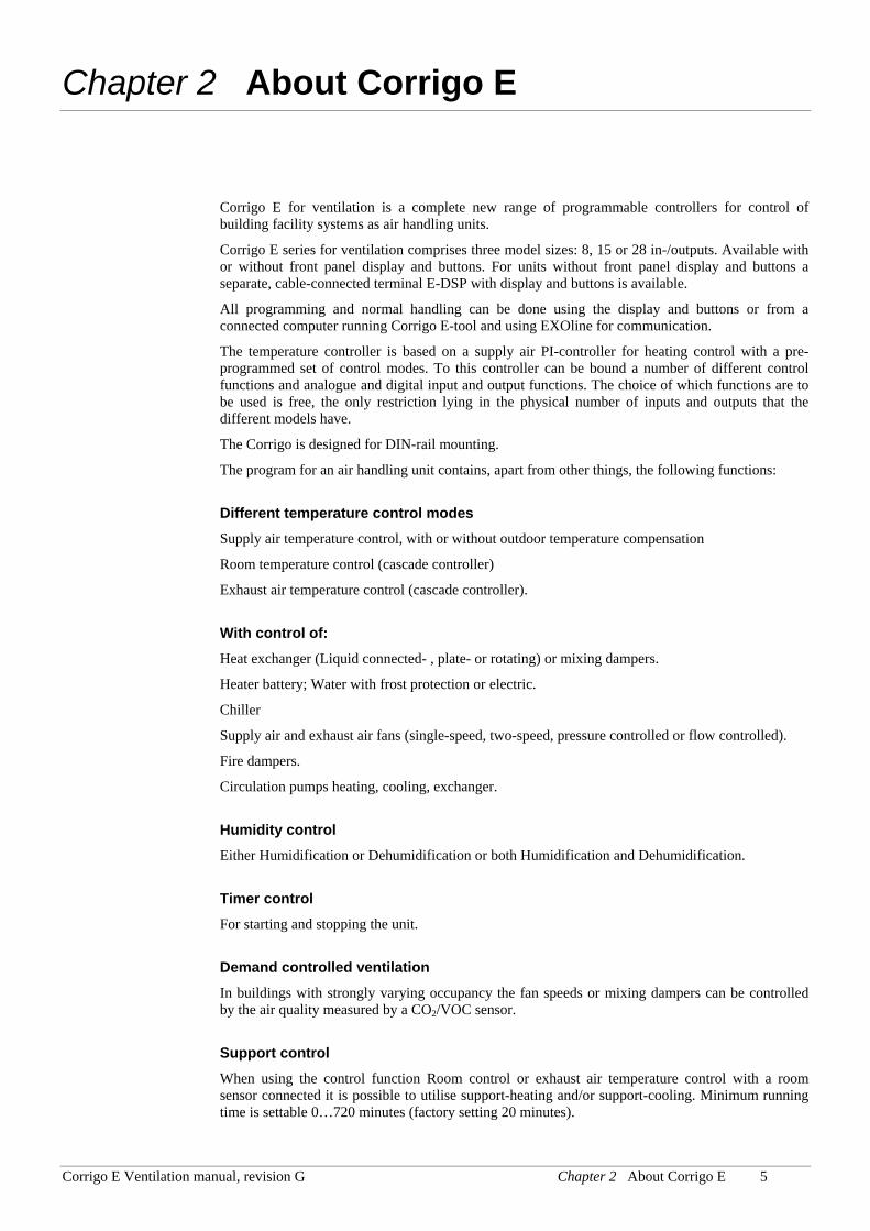
Corrigo E hardware overview
Model 8 8D 15 15D 28 28D
Analogue Inputs 2 2 4 4 4 4 Digital Inputs 3 3 4 4 8 8 Universal Inputs - - - - 4 4 Analogue Outputs 1 1 3 3 5 5 Digital Outputs 2 2 4 4 7 7 RS485 Yes Yes Yes Yes Yes Yes LON Option Option Option Option Option Option TCP/IP Option Option Option Option Option Option Display No Yes No Yes Nej Yes Ext. display Option No Option No Option No
Technical data Protection class .................................................................................................................. IP20 Display........................................................4 rows of 20 characters. Background illumination. LEDs Yellow .......................................................................................................Settable parameter Red.................................................................................................................................Alarm Clock ..................................................................Year base 24 hour clock with battery backup. Automatic summer-/winter-time changeover. Operating system..........................................................................................................EXOreal Supply voltage ...................................................................................................24 V AC, 6 VA Dimensions .................................................................... 148x123x60 (WxHxD incl. terminals) Casing......................................................................................................... Standard Euronorm Mounting ................................................................................................................ On DIN-rail Operation Climatic conditions according to IEC 721-3-3 ........................................................ Class 3k5 Ambient temperature ................................................................................................. 0...50°C Ambient humidity..............................................................................................Max 95% RH Mechanical requirements according to IEC721-3-3 ..............................................Class 3M3 Vibration.......................................................... IEC60068-2-6, Test FC, vibration Sinusoidal Shock ................................................................................................IEC60068-2-27, Test Ea Transport Climatic conditions according to IEC 721-3-2 ........................................................ Class 2k3 Ambient temperature .............................................................................................. -20...70°C Air humidity ......................................................................................................Max 95% RH Mechanical requirements according to IEC721-3-2 ..............................................Class 2M2 Vibration.......................................................... IEC60068-2-6, Test FC, vibration Sinusoidal Shock ................................................................................................IEC60068-2-27, Test Ea Free fall............................................................................................ IEC60068-2-27, Test Ed Storage Climatic conditions according to IEC 721-3-1 ........................................................ Class 1k3 Ambient temperature .............................................................................................. -20...70°C Air humidity ......................................................................................................Max 95% RH
Corrigo E Ventilation manual, revision G Chapter 2 About Corrigo E 7
Battery Type....................................................................................................Replaceable Lithium cell Battery life ....................................................................................................Better than 5 years Warning .................................................................................................... Low battery warning Battery backup...............................................................................Memory and real time clock
Communication EXOline Port 1, insulated via a built-in RS485 contact. The basic version of Corrigo E can communicate with Modbus. You do not need an activation code. Corrigo E can be ordered with a communication port for TCP/IP or LON.
CE-marking Conforms with the EMC standards: CENELEC EN61000-6-3:2001, CENELEC EN61000-6-1:2001.
Inputs Analogue inputs AI..............................................Settable 0…10 V DC or PT1000, 12 bit A/D Digital inputs DI .......................................................................................Potential free closure Universal inputs UI...........................................Can be set to act as either an analogue input or a digital input with specifications as above Outputs Analogue outputs AO....................................................... Settable 0…10 V DC; 2…10 V DC; 10…0 V DC or 10…2 V DC 8 bit D/A short-circuit protected Digital outputs DO .................................................. Triac outputs, 24 V AC, 0.5 A continuous Options LON................................................................... FT3150, gives a second communication route TCP/IP ..................................................Replaces RS485 for EXOline (Port 1) communication External hand terminal, E-DSP ...........................For use with Corrigo E units without display
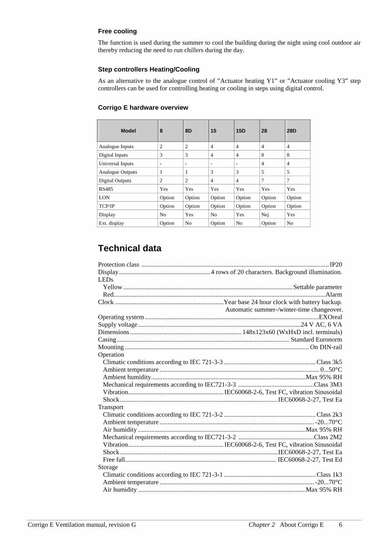
Position of the terminals on Corrigo E
Corrigo E Ventilation manual, revision G Chapter 3 Installation and wiring 8
Chapter 3 Installation and wiring
3.1 Installation Corrigo E can be mounted in a DIN-standard casing (minimum 9 modules), on a DIN-rail in a cabinet or, using a suitable front-mounting kit, in a cabinet door or other control panel.
Ambient temperature: 0…50°C.
Ambient humidity: max. 95 %RH, non-condensing.
3.2 Wiring At the end of this chapter there are wiring diagrams showing the factory set configuration. We have also included blank diagrams. Since the function of most of the inputs and outputs depends on the programming of the unit the final wiring diagram cannot be filled in until the installer has decided how to use the inputs/outputs. It is important to make sure that the wiring is correctly done and in accordance with the instructions given in this manual.
3.2.1 Supply voltage 24 V AC ±15%, 50/60 Hz. 6 VA
If the Corrigo E and the actuators connected to it share the same transformer it is essential that the same transformer-pole is used as reference for all the equipment. Failure to do so will prevent the equipment from functioning as intended and may also lead to damages.
3.2.2 Inputs and outputs The list of input and output functions in section 3.2.3 is a handy instrument to help you keep track of which inputs and outputs you will need to configure.
Analogue inputs Analogue inputs must refer to an A-gnd terminal placed in the same terminal block as the input being wired.
Analogue inputs can, depending on the configuration, be used for either PT1000 temperature sensors or for 0…10 V DC analogue input signals, for example from a pressure transmitter.
Digital inputs Digital inputs must refer to C+ on terminal 4. Digital inputs may only be wired to voltage-free contacts. Any external voltage applied to a digital input may harm the unit.
Universal inputs A universal input can be configured to act as either an analogue input or as a digital input.
A universal inputs configured as an analogue input can, depending on the configuration, be used for either PT1000 temperature sensors or for 0…10 V DC analogue input signals, for example from a pressure transmitter.
Universal inputs configured as an analogue input must refer to an A-gnd terminal placed in the same terminal block as the input being wired.
A universal input configured as a digital input must, just like other digital inputs refer to C+ on terminal 4. It may only be wired to voltage-free contacts.
Corrigo E Ventilation manual, revision G Chapter 3 Installation and wiring 9
Analogue outputs Analogue outputs must refer to the A-gnd terminal placed in the AO terminal block.
All analogue outputs can be individually set to any one of the following signals:
0…10 V DC
2…10 V DC
10…0 V DC
10…2 V DC
If the Corrigo E and the actuators connected to it share the same transformer it is essential that the same transformer-pole is used as reference for all the equipment. Failure to do so will prevent the equipment from functioning as intended and may also lead to damages.
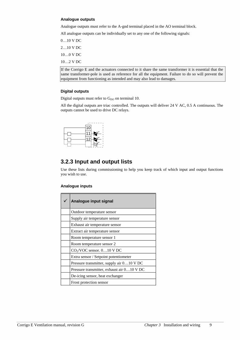
Digital outputs Digital outputs must refer to GDO on terminal 10.
All the digital outputs are triac controlled. The outputs will deliver 24 V AC, 0.5 A continuous. The outputs cannot be used to drive DC relays.
101112
3.2.3 Input and output lists Use these lists during commissioning to help you keep track of which input and output functions you wish to use.
Analogue inputs
Analogue input signal
Outdoor temperature sensor Supply air temperature sensor Exhaust air temperature sensor Extract air temperature sensor Room temperature sensor 1 Room temperature sensor 2 CO2/VOC sensor. 0…10 V DC Extra sensor / Setpoint potentiometer Pressure transmitter, supply air 0…10 V DC Pressure transmitter, exhaust air 0…10 V DC De-icing sensor, heat exchanger Frost protection sensor
Corrigo E Ventilation manual, revision G Chapter 3 Installation and wiring 10
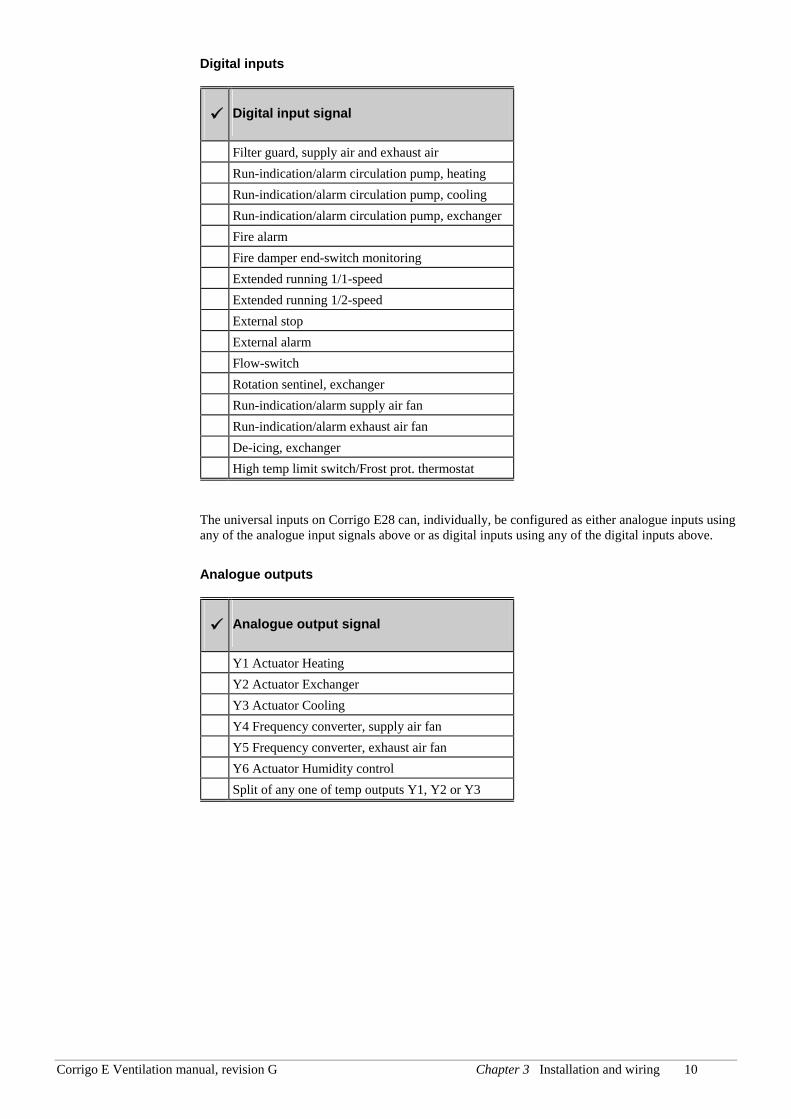
Digital inputs
Digital input signal
Filter guard, supply air and exhaust air Run-indication/alarm circulation pump, heating Run-indication/alarm circulation pump, cooling Run-indication/alarm circulation pump, exchanger Fire alarm Fire damper end-switch monitoring Extended running 1/1-speed Extended running 1/2-speed External stop External alarm Flow-switch Rotation sentinel, exchanger Run-indication/alarm supply air fan Run-indication/alarm exhaust air fan De-icing, exchanger High temp limit switch/Frost prot. thermostat
The universal inputs on Corrigo E28 can, individually, be configured as either analogue inputs using any of the analogue input signals above or as digital inputs using any of the digital inputs above.
Analogue outputs
Analogue output signal
Y1 Actuator Heating Y2 Actuator Exchanger Y3 Actuator Cooling Y4 Frequency converter, supply air fan Y5 Frequency converter, exhaust air fan Y6 Actuator Humidity control Split of any one of temp outputs Y1, Y2 or Y3
Corrigo E Ventilation manual, revision G Chapter 3 Installation and wiring 11
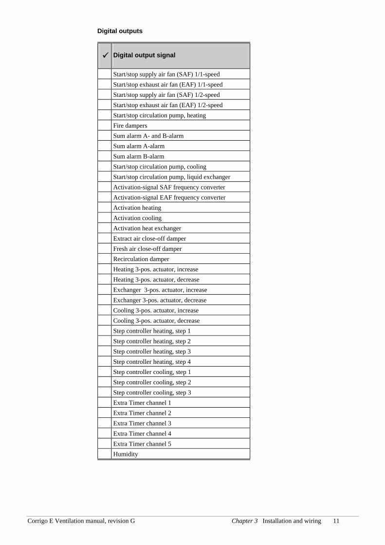
Digital outputs
Digital output signal
Start/stop supply air fan (SAF) 1/1-speed Start/stop exhaust air fan (EAF) 1/1-speed Start/stop supply air fan (SAF) 1/2-speed Start/stop exhaust air fan (EAF) 1/2-speed Start/stop circulation pump, heating Fire dampers Sum alarm A- and B-alarm Sum alarm A-alarm Sum alarm B-alarm Start/stop circulation pump, cooling Start/stop circulation pump, liquid exchanger Activation-signal SAF frequency converter Activation-signal EAF frequency converter Activation heating Activation cooling Activation heat exchanger Extract air close-off damper Fresh air close-off damper Recirculation damper Heating 3-pos. actuator, increase Heating 3-pos. actuator, decrease Exchanger 3-pos. actuator, increase Exchanger 3-pos. actuator, decrease Cooling 3-pos. actuator, increase Cooling 3-pos. actuator, decrease Step controller heating, step 1 Step controller heating, step 2 Step controller heating, step 3 Step controller heating, step 4 Step controller cooling, step 1 Step controller cooling, step 2 Step controller cooling, step 3 Extra Timer channel 1 Extra Timer channel 2 Extra Timer channel 3 Extra Timer channel 4 Extra Timer channel 5 Humidity
Corrigo E Ventilation manual, revision G Chapter 1 12
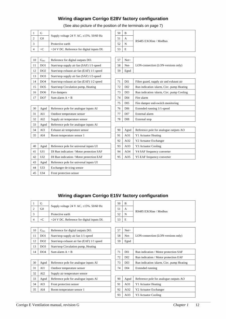
Wiring diagram Corrigo E28V factory configuration (See also picture of the position of the terminals on page 7)
1 G 50 B
2 G0 Supply voltage 24 V AC, ±15%. 50/60 Hz
51 A
3 Protective earth 52 N
4 +C +24 V DC. Reference for digital inputs DI. 53 E
RS485 EXOline / Modbus
10 GDO Reference for digital outputs DO. 57 Net+
11 DO1 Start/stop supply air fan (SAF) 1/1-speed 58 Net-
12 DO2 Start/stop exhaust air fan (EAF) 1/1 speed 59 Egnd
LON-connection (LON-versions only)
13 DO3 Start/stop supply air fan (SAF) 1/2-speed
14 DO4 Start/stop exhaust air fan (EAF) 1/2 speed 71 DI1 Filter guard, supply air and exhaust air
15 DO5 Start/stop Circulation pump, Heating 72 DI2 Run indication /alarm, Circ. pump Heating
16 DO6 Fire dampers 73 DI3 Run indication /alarm, Circ. pump Cooling
17 DO7 Sum alarm A + B 74 DI4 Fire alarm
75 DI5 Fire damper end-switch monitoring
30 Agnd Reference pole for analogue inputs AI 76 DI6 Extended running 1/1-speed
31 AI1 Outdoor temperature sensor 77 DI7 External alarm
32 AI2 Supply air temperature sensor 78 DI8 External stop
33 Agnd Reference pole for analogue inputs AI
34 AI3 Exhaust air temperature sensor 90 Agnd Reference pole for analogue outputs AO
35 AI4 Room temperature sensor 1 91 AO1 Y1 Actuator Heating
92 AO2 Y2 Actuator Exchanger
40 Agnd Reference pole for universal inputs UI 93 AO3 Y3 Actuator Cooling
41 UI1 DI Run indication / Motor protection SAF 94 AO4 Y4 SAF frequency converter
42 UI2 DI Run indication / Motor protection EAF 95 AO5 Y5 EAF frequency converter
43 Agnd Reference pole for universal inputs UI
44 UI3 Exchanger de-icing sensor
45 UI4 Frost protection sensor
Wiring diagram Corrigo E15V factory configuration 1 G 50 B
2 G0 Supply voltage 24 V AC, ±15%. 50/60 Hz
51 A
3 Protective earth 52 N
4 +C +24 V DC. Reference for digital inputs DI. 53 E
RS485 EXOline / Modbus
10 GDO Reference for digital outputs DO. 57 Net+
11 DO1 Start/stop supply air fan 1/1-speed 58 Net-
12 DO2 Start/stop exhaust air fan (EAF) 1/1 speed 59 Egnd
LON-connection (LON-versions only)
13 DO3 Start/stop Circulation pump, Heating
14 DO4 Sum alarm A + B 71 DI1 Run indication / Motor protection SAF
72 DI2 Run indication / Motor protection EAF
30 Agnd Reference pole for analogue inputs AI 73 DI3 Run indication /alarm, Circ. pump Heating
31 AI1 Outdoor temperature sensor 74 DI4 Extended running
32 AI2 Supply air temperature sensor
33 Agnd Reference pole for analogue inputs AI 90 Agnd Reference pole for analogue outputs AO
34 AI3 Frost protection sensor 91 AO1 Y1 Actuator Heating
35 AI4 Room temperature sensor 1 92 AO2 Y2 Actuator Exchanger
93 AO3 Y3 Actuator Cooling
Corrigo E Ventilation manual, revision G Chapter 1 13
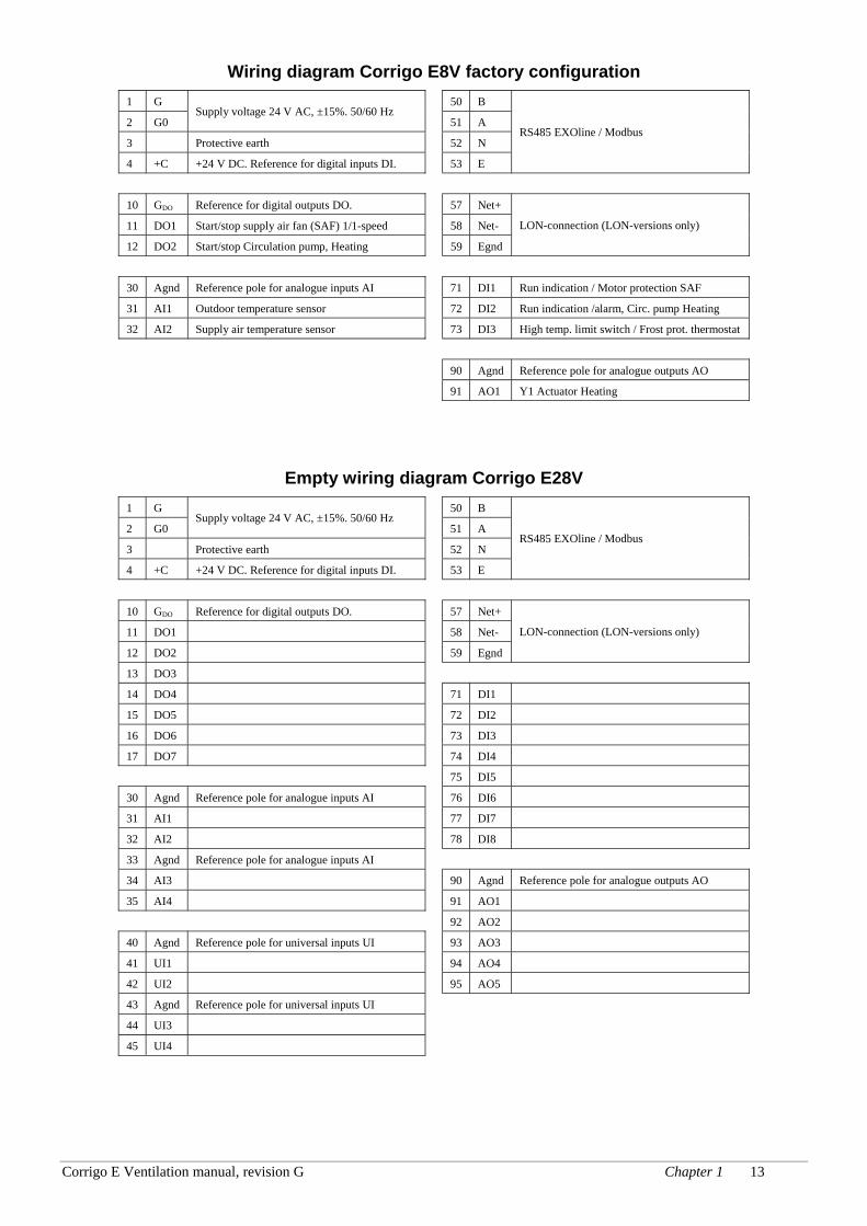
Wiring diagram Corrigo E8V factory configuration 1 G 50 B
2 G0 Supply voltage 24 V AC, ±15%. 50/60 Hz
51 A
3 Protective earth 52 N
4 +C +24 V DC. Reference for digital inputs DI. 53 E
RS485 EXOline / Modbus
10 GDO Reference for digital outputs DO. 57 Net+
11 DO1 Start/stop supply air fan (SAF) 1/1-speed 58 Net-
12 DO2 Start/stop Circulation pump, Heating 59 Egnd
LON-connection (LON-versions only)
30 Agnd Reference pole for analogue inputs AI 71 DI1 Run indication / Motor protection SAF
31 AI1 Outdoor temperature sensor 72 DI2 Run indication /alarm, Circ. pump Heating
32 AI2 Supply air temperature sensor 73 DI3 High temp. limit switch / Frost prot. thermostat
90 Agnd Reference pole for analogue outputs AO
91 AO1 Y1 Actuator Heating
Empty wiring diagram Corrigo E28V 1 G 50 B
2 G0 Supply voltage 24 V AC, ±15%. 50/60 Hz
51 A
3 Protective earth 52 N
4 +C +24 V DC. Reference for digital inputs DI. 53 E
RS485 EXOline / Modbus
10 GDO Reference for digital outputs DO. 57 Net+
11 DO1 58 Net-
12 DO2 59 Egnd
LON-connection (LON-versions only)
13 DO3
14 DO4 71 DI1
15 DO5 72 DI2
16 DO6 73 DI3
17 DO7 74 DI4
75 DI5
30 Agnd Reference pole for analogue inputs AI 76 DI6
31 AI1 77 DI7
32 AI2 78 DI8
33 Agnd Reference pole for analogue inputs AI
34 AI3 90 Agnd Reference pole for analogue outputs AO
35 AI4 91 AO1
92 AO2
40 Agnd Reference pole for universal inputs UI 93 AO3
41 UI1 94 AO4
42 UI2 95 AO5
43 Agnd Reference pole for universal inputs UI
44 UI3
45 UI4
Corrigo E Ventilation manual, revision G Chapter 1 14
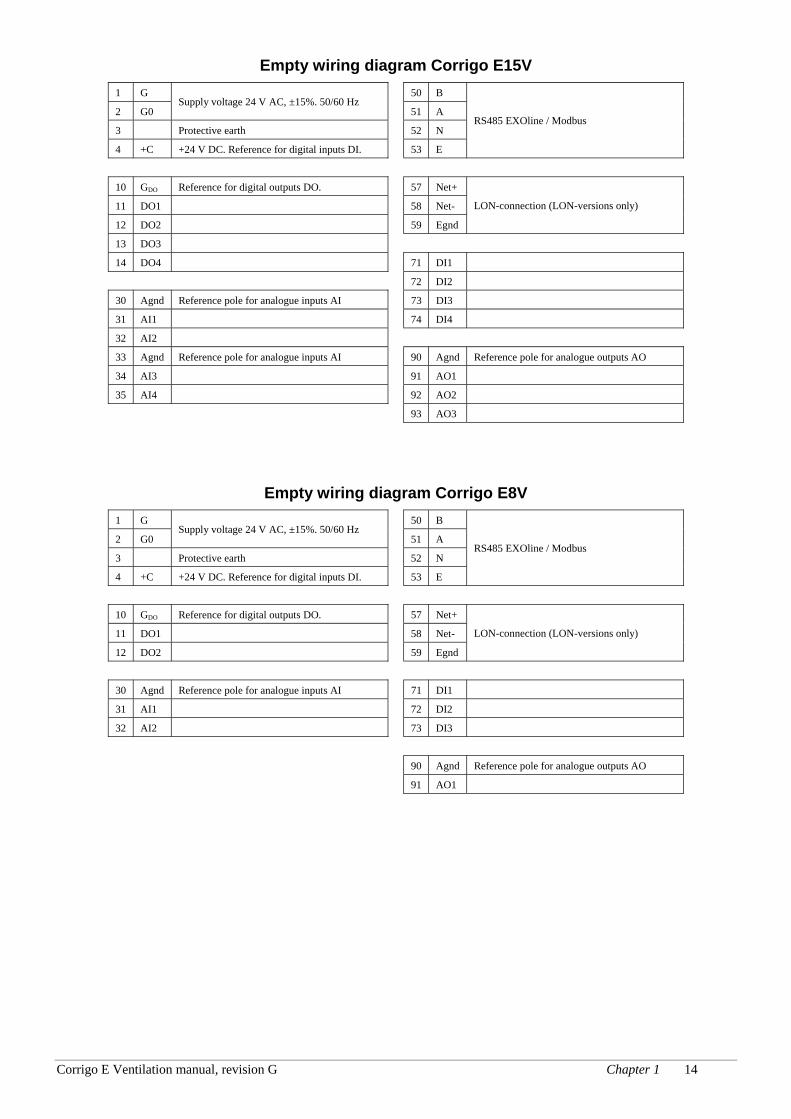
Empty wiring diagram Corrigo E15V 1 G 50 B
2 G0 Supply voltage 24 V AC, ±15%. 50/60 Hz
51 A
3 Protective earth 52 N
4 +C +24 V DC. Reference for digital inputs DI. 53 E
RS485 EXOline / Modbus
10 GDO Reference for digital outputs DO. 57 Net+
11 DO1 58 Net-
12 DO2 59 Egnd
LON-connection (LON-versions only)
13 DO3
14 DO4 71 DI1
72 DI2
30 Agnd Reference pole for analogue inputs AI 73 DI3
31 AI1 74 DI4
32 AI2
33 Agnd Reference pole for analogue inputs AI 90 Agnd Reference pole for analogue outputs AO
34 AI3 91 AO1
35 AI4 92 AO2
93 AO3
Empty wiring diagram Corrigo E8V 1 G 50 B
2 G0 Supply voltage 24 V AC, ±15%. 50/60 Hz
51 A
3 Protective earth 52 N
4 +C +24 V DC. Reference for digital inputs DI. 53 E
RS485 EXOline / Modbus
10 GDO Reference for digital outputs DO. 57 Net+
11 DO1 58 Net-
12 DO2 59 Egnd
LON-connection (LON-versions only)
30 Agnd Reference pole for analogue inputs AI 71 DI1
31 AI1 72 DI2
32 AI2 73 DI3
90 Agnd Reference pole for analogue outputs AO
91 AO1
Corrigo E Ventilation manual, revision G Chapter 4 Commissioning 15
Chapter 4 Commissioning
General Before the Corrigo can be used it must be configured, inputs and outputs must be assigned and all relevant parameters must be set.
All commissioning can be done using the Corrigo front panel display and buttons or using the display unit E-DSP.
Corrigo E-tool The best way however, is to configure the Corrigo E by using Corrigo E-tool.
Corrigo E-tool is a PC-based configuration program specially developed to simplify the commissioning of the Corrigo E-series.
When using E-tool the whole configuration and all settings can be done on the computer and then be downloaded to the Corrigo. An infinite number of different configurations can be saved in computer memory for later use.
3.1. How to do it For configuration using E-tool, see the E-tool manual.
For configuration using the front panel there are two ways to go depending on how much help you need.
Option 1: • Jump straight to chapter 7 and 8 Display, LEDs and buttons and Access rights.
• After mastering the button and menu system, connect power to your Corrigo, log on at System level and go to the menu Configuration.
• For the time being, skip the configuration menu Inputs/Outputs and start by configuring Control functions.
• Run through the configuration menus in order and set whatever functions and parameters you wish to include. Use chapter 6 of this manual for reference. Keep track of which inputs and outputs you will need. To help you, there is a list of input and output functions provided in chapter 3, (3.2.3 Input / Output list.)
• Finally, configure Inputs/Outputs.
• Exit Configuration and go to Settings
• Set the control values in Settings
• Set the clock and scheduler functions in Time Settings.
• Set the control setpoints in Actual/Setpoint.
Your Corrigo should now be ready to run.
Option 2: Read this manual in the order given below: The manual has been designed to act as a guide through the commissioning. The last chapters of the manual, not listed below, cover menus and functions that are not used during commissioning.
Corrigo E Ventilation manual, revision G Chapter 4 Commissioning 16
Functional description Start by reading chapter 5. Functional description below. Some functions are essential to the working of the unit and must be included. Others are more of the nature of optional extras which can be excluded.
At the end of each function description there is a table of the necessary inputs and outputs to implement the function. At the end of the manual there is a list of all the analogue and digital inputs and outputs. As you read, mark in the list the inputs and outputs you will be using for the application you are building. Note that the universal inputs in Corrigo E28 can, individually, be configured as either analogue or digital inputs.
Display, buttons and LEDs Read chapter 7 on how to use the front panel buttons to navigate the Corrigo E menu system.
Access rights Chapter 8. Learn how to log on to the Corrigo E
Configuration Chapter 9. Configuration.
Connect power to the Corrigo. Using the buttons and menu system, go through the configuration menus covering the functions you wish to use.
On delivery the units already have the inputs and outputs assigned to various functions. These can, of course, be changed. In chapter 3 Installation and wiring there are two sets of wiring diagrams, one set showing the pre-configured input / output configuration and one set where you can fill your own configuration choices.
Settings Set the control parameters, P-band, I-time for the temperature control.
Set the control parameters for the pressure control if you have pressure- or flow- controlled fans.
Set the control parameters for the humidity control if activated.
Set the alarm parameters; alarm levels and delay times.
Time Settings Set the clock and calendar functions.
Setpoints Set all the setpoints for all active control loops.
Hand/Auto Learn to use manual control. Very useful for testing out your system.
Corrigo E Ventilation manual, revision G Chapter 5 Functional description 17
Chapter 5 Functional description
5.1 Temperature control
General Corrigo E has a choice of the following control modes:
1. Supply air control
2. Outdoor temperature compensated supply air control
3. Cascaded room temperature control
4. Outdoor temperature dependent switching between room control and supply air control
5. Outdoor temperature dependent switching between exhaust air control and supply air control
6. Exhaust air control
The supply air temperature controller is reverse acting, i. e. the output will increase for decreasing temperature. The controller is a PI-controller with settable P-band and I-time.
In the first two modes the supply air temperature will be controlled using the supply air temperature and the user setpoint values as control inputs.
In modes 3 and 6 the supply air is controlled as part of a cascade controller together with the room/exhaust temperature controller. The room/exhaust temperature offset will dictate the supply air temperature setpoint.
Mode 4 and 5 vary according to the outdoor temperature: Supply air control in winter and cascaded room control or cascaded exhaust air control in summer.
In applications with mixing dampers instead of heat exchanger the signal for the damper control will be reversed compared to the signal for heat exchanger control i. e. decreasing signal on increasing heat demand. This is done automatically on configuring the exchanger output = dampers.
The heater can be either a hot water heater battery or an electric heater.
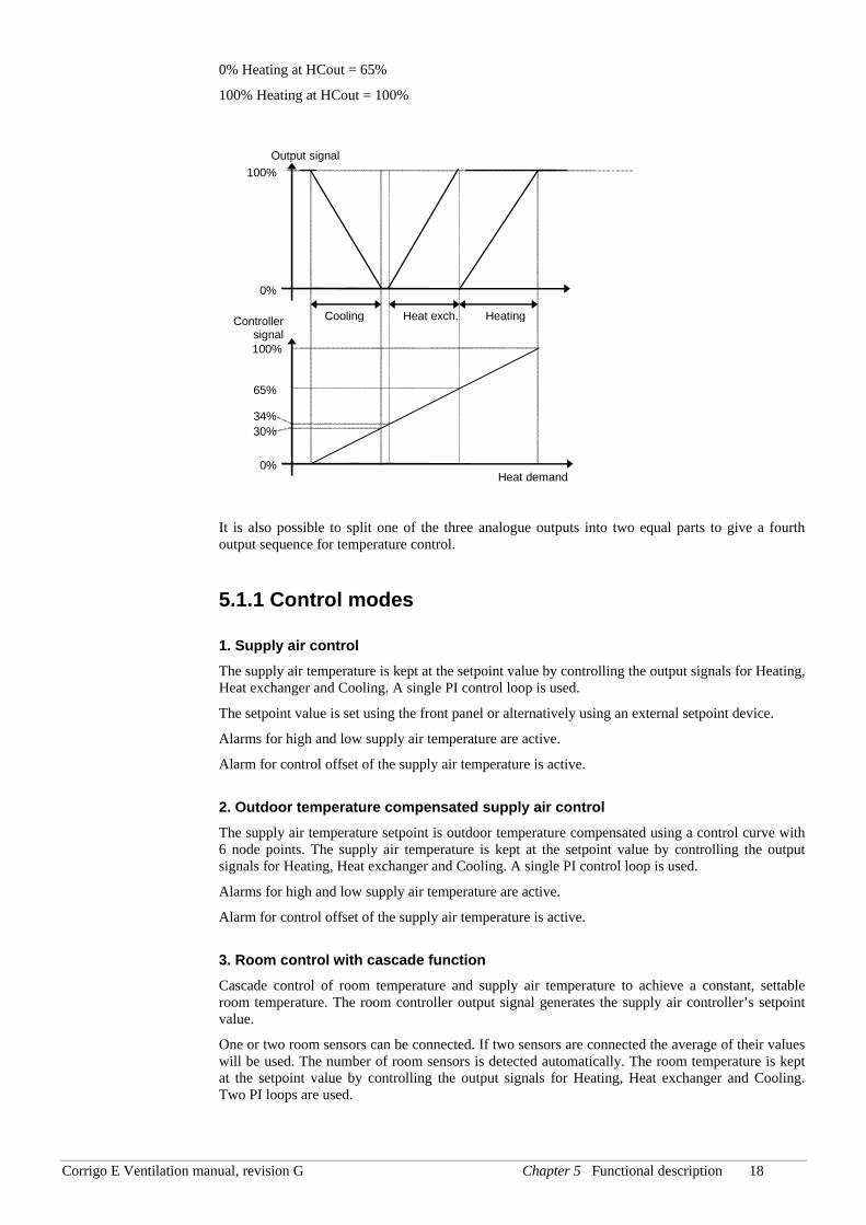
Outputs The supply air controller output is split between one or more of the output blocks Y1, Y2 and Y3 for heating, heat exchanger and cooling. The output blocks can be bound to either analogue 0…10 V DC outputs or to 3-position increase/decrease outputs.
Each output block has two parameters for setting the control range:
Controller signal at which the output should be 0%
Controller signal at which the output should be 100%
These settings are used to establish the output activation order and to split the P-band between the outputs.
For example:
0% Cooling at HCout = 30%
100% Cooling at HCout = 0%
0% Heat exch. at HCout =34%
100% Heat exch. at HCout = 65%
Corrigo E Ventilation manual, revision G Chapter 5 Functional description 18
0% Heating at HCout = 65%
100% Heating at HCout = 100%
It is also possible to split one of the three analogue outputs into two equal parts to give a fourth output sequence for temperature control.
5.1.1 Control modes
1. Supply air control The supply air temperature is kept at the setpoint value by controlling the output signals for Heating, Heat exchanger and Cooling. A single PI control loop is used.
The setpoint value is set using the front panel or alternatively using an external setpoint device.
Alarms for high and low supply air temperature are active.
Alarm for control offset of the supply air temperature is active.
2. Outdoor temperature compensated supply air control The supply air temperature setpoint is outdoor temperature compensated using a control curve with 6 node points. The supply air temperature is kept at the setpoint value by controlling the output signals for Heating, Heat exchanger and Cooling. A single PI control loop is used.
Alarms for high and low supply air temperature are active.
Alarm for control offset of the supply air temperature is active.
3. Room control with cascade function Cascade control of room temperature and supply air temperature to achieve a constant, settable room temperature. The room controller output signal generates the supply air controller’s setpoint value.
One or two room sensors can be connected. If two sensors are connected the average of their values will be used. The number of room sensors is detected automatically. The room temperature is kept at the setpoint value by controlling the output signals for Heating, Heat exchanger and Cooling. Two PI loops are used.
Controller signal
HeatingHeat exch.Cooling
Output signal
0%
100%
0%
100%
Heat demand
30%
65%
34%
Corrigo E Ventilation manual, revision G Chapter 5 Functional description 19
4. Outdoor temperature dependent switching between supply air temperature control and room temperature control When the outdoor temperature is lower than a settable limit (winter), outdoor compensated supply air temperature control will be active, otherwise (summer) cascaded room temperature control.
5. Outdoor temperature dependent switching between supply air temperature control and exhaust air temperature control When the outdoor temperature is lower than a settable limit, outdoor compensated supply air temperature control will be active, otherwise cascaded exhaust air temperature control.
6. Exhaust air control with cascade function Cascade control of exhaust air temperature and supply air temperature to achieve a constant, settable room temperature. The exhaust air controller output signal generates the supply air controller’s setpoint value. The exhaust air temperature is kept at the setpoint value by controlling the output signals for Heating, Heat exchanger and Cooling. Two PI loops are used.
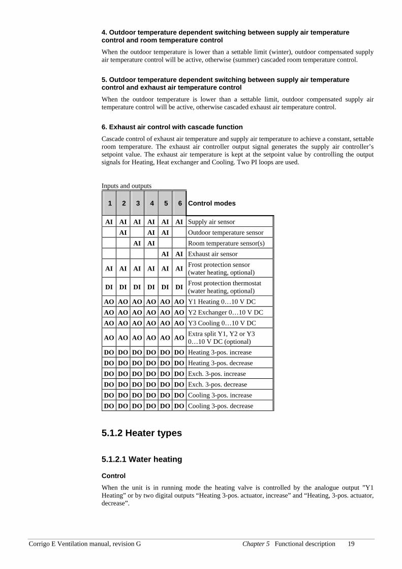
Inputs and outputs
1 2 3 4 5 6 Control modes
AI AI AI AI AI AI Supply air sensor AI AI AI Outdoor temperature sensor AI AI Room temperature sensor(s) AI AI Exhaust air sensor
AI AI AI AI AI AI Frost protection sensor (water heating, optional)
DI DI DI DI DI DI Frost protection thermostat (water heating, optional)
AO AO AO AO AO AO Y1 Heating 0…10 V DC AO AO AO AO AO AO Y2 Exchanger 0…10 V DC AO AO AO AO AO AO Y3 Cooling 0…10 V DC
AO AO AO AO AO AO Extra split Y1, Y2 or Y3 0…10 V DC (optional)
DO DO DO DO DO DO Heating 3-pos. increase DO DO DO DO DO DO Heating 3-pos. decrease DO DO DO DO DO DO Exch. 3-pos. increase DO DO DO DO DO DO Exch. 3-pos. decrease DO DO DO DO DO DO Cooling 3-pos. increase DO DO DO DO DO DO Cooling 3-pos. decrease
5.1.2 Heater types
5.1.2.1 Water heating
Control When the unit is in running mode the heating valve is controlled by the analogue output ”Y1 Heating” or by two digital outputs “Heating 3-pos. actuator, increase” and “Heating, 3-pos. actuator, decrease”.
Corrigo E Ventilation manual, revision G Chapter 5 Functional description 20
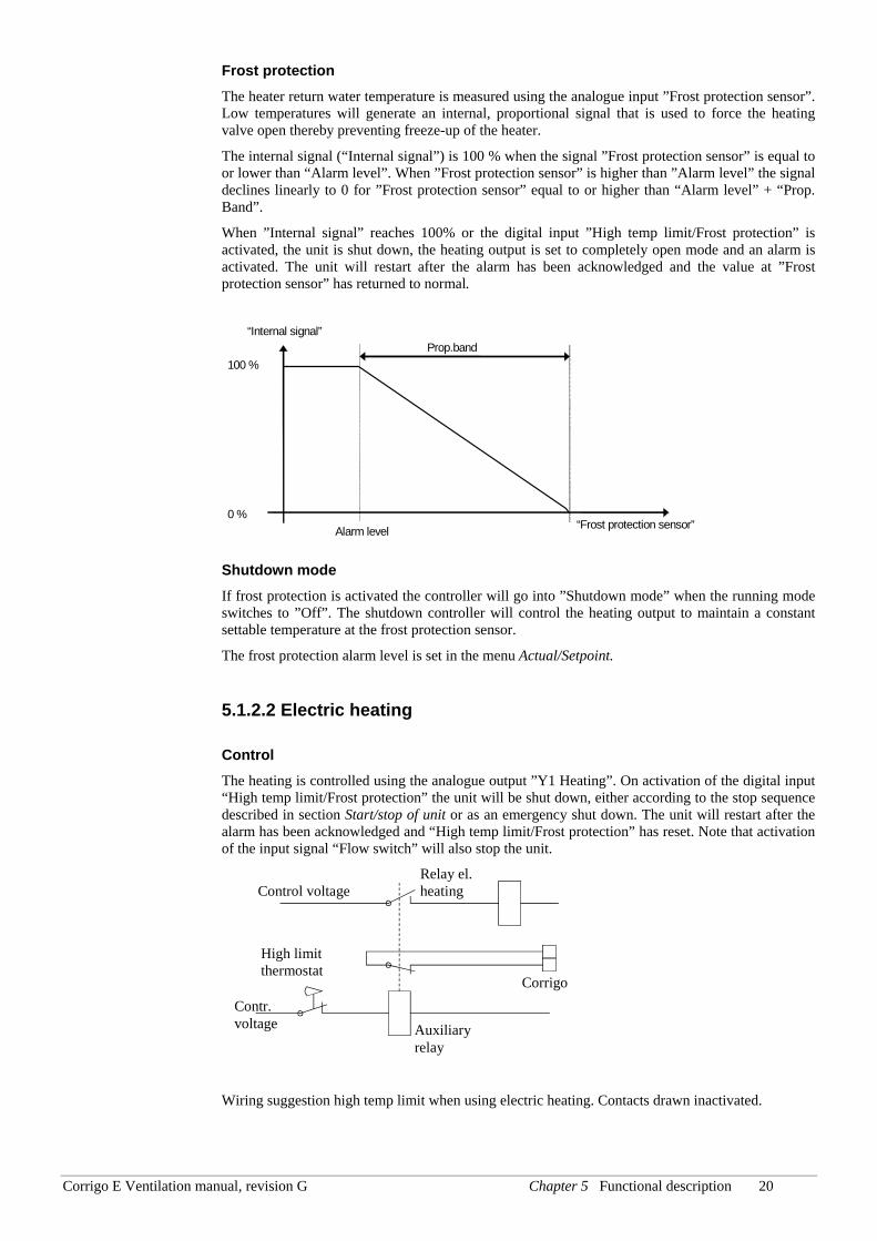
Frost protection The heater return water temperature is measured using the analogue input ”Frost protection sensor”. Low temperatures will generate an internal, proportional signal that is used to force the heating valve open thereby preventing freeze-up of the heater.
The internal signal (“Internal signal”) is 100 % when the signal ”Frost protection sensor” is equal to or lower than “Alarm level”. When ”Frost protection sensor” is higher than ”Alarm level” the signal declines linearly to 0 for ”Frost protection sensor” equal to or higher than “Alarm level” + “Prop. Band”.
When ”Internal signal” reaches 100% or the digital input ”High temp limit/Frost protection” is activated, the unit is shut down, the heating output is set to completely open mode and an alarm is activated. The unit will restart after the alarm has been acknowledged and the value at ”Frost protection sensor” has returned to normal.
Shutdown mode If frost protection is activated the controller will go into ”Shutdown mode” when the running mode switches to ”Off”. The shutdown controller will control the heating output to maintain a constant settable temperature at the frost protection sensor.
The frost protection alarm level is set in the menu Actual/Setpoint.
5.1.2.2 Electric heating
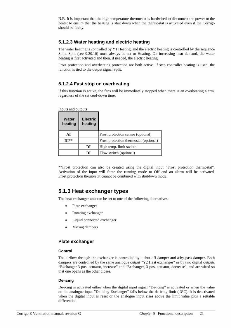
Control The heating is controlled using the analogue output ”Y1 Heating”. On activation of the digital input “High temp limit/Frost protection” the unit will be shut down, either according to the stop sequence described in section Start/stop of unit or as an emergency shut down. The unit will restart after the alarm has been acknowledged and “High temp limit/Frost protection” has reset. Note that activation of the input signal “Flow switch” will also stop the unit.
Relay el. heating Control voltage
Contr. voltage
High limit thermostat
Auxiliary relay
Corrigo
Wiring suggestion high temp limit when using electric heating. Contacts drawn inactivated.
“Frost protection sensor”
“Internal signal”
0 %
100 % Prop.band
Alarm level
Corrigo E Ventilation manual, revision G Chapter 5 Functional description 21
N.B. It is important that the high temperature thermostat is hardwired to disconnect the power to the heater to ensure that the heating is shut down when the thermostat is activated even if the Corrigo should be faulty.
5.1.2.3 Water heating and electric heating The water heating is controlled by Y1 Heating, and the electric heating is controlled by the sequence Split. Split (see 9.20.10) must always be set to Heating. On increasing heat demand, the water heating is first activated and then, if needed, the electric heating.
Frost protection and overheating protection are both active. If step controller heating is used, the function is tied to the output signal Split.
5.1.2.4 Fast stop on overheating If this function is active, the fans will be immediately stopped when there is an overheating alarm, regardless of the set cool-down time.
Inputs and outputs
Water heating
Electric heating
AI Frost protection sensor (optional) DI** Frost protection thermostat (optional)
DI High temp. limit switch DI Flow switch (optional)
**Frost protection can also be created using the digital input “Frost protection thermostat”. Activation of the input will force the running mode to Off and an alarm will be activated. Frost protection thermostat cannot be combined with shutdown mode.
5.1.3 Heat exchanger types The heat exchanger unit can be set to one of the following alternatives:
• Plate exchanger
• Rotating exchanger
• Liquid connected exchanger
• Mixing dampers
Plate exchanger
Control The airflow through the exchanger is controlled by a shut-off damper and a by-pass damper. Both dampers are controlled by the same analogue output ”Y2 Heat exchanger” or by two digital outputs “Exchanger 3-pos. actuator, increase” and “Exchanger, 3-pos. actuator, decrease”, and are wired so that one opens as the other closes.
De-icing De-icing is activated either when the digital input signal ”De-icing” is activated or when the value on the analogue input ”De-icing Exchanger” falls below the de-icing limit (-3°C). It is deactivated when the digital input is reset or the analogue input rises above the limit value plus a settable differential.
Corrigo E Ventilation manual, revision G Chapter 5 Functional description 22
On de-icing:
A PI-controller compares the de-icing setpoint with the signal ”De-icing Exchanger”. The lesser of the output signal from this controller and the output from the ordinary controller is used as output to the dampers.
Rotating exchanger
Control Rotational speed is controlled by the analogue signal ”Y2 Heat exchanger” or by two digital outputs “Exchanger 3-pos. actuator, increase” and “Exchanger, 3-pos. actuator, decrease”. A rotation sentinel can be connected to the digital input ”Rotation sentinel Exchanger”. An alarm is generated if this input is activated at the same time as the analogue output signal is higher than 1.0V.
Liquid connected heat exchanger
Control A mixing valve in the exchanger circulation system is controlled by the analogue signal ”Y2 Heat exchanger” or by two digital outputs “Exchanger 3-pos. actuator, increase” and “Exchanger, 3-pos. actuator, decrease”.
The circulation pump (digital input ”start/stop CP Exchanger”) is started as soon as the actuator control signal is higher than 0.1V and is stopped when the valve has been closed for more than 30 minutes.
De-icing De-icing is activated when the value on the analogue input ”De-icing Exchanger” falls below the de-icing limit (-3°C). It is deactivated when the analogue input rises above the limit value plus a settable differential.
On de-icing:
A PI-controller compares the de-icing setpoint with the signal ”De-icing Exchanger”. The lesser of the output signal from this controller and the output from the ordinary controller is used as output to the actuator.
Outdoor temp control of exchanger Instead of using Y2 for analogue control of the heat exchanger it can be set to run on-off against outdoor temperature. The function controls a digital output “Exch control”, which is activated when the outdoor temperature falls below a set value. A heat exchanger alarm is activated if the input ”Rotation sentinel Exchanger” is activated when the output “Exch control” is active.
Mixing dampers
Control The analogue output ”Y2 Heat exchanger” controls two dampers for gradual mixing of fresh air and recirculated air. In this mode the output signal decreases with increasing heat demand.
CO2/VOC If demand controlled ventilation (see 5.3.2) is activated in combination with mixing dampers and the CO2-value increases above setpoint the dampers will move to permit more fresh air utilizing a P-function.
Minimum limit A fresh air minimum limit for can be set using the front panel. The limit value is settable between 0 and 100%.
Corrigo E Ventilation manual, revision G Chapter 5 Functional description 23
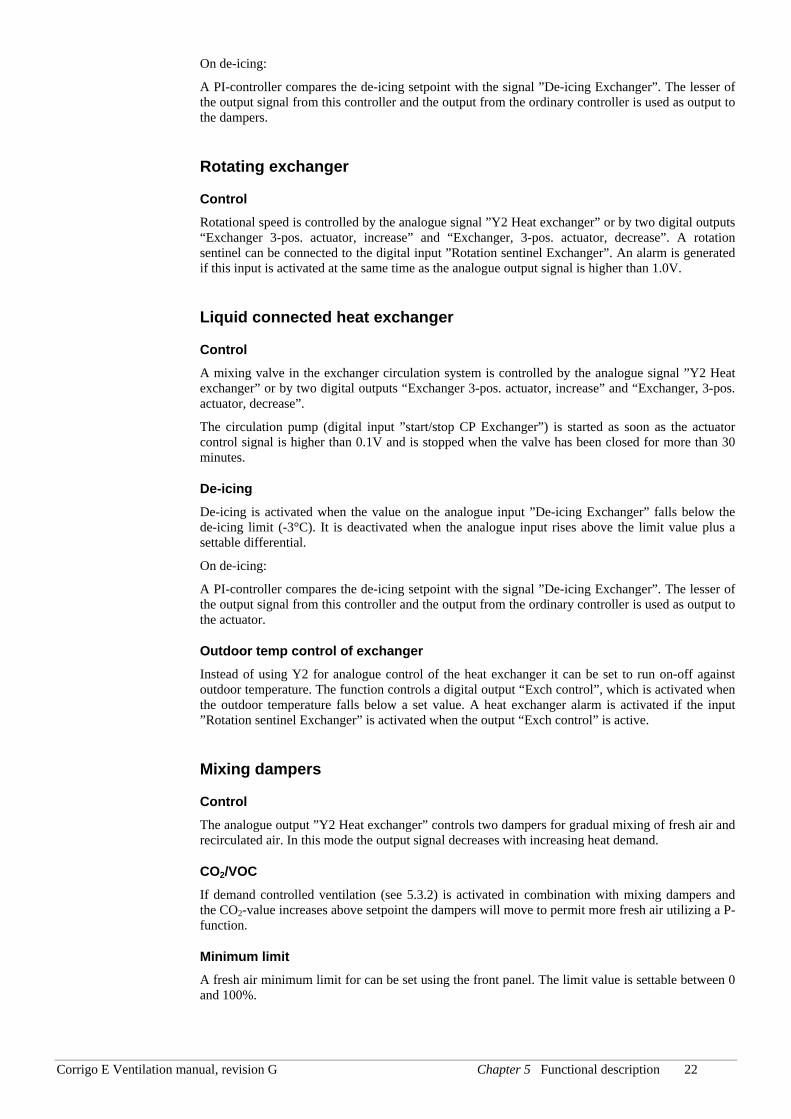
Inputs and outputs
Plate Rota-ting
Liquid Dam-pers
AI AI AI AI Outdoor temp sensor (optional, outd. temp start)
DO DO DO DO Activation exchanger (optional, outd. temp start)
AI AI De-icing sensor (optional) DI DI De-icing signal (optional)
DI Rotation sentinel, exchanger (optional)
5.1.4 Step controller Heating/ DX cooling As alternative or complement to the above mentioned analogue control, heating and cooling can be activated in steps. The internal signal is then used to activate digital outputs for control of the heaters/chillers. Up to four heater outputs and three cooler outputs can be configured. There are two possible modes:
Sequential Each output step has individually settable on- and off-values in % of the control signal. The number of steps is equal to the number of heater/chiller groups. Min on and off times can be set.
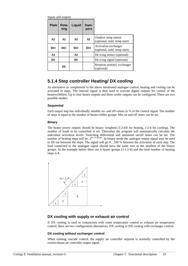
Binary The heater power outputs should be binary weighted (1:2:4:8 for heating, 1:2:4 for cooling). The number of loads to be controlled is set. Thereafter the program will automatically calculate the individual activation levels. Switching differential and minimum on/off times can be set. The number of heating steps will be: 2no. of groups. In binary mode the analogue output signal may be used to fill out between the steps. The signal will go 0…100 % between the activation of each step. The load connected to the analogue signal should have the same size as the smallest of the binary groups. In the example below there are 4 heater groups (1:1:2:4) and the total number of heating steps is 8.
1
1
1
1
2
4
2
Y1 = 1
DX cooling with supply or exhaust air control If DX cooling is used in conjunction with room temperature control or exhaust air temperature control, there are two configuration alternatives, DX cooling or DX cooling with exchanger control.
DX cooling without exchanger control When running cascade control, the supply air controller setpoint is normally controlled by the room/exhaust air controller output signal.
Corrigo E Ventilation manual, revision G Chapter 5 Functional description 24
When DX cooling is activated, the cooling controller setpoint is lowered to 5 degrees (settable) below the setpoint given by the room/exhaust air controller. This prevents the DX cooling from being activated/deactivated too often.
DX cooling with exchanger control When running cascade control, the supply air controller setpoint is normally controlled by the room/exhaust air controller output signal.
When DX cooling is activated, the cooling controller setpoint is lowered to 5 degrees (settable) below the setpoint given by the room/exhaust air controller. This prevents the DX cooling from being activated/deactivated too often. If the supply air temperature falls below the setpoint given by the room/exhaust air controller, the heat exchanger output will be activated in order to try to maintain the supply air setpoint given by the room/exhaust air controller. The output uses P-control with a P-band of half the setpoint lowering (settable, 2.5°C as default). The setpoint given by the room/exhaust air controller cannot drop below the set min limit. When there is no longer a cooling demand, the cooling controller setpoint will return to the value given by the room/exhaust air controller.
Note: The function cannot be used if the exchanger signal controls a mixing damper.
Example:
The room controller gives a supply air setpoint of 16°C. If there is a cooling demand, the cooling controller setpoint is lowered to 11°C (16 – 5) and DX cooling is activated. Should the supply air temperature sink below 16°C, the exchanger output will be activated and reach 100% output when the supply air temperature has fallen to 13.5°C (16 – 2.5).
Blocking of DX cooling at low outdoor temperature DX cooling can be blocked when the outdoor temperature is low. The temperature limit is settable (+13°C default) and has a fixed 1 degree hysteresis.
Blocking of DX cooling at low supply air fan speed When DX cooling is used in conjunction with pressure controlled or flow controlled fans it is possible to block DX cooling if the supply air fan control signal falls below a preset values. The blocking level is individually settable for each DX cooling step.
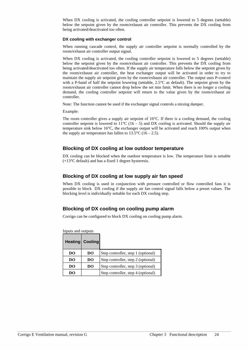
Blocking of DX cooling on cooling pump alarm Corrigo can be configured to block DX cooling on cooling pump alarm.
Inputs and outputs
Heating Cooling
DO DO Step controller, step 1 (optional) DO DO Step controller, step 2 (optional) DO DO Step controller, step 3 (optional) DO Step controller, step 4 (optional)
Corrigo E Ventilation manual, revision G Chapter 5 Functional description 25
5.1.5 Support control Support control is normally used when room temperature control or exhaust air control has been configured. When exhaust air control is configured a room sensor must be installed. “Support control Heating” or “Support control Cooling” will run if Support control is configured, the running mode is in Off-state (timer control OFF and not in extended running) and if conditions call for support control (see below). Minimum run time is settable 0 to 720 minutes (FS= 20 minutes).
Support control heating Demand for support control heating is when the room temperature is lower than the start value which is settable 0 to 30°C. The fans will run at the preset speed, the heater and the heat exchanger are controlled by the supply air temperature controller with the configured max limitation for the supply air (FS=30°C) as setpoint and the cooling is shut off (0%). Support control heating stops when the room temperature rises 1K over the start value and the minimum run time has been exceeded or the running mode changes to ”On”.
Support control cooling Demand for support control cooling is when the room temperature is higher than the start value which is settable 20 to 50°C. The fans will run at the preset speed, the heater and the heat exchanger are shut down (0%) and the cooling is controlled by the supply air temperature controller with the configured minimum limitation (FS=15°C) as setpoint. Support control cooling stops when the temperature falls 1K below the start value and the minimum run time has been exceeded or the running mode changes to ”On”.
Support control can also be configured when supply air temperature control is used, if a room sensor is installed. The controller uses the configured min (FS=15°C) and max (FS=30°C) limitation values as support control setpoints. However, in this case the min and max limitation values cannot be changed. To change the values, temporarily configure room control, change the min and max values and then change back to supply air control.
5.1.6 Free cooling This function is used during the summer to cool the building night-time using cool outdoor air, thereby reducing the need for cooling during the day and saving energy.
Free cooling is started at 12.00 p.m. if all timer channels are OFF and the daytime outdoor temperature has been higher than a settable value (22°C).
The fans are started and run for at least 3 minutes.
However, the fans are not started if the unit is not set on normal speed according to the timer channel for the following day. (No running time set during the next 24 hours.)
Stop conditions:
Free cooling stops at 06.00 a.m. or if the outdoor temperature rises above a settable value (+15°C) or if the outdoor temperature falls below a settable value (+5°C, condensation risk) or if the room temperature falls below a settable value (+18°C).
When free cooling is active the fans run at normal speed but the outputs Y1- Heating, Y2- Heat exchanger and Y3-Cooling are shut down.
Inputs and outputs AI Outdoor temperature sensor AI Room temperature sensor(s)
Corrigo E Ventilation manual, revision G Chapter 5 Functional description 26
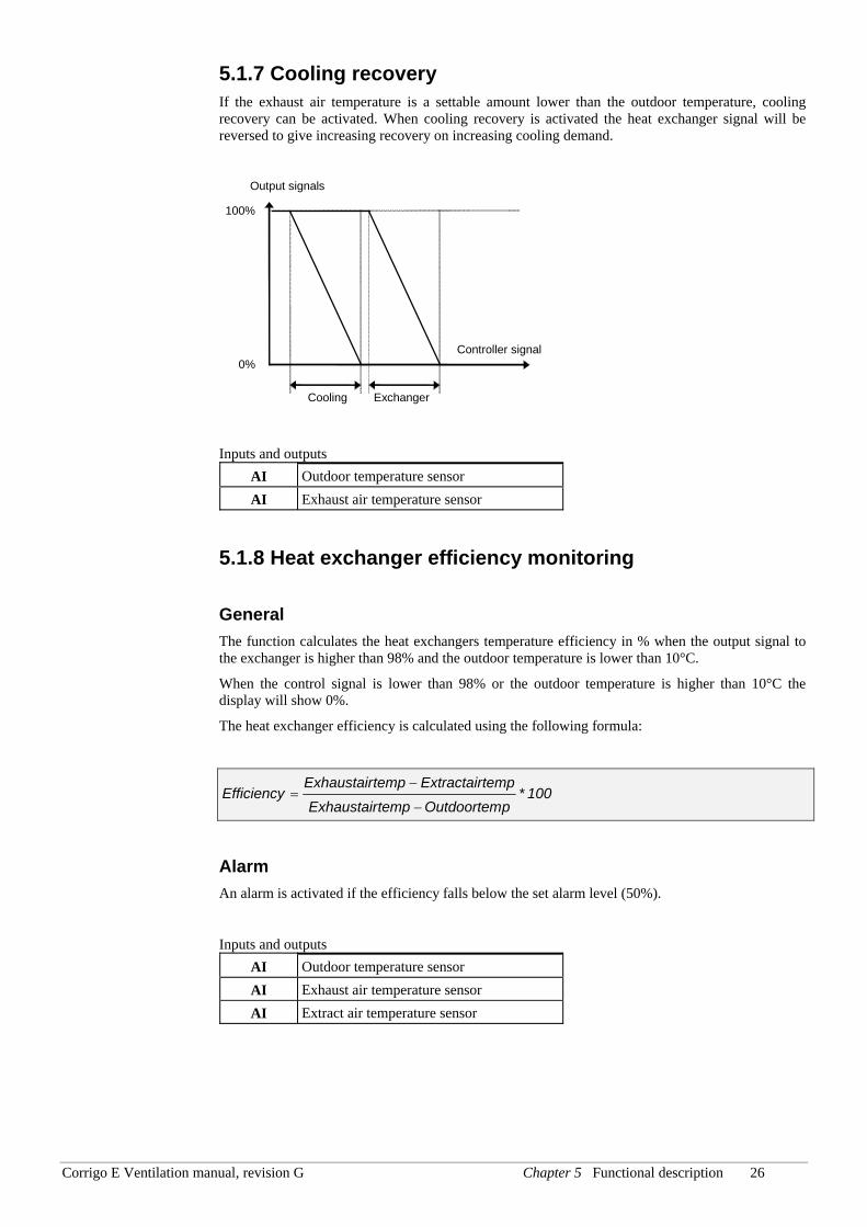
5.1.7 Cooling recovery If the exhaust air temperature is a settable amount lower than the outdoor temperature, cooling recovery can be activated. When cooling recovery is activated the heat exchanger signal will be reversed to give increasing recovery on increasing cooling demand.
Output signals
Controller signal0%
100%
Exchanger Cooling
Inputs and outputs AI Outdoor temperature sensor AI Exhaust air temperature sensor
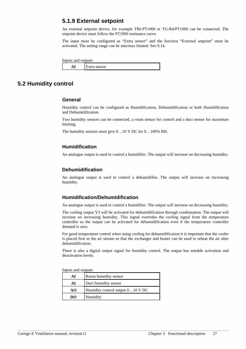
5.1.8 Heat exchanger efficiency monitoring
General The function calculates the heat exchangers temperature efficiency in % when the output signal to the exchanger is higher than 98% and the outdoor temperature is lower than 10°C.
When the control signal is lower than 98% or the outdoor temperature is higher than 10°C the display will show 0%.
The heat exchanger efficiency is calculated using the following formula:
100*pOutdoortemtempExhaustair
tempExtractairtempExhaustairEfficiency
−
−=
Alarm An alarm is activated if the efficiency falls below the set alarm level (50%).
Inputs and outputs AI Outdoor temperature sensor AI Exhaust air temperature sensor AI Extract air temperature sensor
Corrigo E Ventilation manual, revision G Chapter 5 Functional description 27
5.1.9 External setpoint An external setpoint device, for example TBI-PT1000 or TG-R4/PT1000 can be connected. The setpoint device must follow the PT1000 resistance curve.
The input must be configured as “Extra sensor” and the function “External setpoint” must be activated. The setting range can be min/max limited. See 9.14.
Inputs and outputs AI Extra sensor
5.2 Humidity control
General Humidity control can be configured as Humidification, Dehumidification or both Humidification and Dehumidification.
Two humidity sensors can be connected, a room sensor for control and a duct sensor for maximum limiting.
The humidity sensors must give 0…10 V DC for 0…100% RH.
Humidification An analogue output is used to control a humidifier. The output will increase on decreasing humidity.
Dehumidification An analogue output is used to control a dehumidifier. The output will increase on increasing humidity.
Humidification/Dehumidification An analogue output is used to control a humidifier. The output will increase on decreasing humidity.
The cooling output Y3 will be activated for dehumidification through condensation. The output will increase on increasing humidity. This signal overrides the cooling signal from the temperature controller so the output can be activated for dehumidification even if the temperature controller demand is zero.
For good temperature control when using cooling for dehumidification it is important that the cooler is placed first in the air stream so that the exchanger and heater can be used to reheat the air after dehumidification.
There is also a digital output signal for humidity control. The output has settable activation and deactivation levels.
Inputs and outputs AI Room humidity sensor
AI Duct humidity sensor
AO Humidity control output 0…10 V DC
DO Humidity
Corrigo E Ventilation manual, revision G Chapter 5 Functional description 28
5.3 Fan control
General Fans can be single speed, 2 speed or pressure control via frequency converter.
Single speed fans are controlled using the digital outputs 1/1-speed supply air fan (SAF) and 1/1-speed exhaust air fan (EAF).
2-speed fans are controlled using the digital outputs 1/1-speed SAF, 1/1-speed EAF, 1/2-speed SAF and 1/2-speed EAF giving normal speed and reduced speed.
Frequency control uses one analogue output per fan for constant pressure control. There are two setpoints for each fan. When in this document reference is made to timer channels for normal speed and reduced speed it is understood that in the case of pressure control it implies changing between the two setpoint values.
Frequency controlled fans can also be configured to be run with fixed output values.
Outdoor compensation When running pressure control, it is also possible to outdoor compensate the pressure.
Crosswise interlock Via the display it is possible to configure crosswise interlocking between the supply air and exhaust air fans.
Timer control, interlock The fans are normally controlled by the timer channels for normal and reduced speed. At very low outdoor temperature 2-speed and pressure/flow controlled fans can be forced to low speed. The limit temperature is settable and the function has a differential of 2K.
Normal, reduced speed Units with 2-speed or pressure control fans are always started at reduced speed. After a settable time, Corrigo switches to normal speed if normal speed is valid at start-up. When 2-speed fans are switched from Reduced to Normal speed, Reduced speed is first disengaged. About 2 sec later, Normal speed is activated.
When Corrigo switches from Normal to Reduced speed, there is a settable retardation time from the disengagement of Normal speed to the activation of Reduced speed. See 9.20.2
The exhaust air fan and the supply air fan have individual start and stop delays which are normally set so that the exhaust air fan is started before the supply air fan. If there are not enough digital outputs for individual control, both fans will have to be started using the signal for the supply air fan, and the delay be created using an external time relay.
5.3.1 Pressure control When running pressure control, two analogue output signals are used for supply and exhaust air respectively. The signals control the fan speeds via frequency converters, thereby maintaining constant pressure. A digital activation signal is normally used for each fan (SAF ½ speed and EAF ½ speed), for sending a start signal to the frequency converters. There are also digital activation signals (SAF frequency and EAF frequency) which can be used as start signals for the frequency converters. These are activated when the output signal sent to each respective frequency converter rises above 0.1 V (Demand controlled run-signal).
For the supply and exhaust air fans, there are two individually settable setpoint values, one corresponding to normal speed and one corresponding to reduced speed. Changing between the two setpoint values is done using the timer channels for normal and reduced speed.
Outdoor compensation When running pressure control, it is also possible to outdoor compensate the pressure setpoint value.
Corrigo E Ventilation manual, revision G Chapter 5 Functional description 29
The outdoor compensation is linear and is set using two parameter pairs which give the value of the compensation at two different outdoor temperatures. The compensation can be positive or negative.
The outdoor compensation is set in the menu Actual/Setpoint.
Using E-tool, you can also choose to only outdoor compensate the pressure value of the supply air fan. In that case, the exhaust air fan is controlled with constant flow, independent of the outdoor temperature.
Air flow Instead of giving a pressure setpoint value it is possible to use an airflow volume value in m3/sec instead. The value from the pressure transmitter is recalculated to a volume flow using the formula below and the fans will be controlled to give a constant flow.
Flow = K *Δ PX
Where K and X are settable constants dependent on the fan size and ΔP is the differential pressure, measured in Pa, over the fan. x is normally 0.5 indicating that the flow is proportional to the square root of the differential pressure.
Outdoor compensation Also when running flow control, it is possible to outdoor compensate the setpoint value.
The outdoor compensation is linear and is set using two parameter pairs which give the value of the compensation at two different outdoor temperatures. The compensation can be positive or negative.
The outdoor compensation is set in the menu Actual/Setpoint.
Using E-tool, you can also choose to only outdoor compensate the flow of the supply air fan. In that case, the exhaust air fan is controlled using constant flow, independent of the outdoor temperature.
Fixed output signal Frequency controlled fans can be controlled at a fixed rotational speed. The rotational speed is selected by setting a fixed output signal (0 – 100%). Values for normal and reduced speed can be configured for each fan.
Fans that are run with a fixed output signal can also be outdoor compensated (see the section above). In this mode, pressure sensors are not needed.
Minimum limit For frequency controlled fans an adjustable minimum limit can be set individually on the supply air and exhaust air fan control signals.
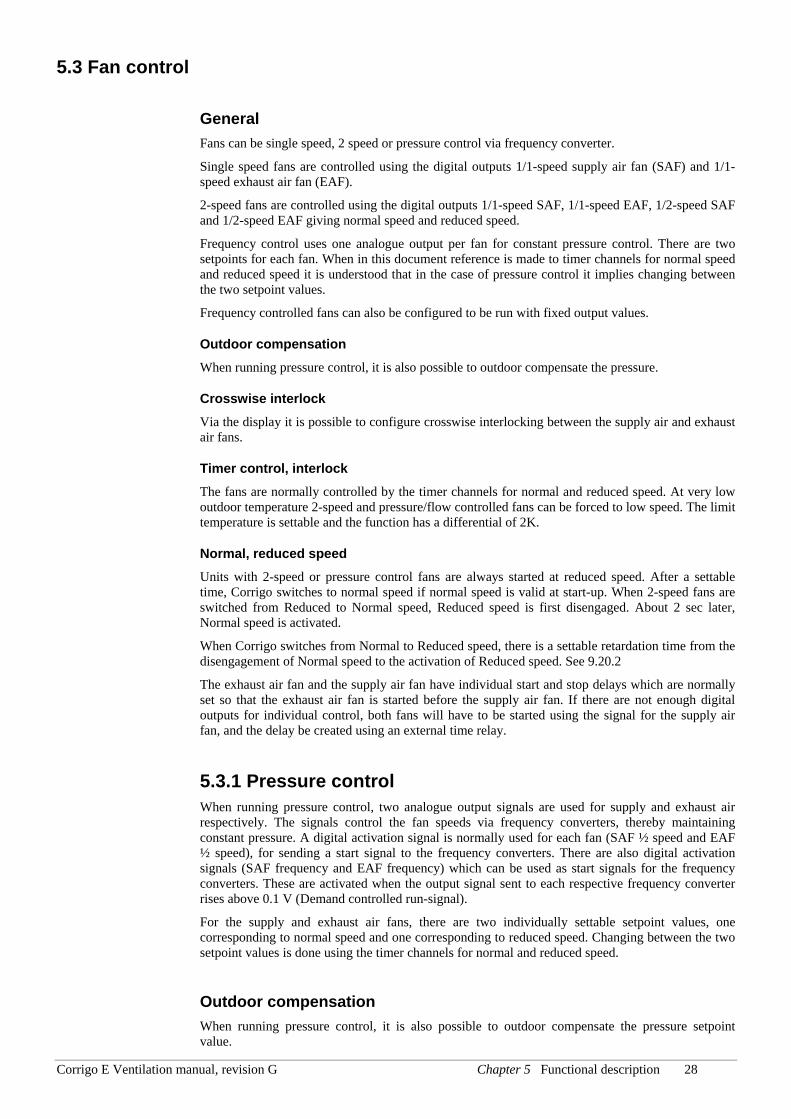
Inputs and outputs
1-speed
2-speed
Pres-sure/Flow
DO DO 1/1 speed start/stop SAF DO DO 1/1 speed start/stop EAF
DO DO 1/2 speed start/stop SAF DO DO 1/2 speed start/stop EAF DO SAF frequency start DO EAF frequency start
DI DI Indication/alarm SAF
Corrigo E Ventilation manual, revision G Chapter 5 Functional description 30
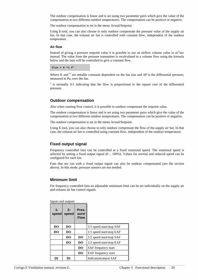
1-speed
2-speed
Pres-sure/Flow
DI DI Indication/alarm EAF AI Pressure transmitter SAF AI Pressure transmitter EAF AO Frequency converter SAF AO Frequency converter EAF
5.3.2 Demand controlled ventilation In applications with varying occupancy the fan speeds or mixing dampers can be controlled by the air quality as measured by a CO2/VOC-sensor.
Via the display the function can be activated/deactivated and also there is the possibility of choosing fan control or mixing dampers.
When the function is activated and combined with pressure controlled fans and the CO2/VOC-value rises above control value 1 the fans will start at low speed. Should CO2/VOC-value continue to rise the fan speed will also increase until the CO2/VOC-value reaches control value 2 at which the fans will be running at normal speed. The fans will stop when the CO2/VOC-value falls 160 ppm below control value 1.
When used with two-speed fans they will start using low speed when the CO2/VOC-value rises above control value 1 and switch to normal speed when the CO2/VOC-value reaches control value 2. The fans will stop when the CO2/VOC-value falls 160 ppm below control value 1.
If demand controlled ventilation is activated in combination with mixing dampers, and the CO2-value rises above the setpoint value, the dampers will let in more fresh air. The function is controlled by a P-controller.
Inputs and outputs
AI CO2/VOC sensor input
5.4 Pump control Digital inputs and outputs can be configured for pump control.
5.4.1 Heating circuit The circulation pump for the heating circuit will always run when the outdoor temperature is lower than a settable value (+10°C). At higher outdoor temperatures the pump will run when the heating output is larger than 0V.
The pump has a settable, shortest running time.
The pump will be exercised once daily at 3 p.m. for 1 minute or the set shortest running time, whichever is the longest.
5.4.2 Exchanger circuit, liquid connected exchangers The circulation pump for the exchanger circuit will run when the output to the exchanger valve is larger than 0V.
The pump will be exercised once daily at 3 p.m. for 1 minute or the set shortest running time, whichever is the longest.
Corrigo E Ventilation manual, revision G Chapter 5 Functional description 31
5.4.3 Cooling circuit The circulation pump for the cooling circuit will run when the output to the cooling valve is larger than 0V.
The pump will be exercised once daily at 3 p.m. for 1 minute or the set shortest running time, whichever is the longest.
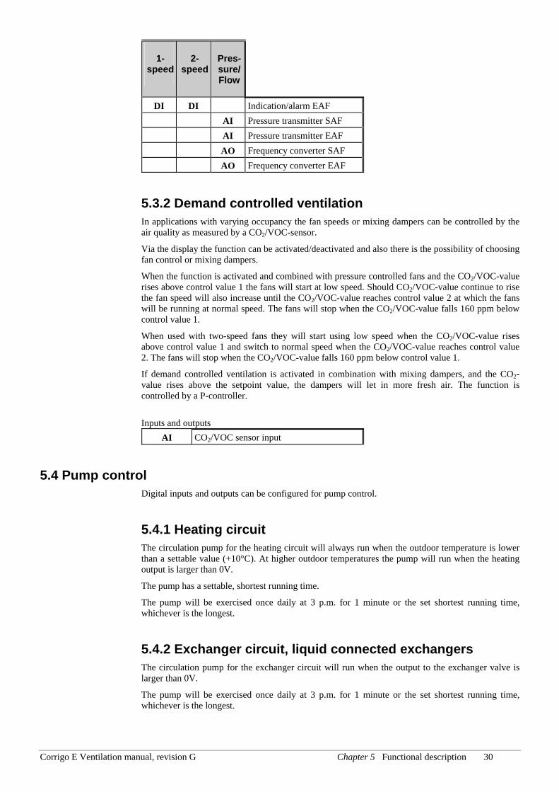
Inputs and outputs
Heat-ing
Exch Cool-ing
AI Outdoor temp sensor DO DO DO Start/stop circulation pump DI DI DI Run ind/alarm, circ. pump
5.5 Damper control
5.5.1 Close-off dampers The fresh air and extract air ducts close-off dampers can be controlled by digital outputs or be hard-wired to the supply air fan relays for normal and reduced speed in such a fashion that the damper is open when the supply air fan is running. When using pressure controlled fans the digital activation signal is activated as soon as the fan control signal is greater than 0.1V. This signal can be used to open the close-off damper.
5.5.2 Fire dampers Normally fire dampers are configured to open on fire alarm. Using the display it is however possible to reconfigure them to be normally open instead.
There is a digital input for detection of open and closed position of the fire dampers.
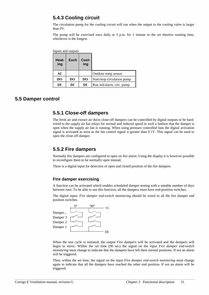
Fire damper exercising A function can be activated which enables scheduled damper testing with a settable number of days between runs. To be able to use this function, all the dampers must have end-position switches.
The digital input: Fire damper end-switch monitoring should be wired to all the fire damper end position switches.
When the test cycle is initiated, the output Fire dampers will be activated and the dampers will begin to move. Within the set time (90 sec) the signal on the input Fire damper end-switch monitoring must change to indicate that the dampers have left their normal positions. If not an alarm will be triggered.
Then, within the set time, the signal on the input Fire damper end-switch monitoring must change again to indicate that all the dampers have reached the other end position. If not an alarm will be triggered.
0° 90°
Damper... Damper 3 Damper 2 Damper 1
+C
DI
Corrigo E Ventilation manual, revision G Chapter 5 Functional description 32
When all dampers have reached the end position the output Fire dampers will be reset to drive the dampers back to normal position. Again, within the set time (90 sec) the signal on the input Fire damper end-switch monitoring must change to indicate that the dampers have left the end positions. If not an alarm will be triggered.
Then, within the set time, the signal on the input Fire damper end-switch monitoring must change again to indicate that all the dampers are back to their normal positions. If not an alarm will be triggered
The controller can be configured to stop the air handling unit during the damper testing.
All dampers must be wired to the same output in order to get correct results.
The fire alarm input can be configured as normally closed or normally open.
Inputs and outputs DO Fresh air damper control
DO Extract air damper control
DO Fire dampers
DI Fire alarm
DI Fire damper end switch monitoring
5.6 Extended running The digital inputs for extended running can be used to force the unit to start although the timer says the running mode should be “Off”. These input signals have higher priority than the internal timer channels.
For 2-speed fans and pressure/flow controlled fans there are inputs for normal speed and reduced speed.
The unit will run for the set time. If the running time is set to 0 the unit will only run as long as the digital input is closed.
The signal ”External stop” will stop the unit, even if the timer says it should stay in running mode.
Inputs and outputs DI Extended running normal
DI Extended running reduced
DI External stop
5.7 Time-switch outputs Up to 5 digital time-switch outputs can be configured. Each timer channel has a separate scheduler with two periods per week-day.
Inputs and outputs DO Extra Timer channel 1
DO Extra Timer channel 2
DO Extra Timer channel 3
DO Extra Timer channel 4
DO Extra Timer channel 5
Corrigo E Ventilation manual, revision G Chapter 5 Functional description 33
5.8 Alarms
Alarm handling Alarms are indicated by the alarm LED on the front.
All alarms can be monitored, acknowledged and blocked using the display and buttons.
Alarm priorities Alarms can be given different priority levels, A-alarm, B-alarm, C-alarm or not active.
Digital outputs can be bound to act as alarm outputs for A-alarms or B-alarms or both A- and B alarms. C-alarms are internal alarms which are not forwarded. A- and B-alarms must be acknowledged to reset. C-alarms automatically reset as soon as there is no longer a cause for alarm.
Using the front panel it is possible to change the alarm priority level (A-/B-/C-alarm/Not active) of any alarm.
Stop function For each alarm there is the possibility of choosing whether activated alarm should stop control or not. Automatic restart will take place after removal of the alarm cause and the alarm has been acknowledged.
For some alarm types such as electric heating high temperature limit and water heating frost protection it would be dangerous to not stop the unit on alarm. Therefore, for such alarm types, the program will always reset the stop function to Active even if the operator should choose Inactive.
Unfortunately it is not possible to remove the display text concerning the stop function for these alarm types. This since the available program space demands that all alarms are treated in the same way in the display.
Note: For alarms that have been set to Inactive, the extra stop function should also be set to Inactive, or unexpected malfunctions may occur.
Inputs and outputs DO Sum alarm A + B
DO Sum alarm A
DO Sum alarm B
Corrigo E Ventilation manual, revision G Chapter 6 Starting and stopping the unit 34
Chapter 6 Starting and stopping the unit
6.1 Start conditions The unit will be started and will run when any one of the following conditions is met:
1. Timer output for normal speed or timer output for reduced speed is ON (normal running)
2. The unit is started manually using the Corrigo E front panel
3. Digital input for extended running is activated (normal running)
4. Support control is activated and the current room temperature is higher/lower than the preset starting value (Support heating/cooling)
5. Demand controlled ventilation is activated and the value at the CO2 sensor is higher than the preset start condition
6.2 Stop conditions The unit will be stopped when any of the following conditions are met:
1. Timer output for normal speed or timer output for reduced speed are OFF, and the signal for extended running is OFF.
2. Activated frost protection alarm. The unit will restart on resetting of the alarm.
3. Activated fire detector if the function has been configured. The unit will restart on resetting of the alarm.
4. If the unit has electric heating and the supply fan flow switch alarm or the high temperature limit alarm is activated.
5. Activation of external stop switch.
6. The unit is stopped manually using the Corrigo E front panel.
7. Support control is activated and the current room temperature is higher/lower than the pre-set stop value (support heating/cooling)
8. Demand controlled ventilation is activated and the value at the CO2 sensor falls below the pre-set start condition less the set differential.
9. At an activated alarm configured with the extra function of stopping the unit on activation. The unit will restart after resetting of the alarm.
6.3 Start sequence Start of the unit will run according to the following sequence:
1. If the controller is configured for water heating and has an outdoor temperature sensor and the outdoor temperature is below +3ºC the heating valve is opened and the heating circulation pump is started.
2. If the controller is configured with a heat exchanger and has an outdoor temperature sensor and the outdoor temperature is below +15ºC the heat exchanger will be run at 100% capacity for a pre-set time.
3. The supply air fan or the control of the supply air pressure will be started after a preset time.
4. The exhaust air fan or the control of the exhaust air pressure will be started after a preset time.
5. Thereafter temperature control according to the configured control mode is started. And not yet activated pumps will be started.
Corrigo E Ventilation manual, revision G Chapter 6 Starting and stopping the unit 35
6. After a pre-set delay the alarm handling system is activated; the unit is in normal running mode.
6.4 Stop sequence Stopping of the unit will run according to the following sequence:
1. Deactivation of the alarm handling system.
2. Electric heating, if configured, is shut down.
3. After individually set delay times the fans are stopped.
4. Actuator signals are set to 0 and the pumps are stopped.
Corrigo E Ventilation manual, revision G Chapter 7 Display, LEDs and buttons 36
Chapter 7 Display, LEDs and buttons
This section is applicable to Corrigo E units with display and buttons but also to the hand terminal E-DSP which can be connected to Corrigo E units without display and buttons.
7.1 Display The display has 4 rows of 20 characters.
It has background illumination. The illumination will normally be off but will activated as soon as any button is pressed. The illumination will be turned off again after a period of inactivity.
7.2 LEDs There are two LEDs on the front: The alarm LED marked with the symbol. The “write enable” LED marked with the symbol.
The four LEDs placed next to the upper terminal strip will be described later.
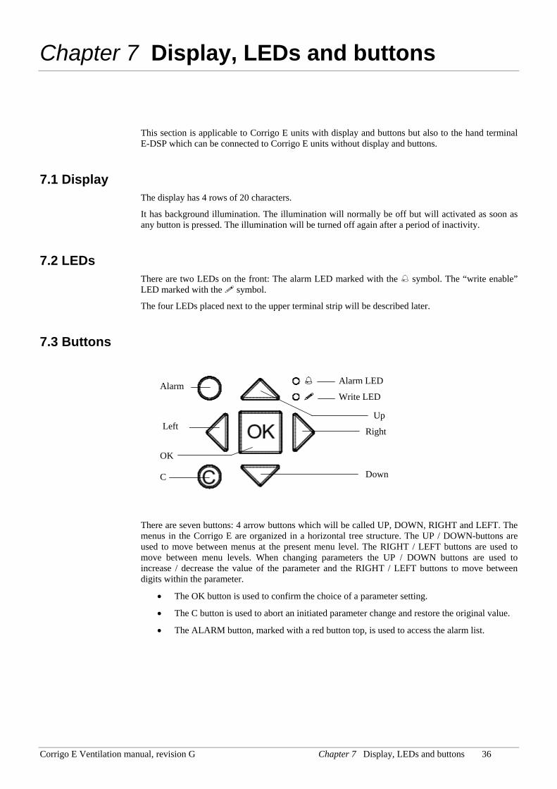
7.3 Buttons
There are seven buttons: 4 arrow buttons which will be called UP, DOWN, RIGHT and LEFT. The menus in the Corrigo E are organized in a horizontal tree structure. The UP / DOWN-buttons are used to move between menus at the present menu level. The RIGHT / LEFT buttons are used to move between menu levels. When changing parameters the UP / DOWN buttons are used to increase / decrease the value of the parameter and the RIGHT / LEFT buttons to move between digits within the parameter.
• The OK button is used to confirm the choice of a parameter setting.
• The C button is used to abort an initiated parameter change and restore the original value.
• The ALARM button, marked with a red button top, is used to access the alarm list.
Alarm LED
Write LED
Up
Right
Down
Left
Alarm
OK
C
Corrigo E Ventilation manual, revision G Chapter 7 Display, LEDs and buttons 37
7.4 Navigating the menus The start display, the display normally shown, is at the root of the menu tree.
Pressing DOWN will move you through the menu choices at this, the lowest level. UP will move you back through the choices.
To enter a higher menu level, use UP or DOWN to place the display marker opposite the menu you wish to access and press RIGHT . If you have sufficient log on privileges the display will change to the menu you have chosen.
At each level there may be several new menus through which you may move using the UP / DOWN buttons.
Sometimes there are further submenus linked to a menu or menu item. This is indicated by an arrow symbol at the right-hand edge of the display. To choose one, use RIGHT again. To back down to a lower menu level, use LEFT.
Change parameters In some menus there are parameters that can be set. This will be indicated by the LED flashing. To change a parameter, first press the OK button. If you need higher authority than you have to change the parameter, a log on menu will be displayed, see chapter 8 below. Otherwise, a cursor will appear at the first settable value. If you wish to change the value, do so by pressing the UP / DOWN buttons.
In numbers containing several digits you can move between the digits using the LEFT / RIGHT-buttons.
When the desired value is displayed press OK.
If there are further settable values displayed the cursor will automatically move to the next one.
To pass a value without changing it, press RIGHT.
To abort a change and return to the initial setting, press and hold the C-button until the cursor disappears.
Corrigo E Ventilation manual, revision G Chapter 8 Access rights 38
Chapter 8 Access rights
There are 3 different log on levels, System level which has the highest authority, Operator level and the basic “no-log on” level. System level gives full read / write access to all settings and parameters in all menus. Operator level gives read-only access to all settings and parameters and write access to all settings and parameters in all menus except Configuration. The basic level permits read-only access to all settings and parameters.
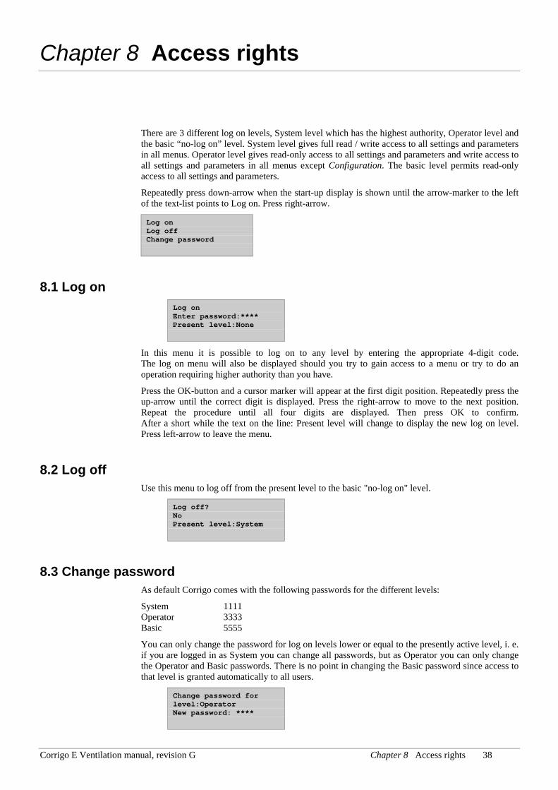
Repeatedly press down-arrow when the start-up display is shown until the arrow-marker to the left of the text-list points to Log on. Press right-arrow.
Log on Log off Change password
8.1 Log on Log on Enter password:**** Present level:None
In this menu it is possible to log on to any level by entering the appropriate 4-digit code. The log on menu will also be displayed should you try to gain access to a menu or try to do an operation requiring higher authority than you have.
Press the OK-button and a cursor marker will appear at the first digit position. Repeatedly press the up-arrow until the correct digit is displayed. Press the right-arrow to move to the next position. Repeat the procedure until all four digits are displayed. Then press OK to confirm. After a short while the text on the line: Present level will change to display the new log on level. Press left-arrow to leave the menu.
8.2 Log off Use this menu to log off from the present level to the basic "no-log on" level.
Log off? No Present level:System
8.3 Change password As default Corrigo comes with the following passwords for the different levels:
System 1111 Operator 3333 Basic 5555
You can only change the password for log on levels lower or equal to the presently active level, i. e. if you are logged in as System you can change all passwords, but as Operator you can only change the Operator and Basic passwords. There is no point in changing the Basic password since access to that level is granted automatically to all users.
Change password for level:Operator New password: ****
Corrigo E Ventilation manual, revision G Chapter 8 Access rights 39
Forgotten your password?
If the password for System has been changed and then lost, a temporary password can be obtained from Regin. This code is date dependent and only valid for one day.
Corrigo E Ventilation manual, revision G Chapter 9 Configuration 40
Chapter 9 Configuration
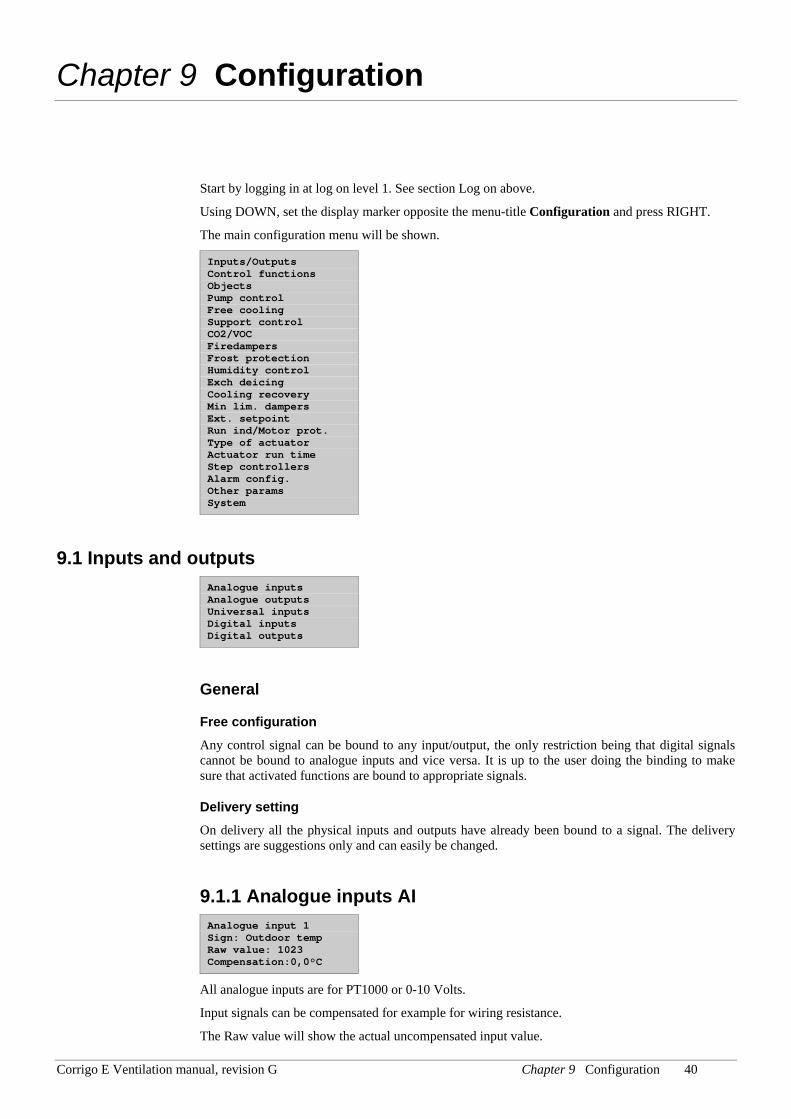
Start by logging in at log on level 1. See section Log on above.
Using DOWN, set the display marker opposite the menu-title Configuration and press RIGHT.
The main configuration menu will be shown.
Inputs/Outputs Control functions Objects Pump control Free cooling Support control CO2/VOC Firedampers Frost protection Humidity control Exch deicing Cooling recovery Min lim. dampers Ext. setpoint Run ind/Motor prot. Type of actuator Actuator run time Step controllers Alarm config. Other params System
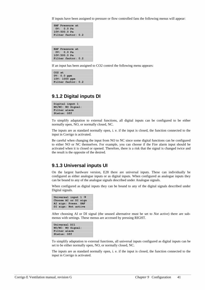
9.1 Inputs and outputs Analogue inputs Analogue outputs Universal inputs Digital inputs Digital outputs
General
Free configuration Any control signal can be bound to any input/output, the only restriction being that digital signals cannot be bound to analogue inputs and vice versa. It is up to the user doing the binding to make sure that activated functions are bound to appropriate signals.
Delivery setting On delivery all the physical inputs and outputs have already been bound to a signal. The delivery settings are suggestions only and can easily be changed.
9.1.1 Analogue inputs AI Analogue input 1 Sign: Outdoor temp Raw value: 1023 Compensation:0,0°C
All analogue inputs are for PT1000 or 0-10 Volts.
Input signals can be compensated for example for wiring resistance.
The Raw value will show the actual uncompensated input value.
Corrigo E Ventilation manual, revision G Chapter 9 Configuration 41
If inputs have been assigned to pressure or flow controlled fans the following menus will appear:
SAF Pressure at 0V: 0.0 Pa 10V:500.0 Pa Filter factor: 0.2
EAF Pressure at 0V: 0.0 Pa 10V:500.0 Pa Filter factor: 0.2
If an input has been assigned to CO2 control the following menu appears:
CO2 at 0V: 0.0 ppm 10V: 1000 ppm Filter factor: 0.2
9.1.2 Digital inputs DI Digital input 1 NO/NC: NO Signal: Filter alarm Status: Off
To simplify adaptation to external functions, all digital inputs can be configured to be either normally open, NO, or normally closed, NC.
The inputs are as standard normally open, i. e. if the input is closed, the function connected to the input in Corrigo is activated.
Be careful when changing the input from NO to NC since some digital functions can be configured to either NO or NC themselves. For example, you can choose if the Fire alarm input should be activated when it is closed or opened. Therefore, there is a risk that the signal is changed twice and the result is the opposite of the desired.
9.1.3 Universal inputs UI On the largest hardware version, E28 there are universal inputs. These can individually be configured as either analogue inputs or as digital inputs. When configured as analogue inputs they can be bound to any of the analogue signals described under Analogue signals.
When configured as digital inputs they can be bound to any of the digital signals described under Digital signals.
Universal input 1 Choose AI or DI sign AI sign: Press. SAF DI sign: Not active
After choosing AI or DI signal (the unused alternative must be set to Not active) there are sub-menus with settings. These menus are accessed by pressing RIGHT.
Universal DI1 NO/NC: NO Signal: Filter alarm Status: Off
To simplify adaptation to external functions, all universal inputs configured as digital inputs can be set to be either normally open, NO, or normally closed, NC.
The inputs are as standard normally open, i. e. if the input is closed, the function connected to the input in Corrigo is activated.
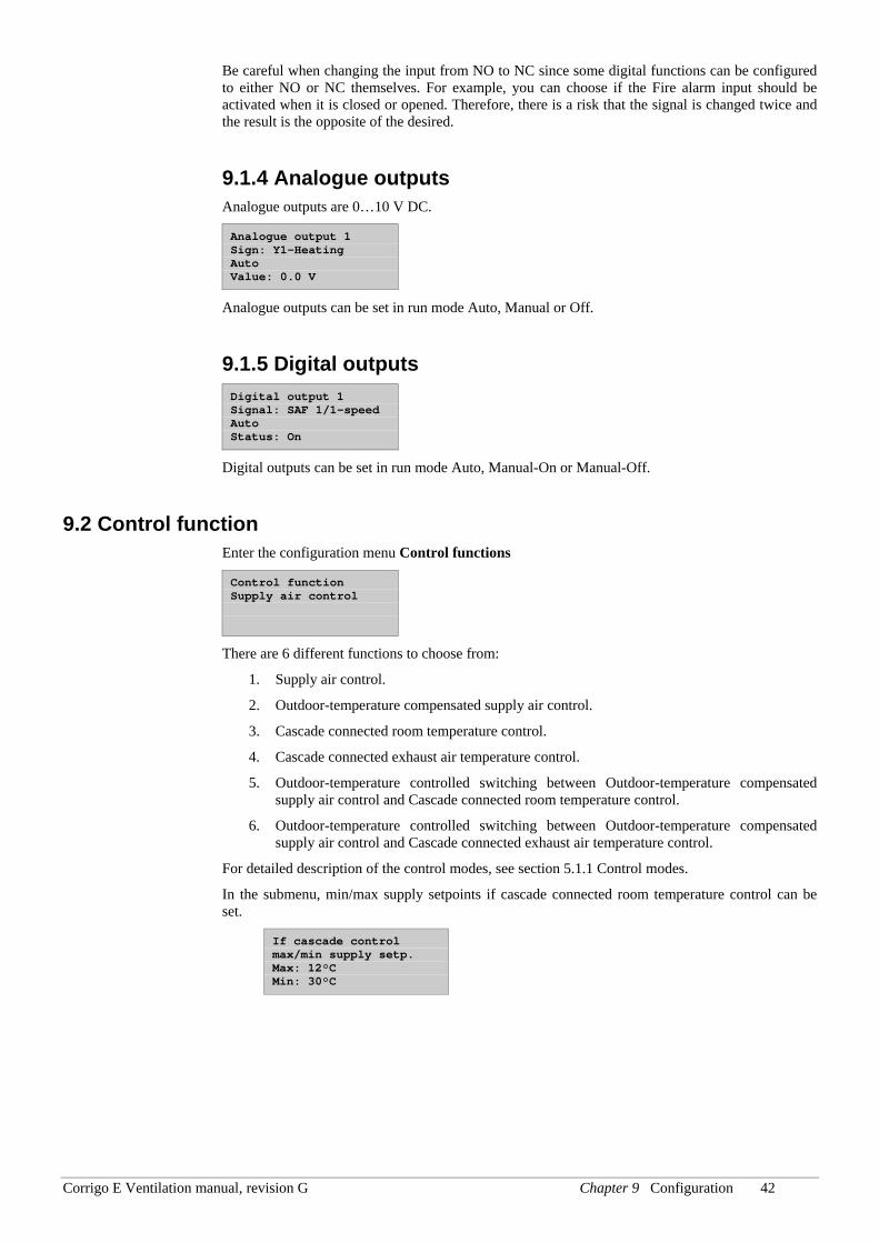
Corrigo E Ventilation manual, revision G Chapter 9 Configuration 42
Be careful when changing the input from NO to NC since some digital functions can be configured to either NO or NC themselves. For example, you can choose if the Fire alarm input should be activated when it is closed or opened. Therefore, there is a risk that the signal is changed twice and the result is the opposite of the desired.
9.1.4 Analogue outputs Analogue outputs are 0…10 V DC.
Analogue output 1 Sign: Y1-Heating Auto Value: 0.0 V
Analogue outputs can be set in run mode Auto, Manual or Off.
9.1.5 Digital outputs Digital output 1 Signal: SAF 1/1-speed Auto Status: On
Digital outputs can be set in run mode Auto, Manual-On or Manual-Off.
9.2 Control function Enter the configuration menu Control functions
Control function Supply air control
There are 6 different functions to choose from:
1. Supply air control.
2. Outdoor-temperature compensated supply air control.
3. Cascade connected room temperature control.
4. Cascade connected exhaust air temperature control.
5. Outdoor-temperature controlled switching between Outdoor-temperature compensated supply air control and Cascade connected room temperature control.
6. Outdoor-temperature controlled switching between Outdoor-temperature compensated supply air control and Cascade connected exhaust air temperature control.
For detailed description of the control modes, see section 5.1.1 Control modes.
In the submenu, min/max supply setpoints if cascade connected room temperature control can be set.
If cascade control max/min supply setp. Max: 12°C Min: 30°C
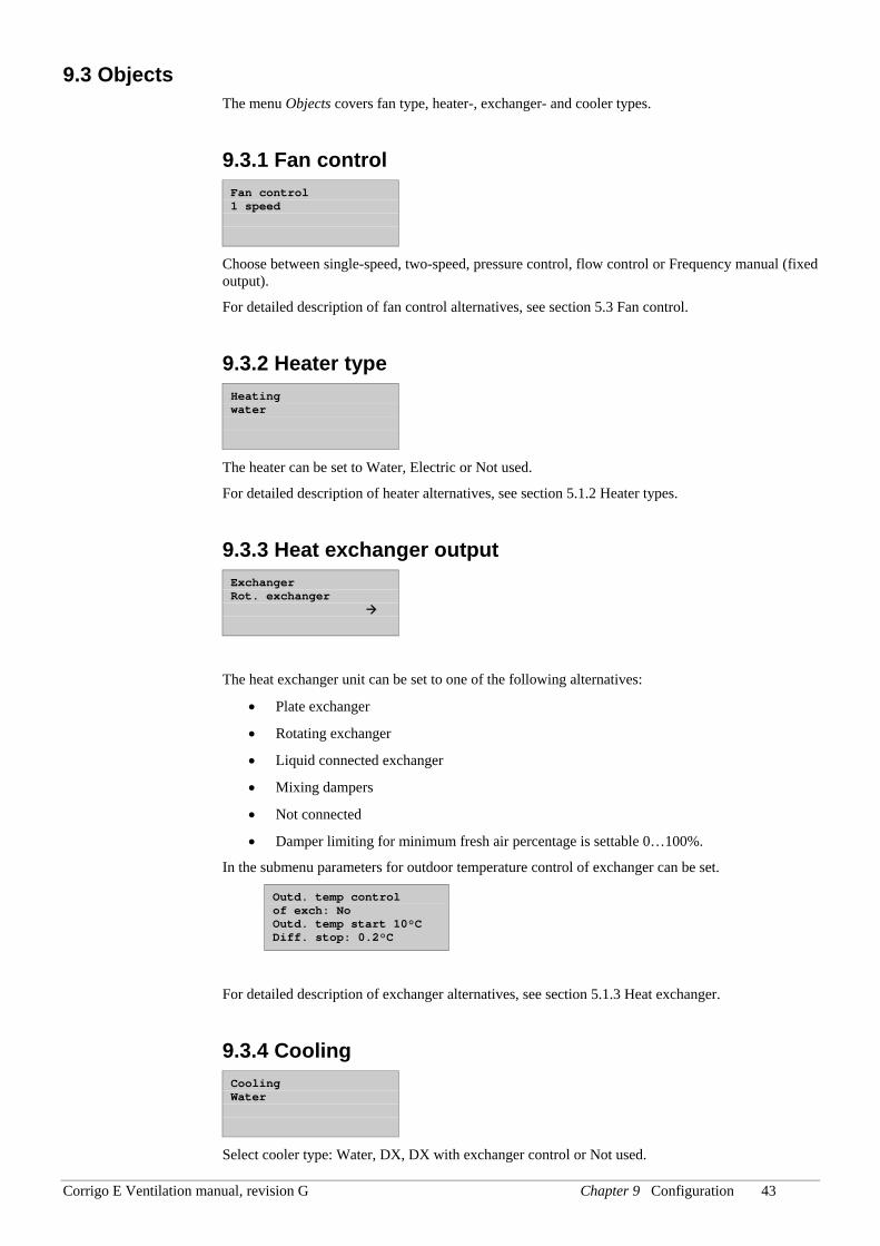
Corrigo E Ventilation manual, revision G Chapter 9 Configuration 43
9.3 Objects The menu Objects covers fan type, heater-, exchanger- and cooler types.
9.3.1 Fan control Fan control 1 speed
Choose between single-speed, two-speed, pressure control, flow control or Frequency manual (fixed output).
For detailed description of fan control alternatives, see section 5.3 Fan control.
9.3.2 Heater type Heating water
The heater can be set to Water, Electric or Not used.
For detailed description of heater alternatives, see section 5.1.2 Heater types.
9.3.3 Heat exchanger output Exchanger Rot. exchanger
The heat exchanger unit can be set to one of the following alternatives:
• Plate exchanger
• Rotating exchanger
• Liquid connected exchanger
• Mixing dampers
• Not connected
• Damper limiting for minimum fresh air percentage is settable 0…100%.
In the submenu parameters for outdoor temperature control of exchanger can be set.
Outd. temp control of exch: No Outd. temp start 10°C Diff. stop: 0.2°C
For detailed description of exchanger alternatives, see section 5.1.3 Heat exchanger.
9.3.4 Cooling Cooling Water
Select cooler type: Water, DX, DX with exchanger control or Not used.
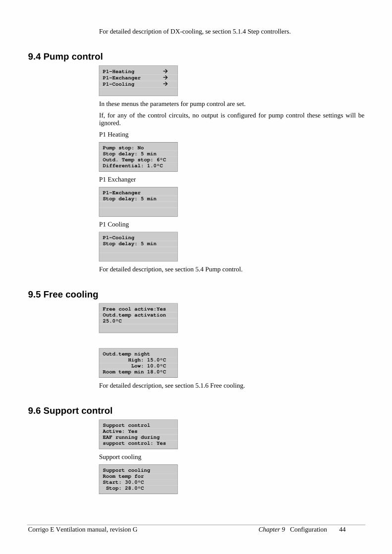
Corrigo E Ventilation manual, revision G Chapter 9 Configuration 44
For detailed description of DX-cooling, se section 5.1.4 Step controllers.
9.4 Pump control P1-Heating P1-Exchanger P1-Cooling
In these menus the parameters for pump control are set.
If, for any of the control circuits, no output is configured for pump control these settings will be ignored.
P1 Heating
Pump stop: No Stop delay: 5 min Outd. Temp stop: 6°C Differential: 1.0°C
P1 Exchanger
P1-Exchanger Stop delay: 5 min
P1 Cooling
P1-Cooling Stop delay: 5 min
For detailed description, see section 5.4 Pump control.
9.5 Free cooling Free cool active:Yes Outd.temp activation 25.0°C
Outd.temp night High: 15.0°C Low: 10.0°C Room temp min 18.0°C
For detailed description, see section 5.1.6 Free cooling.
9.6 Support control Support control Active: Yes EAF running during support control: Yes
Support cooling
Support cooling Room temp for Start: 30.0°C Stop: 28.0°C
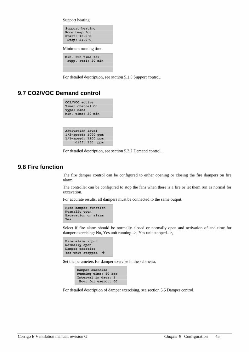
Corrigo E Ventilation manual, revision G Chapter 9 Configuration 45
Support heating
Support heating Room temp for Start: 15.0°C Stop: 21.0°C
Minimum running time
Min. run time for supp. ctrl: 20 min
For detailed description, see section 5.1.5 Support control.
9.7 CO2/VOC Demand control CO2/VOC active Timer channel On Type: Fans Min. time: 20 min
Activation level 1/2-speed: 1000 ppm 1/1-speed: 1200 ppm diff: 160 ppm
For detailed description, see section 5.3.2 Demand control.
9.8 Fire function The fire damper control can be configured to either opening or closing the fire dampers on fire alarm.
The controller can be configured to stop the fans when there is a fire or let them run as normal for excavation.
For accurate results, all dampers must be connected to the same output.
Fire damper function Normally open Excavation on alarm Yes
Select if fire alarm should be normally closed or normally open and activation of and time for damper exercising: No, Yes unit running-->, Yes unit stopped-->,
Fire alarm input Normally open Damper exercise Yes unit stopped
Set the parameters for damper exercise in the submenu.
Damper exercise Running time: 90 sec Interval in days: 1 Hour for exerc.: 00
For detailed description of damper exercising, see section 5.5 Damper control.
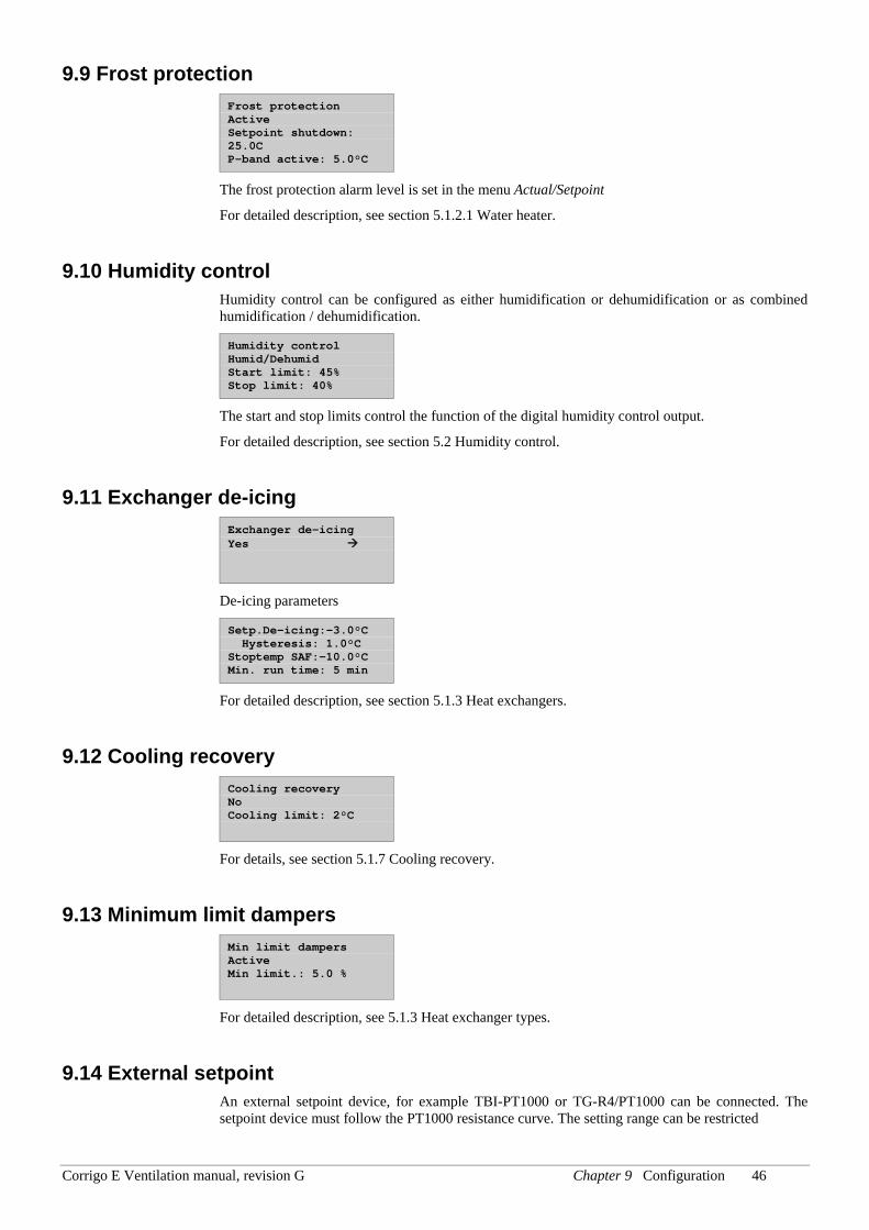
Corrigo E Ventilation manual, revision G Chapter 9 Configuration 46
9.9 Frost protection Frost protection Active Setpoint shutdown: 25.0C P-band active: 5.0°C
The frost protection alarm level is set in the menu Actual/Setpoint
For detailed description, see section 5.1.2.1 Water heater.
9.10 Humidity control Humidity control can be configured as either humidification or dehumidification or as combined humidification / dehumidification.
Humidity control Humid/Dehumid Start limit: 45% Stop limit: 40%
The start and stop limits control the function of the digital humidity control output.
For detailed description, see section 5.2 Humidity control.
9.11 Exchanger de-icing Exchanger de-icing Yes
De-icing parameters
Setp.De-icing:-3.0°C Hysteresis: 1.0°C Stoptemp SAF:-10.0°C Min. run time: 5 min
For detailed description, see section 5.1.3 Heat exchangers.
9.12 Cooling recovery Cooling recovery No Cooling limit: 2°C
For details, see section 5.1.7 Cooling recovery.
9.13 Minimum limit dampers Min limit dampers Active Min limit.: 5.0 %
For detailed description, see 5.1.3 Heat exchanger types.
9.14 External setpoint An external setpoint device, for example TBI-PT1000 or TG-R4/PT1000 can be connected. The setpoint device must follow the PT1000 resistance curve. The setting range can be restricted
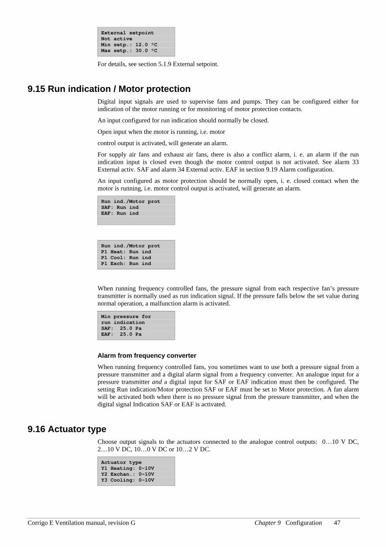
Corrigo E Ventilation manual, revision G Chapter 9 Configuration 47
External setpoint Not active Min setp.: 12.0 °C Max setp.: 30.0 °C
For details, see section 5.1.9 External setpoint.
9.15 Run indication / Motor protection Digital input signals are used to supervise fans and pumps. They can be configured either for indication of the motor running or for monitoring of motor protection contacts.
An input configured for run indication should normally be closed.
Open input when the motor is running, i.e. motor
control output is activated, will generate an alarm.
For supply air fans and exhaust air fans, there is also a conflict alarm, i. e. an alarm if the run indication input is closed even though the motor control output is not activated. See alarm 33 External activ. SAF and alarm 34 External activ. EAF in section 9.19 Alarm configuration.
An input configured as motor protection should be normally open, i. e. closed contact when the motor is running, i.e. motor control output is activated, will generate an alarm.
Run ind./Motor prot SAF: Run ind EAF: Run ind
Run ind./Motor prot P1 Heat: Run ind P1 Cool: Run ind P1 Exch: Run ind
When running frequency controlled fans, the pressure signal from each respective fan’s pressure transmitter is normally used as run indication signal. If the pressure falls below the set value during normal operation, a malfunction alarm is activated.
Min pressure for run indication SAF: 25.0 Pa EAF: 25.0 Pa
Alarm from frequency converter When running frequency controlled fans, you sometimes want to use both a pressure signal from a pressure transmitter and a digital alarm signal from a frequency converter. An analogue input for a pressure transmitter and a digital input for SAF or EAF indication must then be configured. The setting Run indication/Motor protection SAF or EAF must be set to Motor protection. A fan alarm will be activated both when there is no pressure signal from the pressure transmitter, and when the digital signal Indication SAF or EAF is activated.
9.16 Actuator type Choose output signals to the actuators connected to the analogue control outputs: 0…10 V DC, 2…10 V DC, 10…0 V DC or 10…2 V DC.
Actuator type Y1 Heating: 0-10V Y2 Exchan.: 0-10V Y3 Cooling: 0-10V
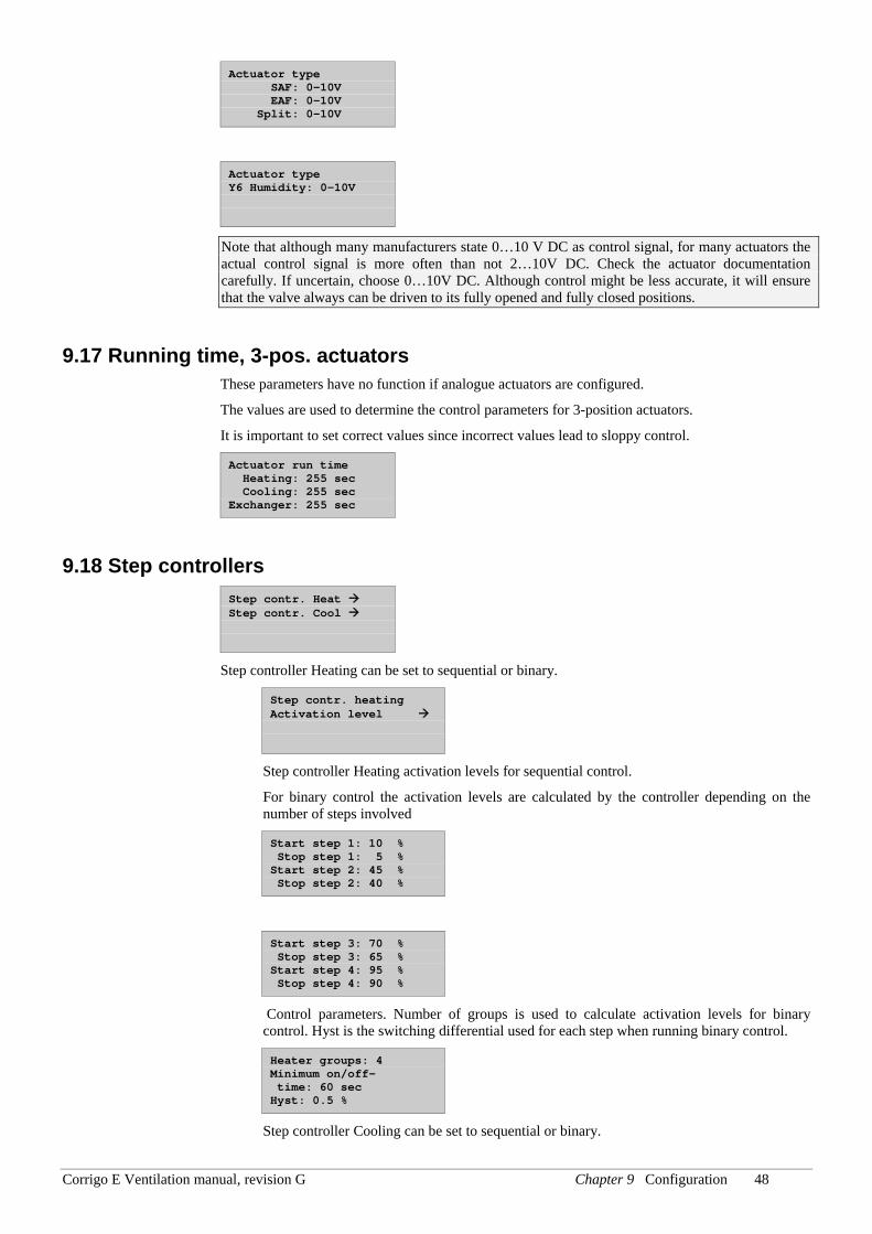
Corrigo E Ventilation manual, revision G Chapter 9 Configuration 48
Actuator type SAF: 0-10V EAF: 0-10V Split: 0-10V
Actuator type Y6 Humidity: 0-10V
Note that although many manufacturers state 0…10 V DC as control signal, for many actuators the actual control signal is more often than not 2…10V DC. Check the actuator documentation carefully. If uncertain, choose 0…10V DC. Although control might be less accurate, it will ensure that the valve always can be driven to its fully opened and fully closed positions.
9.17 Running time, 3-pos. actuators These parameters have no function if analogue actuators are configured.
The values are used to determine the control parameters for 3-position actuators.
It is important to set correct values since incorrect values lead to sloppy control.
Actuator run time Heating: 255 sec Cooling: 255 sec Exchanger: 255 sec
9.18 Step controllers Step contr. Heat Step contr. Cool
Step controller Heating can be set to sequential or binary.
Step contr. heating Activation level
Step controller Heating activation levels for sequential control.
For binary control the activation levels are calculated by the controller depending on the number of steps involved
Start step 1: 10 % Stop step 1: 5 % Start step 2: 45 % Stop step 2: 40 %
Start step 3: 70 % Stop step 3: 65 % Start step 4: 95 % Stop step 4: 90 %
Control parameters. Number of groups is used to calculate activation levels for binary control. Hyst is the switching differential used for each step when running binary control.
Heater groups: 4 Minimum on/off- time: 60 sec Hyst: 0.5 %
Step controller Cooling can be set to sequential or binary.
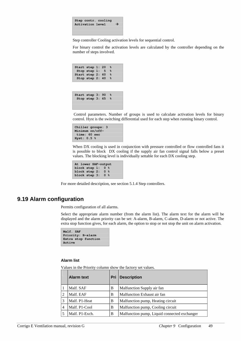
Corrigo E Ventilation manual, revision G Chapter 9 Configuration 49
Step contr. cooling Activation level
Step controller Cooling activation levels for sequential control.
For binary control the activation levels are calculated by the controller depending on the number of steps involved.
Start step 1: 20 % Stop step 1: 5 % Start step 2: 60 % Stop step 2: 40 %
Start step 3: 90 % Stop step 3: 65 %
Control parameters. Number of groups is used to calculate activation levels for binary control. Hyst is the switching differential used for each step when running binary control.
Chiller groups: 3 Minimum on/off- time: 60 sec Hyst: 0.5 %
When DX cooling is used in conjunction with pressure controlled or flow controlled fans it is possible to block DX cooling if the supply air fan control signal falls below a preset values. The blocking level is individually settable for each DX cooling step.
At lower SAF-output block step 1: 0 % block step 2: 0 % block step 3: 0 %
For more detailed description, see section 5.1.4 Step controllers.
9.19 Alarm configuration Permits configuration of all alarms.
Select the appropriate alarm number (from the alarm list). The alarm text for the alarm will be displayed and the alarm priority can be set: A-alarm, B-alarm, C-alarm, D-alarm or not active. The extra stop function gives, for each alarm, the option to stop or not stop the unit on alarm activation.
Malf. SAF Priority: B-alarm Extra stop function Active
Alarm list Values in the Priority column show the factory set values.
Alarm text Pri Description
1 Malf. SAF B Malfunction Supply air fan 2 Malf. EAF B Malfunction Exhaust air fan 3 Malf. P1-Heat B Malfunction pump, Heating circuit 4 Malf. P1-Cool B Malfunction pump, Cooling circuit 5 Malf. P1-Exch. B Malfunction pump, Liquid connected exchanger
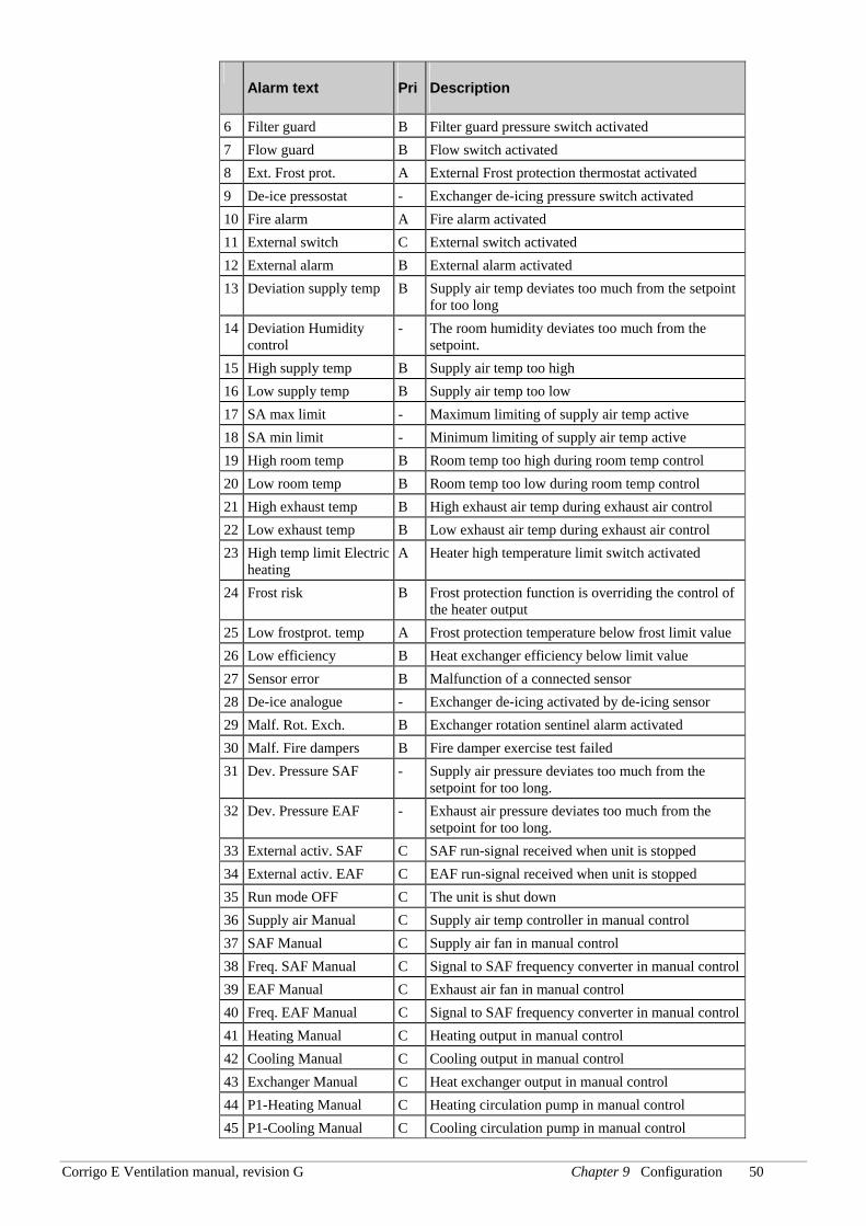
Corrigo E Ventilation manual, revision G Chapter 9 Configuration 50
Alarm text Pri Description
6 Filter guard B Filter guard pressure switch activated 7 Flow guard B Flow switch activated 8 Ext. Frost prot. A External Frost protection thermostat activated 9 De-ice pressostat - Exchanger de-icing pressure switch activated 10 Fire alarm A Fire alarm activated 11 External switch C External switch activated 12 External alarm B External alarm activated 13 Deviation supply temp B Supply air temp deviates too much from the setpoint
for too long 14 Deviation Humidity
control - The room humidity deviates too much from the
setpoint. 15 High supply temp B Supply air temp too high 16 Low supply temp B Supply air temp too low 17 SA max limit - Maximum limiting of supply air temp active 18 SA min limit - Minimum limiting of supply air temp active 19 High room temp B Room temp too high during room temp control 20 Low room temp B Room temp too low during room temp control 21 High exhaust temp B High exhaust air temp during exhaust air control 22 Low exhaust temp B Low exhaust air temp during exhaust air control 23 High temp limit Electric
heating A Heater high temperature limit switch activated
24 Frost risk B Frost protection function is overriding the control of the heater output
25 Low frostprot. temp A Frost protection temperature below frost limit value 26 Low efficiency B Heat exchanger efficiency below limit value 27 Sensor error B Malfunction of a connected sensor 28 De-ice analogue - Exchanger de-icing activated by de-icing sensor 29 Malf. Rot. Exch. B Exchanger rotation sentinel alarm activated 30 Malf. Fire dampers B Fire damper exercise test failed 31 Dev. Pressure SAF - Supply air pressure deviates too much from the
setpoint for too long. 32 Dev. Pressure EAF - Exhaust air pressure deviates too much from the
setpoint for too long. 33 External activ. SAF C SAF run-signal received when unit is stopped 34 External activ. EAF C EAF run-signal received when unit is stopped 35 Run mode OFF C The unit is shut down 36 Supply air Manual C Supply air temp controller in manual control 37 SAF Manual C Supply air fan in manual control 38 Freq. SAF Manual C Signal to SAF frequency converter in manual control39 EAF Manual C Exhaust air fan in manual control 40 Freq. EAF Manual C Signal to SAF frequency converter in manual control41 Heating Manual C Heating output in manual control 42 Cooling Manual C Cooling output in manual control 43 Exchanger Manual C Heat exchanger output in manual control 44 P1-Heating Manual C Heating circulation pump in manual control 45 P1-Cooling Manual C Cooling circulation pump in manual control
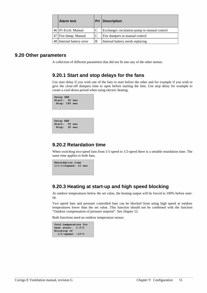
Corrigo E Ventilation manual, revision G Chapter 9 Configuration 51
Alarm text Pri Description
46 P1-Exch. Manual C Exchanger circulation pump in manual control 47 Fire damp. Manual C Fire dampers in manual control 48 Internal battery error B Internal battery needs replacing
9.20 Other parameters A collection of different parameters that did not fit into any of the other menus.
9.20.1 Start and stop delays for the fans Use start delay if you wish one of the fans to start before the other and for example if you wish to give the close-off dampers time to open before starting the fans. Use stop delay for example to create a cool-down period when using electric heating.
Delay SAF Start: 30 sec Stop: 180 sec
Delay EAF Start: 30 sec Stop: 30 sec
9.20.2 Retardation time When switching two-speed fans from 1/1-speed to 1/2-speed there is a settable retardation time. The same time applies to both fans.
Retardation time 1/1-1/2speed: 10 sec
9.20.3 Heating at start-up and high speed blocking At outdoor temperatures below the set value, the heating output will be forced to 100% before start-up.
Two speed fans and pressure controlled fans can be blocked from using high speed at outdoor temperatures lower than the set value. This function should not be combined with the function ”Outdoor compensation of pressure setpoint”. See chapter 12.
Both functions need an outdoor temperature sensor.
Outd.temperature for heat start: 3.0°C Blocking of 1/1-speed: -10°C
Corrigo E Ventilation manual, revision G Chapter 9 Configuration 52
9.20.4 Crosswise interlock between fans Crosswise interlock means that if one of the fans stops running, the other fan will automatically stop as well.
Crosswise interlock between SAF and EAF No
9.20.5 Exchanger to 100% at start and alarm delay at start To minimise the risk of freeze-up problems, the heat exchanger can be forced to maximum capacity for the set time at start-up.
To eliminate the risk of, for example, fan pressure alarms at start-up, all alarm functions can be suppressed for the set time.
Exch 100% at start 60 sec Alarm delay at start 60 sec
9.20.6 Split settings Splits the Controller output (HCOut) between the analogue temperature control output signals Y1, Y2 and Y3 for Heating, Heat exchanger and Cooling.
To create a neutral zone, leave a percentage gap between sequences.
The set P-band for the supply air controller is for the whole Controller output. This means that the P-band for each sequence is proportionate to the split percentage values given to sequences.
Example: P-band for the supply air controller is set to 25°C. The split is set so that cooling gets 0…20% = 20%, the exchanger gets 30…50% = 20% and the heater gets 50…100% = 50%. The individual P-bands will then be:
Cooling: 20% of 25°C = 5°C
Exchanger: 20% of 25°C = 5°C
Heater: 50% of 25°C = 12.5°C
The remaining 2.5°C are the neutral zone between cooling and exchanger.
Split settings Cooling 0% at HCOut= 20% 100% at HCOut= 0%
Split settings Exchanger 0% at HCOut= 50% 100% at HCOut= 30%
Split settings Heating 0% at HCOut= 50% 100% at HCOut=100%
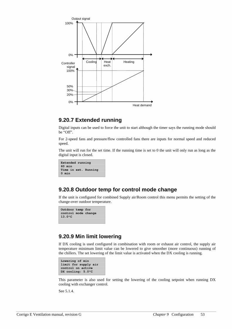
Corrigo E Ventilation manual, revision G Chapter 9 Configuration 53
Controller signal
HeatingHeat exch.
Cooling
Output signal
0%
100%
0%
100%
Heat demand
20%
50% 30%
9.20.7 Extended running Digital inputs can be used to force the unit to start although the timer says the running mode should be “Off”.
For 2-speed fans and pressure/flow controlled fans there are inputs for normal speed and reduced speed.
The unit will run for the set time. If the running time is set to 0 the unit will only run as long as the digital input is closed.
Extended running 60 min Time in ext. Running 0 min
9.20.8 Outdoor temp for control mode change If the unit is configured for combined Supply air/Room control this menu permits the setting of the change-over outdoor temperature.
Outdoor temp for control mode change 13.0°C
9.20.9 Min limit lowering If DX cooling is used configured in combination with room or exhaust air control, the supply air temperature minimum limit value can be lowered to give smoother (more continuous) running of the chillers. The set lowering of the limit value is activated when the DX cooling is running.
Lowering of min limit for supply air control on active DX cooling: 5.0°C
This parameter is also used for setting the lowering of the cooling setpoint when running DX cooling with exchanger control.
See 5.1.4.
Corrigo E Ventilation manual, revision G Chapter 9 Configuration 54
9.20.10 Split of optional temp sequence Any one of the temperature control output sequences Y1, Y2 and Y3 can be split, for example to control two heating valves in sequence. The split is always even 50/50 which means that each part of the split will have half the part of the P-band assigned to the output. An analogue output must be assigned to the output signal “Split”. On increasing output demand, the regular output is always run first and then the split output.
Split optional temperature sequence Y1 Y2 Y3 No split
9.20.11 Flow control Flow control factors K-constant: 0.28 X-constant: 0.50
For more detailed description, see section 5.3.1 Pressure control.
9.20.12 Blocking the DX cooling on low outdoor temp At outdoor temperatures below the set value, DX cooling will not be activated. The function has a 1 K hysteresis, i.e. if DX cooling is blocked, the outdoor temperature must rise to 1K above the set value for the cooling to be activated again.
Blocking the DX-cooling at lower outdoor temperature 13.0 °C
9.20.13 Blocking the DX cooling on cooling pump alarm DX cooling can be blocked on activation of the cooling pump alarm.
Blocking the DX- cooling if alarm ”Run error P1- cooler”:No
9.20.14 Fast stop on overheating If this function is active, the fans will immediately be stopped when there is an overheating alarm, regardless of the set cool-down time.
Fast stop if alarm Electric heating is overheated: No
Corrigo E Ventilation manual, revision G Chapter 9 Configuration 55
9.21 System
9.21.1 Change language Use this menu to change the display language.
Choose language English
9.21.2 Choose start display; the text normally shown on the display There are 5 different to choose from.
Type 1 The text on the first line can be changed using Corrigo E-tool.
The second line shows date and time.
The third line shows the present running status.
The fourth line shows the present temperature setpoint and actual values.
Vent unit 18 PX 2004-03-15 11:28 System: Running Sp:22.0°C Act:21.8°C
Type 2 The first line shows date and time.
The second line shows the present running status.
The third line shows the present temperature setpoint and actual values.
The fourth line shows present temperature control output values.
2004-03-15 11:28 System: Running Sp:22.0°C Act:21.8°C Y1:0% Y2:93% Y3:0%
Type 3 The first line shows date and time.
The second line shows the present running status.
The third line shows the present temperature setpoint and actual values.
The fourth line shows present SAF and EAF pressures.
2004-03-15 11:28 System: Running Sp:22.0°C Act:21.8°C SAF:1100PaEAF:1050Pa
Type 4 The text on the first line can be changed using Corrigo E-tool.
The second line shows date and time.
The third line shows the present running status.
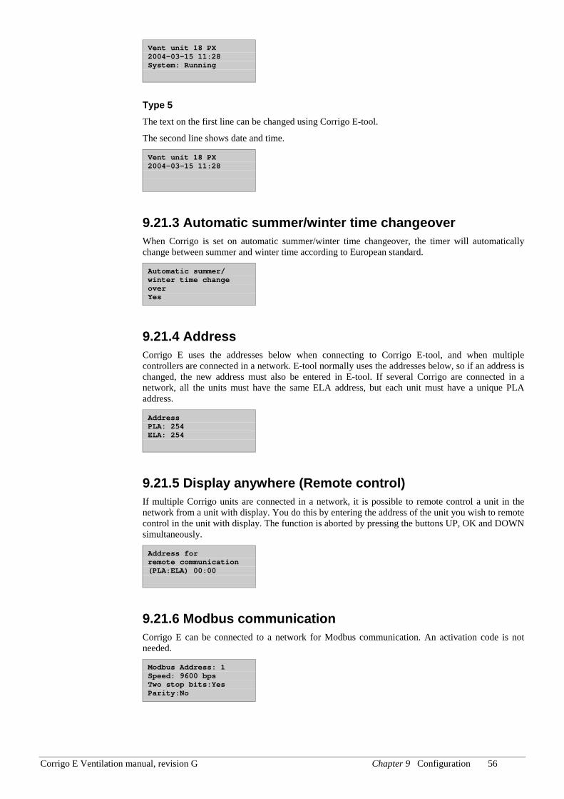
Corrigo E Ventilation manual, revision G Chapter 9 Configuration 56
Vent unit 18 PX 2004-03-15 11:28 System: Running
Type 5 The text on the first line can be changed using Corrigo E-tool.
The second line shows date and time.
Vent unit 18 PX 2004-03-15 11:28
9.21.3 Automatic summer/winter time changeover When Corrigo is set on automatic summer/winter time changeover, the timer will automatically change between summer and winter time according to European standard.
Automatic summer/ winter time change over Yes
9.21.4 Address Corrigo E uses the addresses below when connecting to Corrigo E-tool, and when multiple controllers are connected in a network. E-tool normally uses the addresses below, so if an address is changed, the new address must also be entered in E-tool. If several Corrigo are connected in a network, all the units must have the same ELA address, but each unit must have a unique PLA address.
Address PLA: 254 ELA: 254
9.21.5 Display anywhere (Remote control) If multiple Corrigo units are connected in a network, it is possible to remote control a unit in the network from a unit with display. You do this by entering the address of the unit you wish to remote control in the unit with display. The function is aborted by pressing the buttons UP, OK and DOWN simultaneously.
Address for remote communication (PLA:ELA) 00:00
9.21.6 Modbus communication Corrigo E can be connected to a network for Modbus communication. An activation code is not needed.
Modbus Address: 1 Speed: 9600 bps Two stop bits:Yes Parity:No
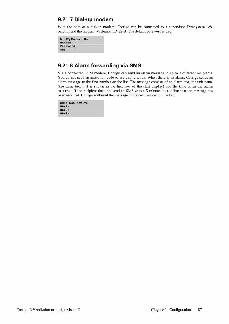
Corrigo E Ventilation manual, revision G Chapter 9 Configuration 57
9.21.7 Dial-up modem With the help of a dial-up modem, Corrigo can be connected to a supervisor Exo-system. We recommend the modem Westermo TD-32-B. The default password is exo.
DialUpModem: No Number: Password: exo
9.21.8 Alarm forwarding via SMS Via a connected GSM modem, Corrigo can send an alarm message to up to 3 different recipients. You do not need an activation code to use this function. When there is an alarm, Corrigo sends an alarm message to the first number on the list. The message consists of an alarm text, the unit name (the same text that is shown in the first row of the start display) and the time when the alarm occurred. If the recipient does not send an SMS within 5 minutes to confirm that the message has been received, Corrigo will send the message to the next number on the list.
SMS: Not Active Nbr1: Nbr2: Nbr3:
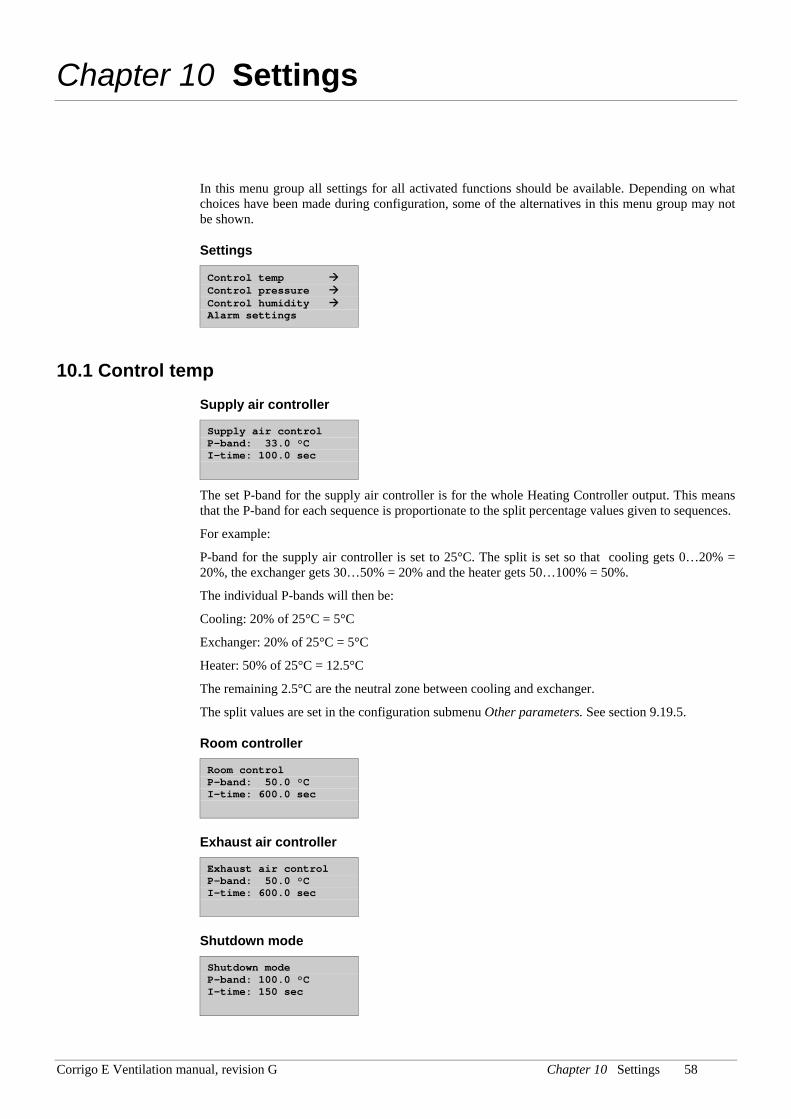
Corrigo E Ventilation manual, revision G Chapter 10 Settings 58
Chapter 10 Settings
In this menu group all settings for all activated functions should be available. Depending on what choices have been made during configuration, some of the alternatives in this menu group may not be shown.
Settings
Control temp Control pressure Control humidity Alarm settings
10.1 Control temp
Supply air controller
Supply air control P-band: 33.0 °C I-time: 100.0 sec
The set P-band for the supply air controller is for the whole Heating Controller output. This means that the P-band for each sequence is proportionate to the split percentage values given to sequences.
For example:
P-band for the supply air controller is set to 25°C. The split is set so that cooling gets 0…20% = 20%, the exchanger gets 30…50% = 20% and the heater gets 50…100% = 50%.
The individual P-bands will then be:
Cooling: 20% of 25°C = 5°C
Exchanger: 20% of 25°C = 5°C
Heater: 50% of 25°C = 12.5°C
The remaining 2.5°C are the neutral zone between cooling and exchanger.
The split values are set in the configuration submenu Other parameters. See section 9.19.5.
Room controller
Room control P-band: 50.0 °C I-time: 600.0 sec
Exhaust air controller
Exhaust air control P-band: 50.0 °C I-time: 600.0 sec
Shutdown mode
Shutdown mode P-band: 100.0 °C I-time: 150 sec
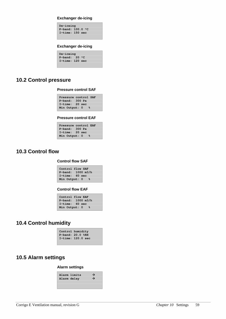
Corrigo E Ventilation manual, revision G Chapter 10 Settings 59
Exchanger de-icing
De-iceing P-band: 100.0 °C I-time: 150 sec
Exchanger de-icing
De-iceing P-band: 20 °C I-time: 120 sec
10.2 Control pressure Pressure control SAF
Pressure control SAF P-band: 300 Pa I-time: 20 sec Min Output: 0 %
Pressure control EAF
Pressure control EAF P-band: 300 Pa I-time: 20 sec Min Output: 0 %
10.3 Control flow
Control flow SAF
Control flow SAF P-band: 1000 m3/h I-time: 60 sec Min Output: 0 %
Control flow EAF
Control flow EAF P-band: 1000 m3/h I-time: 60 sec Min Output: 0 %
10.4 Control humidity Control humidity P-band: 20.0 %RH I-time: 120.0 sec
10.5 Alarm settings Alarm settings
Alarm limits Alarm delay
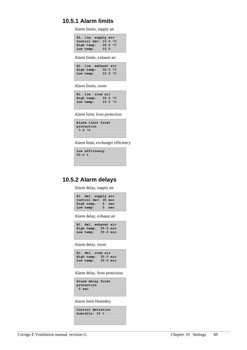
Corrigo E Ventilation manual, revision G Chapter 10 Settings 60
10.5.1 Alarm limits Alarm limits, supply air
Al. lim. supply air Control dev: 10.0 °C High temp: 30.0 °C Low temp: 10.0
Alarm limits, exhaust air
Al. lim. exhaust air High temp: 30.0 °C Low temp: 10.0 °C
Alarm limits, room
Al. lim. room air High temp: 30.0 °C Low temp: 10.0 °C
Alarm limit, frost protection
Alarm limit frost protection 7.0 °C
Alarm limit, exchanger efficiency
Low efficiency 50.0 %
10.5.2 Alarm delays Alarm delay, supply air
Al. del. supply air Control dev: 30 min High temp: 5 sec Low temp: 5 sec
Alarm delay, exhaust air
Al. del. exhaust air High temp: 30.0 min Low temp: 30.0 min
Alarm delay, room
Al. del. room air High temp: 30.0 min Low temp: 30.0 min
Alarm delay, frost protection
Alarm delay frost protection 0 sec
Alarm limit Humidity
Control deviation humidity: 10 %
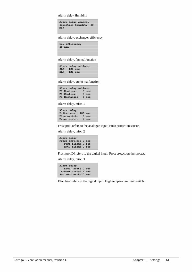
Corrigo E Ventilation manual, revision G Chapter 10 Settings 61
Alarm delay Humidity
Alarm delay control deviation humidity: 30 min
Alarm delay, exchanger efficiency
Low efficiency 30 min
Alarm delay, fan malfunction
Alarm delay malfunc. SAF: 120 sec EAF: 120 sec
Alarm delay, pump malfunction
Alarm delay malfunc. P1-Heating: 5 sec P1-Cooling: 5 sec P1-Exchanger: 5 sec
Alarm delay, misc. 1
Alarm delay Filter mon.: 180 sec Flow switch: 5 sec Frost prot.: 0 sec
Frost prot. refers to the analogue input: Frost protection sensor.
Alarm delay, misc. 2
Alarm delay Frost prot.DI: 0 sec Fire alarm: 0 sec Ext. alarm: 0 sec
Frost prot DI refers to the digital input: Frost protection thermostat.
Alarm delay, misc. 3
Alarm delay Elec. heat: 0 sec Sensor error: 5 sec Rot.sent.exch:20 sec
Elec. heat refers to the digital input: High temperature limit switch.
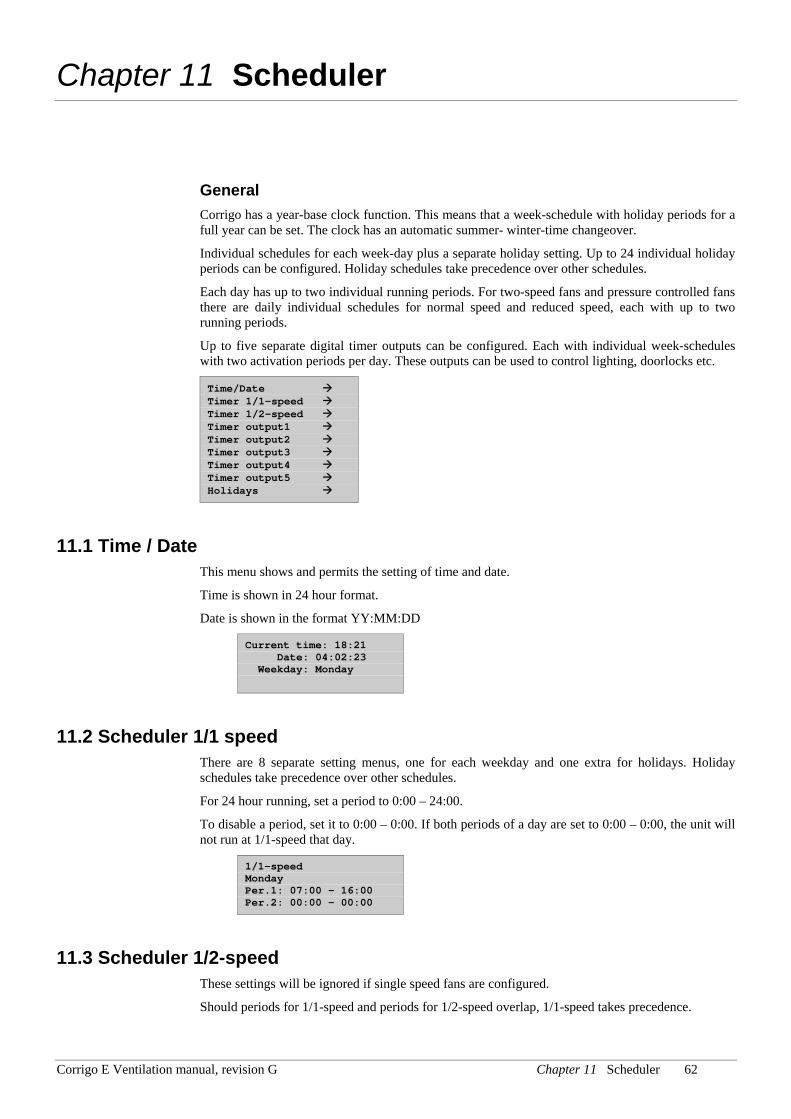
Corrigo E Ventilation manual, revision G Chapter 11 Scheduler 62
Chapter 11 Scheduler
General Corrigo has a year-base clock function. This means that a week-schedule with holiday periods for a full year can be set. The clock has an automatic summer- winter-time changeover.
Individual schedules for each week-day plus a separate holiday setting. Up to 24 individual holiday periods can be configured. Holiday schedules take precedence over other schedules.
Each day has up to two individual running periods. For two-speed fans and pressure controlled fans there are daily individual schedules for normal speed and reduced speed, each with up to two running periods.
Up to five separate digital timer outputs can be configured. Each with individual week-schedules with two activation periods per day. These outputs can be used to control lighting, doorlocks etc.
Time/Date Timer 1/1-speed Timer 1/2-speed Timer output1 Timer output2 Timer output3 Timer output4 Timer output5 Holidays
11.1 Time / Date This menu shows and permits the setting of time and date.
Time is shown in 24 hour format.
Date is shown in the format YY:MM:DD
Current time: 18:21 Date: 04:02:23 Weekday: Monday
11.2 Scheduler 1/1 speed There are 8 separate setting menus, one for each weekday and one extra for holidays. Holiday schedules take precedence over other schedules.
For 24 hour running, set a period to 0:00 – 24:00.
To disable a period, set it to 0:00 – 0:00. If both periods of a day are set to 0:00 – 0:00, the unit will not run at 1/1-speed that day.
1/1-speed Monday Per.1: 07:00 – 16:00 Per.2: 00:00 - 00:00
11.3 Scheduler 1/2-speed These settings will be ignored if single speed fans are configured.
Should periods for 1/1-speed and periods for 1/2-speed overlap, 1/1-speed takes precedence.
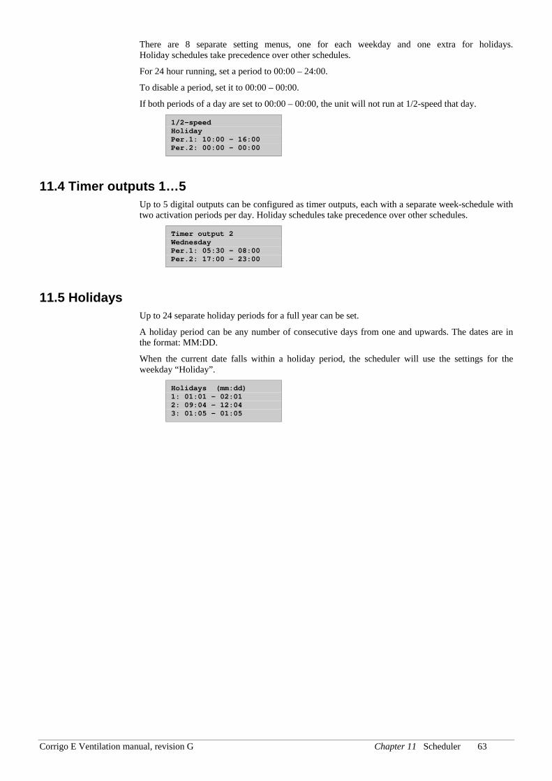
Corrigo E Ventilation manual, revision G Chapter 11 Scheduler 63
There are 8 separate setting menus, one for each weekday and one extra for holidays. Holiday schedules take precedence over other schedules.
For 24 hour running, set a period to 00:00 – 24:00.
To disable a period, set it to 00:00 – 00:00.
If both periods of a day are set to 00:00 – 00:00, the unit will not run at 1/2-speed that day.
1/2-speed Holiday Per.1: 10:00 – 16:00 Per.2: 00:00 - 00:00
11.4 Timer outputs 1…5 Up to 5 digital outputs can be configured as timer outputs, each with a separate week-schedule with two activation periods per day. Holiday schedules take precedence over other schedules.
Timer output 2 Wednesday Per.1: 05:30 – 08:00 Per.2: 17:00 – 23:00
11.5 Holidays Up to 24 separate holiday periods for a full year can be set.
A holiday period can be any number of consecutive days from one and upwards. The dates are in the format: MM:DD.
When the current date falls within a holiday period, the scheduler will use the settings for the weekday “Holiday”.
Holidays (mm:dd) 1: 01:01 - 02:01 2: 09:04 – 12:04 3: 01:05 - 01:05
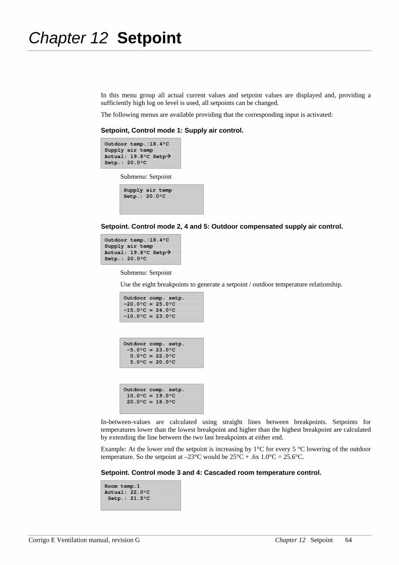
Corrigo E Ventilation manual, revision G Chapter 12 Setpoint 64
Chapter 12 Setpoint
In this menu group all actual current values and setpoint values are displayed and, providing a sufficiently high log on level is used, all setpoints can be changed.
The following menus are available providing that the corresponding input is activated:
Setpoint, Control mode 1: Supply air control.
Outdoor temp.:18.4°C Supply air temp Actual: 19.8°C Setp Setp.: 20.0°C
Submenu: Setpoint
Supply air temp Setp.: 20.0°C
Setpoint. Control mode 2, 4 and 5: Outdoor compensated supply air control.
Outdoor temp.:18.4°C Supply air temp Actual: 19.8°C Setp Setp.: 20.0°C
Submenu: Setpoint
Use the eight breakpoints to generate a setpoint / outdoor temperature relationship.
Outdoor comp. setp. -20.0°C = 25.0°C -15.0°C = 24.0°C -10.0°C = 23.0°C
Outdoor comp. setp. -5.0°C = 23.0°C 0.0°C = 22.0°C 5.0°C = 20.0°C
Outdoor comp. setp. 10.0°C = 19.0°C 20.0°C = 18.0°C
In-between-values are calculated using straight lines between breakpoints. Setpoints for temperatures lower than the lowest breakpoint and higher than the highest breakpoint are calculated by extending the line between the two last breakpoints at either end.
Example: At the lower end the setpoint is increasing by 1°C for every 5 °C lowering of the outdoor temperature. So the setpoint at –23°C would be 25°C + .6x 1.0°C = 25.6°C.
Setpoint. Control mode 3 and 4: Cascaded room temperature control.
Room temp.1 Actual: 22.0°C Setp.: 21.5°C
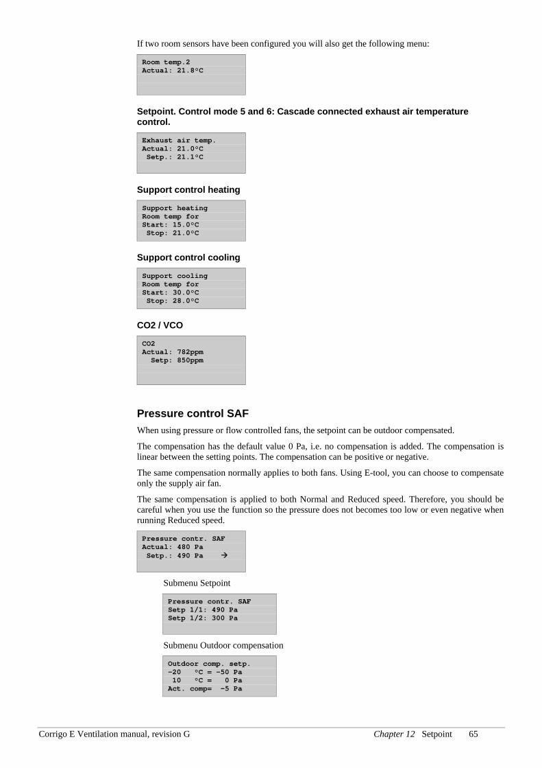
Corrigo E Ventilation manual, revision G Chapter 12 Setpoint 65
If two room sensors have been configured you will also get the following menu:
Room temp.2 Actual: 21.8°C
Setpoint. Control mode 5 and 6: Cascade connected exhaust air temperature control.
Exhaust air temp. Actual: 21.0°C Setp.: 21.1°C
Support control heating
Support heating Room temp for Start: 15.0°C Stop: 21.0°C
Support control cooling
Support cooling Room temp for Start: 30.0°C Stop: 28.0°C
CO2 / VCO
CO2 Actual: 782ppm Setp: 850ppm
Pressure control SAF When using pressure or flow controlled fans, the setpoint can be outdoor compensated.
The compensation has the default value 0 Pa, i.e. no compensation is added. The compensation is linear between the setting points. The compensation can be positive or negative.
The same compensation normally applies to both fans. Using E-tool, you can choose to compensate only the supply air fan.
The same compensation is applied to both Normal and Reduced speed. Therefore, you should be careful when you use the function so the pressure does not becomes too low or even negative when running Reduced speed.
Pressure contr. SAF Actual: 480 Pa Setp.: 490 Pa
Submenu Setpoint
Pressure contr. SAF Setp 1/1: 490 Pa Setp 1/2: 300 Pa
Submenu Outdoor compensation
Outdoor comp. setp. -20 °C = -50 Pa 10 °C = 0 Pa Act. comp= -5 Pa
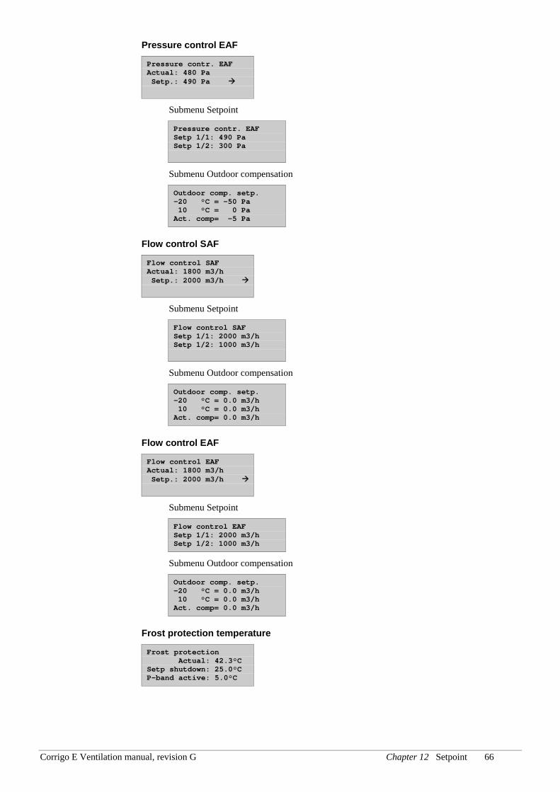
Corrigo E Ventilation manual, revision G Chapter 12 Setpoint 66
Pressure control EAF
Pressure contr. EAF Actual: 480 Pa Setp.: 490 Pa
Submenu Setpoint
Pressure contr. EAF Setp 1/1: 490 Pa Setp 1/2: 300 Pa
Submenu Outdoor compensation
Outdoor comp. setp. -20 °C = -50 Pa 10 °C = 0 Pa Act. comp= -5 Pa
Flow control SAF
Flow control SAF Actual: 1800 m3/h Setp.: 2000 m3/h
Submenu Setpoint
Flow control SAF Setp 1/1: 2000 m3/h Setp 1/2: 1000 m3/h
Submenu Outdoor compensation
Outdoor comp. setp. -20 °C = 0.0 m3/h 10 °C = 0.0 m3/h Act. comp= 0.0 m3/h
Flow control EAF
Flow control EAF Actual: 1800 m3/h Setp.: 2000 m3/h
Submenu Setpoint
Flow control EAF Setp 1/1: 2000 m3/h Setp 1/2: 1000 m3/h
Submenu Outdoor compensation
Outdoor comp. setp. -20 °C = 0.0 m3/h 10 °C = 0.0 m3/h Act. comp= 0.0 m3/h
Frost protection temperature
Frost protection Actual: 42.3°C Setp shutdown: 25.0°C P-band active: 5.0°C
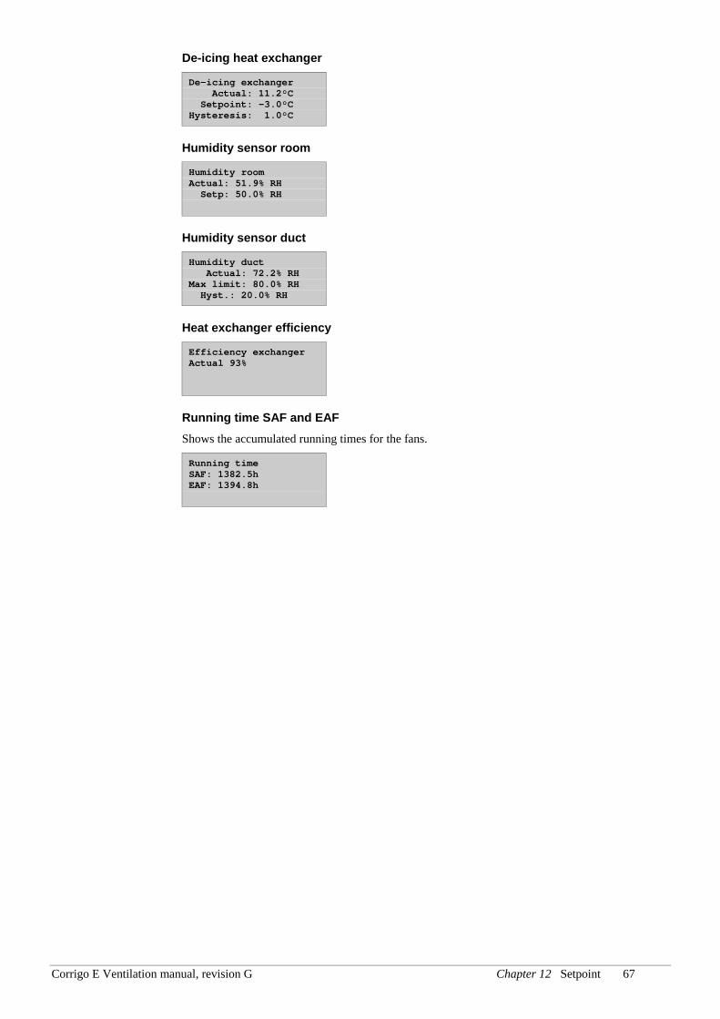
Corrigo E Ventilation manual, revision G Chapter 12 Setpoint 67
De-icing heat exchanger
De-icing exchanger Actual: 11.2°C Setpoint: -3.0°C Hysteresis: 1.0°C
Humidity sensor room
Humidity room Actual: 51.9% RH Setp: 50.0% RH
Humidity sensor duct
Humidity duct Actual: 72.2% RH Max limit: 80.0% RH Hyst.: 20.0% RH
Heat exchanger efficiency
Efficiency exchanger Actual 93%
Running time SAF and EAF Shows the accumulated running times for the fans.
Running time SAF: 1382.5h EAF: 1394.8h
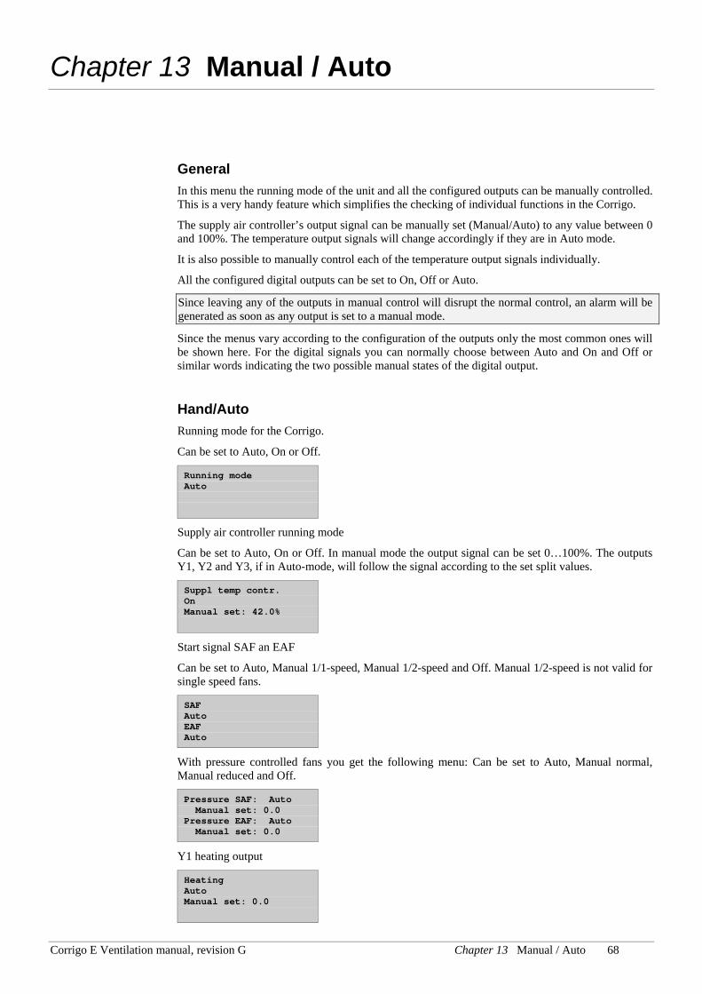
Corrigo E Ventilation manual, revision G Chapter 13 Manual / Auto 68
Chapter 13 Manual / Auto
General In this menu the running mode of the unit and all the configured outputs can be manually controlled. This is a very handy feature which simplifies the checking of individual functions in the Corrigo.
The supply air controller’s output signal can be manually set (Manual/Auto) to any value between 0 and 100%. The temperature output signals will change accordingly if they are in Auto mode.
It is also possible to manually control each of the temperature output signals individually.
All the configured digital outputs can be set to On, Off or Auto.
Since leaving any of the outputs in manual control will disrupt the normal control, an alarm will be generated as soon as any output is set to a manual mode.
Since the menus vary according to the configuration of the outputs only the most common ones will be shown here. For the digital signals you can normally choose between Auto and On and Off or similar words indicating the two possible manual states of the digital output.
Hand/Auto Running mode for the Corrigo.
Can be set to Auto, On or Off.
Running mode Auto
Supply air controller running mode
Can be set to Auto, On or Off. In manual mode the output signal can be set 0…100%. The outputs Y1, Y2 and Y3, if in Auto-mode, will follow the signal according to the set split values.
Suppl temp contr. On Manual set: 42.0%
Start signal SAF an EAF
Can be set to Auto, Manual 1/1-speed, Manual 1/2-speed and Off. Manual 1/2-speed is not valid for single speed fans.
SAF Auto EAF Auto
With pressure controlled fans you get the following menu: Can be set to Auto, Manual normal, Manual reduced and Off.
Pressure SAF: Auto Manual set: 0.0 Pressure EAF: Auto Manual set: 0.0
Y1 heating output
Heating Auto Manual set: 0.0
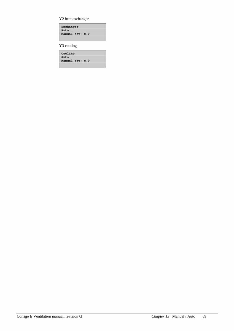
Corrigo E Ventilation manual, revision G Chapter 13 Manual / Auto 69
Y2 heat exchanger
Exchanger Auto Manual set: 0.0
Y3 cooling
Cooling Auto Manual set: 0.0
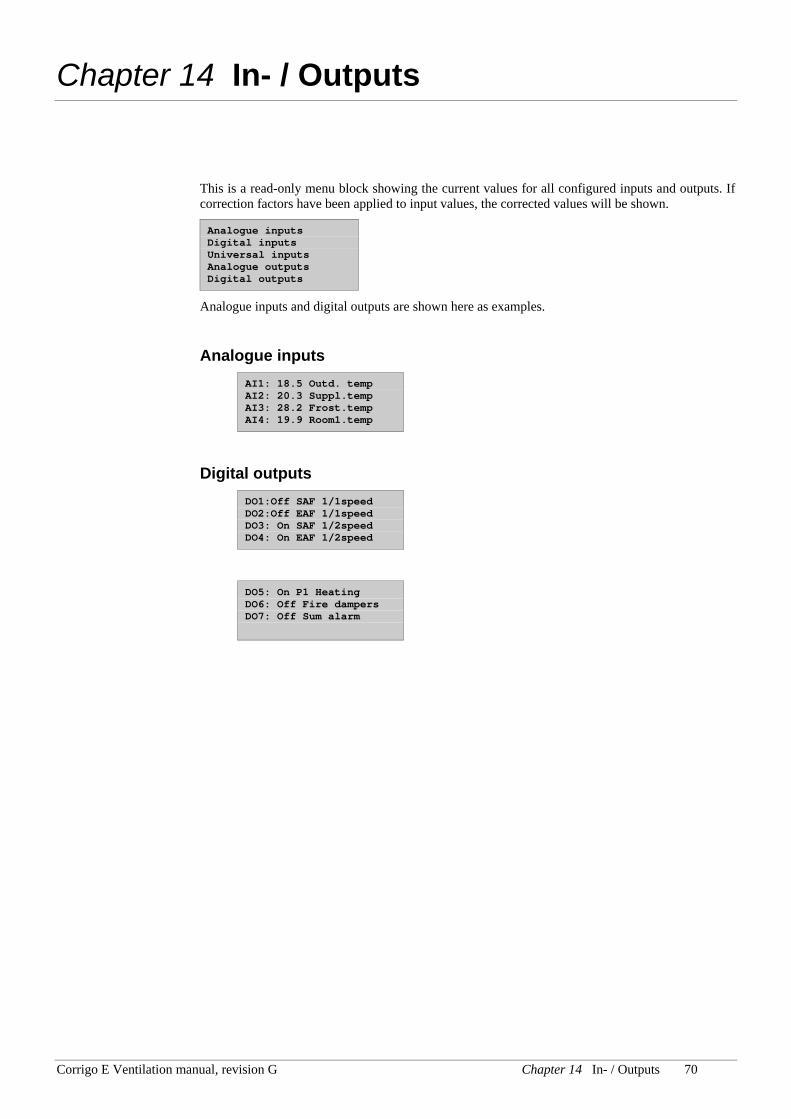
Corrigo E Ventilation manual, revision G Chapter 14 In- / Outputs 70
Chapter 14 In- / Outputs
This is a read-only menu block showing the current values for all configured inputs and outputs. If correction factors have been applied to input values, the corrected values will be shown.
Analogue inputs Digital inputs Universal inputs Analogue outputs Digital outputs
Analogue inputs and digital outputs are shown here as examples.
Analogue inputs AI1: 18.5 Outd. temp AI2: 20.3 Suppl.temp AI3: 28.2 Frost.temp AI4: 19.9 Room1.temp
Digital outputs DO1:Off SAF 1/1speed DO2:Off EAF 1/1speed DO3: On SAF 1/2speed DO4: On EAF 1/2speed
DO5: On P1 Heating DO6: Off Fire dampers DO7: Off Sum alarm
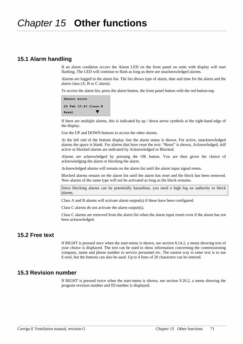
Corrigo E Ventilation manual, revision G Chapter 15 Other functions 71
Chapter 15 Other functions
15.1 Alarm handling If an alarm condition occurs the Alarm LED on the front panel on units with display will start flashing. The LED will continue to flash as long as there are unacknowledged alarms.
Alarms are logged in the alarm list. The list shows type of alarm, date and time for the alarm and the alarm class (A, B or C alarm).
To access the alarm list, press the alarm button, the front panel button with the red button-top.
Sensor error 24 Feb 10:43 Class:B
Reset
If there are multiple alarms, this is indicated by up / down arrow symbols at the right-hand edge of the display.
Use the UP and DOWN buttons to access the other alarms.
At the left end of the bottom display line the alarm status is shown. For active, unacknowledged alarms the space is blank. For alarms that have reset the text: “Reset” is shown, Acknowledged, still active or blocked alarms are indicated by Acknowledged or Blocked.
Alarms are acknowledged by pressing the OK button. You are then given the choice of acknowledging the alarm or blocking the alarm.
Acknowledged alarms will remain on the alarm list until the alarm input signal resets.
Blocked alarms remain on the alarm list until the alarm has reset and the block has been removed. New alarms of the same type will not be activated as long as the block remains.
Since blocking alarms can be potentially hazardous, you need a high log on authority to block alarms.
Class A and B alarms will activate alarm output(s) if these have been configured.
Class C alarms do not activate the alarm output(s).
Class C alarms are removed from the alarm list when the alarm input resets even if the alarm has not been acknowledged.
15.2 Free text If RIGHT is pressed once when the start-menu is shown, see section 8.14.2, a menu showing text of your choice is displayed. The text can be used to show information concerning the commissioning company, name and phone number to service personnel etc. The easiest way to enter text is to use E-tool, but the buttons can also be used. Up to 4 lines of 20 characters can be entered.
15.3 Revision number If RIGHT is pressed twice when the start-menu is shown, see section 9.20.2, a menu showing the program revision number and ID number is displayed.
Chapter 16 Index
A Access rights, 39 Actuator type, 48 Address for remote communication, 57 Alarm list, 50 Alarms, 34
Alarm delay at startup, 53 Alarm delays, 61 Alarm handling, 72 Alarm limits, 61 Alarm list, 50 Configuration, 50
Analogue inputs, 9 Analogue outputs, 10
B Blocking of high speed, 52 Buttons, 37
C Change language, 56 Close-off dampers, 32 Configuration, 41
Actuator type, 48 Alarms, 50 Control function, 43 Cooling recovery, 47 Demand control, 46 Exchanger de-icing, 47 Fire dampers, 46 Free cooling, 45 Frost protection, 47 Humidity control, 47 Inputs and outputs, 41 Objects, 44 Other parameters, 52 Pump control, 45 Run indication/Motor protection, 48 Running time, 3-pos. actuators, 49 Step controllers, 49 Support control, 45 System, 56
Control function, 43 Cooling, 44 Cooling recovery, 27, 47 Crosswise interlock, 53
D Damper control, 32 Damper limit, 47 De-icing, exchanger. See Heat exchangers, de-icing Demand control, 46
Mixing dampers, 23 Setpoint, 66
Demand controlled ventilation, 31 Dial-up modem, 58 Digital inputs, 9 Digital outputs, 10 Display, 37 DX cooling, 24
Configuration, 49 Min limit lowering, 54
E Electric heating, 21 Exhaust air control with cascade function, 20 Extended running, 33, 54 External setpoint, 28
F Fans
Control, 29 Delays, 52 Fan type, 44 Flow control, 30, 55 High speed blocking, 52 Interlock, 53 Pressure control, 29 Retardation time, 52 Scheduler 1/1 speed, 63 Scheduler 1/2-speed, 63
Fire dampers, 32, 46 Exercising, 32
Flow control Outdoor compensation, 67 Setpoint, 67 Settings, 60
Free cooling, 26, 45 Free text, 72 Frost protection, 21, 47
Setpoint, 67
H Heat exchanger, 44 Heat exchanger efficiency, 68 Heat exchanger efficiency monitoring, 27 Heat exchangers, 22
De-icing, 22, 23, 47 Liquid connected exchanger, 23 Mixing dampers, 23 Outdoor temp control of exchangers, 23 Plate exchanger, 22 Rotating exchanger, 23 Start condition, 53
Heater type, 44 Holidays, 64 Hot start, 52 Humidity control, 28, 47
Setpoint, 68
I Inputs and outputs, 9, 41, 71
Analogue inputs, 9 Analogue outputs, 10 Digital inputs, 9 Digital outputs, 10 Input and output lists, 10 Universal inputs, 9
L LEDs, 37 Liquid connected heat exchanger, 23 Log off, 39 Log on, 39
M Manual / Auto, 69 Menus, 38 Mixing dampers, 23 Modbus, 57 Motor protection, 48
N Navigating the menus, 38
O Objects, 44 Other parameters, 52 Outdoor temp control of exchanger, 23 Outdoor temperature compensated supply air control, 19 Outdoor temperature dependent switching between supply
air temperature control and exhaust air temperature control, 20
Outdoor temperature dependent switching between supply air temperature control and room temperature control, 20
Outputs. See Inputs and outputs
P Password, 39 Plate exchanger, 22 Pressure control
Settings, 60 Pump control, 31, 45
R Remote control, 57 Revision number, 72 Room control with cascade function, 19 Rotating exchanger, 23 Run indication/Motor protection, 48 Running time, 3-pos. actuators, 49
S Scheduler 1/1 speed, 63 Scheduler 1/2-speed, 63 Setpoint, 65 Setpoint, external, 28 Shutdown mode, 21 SMS, 58 Split of optional temp sequence, 55 Split settings, 53 Standby
Setpoint, 67 Start display, 56 Starting and stopping the unit, 35 Step controllers, 24, 49 Summer time, 57 Supply air control, 19 Support control, 26, 45
Setpoint, 66 Support control cooling, 26 Support control heating, 26
T Temperature control, 18
Setpoints, 65 Settings, 59
Time/Date, 63 Timer outputs, 64 Time-switch outputs, 33
U Universal inputs, 9

V,W Water heating, 20
AB Regin Box 116, SE-428 22 Kållered, Sweden Visiting address: Bangårdsvägen 35
Phone: +46 31 720 02 00 Fax: +46 31 94 01 46 www.regin.se, [email protected]