Embed Size (px)
Citation preview
MANUAL CORRIGO
WE TAKE BU I LD ING AUTOMATION PERSONALLY
© Copyright AB Regin, Sweden, 2016
DISCLAIMER
The information in this manual has been carefully checked and is believed to be correct. Regin however, makes no warranties as regards the contents of this manual and users are requested to report errors, discrepancies or ambiguities to Regin, so that corrections may be made in future editions. The information in this document is subject to change without prior notification.
The software described in this document is supplied under licence by Regin and may be used or copied only in accordance with the terms of the licence. No part of this document may be reproduced or transmitted in any form, in any fashion, electronically or mechanically, without the express, written permission of Regin.
COPYRIGHT
AB Regin. All rights reserved.
TRADEMARKS
Corrigo, E tool©, EXOdesigner, EXOreal, EXOrealC, EXOline, EXO4, EXOscada, EXO4 Web Server, Optigo, Regio and Regio tool are registered trademarks of AB Regin.
Windows, Windows 2000, Windows XP, Windows Vista, Windows 7, Windows 8, Windows 8.1, Windows 10, Windows Server 2003 and Windows Server 2012 are registered trademarks of Microsoft Corporation.
Some product names mentioned in this document are used for identification purposes only and may be the registered trademarks of their respective companies.
Revision V, October 2016
Software revision: 3.6
Table of contents CHAPTER 1 ABOUT THE MANUAL ................................................................................................ 6
More information ........................................................................................................................ 6
CHAPTER 2 ABOUT CORRIGO ...................................................................................................... 8
2.1 Application choice ................................................................................................................. 8 2.2 Technical data ...................................................................................................................... 15
CHAPTER 3 INSTALLATION AND WIRING ................................................................................... 17
3.1 Installation ........................................................................................................................... 17
CHAPTER 4 COMMISSIONING ................................................................................................... 25
4.1 How to do it ......................................................................................................................... 25
CHAPTER 5 FUNCTIONAL DESCRIPTION ..................................................................................... 28
5.1 Temperature control ........................................................................................................... 28 5.2 Extra controller .................................................................................................................... 42 5.3 Humidity control .................................................................................................................. 42 5.4 Fan control ........................................................................................................................... 43 5.5 Pump control ....................................................................................................................... 50 5.6 Damper control .................................................................................................................... 51 5.7 Extended running and External switch ................................................................................ 52 5.8 Time-switch outputs ............................................................................................................ 52 5.9 Alarms .................................................................................................................................. 52
CHAPTER 6 STARTING AND STOPPING THE UNIT ....................................................................... 54
6.1 Start conditions .................................................................................................................... 54 6.2 Stop conditions .................................................................................................................... 54 6.3 Start sequence ..................................................................................................................... 55 6.4 Stop sequence ..................................................................................................................... 55
CHAPTER 7 DISPLAY, LEDS AND BUTTONS ................................................................................. 56
7.1 Display ................................................................................................................................. 56 7.2 LEDs ..................................................................................................................................... 56 7.3 Buttons ................................................................................................................................ 56 7.4 Navigating the menus .......................................................................................................... 56
CHAPTER 8 ACCESS RIGHTS ....................................................................................................... 58
8.1 Log on .................................................................................................................................. 58 8.2 Log off .................................................................................................................................. 58 8.3 Change password ................................................................................................................. 59 8.4 Change password to remove automatic logoff ................................................................... 59
CHAPTER 9 RUNNING MODE ..................................................................................................... 60
9.1 Running mode, unit ............................................................................................................. 60 9.2 Selected functions ............................................................................................................... 60 9.3 Alarm events ........................................................................................................................ 61 9.4 Inputs/Outputs .................................................................................................................... 61
CHAPTER 10 TEMPERATURE ...................................................................................................... 62
CHAPTER 11 AIR CONTROL ........................................................................................................ 67
CHAPTER 12 HUMIDITY CONTROL ............................................................................................. 70
CHAPTER 13 TIME SETTINGS ..................................................................................................... 71
13.1 Time / Date ........................................................................................................................ 71 13.2 Timer Normal speed .......................................................................................................... 71 13.3 Timer Reduced speed ........................................................................................................ 72 13.4 Extended running .............................................................................................................. 72 13.5 Timer outputs 1…5 ............................................................................................................. 72
13.6 Holidays ............................................................................................................................. 73
CHAPTER 14 MANUAL / AUTO .................................................................................................. 74
CHAPTER 15 SETTINGS .............................................................................................................. 77
15.1 Control temp ...................................................................................................................... 77 15.2 Control pressure ................................................................................................................ 78 15.3 Control flow ....................................................................................................................... 79 15.4 Humidity control ................................................................................................................ 79 15.5 Control CO2 ........................................................................................................................ 79 15.6 Control extra unit ............................................................................................................... 79 15.7 Alarm settings .................................................................................................................... 79 15.8 Save and restore settings................................................................................................... 82
CHAPTER 16 EXPANSION UNITS ................................................................................................ 83
16.1 Ports ................................................................................................................................... 83 16.2 Wiring ................................................................................................................................ 83
CHAPTER 17 CONFIGURATION .................................................................................................. 85
17.1 Inputs and outputs ............................................................................................................ 85 17.2 Sensor settings ................................................................................................................... 87 17.3 Control function ................................................................................................................. 87 17.4 Fan control ......................................................................................................................... 88 17.5 Extra control circuit ........................................................................................................... 89 17.6 Extra sequence Y4 .............................................................................................................. 90 17.7 Extra sequence Y5 .............................................................................................................. 90 17.8 Heating coil ........................................................................................................................ 90 17.9 Exchanger .......................................................................................................................... 90 17.10 Chiller ............................................................................................................................... 90 17.11 Pump control ................................................................................................................... 91 17.12 Free cooling ..................................................................................................................... 92 17.13 Support control ................................................................................................................ 92 17.14 CO2 Demand control ........................................................................................................ 93 17.15 Fire function ..................................................................................................................... 93 17.16 Humidity control .............................................................................................................. 94 17.17 Exchanger deicing ............................................................................................................ 94 17.18 Cooling recovery .............................................................................................................. 94 17.19 Minimum limit dampers .................................................................................................. 94 17.21 External setpoint .............................................................................................................. 95 17.22 Run indication / Motor protection .................................................................................. 95 17.23 Actuator type ................................................................................................................... 96 17.24 Running time, 3-position actuators ................................................................................. 96 17.25 Step controllers ................................................................................................................ 96 17.26 Recirculation .................................................................................................................... 98 17.27 Pretreatment ................................................................................................................... 98 17.28 Alarm setting ................................................................................................................... 99 17.29 Communication ............................................................................................................. 104 17.29.3 BACnet communication .............................................................................................. 105 17.31 System ........................................................................................................................... 111
CHAPTER 18 OTHER FUNCTIONS ............................................................................................. 114
18.1 Alarm handling ................................................................................................................. 114 18.2 Free text ........................................................................................................................... 114 18.3 Revision number .............................................................................................................. 114 18.4 Language .......................................................................................................................... 115 18.5 Indication LEDs ................................................................................................................ 115 18.6 Changing the battery ....................................................................................................... 115 18.7 Start-up wizard ................................................................................................................ 116 18.8 Energy calculation ............................................................................................................ 118 18.9 SFP (Specific Fan Power) .................................................................................................. 118
INDEX ..................................................................................................................................... 119

APPENDIX FREQUENCY CONVERTERS AND EC CONTROLLERS FOR HEAT EXCHANGERS ............. 123
6 Chapter 1 About the manual Manual Corrigo Ventilation, revision V
Chapter 1 About the manual
This manual covers all the models in the Corrigo series used with the ventilation application. This revision covers program revisions from 3.5.
More information More information about Corrigo can be found in:
• Corrigo ventilation user guide – A simplified manual
• Manual E tool© – Manual on how to configure the controllers using the PC software E tool©, available in Swedish, English, German and French.
• Corrigo ventilation variables for EXOline, Modbus and BACnet – Variable list for EXOline, BACnet and Modbus communication, available in English.
• Editable PDF files for Corrigo
• CE - Declaration of conformity, Corrigo
The information is available for download from Regin's website, www.regincontrols.com.

Manual Corrigo Ventilation, revision V Chapter 1 About the manual 7
8 Chapter 2 About Corrigo Manual Corrigo Ventilation, revision V
Chapter 2 About Corrigo
The Corrigo series comprises three model sizes: 8, 15 or 28 in-/outputs.
In each third generation model Corrigo, all applications are loaded in a separate memory area. The models have article number E...-3 (where 3 stands for third generation). A new feature as of version 3.3 are models with three communication ports. The 3 port Corrigo models have article number E...3-3 (where the initial “3” stands for 3 ports). For more detailed information, see chapter 16.
The controllers are available with or without a front panel display and buttons. For all third generation units, both with and without display, a separate, cable-connected terminal E3-DSP with display and buttons is available.
All configuration and normal handling can be done using the display and buttons or using the configuration tool E tool©, installed on a PC and connected via the communication cable E-cable.
2.1 Application choice On delivery, the main memory in the Corrigo is empty. All the application programs that can be run in the Corrigo are located in a separate memory area.
On the first start-up, the controller will start a special program for downloading a suitable application to the main memory.
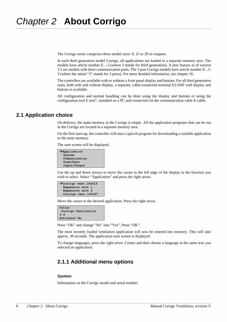
The start screen will be displayed.
Application System Communication Time/Date Input/Output
Use the up and down arrows to move the cursor in the left edge of the display to the function you wish to select. Select “Application” and press the right arrow.
Corrigo vent.140616 Expansion unit 1 Expansion unit 2 Corrigo vent.140327
Move the cursor to the desired application. Press the right arrow. Title: Corrigo Ventilation 3.4 Activate? No
Press ”OK” and change ”No” into ”Yes”. Press ”OK”.
The most recently loaded ventilation application will now be entered into memory. This will take approx. 30 seconds. The application start screen is displayed.
To change languages, press the right arrow 3 times and then choose a language in the same way you selected an application.
2.1.1 Additional menu options
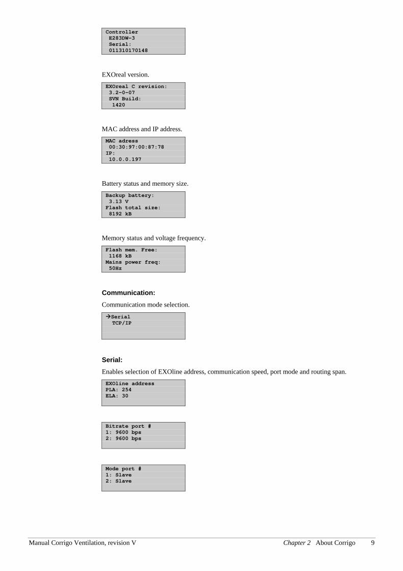
System: Information on the Corrigo model and serial number.
Manual Corrigo Ventilation, revision V Chapter 2 About Corrigo 9
Controller E283DW-3 Serial: 011310170148
EXOreal version. EXOreal C revision: 3.2-0-07 SVN Build: 1420
MAC address and IP address. MAC adress 00:30:97:00:87:78 IP: 10.0.0.197
Battery status and memory size. Backup battery: 3.13 V Flash total size: 8192 kB
Memory status and voltage frequency. Flash mem. Free: 1168 kB Mains power freq: 50Hz
Communication: Communication mode selection.
Serial TCP/IP
Serial: Enables selection of EXOline address, communication speed, port mode and routing span. EXOline address PLA: 254 ELA: 30
Bitrate port # 1: 9600 bps 2: 9600 bps
Mode port # 1: Slave 2: Slave
10 Chapter 2 About Corrigo Manual Corrigo Ventilation, revision V
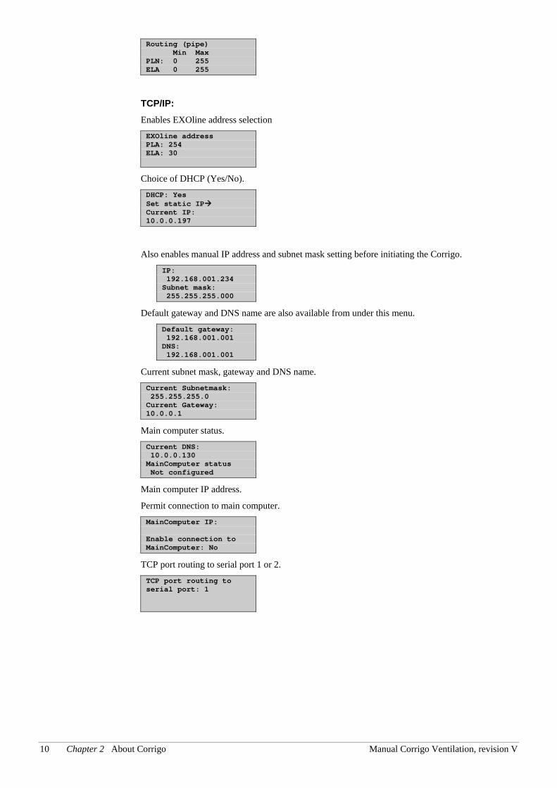
Routing (pipe) Min Max PLN: 0 255 ELA 0 255
TCP/IP: Enables EXOline address selection EXOline address PLA: 254 ELA: 30
Choice of DHCP (Yes/No). DHCP: Yes Set static IP Current IP: 10.0.0.197
Also enables manual IP address and subnet mask setting before initiating the Corrigo. IP: 192.168.001.234 Subnet mask: 255.255.255.000
Default gateway and DNS name are also available from under this menu. Default gateway: 192.168.001.001 DNS: 192.168.001.001
Current subnet mask, gateway and DNS name. Current Subnetmask: 255.255.255.0 Current Gateway: 10.0.0.1
Main computer status. Current DNS: 10.0.0.130 MainComputer status Not configured
Main computer IP address.
Permit connection to main computer. MainComputer IP: Enable connection to MainComputer: No
TCP port routing to serial port 1 or 2. TCP port routing to serial port: 1
Manual Corrigo Ventilation, revision V Chapter 2 About Corrigo 11
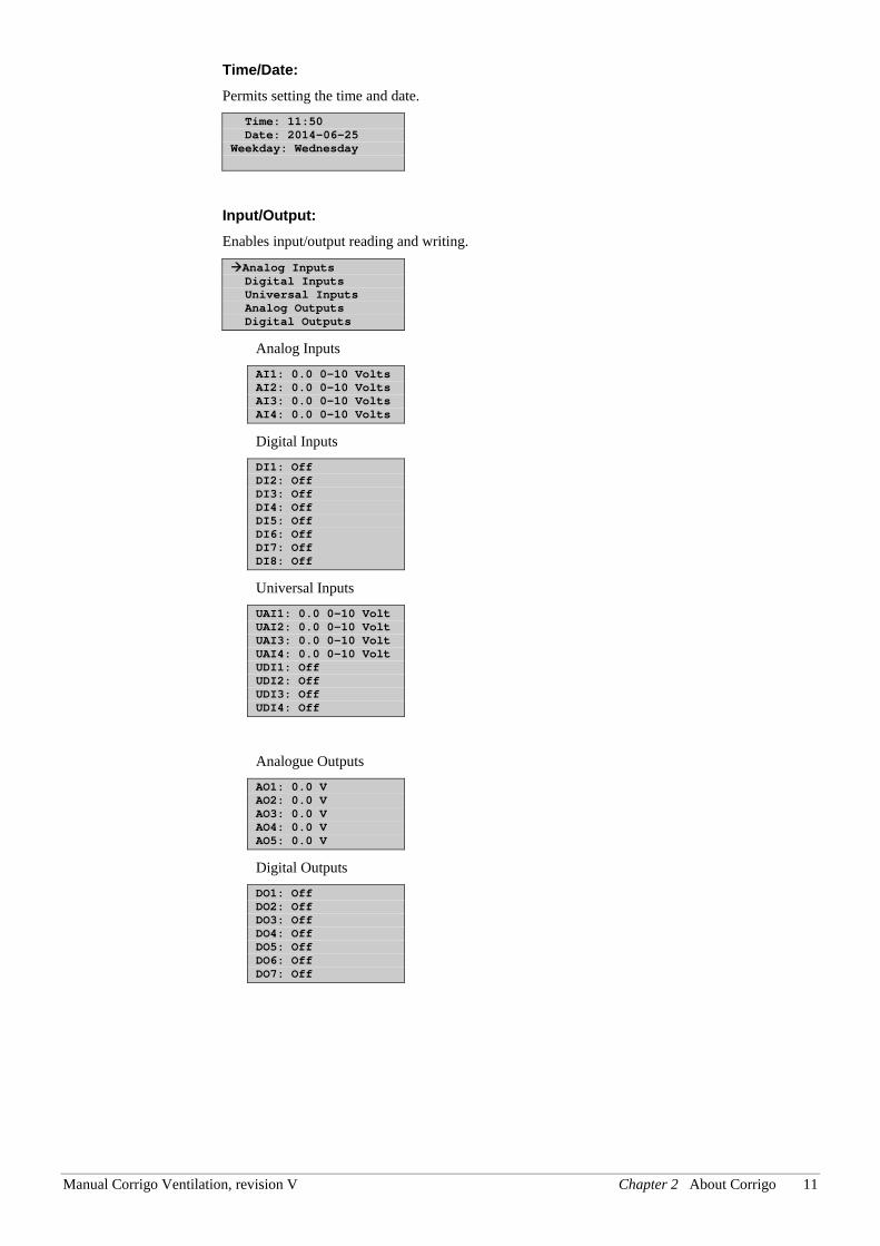
Time/Date: Permits setting the time and date. Time: 11:50 Date: 2014-06-25 Weekday: Wednesday
Input/Output: Enables input/output reading and writing.
Analog Inputs Digital Inputs Universal Inputs Analog Outputs Digital Outputs
Analog Inputs AI1: 0.0 0-10 Volts AI2: 0.0 0-10 Volts AI3: 0.0 0-10 Volts AI4: 0.0 0-10 Volts
Digital Inputs DI1: Off DI2: Off DI3: Off DI4: Off DI5: Off DI6: Off DI7: Off DI8: Off
Universal Inputs UAI1: 0.0 0-10 Volt UAI2: 0.0 0-10 Volt UAI3: 0.0 0-10 Volt UAI4: 0.0 0-10 Volt UDI1: Off UDI2: Off UDI3: Off UDI4: Off
Analogue Outputs AO1: 0.0 V AO2: 0.0 V AO3: 0.0 V AO4: 0.0 V AO5: 0.0 V
Digital Outputs DO1: Off DO2: Off DO3: Off DO4: Off DO5: Off DO6: Off DO7: Off
12 Chapter 2 About Corrigo Manual Corrigo Ventilation, revision V
2.1.2 Ventilation application The temperature controller is based on a supply air PI-controller for heating control with a pre-programmed set of control modes. A number of different control functions as well as analogue and digital in- and output functions can be bound to this controller. Certain functions are necessary, while others can be considered optional. The choice of which functions are to be used is free, the only restriction is the physical number of inputs and outputs of the different models. The maximum number of I/Os is 3*28 (a 2- or 3-port Corrigo with two expansion units).
The Corrigo is designed for DIN-rail mounting.
The program for an air handling unit contains, apart from other things, the following functions:
Different temperature control modes:
• Supply air temperature control, with or without outdoor temperature compensation
• Room temperature control (cascade control).
• Extract air control (cascade control).
• Seasonal switching between supply air temperature control and room/extract air
temperature control.
• Outdoor compensated room/extract air control.
• Extra, separate temperature control circuit for after-heaters, etc. Can also be controlled as cascade control.
• Extra control sequences Y4 and Y5 (in addition to Y1, Y2 and Y3) for free integration into the controller output.
With control of:
• Heat exchanger (liquid connected, plate or rotating) or mixing dampers.
• Heating coil: Water with or without frost protection or electric with high temperature limit switch.
• Cooling: Water or DX cooling in up to 3 steps.
• Circulation pumps heating, cooling, exchanger.
Fan control
• 1- or 2-speed supply air and extract air fans.
• Frequency controlled supply and extract air fans with pressure or flow control, manual control or external control from a VAV system.
• Pressure controlled supply air fan with slave connected extract air fan (output dependent or flow dependent) or opposite function (pressure controlled extract air fan with slave connected supply air fan, output dependent or flow dependent).
Humidity control It is possible to use either humidification or dehumidification, or to use combined humidification and dehumidification.
Timer control For starting and stopping the unit, annual clock function. Up to 5 timer outputs for control of external functions such as lighting, door locks etc.
Manual Corrigo Ventilation, revision V Chapter 2 About Corrigo 13
Demand controlled ventilation In buildings with strongly varying occupancy the fan speeds or mixing dampers can be controlled by the air quality measured by a CO2 sensor.
Support control When using the control function room control or extract air temperature control, it is possible to utilise support-heating and/or support-cooling.
Free cooling When this function has been activated, it is used during the summer to cool the building during the night using cool outdoor air thereby reducing the need to run chillers during the day.
Free heating
If the outdoor temperature is higher than the indoor temperature and there is a heating demand, the recovery damper will not open for recovery but instead open fully for outdoor air. This may occur during low night-time outdoor temperatures, when the room has been cooled considerably and the outside heat is rising faster than indoors. This function is activated at the same time as “Free cooling”.
Enthalpy control Measures and compares the energy content (enthalpy) of the outdoor air and the extract air (temperature and air humidity). When this function is active, the mixing damper signal will be overridden to recirculation if the enthalpy is higher outdoors than indoors.
Pretreatment Damper and pump control for preheating or precooling of the outdoor air via an underground intake channel.
Cooling recovery If the extract air is colder than the outdoor air and cooling is required, the heat exchanger control is reversed in order to return the cool extract air.
Recirculation control Recirculation of air using a supply air fan and (optionally) extract air fan and a recirculation damper with or without temperature control. Used as a recovery function or during heating with support control during the night. Recirculation control is available as an analogue or a digital function.
Step controllers Heating/Cooling As an alternative to the analogue control of ”Actuator heating Y1” or ”Actuator cooling Y3” step controllers can be used for controlling heating or cooling in steps using digital control.
Change-over In 2-pipe systems where a combination heater/cooler is operating together with a heat pump, Change-over is a function that enables using the same pipe for both heating and cooling, depending on which is currently required. It uses the output Y1 heating/Y3 cooling.
14 Chapter 2 About Corrigo Manual Corrigo Ventilation, revision V
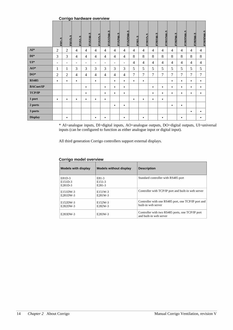
Corrigo hardware overview
E81
-3
E81
D-3
E15
1-3
E15
1W-3
E15
1D-3
E15
1DW
-3
E15
2W-3
E15
2DW
-3
E28
1-3
E28
1D-3
E28
1W-3
E28
1DW
-3
E28
2W-3
E28
2DW
-3
E28
3W-3
E28
3DW
-3
AI* 2 2 4 4 4 4 4 4 4 4 4 4 4 4 4 4 DI* 3 3 4 4 4 4 4 4 8 8 8 8 8 8 8 8 UI* - - - - - - - - 4 4 4 4 4 4 4 4 AO* 1 1 3 3 3 3 3 3 5 5 5 5 5 5 5 5 DO* 2 2 4 4 4 4 4 4 7 7 7 7 7 7 7 7 RS485 • • • • • • • • • • • • BACnet/IP • • • • • • • • • • TCP/IP • • • • • • • • • • 1 port • • • • • • • • • • 2 ports • • • • 3 ports • • Display • • • • • • • •
* AI=analogue inputs, DI=digital inputs, AO=analogue outputs, DO=digital outputs, UI=universal inputs (can be configured to function as either analogue input or digital input).
All third generation Corrigo controllers support external displays.
Corrigo model overview
Models with display Models without display Description
E81D-3 E151D-3 E281D-3
E81-3 E151-3 E281-3
Standard controller with RS485 port
E151DW-3 E281DW-3
E151W-3 E281W-3
Controller with TCP/IP port and built-in web server
E152DW-3 E282DW-3
E152W-3 E282W-3
Controller with one RS485 port, one TCP/IP port and built-in web server
E283DW-3 E283W-3 Controller with two RS485 ports, one TCP/IP port and built-in web server
Manual Corrigo Ventilation, revision V Chapter 2 About Corrigo 15
2.2 Technical data Protection class .................................................................................................................. IP20 Display ........................................................ 4 rows of 20 characters. Background illumination. LEDs Yellow ....................................................................................................... Settable parameter Red................................................................................................................ Alarm indication Clock .................................................................. Year base 24 hour clock with battery backup. Automatic summer-/winter-time changeover. Operating system .......................................................................................................... EXOreal Supply voltage .................................................... 24 V AC ±15%, 50…60 Hz or 21…36 V DC Power consumption ........................................ 5 VA, 3 W (DC), model …W: 9 VA, 5 W (DC) Dimensions .................................................................... 148x123x60 (WxHxD incl. terminals) Casing .......................................................................... Standard Euronorm (8.5 modules wide) Mounting ................................................................................................................ On DIN-rail Operation Climatic conditions according to IEC 721-3-3 ........................................................ Class 3k5 Ambient temperature ................................................................................................. 0...50°C Ambient humidity .............................................................................................. Max 95% RH Mechanical requirements according to IEC721-3-3 .............................................. Class 3M3 Vibration .......................................................... IEC60068-2-6, Test FC, vibration Sinusoidal Shock ................................................................................................ IEC60068-2-27, Test Ea Transport Climatic conditions according to IEC 721-3-2 ........................................................ Class 2k3 Ambient temperature .............................................................................................. -20...70°C Ambient humidity .............................................................................................. Max 95% RH Mechanical requirements according to IEC721-3-2 .............................................. Class 2M2 Vibration .......................................................... IEC60068-2-6, Test FC, vibration Sinusoidal Shock ................................................................................................ IEC60068-2-27, Test Ea Free fall .............................................................................................IEC60068-2-27, Test Ed Storage Climatic conditions according to IEC 721-3-1 ........................................................ Class 1k3 Ambient temperature .............................................................................................. -20...70°C Ambient humidity .............................................................................................. Max 95% RH Battery Type .....................................................................................Replaceable Lithium cell, CR2032 Battery life ................................................................................................... Better than 5 years Warning .................................................................................................... Low battery warning Battery backup ............................................................................... Memory and real time clock
Communication EXOline Port 1, insulated via a built-in RS485 contact. EXOline Port 2, via a built-in RS485 contact. EXOline TCP/IP. Modbus communication via serial RS485 communication or TCP/IP. Baudrate: 150, 300, 600, 1200, 2400, 4800, 9600 BACnet-AAC/IP via TCP/IP or BACnet-AAC MS/TP via RS485 Baudrate: 9600, 19200, 38400, 76800 Suitable model should be selected for appropriate needs. EMC emission and immunity standard This product conforms to the requirements of the EMC Directive 2004/108/EC through product standards EN 61000-6-1 and EN 61000-6-3.
RoHS
This product conforms to the Directive 2011/65/EU of the European Parliament and of the Council.
16 Chapter 2 About Corrigo Manual Corrigo Ventilation, revision V
Inputs Analogue inputs AI .............................................. Settable 0…10 V DC or PT1000, 12 bit A/D Digital inputs DI ....................................................................................... Potential-free closure Universal inputs UI ........................................... Can be set to act as either an analogue input or a digital input with specifications as above Outputs Analogue outputs AO ............................................... Configurable 0…10 V DC; 2…10 V DC; 10…0 V DC or 10…2 V DC 8 bit D/A short-circuit protected Digital outputs DO ........................................... Mosfet outputs, 24 V AC/DC, 2 A continuous.
Totally max 8 A. 24V DC output(+C) Voltage.................................................................................................... ........... 24 V DC+- 2V Max charge ....................................................................................................................... 0.1 A Options …W (TCP/IP-port) ........................................................ EXOline and Modbus communication 2-port Corrigo models ........................ Two serial ports or one serial port and one TCP/IP port 3 ports Corrigo............................................................ .... Two serial ports and one TCP/IP port External hand terminal, E3-DSP ............................. For use with Corrigo units without display External room unit...................................................................... ED-RU / ED-RUD / ED-TCV
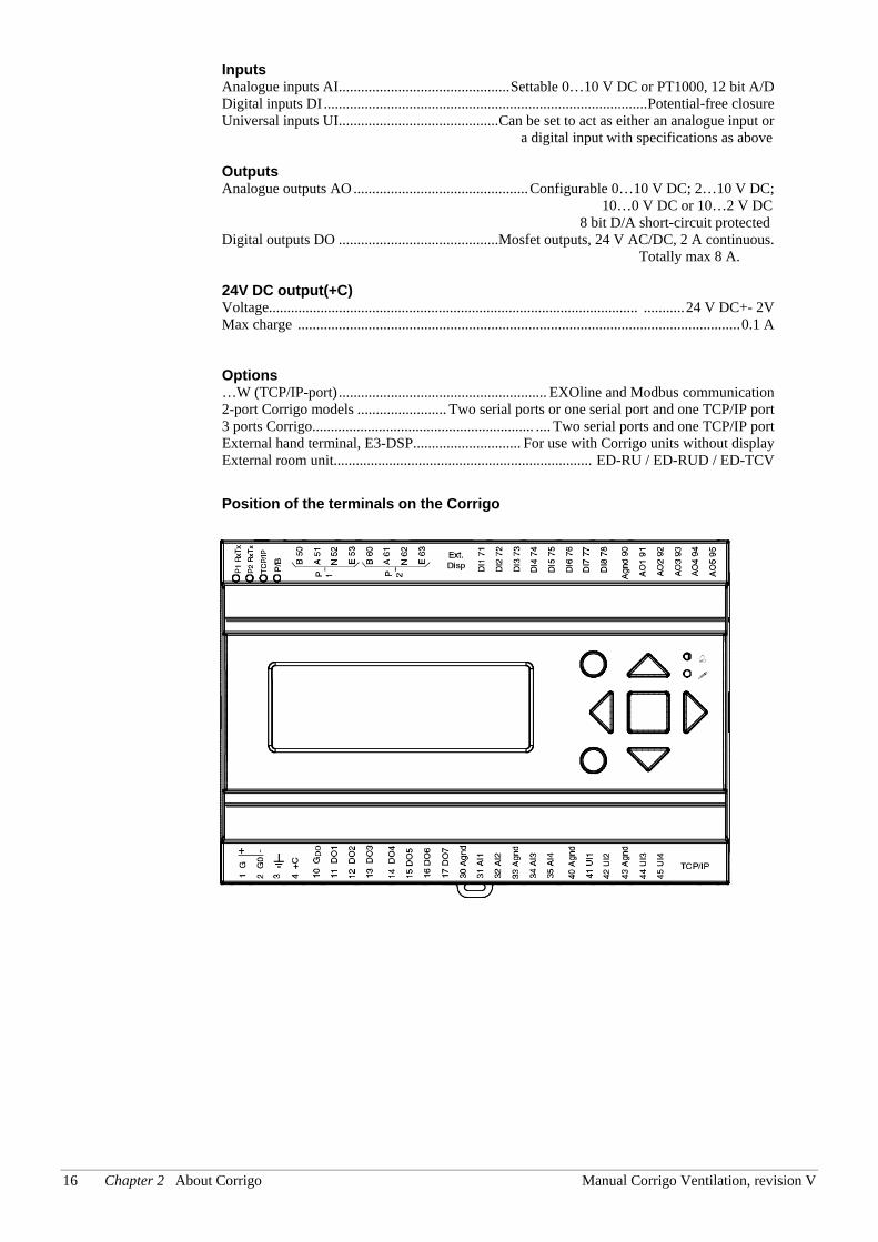
Position of the terminals on the Corrigo
Manual Corrigo Ventilation, revision V Chapter 3 Installation and wiring 17
Chapter 3 Installation and wiring
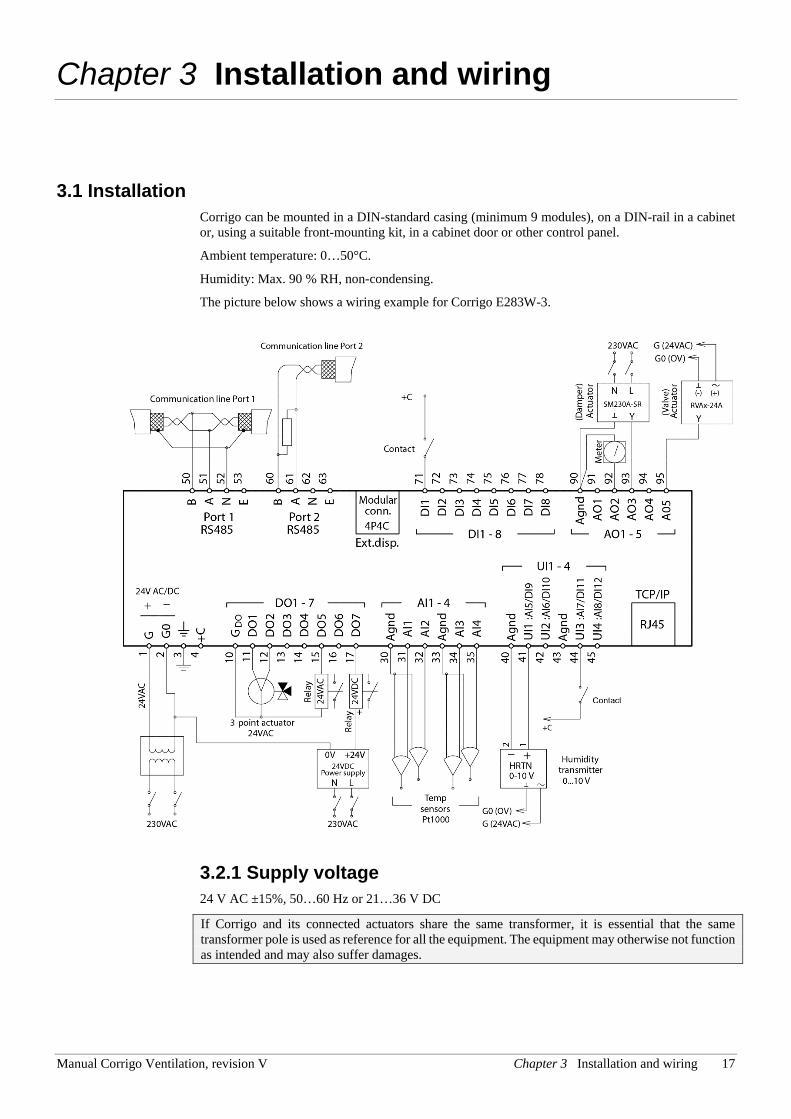
3.1 Installation Corrigo can be mounted in a DIN-standard casing (minimum 9 modules), on a DIN-rail in a cabinet or, using a suitable front-mounting kit, in a cabinet door or other control panel.
Ambient temperature: 0…50°C.
Humidity: Max. 90 % RH, non-condensing.
The picture below shows a wiring example for Corrigo E283W-3.
3.2.1 Supply voltage 24 V AC ±15%, 50…60 Hz or 21…36 V DC
If Corrigo and its connected actuators share the same transformer, it is essential that the same transformer pole is used as reference for all the equipment. The equipment may otherwise not function as intended and may also suffer damages.
18 Chapter 3 Installation and wiring Manual Corrigo Ventilation, revision V
3.2.2 Inputs and outputs The list of input and output functions in section 3.2.3 is a handy instrument to help you keep track of which inputs and outputs you will need to configure.
Analogue inputs Analogue inputs must refer to an Agnd terminal placed in the same terminal block as the input being wired.
Analogue inputs can, depending on the configuration, be used for either PT1000 temperature sensors or for 0…10 V DC analogue input signals, for example from a pressure transmitter.
Digital inputs Digital inputs must refer to +C on terminal 4. Digital inputs may only be wired to voltage-free contacts. Any external voltage applied to a digital input may harm the unit. The input signal can be set to either NO or NC.
Universal inputs A universal input can be configured to act as either an analogue input or as a digital input.
A universal input configured as an analogue input can, depending on the configuration, be used for either PT1000 temperature sensors or for 0…10 V DC analogue input signals, for example from a pressure transmitter.
Universal inputs configured as an analogue input must refer to an Agnd terminal placed in the same terminal block as the input being wired.
A universal input configured as a digital input must, just like other digital inputs refer to C+ on terminal 4. It may only be wired to voltage-free contacts.
Analogue outputs Analogue outputs must refer to the Agnd terminal placed in the AO terminal block.
All analogue outputs can be individually set to any one of the following signals:
0…10 V DC
2…10 V DC
10…0 V DC
10…2 V DC
If the Corrigo and the actuators connected to it share the same transformer it is essential that the same transformer-pole is used as reference for all the equipment. Failure to do so will prevent the equipment from functioning as intended and may also lead to damages.
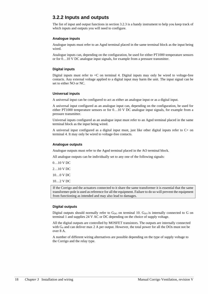
Digital outputs Digital outputs should normally refer to GDO on terminal 10. GDO is internally connected to G on terminal 1 and supplies 24 V AC or DC depending on the choice of supply voltage.
All the digital outputs are controlled by MOSFET transistors. The outputs are internally connected with G0 and can deliver max 2 A per output. However, the total power for all the DOs must not be over 8 A.
A number of different wiring alternatives are possible depending on the type of supply voltage to the Corrigo and the relay type.
Manual Corrigo Ventilation, revision V Chapter 3 Installation and wiring 19
24 V AC supply and 24 V AC relays
24 V DC supply and 24 V DC relays
24 V AC supply and 24 V DC relays
GG0
101112
LN
24 VAC
GG0
101112
+-
24 V DC
+ -
+ -
+ -
GG0
101112
LN
24 VAC
24 V
DC
+ -
+ -
+ -
+ -
24 V AC
24 V AC
20 Chapter 3 Installation and wiring Manual Corrigo Ventilation, revision V
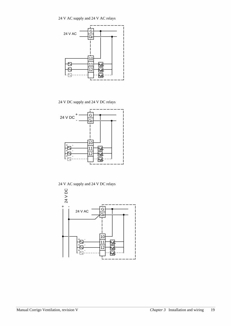
24 V DC supply and 24 V AC relays
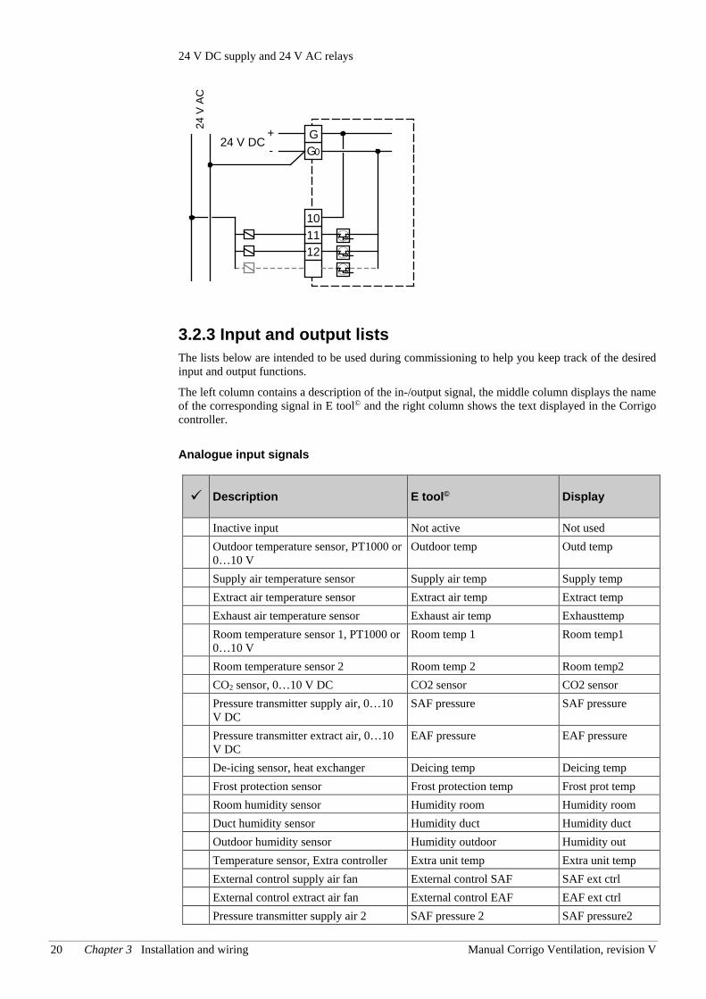
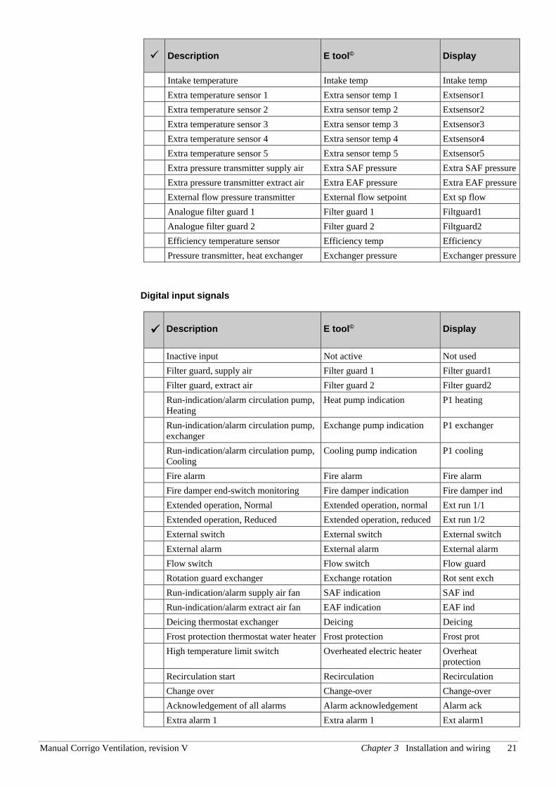
3.2.3 Input and output lists The lists below are intended to be used during commissioning to help you keep track of the desired input and output functions.
The left column contains a description of the in-/output signal, the middle column displays the name of the corresponding signal in E tool© and the right column shows the text displayed in the Corrigo controller.
Analogue input signals
Description E tool© Display
Inactive input Not active Not used Outdoor temperature sensor, PT1000 or
0…10 V Outdoor temp Outd temp
Supply air temperature sensor Supply air temp Supply temp Extract air temperature sensor Extract air temp Extract temp Exhaust air temperature sensor Exhaust air temp Exhausttemp Room temperature sensor 1, PT1000 or
0…10 V Room temp 1 Room temp1
Room temperature sensor 2 Room temp 2 Room temp2 CO2 sensor, 0…10 V DC CO2 sensor CO2 sensor Pressure transmitter supply air, 0…10
V DC SAF pressure SAF pressure
Pressure transmitter extract air, 0…10 V DC
EAF pressure EAF pressure
De-icing sensor, heat exchanger Deicing temp Deicing temp Frost protection sensor Frost protection temp Frost prot temp Room humidity sensor Humidity room Humidity room Duct humidity sensor Humidity duct Humidity duct Outdoor humidity sensor Humidity outdoor Humidity out Temperature sensor, Extra controller Extra unit temp Extra unit temp External control supply air fan External control SAF SAF ext ctrl External control extract air fan External control EAF EAF ext ctrl Pressure transmitter supply air 2 SAF pressure 2 SAF pressure2
GG0
101112
+-
24 V DC
24 V
AC
L N24 V
AC
Manual Corrigo Ventilation, revision V Chapter 3 Installation and wiring 21
Description E tool© Display
Intake temperature Intake temp Intake temp Extra temperature sensor 1 Extra sensor temp 1 Extsensor1 Extra temperature sensor 2 Extra sensor temp 2 Extsensor2 Extra temperature sensor 3 Extra sensor temp 3 Extsensor3 Extra temperature sensor 4 Extra sensor temp 4 Extsensor4 Extra temperature sensor 5 Extra sensor temp 5 Extsensor5 Extra pressure transmitter supply air Extra SAF pressure Extra SAF pressure Extra pressure transmitter extract air Extra EAF pressure Extra EAF pressure External flow pressure transmitter External flow setpoint Ext sp flow Analogue filter guard 1 Filter guard 1 Filtguard1 Analogue filter guard 2 Filter guard 2 Filtguard2 Efficiency temperature sensor Efficiency temp Efficiency Pressure transmitter, heat exchanger Exchanger pressure Exchanger pressure
Digital input signals
Description E tool© Display
Inactive input Not active Not used Filter guard, supply air Filter guard 1 Filter guard1 Filter guard, extract air Filter guard 2 Filter guard2 Run-indication/alarm circulation pump,
Heating Heat pump indication P1 heating
Run-indication/alarm circulation pump, exchanger
Exchange pump indication P1 exchanger
Run-indication/alarm circulation pump, Cooling
Cooling pump indication P1 cooling
Fire alarm Fire alarm Fire alarm Fire damper end-switch monitoring Fire damper indication Fire damper ind Extended operation, Normal Extended operation, normal Ext run 1/1 Extended operation, Reduced Extended operation, reduced Ext run 1/2 External switch External switch External switch External alarm External alarm External alarm Flow switch Flow switch Flow guard Rotation guard exchanger Exchange rotation Rot sent exch Run-indication/alarm supply air fan SAF indication SAF ind Run-indication/alarm extract air fan EAF indication EAF ind Deicing thermostat exchanger Deicing Deicing Frost protection thermostat water heater Frost protection Frost prot High temperature limit switch Overheated electric heater Overheat
protection Recirculation start Recirculation Recirculation Change over Change-over Change-over Acknowledgement of all alarms Alarm acknowledgement Alarm ack Extra alarm 1 Extra alarm 1 Ext alarm1
22 Chapter 3 Installation and wiring Manual Corrigo Ventilation, revision V
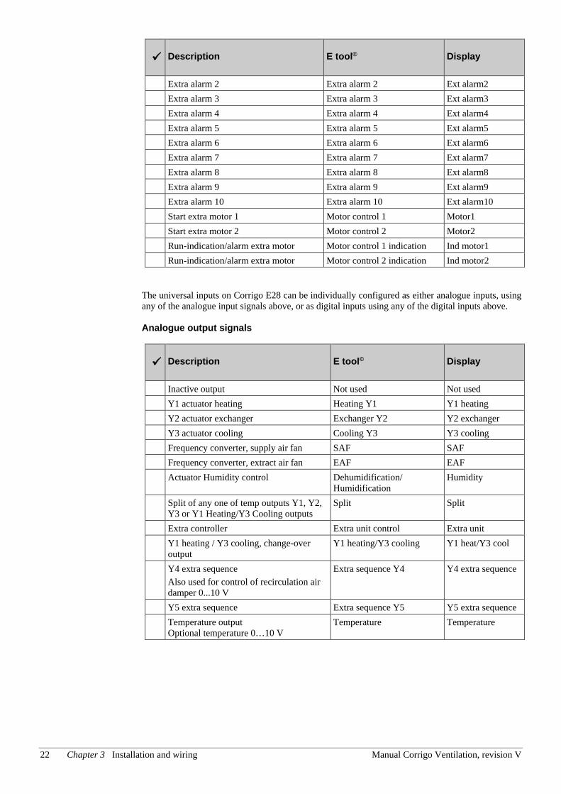
Description E tool© Display
Extra alarm 2 Extra alarm 2 Ext alarm2 Extra alarm 3 Extra alarm 3 Ext alarm3 Extra alarm 4 Extra alarm 4 Ext alarm4 Extra alarm 5 Extra alarm 5 Ext alarm5 Extra alarm 6 Extra alarm 6 Ext alarm6 Extra alarm 7 Extra alarm 7 Ext alarm7 Extra alarm 8 Extra alarm 8 Ext alarm8 Extra alarm 9 Extra alarm 9 Ext alarm9 Extra alarm 10 Extra alarm 10 Ext alarm10 Start extra motor 1 Motor control 1 Motor1 Start extra motor 2 Motor control 2 Motor2 Run-indication/alarm extra motor Motor control 1 indication Ind motor1 Run-indication/alarm extra motor Motor control 2 indication Ind motor2
The universal inputs on Corrigo E28 can be individually configured as either analogue inputs, using any of the analogue input signals above, or as digital inputs using any of the digital inputs above. Analogue output signals
Description E tool© Display
Inactive output Not used Not used Y1 actuator heating Heating Y1 Y1 heating Y2 actuator exchanger Exchanger Y2 Y2 exchanger Y3 actuator cooling Cooling Y3 Y3 cooling Frequency converter, supply air fan SAF SAF Frequency converter, extract air fan EAF EAF Actuator Humidity control Dehumidification/
Humidification Humidity
Split of any one of temp outputs Y1, Y2, Y3 or Y1 Heating/Y3 Cooling outputs
Split Split
Extra controller Extra unit control Extra unit Y1 heating / Y3 cooling, change-over
output Y1 heating/Y3 cooling Y1 heat/Y3 cool
Y4 extra sequence Also used for control of recirculation air damper 0...10 V
Extra sequence Y4 Y4 extra sequence
Y5 extra sequence Extra sequence Y5 Y5 extra sequence Temperature output
Optional temperature 0…10 V Temperature Temperature
Manual Corrigo Ventilation, revision V Chapter 3 Installation and wiring 23
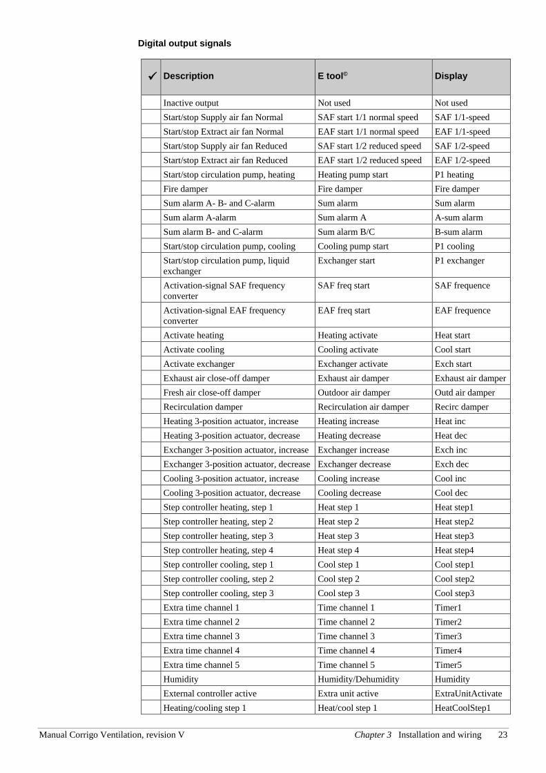
Digital output signals
Description E tool© Display
Inactive output Not used Not used Start/stop Supply air fan Normal SAF start 1/1 normal speed SAF 1/1-speed Start/stop Extract air fan Normal EAF start 1/1 normal speed EAF 1/1-speed Start/stop Supply air fan Reduced SAF start 1/2 reduced speed SAF 1/2-speed Start/stop Extract air fan Reduced EAF start 1/2 reduced speed EAF 1/2-speed Start/stop circulation pump, heating Heating pump start P1 heating Fire damper Fire damper Fire damper Sum alarm A- B- and C-alarm Sum alarm Sum alarm Sum alarm A-alarm Sum alarm A A-sum alarm Sum alarm B- and C-alarm Sum alarm B/C B-sum alarm Start/stop circulation pump, cooling Cooling pump start P1 cooling Start/stop circulation pump, liquid
exchanger Exchanger start P1 exchanger
Activation-signal SAF frequency converter
SAF freq start SAF frequence
Activation-signal EAF frequency converter
EAF freq start EAF frequence
Activate heating Heating activate Heat start Activate cooling Cooling activate Cool start Activate exchanger Exchanger activate Exch start Exhaust air close-off damper Exhaust air damper Exhaust air damper Fresh air close-off damper Outdoor air damper Outd air damper Recirculation damper Recirculation air damper Recirc damper Heating 3-position actuator, increase Heating increase Heat inc Heating 3-position actuator, decrease Heating decrease Heat dec Exchanger 3-position actuator, increase Exchanger increase Exch inc Exchanger 3-position actuator, decrease Exchanger decrease Exch dec Cooling 3-position actuator, increase Cooling increase Cool inc Cooling 3-position actuator, decrease Cooling decrease Cool dec Step controller heating, step 1 Heat step 1 Heat step1 Step controller heating, step 2 Heat step 2 Heat step2 Step controller heating, step 3 Heat step 3 Heat step3 Step controller heating, step 4 Heat step 4 Heat step4 Step controller cooling, step 1 Cool step 1 Cool step1 Step controller cooling, step 2 Cool step 2 Cool step2 Step controller cooling, step 3 Cool step 3 Cool step3 Extra time channel 1 Time channel 1 Timer1 Extra time channel 2 Time channel 2 Timer2 Extra time channel 3 Time channel 3 Timer3 Extra time channel 4 Time channel 4 Timer4 Extra time channel 5 Time channel 5 Timer5 Humidity Humidity/Dehumidity Humidity External controller active Extra unit active ExtraUnitActivate Heating/cooling step 1 Heat/cool step 1 HeatCoolStep1
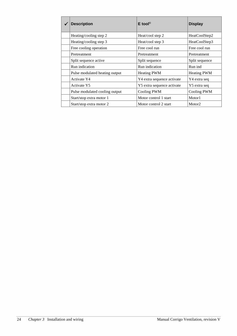
24 Chapter 3 Installation and wiring Manual Corrigo Ventilation, revision V
Description E tool© Display
Heating/cooling step 2 Heat/cool step 2 HeatCoolStep2 Heating/cooling step 3 Heat/cool step 3 HeatCoolStep3 Free cooling operation Free cool run Free cool run Pretreatment Pretreatment Pretreatment Split sequence active Split sequence Split sequence Run indication Run indication Run ind Pulse modulated heating output Heating PWM Heating PWM Activate Y4 Y4 extra sequence activate Y4 extra seq Activate Y5 Y5 extra sequence activate Y5 extra seq Pulse modulated cooling output Cooling PWM Cooling PWM Start/stop extra motor 1 Motor control 1 start Motor1 Start/stop extra motor 2 Motor control 2 start Motor2
Manual Corrigo Ventilation, revision V Chapter 4 Commissioning 25
Chapter 4 Commissioning
General Before the Corrigo can be used, all inputs and outputs must first be configured, as well as all relevant parameters.
All commissioning can be done using the Corrigo front panel display and buttons or using the external display unit E3-DSP.
E tool© The best way however, is to configure the Corrigo by using E tool©.
E tool© is a PC-based configuration program specially developed to simplify the commissioning of the Corrigo series.
When using E tool© the whole configuration and all settings can be done on the computer and then be downloaded to the Corrigo. An infinite number of different configurations can be saved in computer memory for later use.
A communication cable is required in order to configure Corrigo. E-CABLE2-USB or E-CABLE-RS232 are used for controllers featuring RS485 communication, and an E-CABLE-TCP/IP (crossover network cable) for controllers with a TCP/IP port.
The Corrigo must be powered up and the application selected in order for it to be configured.
4.1 How to do it For configuration using E tool©, see the E tool© manual.
For configuration using the front panel or E3-DSP, there are two ways to go depending on how much help you need.
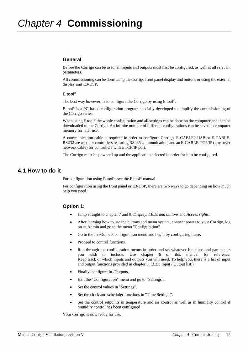
Option 1: • Jump straight to chapter 7 and 8, Display, LEDs and buttons and Access rights.
• After learning how to use the buttons and menu system, connect power to your Corrigo, log on as Admin and go to the menu "Configuration".
• Go to the In-/Outputs configuration menu and begin by configuring these.
• Proceed to control functions.
• Run through the configuration menus in order and set whatever functions and parameters you wish to include. Use chapter 6 of this manual for reference. Keep track of which inputs and outputs you will need. To help you, there is a list of input and output functions provided in chapter 3, (3.2.3 Input / Output list.)
• Finally, configure In-/Outputs.
• Exit the "Configuration" menu and go to "Settings".
• Set the control values in "Settings".
• Set the clock and scheduler functions in "Time Settings".
• Set the control setpoints in temperature and air control as well as in humidity control if humidity control has been configured
Your Corrigo is now ready for use.
26 Chapter 4 Commissioning Manual Corrigo Ventilation, revision V
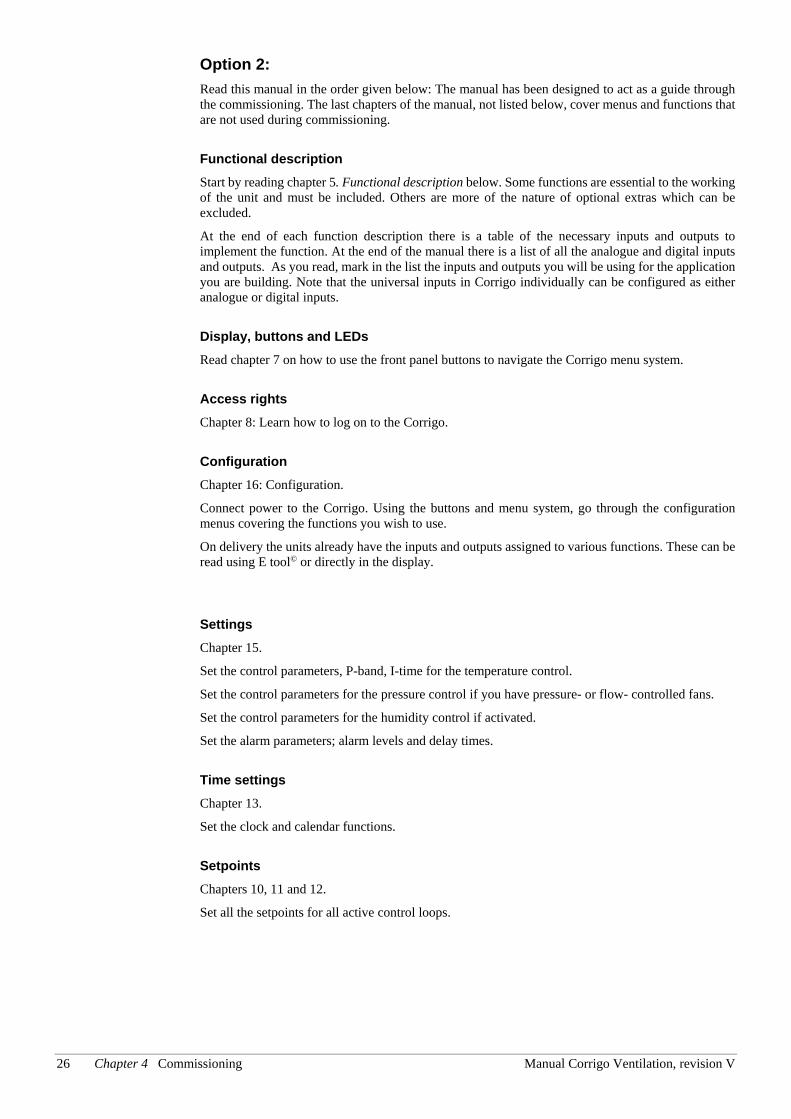
Option 2: Read this manual in the order given below: The manual has been designed to act as a guide through the commissioning. The last chapters of the manual, not listed below, cover menus and functions that are not used during commissioning.
Functional description Start by reading chapter 5. Functional description below. Some functions are essential to the working of the unit and must be included. Others are more of the nature of optional extras which can be excluded.
At the end of each function description there is a table of the necessary inputs and outputs to implement the function. At the end of the manual there is a list of all the analogue and digital inputs and outputs. As you read, mark in the list the inputs and outputs you will be using for the application you are building. Note that the universal inputs in Corrigo individually can be configured as either analogue or digital inputs.
Display, buttons and LEDs Read chapter 7 on how to use the front panel buttons to navigate the Corrigo menu system.
Access rights Chapter 8: Learn how to log on to the Corrigo.
Configuration Chapter 16: Configuration.
Connect power to the Corrigo. Using the buttons and menu system, go through the configuration menus covering the functions you wish to use.
On delivery the units already have the inputs and outputs assigned to various functions. These can be read using E tool© or directly in the display.
Settings Chapter 15.
Set the control parameters, P-band, I-time for the temperature control.
Set the control parameters for the pressure control if you have pressure- or flow- controlled fans.
Set the control parameters for the humidity control if activated.
Set the alarm parameters; alarm levels and delay times.
Time settings Chapter 13.
Set the clock and calendar functions.
Setpoints Chapters 10, 11 and 12.
Set all the setpoints for all active control loops.
Manual Corrigo Ventilation, revision V Chapter 4 Commissioning 27
Manual/Auto Chapter 14.
Learn to use manual control. A very useful tool for testing out and troubleshooting your system.
Other functions Chapter 18.
Alarm handling etc.
28 Chapter 5 Functional description Manual Corrigo Ventilation, revision V
Chapter 5 Functional description
5.1 Temperature control
General Corrigo has a choice of the following control modes:
1. Supply air control
2. Outdoor temperature compensated supply air control
3. Cascaded room temperature control
4. Cascade connected extract air temperature control
5. Outdoor temperature dependent switching between supply air control with outdoor temperature compensation and room temperature control
6. Outdoor temperature dependent switching between supply air control with outdoor temperature compensation and extract air control
7. Outdoor compensated room temperature control
8. Outdoor compensated extract air control
The supply air temperature controller is reverse acting, i e. the output will increase for decreasing temperature. The controller is a PI-controller with settable P-band and I-time.
In the first mode, the temperature at the supply air sensor will be constantly kept at the user setpoint value. In the second mode, the supply air temperature setpoint is adjusted depending on the outdoor temperature.
In modes three and four the supply air is controlled as part of a cascade controller together with the room/extract temperature controller. The room/extract temperature offset will dictate the supply air temperature setpoint.
Mode five and six vary according to the outdoor temperature: Outdoor temperature compensated supply air control, as in mode two, in winter and cascaded room control or cascaded extract air control in summer, as in modes three or four. The switch-over temperature is settable.
In applications with mixing dampers instead of heat exchanger the signal for the damper control will be reversed compared to the signal for heat exchanger control i. e. decreasing signal on increasing heat demand. This is done automatically on configuring the exchanger output = dampers.
The heater can be either a hot water heater battery or an electric heater.
Outputs The supply air controller output is split between one or more of the output blocks "Heating Y1", "Exchanger Y2" and "Cooling Y3". Each of these output blocks can be bound to either an analogue 0…10 V DC output or to two digital 3-position increase/decrease outputs.
Each output block has two parameters for setting the control range:
Heating Controller Output signal (HCOut) at which the output should be 0 %
Heating Controller Output signal (HCOut) at which the output should be 100 %
These settings are used to establish the output activation order and to split the P-band between the outputs.
Manual Corrigo Ventilation, revision V Chapter 5 Functional description 29
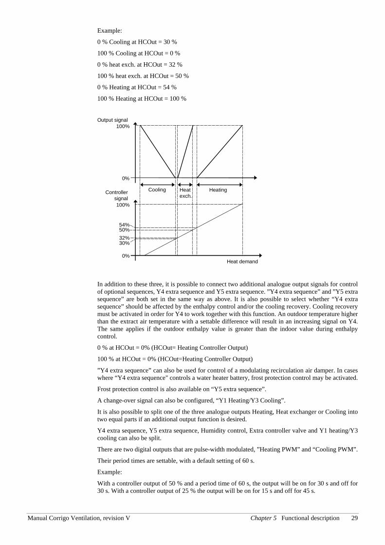
Example:
0 % Cooling at HCOut = 30 %
100 % Cooling at HCOut = 0 %
0 % heat exch. at HCOut = 32 %
100 % heat exch. at HCOut = 50 %
0 % Heating at HCOut = 54 %
100 % Heating at HCOut = 100 %
In addition to these three, it is possible to connect two additional analogue output signals for control of optional sequences, Y4 extra sequence and Y5 extra sequence. ”Y4 extra sequence” and ”Y5 extra sequence” are both set in the same way as above. It is also possible to select whether “Y4 extra sequence” should be affected by the enthalpy control and/or the cooling recovery. Cooling recovery must be activated in order for Y4 to work together with this function. An outdoor temperature higher than the extract air temperature with a settable difference will result in an increasing signal on Y4. The same applies if the outdoor enthalpy value is greater than the indoor value during enthalpy control.
0 % at HCOut = 0% (HCOut= Heating Controller Output)
100 % at HCOut = 0% (HCOut=Heating Controller Output)
”Y4 extra sequence” can also be used for control of a modulating recirculation air damper. In cases where “Y4 extra sequence" controls a water heater battery, frost protection control may be activated.
Frost protection control is also available on “Y5 extra sequence”.
A change-over signal can also be configured, “Y1 Heating/Y3 Cooling”.
It is also possible to split one of the three analogue outputs Heating, Heat exchanger or Cooling into two equal parts if an additional output function is desired.
Y4 extra sequence, Y5 extra sequence, Humidity control, Extra controller valve and Y1 heating/Y3 cooling can also be split.
There are two digital outputs that are pulse-width modulated, ”Heating PWM” and “Cooling PWM”.
Their period times are settable, with a default setting of 60 s.
Example:
With a controller output of 50 % and a period time of 60 s, the output will be on for 30 s and off for 30 s. With a controller output of 25 % the output will be on for 15 s and off for 45 s.
54%50%32%30%
0%
0%
Controllersignal
Cooling HeatingHeatexch.
Output signal100%
100%
Heat demand
30 Chapter 5 Functional description Manual Corrigo Ventilation, revision V
5.1.1 Control modes
1. Supply air control The supply air temperature is kept at the setpoint value by controlling the output signals for "Heating Y1", "Exchanger Y2", "Cooling Y3", "Extra sequence Y4" and “Extra sequence Y5”. A single PI control loop is used.
A neutral zone can be set around the setpoint value.
Example: If the setpoint is 18 °C and the neutral zone is 2 K, the cooling setpoint will be 19 °C and the heating setpoint will be 17 °C (FS=0 K). If the supply air temperature is in the neutral zone, the heating and cooling will be blocked. If the supply air temperature decreases below the setpoint –NZ/2 the heating signal will be active until setpoint is fulfilled. If the supply air temperature increases above the setpoint +NZ/2 the cooling signal will be active until setpoint is fulfilled.
The setpoint value is set using the front panel or alternatively using an external setpoint device.
Alarms which are activated when the supply air temperature is too high or too low are active.
Alarm for control offset of the supply air temperature is active.
2. Outdoor temperature compensated supply air control The supply air temperature setpoint is outdoor temperature compensated using a control curve with 8 node points.
The supply air temperature is kept at the setpoint value by controlling the output signals for "Y1 heating", "Y2 exchanger", "Y3 cooling", "Extra sequence Y4" and “Extra sequence Y5”. A single PI control loop is used.
Alarms which are activated when the supply air temperature is too high or too low are active.
Alarm for control offset of the supply air temperature is active.
3. Cascaded room temperature control Cascade control of room temperature and supply air temperature to achieve a constant, settable room temperature. The room controller output signal generates the supply air controller’s setpoint value.
One or two room sensors can be connected. If two sensors are connected the average of their values will be used. The number of room sensors is detected automatically. The room temperature is kept at the setpoint value by controlling the output signals for "Y1 heating", "Y2 exchanger", "Y3 cooling", "Extra sequence Y4" and “Extra sequence Y5”. Two PI loops are used.
The room setpoint value is set using the front panel or alternatively using an external setpoint device.
4. Cascaded extract air temperature control Cascade control of extract air temperature and supply air temperature to achieve a constant, settable room temperature. The extract air controller output signal generates the supply air controller’s setpoint value.
The extract air temperature is kept at the setpoint value by controlling the output signals for "Y1 heating", "Y2 exchanger", "Y3 Cooling", "Extra sequence Y4" and “Extra sequence Y5”. Two PI loops are used.
The extract air setpoint value is set using the front panel or, alternatively, by using an external setpoint device.
5. Outdoor temperature dependent switching between supply air temperature control and room temperature control When the outdoor temperature is lower than a settable limit (winter), outdoor compensated supply air temperature control will be active, otherwise (summer) cascaded room temperature control.
Manual Corrigo Ventilation, revision V Chapter 5 Functional description 31
6. Outdoor temperature dependent switching between supply air temperature control and extract air temperature control When the outdoor temperature is lower than a settable limit (winter), outdoor compensated supply air temperature control will be active, otherwise (summer) cascaded room temperature control as in control mode 4.
7. Outdoor compensated room temperature control The room temperature can be compensated when the outdoor temperature increases. One can, for instance, imagine accepting a slightly higher room temperature if it is warm outside or, conversely, a slightly lower temperature if it is chilly. This function is included to conserve energy.
8. Outdoor compensated extract air control The extract air temperature can be compensated when the outdoor temperature increases. One can, for instance, imagine accepting a slightly higher extract air temperature if it is warm outside or, conversely, a slightly lower extract air temperature if it is chilly. This function is included to conserve energy.
In- and outputs
1 2 3 4 5 6 7 8 Control mode
AI AI AI AI AI AI AI AI Supply air sensor AI AI AI AI AI Outdoor temperature sensor AI AI AI Room sensor AI AI AI Extract air sensor
AO AO AO AO AO AO AO AO Y1 heating 0…10 V DC ** AO AO AO AO AO AO AO AO Y2 exchanger 0…10 V DC ** AO AO AO AO AO AO AO AO Y3 cooling 0…10 V DC ** AO AO AO AO AO AO AO AO Y4 extra sequence 0...10 V DC AO AO AO AO AO AO AO AO Extra split Y1, Y2 or Y3 0…10 V DC (optional) AO AO AO AO AO AO AO AO Y1 heating/Y3 cooling
Change-over (option) DO DO DO DO DO DO DO DO Heating 3-pos. increase ** DO DO DO DO DO DO DO DO Heating 3-pos. decrease ** DO DO DO DO DO DO DO DO Exch. 3-pos. increase ** DO DO DO DO DO DO DO DO Exch. 3-pos. decrease ** DO DO DO DO DO DO DO DO Cooling 3-pos. increase ** DO DO DO DO DO DO DO DO Cooling 3-pos. decrease **
** Choose output type depending on the actuator type: Either AO 0…10 V or DO 3-position increase/decrease.
5.1.2 Heater types
5.1.2.1 Water heating
Control When the unit is in running mode the heating valve is controlled by the analogue output ”Y1 heating” or by two digital outputs “Heating 3-pos. actuator, increase” and “Heating, 3-pos. actuator, decrease”.
32 Chapter 5 Functional description Manual Corrigo Ventilation, revision V
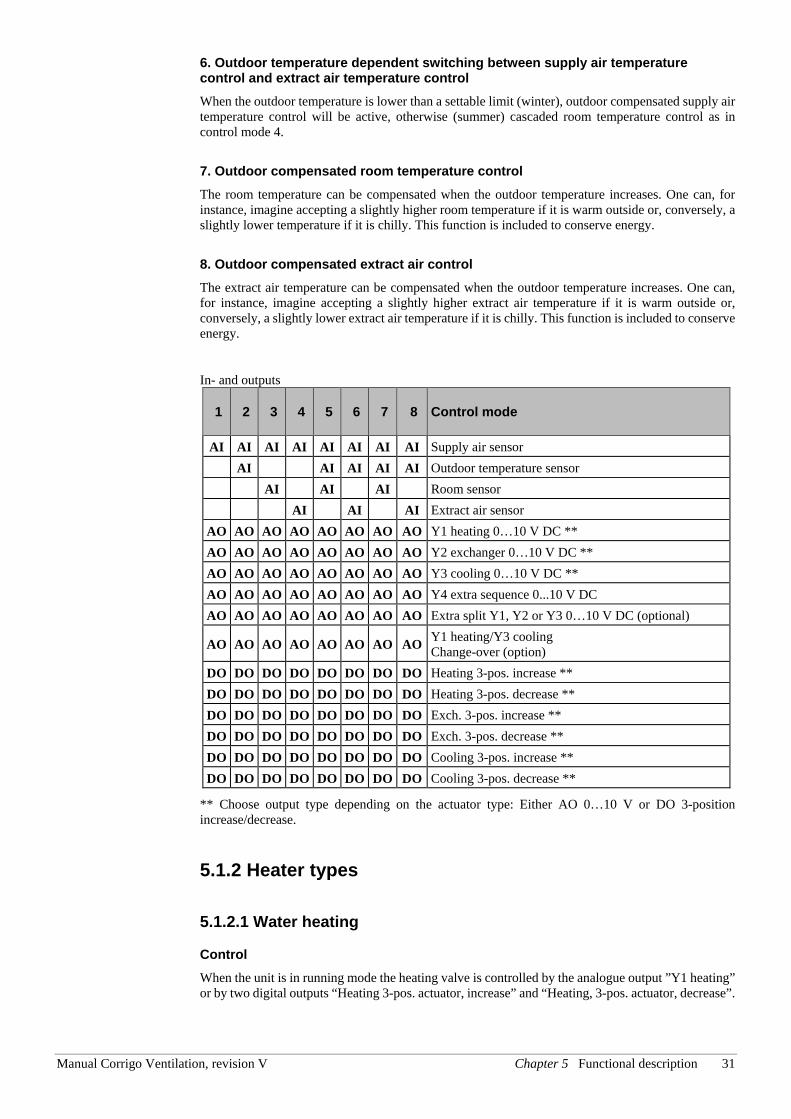
Frost protection The heater return water temperature is measured using the analogue input ”Frost prot.temp”. Low temperatures will generate an internal, proportional signal that is used to force the heating valve open thereby preventing freeze-up of the heater.
The internal signal (“Internal signal”) will begin to rise as the frost protection temperature falls below “Alarm level” + “Prop. Band” in order to reach 100 % output when the signal has fallen to “Alarm level”.
When ”Internal signal” reaches 100 % or the digital input ”Deicing heat exchanger” is activated, the unit is shut down, the heating output is set to completely open mode and an alarm is activated. The unit is restarted when the alarm has been acknowledged and the temperature for the frost protection sensor has risen above “Alarm limit frost” + “P-Band”.
Frost protection control is available on Y1 heating, Y4 extra sequence or on both Y1 and Y4. Frost protection control is also available on “Y5 extra sequence”.
The frost protection alarm level is set in the menu Settings/Alarm settings/Alarm limit.
Shutdown mode If frost protection is activated the controller will go into ”Shutdown mode” when the running mode switches to ”Off”. The shutdown controller will control the heating output to maintain a constant settable temperature at the frost protection sensor.
5.1.2.2 Electric heating
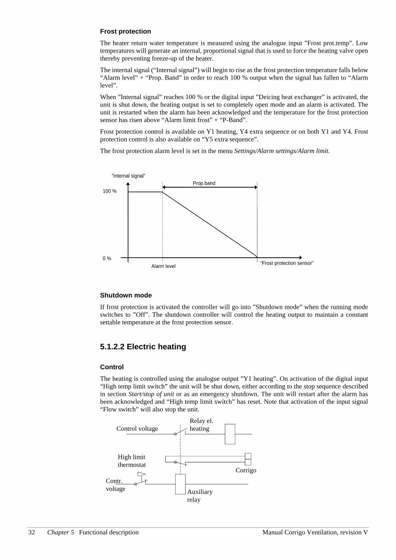
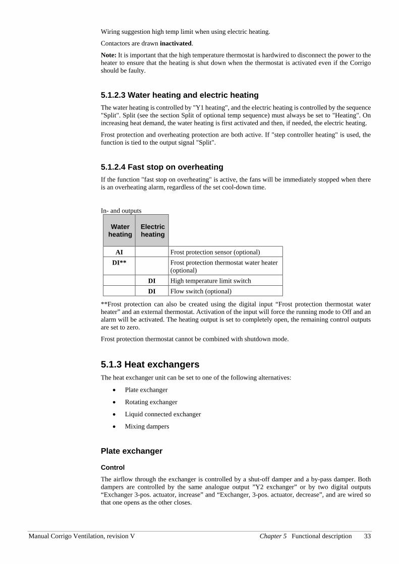
Control The heating is controlled using the analogue output ”Y1 heating”. On activation of the digital input “High temp limit switch” the unit will be shut down, either according to the stop sequence described in section Start/stop of unit or as an emergency shutdown. The unit will restart after the alarm has been acknowledged and “High temp limit switch” has reset. Note that activation of the input signal “Flow switch” will also stop the unit.
Relay el. heating Control voltage
Contr. voltage
High limit thermostat
Auxiliary relay
Corrigo
“Frost protection sensor”
“Internal signal”
0 %
100 % Prop.band
Alarm level
Manual Corrigo Ventilation, revision V Chapter 5 Functional description 33
Wiring suggestion high temp limit when using electric heating.
Contactors are drawn inactivated.
Note: It is important that the high temperature thermostat is hardwired to disconnect the power to the heater to ensure that the heating is shut down when the thermostat is activated even if the Corrigo should be faulty.
5.1.2.3 Water heating and electric heating The water heating is controlled by "Y1 heating", and the electric heating is controlled by the sequence "Split". Split (see the section Split of optional temp sequence) must always be set to "Heating". On increasing heat demand, the water heating is first activated and then, if needed, the electric heating.
Frost protection and overheating protection are both active. If "step controller heating" is used, the function is tied to the output signal "Split".
5.1.2.4 Fast stop on overheating If the function "fast stop on overheating" is active, the fans will be immediately stopped when there is an overheating alarm, regardless of the set cool-down time.
In- and outputs
Water heating
Electric heating
AI Frost protection sensor (optional) DI** Frost protection thermostat water heater
(optional) DI High temperature limit switch DI Flow switch (optional)
**Frost protection can also be created using the digital input “Frost protection thermostat water heater” and an external thermostat. Activation of the input will force the running mode to Off and an alarm will be activated. The heating output is set to completely open, the remaining control outputs are set to zero.
Frost protection thermostat cannot be combined with shutdown mode.
5.1.3 Heat exchangers The heat exchanger unit can be set to one of the following alternatives:
• Plate exchanger
• Rotating exchanger
• Liquid connected exchanger
• Mixing dampers
Plate exchanger
Control The airflow through the exchanger is controlled by a shut-off damper and a by-pass damper. Both dampers are controlled by the same analogue output ”Y2 exchanger” or by two digital outputs “Exchanger 3-pos. actuator, increase” and “Exchanger, 3-pos. actuator, decrease”, and are wired so that one opens as the other closes.
34 Chapter 5 Functional description Manual Corrigo Ventilation, revision V
Deicing Deicing is activated either when the digital signal ”Deicing” is activated or when the value of the analogue input ”Deicing temp” falls below the de-icing limit (-3°C), or when the analogue signal ”Deicing pressure guard” rises above the set value for the current pressure. It is deactivated when the digital signal is reset, or alternatively when the analogue signal exceeds/falls below the limit value plus a settable differential.
On deicing:
A PI-controller compares the deicing setpoint with the signal ”De-icing exchanger”. The lesser of the output signal from this controller and the output from the ordinary controller is used as output to the dampers.
Function to prevent the heat exchanger from freezing:
A temperature sensor, exhaust air, outdoor air or extra controller sensor can be used as a prevention sensor. It is possible to set a starting temperature. This represents both the minimum time that the function should be active, the supply air fan (SAF) and extract air fan (EAF) compensation, as well as the minimum time before the next prevention cycle should begin. While the cycle is active, ”De-icing” is shown in the display and in E tool©.
Rotating exchanger
Control Rotational speed is controlled by the analogue signal ”Y2 exchanger. A rotation sentinel can be connected to the digital input ”Rotation sentinel exchanger”. An alarm is generated if this input is activated at the same time as the analogue output signal is higher than 1.0 V.
Function to prevent the heat exchanger from freezing:
A temperature sensor, exhaust air, outdoor air or extra controller sensor can be used as a prevention sensor. It is possible to set a starting temperature. This represents both the minimum time that the function should be active, the supply air fan (SAF) and extract air fan (EAF) compensation, as well as the minimum time before the next prevention cycle should begin. While the cycle is active, ”De-icing” is shown in the display and in E tool©.
Liquid connected exchanger
Control A mixing valve in the exchanger circulation system is controlled by the analogue signal ”Y2 heat exchanger” or by two digital outputs “Exchanger 3-pos. actuator, increase” and “Exchanger, 3-pos. actuator, decrease”.
The circulation pump (digital output "Start/stop P1, liquid exchanger") is started as soon as the actuator control signal exceeds 0.1 V and is stopped when the valve has been closed for more than 5 minutes.
Deicing Deicing is activated either when the digital input signal ”Deicing exchanger” is activated or when the value of the analogue input ”Deicingtemp” falls below the deicing limit (-3°C). It is deactivated when the digital input is reset or the analogue input rises above the limit value plus a settable differential.
On deicing:
A PI-controller compares the deicing setpoint with the signal ”De-icing Exchanger”. The lesser of the output signal from this controller and the output from the ordinary controller is used as output to the actuator.
Manual Corrigo Ventilation, revision V Chapter 5 Functional description 35
Function to prevent the heat exchanger from freezing:
A temperature sensor, exhaust air, outdoor air or extra controller sensor can be used as a prevention sensor. It is possible to set a starting temperature. This represents both the minimum time that the function should be active, the supply air fan (SAF) and extract air fan (EAF) compensation, as well as the minimum time before the next prevention cycle should begin. While the cycle is active, ”De-icing” is shown in the display and in E tool©.
Outdoor temp control of exchanger Instead of using Y2 for analogue control of the heat exchanger it can be set to run on-off against outdoor temperature. The function controls a digital output “Exch control”, which is activated when the outdoor temperature falls below a set value.
Mixing dampers
Control The analogue output signal ”Exchanger Y2”, or the two digital output signals "Exchanger 3-position, increase" and "Exchanger 3-position, decrease", control two dampers for gradual mixing of outdoor air and recirculated air. In this mode the output signal decreases with increasing heat demand.
CO2 If demand controlled ventilation (see 5.4.2) is activated in combination with mixing dampers, and the CO2-value rises above the setpoint value, the dampers will let in more outdoor air. The function is controlled by a PI-controller. Factory settings: P-band 100ppm and I-time 100 seconds. These values can only be changed in E tool©.
CO2/VOC control can be used on ”Y2 exchanger” or ”Y4 extra sequence”. The control is selectable for use on Y2, Y4 or on both outputs.
Minimum limit An outdoor air minimum limit for can be set using the front panel. The limit value is settable between 0 and 100 %.
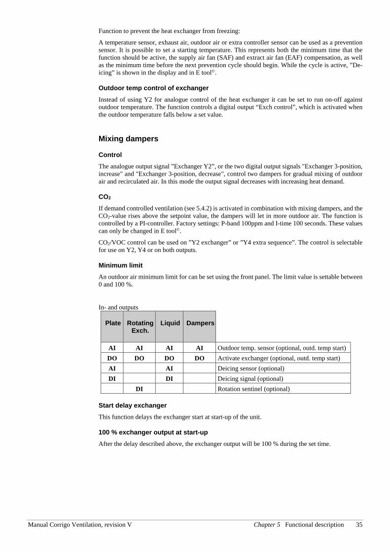
In- and outputs
Plate Rotating Exch.
Liquid Dampers
AI AI AI AI Outdoor temp. sensor (optional, outd. temp start) DO DO DO DO Activate exchanger (optional, outd. temp start) AI AI Deicing sensor (optional) DI DI Deicing signal (optional)
DI Rotation sentinel (optional)
Start delay exchanger This function delays the exchanger start at start-up of the unit.
100 % exchanger output at start-up After the delay described above, the exchanger output will be 100 % during the set time.
36 Chapter 5 Functional description Manual Corrigo Ventilation, revision V
5.1.4 Types of chillers
Step controller Heating / DX cooling As alternative or complement to the above mentioned analogue control, heating and cooling can be activated in steps. The internal signal is then used to activate digital outputs for control of the heaters/chillers. Up to four heater outputs and three cooler outputs can be configured. There are two possible modes:
Sequential control Each output step has individually settable on and off values in percent of the control signal. The number of steps is equal to the number of heater/chiller groups. Minimum on and off times can be set, i.e. the minimum time the step has to be inactive or active for a change to occur.
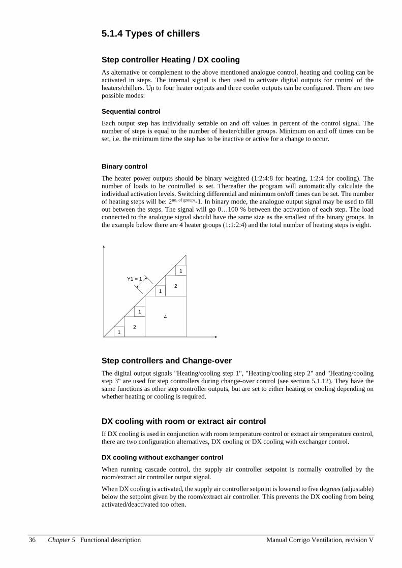
Binary control The heater power outputs should be binary weighted (1:2:4:8 for heating, 1:2:4 for cooling). The number of loads to be controlled is set. Thereafter the program will automatically calculate the individual activation levels. Switching differential and minimum on/off times can be set. The number of heating steps will be: 2no. of groups-1. In binary mode, the analogue output signal may be used to fill out between the steps. The signal will go 0…100 % between the activation of each step. The load connected to the analogue signal should have the same size as the smallest of the binary groups. In the example below there are 4 heater groups (1:1:2:4) and the total number of heating steps is eight.
Step controllers and Change-over The digital output signals "Heating/cooling step 1", "Heating/cooling step 2" and "Heating/cooling step 3" are used for step controllers during change-over control (see section 5.1.12). They have the same functions as other step controller outputs, but are set to either heating or cooling depending on whether heating or cooling is required.
DX cooling with room or extract air control If DX cooling is used in conjunction with room temperature control or extract air temperature control, there are two configuration alternatives, DX cooling or DX cooling with exchanger control.
DX cooling without exchanger control When running cascade control, the supply air controller setpoint is normally controlled by the room/extract air controller output signal.
When DX cooling is activated, the supply air controller setpoint is lowered to five degrees (adjustable) below the setpoint given by the room/extract air controller. This prevents the DX cooling from being activated/deactivated too often.
1
1
1
1
2
4
2
Y1 = 1
Manual Corrigo Ventilation, revision V Chapter 5 Functional description 37
DX cooling with exchanger control When running cascade control, the supply air controller setpoint is normally controlled by the room/extract air controller output signal.
When DX cooling is activated, the supply air controller setpoint is lowered to five degrees (adjustable) below the setpoint given by the room/extract air controller. This prevents the DX cooling from being activated/deactivated too often. If the supply air temperature falls below the setpoint given by the room/extract air controller, the heat exchanger output will be activated in order to try to maintain the supply air setpoint given by the room/extract air controller. The output uses P-control with a P-band of half the setpoint lowering (adjustable, 2.5°C as default). The setpoint given by the room/extract air controller cannot drop below the set min limit. When there is no longer a cooling demand, the supply air controller setpoint will return to the value given by the room/extract air controller.
Note: The function cannot be used if the exchanger signal controls a mixing damper.
Example:
The room controller gives a supply air setpoint of 16°C. If there is a cooling demand, the supply air controller setpoint is lowered to 11°C (16 – 5) and DX cooling is activated. Should the supply air temperature fall below 16°C, the exchanger output will be activated and reach 100 % output when the supply air temperature has fallen to 13.5°C (16 - 2.5).
Blocking of DX cooling at low outdoor temperature DX cooling can be blocked when the outdoor temperature is low. It is possible to block the three cooling steps individually or to block all DX cooling. The temperature limits are adjustable (+13°C default) and have a fixed one degree hysteresis.
When two DX cooling steps are used with binary function, the cooling effect is divided into three steps. The desired blocking level can be set individually for each of these steps.
When three DX cooling steps are used with binary function, the cooling effect is divided into seven steps. However, the controller still only has three blocking level settings. Therefore, Blocking step 1 will apply to binary steps 1 and 2, Blocking step 2 to binary steps 3 and 4, and Blocking step 3 to binary steps 5, 6 and 7.
Blocking of DX cooling at low supply air fan speed When DX cooling is used in conjunction with pressure controlled or flow controlled fans it is possible to block DX cooling if the supply air fan control signal falls below a preset values. For sequential control, the blocking level is individually settable for each DX cooling step.
When two DX cooling steps are used with binary function, the cooling effect is divided into three steps. The desired blocking level can be set individually for each of these steps.
When three DX cooling steps are used with binary function, the cooling effect is divided into seven steps. However, the controller still only has three blocking level settings. Therefore, Blocking step 1 will apply to binary steps 1 and 2, Blocking step 2 to binary steps 3 and 4, and Blocking step 3 to binary steps 5, 6 and 7.
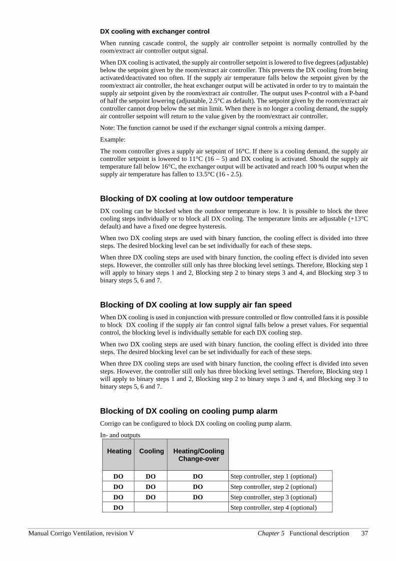
Blocking of DX cooling on cooling pump alarm Corrigo can be configured to block DX cooling on cooling pump alarm.
In- and outputs
Heating Cooling Heating/Cooling Change-over
DO DO DO Step controller, step 1 (optional) DO DO DO Step controller, step 2 (optional) DO DO DO Step controller, step 3 (optional) DO Step controller, step 4 (optional)
38 Chapter 5 Functional description Manual Corrigo Ventilation, revision V
Override of reduced speed for DX cooling Override to normal quantity of air for DX cooling when the unit runs on reduced quantity of air. The fans can be set to normal operation when cooling is required at high outdoor temperatures (e.g. >14°C, the same temperature limit as for blocking of DX cooling).
5.1.5 Support control Support control is normally used when room temperature control or extract air control has been configured. When extract air control is configured a room sensor must be installed. “Support control Heating” or “Support control Cooling” will run if Support control is configured, the running mode is in Off-state (timer control OFF and not in extended running) and if conditions call for support control (see below). Minimum run time is settable 0 to 720 minutes (FS= 20 minutes).
Support control can also be configured when supply air temperature control is used, if a room sensor is installed. The controller uses the configured min. (FS=15°C) and max. (FS=30°C) limitation values as support control setpoints. However, in this case the min. and max. limitation values cannot be changed. To change the values, temporarily configure room control, change the min. and max. values and then change back to supply air control.
Support control can also be configured to start only with the supply air fan. In this mode, the extract air fan is not active. This requires a digital output to be configured, which controls the recirculation damper to open completely so the supply air fan can circulate the air to and from the room. The digital output is called ”recirculation damper”.
Support control heating Demand for support control heating is when the room temperature is lower than the start value which is settable 0 to 30°C. The fans will run at the preset speed, the heater and the heat exchanger are controlled by the supply air temperature controller with the configured max limitation for the supply air (FS=30°C) as setpoint and the cooling is shut off (0%). Support control heating stops when the room temperature rises to the stop value and the minimum run time has been exceeded or the running mode changes to ”On”.
Support control cooling Demand for support control cooling is when the room temperature is higher than the start value which is settable 20 to 50°C. The fans will run at the preset speed, the heater and the heat exchanger are shut down (0 %) and the cooling is controlled by the supply air temperature controller with the configured minimum limitation (FS=15°C) as setpoint. Support control cooling stops when the temperature falls below the stop value and the minimum run time has been exceeded or the running mode changes to ”On”.
5.1.6 Free cooling This function is used during the summer to cool the building night-time using cool outdoor air, thereby reducing the need for cooling during the day and saving energy.
Free cooling requires an outdoor sensor (or an inlet temperature sensor) and either a room sensor or an extract air sensor. The outdoor sensor can be placed in the fresh air inlet duct.
Free cooling is only activated when all the start conditions are fulfilled.
Start conditions:
• Less than four days have passed since the unit was last in running mode.
• The outdoor temperature during the previous running period exceeded a set limit (22°C).
• It is between 00:00 and 07:00:00 in the day (settable).
• The timer outputs for "normal speed", "Extended running, Normal" and "External switch" are Off.
• A timer channel will be On sometime during the recently started 24 hours.
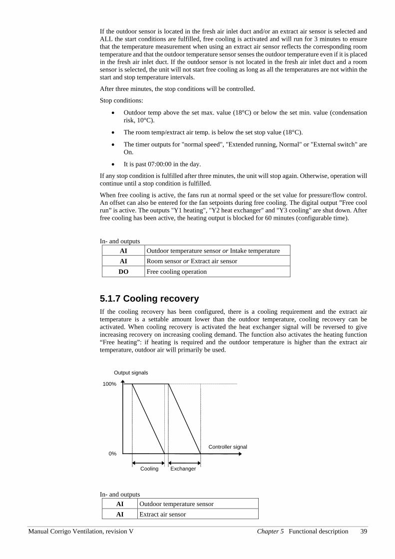
Manual Corrigo Ventilation, revision V Chapter 5 Functional description 39
If the outdoor sensor is located in the fresh air inlet duct and/or an extract air sensor is selected and ALL the start conditions are fulfilled, free cooling is activated and will run for 3 minutes to ensure that the temperature measurement when using an extract air sensor reflects the corresponding room temperature and that the outdoor temperature sensor senses the outdoor temperature even if it is placed in the fresh air inlet duct. If the outdoor sensor is not located in the fresh air inlet duct and a room sensor is selected, the unit will not start free cooling as long as all the temperatures are not within the start and stop temperature intervals.
After three minutes, the stop conditions will be controlled.
Stop conditions:
• Outdoor temp above the set max. value (18°C) or below the set min. value (condensation risk, 10°C).
• The room temp/extract air temp. is below the set stop value (18°C).
• The timer outputs for "normal speed", "Extended running, Normal" or "External switch" are On.
• It is past 07:00:00 in the day.
If any stop condition is fulfilled after three minutes, the unit will stop again. Otherwise, operation will continue until a stop condition is fulfilled.
When free cooling is active, the fans run at normal speed or the set value for pressure/flow control. An offset can also be entered for the fan setpoints during free cooling. The digital output ”Free cool run” is active. The outputs "Y1 heating", "Y2 heat exchanger" and "Y3 cooling" are shut down. After free cooling has been active, the heating output is blocked for 60 minutes (configurable time).
In- and outputs AI Outdoor temperature sensor or Intake temperature AI Room sensor or Extract air sensor DO Free cooling operation
5.1.7 Cooling recovery If the cooling recovery has been configured, there is a cooling requirement and the extract air temperature is a settable amount lower than the outdoor temperature, cooling recovery can be activated. When cooling recovery is activated the heat exchanger signal will be reversed to give increasing recovery on increasing cooling demand. The function also activates the heating function “Free heating”: if heating is required and the outdoor temperature is higher than the extract air temperature, outdoor air will primarily be used.
Output signals
Controller signal 0%
100%
Exchanger Cooling
In- and outputs AI Outdoor temperature sensor AI Extract air sensor
40 Chapter 5 Functional description Manual Corrigo Ventilation, revision V
5.1.8 Enthalpy control Calculating the enthalpy means to calculate the energy content of the air, taking into consideration both the temperature and the air humidity. The value is given in energy per kilogram air (kJ/kg). If enthalpy control is configured, the enthalpy is calculated both indoors and outdoors. If enthalpy control is configured, enthalpy is calculated both outdoors and for the extract air. If the enthalpy is higher outdoors than in the extract air, the recirculation damper function will be overridden to increase the recirculation. The function is not active when using free cooling, in which case outdoor air is used for cooling the room instead. In order for the enthalpy calculation to be made the functions enthalpy control and cooling recovery must be active, and four sensors are required:
In- and outputs AI Outdoor temperature sensor AI Outdoor humidity sensor AI Room/Extract air temperature sensor AI Room humidity sensor
5.1.9 Heat exchanger efficiency monitoring
General The function calculates the heat exchanger temperature efficiency in percent when the output signal to the exchanger is higher than 5 % and the outdoor temperature is lower than 10°C.
When the control signal is lower than 5 % or the outdoor temperature is higher than 10°C the display will show 0 %.
The heat exchanger efficiency is calculated using the following formula:
Option 1: Efficiency = (Extract air temp – Exhaust air temp) / (Extract air temp – Outdoor temp) * 100
Option 2: Efficiency = (Efficiency temp – Outdoor temp) / (Extract air temp – Outdoor temp) * 100
Alarm An alarm is activated if the efficiency falls below the set alarm level (50 %).
In- and outputs AI Outdoor temperature sensor AI Extract air sensor AI Exhaust air sensor AI Efficiency temperature sensor
The efficiency temperature sensor should be placed after the heat exchanger but before the heater. It will then replace the exhaust air temperature sensor.
5.1.10 External setpoint An external setpoint device, e.g. TBI-PT1000 or TG-R4/PT1000 can be connected. The setpoint device must follow the PT1000 resistance curve. The unit is connected to the analogue input signal ”Extra temperature sensor 1”. The function must be activated in the menu ”Configuration/External setpoint”. The setting range can be min/max limited via a setting in the controller. The factory setting is min: +12, max: +30.
In- and outputs AI Extra temperature sensor 1
Manual Corrigo Ventilation, revision V Chapter 5 Functional description 41
5.1.11 Recirculation Recirculation is a function for distributing the air in the room using the supply air fan. The function can be used even when there is no heating or cooling demand. When using recirculation control, the extract air fan stops (but can also be set to run) and a recirculation damper opens which allows the air to circulate through the unit.
Recirculation is activated either via a digital input signal or by connecting it to "Timer output 5". If timer output for normal/reduced speed is activated during recirculation via ”Timer output 5”, normal/reduced speed gets priority. If timer output for normal/reduced speed is activated during recirculation via a digital input, recirculation gets priority.
Either a digital output (Recirculation damper) or an analogue output (Y4 Extra sequence) can be used as an output signal. When Y4 Extra sequence is used, the damper will become modulating.
Recirculation control can be configured as either air circulation (temperature control inactive) or air circulation with temperature control. (Only heating, only cooling or both heating and cooling). Recirculation control has its own setpoint. However, the other settings are the same as for normal operation, i. e. if normal operation has been configured as room control, room control will also be used during recirculation.
The recirculation setpoint can be configured as constant or offset. Constant means that the recirculation setpoint will be used. Offset is based on an offset from the supply air setpoint.
To lower the temperature, it is possible to configure free cooling to be used during recirculation, if the conditions for free cooling are fulfilled. Then, the recirculation damper closes, the supply and extract air dampers open and the extract air fan starts (the supply air fan also starts, if it is not already running). If the free cooling function is not configured for recirculation control and you want to cool down the supply air via a low recirculation setpoint, the cooling battery will be used. A max. room temperature can be configured for recirculation control. If the room temperature rises above the set value (FS 25°C), recirculation will be stopped. When the room temperature has fallen 1 K below the set max limit, recirculation will start again if the start conditions are still fulfilled.
When running frequency controlled fans and using recirculation control you can, depending on the type of fan control, configure a special pressure/flow offset for the setpoint or a manual output signal for the supply air fan.
5.1.12 Change-over Change-over is a function for installations with 2-pipe systems. It makes it possible to use the same pipe for both heating and cooling, depending on whether heating or cooling is required.
A special analogue output signal, "Y1 heating/Y3 cooling", is used for Change-over control. Switching between heating and cooling can be done in two ways. A digital Change-over input signal is normally used. Open contact gives heating control and closed contact gives cooling control. If the input has not been configured, change-over is handled by the internal controller signal. The output signal will follow the two regular output signals "Y1 heating" and "Y3 cooling". For heating control, the digital outputs ”Heating activate” and ”Heat step 1-4” are active. For cooling control ”Cooling activate” and ”Cool step 1-3” are active.
If frost protection sensor has been configured, it will function in the usual way when heating is active. However, when cooling is active, it will only be used for indicating temperature.
Three digital output signals, "Heat/Cool Step 1", "Heat/Cool Step 2" and "Heat/Cool Step 3", are also connected with change-over. The signals can be used for reversing a step controlled heating pump etc. See also section 5.1.4 Step controller Heating/ DX cooling.
The change-over function can be split if needed. If so, set the analogue output to “Split” and select the function Y1 heating/Y3 cooling.
A digital function called “Split sequence” is connected to the split signal. It is active when the corresponding analogue signal exceeds 0.1 V.
42 Chapter 5 Functional description Manual Corrigo Ventilation, revision V
5.1.13 Extra temperature sensor The input signals ”Extra Sensor Temp 1”, ”Extra Sensor Temp 2”, ”...”, ”Extra Sensor Temp 5”, can be used to add extra temperature sensors for supervision of temperatures that are not related to any control functions. Each sensor has three alarms tied to it: High temperature, Low temperature and Sensor error. “Extra temperature sensor 1” should be used for external setpoint input. “Extra Sensor Temp 1” should be used for external setpoint input.
5.1.14 Extra flow sensors supply air and extract air The input signals ”Extra SAF Pressure” and ”Extra EAF Pressure” can be used to display the flow in the supply air and extract air ducts. The K- and X-constants for each fan are used to calculate the flow.
5.2 Extra controller An independent temperature control circuit for control of for example after-heaters. The circuit can be configured to heating or cooling. It has an analogue input signal for temperature sensors and an analogue output signal 0…10 V. There is also a digital output signal which is activated when the analogue output signal is above 1 V and deactivated when the analogue signal is below 0.1 V. The circuit can be configured to be active all the time or to be active only when the main unit is running at normal speed.
The extra controller can also be used for humidity control. The cooling battery will be used for dehumidification if the room/extract air humidity is too high. The function uses the sensor “Extra unit temp” and is placed immediately after the cooling battery. The function also requires use of a room humidity or extract air humidity sensor.
Example:
If the room humidity exceeds the setpoint for the function, the cooling battery will be controlled by the external controller. The heater is controlled normally. When the room humidity falls below the setpoint once more, the cooling control will return to normal control. A hysteresis of 1 % is added to the function.
The function can be used for ”Cascaded room temperature control”, ”Cascade connected extract air temperature control”, ”Outdoor compensated room temperature control” as well as ”Outdoor compensated extract air control”.
An alarm will be triggered if ”Extra controller” is in manual position or if a sensor error occurs.
5.3 Humidity control
General Humidity control can be configured as Humidification, Dehumidification or both Humidification and Dehumidification.
Two humidity sensors can be connected, a room sensor for control and an optional duct sensor for maximum limiting. The limit sensor can be omitted.
The humidity control is handled by a PI-controller.
The humidity sensors must give 0…10 V DC for 0…100 % RH.
Humidification An analogue output is used to control a humidifier. The output will increase on decreasing humidity. A digital output can also be used to start a humidifier.
Maximum limitation function using duct humidity sensor:
Manual Corrigo Ventilation, revision V Chapter 5 Functional description 43
If the maximum limitation is 80 % RH and the hysteresis is 20 % RH, the controller output signal will begin decreasing at 60 % RH. When halfway to 80 % RH (i.e. when at 70 % RH), half the output signal will be damped. If the humidity in the duct still reaches 80 % RH, the entire output signal will be damped.
Dehumidification An analogue output is used to control a dehumidifier. The output will increase on increasing humidity. A digital output can also be used to start a dehumidifier.
Humidification/dehumidification An analogue output is used to control a humidifier. The output will increase on decreasing humidity.
The cooling output Y3 will be activated for dehumidification through condensation. The output will increase on increasing humidity. This signal overrides the cooling signal from the temperature controller so the output can be activated for dehumidification even if the temperature controller demand is zero.
For good temperature control when using cooling for dehumidification it is important that the cooler is placed first in the air stream so that the exchanger and heater can be used to reheat the air after dehumidification.
Digital humidity signal A digital output signal, "Dehumidification/Humidification", can be used for on/off control of humidifiers/dehumidifiers. The output signal has an activation value and a deactivation value which are connected to the humidity controller output. The signal is activated when the humidity controller output rises above the set activation value and is deactivated when the humidity controller output drops below the set deactivation value.
If a start signal is needed for a cooling unit or a magnetic valve for DX dehumidification, the digital output signal “Start P1-Cooling” should be used. In this case, the “pump” stop delay should be set to 0 s.
Inputs and outputs AI Room humidity sensor AI Duct humidity sensor AO Humidity control output 0…10 V DC DO Dehumidification/Humidification
5.4 Fan control
General Fans can be 1-speed, 2-speed or variable speed via a frequency converter.
1-speed fans are controlled using the digital outputs "Start SAF-Normal" and "Start EAF-Normal".
2-speed fans are controlled using the digital outputs "Start SAF-Normal" and "Start EAF-Normal" as well as "Start SAF-reduced" and "Start EAF-reduced" giving normal and reduced speed respectively.
Variable speed control uses an analogue output per fan for controlling a frequency converter. There are two setpoints for each fan, "Normal" and "Reduced". Pressure or air flow control can be used.
Variable speed fans can also be configured to be run with fixed output values.
Compensation curve When running pressure/flow control or manual frequency control, it is also possible to for the pressure/flow or output to be temperature compensated.
44 Chapter 5 Functional description Manual Corrigo Ventilation, revision V
This compensation can be made depending on supply air, extract air, room or outdoor temperature.
It is possible to compensate either one or both of the fans at the same time. It is possible to set which fan should then be compensated, the supply or extract air fan.
Crosswise interlock Crosswise interlock of fans can be configured, which e.g. means that if one fan stops, the other fan will also stop.
Timer outputs, interlock at low outdoor temperatures The fans are normally controlled by the timer channels for normal and reduced speed. At very low outdoor temperatures, "2-speed fans" or "pressure controlled fans" can be forced to "reduced speed". The limit temperature is settable and the function has a differential of 2K.
Normal and reduced speed Units with 2-speed or pressure control fans are always started at "reduced speed". After a settable time, Corrigo switches to "Normal speed" if normal speed is valid at start-up. When 2-speed fans are switched from "Reduced speed" to "Normal speed", "Reduced speed" is first disengaged. About 2 sec later, "Normal speed" is activated.
When Corrigo switches from "Normal speed" to "Reduced speed", there is a settable retardation time from disengagement to activation. See the section Retardation time.
The extract air fan and the supply air fan have individual start and stop delays which are normally set so that the extract air fan is started before the supply air fan. If there are not enough digital outputs for individual control, both fans will have to be started using the signal for the supply air fan, and the delay be created using an external time relay.
5.4.1 Pressure control
Frequency control pressure During pressure control, two separate analogue output signals are used for supply and extract air and two separate analogue input signals for supply and extract air for pressure transmitters. The fan speeds are controlled via frequency converters, thereby maintaining constant pressure. The pressure transmitter inputs are scalable using “Min volt input (Vmin)” and “Max volt input (Vmax)”.
A digital activation signal is normally used for each fan (“SAF freq conv start” and “EAF freq conv start”), for sending a start signal to the frequency converters. The start signal is activated as long as the fan is expected to be running.
For the supply and extract air fans, there are two individually settable setpoint values, one corresponding to normal speed and one corresponding to reduced speed. Changing between the two setpoint values is done using the timer channels for normal and reduced speed or using digital input signals ("Extended Operation, normal" and "Extended Operation, reduced").
Outdoor compensation When running pressure control, it is also possible to outdoor compensate the pressure setpoint value.
The outdoor compensation is linear and is set using two parameter pairs which give the value of the compensation at two different outdoor temperatures. The compensation can be positive or negative.
The outdoor compensation is set in the menu Actual/Setpoint.
Using E tool©, you can also choose to only outdoor compensate the pressure value of the supply air fan. In that case, the extract air fan is controlled with constant flow, independent of the outdoor temperature.
The compensation can be selected to apply to both normal and reduced speed, or for normal speed only (factory setting = both speeds).
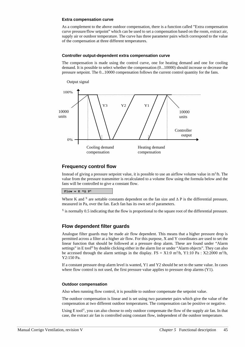
Manual Corrigo Ventilation, revision V Chapter 5 Functional description 45
Extra compensation curve As a complement to the above outdoor compensation, there is a function called ”Extra compensation curve pressure/flow setpoint” which can be used to set a compensation based on the room, extract air, supply air or outdoor temperature. The curve has three parameter pairs which correspond to the value of the compensation at three different temperatures.
Controller output-dependent extra compensation curve The compensation is made using the control curve, one for heating demand and one for cooling demand. It is possible to select whether the compensation (0...10000) should increase or decrease the pressure setpoint. The 0...10000 compensation follows the current control quantity for the fans.
Regulator- utsignal
Y1 Y2 Y3
Utsignal
0%
100%
Kompensation vid kylbehov
Kompensation vid värmebehov
Frequency control flow Instead of giving a pressure setpoint value, it is possible to use an airflow volume value in m3/h. The value from the pressure transmitter is recalculated to a volume flow using the formula below and the fans will be controlled to give a constant flow.
Flow = K *∆ PX
Where K and X are settable constants dependent on the fan size and ∆ P is the differential pressure, measured in Pa, over the fan. Each fan has its own set of parameters. X is normally 0.5 indicating that the flow is proportional to the square root of the differential pressure.
Flow dependent filter guards Analogue filter guards may be made air flow dependent. This means that a higher pressure drop is permitted across a filter at a higher air flow. For this purpose, X and Y coordinates are used to set the linear function that should be followed at a pressure drop alarm. These are found under “Alarm settings” in E tool© by double clicking either in the alarm list or under “Alarm objects”. They can also be accessed through the alarm settings in the display. FS = X1:0 m3/h, Y1:10 Pa : X2:2000 m3/h, Y2:150 Pa.
If a constant pressure drop alarm level is wanted, Y1 and Y2 should be set to the same value. In cases where flow control is not used, the first pressure value applies to pressure drop alarms (Y1).
Outdoor compensation Also when running flow control, it is possible to outdoor compensate the setpoint value.
The outdoor compensation is linear and is set using two parameter pairs which give the value of the compensation at two different outdoor temperatures. The compensation can be positive or negative.
Using E tool©, you can also choose to only outdoor compensate the flow of the supply air fan. In that case, the extract air fan is controlled using constant flow, independent of the outdoor temperature.
Output signal
Cooling demand compensation
Heating demand compensation
Controller output
10000 units
10000 units
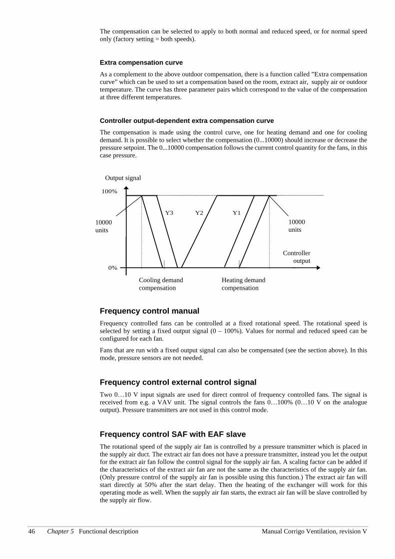
46 Chapter 5 Functional description Manual Corrigo Ventilation, revision V
The compensation can be selected to apply to both normal and reduced speed, or for normal speed only (factory setting = both speeds).
Extra compensation curve As a complement to the above outdoor compensation, there is a function called ”Extra compensation curve” which can be used to set a compensation based on the room, extract air, supply air or outdoor temperature. The curve has three parameter pairs which correspond to the value of the compensation at three different temperatures.
Controller output-dependent extra compensation curve The compensation is made using the control curve, one for heating demand and one for cooling demand. It is possible to select whether the compensation (0...10000) should increase or decrease the pressure setpoint. The 0...10000 compensation follows the current control quantity for the fans, in this case pressure.
Regulator- utsignal
Y1 Y2 Y3
Utsignal
0%
100%
Kompensation vid kylbehov
Kompensation vid värmebehov
Frequency control manual Frequency controlled fans can be controlled at a fixed rotational speed. The rotational speed is selected by setting a fixed output signal (0 – 100%). Values for normal and reduced speed can be configured for each fan.
Fans that are run with a fixed output signal can also be compensated (see the section above). In this mode, pressure sensors are not needed.
Frequency control external control signal Two 0…10 V input signals are used for direct control of frequency controlled fans. The signal is received from e.g. a VAV unit. The signal controls the fans 0…100% (0…10 V on the analogue output). Pressure transmitters are not used in this control mode.
Frequency control SAF with EAF slave The rotational speed of the supply air fan is controlled by a pressure transmitter which is placed in the supply air duct. The extract air fan does not have a pressure transmitter, instead you let the output for the extract air fan follow the control signal for the supply air fan. A scaling factor can be added if the characteristics of the extract air fan are not the same as the characteristics of the supply air fan. (Only pressure control of the supply air fan is possible using this function.) The extract air fan will start directly at 50% after the start delay. Then the heating of the exchanger will work for this operating mode as well. When the supply air fan starts, the extract air fan will be slave controlled by the supply air flow.
Output signal
Cooling demand compensation
Heating demand compensation
Controller output
10000 units
10000 units
Manual Corrigo Ventilation, revision V Chapter 5 Functional description 47
Frequency control EAF with SAF slave The rotational speed of the extract air fan is controlled by a pressure transmitter which is placed in the extract air duct. The supply air fan has no pressure transmitter. Instead, the supply air fan output is made to follow the extract air fan control signal. A scaling factor can be added if the supply air fan characteristics are not the same as the characteristics of the extract air fan (only pressure control of the extract air fan is possible using this function).
Frequency control SAF with flow control EAF The rotational speed of the supply air fan is controlled by a pressure transmitter which is placed in the supply air duct. The extract air fan is controlled by the supply air flow, in order to achieve a balanced ventilation. A pressure transmitter which is placed in the supply air fan cone ("Pressure transmitter SAF 2") gives a measured value of the present supply air flow. A corresponding pressure transmitter is placed in the extract air fan cone and gives a measured value of the extract air flow.
The supply air flow is the setpoint used for control of the extract air fan. A scaling factor can be added if the extract air fan does not have the same characteristics as the supply air fan.
Frequency control EAF with flow control SAF The rotational speed of the extract air fan is controlled by a pressure transmitter which is placed in the extract air duct. The supply air fan is controlled by the extract air duct flow in order to achieve a balanced ventilation. A pressure transmitter placed in the extract air fan cone (“Extra SAF Pressure”) provides a measurement of the current extract air flow. A corresponding pressure transmitter is placed in the supply air fan cone, providing a measurement of the supply air flow.
The supply air fan is controlled using the extract air flow as a setpoint. A scaling factor can be added if the supply air fan does not have the same characteristics as the extract air fan.
Slave controlled and flow controlled EAF depending on differential pressure across exchanger This function enables letting the extract air fan follow the differential pressure across the heat exchanger. The extract air fan setpoint is calculated as follows: The extract air fan flow setpoint = Flow across exchanger - (Supply air fan flow setpoint - Extract air fan flow setpoint). The function works with “Frequency control air flow” and “Frequency control SAF (Pa) with EAF flow control”.
Frequency control SAF and EAF with external flow setpoint This signal can be used to control the SAF and EAF flow setpoints from an external VAV system if the ”Frequency control external” fan type is used.
If this signal is configured as an analogue input signal, the flow setpoint for the SAF and EAF will be controlled in normal speed.
The signal can be configured by using scaling: Min volt input (Vmin)/Min flow and Max volt input (Vmax)/Max flow.
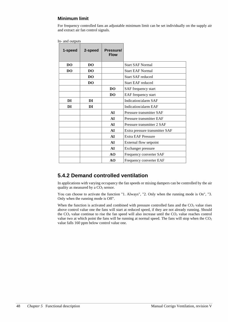
48 Chapter 5 Functional description Manual Corrigo Ventilation, revision V
Minimum limit For frequency controlled fans an adjustable minimum limit can be set individually on the supply air and extract air fan control signals.
In- and outputs
1-speed 2-speed Pressure/ Flow
DO DO Start SAF Normal DO DO Start EAF Normal
DO Start SAF reduced DO Start EAF reduced DO SAF frequency start DO EAF frequency start
DI DI Indication/alarm SAF DI DI Indication/alarm EAF
AI Pressure transmitter SAF AI Pressure transmitter EAF AI Pressure transmitter 2 SAF AI Extra pressure transmitter SAF AI Extra EAF Pressure AI External flow setpoint AI Exchanger pressure AO Frequency converter SAF AO Frequency converter EAF
5.4.2 Demand controlled ventilation In applications with varying occupancy the fan speeds or mixing dampers can be controlled by the air quality as measured by a CO2 sensor.
You can choose to activate the function "1. Always", "2. Only when the running mode is On", "3. Only when the running mode is Off".
When the function is activated and combined with pressure controlled fans and the CO2 value rises above control value one the fans will start at reduced speed, if they are not already running. Should the CO2 value continue to rise the fan speed will also increase until the CO2 value reaches control value two at which point the fans will be running at normal speed. The fans will stop when the CO2 value falls 160 ppm below control value one.
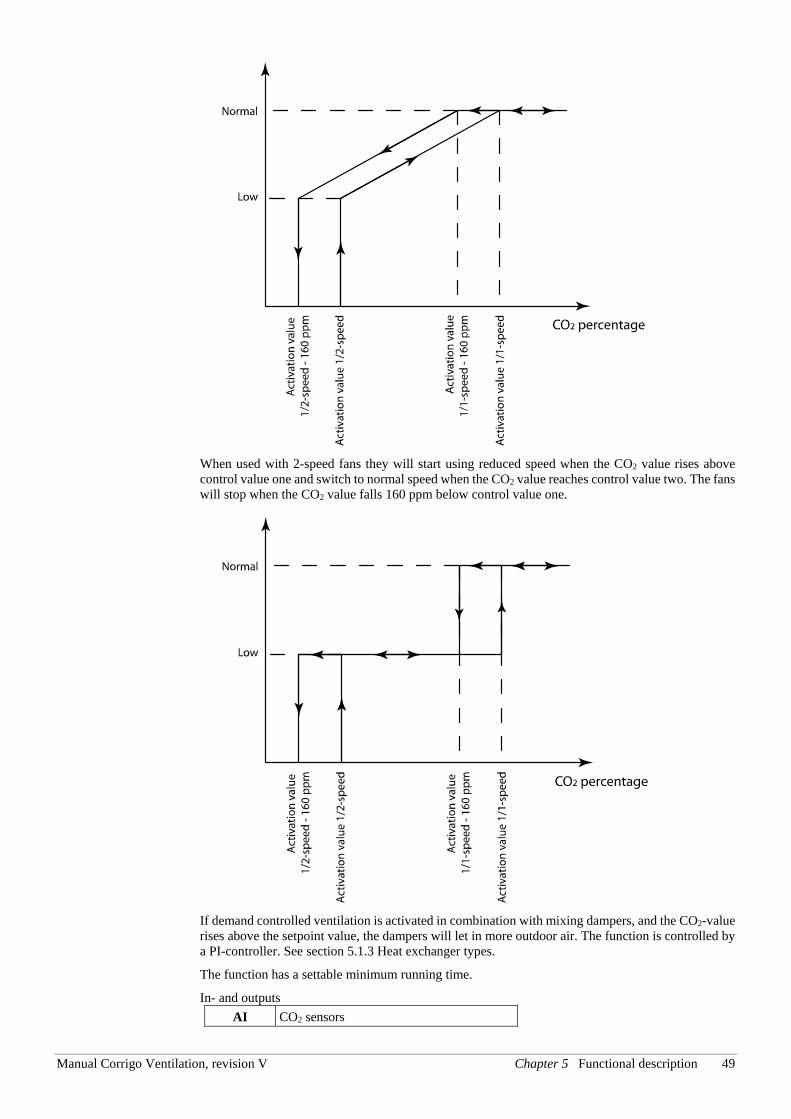
Manual Corrigo Ventilation, revision V Chapter 5 Functional description 49
When used with 2-speed fans they will start using reduced speed when the CO2 value rises above control value one and switch to normal speed when the CO2 value reaches control value two. The fans will stop when the CO2 value falls 160 ppm below control value one.
If demand controlled ventilation is activated in combination with mixing dampers, and the CO2-value rises above the setpoint value, the dampers will let in more outdoor air. The function is controlled by a PI-controller. See section 5.1.3 Heat exchanger types.
The function has a settable minimum running time.
In- and outputs AI CO2 sensors
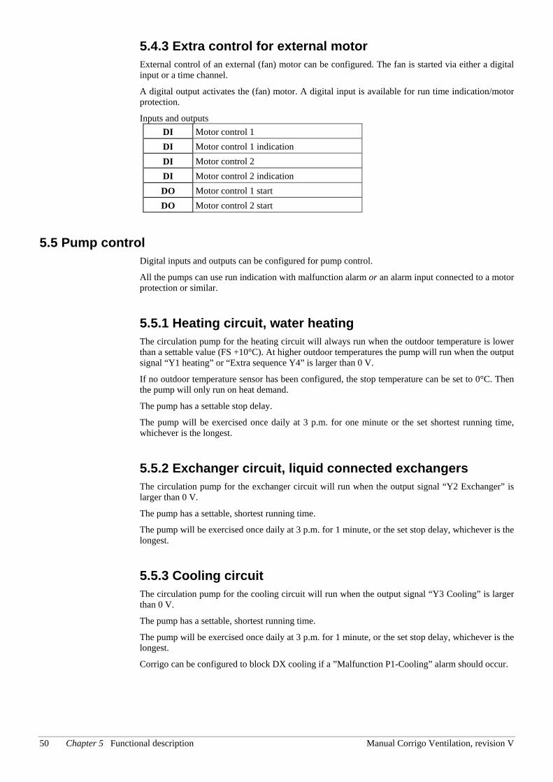
50 Chapter 5 Functional description Manual Corrigo Ventilation, revision V
5.4.3 Extra control for external motor External control of an external (fan) motor can be configured. The fan is started via either a digital input or a time channel.
A digital output activates the (fan) motor. A digital input is available for run time indication/motor protection.
Inputs and outputs DI Motor control 1 DI Motor control 1 indication DI Motor control 2 DI Motor control 2 indication DO Motor control 1 start DO Motor control 2 start
5.5 Pump control Digital inputs and outputs can be configured for pump control.
All the pumps can use run indication with malfunction alarm or an alarm input connected to a motor protection or similar.
5.5.1 Heating circuit, water heating The circulation pump for the heating circuit will always run when the outdoor temperature is lower than a settable value (FS +10°C). At higher outdoor temperatures the pump will run when the output signal “Y1 heating” or “Extra sequence Y4” is larger than 0 V.
If no outdoor temperature sensor has been configured, the stop temperature can be set to 0°C. Then the pump will only run on heat demand.
The pump has a settable stop delay.
The pump will be exercised once daily at 3 p.m. for one minute or the set shortest running time, whichever is the longest.
5.5.2 Exchanger circuit, liquid connected exchangers The circulation pump for the exchanger circuit will run when the output signal “Y2 Exchanger” is larger than 0 V.
The pump has a settable, shortest running time.
The pump will be exercised once daily at 3 p.m. for 1 minute, or the set stop delay, whichever is the longest.
5.5.3 Cooling circuit The circulation pump for the cooling circuit will run when the output signal “Y3 Cooling” is larger than 0 V.
The pump has a settable, shortest running time.
The pump will be exercised once daily at 3 p.m. for 1 minute, or the set stop delay, whichever is the longest.
Corrigo can be configured to block DX cooling if a ”Malfunction P1-Cooling” alarm should occur.
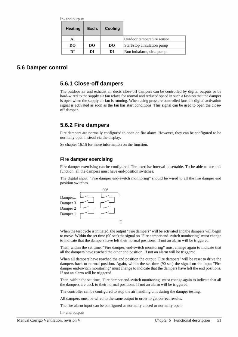
Manual Corrigo Ventilation, revision V Chapter 5 Functional description 51
In- and outputs
Heating Exch. Cooling
AI Outdoor temperature sensor DO DO DO Start/stop circulation pump DI DI DI Run ind/alarm, circ. pump
5.6 Damper control
5.6.1 Close-off dampers The outdoor air and exhaust air ducts close-off dampers can be controlled by digital outputs or be hard-wired to the supply air fan relays for normal and reduced speed in such a fashion that the damper is open when the supply air fan is running. When using pressure controlled fans the digital activation signal is activated as soon as the fan has start conditions. This signal can be used to open the close-off damper.
5.6.2 Fire dampers Fire dampers are normally configured to open on fire alarm. However, they can be configured to be normally open instead via the display.
Se chapter 16.15 for more information on the function.
Fire damper exercising Fire damper exercising can be configured. The exercise interval is settable. To be able to use this function, all the dampers must have end-position switches.
The digital input: "Fire damper end-switch monitoring" should be wired to all the fire damper end position switches.
When the test cycle is initiated, the output "Fire dampers" will be activated and the dampers will begin to move. Within the set time (90 sec) the signal on "Fire damper end-switch monitoring" must change to indicate that the dampers have left their normal positions. If not an alarm will be triggered.
Then, within the set time, ”Fire damper, end-switch monitoring” must change again to indicate that all the dampers have reached the other end position. If not an alarm will be triggered.
When all dampers have reached the end position the output "Fire dampers" will be reset to drive the dampers back to normal position. Again, within the set time (90 sec) the signal on the input "Fire damper end-switch monitoring" must change to indicate that the dampers have left the end positions. If not an alarm will be triggered.
Then, within the set time, "Fire damper end-switch monitoring" must change again to indicate that all the dampers are back to their normal positions. If not an alarm will be triggered.
The controller can be configured to stop the air handling unit during the damper testing.
All dampers must be wired to the same output in order to get correct results.
The fire alarm input can be configured as normally closed or normally open.
In- and outputs
90°
Damper... Damper 3 Damper 2 Damper 1
i
E
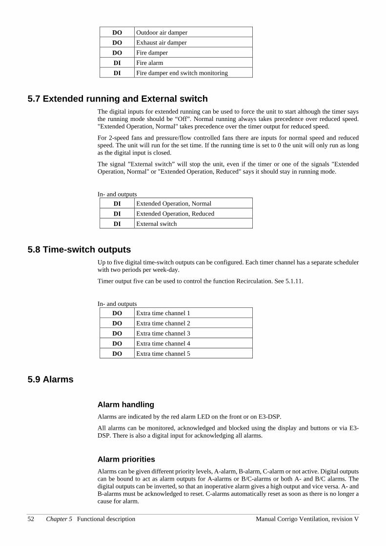
52 Chapter 5 Functional description Manual Corrigo Ventilation, revision V
DO Outdoor air damper DO Exhaust air damper DO Fire damper DI Fire alarm DI Fire damper end switch monitoring
5.7 Extended running and External switch The digital inputs for extended running can be used to force the unit to start although the timer says the running mode should be “Off”. Normal running always takes precedence over reduced speed. "Extended Operation, Normal" takes precedence over the timer output for reduced speed.
For 2-speed fans and pressure/flow controlled fans there are inputs for normal speed and reduced speed. The unit will run for the set time. If the running time is set to 0 the unit will only run as long as the digital input is closed.
The signal ”External switch” will stop the unit, even if the timer or one of the signals "Extended Operation, Normal" or "Extended Operation, Reduced" says it should stay in running mode.
In- and outputs DI Extended Operation, Normal DI Extended Operation, Reduced DI External switch
5.8 Time-switch outputs Up to five digital time-switch outputs can be configured. Each timer channel has a separate scheduler with two periods per week-day.
Timer output five can be used to control the function Recirculation. See 5.1.11.
In- and outputs DO Extra time channel 1 DO Extra time channel 2 DO Extra time channel 3 DO Extra time channel 4 DO Extra time channel 5
5.9 Alarms
Alarm handling Alarms are indicated by the red alarm LED on the front or on E3-DSP.
All alarms can be monitored, acknowledged and blocked using the display and buttons or via E3-DSP. There is also a digital input for acknowledging all alarms.
Alarm priorities Alarms can be given different priority levels, A-alarm, B-alarm, C-alarm or not active. Digital outputs can be bound to act as alarm outputs for A-alarms or B/C-alarms or both A- and B/C alarms. The digital outputs can be inverted, so that an inoperative alarm gives a high output and vice versa. A- and B-alarms must be acknowledged to reset. C-alarms automatically reset as soon as there is no longer a cause for alarm.
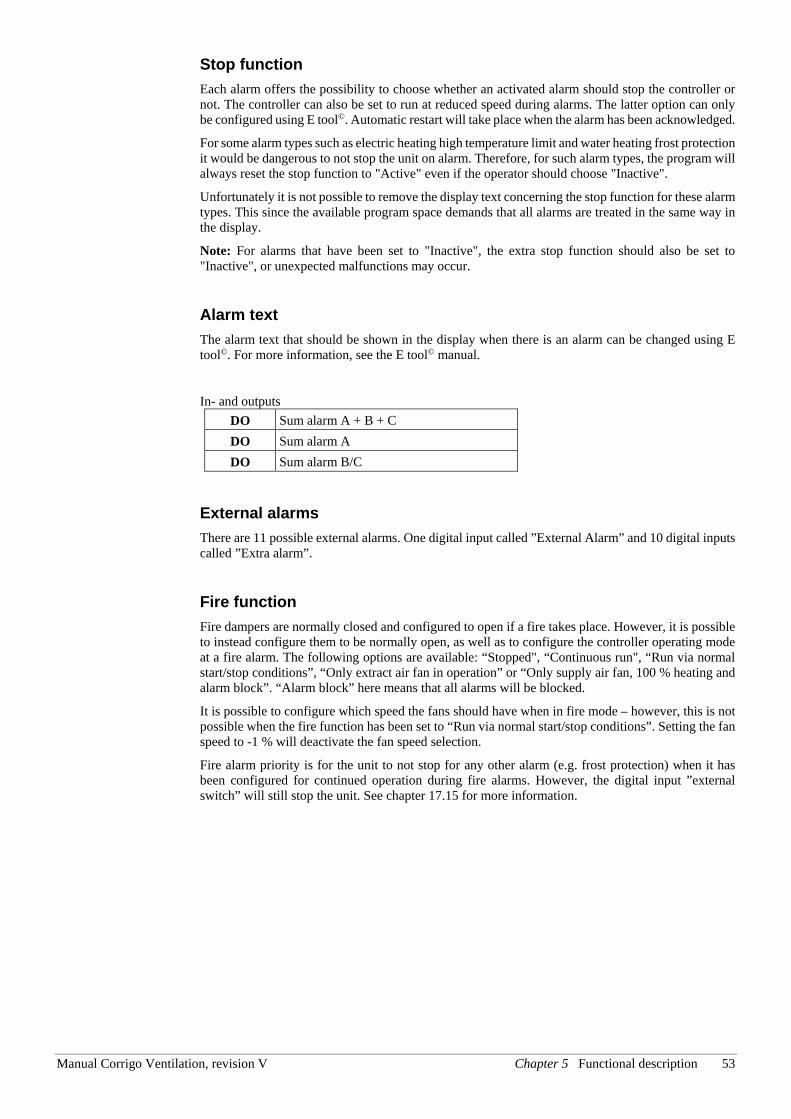
Manual Corrigo Ventilation, revision V Chapter 5 Functional description 53
Stop function Each alarm offers the possibility to choose whether an activated alarm should stop the controller or not. The controller can also be set to run at reduced speed during alarms. The latter option can only be configured using E tool©. Automatic restart will take place when the alarm has been acknowledged.
For some alarm types such as electric heating high temperature limit and water heating frost protection it would be dangerous to not stop the unit on alarm. Therefore, for such alarm types, the program will always reset the stop function to "Active" even if the operator should choose "Inactive".
Unfortunately it is not possible to remove the display text concerning the stop function for these alarm types. This since the available program space demands that all alarms are treated in the same way in the display.
Note: For alarms that have been set to "Inactive", the extra stop function should also be set to "Inactive", or unexpected malfunctions may occur.
Alarm text The alarm text that should be shown in the display when there is an alarm can be changed using E tool©. For more information, see the E tool© manual.
In- and outputs DO Sum alarm A + B + C DO Sum alarm A DO Sum alarm B/C
External alarms There are 11 possible external alarms. One digital input called ”External Alarm” and 10 digital inputs called ”Extra alarm”.
Fire function Fire dampers are normally closed and configured to open if a fire takes place. However, it is possible to instead configure them to be normally open, as well as to configure the controller operating mode at a fire alarm. The following options are available: “Stopped", “Continuous run", “Run via normal start/stop conditions”, “Only extract air fan in operation” or “Only supply air fan, 100 % heating and alarm block”. “Alarm block” here means that all alarms will be blocked.
It is possible to configure which speed the fans should have when in fire mode – however, this is not possible when the fire function has been set to “Run via normal start/stop conditions”. Setting the fan speed to -1 % will deactivate the fan speed selection.
Fire alarm priority is for the unit to not stop for any other alarm (e.g. frost protection) when it has been configured for continued operation during fire alarms. However, the digital input ”external switch” will still stop the unit. See chapter 17.15 for more information.
54 Chapter 6 Starting and stopping the unit Manual Corrigo Ventilation, revision V
Chapter 6 Starting and stopping the unit
6.1 Start conditions The unit will be started and will run when any one of the following conditions is met:
1. Timer output for normal speed or timer output for reduced speed is ON
2. The unit is started manually using the Corrigo front panel or via E3-DSP
3. Digital input for extended running is activated
4. Support control is activated and the present room temperature is higher/lower than the preset starting value (Support heating/cooling)
5. Demand controlled ventilation is activated and the value at the CO2 sensor is higher than the preset start condition.
6. Recirculation control has been configured and the conditions for recirculation control are fulfilled.
Possibility to block automatic restart at power-up The function ”Automatic restart at power-up” makes it possible to block automatic restart of the unit at power-up. At power-up, the B-alarm ”Restart blocked after power on” is generated. Once this alarm has been acknowledged, the unit will start.
6.2 Stop conditions The unit will be stopped when any of the following conditions are met:
1. Timer output for normal speed or timer output for reduced speed are OFF, and the signal for extended running is OFF.
2. Activated frost protection alarm. The unit will restart on resetting of the alarm.
3. Activated fire detector if the function has been configured. The unit will restart on resetting of the alarm.
4. If the unit has electric heating and the supply fan flow switch alarm or the high temperature limit alarm is activated.
5. Activation of external switch.
6. The unit is stopped manually using the Corrigo front panel or E3-DSP.
7. Support control is activated and the present room temperature is higher/lower than the pre-set stop value (support heating/cooling)
8. Demand controlled ventilation is activated and the value at the CO2 sensor falls below the pre-set start condition less the set differential.
9. Recirculation control is active and the conditions for recirculation control are no longer fulfilled.
10. At an activated alarm configured with the extra function of stopping the unit on activation. The unit will restart on resetting of the alarm.
Manual Corrigo Ventilation, revision V Chapter 6 Starting and stopping the unit 55
6.3 Start sequence Start of the unit will run according to the following sequence:
1. If the controller is configured for water heating and has an outdoor temperature sensor and the outdoor temperature is below +3ºC the heating valve is opened and the heating circulation pump is started.
2. If the controller is configured with a heat exchanger and has an outdoor temperature sensor and the outdoor temperature is below +15ºC the heat exchanger will be run at 100% capacity for a pre-set time.
3. Signals for outdoor air and exhaust air dampers are activated.
4. The extract air fan or the pressure control of the extract air fan will be started after a preset time.
5. The supply air fan or the control of the supply air pressure will be started after a preset time.
6. Thereafter temperature control according to the configured control mode is started. Electric heating, if configured, is not started until a run signal from the supply air fan or flow switch has been received. And not yet activated pumps will be started.
7. After a pre-set delay, the alarm handling system is activated. The unit is in normal running mode.
6.4 Stop sequence Stopping of the unit will run according to the following sequence:
1. Deactivation of the alarm handling system.
2. Electric heating, if configured, is shut down.
3. After individually set delay times the fans are stopped.
4. Outdoor air and exhaust air dampers are shut down.
5. Actuator signals are set to zero and the pumps are stopped.
6. If shutdown mode is configured, it will be activated.
In order to maintain an acceptable supply air temperature as long as possible, the heat exchanger will continue to run during the stop sequence until everything else is stopped.
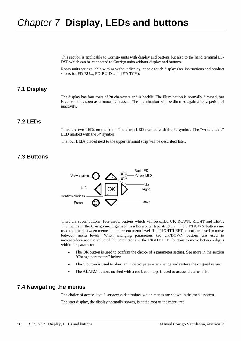
56 Chapter 7 Display, LEDs and buttons Manual Corrigo Ventilation, revision V
Chapter 7 Display, LEDs and buttons
This section is applicable to Corrigo units with display and buttons but also to the hand terminal E3-DSP which can be connected to Corrigo units without display and buttons.
Room units are available with or without display, or as a touch display (see instructions and product sheets for ED-RU..., ED-RU-D... and ED-TCV).
7.1 Display The display has four rows of 20 characters and is backlit. The illumination is normally dimmed, but is activated as soon as a button is pressed. The illumination will be dimmed again after a period of inactivity.
7.2 LEDs There are two LEDs on the front: The alarm LED marked with the symbol. The “write enable” LED marked with the symbol.
The four LEDs placed next to the upper terminal strip will be described later.
7.3 Buttons
There are seven buttons: four arrow buttons which will be called UP, DOWN, RIGHT and LEFT. The menus in the Corrigo are organized in a horizontal tree structure. The UP/DOWN buttons are used to move between menus at the present menu level. The RIGHT/LEFT buttons are used to move between menu levels. When changing parameters the UP/DOWN buttons are used to increase/decrease the value of the parameter and the RIGHT/LEFT buttons to move between digits within the parameter.
• The OK button is used to confirm the choice of a parameter setting. See more in the section "Change parameters" below.
• The C button is used to abort an initiated parameter change and restore the original value.
• The ALARM button, marked with a red button top, is used to access the alarm list.
7.4 Navigating the menus The choice of access level/user access determines which menus are shown in the menu system.
The start display, the display normally shown, is at the root of the menu tree.
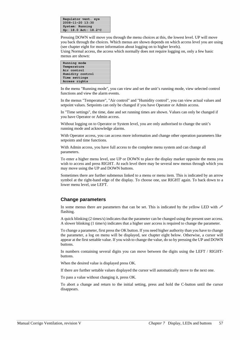
Manual Corrigo Ventilation, revision V Chapter 7 Display, LEDs and buttons 57
Regulator vent. sys 2008-11-20 13:30 System: Running Sp: 18.0 Act: 18.2°C
Pressing DOWN will move you through the menu choices at this, the lowest level. UP will move you back through the choices. Which menus are shown depends on which access level you are using (see chapter eight for more information about logging on to higher levels). Using Normal access, the access which normally does not require logging on, only a few basic menus are shown: Running mode Temperature Air control Humidity control Time settings Access rights
In the menu "Running mode", you can view and set the unit’s running mode, view selected control functions and view the alarm events.
In the menus "Temperature", "Air control" and "Humidity control", you can view actual values and setpoint values. Setpoints can only be changed if you have Operator or Admin access.
In "Time settings", the time, date and set running times are shown. Values can only be changed if you have Operator or Admin access.
Without logging on to Operator or System level, you are only authorised to change the unit’s running mode and acknowledge alarms.
With Operator access, you can access more information and change other operation parameters like setpoints and time functions.
With Admin access, you have full access to the complete menu system and can change all parameters.
To enter a higher menu level, use UP or DOWN to place the display marker opposite the menu you wish to access and press RIGHT. At each level there may be several new menus through which you may move using the UP and DOWN buttons.
Sometimes there are further submenus linked to a menu or menu item. This is indicated by an arrow symbol at the right-hand edge of the display. To choose one, use RIGHT again. To back down to a lower menu level, use LEFT.
Change parameters In some menus there are parameters that can be set. This is indicated by the yellow LED with flashing.
A quick blinking (2 times/s) indicates that the parameter can be changed using the present user access. A slower blinking (1 time/s) indicates that a higher user access is required to change the parameter.
To change a parameter, first press the OK button. If you need higher authority than you have to change the parameter, a log on menu will be displayed, see chapter eight below. Otherwise, a cursor will appear at the first settable value. If you wish to change the value, do so by pressing the UP and DOWN buttons.
In numbers containing several digits you can move between the digits using the LEFT / RIGHT-buttons.
When the desired value is displayed press OK.
If there are further settable values displayed the cursor will automatically move to the next one.
To pass a value without changing it, press OK.
To abort a change and return to the initial setting, press and hold the C-button until the cursor disappears.
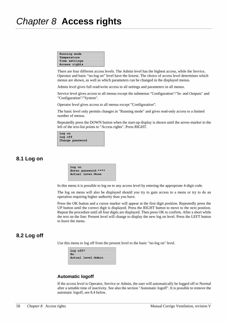
58 Chapter 8 Access rights Manual Corrigo Ventilation, revision V
Chapter 8 Access rights
Running mode Temperature Time settings Access rights
There are four different access levels. The Admin level has the highest access, while the Service, Operator and basic “no-log on” level have the lowest. The choice of access level determines which menus are shown, as well as which parameters can be changed in the displayed menus.
Admin level gives full read/write access to all settings and parameters in all menus.
Service level gives access to all menus except the submenus "Configuration"/"In- and Outputs" and "Configuration"/"System".
Operator level gives access to all menus except ”Configuration”.
The basic level only permits changes in "Running mode" and gives read-only access to a limited number of menus.
Repeatedly press the DOWN button when the start-up display is shown until the arrow-marker to the left of the text-list points to "Access rights". Press RIGHT. Log on Log off Change password
8.1 Log on Log on Enter password:**** Actual level:None
In this menu it is possible to log on to any access level by entering the appropriate 4-digit code.
The log on menu will also be displayed should you try to gain access to a menu or try to do an operation requiring higher authority than you have.
Press the OK button and a cursor marker will appear at the first digit position. Repeatedly press the UP button until the correct digit is displayed. Press the RIGHT button to move to the next position. Repeat the procedure until all four digits are displayed. Then press OK to confirm. After a short while the text on the line: Present level will change to display the new log on level. Press the LEFT button to leave the menu.
8.2 Log off Use this menu to log off from the present level to the basic "no-log on" level.
Log off? No Actual level:Admin
Automatic logoff If the access level is Operator, Service or Admin, the user will automatically be logged off to Normal after a settable time of inactivity. See also the section "Automatic logoff". It is possible to remove the automatic logoff, see 8.4 below.
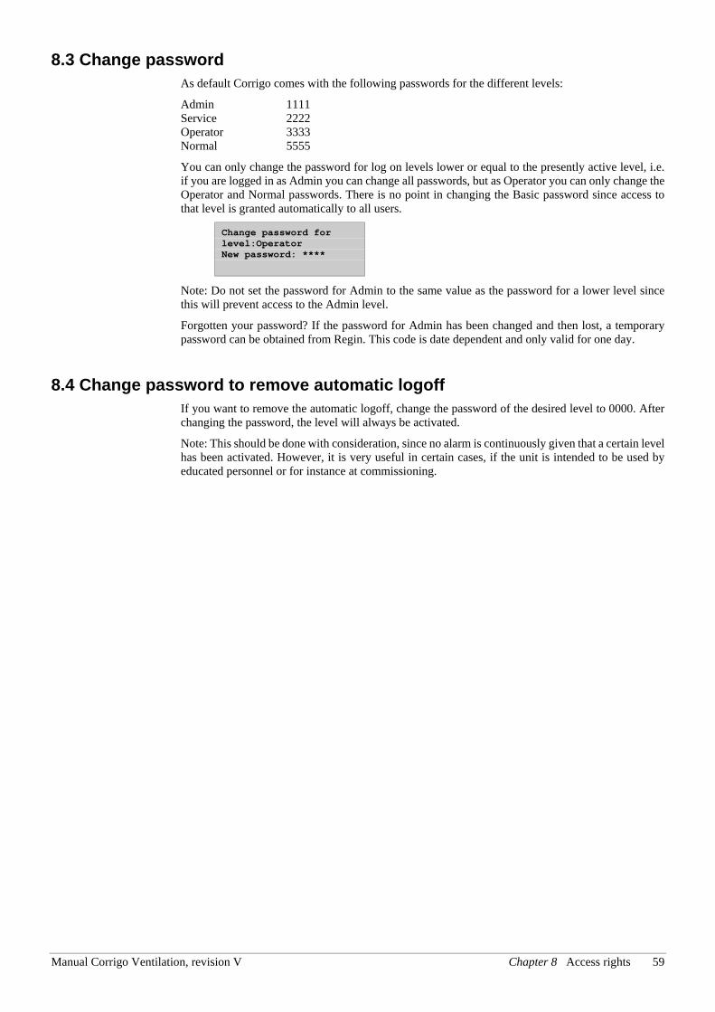
Manual Corrigo Ventilation, revision V Chapter 8 Access rights 59
8.3 Change password As default Corrigo comes with the following passwords for the different levels:
Admin 1111 Service 2222 Operator 3333 Normal 5555
You can only change the password for log on levels lower or equal to the presently active level, i.e. if you are logged in as Admin you can change all passwords, but as Operator you can only change the Operator and Normal passwords. There is no point in changing the Basic password since access to that level is granted automatically to all users.
Change password for level:Operator New password: ****
Note: Do not set the password for Admin to the same value as the password for a lower level since this will prevent access to the Admin level.
Forgotten your password? If the password for Admin has been changed and then lost, a temporary password can be obtained from Regin. This code is date dependent and only valid for one day.
8.4 Change password to remove automatic logoff If you want to remove the automatic logoff, change the password of the desired level to 0000. After changing the password, the level will always be activated.
Note: This should be done with consideration, since no alarm is continuously given that a certain level has been activated. However, it is very useful in certain cases, if the unit is intended to be used by educated personnel or for instance at commissioning.
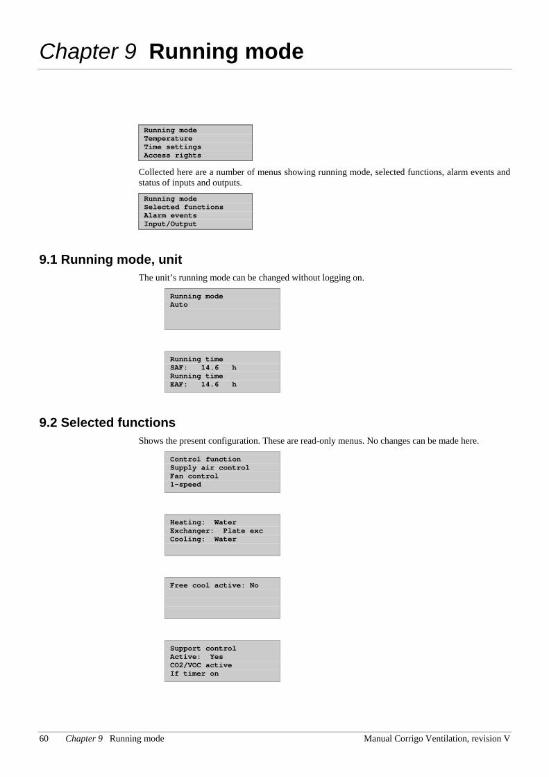
60 Chapter 9 Running mode Manual Corrigo Ventilation, revision V
Chapter 9 Running mode
Running mode Temperature Time settings Access rights
Collected here are a number of menus showing running mode, selected functions, alarm events and status of inputs and outputs. Running mode Selected functions Alarm events Input/Output
9.1 Running mode, unit The unit’s running mode can be changed without logging on.
Running mode Auto
Running time SAF: 14.6 h Running time EAF: 14.6 h
9.2 Selected functions Shows the present configuration. These are read-only menus. No changes can be made here.
Control function Supply air control Fan control 1-speed
Heating: Water Exchanger: Plate exc Cooling: Water
Free cool active: No
Support control Active: Yes CO2/VOC active If timer on
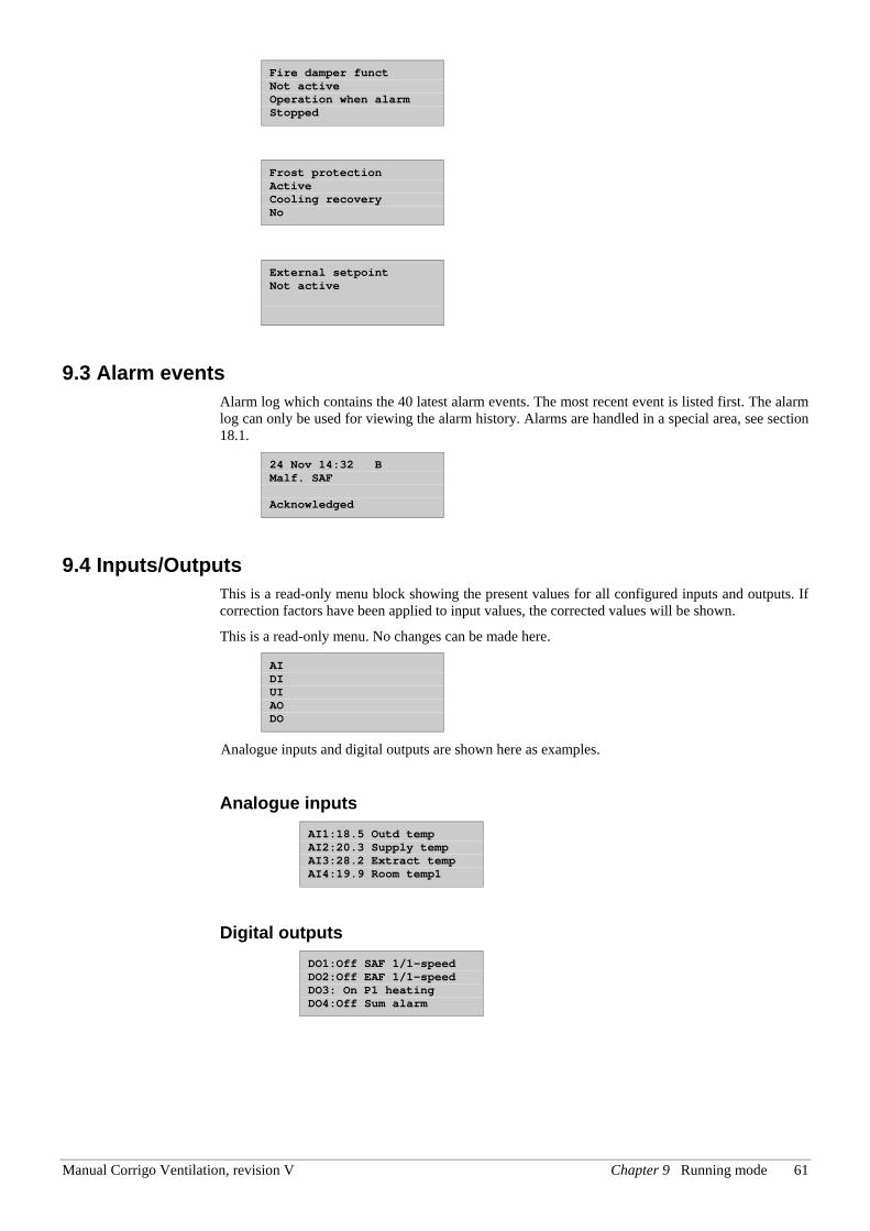
Manual Corrigo Ventilation, revision V Chapter 9 Running mode 61
Fire damper funct Not active Operation when alarm Stopped
Frost protection Active Cooling recovery No
External setpoint Not active
9.3 Alarm events Alarm log which contains the 40 latest alarm events. The most recent event is listed first. The alarm log can only be used for viewing the alarm history. Alarms are handled in a special area, see section 18.1.
24 Nov 14:32 B Malf. SAF Acknowledged
9.4 Inputs/Outputs This is a read-only menu block showing the present values for all configured inputs and outputs. If correction factors have been applied to input values, the corrected values will be shown.
This is a read-only menu. No changes can be made here.
AI DI UI AO DO
Analogue inputs and digital outputs are shown here as examples.
Analogue inputs AI1:18.5 Outd temp AI2:20.3 Supply temp AI3:28.2 Extract temp AI4:19.9 Room temp1
Digital outputs DO1:Off SAF 1/1-speed DO2:Off EAF 1/1-speed DO3: On P1 heating DO4:Off Sum alarm
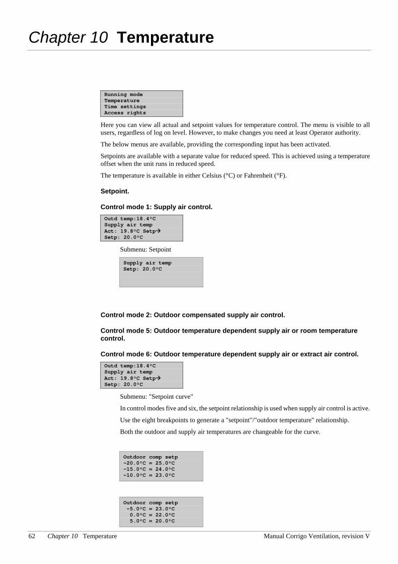
62 Chapter 10 Temperature Manual Corrigo Ventilation, revision V
Chapter 10 Temperature
Running mode Temperature Time settings Access rights
Here you can view all actual and setpoint values for temperature control. The menu is visible to all users, regardless of log on level. However, to make changes you need at least Operator authority.
The below menus are available, providing the corresponding input has been activated.
Setpoints are available with a separate value for reduced speed. This is achieved using a temperature offset when the unit runs in reduced speed.
The temperature is available in either Celsius (°C) or Fahrenheit (°F).
Setpoint.
Control mode 1: Supply air control. Outd temp:18.4°C Supply air temp Act: 19.8°C Setp Setp: 20.0°C
Submenu: Setpoint
Supply air temp Setp: 20.0°C
Control mode 2: Outdoor compensated supply air control.
Control mode 5: Outdoor temperature dependent supply air or room temperature control.
Control mode 6: Outdoor temperature dependent supply air or extract air control. Outd temp:18.4°C Supply air temp Act: 19.8°C Setp Setp: 20.0°C
Submenu: "Setpoint curve"
In control modes five and six, the setpoint relationship is used when supply air control is active.
Use the eight breakpoints to generate a "setpoint"/"outdoor temperature" relationship.
Both the outdoor and supply air temperatures are changeable for the curve.
Outdoor comp setp -20.0°C = 25.0°C -15.0°C = 24.0°C -10.0°C = 23.0°C
Outdoor comp setp -5.0°C = 23.0°C 0.0°C = 22.0°C 5.0°C = 20.0°C
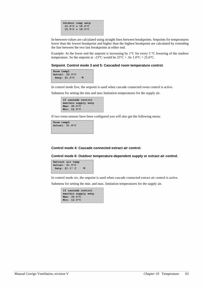
Manual Corrigo Ventilation, revision V Chapter 10 Temperature 63
Outdoor comp setp 10.0°C = 18.0°C 15.0°C = 18.0°C
In-between-values are calculated using straight lines between breakpoints. Setpoints for temperatures lower than the lowest breakpoint and higher than the highest breakpoint are calculated by extending the line between the two last breakpoints at either end.
Example: At the lower end the setpoint is increasing by 1°C for every 5 °C lowering of the outdoor temperature. So the setpoint at –23°C would be 25°C + .6x 1.0°C = 25.6°C.
Setpoint. Control mode 3 and 5: Cascaded room temperature control. Room temp1 Actual: 22.0°C Setp: 21.5°C
In control mode five, the setpoint is used when cascade connected room control is active.
Submenu for setting the min and max limitation temperatures for the supply air.
If cascade control max/min supply setp Max: 30.0°C Min: 12.0°C
If two room sensors have been configured you will also get the following menu: Room temp2 Actual: 21.8°C
Control mode 4: Cascade connected extract air control.
Control mode 6: Outdoor temperature-dependent supply or extract air control. Extract air temp Actual: 21.0°C Setp: 21.1° C
In control mode six, the setpoint is used when cascade connected extract air control is active.
Submenu for setting the min. and max. limitation temperatures for the supply air.
If cascade control max/min supply setp Max: 30.0°C Min: 12.0°C
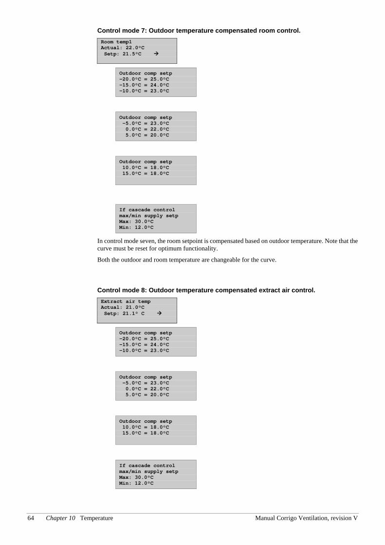
64 Chapter 10 Temperature Manual Corrigo Ventilation, revision V
Control mode 7: Outdoor temperature compensated room control. Room temp1 Actual: 22.0°C Setp: 21.5°C
Outdoor comp setp -20.0°C = 25.0°C -15.0°C = 24.0°C -10.0°C = 23.0°C
Outdoor comp setp -5.0°C = 23.0°C 0.0°C = 22.0°C 5.0°C = 20.0°C
Outdoor comp setp 10.0°C = 18.0°C 15.0°C = 18.0°C
If cascade control max/min supply setp Max: 30.0°C Min: 12.0°C
In control mode seven, the room setpoint is compensated based on outdoor temperature. Note that the curve must be reset for optimum functionality.
Both the outdoor and room temperature are changeable for the curve.
Control mode 8: Outdoor temperature compensated extract air control. Extract air temp Actual: 21.0°C Setp: 21.1° C
Outdoor comp setp -20.0°C = 25.0°C -15.0°C = 24.0°C -10.0°C = 23.0°C
Outdoor comp setp -5.0°C = 23.0°C 0.0°C = 22.0°C 5.0°C = 20.0°C
Outdoor comp setp 10.0°C = 18.0°C 15.0°C = 18.0°C
If cascade control max/min supply setp Max: 30.0°C Min: 12.0°C
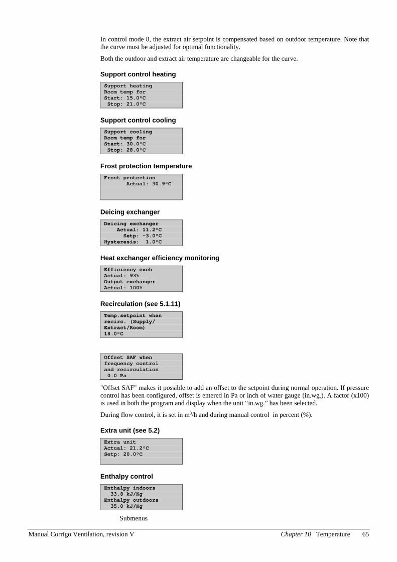
Manual Corrigo Ventilation, revision V Chapter 10 Temperature 65
In control mode 8, the extract air setpoint is compensated based on outdoor temperature. Note that the curve must be adjusted for optimal functionality.
Both the outdoor and extract air temperature are changeable for the curve.
Support control heating Support heating Room temp for Start: 15.0°C Stop: 21.0°C
Support control cooling Support cooling Room temp for Start: 30.0°C Stop: 28.0°C
Frost protection temperature Frost protection Actual: 30.9°C
Deicing exchanger Deicing exchanger Actual: 11.2°C Setp: -3.0°C Hysteresis: 1.0°C
Heat exchanger efficiency monitoring Efficiency exch Actual: 93% Output exchanger Actual: 100%
Recirculation (see 5.1.11) Temp.setpoint when recirc. (Supply/ Extract/Room) 18.0°C
Offset SAF when frequency control and recirculation 0.0 Pa
"Offset SAF" makes it possible to add an offset to the setpoint during normal operation. If pressure control has been configured, offset is entered in Pa or inch of water gauge (in.wg.). A factor (x100) is used in both the program and display when the unit “in.wg.” has been selected.
During flow control, it is set in m3/h and during manual control in percent (%).
Extra unit (see 5.2) Extra unit Actual: 21.2°C Setp: 20.0°C
Enthalpy control Enthalpy indoors 33.8 kJ/Kg Enthalpy outdoors 35.0 kJ/Kg
Submenus
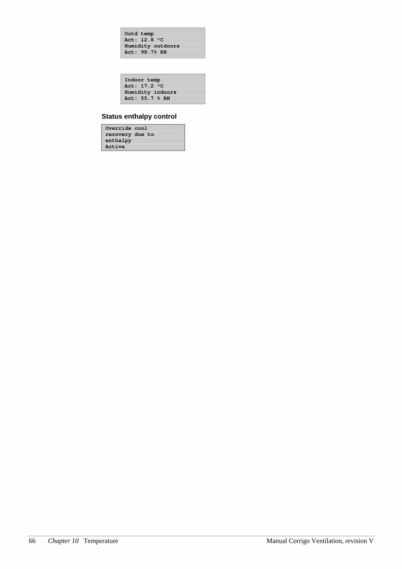
66 Chapter 10 Temperature Manual Corrigo Ventilation, revision V
Outd temp Act: 12.8 °C Humidity outdoors Act: 98.7% RH
Indoor temp Act: 17.2 °C Humidity indoors Act: 55.7 % RH
Status enthalpy control Override cool recovery due to enthalpy Active
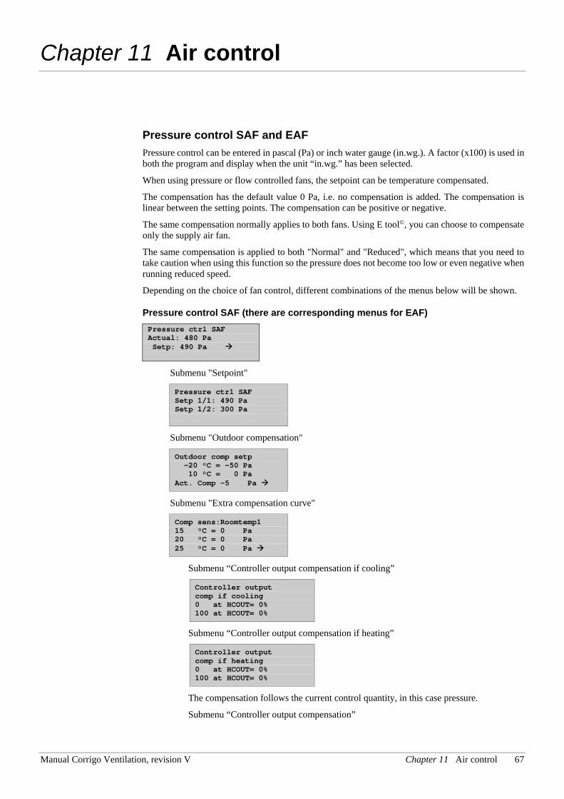
Manual Corrigo Ventilation, revision V Chapter 11 Air control 67
Chapter 11 Air control
Pressure control SAF and EAF Pressure control can be entered in pascal (Pa) or inch water gauge (in.wg.). A factor (x100) is used in both the program and display when the unit “in.wg.” has been selected.
When using pressure or flow controlled fans, the setpoint can be temperature compensated.
The compensation has the default value 0 Pa, i.e. no compensation is added. The compensation is linear between the setting points. The compensation can be positive or negative.
The same compensation normally applies to both fans. Using E tool©, you can choose to compensate only the supply air fan.
The same compensation is applied to both "Normal" and "Reduced", which means that you need to take caution when using this function so the pressure does not become too low or even negative when running reduced speed.
Depending on the choice of fan control, different combinations of the menus below will be shown.
Pressure control SAF (there are corresponding menus for EAF) Pressure ctrl SAF Actual: 480 Pa Setp: 490 Pa
Submenu "Setpoint"
Pressure ctrl SAF Setp 1/1: 490 Pa Setp 1/2: 300 Pa
Submenu "Outdoor compensation"
Outdoor comp setp -20 °C = -50 Pa 10 °C = 0 Pa Act. Comp -5 Pa
Submenu "Extra compensation curve"
Comp sens:Roomtemp1 15 °C = 0 Pa 20 °C = 0 Pa 25 °C = 0 Pa
Submenu “Controller output compensation if cooling”
Controller output comp if cooling 0 at HCOUT= 0% 100 at HCOUT= 0%
Submenu “Controller output compensation if heating”
Controller output comp if heating 0 at HCOUT= 0% 100 at HCOUT= 0%
The compensation follows the current control quantity, in this case pressure.
Submenu “Controller output compensation”
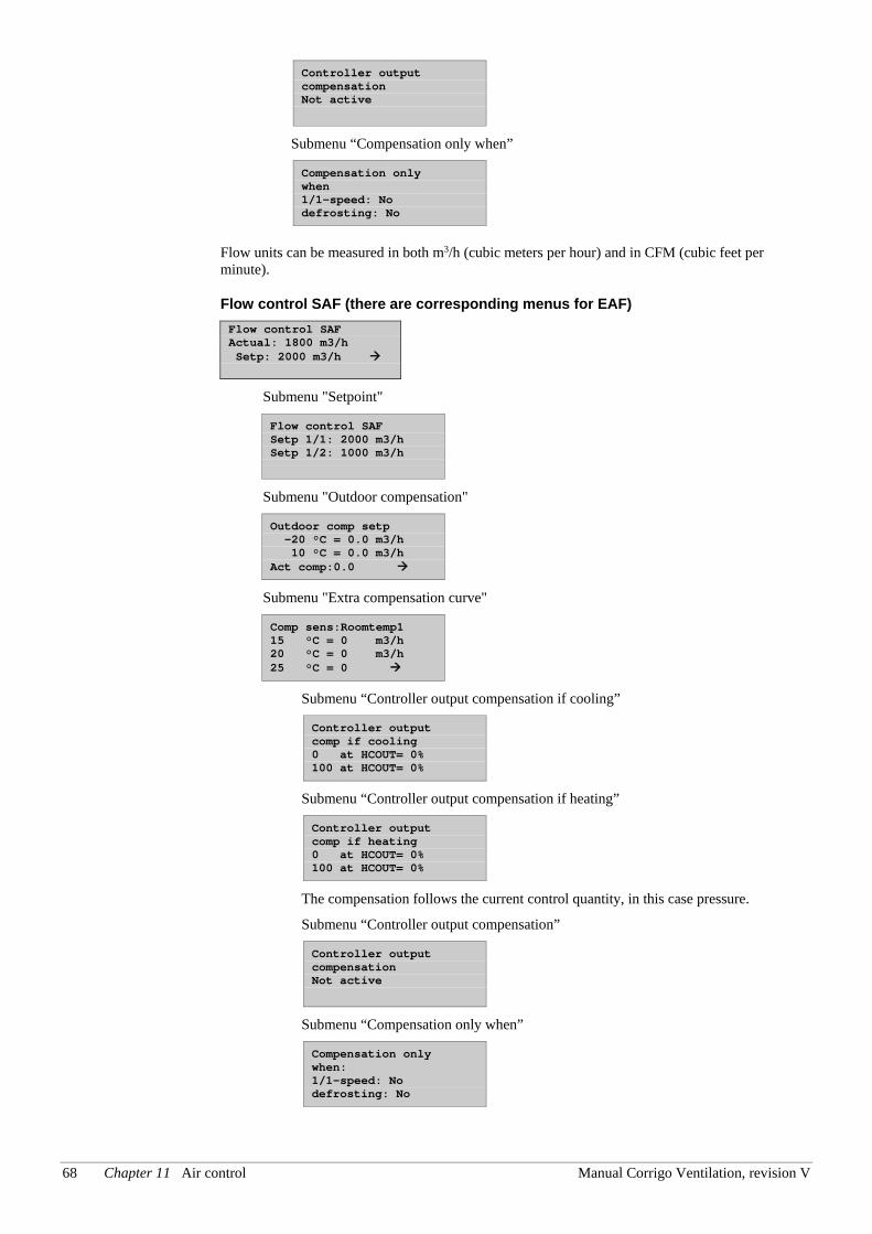
68 Chapter 11 Air control Manual Corrigo Ventilation, revision V
Controller output compensation Not active
Submenu “Compensation only when”
Compensation only when 1/1-speed: No defrosting: No
Flow units can be measured in both m3/h (cubic meters per hour) and in CFM (cubic feet per minute).
Flow control SAF (there are corresponding menus for EAF) Flow control SAF Actual: 1800 m3/h Setp: 2000 m3/h
Submenu "Setpoint"
Flow control SAF Setp 1/1: 2000 m3/h Setp 1/2: 1000 m3/h
Submenu "Outdoor compensation"
Outdoor comp setp -20 °C = 0.0 m3/h 10 °C = 0.0 m3/h Act comp:0.0
Submenu "Extra compensation curve"
Comp sens:Roomtemp1 15 °C = 0 m3/h 20 °C = 0 m3/h 25 °C = 0
Submenu “Controller output compensation if cooling”
Controller output comp if cooling 0 at HCOUT= 0% 100 at HCOUT= 0%
Submenu “Controller output compensation if heating”
Controller output comp if heating 0 at HCOUT= 0% 100 at HCOUT= 0%
The compensation follows the current control quantity, in this case pressure.
Submenu “Controller output compensation”
Controller output compensation Not active
Submenu “Compensation only when”
Compensation only when: 1/1-speed: No defrosting: No
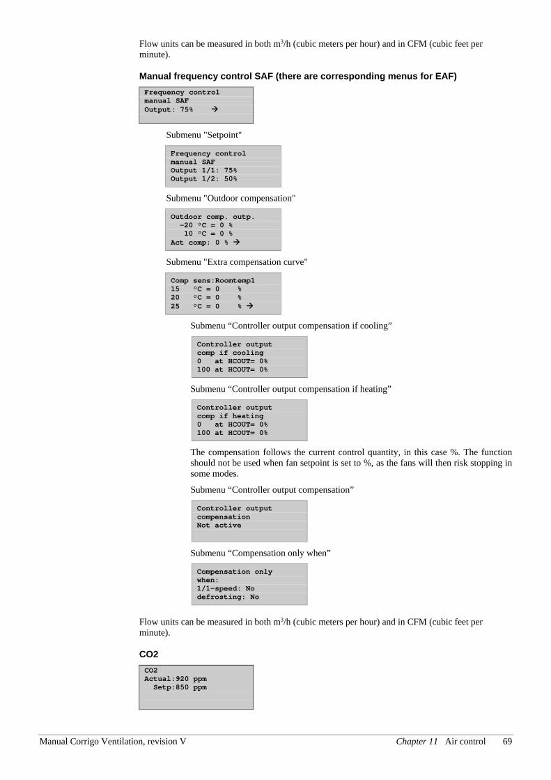
Manual Corrigo Ventilation, revision V Chapter 11 Air control 69
Flow units can be measured in both m3/h (cubic meters per hour) and in CFM (cubic feet per minute).
Manual frequency control SAF (there are corresponding menus for EAF) Frequency control manual SAF Output: 75%
Submenu "Setpoint"
Frequency control manual SAF Output 1/1: 75% Output 1/2: 50%
Submenu "Outdoor compensation"
Outdoor comp. outp. -20 °C = 0 % 10 °C = 0 % Act comp: 0 %
Submenu "Extra compensation curve"
Comp sens:Roomtemp1 15 °C = 0 % 20 °C = 0 % 25 °C = 0 %
Submenu “Controller output compensation if cooling”
Controller output comp if cooling 0 at HCOUT= 0% 100 at HCOUT= 0%
Submenu “Controller output compensation if heating”
Controller output comp if heating 0 at HCOUT= 0% 100 at HCOUT= 0%
The compensation follows the current control quantity, in this case %. The function should not be used when fan setpoint is set to %, as the fans will then risk stopping in some modes.
Submenu “Controller output compensation”
Controller output compensation Not active
Submenu “Compensation only when”
Compensation only when: 1/1-speed: No defrosting: No
Flow units can be measured in both m3/h (cubic meters per hour) and in CFM (cubic feet per minute).
CO2 CO2 Actual:920 ppm Setp:850 ppm
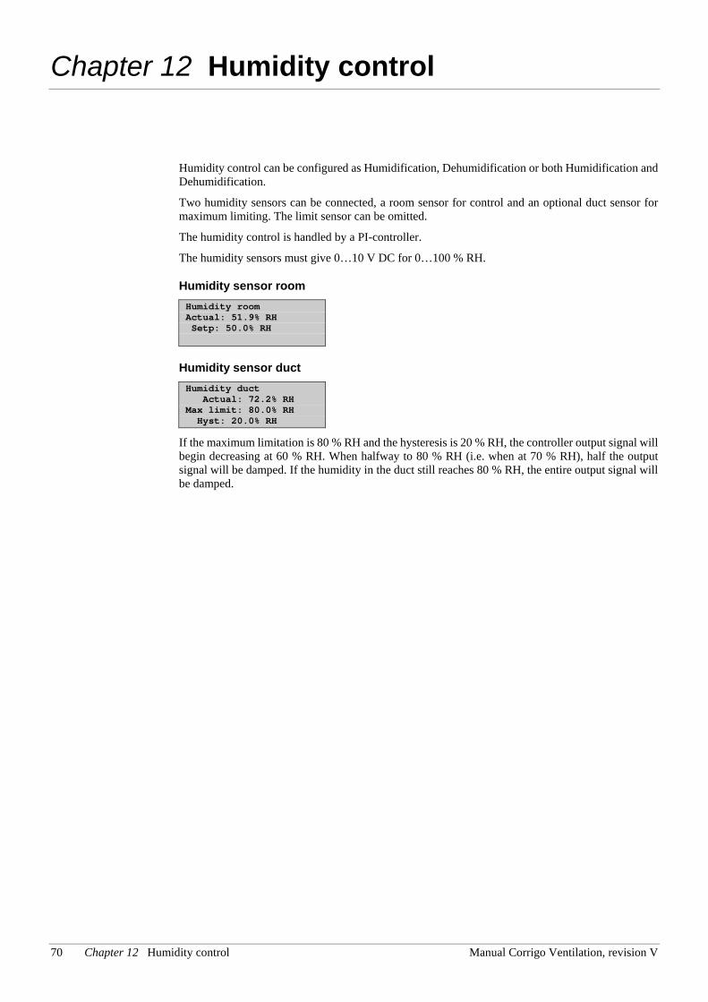
70 Chapter 12 Humidity control Manual Corrigo Ventilation, revision V
Chapter 12 Humidity control
Humidity control can be configured as Humidification, Dehumidification or both Humidification and Dehumidification.
Two humidity sensors can be connected, a room sensor for control and an optional duct sensor for maximum limiting. The limit sensor can be omitted.
The humidity control is handled by a PI-controller.
The humidity sensors must give 0…10 V DC for 0…100 % RH.
Humidity sensor room Humidity room Actual: 51.9% RH Setp: 50.0% RH
Humidity sensor duct Humidity duct Actual: 72.2% RH Max limit: 80.0% RH Hyst: 20.0% RH
If the maximum limitation is 80 % RH and the hysteresis is 20 % RH, the controller output signal will begin decreasing at 60 % RH. When halfway to 80 % RH (i.e. when at 70 % RH), half the output signal will be damped. If the humidity in the duct still reaches 80 % RH, the entire output signal will be damped.
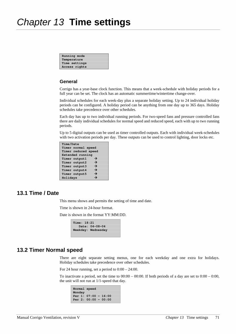
Manual Corrigo Ventilation, revision V Chapter 13 Time settings 71
Chapter 13 Time settings
Running mode Temperature Time settings Access rights
General Corrigo has a year-base clock function. This means that a week-schedule with holiday periods for a full year can be set. The clock has an automatic summertime/wintertime change-over.
Individual schedules for each week-day plus a separate holiday setting. Up to 24 individual holiday periods can be configured. A holiday period can be anything from one day up to 365 days. Holiday schedules take precedence over other schedules.
Each day has up to two individual running periods. For two-speed fans and pressure controlled fans there are daily individual schedules for normal speed and reduced speed, each with up to two running periods.
Up to 5 digital outputs can be used as timer controlled outputs. Each with individual week-schedules with two activation periods per day. These outputs can be used to control lighting, door locks etc. Time/Date Timer normal speed Timer reduced speed Extended running Timer output1 Timer output2 Timer output3 Timer output4 Timer output5 Holidays
13.1 Time / Date This menu shows and permits the setting of time and date.
Time is shown in 24-hour format.
Date is shown in the format YY:MM:DD.
Time: 18:21 Date: 04-08-04 Weekday: Wednesday
13.2 Timer Normal speed There are eight separate setting menus, one for each weekday and one extra for holidays. Holiday schedules take precedence over other schedules.
For 24 hour running, set a period to 0:00 – 24:00.
To inactivate a period, set the time to 00:00 – 00:00. If both periods of a day are set to 0:00 – 0:00, the unit will not run at 1/1-speed that day.
Normal speed Monday Per 1: 07:00 – 16:00 Per 2: 00:00 - 00:00
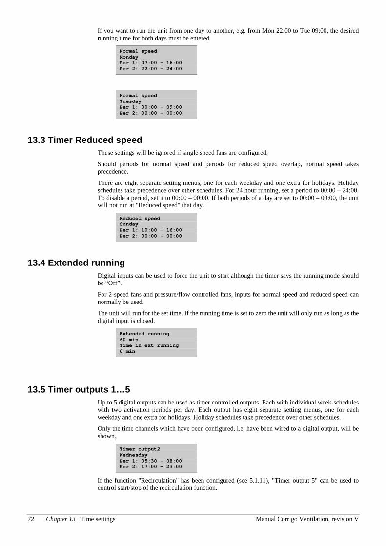
72 Chapter 13 Time settings Manual Corrigo Ventilation, revision V
If you want to run the unit from one day to another, e.g. from Mon 22:00 to Tue 09:00, the desired running time for both days must be entered.
Normal speed Monday Per 1: 07:00 – 16:00 Per 2: 22:00 - 24:00
Normal speed Tuesday Per 1: 00:00 – 09:00 Per 2: 00:00 - 00:00
13.3 Timer Reduced speed These settings will be ignored if single speed fans are configured.
Should periods for normal speed and periods for reduced speed overlap, normal speed takes precedence.
There are eight separate setting menus, one for each weekday and one extra for holidays. Holiday schedules take precedence over other schedules. For 24 hour running, set a period to 00:00 – 24:00. To disable a period, set it to 00:00 – 00:00. If both periods of a day are set to 00:00 – 00:00, the unit will not run at "Reduced speed" that day.
Reduced speed Sunday Per 1: 10:00 – 16:00 Per 2: 00:00 - 00:00
13.4 Extended running Digital inputs can be used to force the unit to start although the timer says the running mode should be “Off”.
For 2-speed fans and pressure/flow controlled fans, inputs for normal speed and reduced speed can normally be used.
The unit will run for the set time. If the running time is set to zero the unit will only run as long as the digital input is closed.
Extended running 60 min Time in ext running 0 min
13.5 Timer outputs 1…5 Up to 5 digital outputs can be used as timer controlled outputs. Each with individual week-schedules with two activation periods per day. Each output has eight separate setting menus, one for each weekday and one extra for holidays. Holiday schedules take precedence over other schedules.
Only the time channels which have been configured, i.e. have been wired to a digital output, will be shown.
Timer output2 Wednesday Per 1: 05:30 – 08:00 Per 2: 17:00 – 23:00
If the function "Recirculation" has been configured (see 5.1.11), "Timer output 5" can be used to control start/stop of the recirculation function.
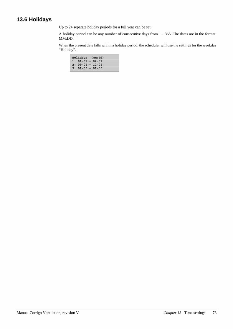
Manual Corrigo Ventilation, revision V Chapter 13 Time settings 73
13.6 Holidays Up to 24 separate holiday periods for a full year can be set.
A holiday period can be any number of consecutive days from 1…365. The dates are in the format: MM:DD.
When the present date falls within a holiday period, the scheduler will use the settings for the weekday “Holiday”.
Holidays (mm:dd) 1: 01-01 – 02-01 2: 09-04 – 12-04 3: 01-05 – 01-05
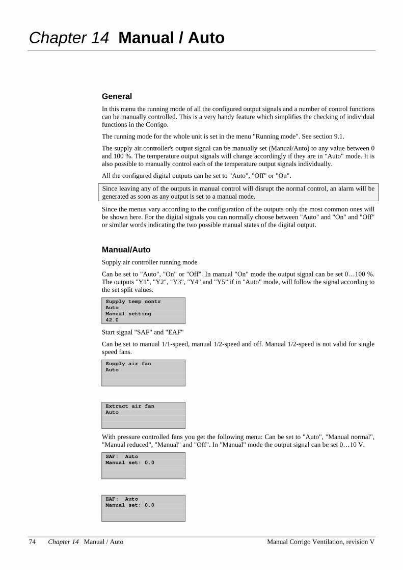
74 Chapter 14 Manual / Auto Manual Corrigo Ventilation, revision V
Chapter 14 Manual / Auto
General In this menu the running mode of all the configured output signals and a number of control functions can be manually controlled. This is a very handy feature which simplifies the checking of individual functions in the Corrigo.
The running mode for the whole unit is set in the menu "Running mode". See section 9.1.
The supply air controller's output signal can be manually set (Manual/Auto) to any value between 0 and 100 %. The temperature output signals will change accordingly if they are in "Auto" mode. It is also possible to manually control each of the temperature output signals individually.
All the configured digital outputs can be set to "Auto", "Off" or "On".
Since leaving any of the outputs in manual control will disrupt the normal control, an alarm will be generated as soon as any output is set to a manual mode.
Since the menus vary according to the configuration of the outputs only the most common ones will be shown here. For the digital signals you can normally choose between "Auto" and "On" and "Off" or similar words indicating the two possible manual states of the digital output.
Manual/Auto Supply air controller running mode
Can be set to "Auto", "On" or "Off". In manual "On" mode the output signal can be set 0…100 %. The outputs "Y1", "Y2", "Y3", "Y4" and "Y5” if in "Auto" mode, will follow the signal according to the set split values. Supply temp contr Auto Manual setting 42.0
Start signal "SAF" and "EAF"
Can be set to manual 1/1-speed, manual 1/2-speed and off. Manual 1/2-speed is not valid for single speed fans. Supply air fan Auto
Extract air fan Auto
With pressure controlled fans you get the following menu: Can be set to "Auto", "Manual normal", "Manual reduced", "Manual" and "Off". In "Manual" mode the output signal can be set 0…10 V. SAF: Auto Manual set: 0.0
EAF: Auto Manual set: 0.0
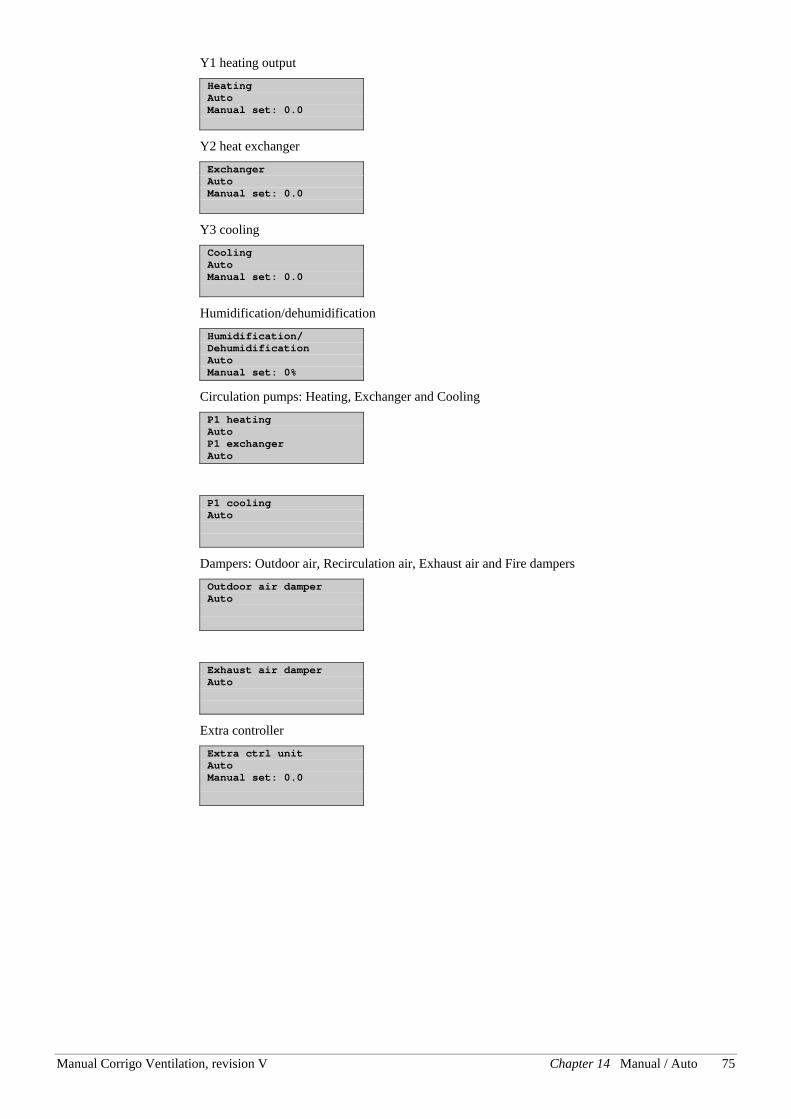
Manual Corrigo Ventilation, revision V Chapter 14 Manual / Auto 75
Y1 heating output Heating Auto Manual set: 0.0
Y2 heat exchanger Exchanger Auto Manual set: 0.0
Y3 cooling Cooling Auto Manual set: 0.0
Humidification/dehumidification Humidification/ Dehumidification Auto Manual set: 0%
Circulation pumps: Heating, Exchanger and Cooling P1 heating Auto P1 exchanger Auto
P1 cooling Auto
Dampers: Outdoor air, Recirculation air, Exhaust air and Fire dampers Outdoor air damper Auto
Exhaust air damper Auto
Extra controller Extra ctrl unit Auto Manual set: 0.0
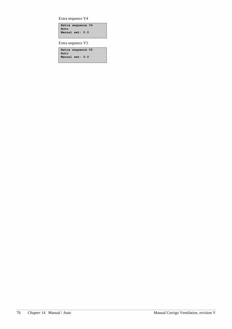
76 Chapter 14 Manual / Auto Manual Corrigo Ventilation, revision V
Extra sequence Y4 Extra sequence Y4 Auto Manual set: 0.0
Extra sequence Y5 Extra sequence Y5 Auto Manual set: 0.0
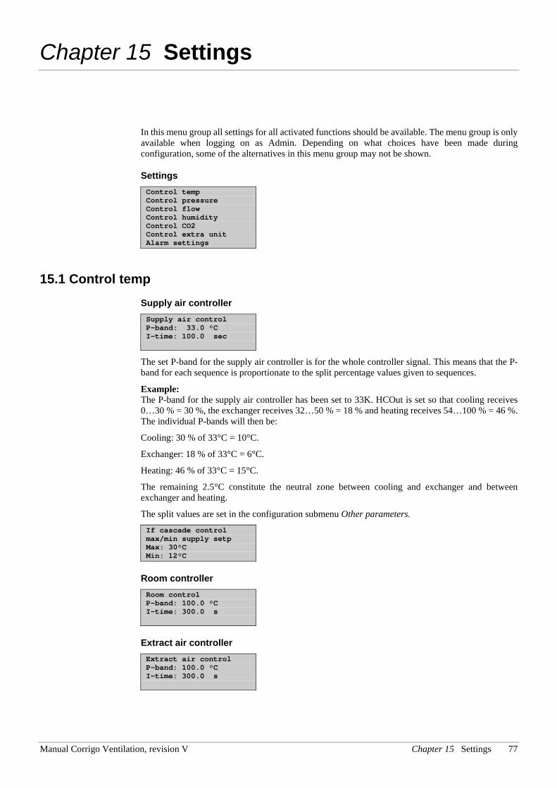
Manual Corrigo Ventilation, revision V Chapter 15 Settings 77
Chapter 15 Settings
In this menu group all settings for all activated functions should be available. The menu group is only available when logging on as Admin. Depending on what choices have been made during configuration, some of the alternatives in this menu group may not be shown.
Settings Control temp Control pressure Control flow Control humidity Control CO2 Control extra unit Alarm settings
15.1 Control temp Supply air controller Supply air control P-band: 33.0 °C I-time: 100.0 sec
The set P-band for the supply air controller is for the whole controller signal. This means that the P-band for each sequence is proportionate to the split percentage values given to sequences.
Example: The P-band for the supply air controller has been set to 33K. HCOut is set so that cooling receives 0…30 % = 30 %, the exchanger receives 32…50 % = 18 % and heating receives 54…100 % = 46 %. The individual P-bands will then be:
Cooling: 30 % of 33°C = 10°C.
Exchanger: 18 % of 33°C = 6°C.
Heating: 46 % of 33°C = 15°C.
The remaining 2.5°C constitute the neutral zone between cooling and exchanger and between exchanger and heating.
The split values are set in the configuration submenu Other parameters. If cascade control max/min supply setp Max: 30°C Min: 12°C
Room controller Room control P-band: 100.0 °C I-time: 300.0 s
Extract air controller Extract air control P-band: 100.0 °C I-time: 300.0 s
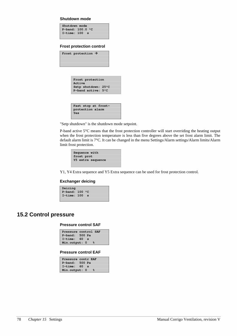
78 Chapter 15 Settings Manual Corrigo Ventilation, revision V
Shutdown mode Shutdown mode P-band: 100.0 °C I-time: 100 s
Frost protection control Frost protection
Frost protection Active Setp shutdown: 25°C P-band active: 5°C
Fast stop at frost-protection alarm Yes
"Setp shutdown" is the shutdown mode setpoint.
P-band active 5°C means that the frost protection controller will start overriding the heating output when the frost protection temperature is less than five degrees above the set frost alarm limit. The default alarm limit is 7°C. It can be changed in the menu Settings/Alarm settings/Alarm limits/Alarm limit frost protection.
Sequence with frost prot Y5 extra sequence
Y1, Y4 Extra sequence and Y5 Extra sequence can be used for frost protection control.
Exchanger deicing Deicing P-band: 100 °C I-time: 100 s
15.2 Control pressure Pressure control SAF Pressure control SAF P-band: 500 Pa I-time: 60 s Min.output: 0 %
Pressure control EAF Pressure contr EAF P-band: 500 Pa I-time: 60 s Min.output: 0 %
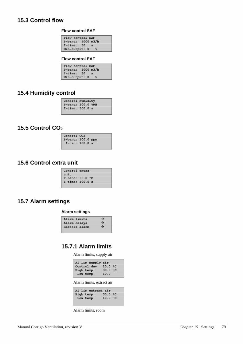
Manual Corrigo Ventilation, revision V Chapter 15 Settings 79
15.3 Control flow Flow control SAF Flow control SAF P-band: 1000 m3/h I-time: 60 s Min.output: 0 %
Flow control EAF Flow control EAF P-band: 1000 m3/h I-time: 60 s Min.output: 0 %
15.4 Humidity control Control humidity P-band: 100.0 %RH I-time: 300.0 s
15.5 Control CO2 Control CO2 P-band: 100.0 ppm I-tid: 100.0 s
15.6 Control extra unit Control extra unit P-band: 33.0 °C I-time: 100.0 s
15.7 Alarm settings Alarm settings Alarm limits Alarm delays Restore alarm
15.7.1 Alarm limits Alarm limits, supply air
Al lim supply air Control dev: 10.0 °C High temp: 30.0 °C Low temp: 10.0
Alarm limits, extract air
Al lim extract air High temp: 30.0 °C Low temp: 10.0 °C
Alarm limits, room
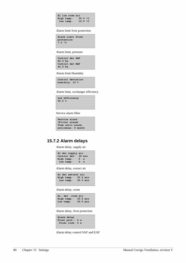
80 Chapter 15 Settings Manual Corrigo Ventilation, revision V
Al lim room air High temp: 30.0 °C Low temp: 10.0 °C
Alarm limit frost protection
Alarm limit frost protection 7.0 °C
Alarm limit, pressure
Control dev SAF 40.0 Pa Control dev EAF 40.0 Pa
Alarm limit Humidity
Control deviation humidity: 10 %
Alarm limit, exchanger efficiency
Low efficiency 50.0 %
Service alarm filter
Service alarm (Filter alarm) Time until alarm activates: 0 month
15.7.2 Alarm delays Alarm delay, supply air
Al del supply air Control dev: 30 min High temp: 5 s Low temp: 5 s
Alarm delay, extract air
Al del extract air High temp: 30.0 min Low temp: 30.0 min
Alarm delay, room
Al. del. room air High temp: 30.0 min Low temp: 30.0 min
Alarm delay, frost protection
Alarm delay Frost prot.: 0 s Frost risk: 0 s
Alarm delay control SAF and EAF
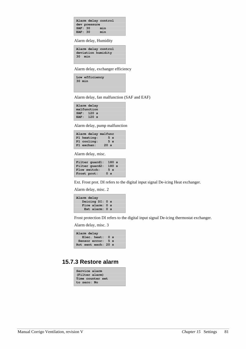
Manual Corrigo Ventilation, revision V Chapter 15 Settings 81
Alarm delay control dev pressure SAF: 30 min EAF: 30 min
Alarm delay, Humidity
Alarm delay control deviation humidity 30 min
Alarm delay, exchanger efficiency
Low efficiency 30 min
Alarm delay, fan malfunction (SAF and EAF)
Alarm delay malfunction SAF: 120 s EAF: 120 s
Alarm delay, pump malfunction
Alarm delay malfunc P1 heating: 5 s P1 cooling: 5 s P1 exchan: 20 s
Alarm delay, misc.
Filter guard1: 180 s Filter guard2: 180 s Flow switch: 5 s Frost prot: 0 s
Ext. Frost prot. DI refers to the digital input signal De-icing Heat exchanger.
Alarm delay, misc. 2
Alarm delay Deicing DI: 0 s Fire alarm: 0 s Ext alarm: 0 s
Frost protection DI refers to the digital input signal De-icing thermostat exchanger.
Alarm delay, misc. 3
Alarm delay Elec. heat: 0 s Sensor error: 5 s Rot sent exch: 20 s
15.7.3 Restore alarm Service alarm (Filter alarm) Time counter set to zero: No
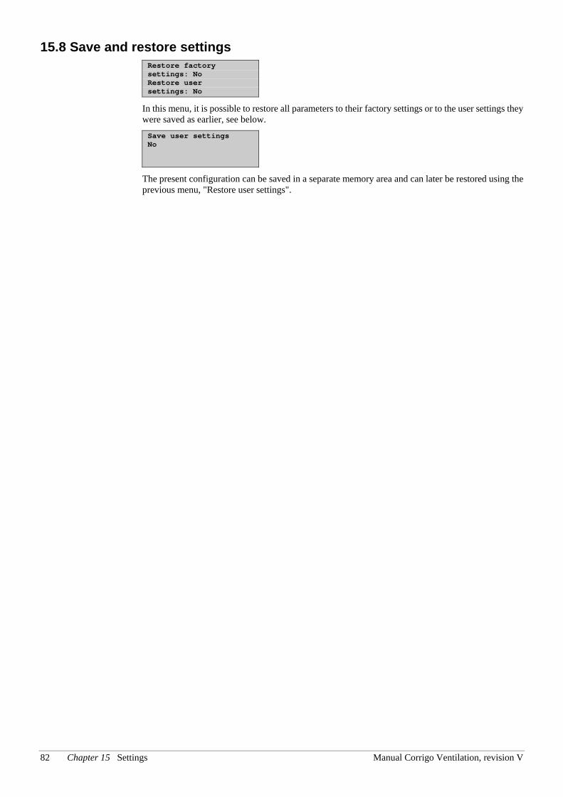
82 Chapter 15 Settings Manual Corrigo Ventilation, revision V
15.8 Save and restore settings Restore factory settings: No Restore user settings: No
In this menu, it is possible to restore all parameters to their factory settings or to the user settings they were saved as earlier, see below. Save user settings No
The present configuration can be saved in a separate memory area and can later be restored using the previous menu, "Restore user settings".
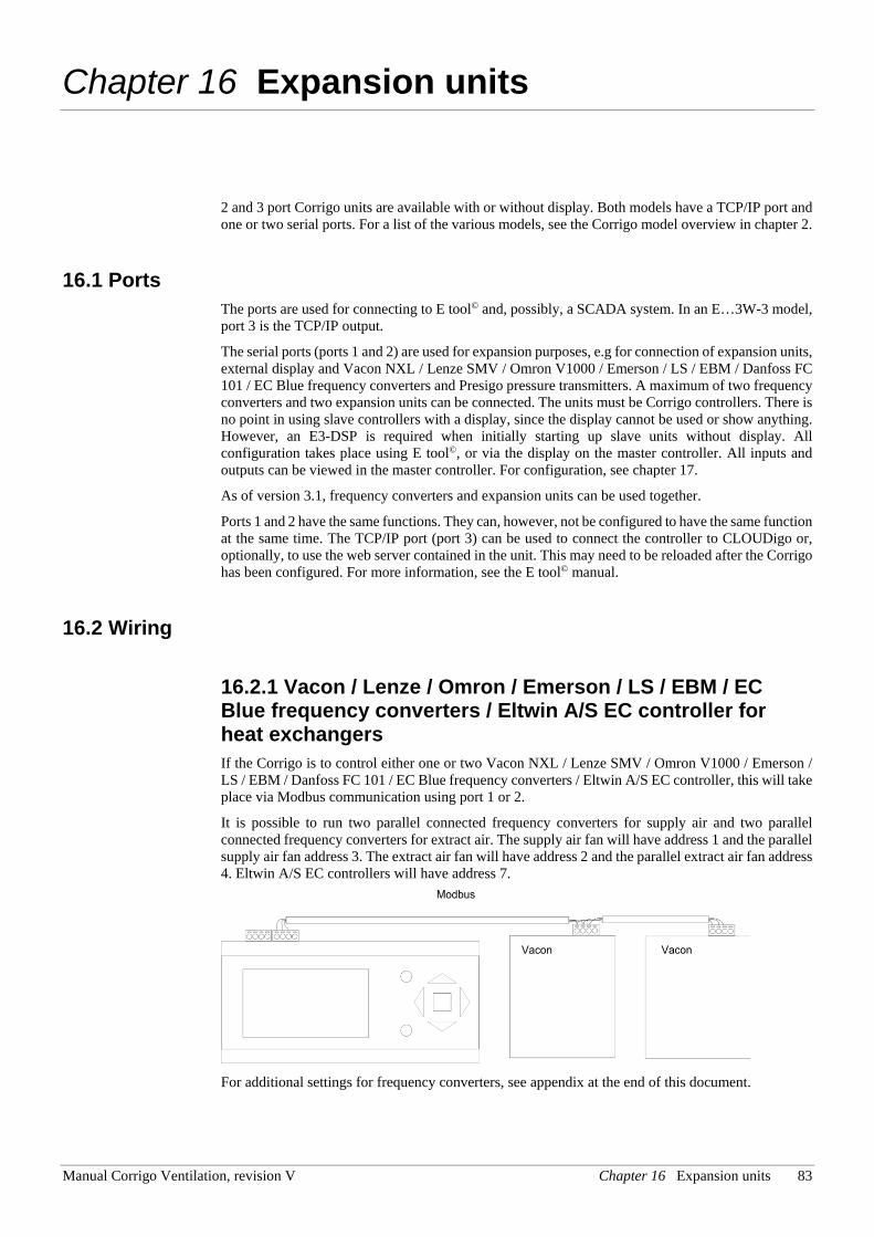
Manual Corrigo Ventilation, revision V Chapter 16 Expansion units 83
Chapter 16 Expansion units
2 and 3 port Corrigo units are available with or without display. Both models have a TCP/IP port and one or two serial ports. For a list of the various models, see the Corrigo model overview in chapter 2.
16.1 Ports The ports are used for connecting to E tool© and, possibly, a SCADA system. In an E…3W-3 model, port 3 is the TCP/IP output.
The serial ports (ports 1 and 2) are used for expansion purposes, e.g for connection of expansion units, external display and Vacon NXL / Lenze SMV / Omron V1000 / Emerson / LS / EBM / Danfoss FC 101 / EC Blue frequency converters and Presigo pressure transmitters. A maximum of two frequency converters and two expansion units can be connected. The units must be Corrigo controllers. There is no point in using slave controllers with a display, since the display cannot be used or show anything. However, an E3-DSP is required when initially starting up slave units without display. All configuration takes place using E tool©, or via the display on the master controller. All inputs and outputs can be viewed in the master controller. For configuration, see chapter 17.
As of version 3.1, frequency converters and expansion units can be used together.
Ports 1 and 2 have the same functions. They can, however, not be configured to have the same function at the same time. The TCP/IP port (port 3) can be used to connect the controller to CLOUDigo or, optionally, to use the web server contained in the unit. This may need to be reloaded after the Corrigo has been configured. For more information, see the E tool© manual.
16.2 Wiring
16.2.1 Vacon / Lenze / Omron / Emerson / LS / EBM / EC Blue frequency converters / Eltwin A/S EC controller for heat exchangers If the Corrigo is to control either one or two Vacon NXL / Lenze SMV / Omron V1000 / Emerson / LS / EBM / Danfoss FC 101 / EC Blue frequency converters / Eltwin A/S EC controller, this will take place via Modbus communication using port 1 or 2.
It is possible to run two parallel connected frequency converters for supply air and two parallel connected frequency converters for extract air. The supply air fan will have address 1 and the parallel supply air fan address 3. The extract air fan will have address 2 and the parallel extract air fan address 4. Eltwin A/S EC controllers will have address 7.
For additional settings for frequency converters, see appendix at the end of this document.
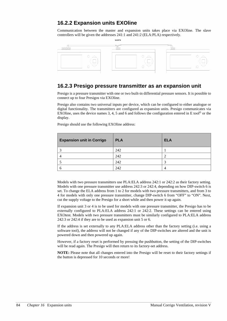
84 Chapter 16 Expansion units Manual Corrigo Ventilation, revision V
16.2.2 Expansion units EXOline Communication between the master and expansion units takes place via EXOline. The slave controllers will be given the addresses 241:1 and 241:2 (ELA:PLA) respectively.
16.2.3 Presigo pressure transmitter as an expansion unit Presigo is a pressure transmitter with one or two built-in differential pressure sensors. It is possible to connect up to four Presigos via EXOline.
Presigo also contains two universal inputs per device, which can be configured to either analogue or digital functionality. The transmitters are configured as expansion units. Presigo communicates via EXOline, uses the device names 3, 4, 5 and 6 and follows the configuration entered in E tool© or the display.
Presigo should use the following EXOline address:
Expansion unit in Corrigo PLA ELA
3 242 1 4 242 2 5 242 3 6 242 4
Models with two pressure transmitters use PLA:ELA address 242:1 or 242:2 as their factory setting. Models with one pressure transmitter use address 242:3 or 242:4, depending on how DIP-switch 6 is set. To change the ELA address from 1 to 2 for models with two pressure transmitters, and from 3 to 4 for models with only one pressure transmitter, change DIP-switch 6 from “OFF” to “ON”. Next, cut the supply voltage to the Presigo for a short while and then power it up again.
If expansion unit 3 or 4 is to be used for models with one pressure transmitter, the Presigo has to be externally configured to PLA:ELA address 242:1 or 242:2. These settings can be entered using EXOtest. Models with two pressure transmitters must be similarly configured to PLA:ELA address 242:3 or 242:4 if they are to be used as expansion unit 5 or 6.
If the address is set externally to any PLA:ELA address other than the factory setting (i.e. using a software tool), the address will not be changed if any of the DIP-switches are altered and the unit is powered down and then powered up again.
However, if a factory reset is performed by pressing the pushbutton, the setting of the DIP-switches will be read again. The Presigo will then return to its factory-set address.
NOTE: Please note that all changes entered into the Presigo will be reset to their factory settings if the button is depressed for 10 seconds or more!
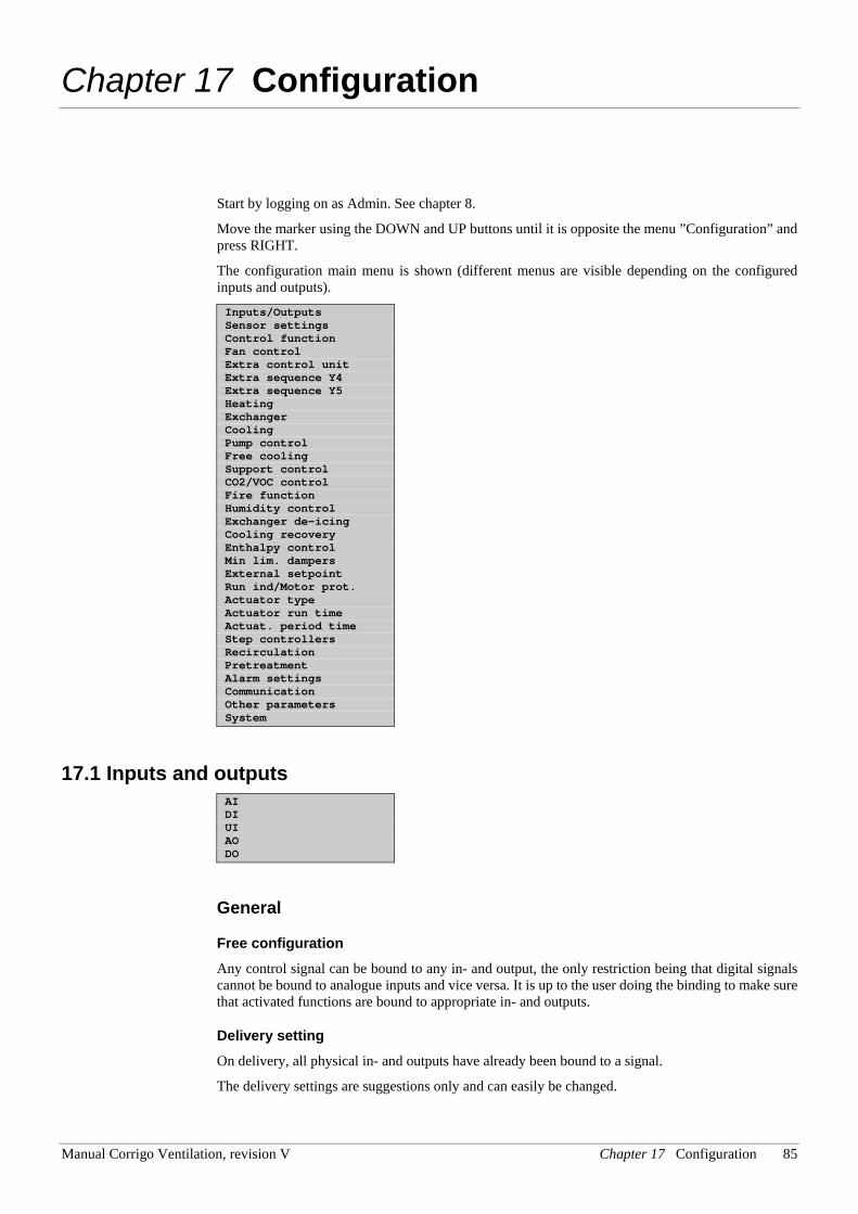
Manual Corrigo Ventilation, revision V Chapter 17 Configuration 85
Chapter 17 Configuration
Start by logging on as Admin. See chapter 8.
Move the marker using the DOWN and UP buttons until it is opposite the menu ”Configuration” and press RIGHT.
The configuration main menu is shown (different menus are visible depending on the configured inputs and outputs). Inputs/Outputs Sensor settings Control function Fan control Extra control unit Extra sequence Y4 Extra sequence Y5 Heating Exchanger Cooling Pump control Free cooling Support control CO2/VOC control Fire function Humidity control Exchanger de-icing Cooling recovery Enthalpy control Min lim. dampers External setpoint Run ind/Motor prot. Actuator type Actuator run time Actuat. period time Step controllers Recirculation Pretreatment Alarm settings Communication Other parameters System
17.1 Inputs and outputs AI DI UI AO DO
General
Free configuration Any control signal can be bound to any in- and output, the only restriction being that digital signals cannot be bound to analogue inputs and vice versa. It is up to the user doing the binding to make sure that activated functions are bound to appropriate in- and outputs.
Delivery setting On delivery, all physical in- and outputs have already been bound to a signal.
The delivery settings are suggestions only and can easily be changed.
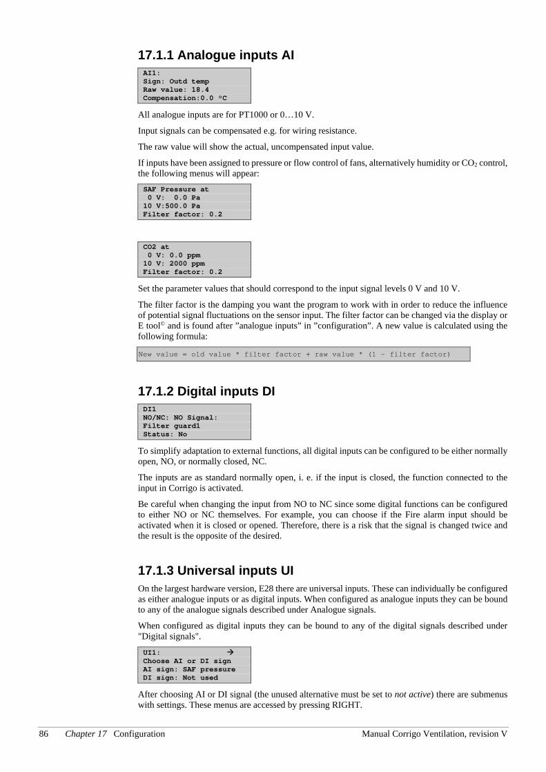
86 Chapter 17 Configuration Manual Corrigo Ventilation, revision V
17.1.1 Analogue inputs AI AI1: Sign: Outd temp Raw value: 18.4 Compensation:0.0 °C
All analogue inputs are for PT1000 or 0…10 V.
Input signals can be compensated e.g. for wiring resistance.
The raw value will show the actual, uncompensated input value.
If inputs have been assigned to pressure or flow control of fans, alternatively humidity or CO2 control, the following menus will appear: SAF Pressure at 0 V: 0.0 Pa 10 V:500.0 Pa Filter factor: 0.2
CO2 at 0 V: 0.0 ppm 10 V: 2000 ppm Filter factor: 0.2
Set the parameter values that should correspond to the input signal levels 0 V and 10 V.
The filter factor is the damping you want the program to work with in order to reduce the influence of potential signal fluctuations on the sensor input. The filter factor can be changed via the display or E tool© and is found after ”analogue inputs” in ”configuration”. A new value is calculated using the following formula:
New value = old value * filter factor + raw value * (1 - filter factor)
17.1.2 Digital inputs DI DI1 NO/NC: NO Signal: Filter guard1 Status: No
To simplify adaptation to external functions, all digital inputs can be configured to be either normally open, NO, or normally closed, NC.
The inputs are as standard normally open, i. e. if the input is closed, the function connected to the input in Corrigo is activated.
Be careful when changing the input from NO to NC since some digital functions can be configured to either NO or NC themselves. For example, you can choose if the Fire alarm input should be activated when it is closed or opened. Therefore, there is a risk that the signal is changed twice and the result is the opposite of the desired.
17.1.3 Universal inputs UI On the largest hardware version, E28 there are universal inputs. These can individually be configured as either analogue inputs or as digital inputs. When configured as analogue inputs they can be bound to any of the analogue signals described under Analogue signals.
When configured as digital inputs they can be bound to any of the digital signals described under "Digital signals".
UI1: Choose AI or DI sign AI sign: SAF pressure DI sign: Not used
After choosing AI or DI signal (the unused alternative must be set to not active) there are submenus with settings. These menus are accessed by pressing RIGHT.
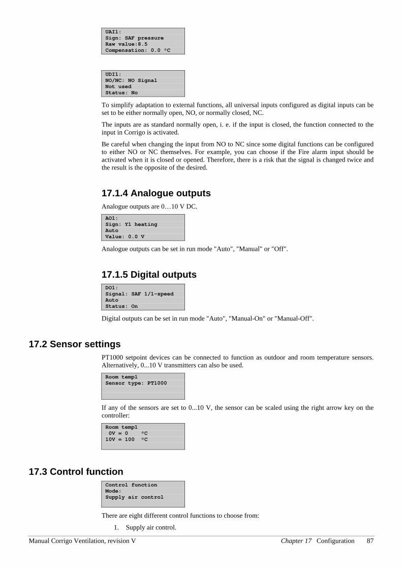
Manual Corrigo Ventilation, revision V Chapter 17 Configuration 87
UAI1: Sign: SAF pressure Raw value:8.5 Compensation: 0.0 °C
UDI1: NO/NC: NO Signal Not used Status: No
To simplify adaptation to external functions, all universal inputs configured as digital inputs can be set to be either normally open, NO, or normally closed, NC.
The inputs are as standard normally open, i. e. if the input is closed, the function connected to the input in Corrigo is activated.
Be careful when changing the input from NO to NC since some digital functions can be configured to either NO or NC themselves. For example, you can choose if the Fire alarm input should be activated when it is closed or opened. Therefore, there is a risk that the signal is changed twice and the result is the opposite of the desired.
17.1.4 Analogue outputs Analogue outputs are 0…10 V DC. AO1: Sign: Y1 heating Auto Value: 0.0 V
Analogue outputs can be set in run mode "Auto", "Manual" or "Off".
17.1.5 Digital outputs DO1: Signal: SAF 1/1-speed Auto Status: On
Digital outputs can be set in run mode "Auto", "Manual-On" or "Manual-Off".
17.2 Sensor settings PT1000 setpoint devices can be connected to function as outdoor and room temperature sensors. Alternatively, 0...10 V transmitters can also be used. Room temp1 Sensor type: PT1000
If any of the sensors are set to 0...10 V, the sensor can be scaled using the right arrow key on the controller: Room temp1 0V = 0 °C 10V = 100 °C
17.3 Control function Control function Mode: Supply air control
There are eight different control functions to choose from:
1. Supply air control.
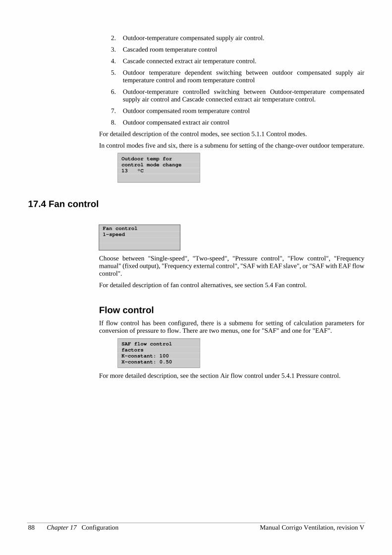
88 Chapter 17 Configuration Manual Corrigo Ventilation, revision V
2. Outdoor-temperature compensated supply air control.
3. Cascaded room temperature control
4. Cascade connected extract air temperature control.
5. Outdoor temperature dependent switching between outdoor compensated supply air temperature control and room temperature control
6. Outdoor-temperature controlled switching between Outdoor-temperature compensated supply air control and Cascade connected extract air temperature control.
7. Outdoor compensated room temperature control
8. Outdoor compensated extract air control
For detailed description of the control modes, see section 5.1.1 Control modes.
In control modes five and six, there is a submenu for setting of the change-over outdoor temperature.
Outdoor temp for control mode change 13 °C
17.4 Fan control Fan control 1-speed
Choose between "Single-speed", "Two-speed", "Pressure control", "Flow control", "Frequency manual" (fixed output), "Frequency external control", "SAF with EAF slave", or "SAF with EAF flow control".
For detailed description of fan control alternatives, see section 5.4 Fan control.
Flow control If flow control has been configured, there is a submenu for setting of calculation parameters for conversion of pressure to flow. There are two menus, one for "SAF" and one for "EAF".
SAF flow control factors K-constant: 100 X-constant: 0.50
For more detailed description, see the section Air flow control under 5.4.1 Pressure control.
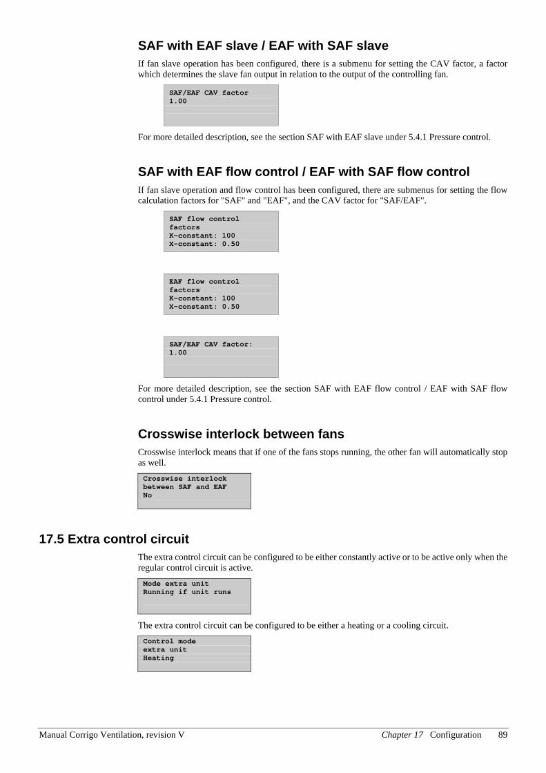
Manual Corrigo Ventilation, revision V Chapter 17 Configuration 89
SAF with EAF slave / EAF with SAF slave If fan slave operation has been configured, there is a submenu for setting the CAV factor, a factor which determines the slave fan output in relation to the output of the controlling fan.
SAF/EAF CAV factor 1.00
For more detailed description, see the section SAF with EAF slave under 5.4.1 Pressure control.
SAF with EAF flow control / EAF with SAF flow control If fan slave operation and flow control has been configured, there are submenus for setting the flow calculation factors for "SAF" and "EAF", and the CAV factor for "SAF/EAF".
SAF flow control factors K-constant: 100 X-constant: 0.50
EAF flow control factors K-constant: 100 X-constant: 0.50
SAF/EAF CAV factor: 1.00
For more detailed description, see the section SAF with EAF flow control / EAF with SAF flow control under 5.4.1 Pressure control.
Crosswise interlock between fans Crosswise interlock means that if one of the fans stops running, the other fan will automatically stop as well. Crosswise interlock between SAF and EAF No
17.5 Extra control circuit The extra control circuit can be configured to be either constantly active or to be active only when the regular control circuit is active. Mode extra unit Running if unit runs
The extra control circuit can be configured to be either a heating or a cooling circuit. Control mode extra unit Heating
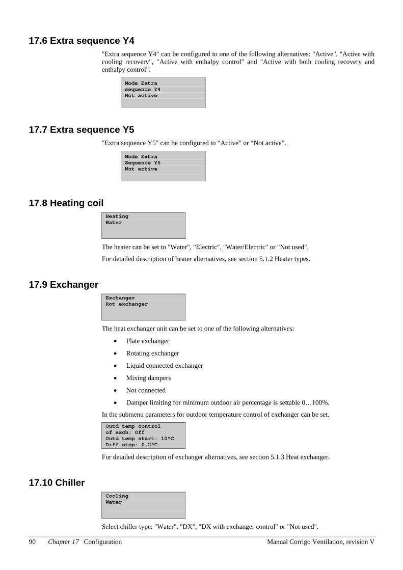
90 Chapter 17 Configuration Manual Corrigo Ventilation, revision V
17.6 Extra sequence Y4 "Extra sequence Y4" can be configured to one of the following alternatives: "Active", "Active with cooling recovery", "Active with enthalpy control" and "Active with both cooling recovery and enthalpy control".
Mode Extra sequence Y4 Not active
17.7 Extra sequence Y5 "Extra sequence Y5" can be configured to “Active” or “Not active”.
Mode Extra Sequence Y5 Not active
17.8 Heating coil Heating Water
The heater can be set to "Water", "Electric", "Water/Electric" or "Not used".
For detailed description of heater alternatives, see section 5.1.2 Heater types.
17.9 Exchanger Exchanger Rot exchanger
The heat exchanger unit can be set to one of the following alternatives:
• Plate exchanger
• Rotating exchanger
• Liquid connected exchanger
• Mixing dampers
• Not connected
• Damper limiting for minimum outdoor air percentage is settable 0…100%.
In the submenu parameters for outdoor temperature control of exchanger can be set. Outd temp control of exch: Off Outd temp start: 10°C Diff stop: 0.2°C
For detailed description of exchanger alternatives, see section 5.1.3 Heat exchanger.
17.10 Chiller Cooling Water
Select chiller type: "Water", "DX", "DX with exchanger control" or "Not used".
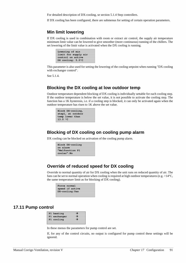
Manual Corrigo Ventilation, revision V Chapter 17 Configuration 91
For detailed description of DX-cooling, se section 5.1.4 Step controllers.
If DX cooling has been configured, there are submenus for setting of certain operation parameters.
Min limit lowering If DX cooling is used in combination with room or extract air control, the supply air temperature minimum limit value can be lowered to give smoother (more continuous) running of the chillers. The set lowering of the limit value is activated when the DX cooling is running.
Lowering of min limit for supply air control on active DX cooling: 5.0°C
This parameter is also used for setting the lowering of the cooling setpoint when running "DX cooling with exchanger control".
See 5.1.4.
Blocking the DX cooling at low outdoor temp Outdoor temperature dependent blocking of DX cooling is individually settable for each cooling step. If the outdoor temperature is below the set value, it is not possible to activate the cooling step. The function has a 1K hysteresis, i.e. if a cooling step is blocked, it can only be activated again when the outdoor temperature has risen to 1K above the set value.
Block DX-cooling, step1, at outdoor temp lower than 13.0 °C
Blocking of DX cooling on cooling pump alarm DX cooling can be blocked on activation of the cooling pump alarm.
Block DX-cooling on alarm ”Malfunction P1 cooler”:No
Override of reduced speed for DX cooling Override to normal quantity of air for DX cooling when the unit runs on reduced quantity of air. The fans can be set to normal operation when cooling is required at high outdoor temperatures (e.g. >14°C, the same temperature limit as for blocking of DX cooling).
Force normal speed if active DX-cooling:Yes
17.11 Pump control P1 heating P1 exchanger P1 cooling
In these menus the parameters for pump control are set.
If, for any of the control circuits, no output is configured for pump control these settings will be ignored.
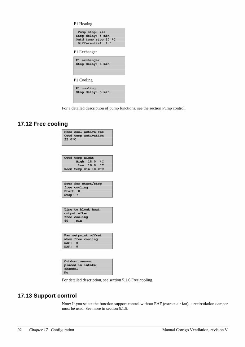
92 Chapter 17 Configuration Manual Corrigo Ventilation, revision V
P1 Heating
Pump stop: Yes Stop delay: 5 min Outd temp stop 10 °C Differential: 1.0
P1 Exchanger
P1 exchanger Stop delay: 5 min
P1 Cooling
P1 cooling Stop delay: 5 min
For a detailed description of pump functions, see the section Pump control.
17.12 Free cooling Free cool active:Yes Outd temp activation 22.0°C
Outd temp night High: 18.0 °C Low: 10.0 °C Room temp min 18.0°C
Hour for start/stop free cooling Start: 0 Stop: 7
Time to block heat output after free cooling 60 min
Fan setpoint offset when free cooling SAF: 0 EAF: 0
Outdoor sensor placed in intake channel No
For detailed description, see section 5.1.6 Free cooling.
17.13 Support control Note: If you select the function support control without EAF (extract air fan), a recirculation damper must be used. See more in section 5.1.5.
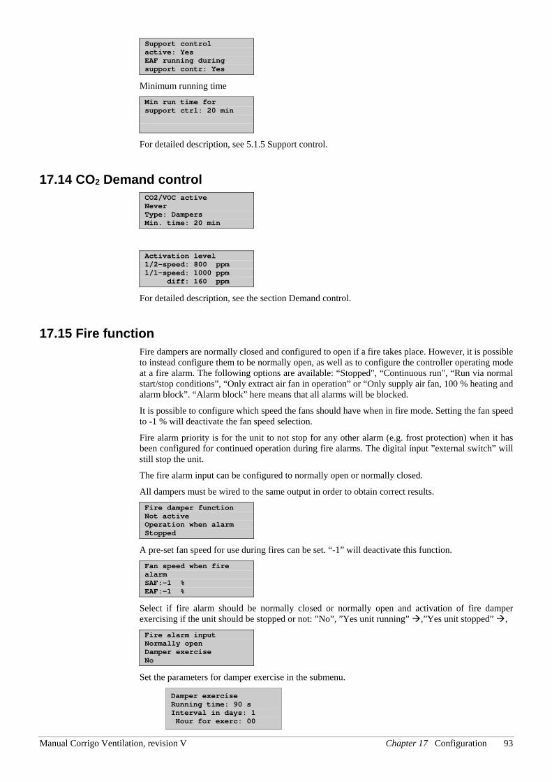
Manual Corrigo Ventilation, revision V Chapter 17 Configuration 93
Support control active: Yes EAF running during support contr: Yes
Minimum running time Min run time for support ctrl: 20 min
For detailed description, see 5.1.5 Support control.
17.14 CO2 Demand control CO2/VOC active Never Type: Dampers Min. time: 20 min
Activation level 1/2-speed: 800 ppm 1/1-speed: 1000 ppm diff: 160 ppm
For detailed description, see the section Demand control.
17.15 Fire function Fire dampers are normally closed and configured to open if a fire takes place. However, it is possible to instead configure them to be normally open, as well as to configure the controller operating mode at a fire alarm. The following options are available: “Stopped", “Continuous run", “Run via normal start/stop conditions”, “Only extract air fan in operation” or “Only supply air fan, 100 % heating and alarm block”. “Alarm block” here means that all alarms will be blocked.
It is possible to configure which speed the fans should have when in fire mode. Setting the fan speed to -1 % will deactivate the fan speed selection.
Fire alarm priority is for the unit to not stop for any other alarm (e.g. frost protection) when it has been configured for continued operation during fire alarms. The digital input ”external switch” will still stop the unit.
The fire alarm input can be configured to normally open or normally closed.
All dampers must be wired to the same output in order to obtain correct results. Fire damper function Not active Operation when alarm Stopped
A pre-set fan speed for use during fires can be set. “-1” will deactivate this function. Fan speed when fire alarm SAF:-1 % EAF:-1 %
Select if fire alarm should be normally closed or normally open and activation of fire damper exercising if the unit should be stopped or not: ”No”, ”Yes unit running” ,”Yes unit stopped” , Fire alarm input Normally open Damper exercise No
Set the parameters for damper exercise in the submenu.
Damper exercise Running time: 90 s Interval in days: 1 Hour for exerc: 00
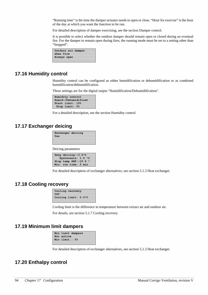
94 Chapter 17 Configuration Manual Corrigo Ventilation, revision V
“Running time” is the time the damper actuator needs to open or close. “Hour for exercise” is the hour of the day at which you want the function to be run.
For detailed description of damper exercising, see the section Damper control.
It is possible to select whether the outdoor damper should remain open or closed during an eventual fire. For the damper to remain open during fires, the running mode must be set to a setting other than “Stopped”. Outdoor air damper when fire Always open
17.16 Humidity control Humidity control can be configured as either humidification or dehumidification or as combined humidification/dehumidification.
These settings are for the digital output "Humidification/Dehumidification". Humidity control Humid-/Dehumidificat Start limit: 15% Stop limit: 5%
For a detailed description, see the section Humidity control.
17.17 Exchanger deicing Exchanger deicing Yes
Deicing parameters Setp deicing:-3.0°C Hysteresis: 1.0 °C Stop temp SAF:-10.0 ° Min. run time: 5 min
For detailed description of exchanger alternatives, see section 5.1.3 Heat exchanger.
17.18 Cooling recovery Cooling recovery Off Cooling limit: 0.0°C
Cooling limit is the difference in temperature between extract air and outdoor air.
For details, see section 5.1.7 Cooling recovery.
17.19 Minimum limit dampers Min limit dampers Not active Min limit.: 5%
For detailed description of exchanger alternatives, see section 5.1.3 Heat exchanger.
17.20 Enthalpy control
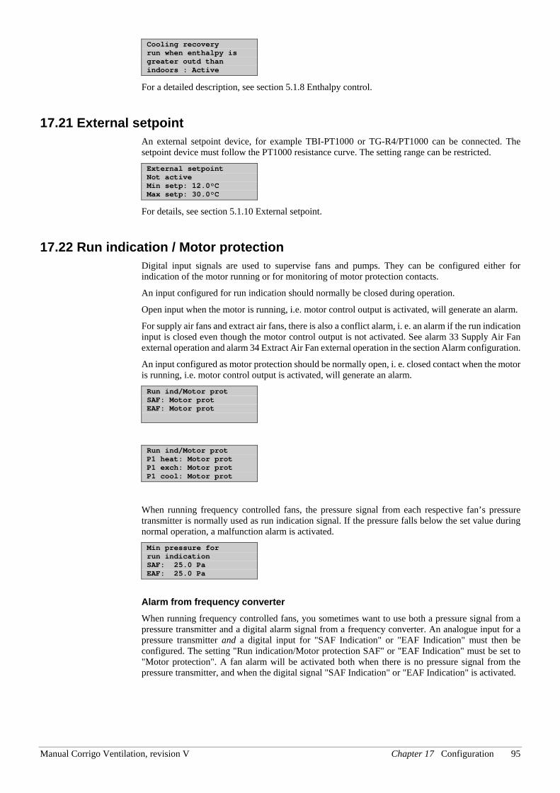
Manual Corrigo Ventilation, revision V Chapter 17 Configuration 95
Cooling recovery run when enthalpy is greater outd than indoors : Active
For a detailed description, see section 5.1.8 Enthalpy control.
17.21 External setpoint An external setpoint device, for example TBI-PT1000 or TG-R4/PT1000 can be connected. The setpoint device must follow the PT1000 resistance curve. The setting range can be restricted. External setpoint Not active Min setp: 12.0°C Max setp: 30.0°C
For details, see section 5.1.10 External setpoint.
17.22 Run indication / Motor protection Digital input signals are used to supervise fans and pumps. They can be configured either for indication of the motor running or for monitoring of motor protection contacts.
An input configured for run indication should normally be closed during operation.
Open input when the motor is running, i.e. motor control output is activated, will generate an alarm.
For supply air fans and extract air fans, there is also a conflict alarm, i. e. an alarm if the run indication input is closed even though the motor control output is not activated. See alarm 33 Supply Air Fan external operation and alarm 34 Extract Air Fan external operation in the section Alarm configuration.
An input configured as motor protection should be normally open, i. e. closed contact when the motor is running, i.e. motor control output is activated, will generate an alarm. Run ind/Motor prot SAF: Motor prot EAF: Motor prot
Run ind/Motor prot P1 heat: Motor prot P1 exch: Motor prot P1 cool: Motor prot
When running frequency controlled fans, the pressure signal from each respective fan’s pressure transmitter is normally used as run indication signal. If the pressure falls below the set value during normal operation, a malfunction alarm is activated. Min pressure for run indication SAF: 25.0 Pa EAF: 25.0 Pa
Alarm from frequency converter When running frequency controlled fans, you sometimes want to use both a pressure signal from a pressure transmitter and a digital alarm signal from a frequency converter. An analogue input for a pressure transmitter and a digital input for "SAF Indication" or "EAF Indication" must then be configured. The setting "Run indication/Motor protection SAF" or "EAF Indication" must be set to "Motor protection". A fan alarm will be activated both when there is no pressure signal from the pressure transmitter, and when the digital signal "SAF Indication" or "EAF Indication" is activated.
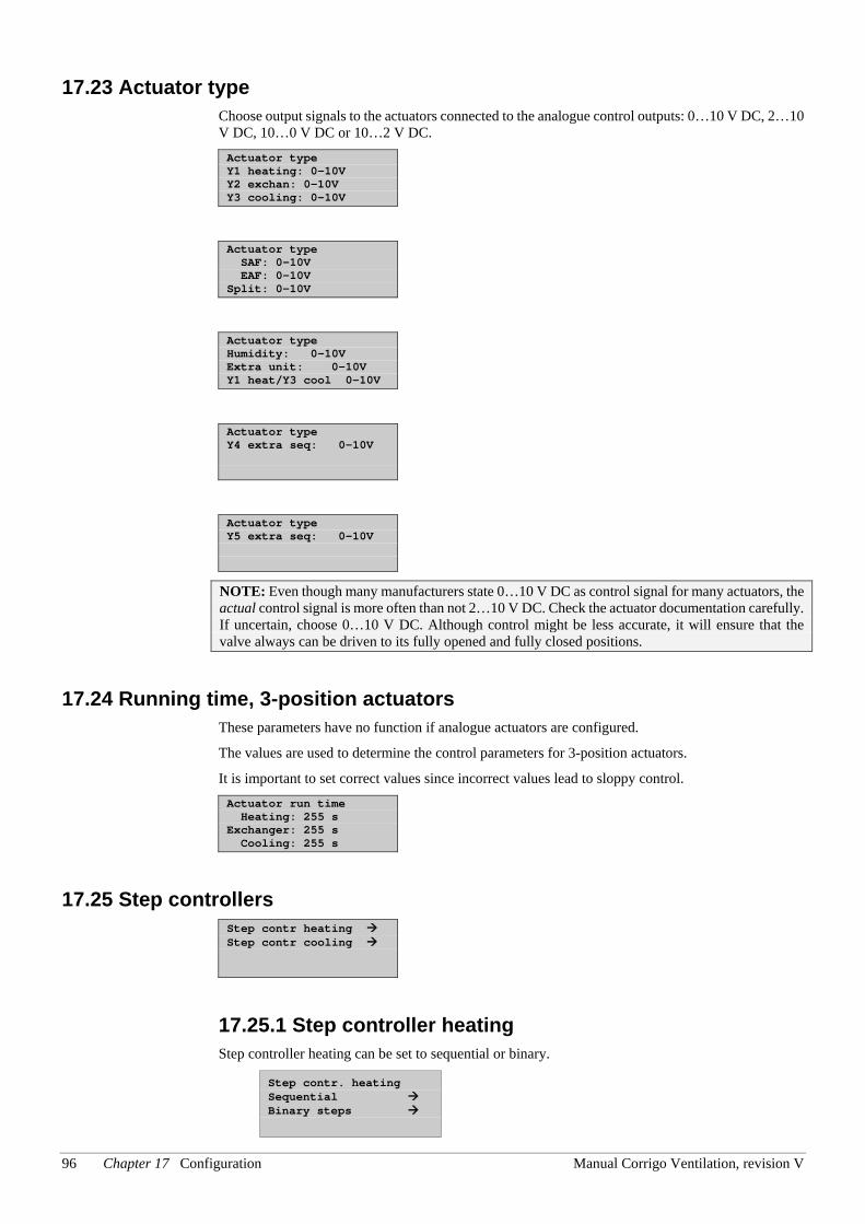
96 Chapter 17 Configuration Manual Corrigo Ventilation, revision V
17.23 Actuator type Choose output signals to the actuators connected to the analogue control outputs: 0…10 V DC, 2…10 V DC, 10…0 V DC or 10…2 V DC. Actuator type Y1 heating: 0-10V Y2 exchan: 0-10V Y3 cooling: 0-10V
Actuator type SAF: 0-10V EAF: 0-10V Split: 0-10V
Actuator type Humidity: 0-10V Extra unit: 0-10V Y1 heat/Y3 cool 0-10V
Actuator type Y4 extra seq: 0-10V
Actuator type Y5 extra seq: 0-10V
NOTE: Even though many manufacturers state 0…10 V DC as control signal for many actuators, the actual control signal is more often than not 2…10 V DC. Check the actuator documentation carefully. If uncertain, choose 0…10 V DC. Although control might be less accurate, it will ensure that the valve always can be driven to its fully opened and fully closed positions.
17.24 Running time, 3-position actuators These parameters have no function if analogue actuators are configured.
The values are used to determine the control parameters for 3-position actuators.
It is important to set correct values since incorrect values lead to sloppy control. Actuator run time Heating: 255 s Exchanger: 255 s Cooling: 255 s
17.25 Step controllers Step contr heating Step contr cooling
17.25.1 Step controller heating Step controller heating can be set to sequential or binary.
Step contr. heating Sequential Binary steps
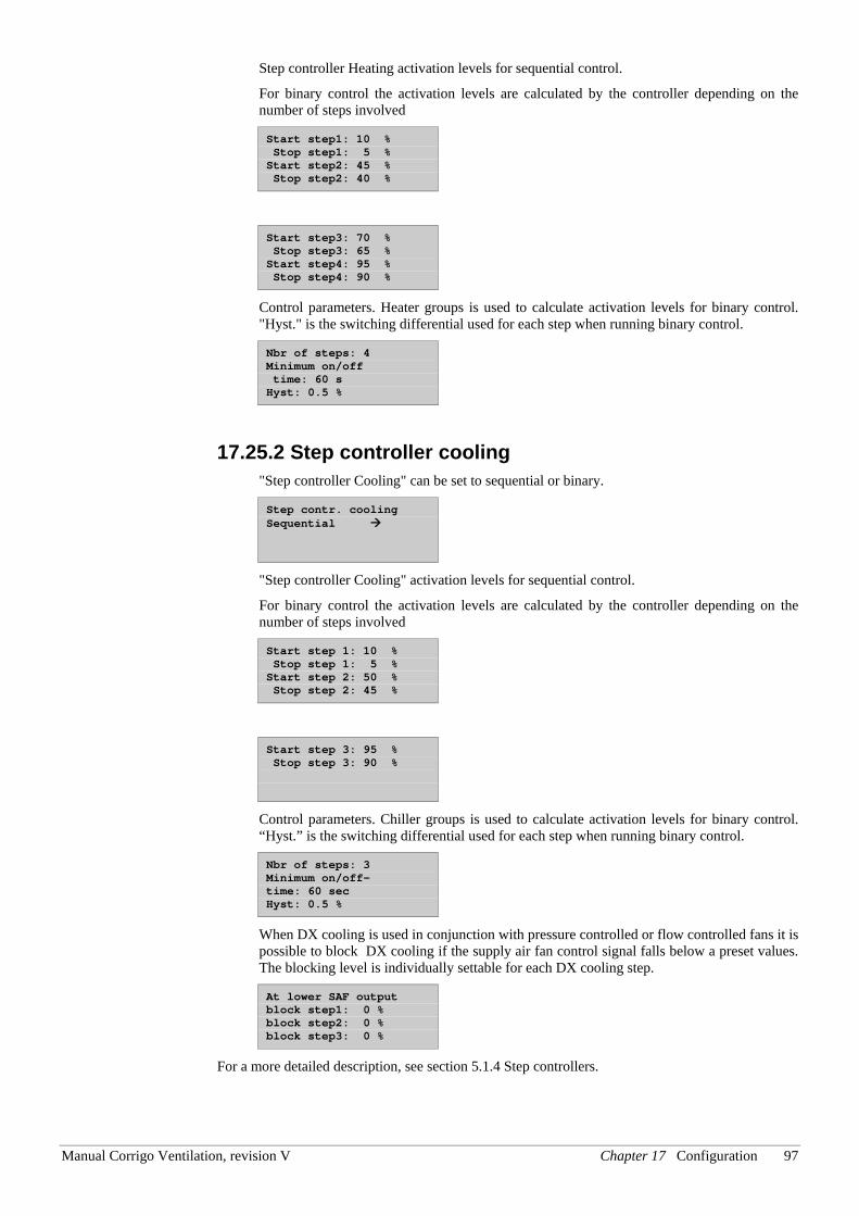
Manual Corrigo Ventilation, revision V Chapter 17 Configuration 97
Step controller Heating activation levels for sequential control.
For binary control the activation levels are calculated by the controller depending on the number of steps involved
Start step1: 10 % Stop step1: 5 % Start step2: 45 % Stop step2: 40 %
Start step3: 70 % Stop step3: 65 % Start step4: 95 % Stop step4: 90 %
Control parameters. Heater groups is used to calculate activation levels for binary control. "Hyst." is the switching differential used for each step when running binary control.
Nbr of steps: 4 Minimum on/off time: 60 s Hyst: 0.5 %
17.25.2 Step controller cooling "Step controller Cooling" can be set to sequential or binary.
Step contr. cooling Sequential
"Step controller Cooling" activation levels for sequential control.
For binary control the activation levels are calculated by the controller depending on the number of steps involved
Start step 1: 10 % Stop step 1: 5 % Start step 2: 50 % Stop step 2: 45 %
Start step 3: 95 % Stop step 3: 90 %
Control parameters. Chiller groups is used to calculate activation levels for binary control. “Hyst.” is the switching differential used for each step when running binary control.
Nbr of steps: 3 Minimum on/off- time: 60 sec Hyst: 0.5 %
When DX cooling is used in conjunction with pressure controlled or flow controlled fans it is possible to block DX cooling if the supply air fan control signal falls below a preset values. The blocking level is individually settable for each DX cooling step.
At lower SAF output block step1: 0 % block step2: 0 % block step3: 0 %
For a more detailed description, see section 5.1.4 Step controllers.
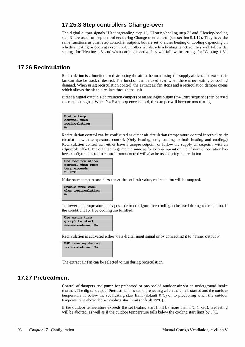
98 Chapter 17 Configuration Manual Corrigo Ventilation, revision V
17.25.3 Step controllers Change-over The digital output signals "Heating/cooling step 1", "Heating/cooling step 2" and "Heating/cooling step 3" are used for step controllers during Change-over control (see section 5.1.12). They have the same functions as other step controller outputs, but are set to either heating or cooling depending on whether heating or cooling is required. In other words, when heating is active, they will follow the settings for "Heating 1-3" and when cooling is active they will follow the settings for "Cooling 1-3".
17.26 Recirculation Recirculation is a function for distributing the air in the room using the supply air fan. The extract air fan can also be used, if desired. The function can be used even when there is no heating or cooling demand. When using recirculation control, the extract air fan stops and a recirculation damper opens which allows the air to circulate through the unit.
Either a digital output (Recirculation damper) or an analogue output (Y4 Extra sequence) can be used as an output signal. When Y4 Extra sequence is used, the damper will become modulating.
Enable temp control when recirculation No
Recirculation control can be configured as either air circulation (temperature control inactive) or air circulation with temperature control. (Only heating, only cooling or both heating and cooling.) Recirculation control can either have a unique setpoint or follow the supply air setpoint, with an adjustable offset. The other settings are the same as for normal operation, i.e. if normal operation has been configured as room control, room control will also be used during recirculation. End recirculation control when room temp exceeds: 25.0°C
If the room temperature rises above the set limit value, recirculation will be stopped. Enable free cool when recirculation No
To lower the temperature, it is possible to configure free cooling to be used during recirculation, if the conditions for free cooling are fulfilled. Use extra time group5 to start recirculation: No
Recirculation is activated either via a digital input signal or by connecting it to "Timer output 5". EAF running during recirculation: No
The extract air fan can be selected to run during recirculation.
17.27 Pretreatment Control of dampers and pump for preheated or pre-cooled outdoor air via an underground intake channel. The digital output ”Pretreatment” is set to preheating when the unit is started and the outdoor temperature is below the set heating start limit (default 8°C) or to precooling when the outdoor temperature is above the set cooling start limit (default 19°C).
If the outdoor temperature exceeds the set heating start limit by more than 1°C (fixed), preheating will be aborted, as well as if the outdoor temperature falls below the cooling start limit by 1°C.
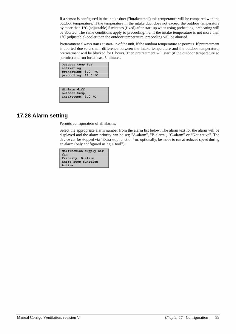
Manual Corrigo Ventilation, revision V Chapter 17 Configuration 99
If a sensor is configured in the intake duct (”intaketemp”) this temperature will be compared with the outdoor temperature. If the temperature in the intake duct does not exceed the outdoor temperature by more than 1°C (adjustable) 5 minutes (fixed) after start-up when using preheating, preheating will be aborted. The same conditions apply to precooling, i.e. if the intake temperature is not more than 1°C (adjustable) cooler than the outdoor temperature, precooling will be aborted.
Pretreatment always starts at start-up of the unit, if the outdoor temperature so permits. If pretreatment is aborted due to a small difference between the intake temperature and the outdoor temperature, pretreatment will be blocked for 6 hours. Then pretreatment will start (if the outdoor temperature so permits) and run for at least 5 minutes. Outdoor temp for activating preheating: 8.0 °C precooling: 19.0 °C
Minimum diff outdoor temp- intaketemp: 1.0 °C
17.28 Alarm setting Permits configuration of all alarms.
Select the appropriate alarm number from the alarm list below. The alarm text for the alarm will be displayed and the alarm priority can be set; "A-alarm", "B-alarm", "C-alarm” or “Not active". The device can be stopped via “Extra stop function” or, optionally, be made to run at reduced speed during an alarm (only configured using E tool©). Malfunction supply air fan Priority: B-alarm Extra stop function Active
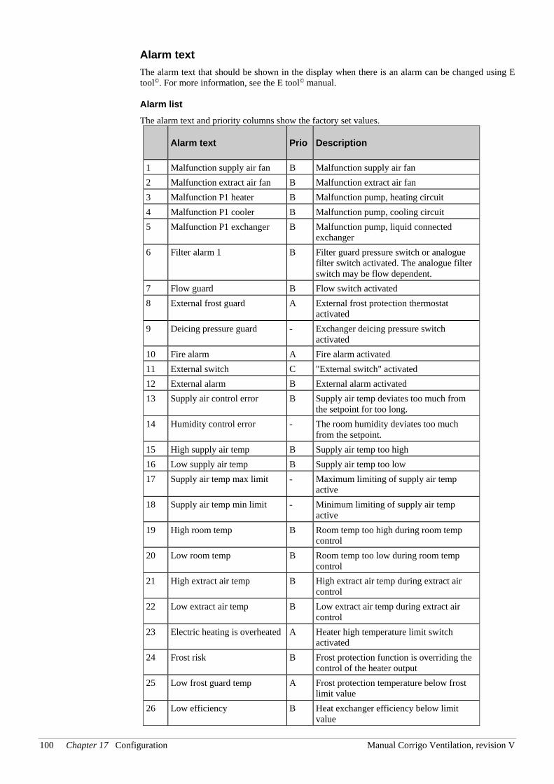
100 Chapter 17 Configuration Manual Corrigo Ventilation, revision V
Alarm text The alarm text that should be shown in the display when there is an alarm can be changed using E tool©. For more information, see the E tool© manual. Alarm list The alarm text and priority columns show the factory set values.
Alarm text Prio Description
1 Malfunction supply air fan B Malfunction supply air fan 2 Malfunction extract air fan B Malfunction extract air fan 3 Malfunction P1 heater B Malfunction pump, heating circuit 4 Malfunction P1 cooler B Malfunction pump, cooling circuit 5 Malfunction P1 exchanger B Malfunction pump, liquid connected
exchanger 6 Filter alarm 1 B Filter guard pressure switch or analogue
filter switch activated. The analogue filter switch may be flow dependent.
7 Flow guard B Flow switch activated 8 External frost guard A External frost protection thermostat
activated 9 Deicing pressure guard - Exchanger deicing pressure switch
activated 10 Fire alarm A Fire alarm activated 11 External switch C "External switch" activated 12 External alarm B External alarm activated 13 Supply air control error B Supply air temp deviates too much from
the setpoint for too long. 14 Humidity control error - The room humidity deviates too much
from the setpoint. 15 High supply air temp B Supply air temp too high 16 Low supply air temp B Supply air temp too low 17 Supply air temp max limit - Maximum limiting of supply air temp
active 18 Supply air temp min limit - Minimum limiting of supply air temp
active 19 High room temp B Room temp too high during room temp
control 20 Low room temp B Room temp too low during room temp
control 21 High extract air temp B High extract air temp during extract air
control 22 Low extract air temp B Low extract air temp during extract air
control 23 Electric heating is overheated A Heater high temperature limit switch
activated 24 Frost risk B Frost protection function is overriding the
control of the heater output 25 Low frost guard temp A Frost protection temperature below frost
limit value 26 Low efficiency B Heat exchanger efficiency below limit
value
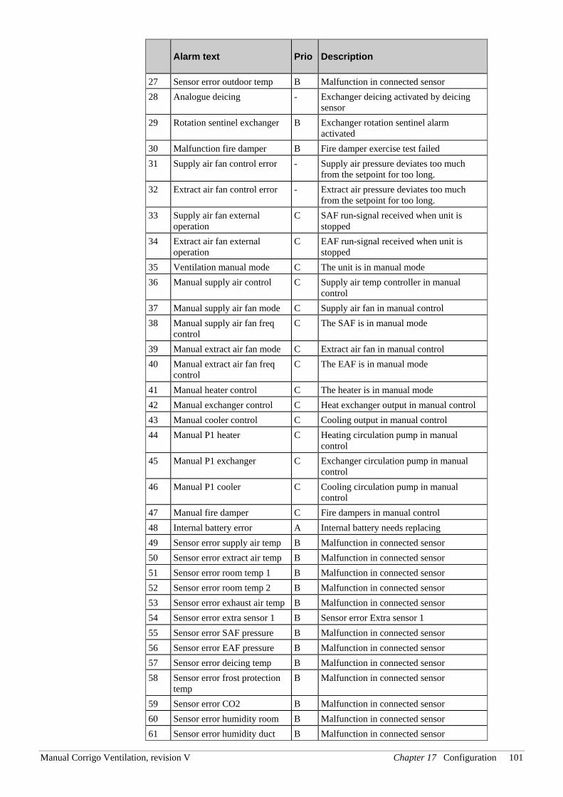
Manual Corrigo Ventilation, revision V Chapter 17 Configuration 101
Alarm text Prio Description
27 Sensor error outdoor temp B Malfunction in connected sensor 28 Analogue deicing - Exchanger deicing activated by deicing
sensor 29 Rotation sentinel exchanger B Exchanger rotation sentinel alarm
activated 30 Malfunction fire damper B Fire damper exercise test failed 31 Supply air fan control error - Supply air pressure deviates too much
from the setpoint for too long. 32 Extract air fan control error - Extract air pressure deviates too much
from the setpoint for too long. 33 Supply air fan external
operation C SAF run-signal received when unit is
stopped 34 Extract air fan external
operation C EAF run-signal received when unit is
stopped 35 Ventilation manual mode C The unit is in manual mode 36 Manual supply air control C Supply air temp controller in manual
control 37 Manual supply air fan mode C Supply air fan in manual control 38 Manual supply air fan freq
control C The SAF is in manual mode
39 Manual extract air fan mode C Extract air fan in manual control 40 Manual extract air fan freq
control C The EAF is in manual mode
41 Manual heater control C The heater is in manual mode 42 Manual exchanger control C Heat exchanger output in manual control 43 Manual cooler control C Cooling output in manual control 44 Manual P1 heater C Heating circulation pump in manual
control 45 Manual P1 exchanger C Exchanger circulation pump in manual
control 46 Manual P1 cooler C Cooling circulation pump in manual
control 47 Manual fire damper C Fire dampers in manual control 48 Internal battery error A Internal battery needs replacing 49 Sensor error supply air temp B Malfunction in connected sensor 50 Sensor error extract air temp B Malfunction in connected sensor 51 Sensor error room temp 1 B Malfunction in connected sensor 52 Sensor error room temp 2 B Malfunction in connected sensor 53 Sensor error exhaust air temp B Malfunction in connected sensor 54 Sensor error extra sensor 1 B Sensor error Extra sensor 1 55 Sensor error SAF pressure B Malfunction in connected sensor 56 Sensor error EAF pressure B Malfunction in connected sensor 57 Sensor error deicing temp B Malfunction in connected sensor 58 Sensor error frost protection
temp B Malfunction in connected sensor
59 Sensor error CO2 B Malfunction in connected sensor 60 Sensor error humidity room B Malfunction in connected sensor 61 Sensor error humidity duct B Malfunction in connected sensor
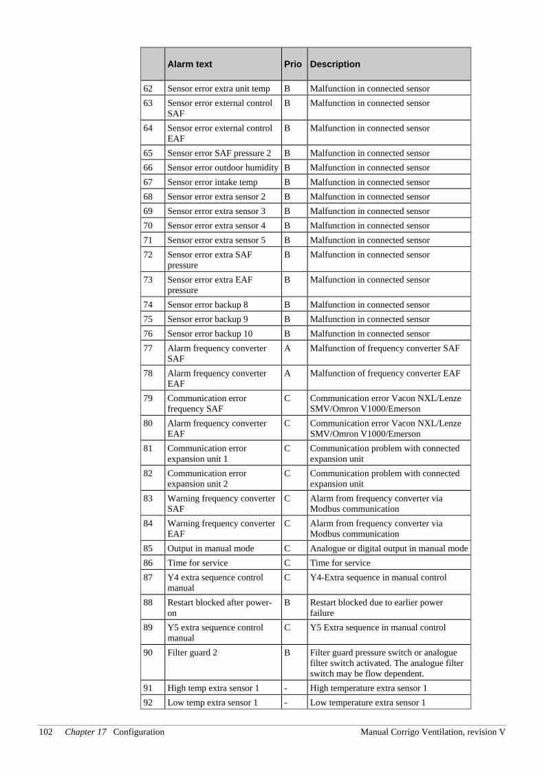
102 Chapter 17 Configuration Manual Corrigo Ventilation, revision V
Alarm text Prio Description
62 Sensor error extra unit temp B Malfunction in connected sensor 63 Sensor error external control
SAF B Malfunction in connected sensor
64 Sensor error external control EAF
B Malfunction in connected sensor
65 Sensor error SAF pressure 2 B Malfunction in connected sensor 66 Sensor error outdoor humidity B Malfunction in connected sensor 67 Sensor error intake temp B Malfunction in connected sensor 68 Sensor error extra sensor 2 B Malfunction in connected sensor 69 Sensor error extra sensor 3 B Malfunction in connected sensor 70 Sensor error extra sensor 4 B Malfunction in connected sensor 71 Sensor error extra sensor 5 B Malfunction in connected sensor 72 Sensor error extra SAF
pressure B Malfunction in connected sensor
73 Sensor error extra EAF pressure
B Malfunction in connected sensor
74 Sensor error backup 8 B Malfunction in connected sensor 75 Sensor error backup 9 B Malfunction in connected sensor 76 Sensor error backup 10 B Malfunction in connected sensor 77 Alarm frequency converter
SAF A Malfunction of frequency converter SAF
78 Alarm frequency converter EAF
A Malfunction of frequency converter EAF
79 Communication error frequency SAF
C Communication error Vacon NXL/Lenze SMV/Omron V1000/Emerson
80 Alarm frequency converter EAF
C Communication error Vacon NXL/Lenze SMV/Omron V1000/Emerson
81 Communication error expansion unit 1
C Communication problem with connected expansion unit
82 Communication error expansion unit 2
C Communication problem with connected expansion unit
83 Warning frequency converter SAF
C Alarm from frequency converter via Modbus communication
84 Warning frequency converter EAF
C Alarm from frequency converter via Modbus communication
85 Output in manual mode C Analogue or digital output in manual mode 86 Time for service C Time for service 87 Y4 extra sequence control
manual C Y4-Extra sequence in manual control
88 Restart blocked after power-on
B Restart blocked due to earlier power failure
89 Y5 extra sequence control manual
C Y5 Extra sequence in manual control
90 Filter guard 2 B Filter guard pressure switch or analogue filter switch activated. The analogue filter switch may be flow dependent.
91 High temp extra sensor 1 - High temperature extra sensor 1 92 Low temp extra sensor 1 - Low temperature extra sensor 1
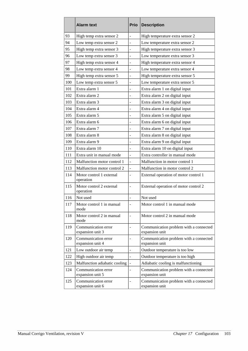
Manual Corrigo Ventilation, revision V Chapter 17 Configuration 103
Alarm text Prio Description
93 High temp extra sensor 2 - High temperature extra sensor 2 94 Low temp extra sensor 2 - Low temperature extra sensor 2 95 High temp extra sensor 3 - High temperature extra sensor 3 96 Low temp extra sensor 3 - Low temperature extra sensor 3 97 High temp extra sensor 4 - High temperature extra sensor 4 98 Low temp extra sensor 4 - Low temperature extra sensor 4 99 High temp extra sensor 5 - High temperature extra sensor 5 100 Low temp extra sensor 5 - Low temperature extra sensor 5 101 Extra alarm 1 - Extra alarm 1 on digital input 102 Extra alarm 2 - Extra alarm 2 on digital input 103 Extra alarm 3 - Extra alarm 3 on digital input 104 Extra alarm 4 - Extra alarm 4 on digital input 105 Extra alarm 5 - Extra alarm 5 on digital input 106 Extra alarm 6 - Extra alarm 6 on digital input 107 Extra alarm 7 - Extra alarm 7 on digital input 108 Extra alarm 8 - Extra alarm 8 on digital input 109 Extra alarm 9 - Extra alarm 9 on digital input 110 Extra alarm 10 - Extra alarm 10 on digital input 111 Extra unit in manual mode - Extra controller in manual mode 112 Malfunction motor control 1 - Malfunction in motor control 1 113 Malfunction motor control 2 - Malfunction in motor control 2 114 Motor control 1 external
operation - External operation of motor control 1
115 Motor control 2 external operation
- External operation of motor control 2
116 Not used - Not used 117 Motor control 1 in manual
mode - Motor control 1 in manual mode
118 Motor control 2 in manual mode
- Motor control 2 in manual mode
119 Communication error expansion unit 3
- Communication problem with a connected expansion unit
120 Communication error expansion unit 4
- Communication problem with a connected expansion unit
121 Low outdoor air temp - Outdoor temperature is too low 122 High outdoor air temp - Outdoor temperature is too high 123 Malfunction adiabatic cooling - Adiabatic cooling is malfunctioning 124 Communication error
expansion unit 5 - Communication problem with a connected
expansion unit 125 Communication error
expansion unit 6 - Communication problem with a connected
expansion unit
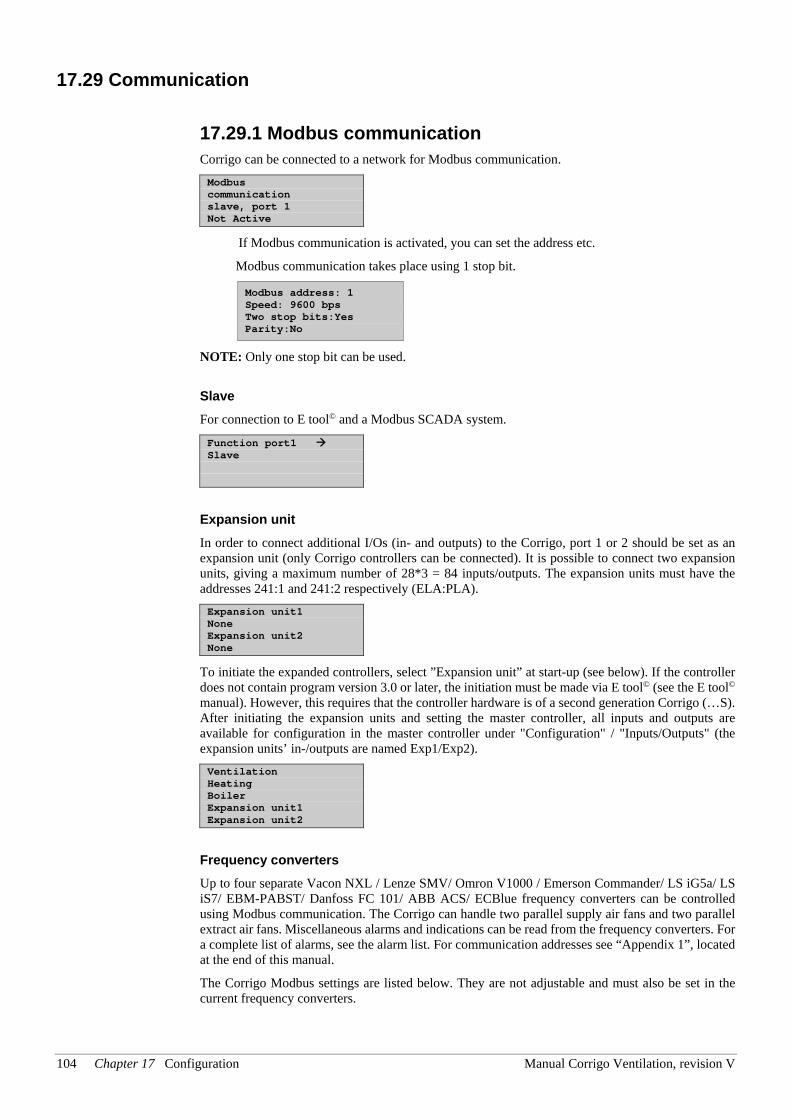
104 Chapter 17 Configuration Manual Corrigo Ventilation, revision V
17.29 Communication
17.29.1 Modbus communication Corrigo can be connected to a network for Modbus communication. Modbus communication slave, port 1 Not Active
If Modbus communication is activated, you can set the address etc.
Modbus communication takes place using 1 stop bit.
Modbus address: 1 Speed: 9600 bps Two stop bits:Yes Parity:No
NOTE: Only one stop bit can be used.
Slave For connection to E tool© and a Modbus SCADA system.
Function port1 Slave
Expansion unit In order to connect additional I/Os (in- and outputs) to the Corrigo, port 1 or 2 should be set as an expansion unit (only Corrigo controllers can be connected). It is possible to connect two expansion units, giving a maximum number of 28*3 = 84 inputs/outputs. The expansion units must have the addresses 241:1 and 241:2 respectively (ELA:PLA). Expansion unit1 None Expansion unit2 None
To initiate the expanded controllers, select ”Expansion unit” at start-up (see below). If the controller does not contain program version 3.0 or later, the initiation must be made via E tool© (see the E tool© manual). However, this requires that the controller hardware is of a second generation Corrigo (…S). After initiating the expansion units and setting the master controller, all inputs and outputs are available for configuration in the master controller under "Configuration" / "Inputs/Outputs" (the expansion units’ in-/outputs are named Exp1/Exp2). Ventilation Heating Boiler Expansion unit1 Expansion unit2
Frequency converters Up to four separate Vacon NXL / Lenze SMV/ Omron V1000 / Emerson Commander/ LS iG5a/ LS iS7/ EBM-PABST/ Danfoss FC 101/ ABB ACS/ ECBlue frequency converters can be controlled using Modbus communication. The Corrigo can handle two parallel supply air fans and two parallel extract air fans. Miscellaneous alarms and indications can be read from the frequency converters. For a complete list of alarms, see the alarm list. For communication addresses see “Appendix 1”, located at the end of this manual.
The Corrigo Modbus settings are listed below. They are not adjustable and must also be set in the current frequency converters.
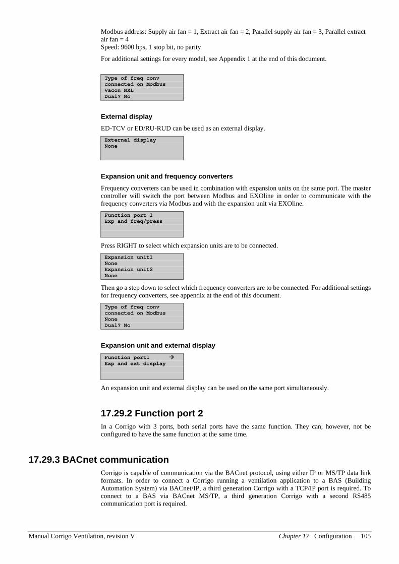
Manual Corrigo Ventilation, revision V Chapter 17 Configuration 105
Modbus address: Supply air fan = 1, Extract air fan = 2, Parallel supply air fan = 3, Parallel extract air fan = 4 Speed: 9600 bps, 1 stop bit, no parity
For additional settings for every model, see Appendix 1 at the end of this document. Type of freq conv connected on Modbus Vacon NXL Dual? No
External display
ED-TCV or ED/RU-RUD can be used as an external display. External display None
Expansion unit and frequency converters Frequency converters can be used in combination with expansion units on the same port. The master controller will switch the port between Modbus and EXOline in order to communicate with the frequency converters via Modbus and with the expansion unit via EXOline. Function port 1 Exp and freq/press
Press RIGHT to select which expansion units are to be connected. Expansion unit1 None Expansion unit2 None
Then go a step down to select which frequency converters are to be connected. For additional settings for frequency converters, see appendix at the end of this document. Type of freq conv connected on Modbus None Dual? No
Expansion unit and external display Function port1 Exp and ext display
An expansion unit and external display can be used on the same port simultaneously.
17.29.2 Function port 2 In a Corrigo with 3 ports, both serial ports have the same function. They can, however, not be configured to have the same function at the same time.
17.29.3 BACnet communication Corrigo is capable of communication via the BACnet protocol, using either IP or MS/TP data link formats. In order to connect a Corrigo running a ventilation application to a BAS (Building Automation System) via BACnet/IP, a third generation Corrigo with a TCP/IP port is required. To connect to a BAS via BACnet MS/TP, a third generation Corrigo with a second RS485 communication port is required.
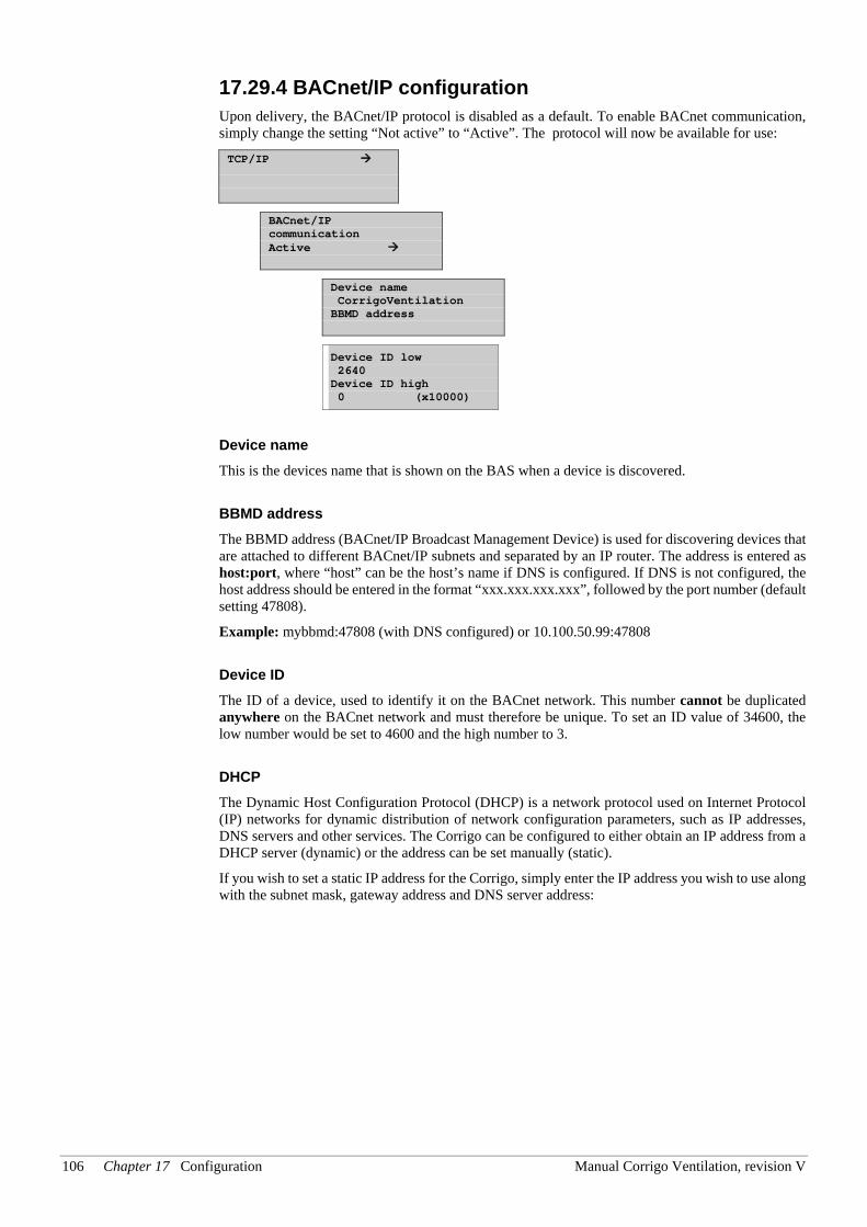
106 Chapter 17 Configuration Manual Corrigo Ventilation, revision V
17.29.4 BACnet/IP configuration Upon delivery, the BACnet/IP protocol is disabled as a default. To enable BACnet communication, simply change the setting “Not active” to “Active”. The protocol will now be available for use:
TCP/IP
BACnet/IP communication Active
Device name CorrigoVentilation BBMD address
Device ID low 2640 Device ID high 0 (x10000)
Device name This is the devices name that is shown on the BAS when a device is discovered.
BBMD address The BBMD address (BACnet/IP Broadcast Management Device) is used for discovering devices that are attached to different BACnet/IP subnets and separated by an IP router. The address is entered as host:port, where “host” can be the host’s name if DNS is configured. If DNS is not configured, the host address should be entered in the format “xxx.xxx.xxx.xxx”, followed by the port number (default setting 47808).
Example: mybbmd:47808 (with DNS configured) or 10.100.50.99:47808
Device ID The ID of a device, used to identify it on the BACnet network. This number cannot be duplicated anywhere on the BACnet network and must therefore be unique. To set an ID value of 34600, the low number would be set to 4600 and the high number to 3.
DHCP The Dynamic Host Configuration Protocol (DHCP) is a network protocol used on Internet Protocol (IP) networks for dynamic distribution of network configuration parameters, such as IP addresses, DNS servers and other services. The Corrigo can be configured to either obtain an IP address from a DHCP server (dynamic) or the address can be set manually (static). If you wish to set a static IP address for the Corrigo, simply enter the IP address you wish to use along with the subnet mask, gateway address and DNS server address:
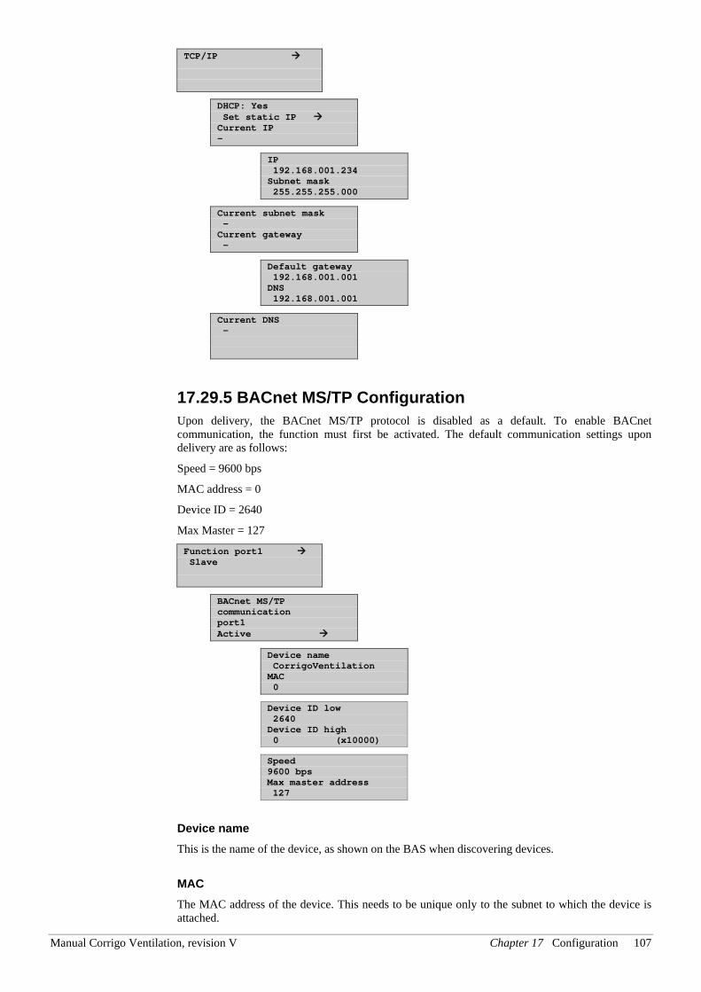
Manual Corrigo Ventilation, revision V Chapter 17 Configuration 107
TCP/IP
DHCP: Yes Set static IP Current IP -
IP 192.168.001.234 Subnet mask 255.255.255.000
Current subnet mask - Current gateway -
Default gateway 192.168.001.001 DNS 192.168.001.001
Current DNS -
17.29.5 BACnet MS/TP Configuration Upon delivery, the BACnet MS/TP protocol is disabled as a default. To enable BACnet communication, the function must first be activated. The default communication settings upon delivery are as follows:
Speed = 9600 bps
MAC address = 0
Device ID = 2640
Max Master = 127
Function port1 Slave
BACnet MS/TP communication port1 Active
Device name CorrigoVentilation MAC 0
Device ID low 2640 Device ID high 0 (x10000)
Speed 9600 bps Max master address 127
Device name This is the name of the device, as shown on the BAS when discovering devices.
MAC The MAC address of the device. This needs to be unique only to the subnet to which the device is attached.
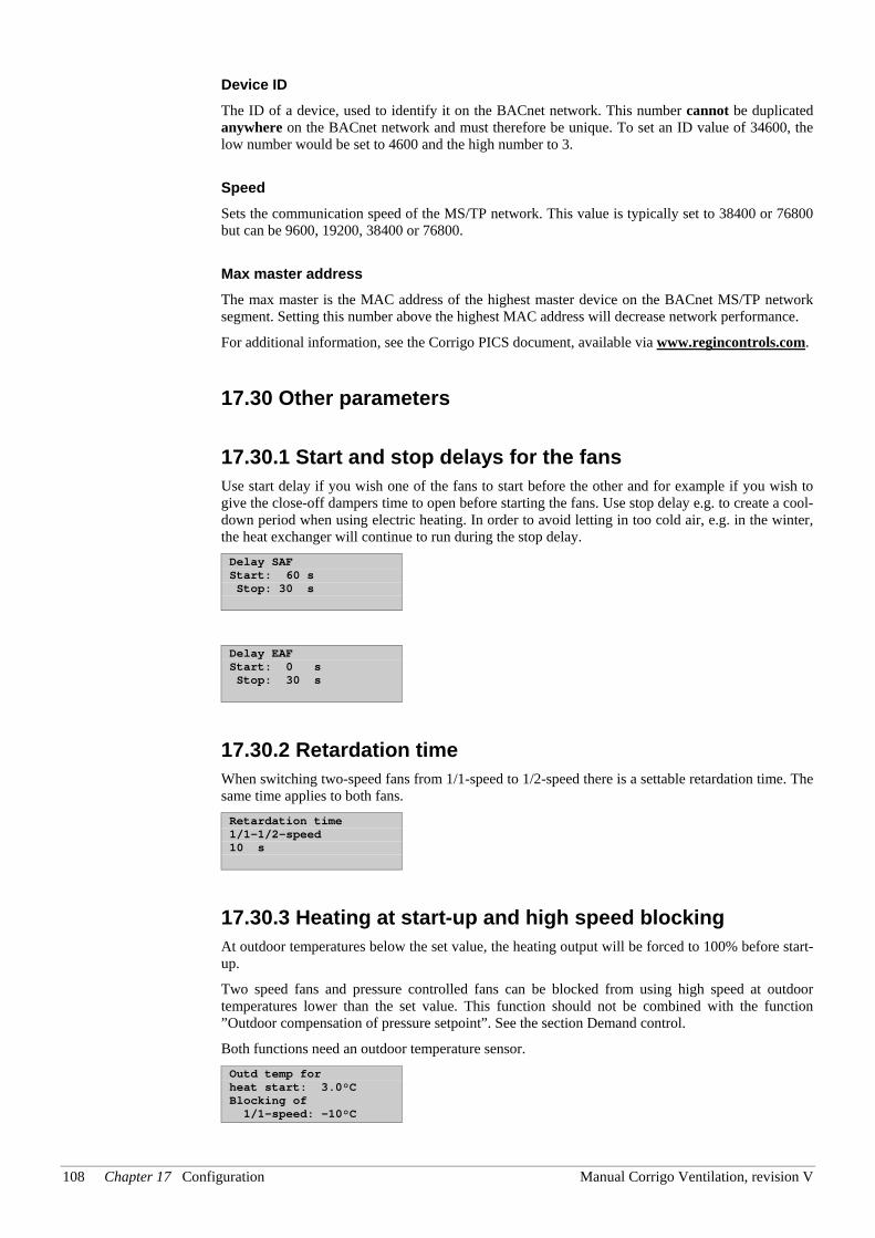
108 Chapter 17 Configuration Manual Corrigo Ventilation, revision V
Device ID The ID of a device, used to identify it on the BACnet network. This number cannot be duplicated anywhere on the BACnet network and must therefore be unique. To set an ID value of 34600, the low number would be set to 4600 and the high number to 3.
Speed Sets the communication speed of the MS/TP network. This value is typically set to 38400 or 76800 but can be 9600, 19200, 38400 or 76800.
Max master address The max master is the MAC address of the highest master device on the BACnet MS/TP network segment. Setting this number above the highest MAC address will decrease network performance.
For additional information, see the Corrigo PICS document, available via www.regincontrols.com.
17.30 Other parameters
17.30.1 Start and stop delays for the fans Use start delay if you wish one of the fans to start before the other and for example if you wish to give the close-off dampers time to open before starting the fans. Use stop delay e.g. to create a cool-down period when using electric heating. In order to avoid letting in too cold air, e.g. in the winter, the heat exchanger will continue to run during the stop delay. Delay SAF Start: 60 s Stop: 30 s
Delay EAF Start: 0 s Stop: 30 s
17.30.2 Retardation time When switching two-speed fans from 1/1-speed to 1/2-speed there is a settable retardation time. The same time applies to both fans. Retardation time 1/1-1/2-speed 10 s
17.30.3 Heating at start-up and high speed blocking At outdoor temperatures below the set value, the heating output will be forced to 100% before start-up.
Two speed fans and pressure controlled fans can be blocked from using high speed at outdoor temperatures lower than the set value. This function should not be combined with the function ”Outdoor compensation of pressure setpoint”. See the section Demand control.
Both functions need an outdoor temperature sensor. Outd temp for heat start: 3.0°C Blocking of 1/1-speed: -10°C
Manual Corrigo Ventilation, revision V Chapter 17 Configuration 109
17.30.4 Start delay exchanger Start delay exch 0 s
17.30.5 Exchanger to 100% at start and alarm delay at start To minimise the risk of freeze-up problems, the heat exchanger can be forced to maximum capacity for the set time at start-up.
To eliminate the risk of, for example, fan pressure alarms at start-up, all alarm functions can be suppressed for the set time. Exch 100% at start 2 s Alarm delay at start 60 s
For the function ”Slave control of the extract air fan”, the fan will start directly at 50 % after the start delay, in order for the heating of the exchanger to work for this operating mode. When the supply air fan starts, the extract air fan will be slave controlled by the flow in the supply air duct.
17.30.6 Split controller signal Splits the controller output (Heating Controller Output signal = HCOut) between the analogue temperature control output signals Y1, Y2 and Y3 for "Heating", "Heat exchanger" and "Cooling", "Y4" and "Y5".
To create a neutral zone, leave a percentage gap between sequences.
The set P-band for the supply air controller is for the whole controller signal. This means that the P-band for each sequence is proportionate to the split percentage values given to sequences.
Example: P-band for the supply air controller is set to 33K. The HCOut is set so that cooling gets 0…30 % = 30 %, the exchanger gets 32…50 % = 18 % and the heater gets 54…100 % = 46 %. The individual P-bands will then be:
Chiller: 30 % of 33°C = 10°C
Exchanger: 18 % of 33°C = 6°C
Heating: 46 % of 33°C = 15°C
The remaining 2°C are the neutral zone between cooling and exchanger and between exchanger and heating.
Split settings exchanger 0% at HCOut= 32% 100% at HCOut= 50%
Split settings heating 0% at HCOut= 54% 100% at HCOut= 100%
Split settings cooling 0% at HCOut= 30% 100% at HCOut= 0%
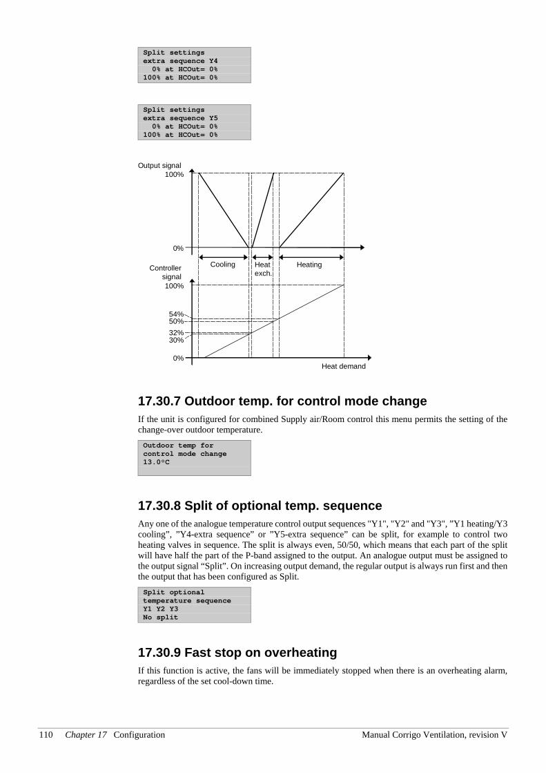
110 Chapter 17 Configuration Manual Corrigo Ventilation, revision V
Split settings extra sequence Y4 0% at HCOut= 0% 100% at HCOut= 0%
Split settings extra sequence Y5 0% at HCOut= 0% 100% at HCOut= 0%
17.30.7 Outdoor temp. for control mode change If the unit is configured for combined Supply air/Room control this menu permits the setting of the change-over outdoor temperature. Outdoor temp for control mode change 13.0°C
17.30.8 Split of optional temp. sequence Any one of the analogue temperature control output sequences "Y1", "Y2" and "Y3", ”Y1 heating/Y3 cooling”, ”Y4-extra sequence” or ”Y5-extra sequence” can be split, for example to control two heating valves in sequence. The split is always even, 50/50, which means that each part of the split will have half the part of the P-band assigned to the output. An analogue output must be assigned to the output signal “Split”. On increasing output demand, the regular output is always run first and then the output that has been configured as Split. Split optional temperature sequence Y1 Y2 Y3 No split
17.30.9 Fast stop on overheating If this function is active, the fans will be immediately stopped when there is an overheating alarm, regardless of the set cool-down time.
54%50%32%30%
0%
0%
Controllersignal
Cooling HeatingHeatexch.
Output signal100%
100%
Heat demand
Manual Corrigo Ventilation, revision V Chapter 17 Configuration 111
Fast stop on alarm “Electric heating is overheated”: No
17.30.10 Automatic restart at power-up The function ”Automatic restart at power-up” makes it possible to block automatic restart of the unit at power-up. At power-up, the B-alarm ”Restart blocked after power on” is generated. Once this alarm has been acknowledged, the unit will start. Automatically restart after power-on: Yes
17.31 System
17.31.1 Change language Use this menu to change the display language. Choose language English
Note, this menu is also directly accessible by holding the OK-button depressed during power-up or by pressing right arrow three times when the start display is shown.
The different language files are stored in the application memory and are downloaded to the work memory. If a Corrigo via E tool© has been reloaded with a newer program revision than the factory revision, the controller will not allow language files to be downloaded from the application memory. This is because there is a risk that the language files are not compatible with the new revision. Therefore, you are limited to the two languages you have downloaded using E tool©.
17.31.2 Choose start display, the text normally shown on the display There are five different to choose from.
Type 1 The text on the first line can be changed using E tool©.
The second line shows the date and time.
The third line shows the present running status.
The fourth line shows the present temperature setpoint and actual values. Vent unit 18 PX 2004-08-15 11:28 System: Running Sp:22.0°C Act:21.8°C
Type 2 The first line shows the date and time.
The second line shows the present running status.
The third line shows the present temperature setpoint and actual values.
The fourth line shows the present temperature control output values.
112 Chapter 17 Configuration Manual Corrigo Ventilation, revision V
2004-08-15 11:28 System: Running Sp:22.0°C Act:21.8°C Y1:0% Y2:93% Y3:0%
Type 3 The first line shows the date and time.
The second line shows the present running status.
The third line shows the present temperature setpoint and actual values.
The fourth line shows the present SAF and EAF pressures. 15/03/2004 11:28 System: Running Sp:22.0°C Act:21.8°C SF:1100Pa EF:1050Pa
Type 4 The text on the first line can be changed using E tool©.
The second line shows the date and time.
The third line shows the present running status. Vent unit 18 PX 2004-03-15 11:28 System: Running
Type 5 The text on the first line can be changed using E tool©.
The second line shows the date and time. Vent unit 18 PX 2004-03-15 11:28
17.31.3 Automatic summer-/wintertime change-over When Corrigo is set on automatic summertime/wintertime change-over, the timer will automatically change between summertime and wintertime according to European standard. Automatic summer/ winter time change-over Yes
17.31.4 Address Corrigo uses the addresses below when connecting to E tool©, and when multiple controllers are connected in an EXO network. E tool© normally uses the addresses below, so if an address is changed, the new address must also be entered in E tool©. If several Corrigo are connected in a network, all the units must have the same ELA address, but each unit must have a unique PLA address. Address PLA: 254 ELA: 254
Manual Corrigo Ventilation, revision V Chapter 17 Configuration 113
17.31.5 Display anywhere (remote control) If multiple Corrigo units are connected in a network, it is possible to remote control a unit in the network from a unit with display. You do this by entering the address of the unit you wish to remote control in the unit with display. The function is aborted by pressing the buttons UP, OK and DOWN simultaneously. Address for remote communication (PLA:ELA) : 00:00
17.31.6 Automatic logoff If the access level is Operator, Service or Admin, the user will automatically be logged off to Normal after a settable time of inactivity. The time is settable in units of 5 seconds. Standard 60 units = 5 minutes.
The automatic logoff can be removed, see 8.4. Time before user is automatically logged off:60 (Unit 5 s)
17.31.7 Activation of start-up wizard The start-up wizard is a special program which at the first start-up guides the operator through a number of start-up menus where you set certain operation parameters. For more information, see the section Start-up wizard. Activate wizard No
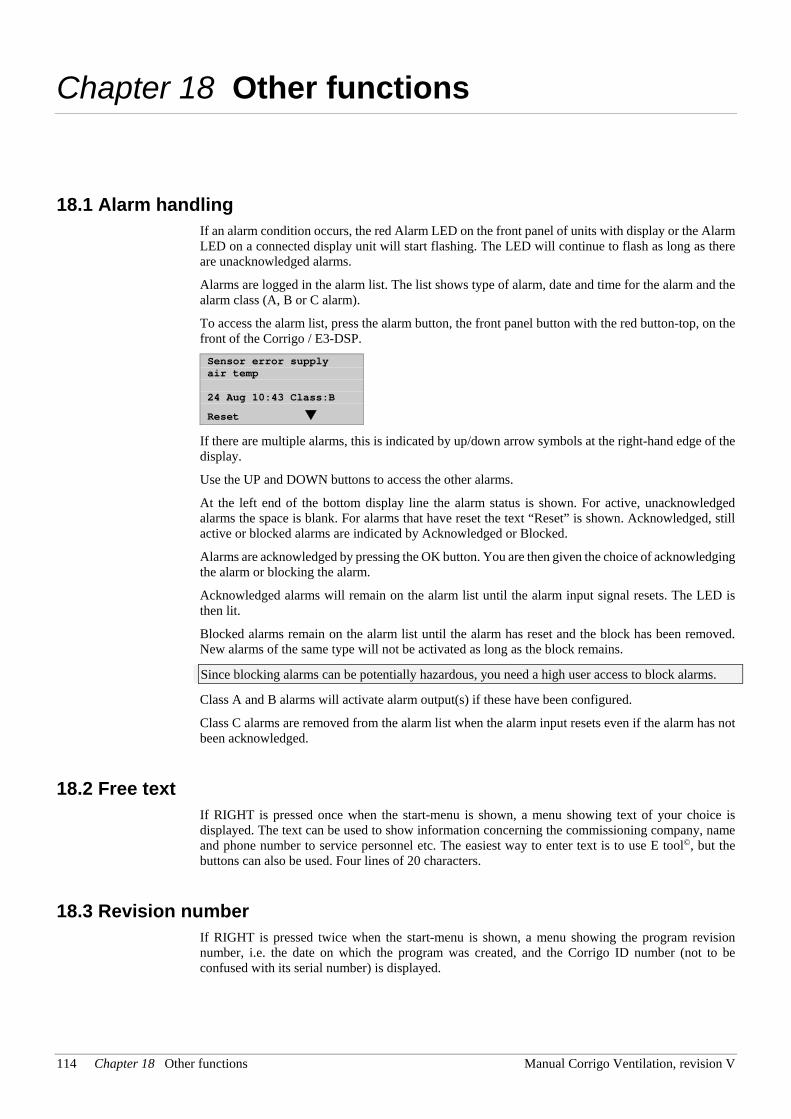
114 Chapter 18 Other functions Manual Corrigo Ventilation, revision V
Chapter 18 Other functions
18.1 Alarm handling If an alarm condition occurs, the red Alarm LED on the front panel of units with display or the Alarm LED on a connected display unit will start flashing. The LED will continue to flash as long as there are unacknowledged alarms.
Alarms are logged in the alarm list. The list shows type of alarm, date and time for the alarm and the alarm class (A, B or C alarm).
To access the alarm list, press the alarm button, the front panel button with the red button-top, on the front of the Corrigo / E3-DSP. Sensor error supply air temp 24 Aug 10:43 Class:B
Reset
If there are multiple alarms, this is indicated by up/down arrow symbols at the right-hand edge of the display.
Use the UP and DOWN buttons to access the other alarms.
At the left end of the bottom display line the alarm status is shown. For active, unacknowledged alarms the space is blank. For alarms that have reset the text “Reset” is shown. Acknowledged, still active or blocked alarms are indicated by Acknowledged or Blocked.
Alarms are acknowledged by pressing the OK button. You are then given the choice of acknowledging the alarm or blocking the alarm.
Acknowledged alarms will remain on the alarm list until the alarm input signal resets. The LED is then lit.
Blocked alarms remain on the alarm list until the alarm has reset and the block has been removed. New alarms of the same type will not be activated as long as the block remains.
Since blocking alarms can be potentially hazardous, you need a high user access to block alarms.
Class A and B alarms will activate alarm output(s) if these have been configured.
Class C alarms are removed from the alarm list when the alarm input resets even if the alarm has not been acknowledged.
18.2 Free text If RIGHT is pressed once when the start-menu is shown, a menu showing text of your choice is displayed. The text can be used to show information concerning the commissioning company, name and phone number to service personnel etc. The easiest way to enter text is to use E tool©, but the buttons can also be used. Four lines of 20 characters.
18.3 Revision number If RIGHT is pressed twice when the start-menu is shown, a menu showing the program revision number, i.e. the date on which the program was created, and the Corrigo ID number (not to be confused with its serial number) is displayed.
Manual Corrigo Ventilation, revision V Chapter 18 Other functions 115
18.4 Language When the start menu is displayed, pressing the RIGHT button three times will display a menu in which the language can be changed.
The different language files are stored in the application memory and are downloaded to the work memory. If a Corrigo via E tool© has been reloaded with a newer program revision than the factory revision, the controller will not allow language files to be downloaded from the application memory. This is because there is a risk that the language files are not compatible with the new revision. Therefore, you are limited to the two languages you have downloaded using E tool©.
18.5 Indication LEDs Status indication can be found in the upper left corner of the master controller. For controllers with display, the alarm indication and change mode LEDs are located in the keypad area.
Status indication
Designation Colour Description
Tx Green Port 1, Transmitting Rx Green Port 1, Receiving LAN (…W models) Yellow/Green Green: Connected to other network
equipment Blinking green: Network traffic Blinking yellow: For identifying
P/B (Power/Battery) Green/Red Power on/Battery error
Controllers with built-in display
Red Alarm indication Yellow Change mode
18.6 Changing the battery This procedure requires knowledge of proper ESD protection; i.e. an earthed wristband must be used!
When the alarm ”Internal Battery” is activated and the battery LED lights up red, the battery for backup of program memory and real-time clock has become too weak. The battery is replaced as described below. A backup capacitor saves the memory and keeps the clock running for at least 10 minutes after the power supply is removed. Therefore, if the battery replacement takes less than 10 minutes, there will be no need to reload the program, and the clock will continue to run normally.
The replacement battery must be of the type CR2032.
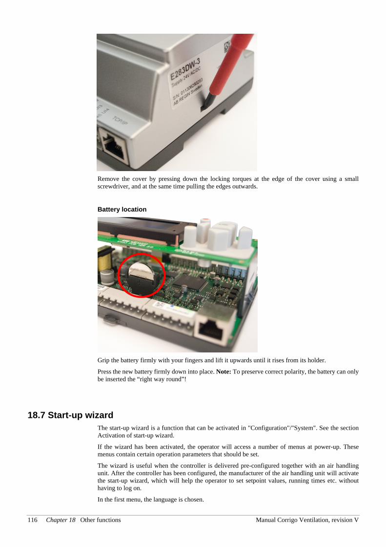
116 Chapter 18 Other functions Manual Corrigo Ventilation, revision V
Remove the cover by pressing down the locking torques at the edge of the cover using a small screwdriver, and at the same time pulling the edges outwards.
Battery location
Grip the battery firmly with your fingers and lift it upwards until it rises from its holder.
Press the new battery firmly down into place. Note: To preserve correct polarity, the battery can only be inserted the “right way round”!
18.7 Start-up wizard The start-up wizard is a function that can be activated in "Configuration"/"System". See the section Activation of start-up wizard.
If the wizard has been activated, the operator will access a number of menus at power-up. These menus contain certain operation parameters that should be set.
The wizard is useful when the controller is delivered pre-configured together with an air handling unit. After the controller has been configured, the manufacturer of the air handling unit will activate the start-up wizard, which will help the operator to set setpoint values, running times etc. without having to log on.
In the first menu, the language is chosen.
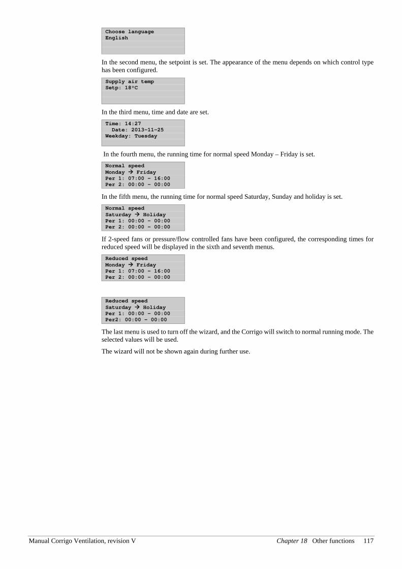
Manual Corrigo Ventilation, revision V Chapter 18 Other functions 117
Choose language English
In the second menu, the setpoint is set. The appearance of the menu depends on which control type has been configured. Supply air temp Setp: 18°C
In the third menu, time and date are set. Time: 14:27 Date: 2013-11-25 Weekday: Tuesday
In the fourth menu, the running time for normal speed Monday – Friday is set. Normal speed Monday Friday Per 1: 07:00 – 16:00 Per 2: 00:00 – 00:00
In the fifth menu, the running time for normal speed Saturday, Sunday and holiday is set. Normal speed Saturday Holiday Per 1: 00:00 – 00:00 Per 2: 00:00 – 00:00
If 2-speed fans or pressure/flow controlled fans have been configured, the corresponding times for reduced speed will be displayed in the sixth and seventh menus. Reduced speed Monday Friday Per 1: 07:00 – 16:00 Per 2: 00:00 – 00:00
Reduced speed Saturday Holiday Per 1: 00:00 – 00:00 Per2: 00:00 – 00:00
The last menu is used to turn off the wizard, and the Corrigo will switch to normal running mode. The selected values will be used.
The wizard will not be shown again during further use.
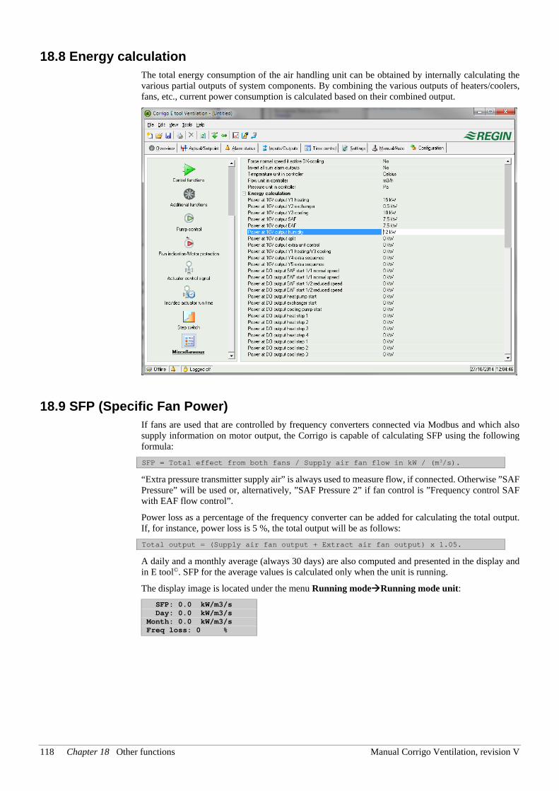
118 Chapter 18 Other functions Manual Corrigo Ventilation, revision V
18.8 Energy calculation The total energy consumption of the air handling unit can be obtained by internally calculating the various partial outputs of system components. By combining the various outputs of heaters/coolers, fans, etc., current power consumption is calculated based on their combined output.
18.9 SFP (Specific Fan Power) If fans are used that are controlled by frequency converters connected via Modbus and which also supply information on motor output, the Corrigo is capable of calculating SFP using the following formula: SFP = Total effect from both fans / Supply air fan flow in kW / (m3/s).
“Extra pressure transmitter supply air” is always used to measure flow, if connected. Otherwise ”SAF Pressure” will be used or, alternatively, ”SAF Pressure 2” if fan control is ”Frequency control SAF with EAF flow control”.
Power loss as a percentage of the frequency converter can be added for calculating the total output. If, for instance, power loss is 5 %, the total output will be as follows: Total output = (Supply air fan output + Extract air fan output) x 1.05.
A daily and a monthly average (always 30 days) are also computed and presented in the display and in E tool©. SFP for the average values is calculated only when the unit is running.
The display image is located under the menu Running modeRunning mode unit: SFP: 0.0 kW/m3/s Day: 0.0 kW/m3/s Month: 0.0 kW/m3/s Freq loss: 0 %
Index
A Access rights, 57 Actuator type, 95 Address, 112 Air control, 66 Alarm
Setting, 98 Alarm events, 60 Alarm list, 99 Alarm settings, 78 Alarms, 51
Alarm delay at startup, 108 Alarm delays, 79 Alarm handling, 113 Alarm limits, 78 Alarm list, 99
Analogue inputs, 17 Analogue outputs, 17 Automatic restart at power-up, 110
B Battery exchanger. See Liquid connected exchanger Blocking of automatic restart at power-up, 53 Blocking of high speed, 107 Buttons, 55
C Cascaded extract air temperature control, 29 Cascaded room temperature control, 29 Change language, 110, 114 Change password, 58 Change-over, 40 Changing the battery, 114 Close-off dampers, 50 Communication, 103 Configuration, 84
Actuator type, 95 Alarm setting, 98 Battery type, 88, 89 Control function, 87 Cooling control, 89 Demand control, 92 Exchanger de-icing, 93 External setpoint, 94 Fan control, 87 Fire dampers, 52, 92 Free cooling, 91 Heat exchangers, 89
Heater type, 88, 89 Humidity control, 93 In- and outputs, 84 Objects, 87 Other parameters, 107 Pump control, 90 Run indication / Motor protection, 94 Running time, 3-position actuators, 95 Step controllers, 96 Support control, 92 System, 110
Control CO2, 78 Control function, 87 Control pressure
Settings, 77 Control signal, analogue outputs. See Cooling recovery, 38, 93 Crosswise interlock, 88
D Damper control, 50 Damper limit, 94 De-icing exchanger, 33 De-icing Liquid connected exchanger. See Heat
exchangers Liquid connected exchanger De-icing plate exchanger" \t, 33 Demand control
Setpoint, 68 Demand controlled ventilation, 47, 92
Mixing dampers, 34 Digital inputs, 17 Digital outputs, 17 Display, 55 DX cooling, 35, 96
Min limit lowering, 90 Setting, 96
DX cooling, blocking, 90
E ELA, 112 Electric heating, 31 Energy calculation, 117 Enthalpy control, 39, 94 Exchanger de-icing, 33, 93
Setpoint, 64 Expansion unit and Modbus master, 104 Expansion units, 82 Extended running, 71 External setpoint, 39, 94 Extra control circuit, 41 Extra flow sensors supply air and extract air, 41
Extra sequence Y4, 89 Extra sequence Y5, 89 Extra temperature sensor, 41
F Fans
Control, 42 Delays, 107 Frequency control EAF with flow control SAF, 46 Frequency control external control signal, 45 Frequency control flow, 44 Frequency control SAF with EAF slave, 46 Frequency control SAF with flow control EAF, 46 Interlock, 88 Manual frequency control, 45 Pressure control, 43 Retardation time, 107 Timer output ½ speed, 71 Timer output 1/1 speed, 70
Fire dampers, 50, 52, 92 Exercising, 50
Flow control Extra compensation curve, 44 Outdoor compensation, 44 Setpoint, 44 Settings, 78
Free cooling, 37, 91 Free text, 113 Frost protection
Frost protection control, 31, 77
H Hardware overview, 13 Heat exchanger
Mixing dampers, 34 Heat exchanger efficiency monitoring, 39, 64 Heat exchangers, 32
Liquid connected exchanger, 33 De-icing, 33
Outdoor temp control of exchangers, 34 Plate exchanger, 32
De-icing, 33 Rotating exchanger, 33 Start condition, 108
Holidays, 72 Hot start, 107 Humidity control, 41, 69, 93
Setpoint, 69 Settings, 78
I In-/Outputs, 60 Indication LEDs, 114 Information screen, 113
Inputs and outputs, 17, 84 Analogue inputs, 17 Analogue outputs, 17 Digital inputs, 17 Digital outputs, 17 Input and output lists, 19 Universal inputs, 17
Intermittent drift, 92
L Language, change, 110, 114 LEDs, 55, 114 Liquid connected exchanger, 33 Log off, 57 Log on, 57 Logoff, 112
M Manual / Auto, 73 Menus, 55 Mixing dampers, 34 Modbus, 103 Model overview, 13 Motor protection / Run indication, 94
N Navigating the menus, 55
O Objects, 87 Other functions, 113 Other parameters, 107 Outdoor temp control of exchanger, 34 Outdoor temp. for control mode change, 109 Outdoor temperature compensated supply air control, 29 Outdoor temperature dependent switching between
supply air temperature control and extract air temperature control, 30
Outdoor temperature dependent switching between supply air temperature control and room temperature control, 29
Outputs. See Override of reduced speed for DX cooling, 90
P Password, 58 PLA, 112 Plate exchanger, 32 Port 2, function, 104
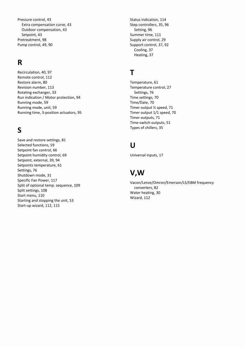
Pressure control, 43 Extra compensation curve, 43 Outdoor compensation, 43 Setpoint, 43
Pretreatment, 98 Pump control, 49, 90
R Recirculation, 40, 97 Remote control, 112 Restore alarm, 80 Revision number, 113 Rotating exchanger, 33 Run indication / Motor protection, 94 Running mode, 59 Running mode, unit, 59 Running time, 3-position actuators, 95
S Save and restore settings, 81 Selected functions, 59 Setpoint fan control, 66 Setpoint humidity control, 69 Setpoint, external, 39, 94 Setpoints temperature, 61 Settings, 76 Shutdown mode, 31 Specific Fan Power, 117 Split of optional temp. sequence, 109 Split settings, 108 Start menu, 110 Starting and stopping the unit, 53 Start-up wizard, 112, 115
Status indication, 114 Step controllers, 35, 96
Setting, 96 Summer time, 111 Supply air control, 29 Support control, 37, 92
Cooling, 37 Heating, 37
T Temperature, 61 Temperature control, 27
Settings, 76 Time settings, 70 Time/Date, 70 Timer output ½ speed, 71 Timer output 1/1 speed, 70 Timer outputs, 71 Time-switch outputs, 51 Types of chillers, 35
U Universal inputs, 17
V,W Vacon/Lenze/Omron/Emerson/LS/EBM frequency
converters, 82 Water heating, 30 Wizard, 112

Appendix
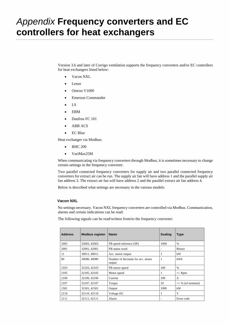
Appendix Frequency converters and EC controllers for heat exchangers
Version 3.6 and later of Corrigo ventilation supports the frequency converters and/or EC controllers for heat exchangers listed below:
• Vacon NXL
• Lenze
• Omron V1000
• Emerson Commander
• LS
• EBM
• Danfoss FC 101
• ABB ACS
• EC Blue
Heat exchanger via Modbus:
• RHC 200
• VariMax25M
When communicating via frequency converters through Modbus, it is sometimes necessary to change certain settings in the frequency converter.
Two parallel connected frequency converters for supply air and two parallel connected frequency converters for extract air can be run. The supply air fan will have address 1 and the parallel supply air fan address 3. The extract air fan will have address 2 and the parallel extract air fan address 4.
Below is described what settings are necessary in the various models:
Vacon NXL No settings necessary. Vacon NXL frequency converters are controlled via Modbus. Communication, alarms and certain indications can be read:
The following signals can be read/written from/to the frequency converter:
Address Modbus register Name Scaling Type
2003 32003, 42003 FB speed reference (SP) 1000 %
2001 32001, 42001 FB status word - Binary
11 30011, 40011 Acc. motor output 1 kW
80 30080, 40080 Number of decimals for acc. motor output
1 kWh
2103 32103, 42103 FB motor speed 100 %
2105 32105, 42105 Motor speed 1 +/- Rpm
2106 32106, 42106 Current 100 A
2107 32107, 42107 Torque 10 +/- % (of nominal)
1501 31501, 41501 Output 1000 kW
2110 32110, 42110 Voltage DC 1 V
2111 32111, 42111 Alarm - Error code
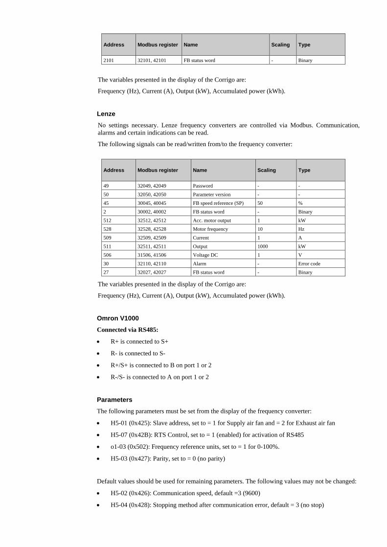
Address Modbus register Name Scaling Type
2101 32101, 42101 FB status word - Binary
The variables presented in the display of the Corrigo are:
Frequency (Hz), Current (A), Output (kW), Accumulated power (kWh).
Lenze No settings necessary. Lenze frequency converters are controlled via Modbus. Communication, alarms and certain indications can be read.
The following signals can be read/written from/to the frequency converter:
Address Modbus register Name Scaling Type
49 32049, 42049 Password - -
50 32050, 42050 Parameter version - -
45 30045, 40045 FB speed reference (SP) 50 %
2 30002, 40002 FB status word - Binary
512 32512, 42512 Acc. motor output 1 kW
528 32528, 42528 Motor frequency 10 Hz
509 32509, 42509 Current 1 A
511 32511, 42511 Output 1000 kW
506 31506, 41506 Voltage DC 1 V
30 32110, 42110 Alarm - Error code
27 32027, 42027 FB status word - Binary
The variables presented in the display of the Corrigo are:
Frequency (Hz), Current (A), Output (kW), Accumulated power (kWh).
Omron V1000 Connected via RS485:
• R+ is connected to S+
• R- is connected to S-
• R+/S+ is connected to B on port 1 or 2
• R-/S- is connected to A on port 1 or 2
Parameters The following parameters must be set from the display of the frequency converter:
• H5-01 (0x425): Slave address, set to = 1 for Supply air fan and = 2 for Exhaust air fan
• H5-07 (0x42B): RTS Control, set to = 1 (enabled) for activation of RS485
• o1-03 (0x502): Frequency reference units, set to = 1 for 0-100%.
• H5-03 (0x427): Parity, set to = 0 (no parity)
Default values should be used for remaining parameters. The following values may not be changed:
• H5-02 (0x426): Communication speed, default =3 (9600)
• H5-04 (0x428): Stopping method after communication error, default = 3 (no stop)
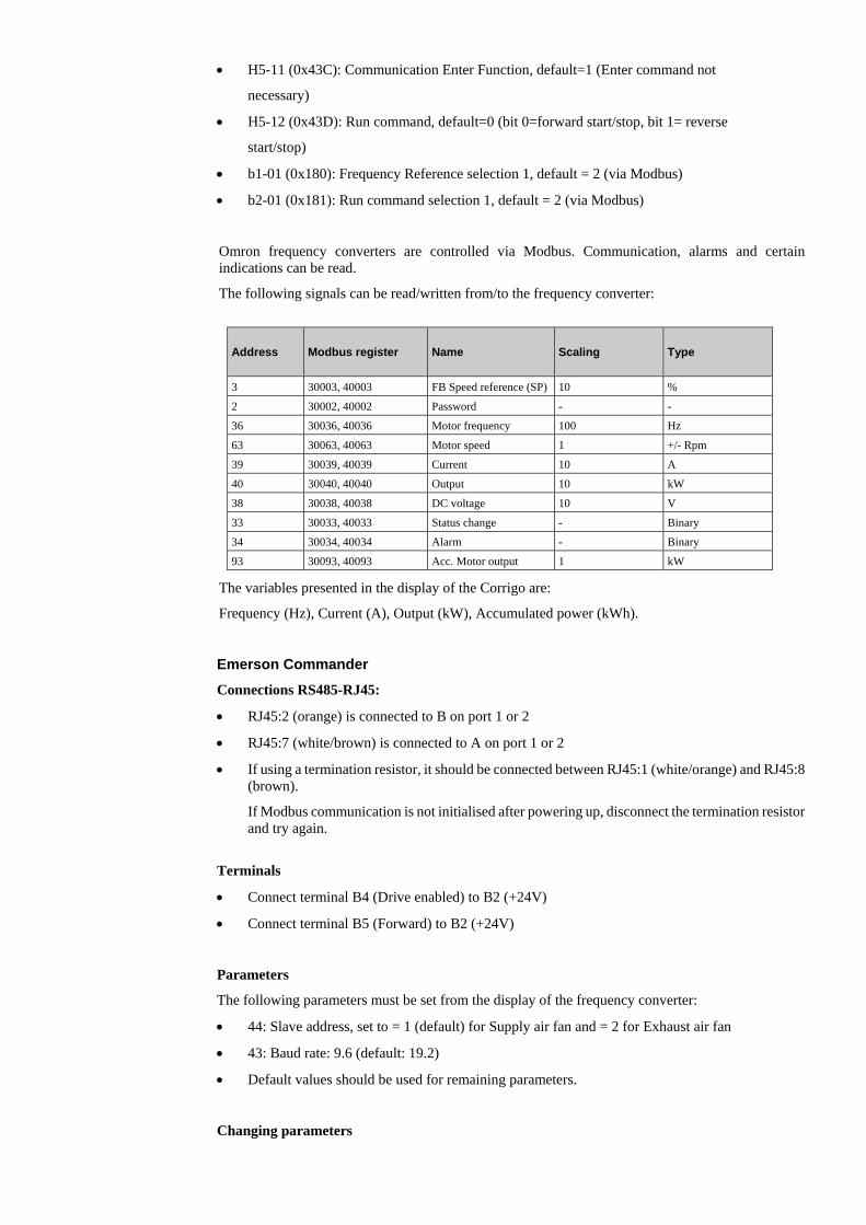
• H5-11 (0x43C): Communication Enter Function, default=1 (Enter command not
necessary)
• H5-12 (0x43D): Run command, default=0 (bit 0=forward start/stop, bit 1= reverse
start/stop)
• b1-01 (0x180): Frequency Reference selection 1, default = 2 (via Modbus)
• b2-01 (0x181): Run command selection 1, default = 2 (via Modbus)
Omron frequency converters are controlled via Modbus. Communication, alarms and certain indications can be read.
The following signals can be read/written from/to the frequency converter:
Address Modbus register Name Scaling Type
3 30003, 40003 FB Speed reference (SP) 10 %
2 30002, 40002 Password - -
36 30036, 40036 Motor frequency 100 Hz
63 30063, 40063 Motor speed 1 +/- Rpm
39 30039, 40039 Current 10 A
40 30040, 40040 Output 10 kW
38 30038, 40038 DC voltage 10 V
33 30033, 40033 Status change - Binary
34 30034, 40034 Alarm - Binary
93 30093, 40093 Acc. Motor output 1 kW
The variables presented in the display of the Corrigo are:
Frequency (Hz), Current (A), Output (kW), Accumulated power (kWh). Emerson Commander Connections RS485-RJ45:
• RJ45:2 (orange) is connected to B on port 1 or 2
• RJ45:7 (white/brown) is connected to A on port 1 or 2
• If using a termination resistor, it should be connected between RJ45:1 (white/orange) and RJ45:8 (brown).
If Modbus communication is not initialised after powering up, disconnect the termination resistor and try again.
Terminals
• Connect terminal B4 (Drive enabled) to B2 (+24V)
• Connect terminal B5 (Forward) to B2 (+24V)
Parameters
The following parameters must be set from the display of the frequency converter:
• 44: Slave address, set to = 1 (default) for Supply air fan and = 2 for Exhaust air fan
• 43: Baud rate: 9.6 (default: 19.2)
• Default values should be used for remaining parameters.
Changing parameters
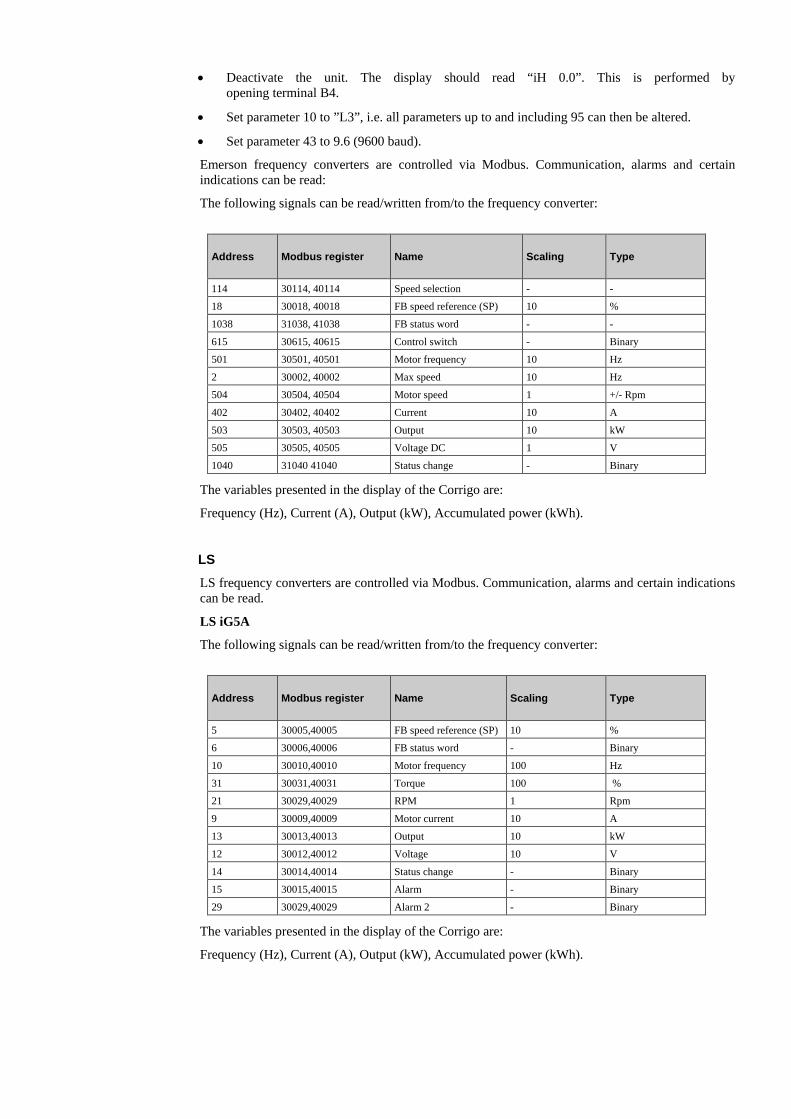
• Deactivate the unit. The display should read “iH 0.0”. This is performed by opening terminal B4.
• Set parameter 10 to ”L3”, i.e. all parameters up to and including 95 can then be altered.
• Set parameter 43 to 9.6 (9600 baud).
Emerson frequency converters are controlled via Modbus. Communication, alarms and certain indications can be read:
The following signals can be read/written from/to the frequency converter:
Address Modbus register Name Scaling Type
114 30114, 40114 Speed selection - -
18 30018, 40018 FB speed reference (SP) 10 %
1038 31038, 41038 FB status word - -
615 30615, 40615 Control switch - Binary
501 30501, 40501 Motor frequency 10 Hz
2 30002, 40002 Max speed 10 Hz
504 30504, 40504 Motor speed 1 +/- Rpm
402 30402, 40402 Current 10 A
503 30503, 40503 Output 10 kW
505 30505, 40505 Voltage DC 1 V
1040 31040 41040 Status change - Binary
The variables presented in the display of the Corrigo are:
Frequency (Hz), Current (A), Output (kW), Accumulated power (kWh). LS LS frequency converters are controlled via Modbus. Communication, alarms and certain indications can be read.
LS iG5A
The following signals can be read/written from/to the frequency converter:
Address Modbus register Name Scaling Type
5 30005,40005 FB speed reference (SP) 10 %
6 30006,40006 FB status word - Binary
10 30010,40010 Motor frequency 100 Hz
31 30031,40031 Torque 100 %
21 30029,40029 RPM 1 Rpm
9 30009,40009 Motor current 10 A
13 30013,40013 Output 10 kW
12 30012,40012 Voltage 10 V
14 30014,40014 Status change - Binary
15 30015,40015 Alarm - Binary
29 30029,40029 Alarm 2 - Binary
The variables presented in the display of the Corrigo are:
Frequency (Hz), Current (A), Output (kW), Accumulated power (kWh).
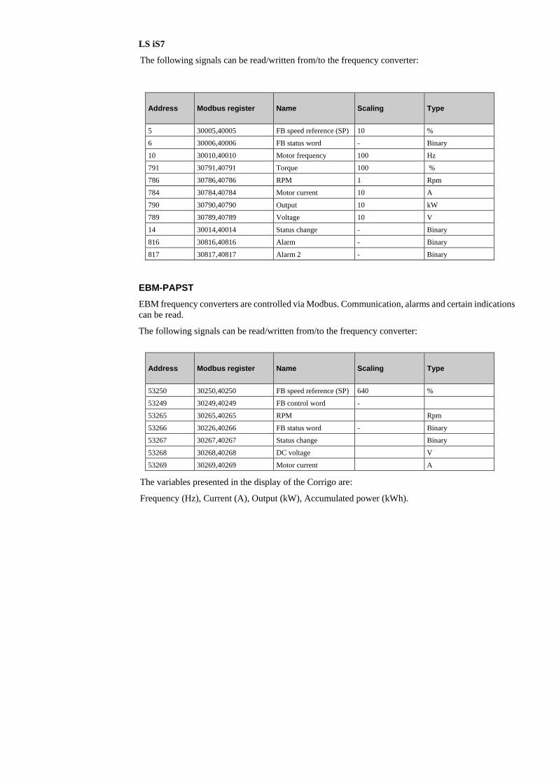
LS iS7
The following signals can be read/written from/to the frequency converter:
Address Modbus register Name Scaling Type
5 30005,40005 FB speed reference (SP) 10 %
6 30006,40006 FB status word - Binary
10 30010,40010 Motor frequency 100 Hz
791 30791,40791 Torque 100 %
786 30786,40786 RPM 1 Rpm
784 30784,40784 Motor current 10 A
790 30790,40790 Output 10 kW
789 30789,40789 Voltage 10 V
14 30014,40014 Status change - Binary
816 30816,40816 Alarm - Binary
817 30817,40817 Alarm 2 - Binary
EBM-PAPST EBM frequency converters are controlled via Modbus. Communication, alarms and certain indications can be read.
The following signals can be read/written from/to the frequency converter:
Address Modbus register Name Scaling Type
53250 30250,40250 FB speed reference (SP) 640 %
53249 30249,40249 FB control word -
53265 30265,40265 RPM Rpm
53266 30226,40266 FB status word - Binary
53267 30267,40267 Status change Binary
53268 30268,40268 DC voltage V
53269 30269,40269 Motor current A
The variables presented in the display of the Corrigo are:
Frequency (Hz), Current (A), Output (kW), Accumulated power (kWh).
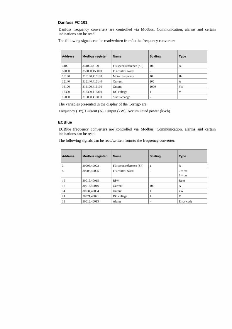
Danfoss FC 101 Danfoss frequency converters are controlled via Modbus. Communication, alarms and certain indications can be read.
The following signals can be read/written from/to the frequency converter:
Address Modbus register Name Scaling Type
3100 33100,43100 FB speed reference (SP) 100 %
50000 350000,450000 FB control word -
16130 316130,416130 Motor frequency 10 Hz
16140 316140,416140 Current 100 A
16100 316100,416100 Output 1000 kW
16300 316300,416300 DC voltage 1 V
16030 316030,416030 Status change -
The variables presented in the display of the Corrigo are:
Frequency (Hz), Current (A), Output (kW), Accumulated power (kWh).
ECBlue ECBlue frequency converters are controlled via Modbus. Communication, alarms and certain indications can be read.
The following signals can be read/written from/to the frequency converter:
Address Modbus register Name Scaling Type
3 30003,40003 FB speed reference (SP) 1 %
5 30005,40005 FB control word - 0 = off 3 = on
15 30015,40015 RPM Rpm
16 30016,40016 Current 100 A
34 30034,40034 Output 1 kW
21 30021,40021 DC voltage 1 V
13 30013,40013 Alarm - Error code
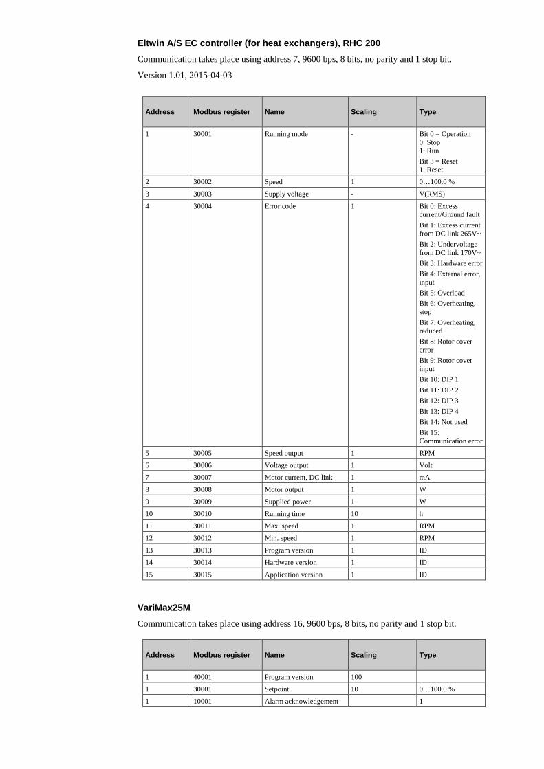
Eltwin A/S EC controller (for heat exchangers), RHC 200 Communication takes place using address 7, 9600 bps, 8 bits, no parity and 1 stop bit.
Version 1.01, 2015-04-03
Address Modbus register Name Scaling Type
1 30001 Running mode - Bit 0 = Operation 0: Stop 1: Run Bit 3 = Reset 1: Reset
2 30002 Speed 1 0…100.0 %
3 30003 Supply voltage - V(RMS)
4 30004 Error code 1 Bit 0: Excess current/Ground fault Bit 1: Excess current from DC link 265V~ Bit 2: Undervoltage from DC link 170V~ Bit 3: Hardware error Bit 4: External error, input Bit 5: Overload Bit 6: Overheating, stop Bit 7: Overheating, reduced Bit 8: Rotor cover error Bit 9: Rotor cover input Bit 10: DIP 1 Bit 11: DIP 2 Bit 12: DIP 3 Bit 13: DIP 4 Bit 14: Not used Bit 15: Communication error
5 30005 Speed output 1 RPM
6 30006 Voltage output 1 Volt
7 30007 Motor current, DC link 1 mA
8 30008 Motor output 1 W
9 30009 Supplied power 1 W
10 30010 Running time 10 h
11 30011 Max. speed 1 RPM
12 30012 Min. speed 1 RPM
13 30013 Program version 1 ID
14 30014 Hardware version 1 ID
15 30015 Application version 1 ID
VariMax25M Communication takes place using address 16, 9600 bps, 8 bits, no parity and 1 stop bit.
Address Modbus register Name Scaling Type
1 40001 Program version 100
1 30001 Setpoint 10 0…100.0 %
1 10001 Alarm acknowledgement 1