Embed Size (px)
Citation preview

Bridgelux® Gen 7 V13 Array Product Data Sheet DS101
BXRE-27x2000 | 30x2000 | 35x2000 | 40x2000 | 50x2001 | 57x2001 | 65x2001

Introduction
The V Series™ LED Array products deliver high quality light in a compact and cost-effective solid-state lighting package.
These Chip-on-Board (CoB) arrays can be efficiently driven at twice the nominal drive current, enabling design flexibility
not previously possible. This high flux density light source is designed to support a wide range of high quality, low cost
directional luminaires and replacement lamps for commercial and residential applications.
The V13 LED Array is available in a variety of electrical, CCT and CRI combinations providing substantial design flexibility
and energy efficiencies.
Lighting system designs incorporating these LED Arrays deliver increased system level efficacy and longer service life.
Typical applications include, but are not limited to, replacement lamps, task, accent, spot, track, down light, wide area,
security, and wall pack.
V S
erie
sFeatures
• Efficacy of 155 lm/W typical
• Compact high flux density light source
• Uniform high quality illumination
• Minimum 70, 80 and 90 CRI options
• Streamlined thermal path
• ENERGY STAR® / ANSI compliant color binning structure with 3 SDCM and 4 SDCM options
• More energy efficient than incandescent, halogen and fluorescent lamps
• Low voltage DC operation
• Instant light with unlimited dimming
Benefits
• Enhanced optical control
• Clean white light without pixilation
• High quality true color reproduction
• Significantly reduced thermal resistance and increased operating temperatures
• Uniform consistent white light
• Lower operating costs
• Easy to use with daylight and motion detectors to enable increased energy savings
• Reduced maintenance costs
• Environmentally friendly, no disposal issue
Pending Standards and Classifications: ENEC

Contents
Product Feature Map 2
Product Nomenclature 2
Product Selection Guide 3
Performance at Commonly Used Drive Currents 5
Electrical Characteristics 9
Absolute Maximum Ratings 10
Performance Curves 11
Typical Radiation Pattern 15
Typical Color Spectrum 16
Mechanical Dimensions 17
Color Binning Information 18
Packaging and Labeling 19
Design Resources 21
Precautions 21
Disclaimers 21
About Bridgelux 22
1
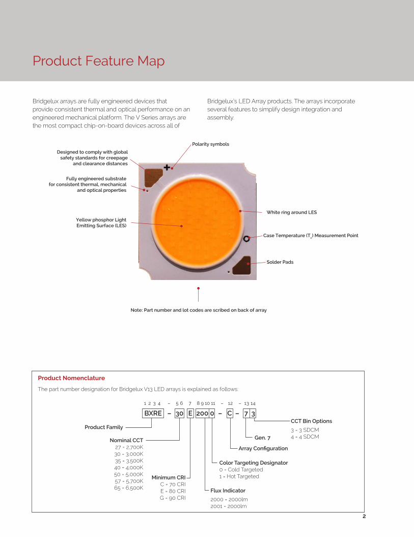
Product Feature Map
Bridgelux arrays are fully engineered devices that provide consistent thermal and optical performance on an engineered mechanical platform. The V Series arrays are the most compact chip-on-board devices across all of
Product Nomenclature
The part number designation for Bridgelux V13 LED arrays is explained as follows:
Bridgelux’s LED Array products. The arrays incorporate several features to simplify design integration and assembly.
2
1 2 3 4 – 5 6 7 8 9 10 11 – 12 – 13 14
Product FamilyCCT Bin Options
3 = 3 SDCM4 = 4 SDCM
Flux Indicator
2000 = 2000lm2001 = 2000lm
Minimum CRIC = 70 CRIE = 80 CRIG = 90 CRI
Array Configuration
Nominal CCT27 = 2,700K30 = 3,000K35 = 3,500K40 = 4,000K50 = 5,000K57 = 5,700K65 = 6,500K
BXRE – 30 E 200 0 – C – 7 3
Fully engineered substrate for consistent thermal, mechanical
and optical properties
Yellow phosphor Light Emitting Surface (LES)
Note: Part number and lot codes are scribed on back of array
Polarity symbols
Solder Pads
White ring around LES
Case Temperature (Tc) Measurement Point
Designed to comply with global safety standards for creepage
and clearance distances
Color Targeting Designator0 = Cold Targeted1 = Hot Targeted
Gen. 7

Product Selection Guide
The following product configurations are available:
Table 1: Selection Guide, Pulsed Measurement Data (Tj = Tc = 25°C)
Part NumberNominal CCT1
(K)CRI2
Nominal Drive Current3
(mA)
Typical Pulsed Flux4,5,6
Tc = 25ºC(lm)
Minimum Pulsed Flux6,7
Tc = 25ºC(lm)
Typical Vf (V)
Typical Power
(W)
Typical Efficacy (lm/W)
BXRE-27E2000-B-7X 2700 80 450 2323 2189 34.8 15.6 149
BXRE-27E2000-C-7X 2700 80 630 3251 2991 34.8 21.9 149
BXRE-27G2000-B-7X 2700 90 450 1936 1824 34.8 15.6 124
BXRE-27G2000-C-7X 2700 90 630 2709 2493 34.8 21.9 124
BXRE-30E2000-B-7X 3000 80 450 2420 2280 34.8 15.6 155
BXRE-30E2000-C-7X 3000 80 630 3387 3116 34.8 21.9 155
BXRE-30G2000-B-7X 3000 90 450 2008 1860 34.8 15.6 128
BXRE-30G2000-C-7X 3000 90 630 2811 2586 34.8 21.9 128
BXRE-35E2000-B-7X 3500 80 450 2492 2348 34.8 15.6 159
BXRE-35E2000-C-7X 3500 80 630 3488 3209 34.8 21.9 159
BXRE-35G2000-B-7X 3500 90 450 2081 1961 34.8 15.6 133
BXRE-35G2000-C-7X 3500 90 630 2913 2680 34.8 21.9 133
BXRE-40E2000-B-7X 4000 80 450 2516 2350 34.8 15.6 161
BXRE-40E2000-C-7X 4000 80 630 3522 3240 34.8 21.9 161
BXRE-40G2000-B-7X 4000 90 450 2153 2029 34.8 15.6 138
BXRE-40G2000-C-7X 4000 90 630 3014 2773 34.8 21.9 138
BXRE-50C2001-B-74 5000 70 450 2758 2599 34.8 15.6 176
BXRE-50C2001-C-74 5000 70 630 3861 3552 34.8 21.9 176
BXRE-50E2001-B-74 5000 80 450 2593 2443 34.8 15.6 166
BXRE-50E2001-C-74 5000 80 630 3629 3339 34.8 21.9 166
BXRE-50G2001-B-74 5000 90 450 2207 2079 34.8 15.6 141
BXRE-50G2001-C-74 5000 90 630 3089 2842 34.8 21.9 141
BXRE-57C2001-B-74 5700 70 450 2662 2508 34.8 15.6 170
BXRE-57C2001-C-74 5700 70 630 3725 3427 34.8 21.9 170
BXRE-57E2001-B-74 5700 80 450 2637 2485 34.8 15.6 169
BXRE-57E2001-C-74 5700 80 630 3692 3396 34.8 21.9 169
BXRE-65C2001-B-74 6500 70 450 2710 2554 34.8 15.6 173
BXRE-65C2001-C-74 6500 70 630 3793 3490 34.8 21.9 173
BXRE-65E2001-B-74 6500 80 450 2686 2531 34.8 15.6 172
BXRE-65E2001-C-74 6500 80 630 3759 3459 34.8 21.9 172
Notes for Tables 1:
1. Nominal CCT as defined by ANSI C78.377-2011. Prodcuts with CCTs 5000K-6500K are hot targetd to 85°C.
2. CRI values are minimums. Minimum R9 value for 80 CRI products is 0, the minimum R9 values for 90 CRI products is 50.
3. Drive current is referred to as nominal drive current.
4. Products tested under pulsed condition (10ms pulse width) at nominal test current where Tj (junction temperature) = Tc (case temperature) = 25°C.
5. Typical performance values are provided as a reference only and are not a guarantee of performance.
6. Bridgelux maintains a ±7% tolerance on flux measurements.
7. Minimum flux values at the nominal test current are guaranteed by 100% test.
3

Product Selection Guide
Table 2: Selection Guide, Stabilized DC Performance (Tc = 85°C) 4,5
Notes for Tables 2:
1. Nominal CCT as defined by ANSI C78.377-2011. Prodcuts with a CCT of 5000K-6500K are hot targetd to 85°C.
2. CRI values are minimums. Minimum R9 value for 80 CRI products is 0, the minimum R9 values for 90 CRI products is 50.
3. Drive current is referred to as nominal drive current.
4. Typical stabilized DC performance values are provided as reference only and are not a guarantee of performance.
5. Typical performance is estimated based on operation under DC (direct current) with LED array mounted onto a heat sink with thermal interface material and the case temperature maintained at 85°C. Based on Bridgelux test setup, values may vary depending on the thermal design of the luminaire and/or the exposed environment to which the product is subjected.
6. Minimum flux values at elevated temperatures are provided for reference only and are not guaranteed by 100% production testing. Based on Bridgelux test setup, values may vary depending on the thermal design of the luminaire and/or the exposed environment to which the product is subjected.
Part NumberNominal CCT1
(K)CRI2
Nominal Drive Current3
(mA)
Typical DC Flux4,5
Tc = 85ºC(lm)
Minimum DC Flux6
Tc = 85ºC(lm)
Typical Vf (V)
Typical Power
(W)
Typical Efficacy (lm/W)
BXRE-27E2000-B-7X 2700 80 450 2090 1970 33.9 15.3 137
BXRE-27E2000-C-7X 2700 80 630 2926 2692 33.9 21.4 137
BXRE-27G2000-B-7X 2700 90 450 1742 1642 33.9 15.3 114
BXRE-27G2000-C-7X 2700 90 630 2438 2243 33.9 21.4 114
BXRE-30E2000-B-7X 3000 80 450 2178 2052 33.9 15.3 143
BXRE-30E2000-C-7X 3000 80 630 3048 2804 33.9 21.4 143
BXRE-30G2000-B-7X 3000 90 450 1807 1674 33.9 15.3 118
BXRE-30G2000-C-7X 3000 90 630 2530 2328 33.9 21.4 118
BXRE-35E2000-B-7X 3500 80 450 2243 2114 33.9 15.3 147
BXRE-35E2000-C-7X 3500 80 630 3140 2888 33.9 21.4 147
BXRE-35G2000-B-7X 3500 90 450 1873 1765 33.9 15.3 123
BXRE-35G2000-C-7X 3500 90 630 2621 2412 33.9 21.4 123
BXRE-40E2000-B-7X 4000 80 450 2265 2115 33.9 15.3 148
BXRE-40E2000-C-7X 4000 80 630 3170 2916 33.9 21.4 148
BXRE-40G2000-B-7X 4000 90 450 1938 1826 33.9 15.3 127
BXRE-40G2000-C-7X 4000 90 630 2713 2496 33.9 21.4 127
BXRE-50C2001-B-74 5000 70 450 2482 2339 33.9 15.3 163
BXRE-50C2001-C-74 5000 70 630 3475 3197 33.9 21.4 163
BXRE-50E2001-B-74 5000 80 450 2334 2199 33.9 15.3 153
BXRE-50E2001-C-74 5000 80 630 3266 3005 33.9 21.4 153
BXRE-50G2001-B-74 5000 90 450 1986 1871 33.9 15.3 130
BXRE-50G2001-C-74 5000 90 630 2780 2557 33.9 21.4 130
BXRE-57C2001-B-74 5700 70 450 2395 2257 33.9 15.3 157
BXRE-57C2001-C-74 5700 70 630 3353 3085 33.9 21.4 157
BXRE-57E2001-B-74 5700 80 450 2374 2237 33.9 15.3 156
BXRE-57E2001-C-74 5700 80 630 3322 3057 33.9 21.4 156
BXRE-65C2001-B-74 6500 70 450 2439 2298 33.9 15.3 160
BXRE-65C2001-C-74 6500 70 630 3414 3141 33.9 21.4 160
BXRE-65E2001-B-74 6500 80 450 2417 2278 33.9 15.3 158
BXRE-65E2001-C-74 6500 80 630 3383 3113 33.9 21.4 158
4

Performance at Commonly Used Drive Currents
V Series LED arrays are tested to the specifications shown using the nominal drive currents in Table 1. V Series may
also be driven at other drive currents dependent on specific application design requirements. The performance at any
drive current can be derived from the current vs. voltage characteristics shown in Figures 1 & 2 and the flux vs. current
characteristics shown in Figures 3 & 4. The performance at commonly used drive currents is summarized in Table 3.
5
Table 3: Product Performance at Commonly Used Drive Currents
Part Number CRIDrive
Current1
(mA)
Typical Vf Tc = 25ºC
(V)
Typical Power
Tc = 25ºC(W)
Typical Flux2
Tc = 25ºC(lm)
Typical DC Flux3 Tc = 85ºC
(lm)
Typical Efficacy Tc = 25ºC(lm/W)
BXRE-27E2000-B-7X 80
113 32.3 3.6 637 588 175225 33.2 7.5 1228 1127 165450 34.8 15.6 2323 2090 149675 36.0 24.3 3361 3050 138900 37.2 33.5 4286 3871 128
BXRE-27E2000-C-7X 80
158 32.3 5.1 884 837 174315 33.2 10.4 1706 1608 163630 34.8 21.9 3251 2926 149945 36.1 34.1 4672 4369 1371260 37.3 47.0 5961 5556 127
BXRE-27G2000-B-7X 90
113 32.3 3.6 530 490 146225 33.2 7.5 1024 939 137450 34.8 15.6 1936 1742 124675 36.0 24.3 2801 2542 115900 37.2 33.5 3571 3226 107
BXRE-27G2000-C-7X 90
158 32.3 5.1 737 698 145315 33.2 10.4 1422 1340 136630 34.8 21.9 2709 2438 124945 36.1 34.1 3893 3641 1141260 37.3 47.0 4968 4630 106
BXRE-30E2000-B-7X 80
113 32.3 3.6 663 612 182225 33.2 7.5 1280 1174 171450 34.8 15.6 2420 2178 155675 36.0 24.3 3501 3177 144900 37.2 33.5 4464 4032 133
BXRE-30E2000-C-7X 80
158 32.3 5.1 921 872 181315 33.2 10.4 1777 1675 170630 34.8 21.9 3387 3048 155945 36.1 34.1 4867 4551 1431260 37.3 47.0 6210 5788 132
Notes for Table 3:1. Alternate drive currents in Table 3 are provided for reference only and are not a guarantee of performance.2. Bridgelux maintains a ± 7% tolerance on flux measurements.3. Typical stabilized DC performance values are provided as reference only and are not a guarantee of performance.
6
Performance at Commonly Used Drive Currents
Notes for Table 3:1. Alternate drive currents in Table 3 are provided for reference only and are not a guarantee of performance.2. Bridgelux maintains a ± 7% tolerance on flux measurements.3. Typical stabilized DC performance values are provided as reference only and are not a guarantee of performance.
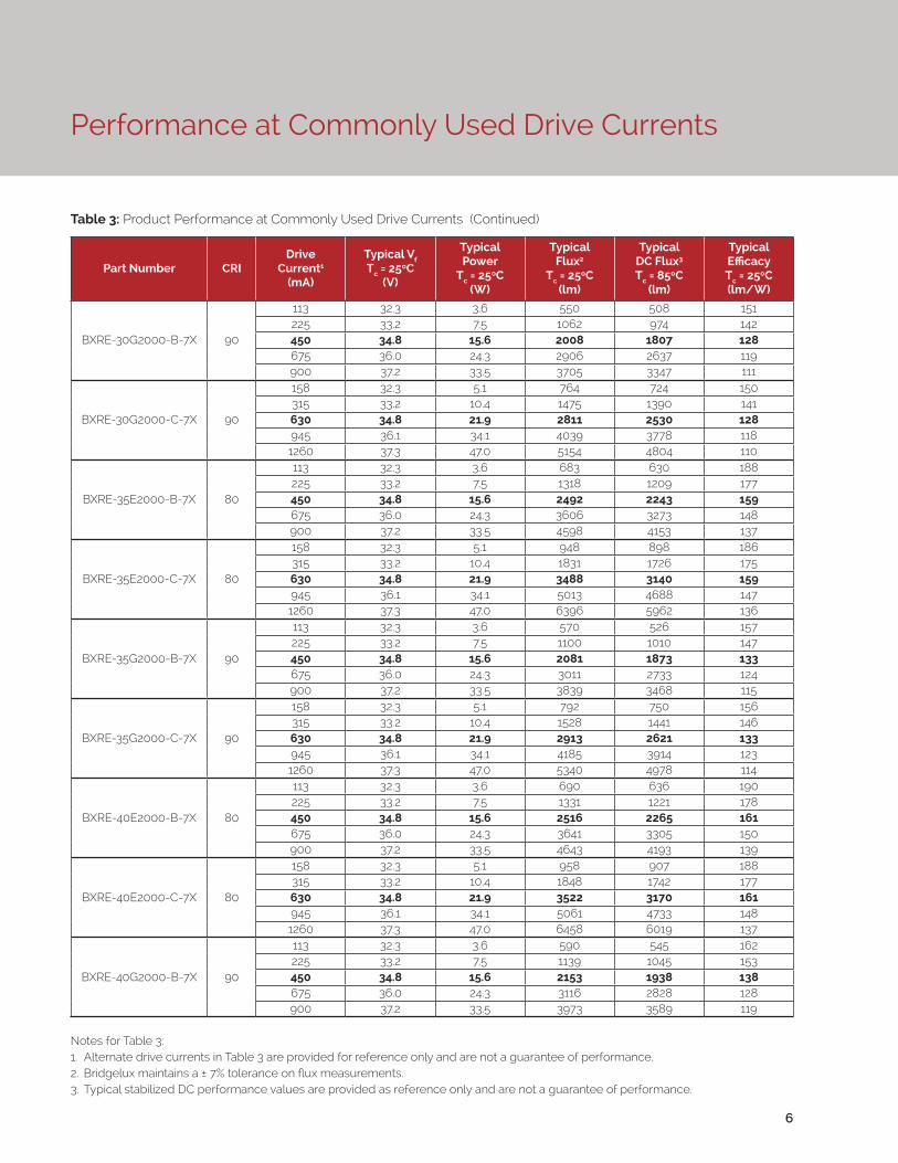
Table 3: Product Performance at Commonly Used Drive Currents (Continued)
Part Number CRIDrive
Current1
(mA)
Typical Vf Tc = 25ºC
(V)
Typical Power
Tc = 25ºC(W)
Typical Flux2
Tc = 25ºC(lm)
Typical DC Flux3 Tc = 85ºC
(lm)
Typical Efficacy Tc = 25ºC(lm/W)
BXRE-30G2000-B-7X 90
113 32.3 3.6 550 508 151225 33.2 7.5 1062 974 142450 34.8 15.6 2008 1807 128675 36.0 24.3 2906 2637 119900 37.2 33.5 3705 3347 111
BXRE-30G2000-C-7X 90
158 32.3 5.1 764 724 150315 33.2 10.4 1475 1390 141630 34.8 21.9 2811 2530 128945 36.1 34.1 4039 3778 1181260 37.3 47.0 5154 4804 110
BXRE-35E2000-B-7X 80
113 32.3 3.6 683 630 188225 33.2 7.5 1318 1209 177450 34.8 15.6 2492 2243 159675 36.0 24.3 3606 3273 148900 37.2 33.5 4598 4153 137
BXRE-35E2000-C-7X 80
158 32.3 5.1 948 898 186315 33.2 10.4 1831 1726 175630 34.8 21.9 3488 3140 159945 36.1 34.1 5013 4688 1471260 37.3 47.0 6396 5962 136
BXRE-35G2000-B-7X 90
113 32.3 3.6 570 526 157225 33.2 7.5 1100 1010 147450 34.8 15.6 2081 1873 133675 36.0 24.3 3011 2733 124900 37.2 33.5 3839 3468 115
BXRE-35G2000-C-7X 90
158 32.3 5.1 792 750 156315 33.2 10.4 1528 1441 146630 34.8 21.9 2913 2621 133945 36.1 34.1 4185 3914 1231260 37.3 47.0 5340 4978 114
BXRE-40E2000-B-7X 80
113 32.3 3.6 690 636 190225 33.2 7.5 1331 1221 178450 34.8 15.6 2516 2265 161675 36.0 24.3 3641 3305 150900 37.2 33.5 4643 4193 139
BXRE-40E2000-C-7X 80
158 32.3 5.1 958 907 188315 33.2 10.4 1848 1742 177630 34.8 21.9 3522 3170 161945 36.1 34.1 5061 4733 1481260 37.3 47.0 6458 6019 137
BXRE-40G2000-B-7X 90
113 32.3 3.6 590 545 162225 33.2 7.5 1139 1045 153450 34.8 15.6 2153 1938 138675 36.0 24.3 3116 2828 128900 37.2 33.5 3973 3589 119

7
Notes for Table 3:1. Alternate drive currents in Table 3 are provided for reference only and are not a guarantee of performance.2. Bridgelux maintains a ± 7% tolerance on flux measurements.3. Typical stabilized DC performance values are provided as reference only and are not a guarantee of performance.
Table 3: Product Performance at Commonly Used Drive Currents (Continued)
Part Number CRIDrive
Current1
(mA)
Typical Vf Tc = 25ºC
(V)
Typical Power
Tc = 25ºC(W)
Typical Flux2
Tc = 25ºC(lm)
Typical DC Flux3 Tc = 85ºC
(lm)
Typical Efficacy Tc = 25ºC(lm/W)
BXRE-40G2000-C-7X 90
158 32.3 5.1 820 776 161315 33.2 10.4 1582 1491 151630 34.8 21.9 3014 2713 138945 36.1 34.1 4331 4051 1271260 37.3 47.0 5527 5151 118
BXRE-50C2001-B-74 70
113 32.3 3.6 756 698 208225 33.2 7.5 1459 1338 195450 34.8 15.6 2758 2482 176675 36.0 24.3 3991 3622 164900 37.2 33.5 5089 4597 152
BXRE-50C2001-C-74 70
158 32.3 5.1 1050 994 206315 33.2 10.4 2026 1910 194630 34.8 21.9 3861 3475 176945 36.1 34.1 5548 5189 1631260 37.3 47.0 7079 6598 151
BXRE-50E2001-B-74 80
113 32.3 3.6 711 656 195225 33.2 7.5 1371 1258 184450 34.8 15.6 2593 2334 166675 36.0 24.3 3751 3405 154900 37.2 33.5 4784 4321 143
BXRE-50E2001-C-74 80
158 32.3 5.1 987 935 194315 33.2 10.4 1904 1795 182630 34.8 21.9 3629 3266 166945 36.1 34.1 5215 4877 1531260 37.3 47.0 6655 6202 142
BXRE-50G2001-B-74 90
113 32.3 3.6 605 558 166225 33.2 7.5 1167 1071 156450 34.8 15.6 2207 1986 141675 36.0 24.3 3193 2898 131900 37.2 33.5 4071 3677 122
BXRE-50G2001-C-74 90
158 32.3 5.1 840 795 165315 33.2 10.4 1621 1528 155630 34.8 21.9 3089 2780 141945 36.1 34.1 4438 4151 1301260 37.3 47.0 5663 5279 120
BXRE-57C2001-B-74 70
113 32.3 3.6 729 673 201225 33.2 7.5 1408 1291 189450 34.8 15.6 2662 2395 170675 36.0 24.3 3851 3495 158900 37.2 33.5 4911 4435 147
BXRE-57C2001-C-74 70
158 32.3 5.1 1013 959 199315 33.2 10.4 1955 1843 187630 34.8 21.9 3725 3353 170945 36.1 34.1 5353 5007 1571260 37.3 47.0 6831 6367 145
Performance at Commonly Used Drive Currents

8
Performance at Commonly Used Drive Currents
Notes for Table 3:1. Alternate drive currents in Table 3 are provided for reference only and are not a guarantee of performance.2. Bridgelux maintains a ± 7% tolerance on flux measurements.3. Typical stabilized DC performance values are provided as reference only and are not a guarantee of performance.
Table 3: Product Performance at Commonly Used Drive Currents (Continued)
Part Number CRIDrive
Current1
(mA)
Typical Vf Tc = 25ºC
(V)
Typical Power
Tc = 25ºC(W)
Typical Flux2
Tc = 25ºC(lm)
Typical DC Flux3 Tc = 85ºC
(lm)
Typical Efficacy Tc = 25ºC(lm/W)
BXRE-57E2001-B-74 80
113 32.3 3.6 723 667 199225 33.2 7.5 1395 1280 187450 34.8 15.6 2637 2374 169675 36.0 24.3 3816 3463 157900 37.2 33.5 4866 4395 145
BXRE-57E2001-C-74 80
158 32.3 5.1 1004 951 197315 33.2 10.4 1937 1826 185630 34.8 21.9 3692 3322 169945 36.1 34.1 5305 4961 1551260 37.3 47.0 6769 6309 144
BXRE-65C2001-B-74 70
113 32.3 3.6 743 685 204225 33.2 7.5 1433 1315 192450 34.8 15.6 2710 2439 173675 36.0 24.3 3921 3559 161900 37.2 33.5 5000 4516 149
BXRE-65C2001-C-74 70
158 32.3 5.1 1031 977 203315 33.2 10.4 1990 1876 191630 34.8 21.9 3793 3414 173945 36.1 34.1 5451 5098 1601260 37.3 47.0 6955 6482 148
BXRE-65E2001-B-74 80
113 32.3 3.6 736 679 202225 33.2 7.5 1420 1303 190450 34.8 15.6 2686 2417 172675 36.0 24.3 3886 3527 160900 37.2 33.5 4955 4476 148
BXRE-65E2001-C-74 80
158 32.3 5.1 1022 968 201315 33.2 10.4 1973 1860 189630 34.8 21.9 3759 3383 172945 36.1 34.1 5402 5052 1581260 37.3 47.0 6893 6425 147

Electrical Characteristics
Notes for Table 4:
1. Parts are tested in pulsed conditions, Tc = 25°C. Pulse width is 10ms.
2. Voltage minimum and maximum are provided for reference only and are not a guarantee of performance.
3. Bridgelux maintains a tester tolerance of ± O.10V on forward voltage measurements.
4. Typical coefficient of forward voltage tolerance is ± O.1mV for nominal current.
5. Thermal resistance values are based from test data of a 3000K 80 CRI product.
6. Thermal resistance value was calculated using total electrical input power; optical power was not subtracted from input power. The thermal interface material used during testing is not included in the thermal resistance value.
7. Vf min hot and max cold values are provided as reference only and are not guaranteed by test. These values are provided to aid in driver design and selection over the operating range of the product.
Table 4: Electrical Characteristics
9
Part NumberDrive Current
(mA)
Forward VoltagePulsed, Tc = 25ºC (V) 1, 2, 3 Typical
Coefficient of Forward
Voltage4 ∆Vf/∆Tc
(mV/ºC)
Typical Thermal
Resistance Junction to Case5,6
Rj-c (ºC/W)
Driver Selection Voltages7
(V)
Minimum Typical MaximumVf Min.
Hot Tc = 105ºC
(V)
Vf Max. Cold
Tc = -40ºC (V)
BXRE-xxx200x-B-7x450 32.1 34.8 37.4 -14.2 0.28 31.0 38.3
900 34.4 37.2 40.0 -14.2 0.34 33.3 40.9
BXRE-xxx200x-C-7x630 32.1 34.8 37.4 -14.2 0.20 31.0 38.3
1260 34.5 37.3 40.1 -14.2 0.24 33.4 41.0

10
Absolute Maximum Ratings
Parameter Maximum Rating
LED Junction Temperature (Tj) 125°C
Storage Temperature -40°C to +105°C
Operating Case Temperature1 (Tc) 105°C
Soldering Temperature2 350°C or lower for a maximum of 10 seconds
BXRE-xxx200x-B-7x BXRE-xxx200x-C-7x
Maximum Drive Current3 900mA 1260mA
Maximum Peak Pulsed Drive Current4 1286mA 1800mA
Maximum Reverse Voltage5 -60V -60V
Table 5: Maximum Ratings
Notes for Table 5:
1. For IEC 62717 requirement, please consult your Bridgelux sales representative.
2. Refer to Bridgelux Application Note AN41: Handling and Assembly of Bridgelux V Series LED Arrays
3. Arrays may be driven at higher currents however lumen maintenance may be reduced.
4. Bridgelux recommends a maximum duty cycle of 10% and pulse width of 20 ms when operating LED Arrays at maximum peak pulsed current specified. Maximum peak pulsed currents indicate values where LED Arrays can be driven without catastrophic failures.
5. Light emitting diodes are not designed to be driven in reverse voltage and will not produce light under this condition. Maximum rating provided for reference only.

Performance Curves
Figure 1: V13B Drive Current vs. Voltage (Tj = Tc = 25°C)
Figure 2: V13C Drive Current vs. Voltage (Tj = Tc = 25°C)
11
0
100
200
300
400
500
600
700
800
900
1000
32 33 34 35 36 37 38
Forw
ard
Cur
rent
(mA)
Forward Voltage (V)
100
250
400
550
700
850
1000
1150
1300
32 33 34 35 36 37 38
Forw
ard
Cur
rent
(mA)
Forward Voltage (V)

Performance Curves
Figure 3: V13B Typical Relative Flux vs. Current( Tj = Tc = 25°C)
12
Figure 4: V13C Typical Relative Flux vs. Current( Tj = Tc = 25°C)
Note for Figures 3 & 4:
1. Bridgelux does not recommend driving high power LEDs at low currents. Doing so may produce unpredictable results. Pulse width modulation (PWM) is recommended for dimming effects.
0%
20%
40%
60%
80%
100%
120%
140%
160%
180%
200%
0 100 200 300 400 500 600 700 800 900 1000
Rela
tive
Lum
inou
s Flu
x
Forward Current (mA)
0%
20%
40%
60%
80%
100%
120%
140%
160%
180%
200%
100 250 400 550 700 850 1000 1150 1300
Rela
tive
Lum
inou
s Flu
x
Forward Current (mA)

Figure 5: Typical DC Flux vs. Case Temperature
Figure 6: Typical DC ccy Shift vs. Case Temperature
13
Performance Curves
Notes for Figures 5 & 6:
1. Characteristics shown for warm white based on 3000K and 80 CRI.2. Characteristics shown for neutral white based on 4000K and 80 CRI.3. Characteristics shown for cool white based on 5000K and 70 CRI.4. For other color SKUs, the shift in color will vary. Please contact your Bridgelux sales representative for more information.
82%
85%
88%
91%
94%
97%
100%
103%
0 25 50 75 100 125
Rela
tive
Lum
inou
s Flu
x
Case Temperature (°C)
Warm WhiteNeutral WhiteCool White25°C Pulsed
-0.015
-0.012
-0.009
-0.006
-0.003
0.000
0.0030 25 50 75 100 125
ccy
Shift
Case Temperature (°C)
Warm WhiteNeutral WhiteCool White25°C Pulsed

Performance Curves
Figure 7: Typical DC ccx Shift vs. Case Temperature
14
Notes for Figure 7:
1. Characteristics shown for warm white based on 3000K and 80 CRI.
2. Characteristics shown for neutral white based on 4000K and 80 CRI.
3. Characteristics shown for cool white based on 5000K and 70 CRI.
4. For other color SKUs, the shift in color will vary. Please contact your Bridgelux sales representative for more information.
-0.012
-0.010
-0.008
-0.006
-0.004
-0.002
0.0000 25 50 75 100 125
ccx
Shift
Case Temperature (°C)
Warm WhiteNeutral WhiteCool White25°C Pulsed
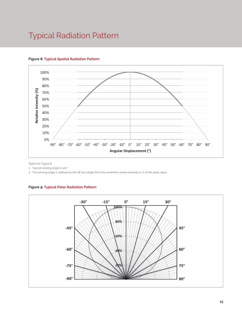
Typical Radiation Pattern
Figure 8: Typical Spatial Radiation Pattern
Figure 9: Typical Polar Radiation Pattern
15
Notes for Figure 8:
1. Typical viewing angle is 120⁰.
2. The viewing angle is defined as the off axis angle from the centerline where intensity is ½ of the peak value.

Typical Color Spectrum
Figure 10: Typical Color Spectrum
16
Notes for Figure 10:
1. Color spectra measured at nominal current for Tj = Tc = 25°C.
2. Color spectra shown is 3000K and 80 CRI.
3. Color spectra shown is 4000K and 80 CRI.
4. Color spectra shown is 5000K and 70 CRI.
4. Color spectra shown is 6500K and 70 CRI.
0%
10%
20%
30%
40%
50%
60%
70%
80%
90%
100%
110%
400 450 500 550 600 650 700 750 800
Rela
tive
Spec
tral
Pow
er D
istr
ibut
ion
Wavelength (nm)
3000K4000K5000K6500K

Mechanical Dimensions
Figure 11: V13 LED Array
17
Notes for Figure 11:
1. Drawings are not to scale.
2. Drawing dimensions are in millimeters.
3. Unless otherwise specified, tolerances are ±0.1mm.
4. Mounting holes (2X) are for M2.5 screws.
5. Bridgelux recommends two tapped holes for mounting screws with 31.4 ± 0.10mm center-to-center spacing.
6. Screws with flat shoulders (pan, dome, button, round, truss, mushroom) provide optimal torque control. Do NOT use flat, countersink, or raised head screws.
7. Solder pads and connector port are labeled “+” and “-“ to denote positive and negative, respectively.
8. It is not necessary to provide electrical connections to both the solder pads and the connector port. Either set may be used depending on application specific design requirements.
9. Refer to Application Notes AN30 and AN31 for product handling, mounting and heat sink recommendations.
10. The optical center of the LED Array is nominally defined by the mechanical center of the array to a tolerance of ± 0.2mm.
11. Bridgelux maintains a flatness of 0.10mm across the mounting surface of the array.

Color Binning Information
Figure 12: Graph of Warm and Neutral White Test Bins in xy Color Space
Figure 13: Graph of Cool White Test Bins in xy Color Space
Bin Code 2700K 3000K 3500K 4000K
ANSI Bin(for reference only)
(2580K - 2870K) (2870K - 3220K) (3220K - 3710K) (3710K - 4260K)
23 (3 SDCM) (2651K - 2794K) (2968K - 3136K) (3369K - 3586K) (3851K - 4130K)
22 (2 SDCM) (2674K - 2769K) (2995K - 3107K) (3404K - 3548K) (3895K - 4081K)
Center Point (x,y) (0.4578, 0.4101) (0.4338, 0.403) (0.4073, 0.3917) (0.3818, 0.3797)
Table 6: Warm and Neutral White xy Bin Coordinates and Associated Typical CCT
Bin Code 5000K 5700K 6500K
ANSI Bin (for reference only) (4745K - 5311K) (5312K - 6022K) (6022K - 7042K)
4 (4 SDCM) (4801K - 5282K) (5829K - 5481K) (6270K - 6765K)
Center Point (x,y) (0.3447, 0.3553) (0.3287, 0.3417) (0.3123, 0.3282)
Table 7: Cool White xy Bin Coordinates and Associated Typical CCT (product is hot targeted to Tc = 85°C)
Note: Pulsed Test Conditions, Tc = 25°C
Note: Pulsed Test Conditions, Tc = 25°C
18
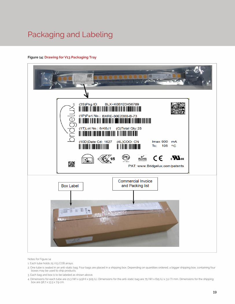
Packaging and Labeling
19
Figure 14: Drawing for V13 Packaging Tray
Notes for Figure 14:
1. Each tube holds 25 V13 COB arrays.
2. One tube is sealed in an anti-static bag. Four bags are placed in a shipping box. Depending on quantities ordered, a bigger shipping box, containing four boxes may be used to ship products.
3. Each bag and box is to be labeled as shown above.
4. Dimensions for each tube are 21.3 (W) x 9.5(H) x 505 (L). Dimensions for the anti-static bag are 75 (W) x 615 (L) x 3.1 (T) mm. Dimensions for the shipping box are 58.7 x 13.3 x 7.9 cm.

Packaging and Labeling
20
Figure 15: Gen. 7 Product Labeling
Bridgelux COB arrays have laser markings on the back side of the substrate to help with product identification. In
addition to the product identification markings, Bridgelux COB arrays also contain markings for internal Bridgelux
manufacturing use only. The image below shows which markings are for customer use and which ones are for
Bridgelux internal use only. The Bridgelux internal manufacturing markings are subject to change without notice,
however these will not impact the form, function or performance of the COB array.
Customer Use- 2D Barcode Scannable barcode provides product part number and other Bridgelux internal production information.
Customer Use- Product part number

Design Resources
Disclaimers
Precautions
Application Notes
Bridgelux has developed a comprehensive set of application notes and design resources to assist customers in successfully designing with the V Series product family of LED array products. For all available application notes visit www.bridgelux.com.
Optical Source Models
Optical source models and ray set files are available for all Bridgelux products. For a list of available formats, visit www.bridgelux.com.
MINOR PRODUCT CHANGE POLICY
The rigorous qualification testing on products offered by Bridgelux provides performance assurance. Slight cosmetic changes that do not affect form, fit, or function may occur as Bridgelux continues product optimization.
CAUTION: CHEMICAL EXPOSURE HAZARD
Exposure to some chemicals commonly used in luminaire manufacturing and assembly can cause damage to the LED array. Please consult Bridgelux Application Note AN31 for additional information.
CAUTION: EYE SAFETY
Eye safety classification for the use of Bridgelux V Series LED arrays is in accordance with specification IEC/TR 62778: Application of IEC 62471 for the assessment of blue light hazard to light sources and luminaires. V Series LED arrays are classified as Risk Group 2 (Moderate Risk) when operated at or below 2.5 times the nominal drive current. The Ethr value is 889.79 lux per IEC/TR 62778. Please use appropriate precautions. Under many operating conditions the V Series LED arrays are classified as Risk Group 1, for more information please contact your Bridgelux sales representative. It is important that employees working with LEDs are trained to use them safely.
3D CAD Models
Three dimensional CAD models depicting the product outline of all Bridgelux V Series LED arrays are available in both IGS and STEP formats. Please contact your Bridgelux sales representative for assistance.
LM80
LM80 testing is ongoing. Please contact your Bridgelux sales representative for more information.
21
CAUTION
CONTACT WITH LIGHT EMITTING SURFACE (LES)
Avoid any contact with the LES. Do not touch the LES of the LED array or apply stress to the LES (yellow phosphor resin area). Contact may cause damage to the LED array.
Optics and reflectors must not be mounted in contact with the LES (yellow phosphor resin area). Use the mechanical features of the LED array housing, edges and/or mounting holes to locate and secure optical devices as needed.
STANDARD TEST CONDITIONS
Unless otherwise stated, array testing is performed at the nominal drive current.
CAUTION: RISK OF BURN
Do not touch the V Series LED array during operation. Allow the array to cool for a sufficient period of time before handling. The V Series LED array may reach elevated temperatures such that could burn skin when touched

22
About Bridgelux: We Build Light That Transforms
© 2016 Bridgelux, Inc. All rights reserved 2016. Product specifications are subject to change without notice. Bridgelux, the Bridgelux stylized logo design and Vero are registered trademarks, and Decor Series is a trademark of Bridgelux, Inc. All other trademarks are the property of their respective owners.
Bridgelux Gen 7 V13 Array Series Product Data Sheet DS101 Rev. A (06/2016)
101 Portola Avenue
Livermore, CA 94551
Tel (925) 583-8400
Fax (925) 583-8410
www.bridgelux.com
At Bridgelux, we help companies, industries and people experience the power and possibility of light. Since 2002, we’ve designed LED solutions that are high performing, energy efficient, cost effective and easy to integrate. Our focus is on light’s impact on human behavior, deliver-ing products that create better environments, experiences and returns—both experiential and financial. And our patented technology drives new platforms for commercial and industrial luminaires.
For more information about the company, please visit bridgelux.comtwitter.com/Bridgeluxfacebook.com/BridgeluxWeChat ID: BridgeluxInChina