Embed Size (px)
Citation preview
Bridgelux® EB Series™ SlimProduct Data Sheet DS170

Introduction
EB Slim linear modules are designed for use in premium indoor applications where high efficacy is required. The new
generation uses the high-efficacy SMDs to achieve over 170lm/W, which enables designers and fixture manufacturers
to meet DLC Standard requirements. They are designed for linear troffers, pendants and other luminaires in indoor
commercial applications.
Available in 340 mm, 590 mm, and 1190 mm lengths, the modules can be connected end-to-end thereby providing
flexibility in designing luminaires. The slim width of the module enables easy integration into space constrained
luminaires. These modules are easily mountable and offer reusable poke-in connectors.
EB
Se
ries™
Features
• High efficacy up to 170 lm/W (nominal)
• Available in 80 CRI
• Available in color temperatures from 3000K to 5000K
• Wide lumen range with 2.4x overdrive capability
• Long lifetime (L80, B50 > 50,000 hours)
Benefits
• Achieve over 170 lm/W by under-driving
• Heat-sinking may not be required at low drive currents
• Reliable use at elevated currents for greater design flexibility
• Easy installation using mounting holes and poke-in connectors
1
Contents
Product Feature Map 2
Product Nomenclature 2
Product Selection Guide 3
Electrical Characteristics 4
Absolute Maximum Ratings 5
Performance Curves 6
Typical Radiation Pattern 8
Typical Color Spectrum 9
Mechanical Dimensions 10
Color Binning Information 12
Packaging and Labeling 13
Design Resources 14
Precautions 14
Disclaimers 14
About Bridgelux 15
2
Product Feature Map
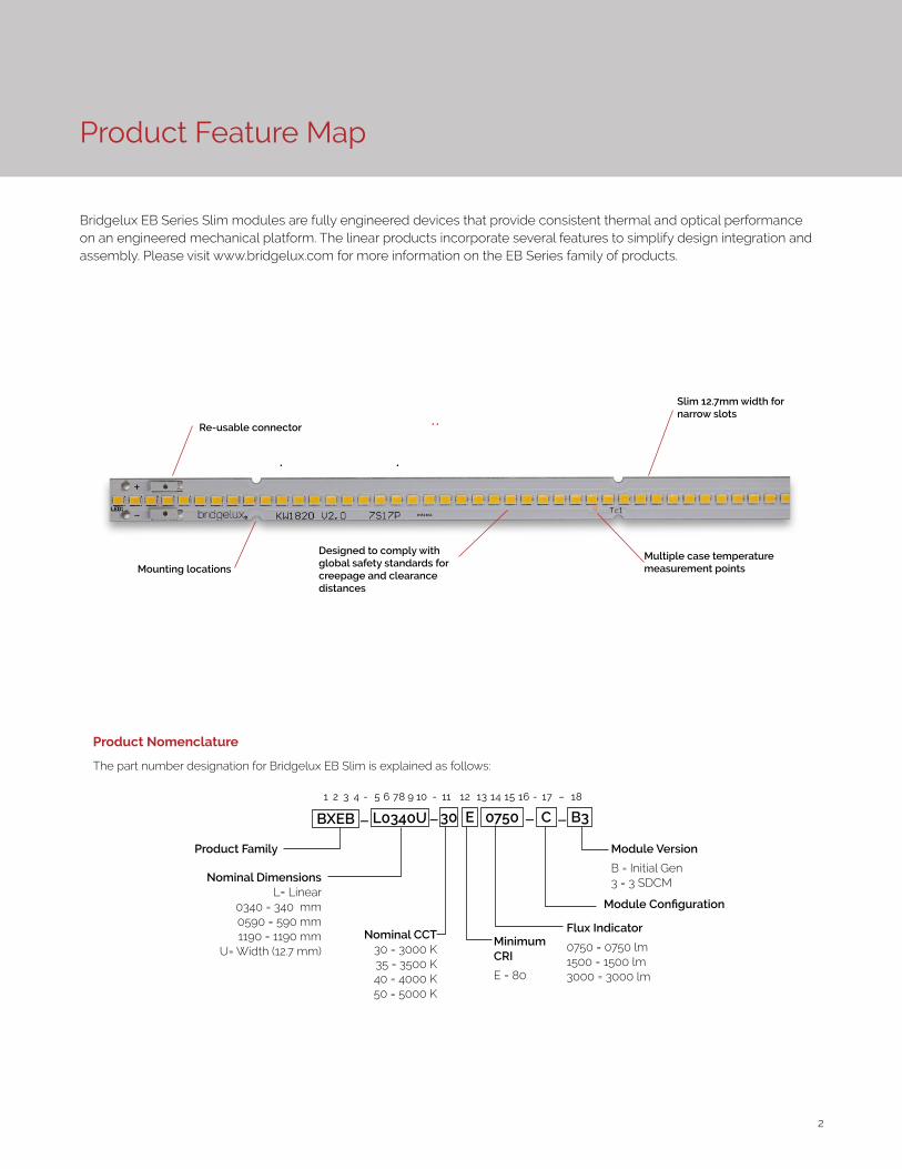
Bridgelux EB Series Slim modules are fully engineered devices that provide consistent thermal and optical performance on an engineered mechanical platform. The linear products incorporate several features to simplify design integration and assembly. Please visit www.bridgelux.com for more information on the EB Series family of products.
Product Nomenclature
The part number designation for Bridgelux EB Slim is explained as follows:
Nominal CCT30 = 3000 K35 = 3500 K40 = 4000 K50 = 5000 K
1 2 3 4 - 5 6 7 8 9 10 - 11 12 13 14 15 16 - 17 – 18
BXEB L0340U 0750 B3C
Product Family Module Version
B = Initial Gen3 = 3 SDCM
Flux Indicator
0750 = 0750 lm1500 = 1500 lm3000 = 3000 lm
Module Configuration
Nominal DimensionsL= Linear
0340 = 340 mm0590 = 590 mm 1190 = 1190 mm
U= Width (12.7 mm)
30 E
Minimum CRI
E = 80
– – – –
Mounting locations
Re-usable connector
Designed to comply with global safety standards for creepage and clearance distances
Multiple case temperature measurement points
Slim 12.7mm width for narrow slots
3
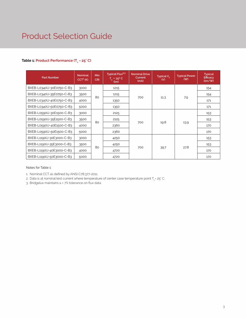
Product Selection Guide
Table 1: Product Performance (Tc = 25° C)
Part NumberNominal
CCT1 (K)
Min
CRI
Typical Flux2,3
Tc = 25º C(lm)
Nominal Drive Current
(mA)
Typical Vf (V)
Typical Power(W)
Typical Efficacy (lm/W)
BXEB-L0340U-30E0750-C-B3 3000
80
1215
700 11.3 7.9
154
BXEB-L0340U-35E0750-C-B3 3500 1215 154
BXEB-L0340U-40E0750-C-B3 4000 1350 171
BXEB-L0340U-50E0750-C-B3 5000 1350 171
BXEB-L0590U-30E1500-C-B3 3000
80
2125
700 19.8 13.9
153
BXEB-L0590U-35E1500-C-B3 3500 2125 153
BXEB-L0590U-40E1500-C-B3 4000 2360 170
BXEB-L0590U-50E1500-C-B3 5000 2360 170
BXEB-L1190U-30E3000-C-B3 3000
80
4250
700 39.7 27.8
153
BXEB-L1190U-35E3000-C-B3 3500 4250 153
BXEB-L1190U-40E3000-C-B3 4000 4720 170
BXEB-L1190U-50E3000-C-B3 5000 4720 170
Notes for Table 1:
1. Nominal CCT as defined by ANSI C78.377-2011. 2. Data is at nominal test current where temperature of center case temperature point Tc= 25° C. 3. Bridgelux maintains a ± 7% tolerance on flux data.
4
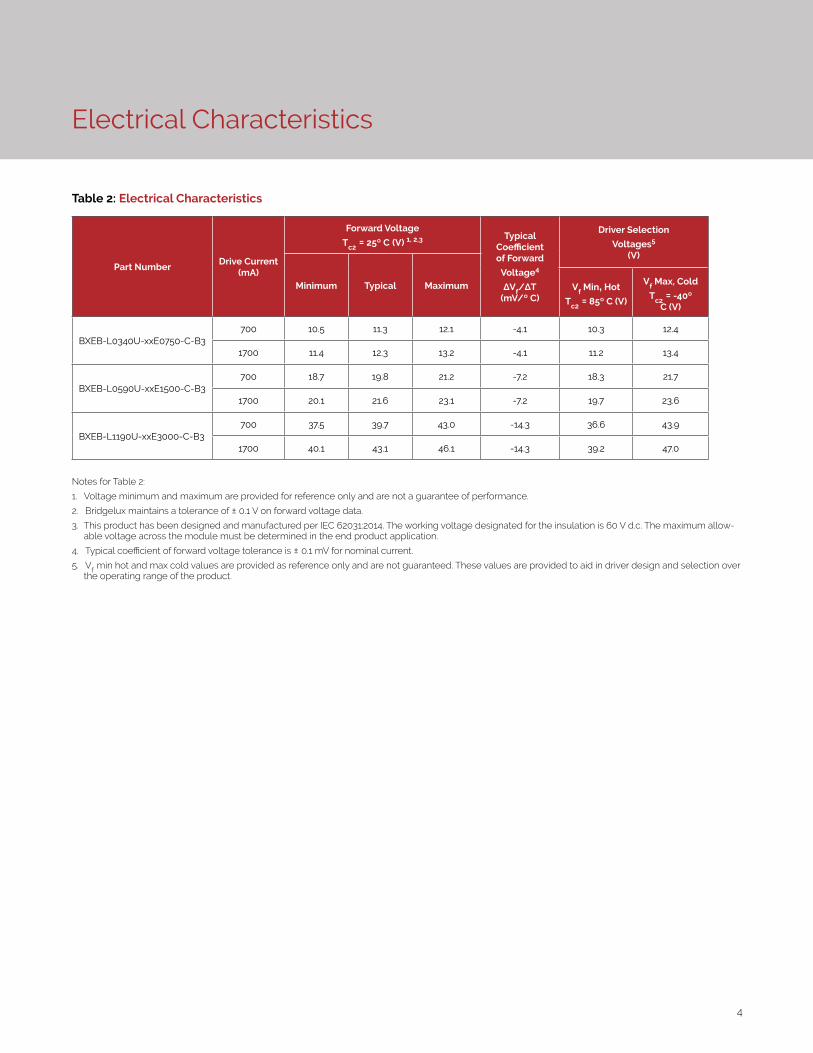
Electrical Characteristics
Table 2: Electrical Characteristics
Part NumberDrive Current
(mA)
Forward Voltage
Tc2 = 25º C (V) 1, 2,3 Typical Coefficient of Forward
Voltage4 ∆Vf/∆T
(mV/º C)
Driver Selection
Voltages5
(V)
Minimum Typical Maximum Vf Min, Hot
Tc2 = 85º C (V)
Vf Max, Cold
Tc2 = -40º C (V)
BXEB-L0340U-xxE0750-C-B3700 10.5 11.3 12.1 -4.1 10.3 12.4
1700 11.4 12.3 13.2 -4.1 11.2 13.4
BXEB-L0590U-xxE1500-C-B3700 18.7 19.8 21.2 -7.2 18.3 21.7
1700 20.1 21.6 23.1 -7.2 19.7 23.6
BXEB-L1190U-xxE3000-C-B3700 37.5 39.7 43.0 -14.3 36.6 43.9
1700 40.1 43.1 46.1 -14.3 39.2 47.0
Notes for Table 2:
1. Voltage minimum and maximum are provided for reference only and are not a guarantee of performance.
2. Bridgelux maintains a tolerance of ± 0.1 V on forward voltage data.
3. This product has been designed and manufactured per IEC 62031:2014. The working voltage designated for the insulation is 60 V d.c. The maximum allow-able voltage across the module must be determined in the end product application.
4. Typical coefficient of forward voltage tolerance is ± 0.1 mV for nominal current.
5. Vf min hot and max cold values are provided as reference only and are not guaranteed. These values are provided to aid in driver design and selection over the operating range of the product.
5
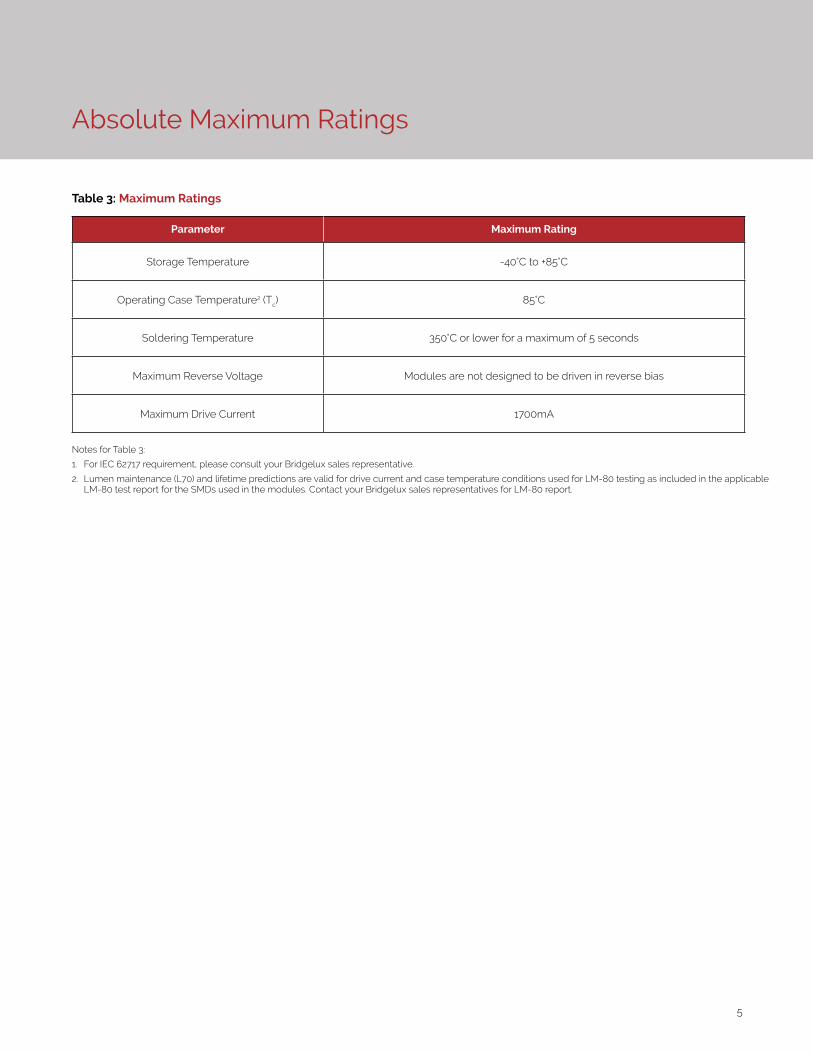
Absolute Maximum Ratings
Table 3: Maximum Ratings
Parameter Maximum Rating
Storage Temperature -40°C to +85°C
Operating Case Temperature2 (Tc) 85°C
Soldering Temperature 350°C or lower for a maximum of 5 seconds
Maximum Reverse Voltage Modules are not designed to be driven in reverse bias
Maximum Drive Current 1700mA
Notes for Table 3:
1. For IEC 62717 requirement, please consult your Bridgelux sales representative.
2. Lumen maintenance (L70) and lifetime predictions are valid for drive current and case temperature conditions used for LM-80 testing as included in the applicable LM-80 test report for the SMDs used in the modules. Contact your Bridgelux sales representatives for LM-80 report.
6
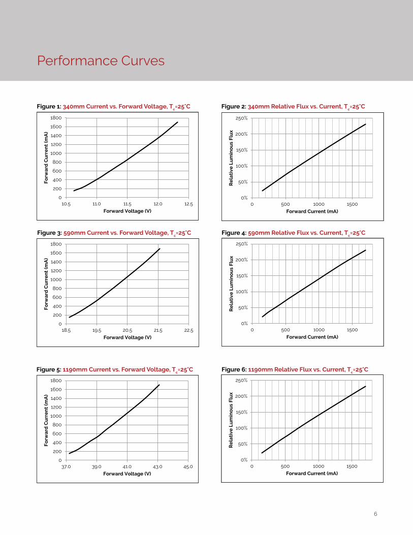
Performance Curves
Figure 1: 340mm Current vs. Forward Voltage, Tc=25°C Figure 2: 340mm Relative Flux vs. Current, Tc=25°C
0%
50%
100%
150%
200%
250%
0 500 1000 1500
Re
lati
ve L
um
ino
us
Flu
x
Forward Current (mA)
0
200
400
600
800
1000
1200
1400
1600
1800
10.5 11.0 11.5 12.0 12.5
Fo
rwa
rd C
urr
en
t (m
A)
Forward Voltage (V)
0%
50%
100%
150%
200%
250%
0 500 1000 1500
Re
lati
ve L
um
ino
us
Flu
x
Forward Current (mA)
0
200
400
600
800
1000
1200
1400
1600
1800
18.5 19.5 20.5 21.5 22.5
Fo
rwa
rd C
urr
en
t (m
A)
Forward Voltage (V)
Figure 3: 590mm Current vs. Forward Voltage, Tc=25°C Figure 4: 590mm Relative Flux vs. Current, Tc=25°C
0%
50%
100%
150%
200%
250%
0 500 1000 1500
Re
lati
ve L
um
ino
us
Flu
x
Forward Current (mA)
0
200
400
600
800
1000
1200
1400
1600
1800
37.0 39.0 41.0 43.0 45.0
Fo
rwa
rd C
urr
en
t (m
A)
Forward Voltage (V)
Figure 5: 1190mm Current vs. Forward Voltage, Tc=25°C Figure 6: 1190mm Relative Flux vs. Current, Tc=25°C
7
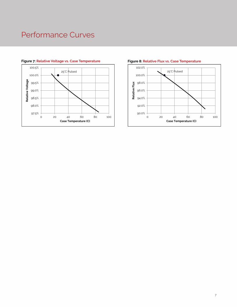
Performance Curves
97.5%
98.0%
98.5%
99.0%
99.5%
100.0%
100.5%
0 20 40 60 80 100
Re
lati
ve V
olt
ag
e
Case Temperature (C)
25°C Pulsed
Figure 7: Relative Voltage vs. Case Temperature
90.0%
92.0%
94.0%
96.0%
98.0%
100.0%
102.0%
0 20 40 60 80 100
Re
lati
ve F
lux
Case Temperature (C)
25°C Pulsed
Figure 8: Relative Flux vs. Case Temperature
8
Typical Radiation Pattern
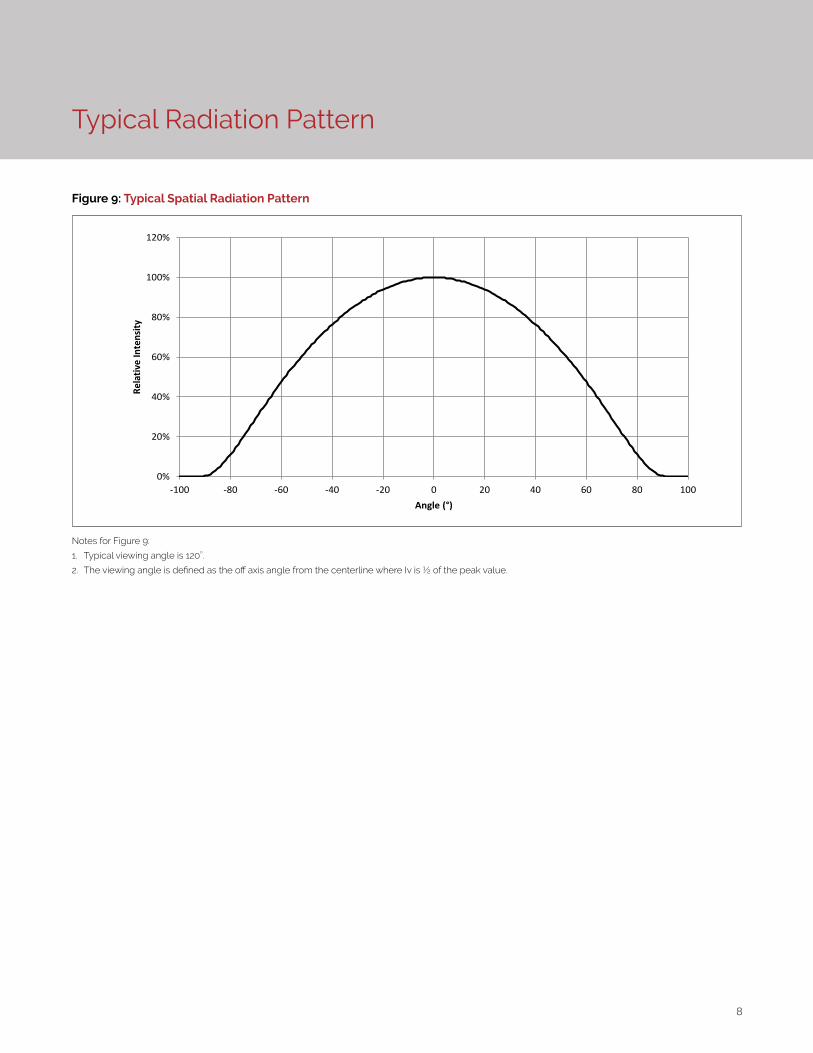
Figure 9: Typical Spatial Radiation Pattern
Notes for Figure 9:
1. Typical viewing angle is 120⁰.
2. The viewing angle is defined as the off axis angle from the centerline where Iv is ½ of the peak value.
0%
20%
40%
60%
80%
100%
120%
-100 -80 -60 -40 -20 0 20 40 60 80 100
Rela
tive
Inte
nsity
Angle (°)
9
Typical Color Spectrum
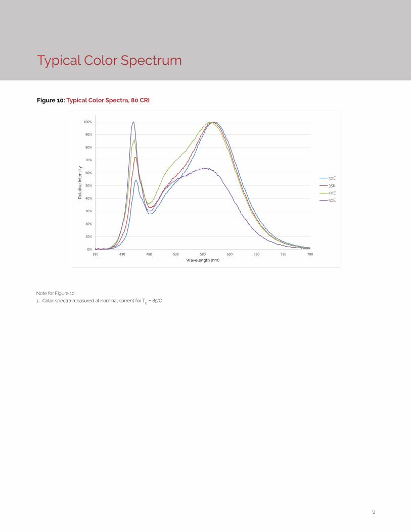
Figure 10: Typical Color Spectra, 80 CRI
0%
10%
20%
30%
40%
50%
60%
70%
80%
90%
100%
380 430 480 530 580 630 680 730 780
Re
lativ
e In
tens
ity
Wavelength (nm)
30E
35E
40E
50E
Note for Figure 10:
1. Color spectra measured at nominal current for Tc = 85°C
10
Mechanical Dimensions
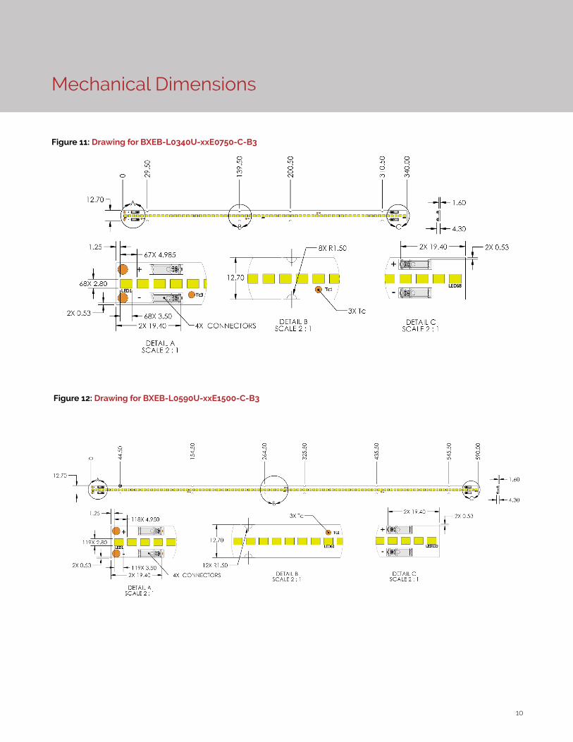
Figure 11: Drawing for BXEB-L0340U-xxE0750-C-B3
Figure 12: Drawing for BXEB-L0590U-xxE1500-C-B3
11
Table 5: Connector and wiring
Mechanical Dimensions
Parameter Specification
Input wire cross-section 20-24 AWG
Wire strip length 6.5-7.5 mm
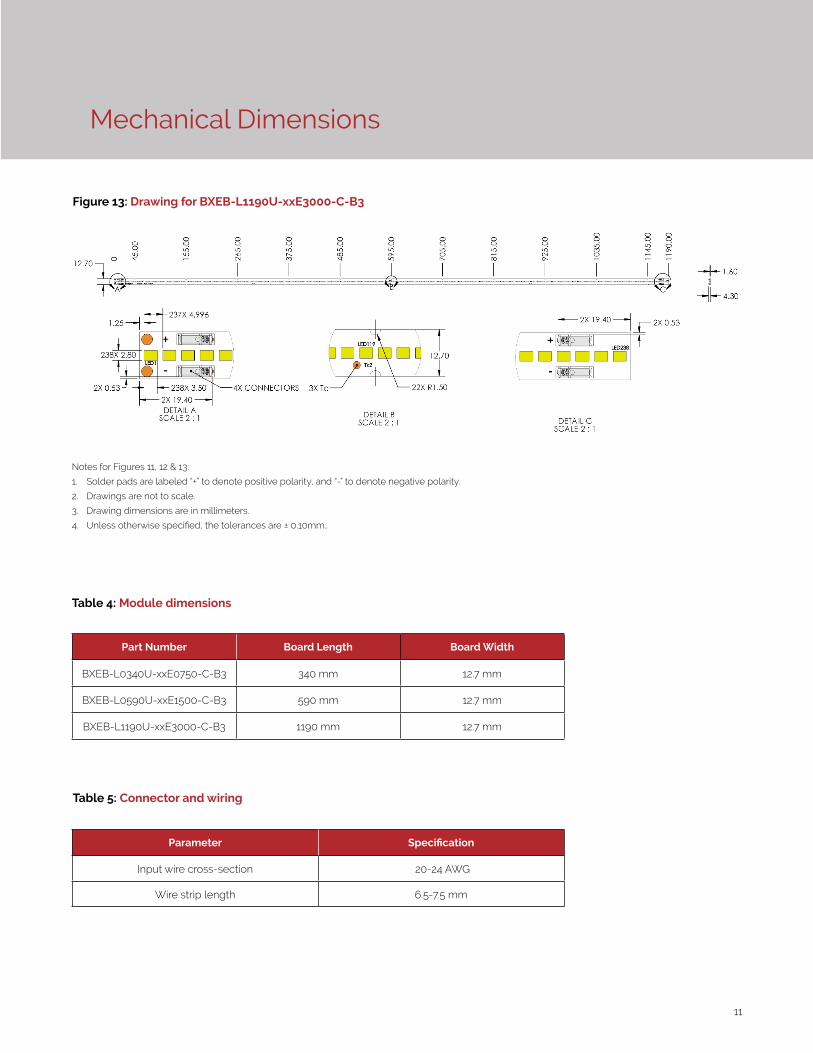
Notes for Figures 11, 12 & 13:
1. Solder pads are labeled “+” to denote positive polarity, and “-” to denote negative polarity.
2. Drawings are not to scale.
3. Drawing dimensions are in millimeters.
4. Unless otherwise specified, the tolerances are ± 0.10mm..
Figure 13: Drawing for BXEB-L1190U-xxE3000-C-B3
Part Number Board Length Board Width
BXEB-L0340U-xxE0750-C-B3 340 mm 12.7 mm
BXEB-L0590U-xxE1500-C-B3 590 mm 12.7 mm
BXEB-L1190U-xxE3000-C-B3 1190 mm 12.7 mm
Table 4: Module dimensions
12
Color Binning Information
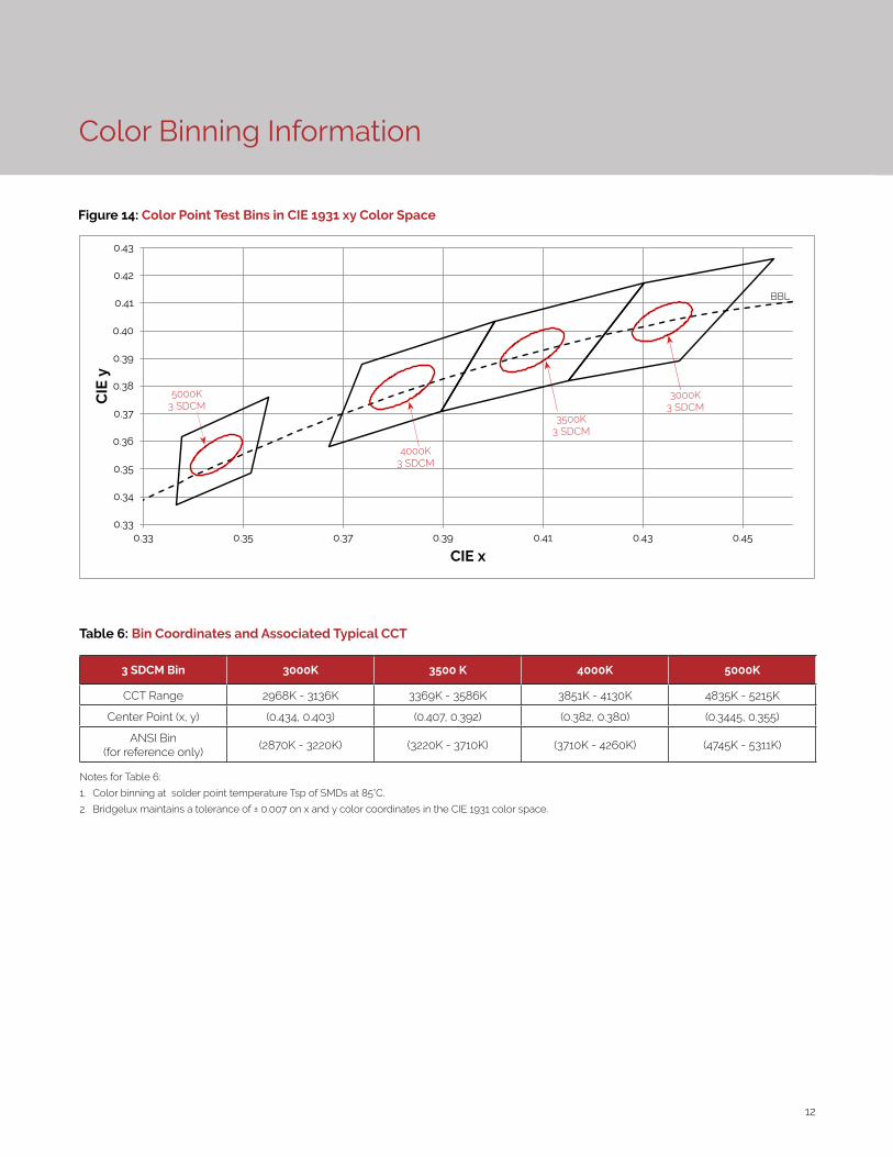
Figure 14: Color Point Test Bins in CIE 1931 xy Color Space
3 SDCM Bin 3000K 3500 K 4000K 5000K
CCT Range 2968K - 3136K 3369K - 3586K 3851K - 4130K 4835K - 5215K
Center Point (x, y) (0.434, 0.403) (0.407, 0.392) (0.382, 0.380) (0.3445, 0.355)
ANSI Bin (for reference only)
(2870K - 3220K) (3220K - 3710K) (3710K - 4260K) (4745K - 5311K)
Table 6: Bin Coordinates and Associated Typical CCT
Notes for Table 6:
1. Color binning at solder point temperature Tsp of SMDs at 85°C.
2. Bridgelux maintains a tolerance of ± 0.007 on x and y color coordinates in the CIE 1931 color space.
0.33
0.34
0.35
0.36
0.37
0.38
0.39
0.40
0.41
0.42
0.43
0.33 0.35 0.37 0.39 0.41 0.43 0.45
CIE
y
CIE x
3000K3 SDCM
3500K3 SDCM
4000K3 SDCM
5000K3 SDCM
BBL
13
Packaging and Labeling
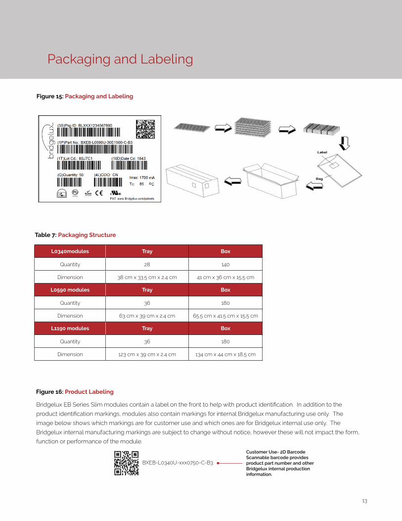
Figure 15: Packaging and Labeling
Customer Use- 2D Barcode Scannable barcode provides product part number and other Bridgelux internal production information.
BXEB-L0340U-xxx0750-C-B3
L0340modules Tray Box
Quantity 28 140
Dimension 38 cm x 33.5 cm x 2.4 cm 41 cm x 36 cm x 15.5 cm
L0590 modules Tray Box
Quantity 36 180
Dimension 63 cm x 39 cm x 2.4 cm 65.5 cm x 41.5 cm x 15.5 cm
L1190 modules Tray Box
Quantity 36 180
Dimension 123 cm x 39 cm x 2.4 cm 134 cm x 44 cm x 18.5 cm
Figure 16: Product Labeling
Bridgelux EB Series Slim modules contain a label on the front to help with product identification. In addition to the
product identification markings, modules also contain markings for internal Bridgelux manufacturing use only. The
image below shows which markings are for customer use and which ones are for Bridgelux internal use only. The
Bridgelux internal manufacturing markings are subject to change without notice, however these will not impact the form,
function or performance of the module.
Table 7: Packaging Structure
14
Design Resources
Disclaimers
Precautions
Application Notes
Bridgelux has developed a comprehensive set of application notes and design resources to assist customers in successfully designing with the EB Series product family. For a list of resources under development, visit www.bridgelux.com.
Optical Source Models
Optical source models and ray set files are available for all Bridgelux products. For a list of available formats, visit www.bridgelux.com.
MINOR PRODUCT CHANGE POLICY
The rigorous qualification testing on products offered by Bridgelux provides performance assurance. Slight cosmetic changes that do not affect form, fit, or function may occur as Bridgelux continues product optimization.
CAUTION: CHEMICAL EXPOSURE HAZARD
Exposure to some chemicals commonly used in luminaire manufacturing and assembly can cause damage to the LED linear. Please consult Bridgelux Application Note for additional information.
CAUTION: EYE SAFETY
Eye safety classification for the use of Bridgelux EB Series is in accordance with IEC/TR62778: Application of IEC 62471 for the assessment of blue light hazard to light sources and luminaires. EB Series linears are classified as Risk Group 1 when operated at or below the maximum drive current. Please use appropriate precautions. It is important that employees working with LEDs are trained to use them safely.
CAUTION: RISK OF BURN
Do not touch the EB Series modules during operation. Allow the linear to cool for a sufficient period of time be-fore handling. The EB Series linears may reach elevated temperatures such that could burn skin when touched.
3D CAD Models
Three dimensional CAD models depicting the product outline of all Bridgelux EB Series LED linears are available in both IGES and STEP formats. Please contact your Bridgelux sales representative for assistance.
CAUTION
CONTACT WITH LIGHT EMITTING SURFACE (LES)
Avoid any contact with the LES. Do not touch the LES of the linear or apply stress to the LES (yellow phosphor resin area). Contact may cause damage to the linear.
Optics and reflectors must not be mounted in con-tact with the LES (yellow phosphor resin area). Opti-cal devices may be mounted on the top surface of the EB Series linear. Use the mechanical features of the linear housing, edges and/or mounting holes to locate and secure optical devices as needed.
STANDARD TEST CONDITIONS
Unless otherwise stated, linear testing is performed at the nominal drive current.

15
About Bridgelux: Bridging Light and Life™
© 2019 Bridgelux, IncAll rights reserved. Product specifications are subject to change without notice. Bridgelux and the Bridgelux stylized logo design are registered trade-marks of Bridgelux, Inc. EB Series and Bridging Light and Life are trademarks of Bridgelux, Inc. All other trademarks are the property of their respective owners.
Bridgelux EB Series Slim Data Sheet DS170 Rev. A (06/2019)
46430 Fremont Blvd
Fremont, CA 94538 USA
Tel (925) 583-8400
Fax (925) 583-8401
www.bridgelux.com
At Bridgelux, we help companies, industries and people experience the power and possibility of light. Since 2002, we’ve designed LED solutions that are high performing, energy efficient, cost effective and easy to integrate. Our focus is on light’s impact on human behavior, delivering products that create better environments, experiences and returns—both experiential and financial. And our patented technology drives new platforms for commercial and industrial luminaires.
For more information about the company, please visit bridgelux.comtwitter.com/Bridgeluxfacebook.com/Bridgeluxyoutube.com/user/Bridgeluxlinkedin.com/company/bridgelux-inc-_2WeChat ID: BridgeluxInChina