Embed Size (px)
Citation preview

Bridgelux® Gen 7 Vero® 18 Array SeriesProduct Data Sheet DS92
BXRC-27x4000 | 30x4000 | 35x4000 | 40x4000 | 50x4001 | 57x4001 | 65x4001

Introduction
Vero represents a revolutionary advancement in chip on board (COB) light source technology and innovation. Vero
LED light sources simplify luminaire design and manufacturing processes, improve light quality, and define a platform
for future functionality integration.
Vero is available in four different light emitting surface (LES) configurations and has been engineered to reliably
operate over a broad current range, enabling new degrees of flexibility in luminaire design optimization. Vero arrays
deliver increased lumen density to enable improved beam control and precision lighting with 2 and 3 SDCM color
control standard for clean and consistent uniform lighting.
Vero includes an on board connector port to enable solder free electrical interconnect and simple easy to use
mounting features to enable plug-and-play installation.
Ve
roFeatures
• Efficacy of 155 lm/W typical
• Vero 18 lumen output performance ranges from 2,044 to 13232 lumens
• Broad range of CCT options from 2700K to 5000K
• CRI options include minimum 70, 80, and 90, 2 and 3 SDCM color control for 2700K-4000K CCT
• Reliable operation at up to 2X nominal drive current
• Radial die pattern and improved lumen density
• Thermally isolated solder pads
• Onboard connector port
• Top side part number markings
Benefits
• Broad application coverage for interior and exterior lighting
• Flexibility for application driven lighting design requirements
• High quality true color reproduction
• Uniform consistent white light
• Flexibility in design optimization
• Improved optical control
• Enhanced ease of use and manufacturability
• Solderless connectivity enables plug & play installation and field upgradability
• Improved inventory management and quality control
Pending Standards and Classifications: ENEC

Contents
Product Feature Map 2
Product Nomenclature 2
Product Selection Guide 3
Performance at Commonly Used Drive Currents 7
Electrical Characteristics 13
Absolute Maximum Ratings 14
Performance Curves 15
Typical Radiation Pattern 20
Typical Color Spectrum 21
Mechanical Dimensions 22
Color Binning Information 23
Packaging and Labeling 24
Design Resources 26
Precautions 26
Disclaimers 26
About Bridgelux 27
1

Product Feature Map
Vero 18 is the second largest form factor in the Vero family of next generation solid state light sources. In addition to delivering the performance and light quality required for many lighting applications, Vero incorporates
Product Nomenclature
The part number designation for Bridgelux Vero LED arrays is explained as follows:
several features to simplify the design integration and manufacturing process, accelerate time to market and reduce system costs. Please consult the Bridgelux Vero Array Series Product Brief for more information on the Vero family of products.
2
1 2 3 4 5 6 7 8 9 10 11 – 12 – 13 14
Product FamilyCCT Bin Options
2 = 2 SDCM3 = 3 SDCM4 = 4 SDCM
Flux Indicator
4000 = 4000lm4001 = 4000lm
Minimum CRIC = 70 CRIE = 80 CRIG = 90 CRI
Array Configuration
Nominal CCT27 = 2,700K30 = 3,000K35 = 3,500K40 = 4,000K50 = 5,000K57 = 5,700K65 = 6,500K
BXRC – 30 E 400 0 – C – 7 3
2D Bar code provides full manufacturing traceability
Polarity indication marks simplify manufacturing operator instructions
Optics location/mounting features
Mounting holes
Zhaga Book 3 compatible mounting locations
Solderless connector port enables simplified manufacturing processes, reduced inventory
carrying costs and can enable field upgradability
Thermally isolated solder pads reduce manufacturing cycle time and complexity
Tc Measurement point
Radial die configuration improves lumen density and beam control
Optional Molex Pico-EZmate™ connector harness (sold separately)
Top side part number marking improves inventory management and outgoing quality control
Color Targeting Designator0 = Cold Targeted1 = Hot Targeted
Gen. 7

Product Selection Guide
The following product configurations are available:
Table 1: Selection Guide, Pulsed Measurement Data (Tj = Tc = 25°C)
Notes for Tables 1:
1. Nominal CCT as defined by ANSI C78.377-2011. Prodcuts with CCTs 5000K-6500K are hot targetd to 85°C.
2. CRI values are minimums. Minimum R9 value for 80 CRI products is 0, the minimum R9 values for 90 CRI products is 50.
3. Drive current is referred to as nominal drive current.
4. Products tested under pulsed condition (10ms pulse width) at nominal test current where Tj (junction temperature) = Tc (case temperature) = 25°C.
5. Typical performance values are provided as a reference only and are not a guarantee of performance.
6. Bridgelux maintains a ±7% tolerance on flux measurements.
7. Minimum flux values at the nominal test current are guaranteed by 100% test.
Part NumberNominal CCT1
(K)CRI2
Nominal Drive Current3
(mA)
Typical Pulsed Flux4,5,6
Tc = 25ºC(lm)
Minimum Pulsed Flux6,7
Tc = 25ºC(lm)
Typical Vf (V)
Typical Power
(W)
Typical Efficacy (lm/W)
BXRC-27E4000-B-7X 2700 80 900 4644 4358 35.0 31.5 147
BXRC-27E4000-C-7X 2700 80 1170 6038 5555 35.0 41.0 147
BXRC-27E4000-D-7X 2700 80 1050 4515 4267 29.0 30.5 148
BXRC-27G4000-B-7X 2700 90 900 3870 3632 35.0 31.5 123
BXRC-27G4000-C-7X 2700 90 1170 5032 4629 35.0 41.0 123
BXRC-27G4000-D-7X 2700 90 1050 3763 3556 29.0 30.5 124
BXRC-30E4000-B-7X 3000 80 900 4883 4540 35.0 31.5 155
BXRC-30E4000-C-7X 3000 80 1170 6347 5787 35.0 41.0 155
BXRC-30E4000-D-7X 3000 80 1050 4720 4445 29.0 30.5 155
BXRC-30G4000-B-7X 3000 90 900 4015 3723 35.0 31.5 127
BXRC-30G4000-C-7X 3000 90 1170 5221 4803 35.0 41.0 127
BXRC-30G4000-D-7X 3000 90 1050 3904 3665 29.0 30.5 128
BXRC-35E4000-B-7X 3500 80 900 4983 4676 35.0 31.5 158
BXRC-35E4000-C-7X 3500 80 1170 6479 5960 35.0 41.0 158
BXRC-35E4000-D-7X 3500 80 1050 4845 4578 29.0 30.5 159
BXRC-35G4000-B-7X 3500 90 900 4160 3904 35.0 31.5 132
BXRC-35G4000-C-7X 3500 90 1170 5409 4977 35.0 41.0 132
BXRC-35G4000-D-7X 3500 90 1050 4045 3823 29.0 30.5 133
BXRC-40E4000-B-7X 4000 80 900 5031 4722 35.0 31.5 160
BXRC-40E4000-C-7X 4000 80 1170 6541 6018 35.0 41.0 160
BXRC-40E4000-D-7X 4000 80 1050 4892 4540 29.0 30.5 161
BXRC-40G4000-B-7X 4000 90 900 4305 4041 35.0 31.5 137
BXRC-40G4000-C-7X 4000 90 1170 5598 5150 35.0 41.0 137
BXRC-40G4000-D-7X 4000 90 1050 4186 3956 29.0 30.5 137
BXRC-50C4001-B-74 5000 70 900 5515 5176 35.0 31.5 175
BXRC-50C4001-C-74 5000 70 1170 7170 6597 35.0 41.0 175
BXRC-50C4001-D-74 5000 70 1050 5362 5060 29.0 30.5 176
BXRC-50E4001-B-74 5000 80 900 5184 4865 35.0 31.5 165
BXRC-50E4001-C-74 5000 80 1170 6740 6201 35.0 41.0 165
BXRC-50E4001-D-74 5000 80 1050 5040 4763 29.0 30.5 166
3

Product Selection Guide
The following product configurations are available:
Table 1: Selection Guide, Pulsed Measurement Data (Tj = Tc = 25°C) (contiunued)
Notes for Tables 1:
1. Nominal CCT as defined by ANSI C78.377-2011. Prodcuts with a CCT of 5000K-6500K are hot targetd to 85°C.
2. CRI values are minimums. Minimum R9 value for 80 CRI products is 0, the minimum R9 values for 90 CRI products is 50.
3. Drive current is referred to as nominal drive current.
4. Products tested under pulsed condition (10ms pulse width) at nominal test current where Tj (junction temperature) = Tc (case temperature) = 25°C.
5. Typical performance values are provided as a reference only and are not a guarantee of performance.
6. Bridgelux maintains a ±7% tolerance on flux measurements.
7. Minimum flux values at the nominal test current are guaranteed by 100% test.
Part NumberNominal CCT1
(K)CRI2
Nominal Drive Current3
(mA)
Typical Pulsed Flux4,5,6
Tc = 25ºC(lm)
Minimum Pulsed Flux6,7
Tc = 25ºC(lm)
Typical Vf (V)
Typical Power
(W)
Typical Efficacy (lm/W)
BXRC-50G4001-B-74 5000 90 900 4412 4140 35.0 31.5 140
BXRC-50G4001-C-74 5000 90 1170 5736 5277 35.0 41.0 140
BXRC-50G4001-D-74 5000 90 1050 4290 4054 29.0 30.5 141
BXRC-57C4001-B-74 5700 70 900 5321 4994 35.0 31.5 169
BXRC-57C4001-C-74 5700 70 1170 6919 6365 35.0 41.0 169
BXRC-57C4001-D-74 5700 70 1050 5174 4890 29.0 30.5 170
BXRC-57E4001-B-74 5700 80 900 5273 4949 35.0 31.5 167
BXRC-57E4001-C-74 5700 80 1170 6856 6308 35.0 41.0 167
BXRC-57E4001-D-74 5700 80 1050 5127 4845 29.0 30.5 168
BXRC-65C4001-B-74 6500 70 900 5418 5085 35.0 31.5 172
BXRC-65C4001-C-74 6500 70 1170 7045 6481 35.0 41.0 172
BXRC-65C4001-D-74 6500 70 1050 5268 4978 29.0 30.5 173
BXRC-65E4001-B-74 6500 80 900 5370 5039 35.0 31.5 170
BXRC-65E4001-C-74 6500 80 1170 6982 6423 35.0 41.0 170
BXRC-65E4001-D-74 6500 80 1050 5221 4934 29.0 30.5 171
4

Product Selection Guide
Table 2: Selection Guide, Stabilized DC Performance (Tc = 85°C) 4,5
Notes for Tables 2:
1. Nominal CCT as defined by ANSI C78.377-2011. Prodcuts with a CCT of 5000K-6500K are hot targetd to 85°C.
2. CRI values are minimums. Minimum R9 value for 80 CRI products is 0, the minimum R9 values for 90 CRI products is 50.
3. Drive current is referred to as nominal drive current.
4. Typical stabilized DC performance values are provided as reference only and are not a guarantee of performance.
5. Typical performance is estimated based on operation under DC (direct current) with LED array mounted onto a heat sink with thermal interface material and the case temperature maintained at 85°C. Based on Bridgelux test setup, values may vary depending on the thermal design of the luminaire and/or the exposed environment to which the product is subjected.
6. Minimum flux values at elevated temperatures are provided for reference only and are not guaranteed by 100% production testing. Based on Bridgelux test setup, values may vary depending on the thermal design of the luminaire and/or the exposed environment to which the product is subjected.
Part NumberNominal CCT1
(K)CRI2
Nominal Drive Current3
(mA)
Typical DC Flux4,5
Tc = 85ºC(lm)
Minimum DC Flux6
Tc = 85ºC(lm)
Typical Vf (V)
Typical Power
(W)
Typical Efficacy (lm/W)
BXRC-27E4000-B-7X 2700 80 900 4180 3923 34.1 30.7 136
BXRC-27E4000-C-7X 2700 80 1170 5434 5000 34.1 39.9 136
BXRC-27E4000-D-7X 2700 80 1050 4064 3840 28.3 29.7 137
BXRC-27G4000-B-7X 2700 90 900 3483 3269 34.1 30.7 113
BXRC-27G4000-C-7X 2700 90 1170 4529 4166 34.1 39.9 113
BXRC-27G4000-D-7X 2700 90 1050 3387 3200 28.3 29.7 114
BXRC-30E4000-B-7X 3000 80 900 4394 4086 34.1 30.7 143
BXRC-30E4000-C-7X 3000 80 1170 5713 5208 34.1 39.9 143
BXRC-30E4000-D-7X 3000 80 1050 4248 4001 28.3 29.7 143
BXRC-30G4000-B-7X 3000 90 900 3614 3351 34.1 30.7 118
BXRC-30G4000-C-7X 3000 90 1170 4699 4323 34.1 39.9 118
BXRC-30G4000-D-7X 3000 90 1050 3513 3299 28.3 29.7 118
BXRC-35E4000-B-7X 3500 80 900 4484 4208 34.1 30.7 146
BXRC-35E4000-C-7X 3500 80 1170 5831 5364 34.1 39.9 146
BXRC-35E4000-D-7X 3500 80 1050 4360 4121 28.3 29.7 147
BXRC-35G4000-B-7X 3500 90 900 3744 3514 34.1 30.7 122
BXRC-35G4000-C-7X 3500 90 1170 4868 4479 34.1 39.9 122
BXRC-35G4000-D-7X 3500 90 1050 3640 3440 28.3 29.7 123
BXRC-40E4000-B-7X 4000 80 900 4528 4250 34.1 30.7 148
BXRC-40E4000-C-7X 4000 80 1170 5887 5416 34.1 39.9 148
BXRC-40E4000-D-7X 4000 80 1050 4402 4086 28.3 29.7 148
BXRC-40G4000-B-7X 4000 90 900 3875 3637 34.1 30.7 126
BXRC-40G4000-C-7X 4000 90 1170 5038 4635 34.1 39.9 126
BXRC-40G4000-D-7X 4000 90 1050 3767 3560 28.3 29.7 127
BXRC-50C4001-B-74 5000 70 900 4963 4658 34.1 30.7 162
BXRC-50C4001-C-74 5000 70 1170 6453 5937 34.1 39.9 162
BXRC-50C4001-D-74 5000 70 1050 4826 4554 28.3 29.7 163
BXRC-50E4001-B-74 5000 80 900 4666 4379 34.1 30.7 152
BXRC-50E4001-C-74 5000 80 1170 6066 5581 34.1 39.9 152
BXRC-50E4001-D-74 5000 80 1050 4536 4287 28.3 29.7 153
5

Product Selection Guide
Table 2: Selection Guide, Stabilized DC Performance (Tc = 85°C) 4,5 (contiunued)
Notes for Tables 2:
1. Nominal CCT as defined by ANSI C78.377-2011. Prodcuts with a CCT of 5000K-6500K are hot targetd to 85°C.
2. CRI values are minimums. Minimum R9 value for 80 CRI products is 0, the minimum R9 values for 90 CRI products is 50.
3. Drive current is referred to as nominal drive current.
4. Typical stabilized DC performance values are provided as reference only and are not a guarantee of performance.
5. Typical performance is estimated based on operation under DC (direct current) with LED array mounted onto a heat sink with thermal interface material and the case temperature maintained at 85°C. Based on Bridgelux test setup, values may vary depending on the thermal design of the luminaire and/or the exposed environment to which the product is subjected.
6. Minimum flux values at elevated temperatures are provided for reference only and are not guaranteed by 100% production testing. Based on Bridgelux test setup, values may vary depending on the thermal design of the luminaire and/or the exposed environment to which the product is subjected.
Part NumberNominal CCT1
(K)CRI2
Nominal Drive Current3
(mA)
Typical DC Flux4,5
Tc = 85ºC(lm)
Minimum DC Flux6
Tc = 85ºC(lm)
Typical Vf (V)
Typical Power
(W)
Typical Efficacy (lm/W)
BXRC-50G4001-B-74 5000 90 900 3971 3726 34.1 30.7 129
BXRC-50G4001-C-74 5000 90 1170 5163 4750 34.1 39.9 129
BXRC-50G4001-D-74 5000 90 1050 3861 3648 28.3 29.7 130
BXRC-57C4001-B-74 5700 70 900 4789 4495 34.1 30.7 156
BXRC-57C4001-C-74 5700 70 1170 6227 5729 34.1 39.9 156
BXRC-57C4001-D-74 5700 70 1050 4656 4401 28.3 29.7 157
BXRC-57E4001-B-74 5700 80 900 4746 4454 34.1 30.7 155
BXRC-57E4001-C-74 5700 80 1170 6170 5677 34.1 39.9 155
BXRC-57E4001-D-74 5700 80 1050 4614 4361 28.3 29.7 155
BXRC-65C4001-B-74 6500 70 900 4876 4576 34.1 30.7 159
BXRC-65C4001-C-74 6500 70 1170 6340 5833 34.1 39.9 159
BXRC-65C4001-D-74 6500 70 1050 4741 4481 28.3 29.7 160
BXRC-65E4001-B-74 6500 80 900 4833 4535 34.1 30.7 157
BXRC-65E4001-C-74 6500 80 1170 6284 5781 34.1 39.9 157
BXRC-65E4001-D-74 6500 80 1050 4699 4441 28.3 29.7 158
6

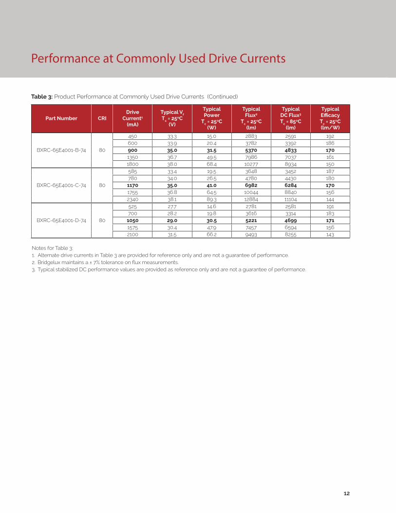
Performance at Commonly Used Drive Currents
Vero LED arrays are tested to the specifications shown using the nominal drive currents in Table 1. Vero may also
be driven at other drive currents dependent on specific application design requirements. The performance at any
drive current can be derived from the current vs. voltage characteristics shown in Figures 1, 2 & 3 and the flux vs. current
characteristics shown in Figures 4, 5 & 6. The performance at commonly used drive currents is summarized in Table 3.
7
Table 3: Product Performance at Commonly Used Drive Currents
Part Number CRIDrive
Current1
(mA)
Typical Vf Tc = 25ºC
(V)
Typical Power
Tc = 25ºC(W)
Typical Flux2
Tc = 25ºC(lm)
Typical DC Flux3 Tc = 85ºC
(lm)
Typical Efficacy Tc = 25ºC(lm/W)
BXRC-27E4000-B-7X 80
450 33.3 15.0 2493 2241 166600 33.9 20.4 3271 2934 161900 35.0 31.5 4644 4180 1471350 36.7 49.5 6907 6086 1401800 38.0 68.4 8888 7726 130
BXRC-27E4000-C-7X 80
585 33.4 19.5 3155 2986 162780 34.0 26.5 4134 3831 1561170 35.0 41.0 6038 5434 1471755 36.8 64.5 8687 7646 1352340 38.1 89.3 11143 9604 125
BXRC-27E4000-D-7X 80
525 27.7 14.6 2405 2233 165700 28.2 19.8 3128 2866 158
1050 29.0 30.5 4515 4064 1481575 30.4 47.9 6450 5703 1352100 31.5 66.2 8210 7140 124
BXRC-27G4000-B-7X 90
450 33.3 15.0 2078 1867 139600 33.9 20.4 2726 2445 134900 35.0 31.5 3870 3483 1231350 36.7 49.5 5756 5071 1161800 38.0 68.4 7407 6439 108
BXRC-27G4000-C-7X 90
585 33.4 19.5 2629 2488 135780 34.0 26.5 3445 3193 1301170 35.0 41.0 5032 4529 1231755 36.8 64.5 7239 6371 1122340 38.1 89.3 9286 8003 104
BXRC-27G4000-D-7X 90
525 27.7 14.6 2004 1861 138700 28.2 19.8 2606 2389 132
1050 29.0 30.5 3763 3387 1241575 30.4 47.9 5375 4753 1122100 31.5 66.2 6842 5950 103
Notes for Table 3:1. Alternate drive currents in Table 3 are provided for reference only and are not a guarantee of performance.2. Bridgelux maintains a ± 7% tolerance on flux measurements.3. Typical stabilized DC performance values are provided as reference only and are not a guarantee of performance.

8
Performance at Commonly Used Drive Currents
Notes for Table 3:1. Alternate drive currents in Table 3 are provided for reference only and are not a guarantee of performance.2. Bridgelux maintains a ± 7% tolerance on flux measurements.3. Typical stabilized DC performance values are provided as reference only and are not a guarantee of performance.
Table 3: Product Performance at Commonly Used Drive Currents (Continued)
Part Number CRIDrive
Current1
(mA)
Typical Vf Tc = 25ºC
(V)
Typical Power
Tc = 25ºC(W)
Typical Flux2
Tc = 25ºC(lm)
Typical DC Flux3 Tc = 85ºC
(lm)
Typical Efficacy Tc = 25ºC(lm/W)
BXRC-30E4000-B-7X 80
450 33.3 15.0 2621 2356 175600 33.9 20.4 3439 3084 169900 35.0 31.5 4883 4394 1551350 36.7 49.5 7262 6398 1471800 38.0 68.4 9345 8123 137
BXRC-30E4000-C-7X 80
585 33.4 19.5 3316 3139 170780 34.0 26.5 4346 4027 1641170 35.0 41.0 6347 5713 1551755 36.8 64.5 9131 8037 1422340 38.1 89.3 11713 10095 131
BXRC-30E4000-D-7X 80
525 27.7 14.6 2514 2334 173700 28.2 19.8 3269 2996 165
1050 29.0 30.5 4720 4248 1551575 30.4 47.9 6741 5961 1412100 31.5 66.2 8582 7463 130
BXRC-30G4000-B-7X 90
450 33.3 15.0 2156 1937 144600 33.9 20.4 2828 2536 139900 35.0 31.5 4015 3614 1271350 36.7 49.5 5972 5262 1211800 38.0 68.4 7685 6680 112
BXRC-30G4000-C-7X 90
585 33.4 19.5 2728 2581 140780 34.0 26.5 3574 3312 1351170 35.0 41.0 5221 4699 1271755 36.8 64.5 7510 6610 1162340 38.1 89.3 9634 8303 108
BXRC-30G4000-D-7X 90
525 27.7 14.6 2080 1930 143700 28.2 19.8 2704 2478 137
1050 29.0 30.5 3904 3513 1281575 30.4 47.9 5576 4931 1162100 31.5 66.2 7098 6173 107
BXRC-35E4000-B-7X 80
450 33.3 15.0 2675 2404 178600 33.9 20.4 3509 3148 172900 35.0 31.5 4983 4484 1581350 36.7 49.5 7411 6530 1501800 38.0 68.4 9536 8290 139
BXRC-35E4000-C-7X 80
585 33.4 19.5 3385 3203 173780 34.0 26.5 4436 4111 1671170 35.0 41.0 6479 5831 1581755 36.8 64.5 9320 8203 1442340 38.1 89.3 11955 10304 134
BXRC-35E4000-D-7X 80
525 27.7 14.6 2581 2395 177700 28.2 19.8 3356 3075 170
1050 29.0 30.5 4845 4360 1591575 30.4 47.9 6920 6119 1442100 31.5 66.2 8809 7660 133

9
Notes for Table 3:1. Alternate drive currents in Table 3 are provided for reference only and are not a guarantee of performance.2. Bridgelux maintains a ± 7% tolerance on flux measurements.3. Typical stabilized DC performance values are provided as reference only and are not a guarantee of performance.
Table 3: Product Performance at Commonly Used Drive Currents (Continued)
Part Number CRIDrive
Current1
(mA)
Typical Vf Tc = 25ºC
(V)
Typical Power
Tc = 25ºC(W)
Typical Flux2
Tc = 25ºC(lm)
Typical DC Flux3 Tc = 85ºC
(lm)
Typical Efficacy Tc = 25ºC(lm/W)
BXRC-35G4000-B-7X 90
450 33.3 15.0 2234 2007 149600 33.9 20.4 2930 2628 144900 35.0 31.5 4160 3744 1321350 36.7 49.5 6188 5452 1251800 38.0 68.4 7962 6921 116
BXRC-35G4000-C-7X 90
585 33.4 19.5 2826 2675 145780 34.0 26.5 3704 3432 1401170 35.0 41.0 5409 4868 1321755 36.8 64.5 7782 6849 1212340 38.1 89.3 9982 8603 112
BXRC-35G4000-D-7X 90
525 27.7 14.6 2155 2000 148700 28.2 19.8 2802 2568 142
1050 29.0 30.5 4045 3640 1331575 30.4 47.9 5778 5109 1212100 31.5 66.2 7355 6396 111
BXRC-40E4000-B-7X 80
450 33.3 15.0 2701 2427 180600 33.9 20.4 3543 3178 174900 35.0 31.5 5031 4528 1601350 36.7 49.5 7483 6593 1511800 38.0 68.4 9629 8370 141
BXRC-40E4000-C-7X 80
585 33.4 19.5 3418 3235 175780 34.0 26.5 4479 4151 1691170 35.0 41.0 6541 5887 1601755 36.8 64.5 9411 8283 1462340 38.1 89.3 12071 10404 135
BXRC-40E4000-D-7X 80
525 27.7 14.6 2606 2419 179700 28.2 19.8 3388 3105 171
1050 29.0 30.5 4892 4402 1611575 30.4 47.9 6987 6178 1462100 31.5 66.2 8894 7735 134
BXRC-40G4000-B-7X 90
450 33.3 15.0 2312 2077 154600 33.9 20.4 3032 2720 149900 35.0 31.5 4305 3875 1371350 36.7 49.5 6403 5642 1291800 38.0 68.4 8240 7163 120
BXRC-40G4000-C-7X 90
585 33.4 19.5 2925 2768 150780 34.0 26.5 3833 3552 1451170 35.0 41.0 5598 5038 1371755 36.8 64.5 8053 7088 1252340 38.1 89.3 10330 8903 116
BXRC-40G4000-D-7X 90
525 27.7 14.6 2230 2070 153700 28.2 19.8 2900 2657 147
1050 29.0 30.5 4186 3767 1371575 30.4 47.9 5979 5287 1252100 31.5 66.2 7612 6619 115
Performance at Commonly Used Drive Currents

10
Performance at Commonly Used Drive Currents
Notes for Table 3:1. Alternate drive currents in Table 3 are provided for reference only and are not a guarantee of performance.2. Bridgelux maintains a ± 7% tolerance on flux measurements.3. Typical stabilized DC performance values are provided as reference only and are not a guarantee of performance.
Table 3: Product Performance at Commonly Used Drive Currents (Continued)
Part Number CRIDrive
Current1
(mA)
Typical Vf Tc = 25ºC
(V)
Typical Power
Tc = 25ºC(W)
Typical Flux2
Tc = 25ºC(lm)
Typical DC Flux3 Tc = 85ºC
(lm)
Typical Efficacy Tc = 25ºC(lm/W)
BXRC-50C4001-B-74 70
450 33.3 15.0 2961 2661 197600 33.9 20.4 3884 3484 191900 35.0 31.5 5515 4963 1751350 36.7 49.5 8202 7227 1661800 38.0 68.4 10555 9175 154
BXRC-50C4001-C-74 70
585 33.4 19.5 3746 3546 192780 34.0 26.5 4909 4550 1851170 35.0 41.0 7170 6453 1751755 36.8 64.5 10315 9079 1602340 38.1 89.3 13232 11404 148
BXRC-50C4001-D-74 70
525 27.7 14.6 2856 2651 196700 28.2 19.8 3714 3404 188
1050 29.0 30.5 5362 4826 1761575 30.4 47.9 7659 6772 1602100 31.5 66.2 9750 8478 147
BXRC-50E4001-B-74 80
450 33.3 15.0 2783 2501 186600 33.9 20.4 3651 3275 179900 35.0 31.5 5184 4666 1651350 36.7 49.5 7710 6793 1561800 38.0 68.4 9922 8624 145
BXRC-50E4001-C-74 80
585 33.4 19.5 3522 3333 180780 34.0 26.5 4615 4277 1741170 35.0 41.0 6740 6066 1651755 36.8 64.5 9697 8535 1502340 38.1 89.3 12438 10720 139
BXRC-50E4001-D-74 80
525 27.7 14.6 2685 2492 184700 28.2 19.8 3491 3200 177
1050 29.0 30.5 5040 4536 1661575 30.4 47.9 7199 6366 1502100 31.5 66.2 9165 7970 138
BXRC-50G4001-B-74 90
450 33.3 15.0 2369 2128 158600 33.9 20.4 3107 2787 153900 35.0 31.5 4412 3971 1401350 36.7 49.5 6562 5782 1331800 38.0 68.4 8444 7340 123
BXRC-50G4001-C-74 90
585 33.4 19.5 2997 2836 154780 34.0 26.5 3928 3640 1481170 35.0 41.0 5736 5163 1401755 36.8 64.5 8252 7263 1282340 38.1 89.3 10585 9124 119
BXRC-50G4001-D-74 90
525 27.7 14.6 2285 2121 157700 28.2 19.8 2971 2723 150
1050 29.0 30.5 4290 3861 1411575 30.4 47.9 6127 5418 1282100 31.5 66.2 7800 6783 118

Performance at Commonly Used Drive Currents
11
Notes for Table 3:1. Alternate drive currents in Table 3 are provided for reference only and are not a guarantee of performance.2. Bridgelux maintains a ± 7% tolerance on flux measurements.3. Typical stabilized DC performance values are provided as reference only and are not a guarantee of performance.
Table 3: Product Performance at Commonly Used Drive Currents (Continued)
Part Number CRIDrive
Current1
(mA)
Typical Vf Tc = 25ºC
(V)
Typical Power
Tc = 25ºC(W)
Typical Flux2
Tc = 25ºC(lm)
Typical DC Flux3 Tc = 85ºC
(lm)
Typical Efficacy Tc = 25ºC(lm/W)
BXRC-57C4001-B-74 70
450 33.3 15.0 2857 2567 190600 33.9 20.4 3748 3361 184900 35.0 31.5 5321 4789 1691350 36.7 49.5 7914 6973 1601800 38.0 68.4 10184 8853 149
BXRC-57C4001-C-74 70
585 33.4 19.5 3615 3421 185780 34.0 26.5 4737 4390 1791170 35.0 41.0 6919 6227 1691755 36.8 64.5 9954 8761 1542340 38.1 89.3 12768 11004 143
BXRC-57C4001-D-74 70
525 27.7 14.6 2756 2558 189700 28.2 19.8 3584 3284 181
1050 29.0 30.5 5174 4656 1701575 30.4 47.9 7390 6535 1542100 31.5 66.2 9408 8181 142
BXRC-57E4001-B-74 80
450 33.3 15.0 2831 2544 189600 33.9 20.4 3714 3331 182900 35.0 31.5 5273 4746 1671350 36.7 49.5 7842 6910 1581800 38.0 68.4 10092 8773 147
BXRC-57E4001-C-74 80
585 33.4 19.5 3582 3390 184780 34.0 26.5 4694 4350 1771170 35.0 41.0 6856 6170 1671755 36.8 64.5 9863 8681 1532340 38.1 89.3 12651 10904 142
BXRC-57E4001-D-74 80
525 27.7 14.6 2731 2535 188700 28.2 19.8 3551 3254 180
1050 29.0 30.5 5127 4614 1681575 30.4 47.9 7323 6475 1532100 31.5 66.2 9322 8106 141
BXRC-65C4001-B-74 70
450 33.3 15.0 2909 2614 194600 33.9 20.4 3816 3423 187900 35.0 31.5 5418 4876 1721350 36.7 49.5 8058 7100 1631800 38.0 68.4 10370 9014 151
BXRC-65C4001-C-74 70
585 33.4 19.5 3681 3483 189780 34.0 26.5 4823 4470 1821170 35.0 41.0 7045 6340 1721755 36.8 64.5 10134 8920 1572340 38.1 89.3 13000 11204 146
BXRC-65C4001-D-74 70
525 27.7 14.6 2806 2605 193700 28.2 19.8 3649 3344 185
1050 29.0 30.5 5268 4741 1731575 30.4 47.9 7524 6654 1572100 31.5 66.2 9579 8330 145
12
Performance at Commonly Used Drive Currents
Notes for Table 3:1. Alternate drive currents in Table 3 are provided for reference only and are not a guarantee of performance.2. Bridgelux maintains a ± 7% tolerance on flux measurements.3. Typical stabilized DC performance values are provided as reference only and are not a guarantee of performance.
Table 3: Product Performance at Commonly Used Drive Currents (Continued)
Part Number CRIDrive
Current1
(mA)
Typical Vf Tc = 25ºC
(V)
Typical Power
Tc = 25ºC(W)
Typical Flux2
Tc = 25ºC(lm)
Typical DC Flux3 Tc = 85ºC
(lm)
Typical Efficacy Tc = 25ºC(lm/W)
BXRC-65E4001-B-74 80
450 33.3 15.0 2883 2591 192600 33.9 20.4 3782 3392 186900 35.0 31.5 5370 4833 1701350 36.7 49.5 7986 7037 1611800 38.0 68.4 10277 8934 150
BXRC-65E4001-C-74 80
585 33.4 19.5 3648 3452 187780 34.0 26.5 4780 4430 1801170 35.0 41.0 6982 6284 1701755 36.8 64.5 10044 8840 1562340 38.1 89.3 12884 11104 144
BXRC-65E4001-D-74 80
525 27.7 14.6 2781 2581 191700 28.2 19.8 3616 3314 183
1050 29.0 30.5 5221 4699 1711575 30.4 47.9 7457 6594 1562100 31.5 66.2 9493 8255 143

Electrical Characteristics
Notes for Table 4:
1. Parts are tested in pulsed conditions, Tc = 25°C. Pulse width is 10ms.
2. Voltage minimum and maximum are provided for reference only and are not a guarantee of performance.
3. Bridgelux maintains a tester tolerance of ± O.10V on forward voltage measurements.
4. Typical coefficient of forward voltage tolerance is ± O.1mV for nominal current.
5. Thermal resistance values are based from test data of a 3000K 80 CRI product.
6. Thermal resistance value was calculated using total electrical input power; optical power was not subtracted from input power. The thermal interface material used during testing is not included in the thermal resistance value.
7. Vf min hot and max cold values are provided as reference only and are not guaranteed by test. These values are provided to aid in driver design and selection over the operating range of the product.
Table 4: Electrical Characteristics
13
Part NumberDrive Current
(mA)
Forward VoltagePulsed, Tc = 25ºC (V) 1, 2, 3 Typical
Coefficient of Forward
Voltage4 ∆Vf/∆Tc
(mV/ºC)
Typical Thermal
Resistance Junction to Case5,6
Rj-c (ºC/W)
Driver Selection Voltages7
(V)
Minimum Typical MaximumVf Min.
Hot Tc = 105ºC
(V)
Vf Max. Cold
Tc = -40ºC (V)
BXRC-xxx400x-B-7x900 32.4 35.0 37.6 -14.9 0.15 31.2 38.6
1800 35.2 38.0 40.9 -14.9 0.19 34.0 41.8
BXRC-xxx400x-C-7x1170 32.4 35.0 37.6 -12.2 0.11 31.4 38.4
2340 35.3 38.1 41.0 -14.9 0.13 34.1 42.0
BXRC-xxx400x-D-7x1050 26.8 29.0 31.2 -14.9 0.16 25.6 32.1
2100 29.2 31.5 33.9 -12.2 0.19 28.2 34.7

14
Absolute Maximum Ratings
Parameter Maximum Rating
LED Junction Temperature (Tj) 125°C
Storage Temperature -40°C to +105°C
Operating Case Temperature1 (Tc) 105°C
Soldering Temperature2 350°C or lower for a maximum of 10seconds
BXRC-xxx400x-B-7x BXRC-xxx400x-C-7x BXRC-xxx400x-D-7x
Maximum Drive Current3 1800mA 2340mA 2100mA
Maximum Peak Pulsed Drive Current4 2571mA 3343mA 3000mA
Maximum Reverse Voltage5 -60V -60V -50V
Table 5: Maximum Ratings
Notes for Table 5:
1. For IEC 62717 requirement, please consult your Bridgelux sales representative.
2. Refer to Bridgelux Application Note AN31: Assembly Considerations for Bridgelux Vero LED Arrays.
3. Arrays may be driven at higher currents however lumen maintenance may be reduced.
4. Bridgelux recommends a maximum duty cycle of 10% and pulse width of 20 ms when operating LED Arrays at maximum peak pulsed current specified. Maximum peak pulsed currents indicate values where LED Arrays can be driven without catastrophic failures.
5. Light emitting diodes are not designed to be driven in reverse voltage and will not produce light under this condition. Maximum rating provided for reference only.

Performance Curves
Figure 1: Vero 18B Drive Current vs. Voltage (Tj = Tc = 25°C)
Figure 2: Vero 18C Drive Current vs. Voltage (Tj = Tc = 25°C)
15
0
200
400
600
800
1000
1200
1400
1600
1800
2000
32 33 34 35 36 37 38 39
Forw
ard
Cur
rent
(mA)
Forward Voltage (V)
0
300
600
900
1200
1500
1800
2100
2400
2700
32 33 34 35 36 37 38 39
Forw
ard
Cur
rent
(mA)
Forward Voltage (V)

Performance Curves
Figure 3: Vero 18D Drive Current vs. Voltage (Tj = Tc = 25°C)
Figure 4: Vero 18B Typical Relative Flux vs. Current( Tj = Tc = 25°C)
16
Note for Figure 4:
1. Bridgelux does not recommend driving high power LEDs at low currents. Doing so may produce unpredictable results. Pulse width modulation (PWM) is recommended for dimming effects.
0
250
500
750
1000
1250
1500
1750
2000
2250
26 27 28 29 30 31 32
Forw
ard
Cur
rent
(mA)
Forward Voltage (V)
0%
20%
40%
60%
80%
100%
120%
140%
160%
180%
200%
0 200 400 600 800 1000 1200 1400 1600 1800 2000
Rela
tive
Lum
inou
s Flu
x
Forward Current (mA)

Performance Curves
Figure 5: Vero 18C Typical Relative Flux vs. Current( Tj = Tc = 25°C)
Figure 6 Vero 18D Typical Relative Flux vs. Current( Tj = Tc = 25°C)
17
Note for Figures 5 & 6:
1. Bridgelux does not recommend driving high power LEDs at low currents. Doing so may produce unpredictable results. Pulse width modulation (PWM) is recommended for dimming effects.
0%
20%
40%
60%
80%
100%
120%
140%
160%
180%
200%
100 400 700 1000 1300 1600 1900 2200 2500
Rela
tive
Lum
inou
s Flu
x
Forward Current (mA)
0%
20%
40%
60%
80%
100%
120%
140%
160%
180%
200%
100 400 700 1000 1300 1600 1900 2200 2500
Rela
tive
Lum
inou
s Flu
x
Forward Current (mA)

Figure 7: Typical DC Flux vs. Case Temperature
Figure 8: Typical DC ccy Shift vs. Case Temperature
18
Performance Curves
Notes for Figures 7 & 8:
1. Characteristics shown for warm white based on 3000K and 80 CRI.2. Characteristics shown for neutral white based on 4000K and 80 CRI.3. Characteristics shown for cool white based on 5000K and 70 CRI.4. For other color SKUs, the shift in color will vary. Please contact your Bridgelux Sales Representative for more information.
82%
85%
88%
91%
94%
97%
100%
103%
0 25 50 75 100 125
Rela
tive
Lum
inou
s Flu
x
Case Temperature (°C)
Warm WhiteNeutral WhiteCool White25°C Pulsed
-0.015
-0.012
-0.009
-0.006
-0.003
0.000
0.0030 25 50 75 100 125
ccy
Shift
Case Temperature (°C)
Warm WhiteNeutral WhiteCool White25°C Pulsed
Performance Curves
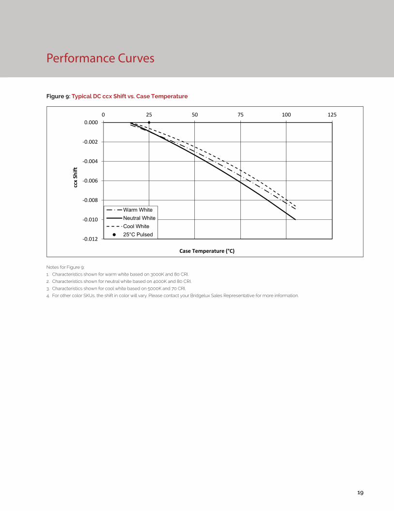
Figure 9: Typical DC ccx Shift vs. Case Temperature
19
Notes for Figure 9:
1. Characteristics shown for warm white based on 3000K and 80 CRI.
2. Characteristics shown for neutral white based on 4000K and 80 CRI.
3. Characteristics shown for cool white based on 5000K and 70 CRI.
4. For other color SKUs, the shift in color will vary. Please contact your Bridgelux Sales Representative for more information.
-0.012
-0.010
-0.008
-0.006
-0.004
-0.002
0.0000 25 50 75 100 125
ccx
Shift
Case Temperature (°C)
Warm WhiteNeutral WhiteCool White25°C Pulsed

Typical Radiation Pattern
Figure 10: Typical Spatial Radiation Pattern
Figure 11: Typical Polar Radiation Pattern
20
Note for Figure 10:
1. Typical viewing angle is 120⁰.
2. The viewing angle is defined as the off axis angle from the centerline where intensity is ½ of the peak value.

Typical Color Spectrum
Figure 12: Typical Color Spectrum
21
Note for Figure 12:
1. Color spectra measured at nominal current for Tj = Tc = 25°C.
2. Color spectra shown is 3000K and 80 CRI.
3. Color spectra shown is 4000K and 80 CRI.
4. Color spectra shown is 5000K and 70 CRI.
4. Color spectra shown is 6500K and 70 CRI.
0%
10%
20%
30%
40%
50%
60%
70%
80%
90%
100%
110%
400 450 500 550 600 650 700 750 800
Rela
tive
Spec
tral
Pow
er D
istr
ibut
ion
Wavelength (nm)
3000K4000K5000K6500K

Mechanical Dimensions
Figure 13: Drawing for Vero 18 LED Array
22
Notes for Figure 13:
1. Drawings are not to scale.
2. Drawing dimensions are in millimeters.
3. Unless otherwise specified, tolerances are ±0.1mm.
4. Mounting holes (2X) are for M2.5 screws.
5. Bridgelux recommends two tapped holes for mounting screws with 31.4 ± 0.10mm center-to-center spacing.
6. Screws with flat shoulders (pan, dome, button, round, truss, mushroom) provide optimal torque control. Do NOT use flat, countersink, or raised head screws.
7. Solder pads and connector port are labeled “+” and “-“ to denote positive and negative, respectively.
8. It is not necessary to provide electrical connections to both the solder pads and the connector port. Either set may be used depending on application specific design requirements.
9. Refer to Application Notes AN30 and AN31 for product handling, mounting and heat sink recommendations.
10. The optical center of the LED Array is nominally defined by the mechanical center of the array to a tolerance of ± 0.2mm.
11. Bridgelux maintains a flatness of 0.10mm across the mounting surface of the array.

Figure 14: Graph of Warm and Neutral White Test Bins in xy Color Space
Figure 15: Graph of Cool White Test Bins in xy Color Space
Color Binning Information
Bin Code 2700K 3000K 3500K 4000K
ANSI Bin(for reference only)
(2580K - 2870K) (2870K - 3220K) (3220K - 3710K) (3710K - 4260K)
23 (3 SDCM) (2651K - 2794K) (2968K - 3136K) (3369K - 3586K) (3851K - 4130K)
22 (2 SDCM) (2674K - 2769K) (2995K - 3107K) (3404K - 3548K) (3895K - 4081K)
Center Point (x,y) (0.4578, 0.4101) (0.4338, 0.403) (0.4073, 0.3917) (0.3818, 0.3797)
Table 6: Warm and Neutral White xy Bin Coordinates and Associated Typical CCT
Bin Code 5000K 5700K 6500K
ANSI Bin (for reference only) (4745K - 5311K) (5312K - 6022K) (6022K - 7042K)
4 (4 SDCM) (4801K - 5282K) (5829K - 5481K) (6270K - 6765K)
Center Point (x,y) (0.3447, 0.3553) (0.3287, 0.3417) (0.3123, 0.3282)
Table 7: Cool White xy Bin Coordinates and Associated Typical CCT (product is hot targeted to Tc = 85°C)
Note: Pulsed Test Conditions, Tc = 25°C
Note: Pulsed Test Conditions, Tc = 25°C
23

Packaging and Labeling
24
Figure 16: Drawing for Vero 18 Packaging Tray
Notes for Figure 16:
1. Dimensions are in millimeters.
2. Drawings are not to scale.

Packaging and Labeling
25
Figure 17: Vero Series Packaging and Labeling
Notes for Figure 17:
1. Each tray holds 100 COBs.
2. Each tray is vacuum sealed in an anti-static bag and placed in its own box.
3. Each tray, bag and box is to be labeled as shown above.
Figure 18: Gen. 7 Product Labeling
Bridgelux COB arrays have laser markings on the back side of the substrate to help with product identification. In
addition to the product identification markings, Bridgelux COB arrays also contain markings for internal Bridgelux
manufacturing use only. The image below shows which markings are for customer use and which ones are for
Bridgelux internal use only. The Bridgelux internal manufacturing markings are subject to change without notice,
however these will not impact the form, function or performance of the COB array.
Customer Use- 2D Barcode Scannable barcode provides product part number and other Bridgelux internal production information.
Customer Use- Product part number 30E4000C 73

Design Resources
Disclaimers
Precautions
Application Notes
Bridgelux has developed a comprehensive set of application notes and design resources to assist customers in successfully designing with the Vero product family of LED array products. For all available application notes visit www.bridgelux.com.
Optical Source Models
Optical source models and ray set files are available for all Bridgelux products. For a list of available formats, visit www.bridgelux.com.
MINOR PRODUCT CHANGE POLICY
The rigorous qualification testing on products offered by Bridgelux provides performance assurance. Slight cosmetic changes that do not affect form, fit, or function may occur as Bridgelux continues product optimization.
CAUTION: CHEMICAL EXPOSURE HAZARD
Exposure to some chemicals commonly used in luminaire manufacturing and assembly can cause damage to the LED array. Please consult Bridgelux Application Note AN31 for additional information.
CAUTION: EYE SAFETY
Eye safety classification for the use of Bridgelux Vero Series LED arrays is in accordance with specification IEC/TR 62778: Application of IEC 62471 for the assessment of blue light hazard to light sources and luminaires. Vero Series LED arrays are classified as Risk Group 2 (Moderate Risk) when operated at or below 2.5 times the nominal drive current. The Ethr value is 889.79 lux per IEC/TR 62778. Please use appropriate precautions. Under many operating conditions the Vero Series LED arrays are classified as Risk Group 1, for more information please contact your Bridgelux sales representative. It is important that employees working with LEDs are trained to use them safely.
3D CAD Models
Three dimensional CAD models depicting the product outline of all Bridgelux Vero LED arrays are available in both IGS and STEP formats. Please contact your Bridgelux sales representative for assistance.
LM80
LM80 testing is ongoing. Please contact your Bridgelux sales representative for more information.
26
CAUTION
CONTACT WITH LIGHT EMITTING SURFACE (LES)
Avoid any contact with the LES. Do not touch the LES of the LED array or apply stress to the LES (yellow phosphor resin area). Contact may cause damage to the LED array.
Optics and reflectors must not be mounted in contact with the LES (yellow phosphor resin area). Optical devices may be mounted on the top surface of the plastic housing of the Vero LED array. Use the mechanical features of the LED array housing, edges and/or mounting holes to locate and secure optical devices as needed.
STANDARD TEST CONDITIONS
Unless otherwise stated, array testing is performed at the nominal drive current.
CAUTION: RISK OF BURN
Do not touch the Vero LED array during operation. Allow the array to cool for a sufficient period of time before handling. The Vero LED array may reach elevated temperatures such that could burn skin when touched
27
About Bridgelux: We Build Light That Transforms
© 2016 Bridgelux, Inc. All rights reserved 2016. Product specifications are subject to change without notice. Bridgelux, the Bridgelux stylized logo design and Vero are registered trademarks, and Decor Series is a trademark of Bridgelux, Inc. All other trademarks are the property of their respective owners.
Bridgelux Gen 7 Vero 18 Array Series Product Data Sheet DS92 Rev. A (06/2016)
101 Portola Avenue
Livermore, CA 94551
Tel (925) 583-8400
Fax (925) 583-8410
www.bridgelux.com
At Bridgelux, we help companies, industries and people experience the power and possibility of light. Since 2002, we’ve designed LED solutions that are high performing, energy efficient, cost effective and easy to integrate. Our focus is on light’s impact on human behavior, deliver-ing products that create better environments, experiences and returns—both experiential and financial. And our patented technology drives new platforms for commercial and industrial luminaires.
For more information about the company, please visit bridgelux.comtwitter.com/Bridgeluxfacebook.com/BridgeluxWeChat ID: BridgeluxInChina