Embed Size (px)
Citation preview
Bridgelux® Gen 7 Vero® 29 Array SeriesProduct Data Sheet DS93
BXRC-27x10K0 | 30x10K0 | 35x10K0 | 40x10K0 | 50x10K1 | 57x10K1 | 65x10K1
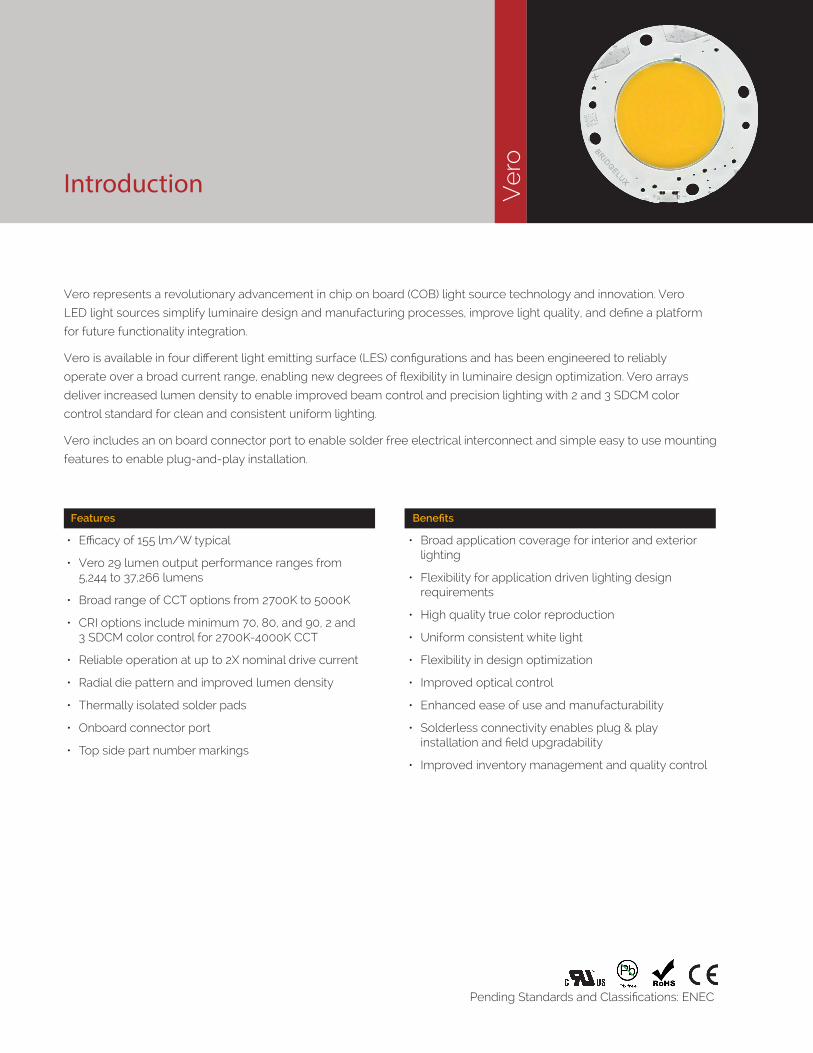
Introduction
Vero represents a revolutionary advancement in chip on board (COB) light source technology and innovation. Vero
LED light sources simplify luminaire design and manufacturing processes, improve light quality, and define a platform
for future functionality integration.
Vero is available in four different light emitting surface (LES) configurations and has been engineered to reliably
operate over a broad current range, enabling new degrees of flexibility in luminaire design optimization. Vero arrays
deliver increased lumen density to enable improved beam control and precision lighting with 2 and 3 SDCM color
control standard for clean and consistent uniform lighting.
Vero includes an on board connector port to enable solder free electrical interconnect and simple easy to use mounting
features to enable plug-and-play installation.
Ve
roFeatures
• Efficacy of 155 lm/W typical
• Vero 29 lumen output performance ranges from 5,244 to 37,266 lumens
• Broad range of CCT options from 2700K to 5000K
• CRI options include minimum 70, 80, and 90, 2 and 3 SDCM color control for 2700K-4000K CCT
• Reliable operation at up to 2X nominal drive current
• Radial die pattern and improved lumen density
• Thermally isolated solder pads
• Onboard connector port
• Top side part number markings
Benefits
• Broad application coverage for interior and exterior lighting
• Flexibility for application driven lighting design requirements
• High quality true color reproduction
• Uniform consistent white light
• Flexibility in design optimization
• Improved optical control
• Enhanced ease of use and manufacturability
• Solderless connectivity enables plug & play installation and field upgradability
• Improved inventory management and quality control
Pending Standards and Classifications: ENEC

Contents
Product Feature Map 2
Product Nomenclature 2
Product Selection Guide 3
Performance at Commonly Used Drive Currents 7
Electrical Characteristics 13
Absolute Maximum Ratings 14
Performance Curves 15
Typical Radiation Pattern 20
Typical Color Spectrum 21
Mechanical Dimensions 22
Color Binning Information 23
Packaging and Labeling 24
Design Resources 26
Precautions 26
Disclaimers 26
About Bridgelux 27
1
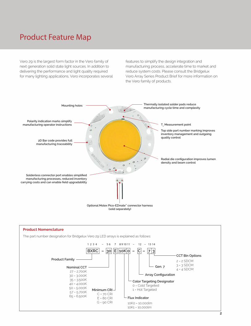
Product Feature Map
Vero 29 is the largest form factor in the Vero family of next generation solid state light sources. In addition to delivering the performance and light quality required for many lighting applications, Vero incorporates several
Product Nomenclature
The part number designation for Bridgelux Vero 29 LED arrays is explained as follows:
features to simplify the design integration and manufacturing process, accelerate time to market and reduce system costs. Please consult the Bridgelux Vero Array Series Product Brief for more information on the Vero family of products.
2
1 2 3 4 – 5 6 7 8 9 10 11 – 12 – 13 14
Product FamilyCCT Bin Options
2 = 2 SDCM3 = 3 SDCM4 = 4 SDCM
Flux Indicator
10K0 = 10,000lm10K1 = 10,000lm
Minimum CRIC = 70 CRIE = 80 CRIG = 90 CRI
Array Configuration
Nominal CCT27 = 2,700K30 = 3,000K35 = 3,500K40 = 4,000K50 = 5,000K57 = 5,700K65 = 6,500K
BXRC – 30 E 10K 0 – C – 7 3
Mounting holes
Polarity indication marks simplify manufacturing operator instructions
2D Bar code provides full manufacturing traceability
Solderless connector port enables simplified manufacturing processes, reduced inventory
carrying costs and can enable field upgradability
Thermally isolated solder pads reduce manufacturing cycle time and complexity
Tc Measurement point
Top side part number marking improves inventory management and outgoing quality control
Radial die configuration improves lumen density and beam control
Optional Molex Pico-EZmate™ connector harness (sold separately)
Color Targeting Designator0 = Cold Targeted1 = Hot Targeted
Gen. 7

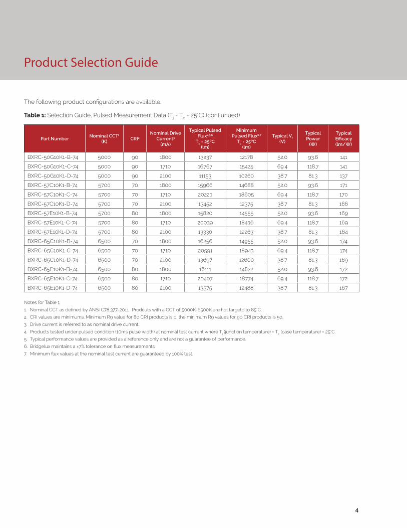
Product Selection Guide
The following product configurations are available:
Table 1: Selection Guide, Pulsed Measurement Data (Tj = Tc = 25°C)
Notes for Tables 1:
1. Nominal CCT as defined by ANSI C78.377-2011. Prodcuts with CCTs 5000K-6500K are hot targetd to 85°C.
2. CRI values are minimums. Minimum R9 value for 80 CRI products is 0, the minimum R9 values for 90 CRI products is 50.
3. Drive current is referred to as nominal drive current.
4. Products tested under pulsed condition (10ms pulse width) at nominal test current where Tj (junction temperature) = Tc (case temperature) = 25°C.
5. Typical performance values are provided as a reference only and are not a guarantee of performance.
6. Bridgelux maintains a ±7% tolerance on flux measurements.
7. Minimum flux values at the nominal test current are guaranteed by 100% test.
Part NumberNominal CCT1
(K)CRI2
Nominal Drive Current3
(mA)
Typical Pulsed Flux4,5,6
Tc = 25ºC(lm)
Minimum Pulsed Flux6,7
Tc = 25ºC(lm)
Typical Vf (V)
Typical Power
(W)
Typical Efficacy (lm/W)
BXRC-27E10K0-B-7X 2700 80 1800 13934 12819 52.0 93.6 149
BXRC-27E10K0-C-7X 2700 80 1710 17649 16237 69.4 118.7 149
BXRC-27E10K0-D-7X 2700 80 2100 11740 10800 38.7 81.3 144
BXRC-27G10K0-B-7X 2700 90 1800 11611 10682 52.0 93.6 124
BXRC-27G10K0-C-7X 2700 90 1710 14708 13531 69.4 118.7 124
BXRC-27G10K0-D-7X 2700 90 2100 9784 9000 38.7 81.3 120
BXRC-30E10K0-B-7X 3000 80 1800 14514 13353 52.0 93.6 155
BXRC-30E10K0-C-7X 3000 80 1710 18385 16914 69.4 118.7 155
BXRC-30E10K0-D-7X 3000 80 2100 12597 11250 38.7 81.3 155
BXRC-30G10K0-B-7X 3000 90 1800 12047 11083 52.0 93.6 129
BXRC-30G10K0-C-7X 3000 90 1710 15259 14038 69.4 118.7 129
BXRC-30G10K0-D-7X 3000 90 2100 10150 9338 38.7 81.3 125
BXRC-35E10K0-B-7X 3500 80 1800 14950 13754 52.0 93.6 160
BXRC-35E10K0-C-7X 3500 80 1710 18936 17421 69.4 118.7 160
BXRC-35E10K0-D-7X 3500 80 2100 12596 11588 38.7 81.3 155
BXRC-35G10K0-B-7X 3500 90 1800 12482 11484 52.0 93.6 133
BXRC-35G10K0-C-7X 3500 90 1710 15811 14546 69.4 118.7 133
BXRC-35G10K0-D-7X 3500 90 2100 10517 9675 38.7 81.3 129
BXRC-40E10K0-B-7X 4000 80 1800 15095 13887 52.0 93.6 161
BXRC-40E10K0-C-7X 4000 80 1710 19120 17590 69.4 118.7 161
BXRC-40E10K0-D-7X 4000 80 2100 12719 11700 38.7 81.3 156
BXRC-40G10K0-B-7X 4000 90 1800 12918 11884 52.0 93.6 138
BXRC-40G10K0-C-7X 4000 90 1710 16362 15053 69.4 118.7 138
BXRC-40G10K0-D-7X 4000 90 2100 10884 10013 38.7 81.3 134
BXRC-50C10K1-B-74 5000 70 1800 16546 15222 52.0 93.6 177
BXRC-50C10K1-C-74 5000 70 1710 20958 19282 69.4 118.7 177
BXRC-50C10K1-D-74 5000 70 2100 13942 12825 38.7 81.3 172
BXRC-50E10K1-B-74 5000 80 1800 15553 14309 52.0 93.6 166
BXRC-50E10K1-C-74 5000 80 1710 19701 18125 69.4 118.7 166
BXRC-50E10K1-D-74 5000 80 2100 13105 12056 38.7 81.3 161
3
Product Selection Guide
The following product configurations are available:
Table 1: Selection Guide, Pulsed Measurement Data (Tj = Tc = 25°C) (contiunued)
Notes for Table 1:
1. Nominal CCT as defined by ANSI C78.377-2011. Prodcuts with a CCT of 5000K-6500K are hot targetd to 85°C.
2. CRI values are minimums. Minimum R9 value for 80 CRI products is 0, the minimum R9 values for 90 CRI products is 50.
3. Drive current is referred to as nominal drive current.
4. Products tested under pulsed condition (10ms pulse width) at nominal test current where Tj (junction temperature) = Tc (case temperature) = 25°C.
5. Typical performance values are provided as a reference only and are not a guarantee of performance.
6. Bridgelux maintains a ±7% tolerance on flux measurements.
7. Minimum flux values at the nominal test current are guaranteed by 100% test.
Part NumberNominal CCT1
(K)CRI2
Nominal Drive Current3
(mA)
Typical Pulsed Flux4,5,6
Tc = 25ºC(lm)
Minimum Pulsed Flux6,7
Tc = 25ºC(lm)
Typical Vf (V)
Typical Power
(W)
Typical Efficacy (lm/W)
BXRC-50G10K1-B-74 5000 90 1800 13237 12178 52.0 93.6 141
BXRC-50G10K1-C-74 5000 90 1710 16767 15425 69.4 118.7 141
BXRC-50G10K1-D-74 5000 90 2100 11153 10260 38.7 81.3 137
BXRC-57C10K1-B-74 5700 70 1800 15966 14688 52.0 93.6 171
BXRC-57C10K1-C-74 5700 70 1710 20223 18605 69.4 118.7 170
BXRC-57C10K1-D-74 5700 70 2100 13452 12375 38.7 81.3 166
BXRC-57E10K1-B-74 5700 80 1800 15820 14555 52.0 93.6 169
BXRC-57E10K1-C-74 5700 80 1710 20039 18436 69.4 118.7 169
BXRC-57E10K1-D-74 5700 80 2100 13330 12263 38.7 81.3 164
BXRC-65C10K1-B-74 6500 70 1800 16256 14955 52.0 93.6 174
BXRC-65C10K1-C-74 6500 70 1710 20591 18943 69.4 118.7 174
BXRC-65C10K1-D-74 6500 70 2100 13697 12600 38.7 81.3 169
BXRC-65E10K1-B-74 6500 80 1800 16111 14822 52.0 93.6 172
BXRC-65E10K1-C-74 6500 80 1710 20407 18774 69.4 118.7 172
BXRC-65E10K1-D-74 6500 80 2100 13575 12488 38.7 81.3 167
4

Product Selection Guide
Table 2: Selection Guide, Stabilized DC Performance (Tc = 85°C) 4,5
Notes for Tables 2:
1. Nominal CCT as defined by ANSI C78.377-2011. Prodcuts with a CCT of 5000K-6500K are hot targetd to 85°C.
2. CRI values are minimums. Minimum R9 value for 80 CRI products is 0, the minimum R9 values for 90 CRI products is 50.
3. Drive current is referred to as nominal drive current.
4. Typical stabilized DC performance values are provided as reference only and are not a guarantee of performance.
5. Typical performance is estimated based on operation under DC (direct current) with LED array mounted onto a heat sink with thermal interface material and the case temperature maintained at 85°C. Based on Bridgelux test setup, values may vary depending on the thermal design of the luminaire and/or the exposed environment to which the product is subjected.
6. Minimum flux values at elevated temperatures are provided for reference only and are not guaranteed by 100% production testing. Based on Bridgelux test setup, values may vary depending on the thermal design of the luminaire and/or the exposed environment to which the product is subjected.
Part NumberNominal CCT1
(K)CRI2
Nominal Drive Current3
(mA)
Typical DC Flux4,5
Tc = 85ºC(lm)
Minimum DC Flux6
Tc = 85ºC(lm)
Typical Vf (V)
Typical Power
(W)
Typical Efficacy (lm/W)
BXRC-27E10K0-B-7X 2700 80 1800 12540 11537 50.7 91.2 137
BXRC-27E10K0-C-7X 2700 80 1710 15884 14614 68.1 116.4 136
BXRC-27E10K0-D-7X 2700 80 2100 10566 9720 37.7 79.1 134
BXRC-27G10K0-B-7X 2700 90 1800 10450 9614 50.7 91.2 115
BXRC-27G10K0-C-7X 2700 90 1710 13237 12178 68.1 116.4 114
BXRC-27G10K0-D-7X 2700 90 2100 8805 8100 37.7 79.1 111
BXRC-30E10K0-B-7X 3000 80 1800 13063 12018 50.7 91.2 143
BXRC-30E10K0-C-7X 3000 80 1710 16546 15222 68.1 116.4 142
BXRC-30E10K0-D-7X 3000 80 2100 11337 10125 37.7 79.1 143
BXRC-30G10K0-B-7X 3000 90 1800 10842 9975 50.7 91.2 119
BXRC-30G10K0-C-7X 3000 90 1710 13733 12635 68.1 116.4 118
BXRC-30G10K0-D-7X 3000 90 2100 9135 8404 37.7 79.1 116
BXRC-35E10K0-B-7X 3500 80 1800 13455 12378 50.7 91.2 148
BXRC-35E10K0-C-7X 3500 80 1710 17042 15679 68.1 116.4 146
BXRC-35E10K0-D-7X 3500 80 2100 11337 10429 37.7 79.1 143
BXRC-35G10K0-B-7X 3500 90 1800 11234 10335 50.7 91.2 123
BXRC-35G10K0-C-7X 3500 90 1710 14230 13091 68.1 116.4 122
BXRC-35G10K0-D-7X 3500 90 2100 9466 8708 37.7 79.1 120
BXRC-40E10K0-B-7X 4000 80 1800 13585 12498 50.7 91.2 149
BXRC-40E10K0-C-7X 4000 80 1710 17208 15831 68.1 116.4 148
BXRC-40E10K0-D-7X 4000 80 2100 11447 10530 37.7 79.1 145
BXRC-40G10K0-B-7X 4000 90 1800 11626 10696 50.7 91.2 127
BXRC-40G10K0-C-7X 4000 90 1710 14726 13548 68.1 116.4 127
BXRC-40G10K0-D-7X 4000 90 2100 9796 9011 37.7 79.1 124
BXRC-50C10K1-B-74 5000 70 1800 14892 13700 50.7 91.2 163
BXRC-50C10K1-C-74 5000 70 1710 18863 17354 68.1 116.4 162
BXRC-50C10K1-D-74 5000 70 2100 12547 11543 37.7 79.1 159
BXRC-50E10K1-B-74 5000 80 1800 13998 12878 50.7 91.2 153
BXRC-50E10K1-C-74 5000 80 1710 17731 16312 68.1 116.4 152
BXRC-50E10K1-D-74 5000 80 2100 11795 10850 37.7 79.1 149
5

Product Selection Guide
Table 2: Selection Guide, Stabilized DC Performance (Tc = 85°C) 4,5 (contiunued)
Notes for Tables 2:
1. Nominal CCT as defined by ANSI C78.377-2011. Prodcuts with a CCT of 5000K-6500K are hot targetd to 85°C.
2. CRI values are minimums. Minimum R9 value for 80 CRI products is 0, the minimum R9 values for 90 CRI products is 50.
3. Drive current is referred to as nominal drive current.
4. Typical stabilized DC performance values are provided as reference only and are not a guarantee of performance.
5. Typical performance is estimated based on operation under DC (direct current) with LED array mounted onto a heat sink with thermal interface material and the case temperature maintained at 85°C. Based on Bridgelux test setup, values may vary depending on the thermal design of the luminaire and/or the exposed environment to which the product is subjected.
6. Minimum flux values at elevated temperatures are provided for reference only and are not guaranteed by 100% production testing. Based on Bridgelux test setup, values may vary depending on the thermal design of the luminaire and/or the exposed environment to which the product is subjected.
Part NumberNominal CCT1
(K)CRI2
Nominal Drive Current3
(mA)
Typical DC Flux4,5
Tc = 85ºC(lm)
Minimum DC Flux6
Tc = 85ºC(lm)
Typical Vf (V)
Typical Power
(W)
Typical Efficacy (lm/W)
BXRC-50G10K1-B-74 5000 90 1800 11913 10960 50.7 91.2 131
BXRC-50G10K1-C-74 5000 90 1710 15090 13883 68.1 116.4 130
BXRC-50G10K1-D-74 5000 90 2100 10038 9234 37.7 79.1 127
BXRC-57C10K1-B-74 5700 70 1800 14369 13220 50.7 91.2 158
BXRC-57C10K1-C-74 5700 70 1710 18201 16745 68.1 116.4 156
BXRC-57C10K1-D-74 5700 70 2100 12107 11138 37.7 79.1 153
BXRC-57E10K1-B-74 5700 80 1800 14238 13099 50.7 91.2 156
BXRC-57E10K1-C-74 5700 80 1710 18035 16592 68.1 116.4 155
BXRC-57E10K1-D-74 5700 80 2100 11997 11036 37.7 79.1 152
BXRC-65C10K1-B-74 6500 70 1800 14630 13460 50.7 91.2 160
BXRC-65C10K1-C-74 6500 70 1710 18532 17049 68.1 116.4 159
BXRC-65C10K1-D-74 6500 70 2100 12327 11340 37.7 79.1 156
BXRC-65E10K1-B-74 6500 80 1800 14500 13340 50.7 91.2 159
BXRC-65E10K1-C-74 6500 80 1710 18366 16897 68.1 116.4 158
BXRC-65E10K1-D-74 6500 80 2100 12217 11239 37.7 79.1 154
6
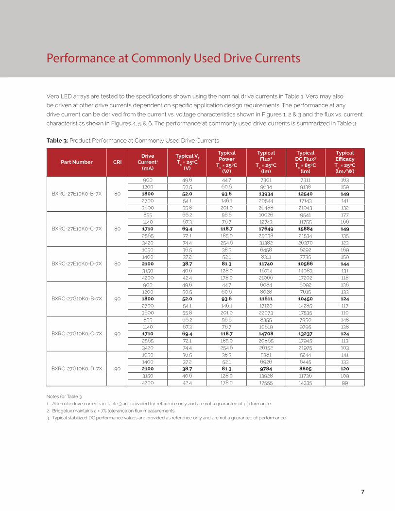
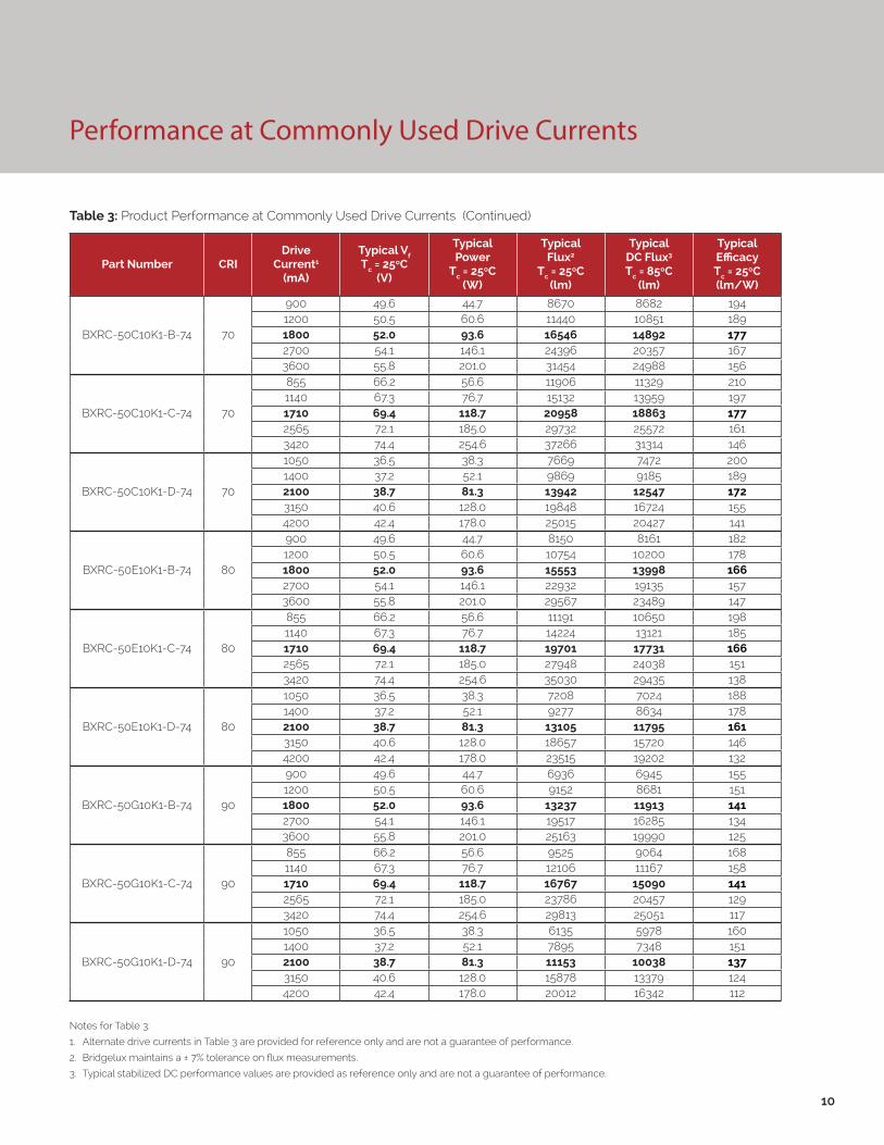
Performance at Commonly Used Drive Currents
Vero LED arrays are tested to the specifications shown using the nominal drive currents in Table 1. Vero may also
be driven at other drive currents dependent on specific application design requirements. The performance at any
drive current can be derived from the current vs. voltage characteristics shown in Figures 1, 2 & 3 and the flux vs. current
characteristics shown in Figures 4, 5 & 6. The performance at commonly used drive currents is summarized in Table 3.
7
Table 3: Product Performance at Commonly Used Drive Currents
Part Number CRIDrive
Current1
(mA)
Typical Vf Tc = 25ºC
(V)
Typical Power
Tc = 25ºC(W)
Typical Flux2
Tc = 25ºC(lm)
Typical DC Flux3 Tc = 85ºC
(lm)
Typical Efficacy Tc = 25ºC(lm/W)
BXRC-27E10K0-B-7X 80
900 49.6 44.7 7301 7311 1631200 50.5 60.6 9634 9138 1591800 52.0 93.6 13934 12540 1492700 54.1 146.1 20544 17143 1413600 55.8 201.0 26488 21043 132
BXRC-27E10K0-C-7X 80
855 66.2 56.6 10026 9541 1771140 67.3 76.7 12743 11755 1661710 69.4 118.7 17649 15884 1492565 72.1 185.0 25038 21534 1353420 74.4 254.6 31382 26370 123
BXRC-27E10K0-D-7X 80
1050 36.5 38.3 6458 6292 1691400 37.2 52.1 8311 7735 1592100 38.7 81.3 11740 10566 1443150 40.6 128.0 16714 14083 1314200 42.4 178.0 21066 17202 118
BXRC-27G10K0-B-7X 90
900 49.6 44.7 6084 6092 1361200 50.5 60.6 8028 7615 1331800 52.0 93.6 11611 10450 1242700 54.1 146.1 17120 14285 1173600 55.8 201.0 22073 17535 110
BXRC-27G10K0-C-7X 90
855 66.2 56.6 8355 7950 1481140 67.3 76.7 10619 9795 1381710 69.4 118.7 14708 13237 1242565 72.1 185.0 20865 17945 1133420 74.4 254.6 26152 21975 103
BXRC-27G10K0-D-7X 90
1050 36.5 38.3 5381 5244 1411400 37.2 52.1 6926 6445 1332100 38.7 81.3 9784 8805 1203150 40.6 128.0 13928 11736 1094200 42.4 178.0 17555 14335 99
Notes for Table 3:
1. Alternate drive currents in Table 3 are provided for reference only and are not a guarantee of performance.
2. Bridgelux maintains a ± 7% tolerance on flux measurements.
3. Typical stabilized DC performance values are provided as reference only and are not a guarantee of performance.

8
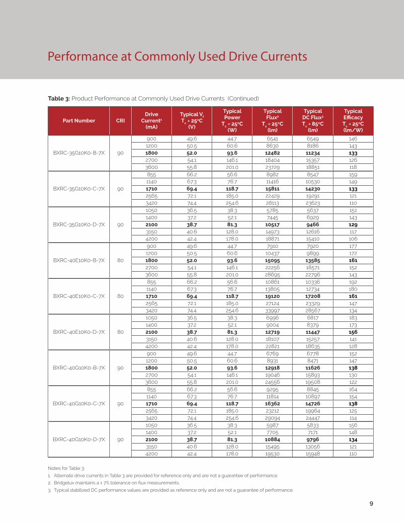
Performance at Commonly Used Drive Currents
Notes for Table 3:
1. Alternate drive currents in Table 3 are provided for reference only and are not a guarantee of performance.
2. Bridgelux maintains a ± 7% tolerance on flux measurements.
3. Typical stabilized DC performance values are provided as reference only and are not a guarantee of performance.
Table 3: Product Performance at Commonly Used Drive Currents (Continued)
Part Number CRIDrive
Current1
(mA)
Typical Vf Tc = 25ºC
(V)
Typical Power
Tc = 25ºC(W)
Typical Flux2
Tc = 25ºC(lm)
Typical DC Flux3 Tc = 85ºC
(lm)
Typical Efficacy Tc = 25ºC(lm/W)
BXRC-30E10K0-B-7X 80
900 49.6 44.7 7605 7616 1701200 50.5 60.6 10035 9518 1661800 52.0 93.6 14514 13063 1552700 54.1 146.1 21400 17857 1473600 55.8 201.0 27591 21919 137
BXRC-30E10K0-C-7X 80
855 66.2 56.6 10444 9938 1851140 67.3 76.7 13274 12244 1731710 69.4 118.7 18385 16546 1552565 72.1 185.0 26081 22431 1413420 74.4 254.6 32690 27469 128
BXRC-30E10K0-D-7X 80
1050 36.5 38.3 6929 6751 1811400 37.2 52.1 8917 8299 1712100 38.7 81.3 12597 11337 1553150 40.6 128.0 17934 15111 1404200 42.4 178.0 22603 18457 127
BXRC-30G10K0-B-7X 90
900 49.6 44.7 6313 6321 1411200 50.5 60.6 8329 7900 1381800 52.0 93.6 12047 10842 1292700 54.1 146.1 17762 14821 1223600 55.8 201.0 22901 18193 114
BXRC-30G10K0-C-7X 90
855 66.2 56.6 8668 8249 1531140 67.3 76.7 11017 10163 1441710 69.4 118.7 15259 13733 1292565 72.1 185.0 21647 18618 1173420 74.4 254.6 27132 22799 107
BXRC-30G10K0-D-7X 90
1050 36.5 38.3 5583 5440 1461400 37.2 52.1 7186 6687 1382100 38.7 81.3 10150 9135 1253150 40.6 128.0 14451 12176 1134200 42.4 178.0 18213 14872 102
BXRC-35E10K0-B-7X 80
900 49.6 44.7 7834 7844 1751200 50.5 60.6 10336 9804 1711800 52.0 93.6 14950 13455 1602700 54.1 146.1 22042 18393 1513600 55.8 201.0 28419 22577 141
BXRC-35E10K0-C-7X 80
855 66.2 56.6 10757 10236 1901140 67.3 76.7 13672 12612 1781710 69.4 118.7 18936 17042 1602565 72.1 185.0 26863 23104 1453420 74.4 254.6 33670 28293 132
BXRC-35E10K0-D-7X 80
1050 36.5 38.3 6929 6751 1811400 37.2 52.1 8917 8298 1712100 38.7 81.3 12596 11337 1553150 40.6 128.0 17933 15110 1404200 42.4 178.0 22602 18456 127
9
Notes for Table 3:
1. Alternate drive currents in Table 3 are provided for reference only and are not a guarantee of performance.
2. Bridgelux maintains a ± 7% tolerance on flux measurements.
3. Typical stabilized DC performance values are provided as reference only and are not a guarantee of performance.
Table 3: Product Performance at Commonly Used Drive Currents (Continued)
Part Number CRIDrive
Current1
(mA)
Typical Vf Tc = 25ºC
(V)
Typical Power
Tc = 25ºC(W)
Typical Flux2
Tc = 25ºC(lm)
Typical DC Flux3 Tc = 85ºC
(lm)
Typical Efficacy Tc = 25ºC(lm/W)
BXRC-35G10K0-B-7X 90
900 49.6 44.7 6541 6549 1461200 50.5 60.6 8630 8186 1431800 52.0 93.6 12482 11234 1332700 54.1 146.1 18404 15357 1263600 55.8 201.0 23729 18851 118
BXRC-35G10K0-C-7X 90
855 66.2 56.6 8982 8547 1591140 67.3 76.7 11416 10530 1491710 69.4 118.7 15811 14230 1332565 72.1 185.0 22429 19291 1213420 74.4 254.6 28113 23623 110
BXRC-35G10K0-D-7X 90
1050 36.5 38.3 5785 5637 1511400 37.2 52.1 7445 6929 1432100 38.7 81.3 10517 9466 1293150 40.6 128.0 14973 12616 1174200 42.4 178.0 18871 15410 106
BXRC-40E10K0-B-7X 80
900 49.6 44.7 7910 7920 1771200 50.5 60.6 10437 9899 1721800 52.0 93.6 15095 13585 1612700 54.1 146.1 22256 18571 1523600 55.8 201.0 28695 22796 143
BXRC-40E10K0-C-7X 80
855 66.2 56.6 10861 10336 1921140 67.3 76.7 13805 12734 1801710 69.4 118.7 19120 17208 1612565 72.1 185.0 27124 23329 1473420 74.4 254.6 33997 28567 134
BXRC-40E10K0-D-7X 80
1050 36.5 38.3 6996 6817 1831400 37.2 52.1 9004 8379 1732100 38.7 81.3 12719 11447 1563150 40.6 128.0 18107 15257 1414200 42.4 178.0 22821 18635 128
BXRC-40G10K0-B-7X 90
900 49.6 44.7 6769 6778 1521200 50.5 60.6 8931 8471 1471800 52.0 93.6 12918 11626 1382700 54.1 146.1 19046 15893 1303600 55.8 201.0 24556 19508 122
BXRC-40G10K0-C-7X 90
855 66.2 56.6 9295 8845 1641140 67.3 76.7 11814 10897 1541710 69.4 118.7 16362 14726 1382565 72.1 185.0 23212 19964 1253420 74.4 254.6 29094 24447 114
BXRC-40G10K0-D-7X 90
1050 36.5 38.3 5987 5833 1561400 37.2 52.1 7705 7171 1482100 38.7 81.3 10884 9796 1343150 40.6 128.0 15495 13056 1214200 42.4 178.0 19530 15948 110
Performance at Commonly Used Drive Currents
10
Performance at Commonly Used Drive Currents
Notes for Table 3:
1. Alternate drive currents in Table 3 are provided for reference only and are not a guarantee of performance.
2. Bridgelux maintains a ± 7% tolerance on flux measurements.
3. Typical stabilized DC performance values are provided as reference only and are not a guarantee of performance.
Table 3: Product Performance at Commonly Used Drive Currents (Continued)
Part Number CRIDrive
Current1
(mA)
Typical Vf Tc = 25ºC
(V)
Typical Power
Tc = 25ºC(W)
Typical Flux2
Tc = 25ºC(lm)
Typical DC Flux3 Tc = 85ºC
(lm)
Typical Efficacy Tc = 25ºC(lm/W)
BXRC-50C10K1-B-74 70
900 49.6 44.7 8670 8682 1941200 50.5 60.6 11440 10851 1891800 52.0 93.6 16546 14892 1772700 54.1 146.1 24396 20357 1673600 55.8 201.0 31454 24988 156
BXRC-50C10K1-C-74 70
855 66.2 56.6 11906 11329 2101140 67.3 76.7 15132 13959 1971710 69.4 118.7 20958 18863 1772565 72.1 185.0 29732 25572 1613420 74.4 254.6 37266 31314 146
BXRC-50C10K1-D-74 70
1050 36.5 38.3 7669 7472 2001400 37.2 52.1 9869 9185 1892100 38.7 81.3 13942 12547 1723150 40.6 128.0 19848 16724 1554200 42.4 178.0 25015 20427 141
BXRC-50E10K1-B-74 80
900 49.6 44.7 8150 8161 1821200 50.5 60.6 10754 10200 1781800 52.0 93.6 15553 13998 1662700 54.1 146.1 22932 19135 1573600 55.8 201.0 29567 23489 147
BXRC-50E10K1-C-74 80
855 66.2 56.6 11191 10650 1981140 67.3 76.7 14224 13121 1851710 69.4 118.7 19701 17731 1662565 72.1 185.0 27948 24038 1513420 74.4 254.6 35030 29435 138
BXRC-50E10K1-D-74 80
1050 36.5 38.3 7208 7024 1881400 37.2 52.1 9277 8634 1782100 38.7 81.3 13105 11795 1613150 40.6 128.0 18657 15720 1464200 42.4 178.0 23515 19202 132
BXRC-50G10K1-B-74 90
900 49.6 44.7 6936 6945 1551200 50.5 60.6 9152 8681 1511800 52.0 93.6 13237 11913 1412700 54.1 146.1 19517 16285 1343600 55.8 201.0 25163 19990 125
BXRC-50G10K1-C-74 90
855 66.2 56.6 9525 9064 1681140 67.3 76.7 12106 11167 1581710 69.4 118.7 16767 15090 1412565 72.1 185.0 23786 20457 1293420 74.4 254.6 29813 25051 117
BXRC-50G10K1-D-74 90
1050 36.5 38.3 6135 5978 1601400 37.2 52.1 7895 7348 1512100 38.7 81.3 11153 10038 1373150 40.6 128.0 15878 13379 1244200 42.4 178.0 20012 16342 112

Performance at Commonly Used Drive Currents
11
Notes for Table 3:
1. Alternate drive currents in Table 3 are provided for reference only and are not a guarantee of performance.
2. Bridgelux maintains a ± 7% tolerance on flux measurements.
3. Typical stabilized DC performance values are provided as reference only and are not a guarantee of performance.
Table 3: Product Performance at Commonly Used Drive Currents (Continued)
Part Number CRIDrive
Current1
(mA)
Typical Vf Tc = 25ºC
(V)
Typical Power
Tc = 25ºC(W)
Typical Flux2
Tc = 25ºC(lm)
Typical DC Flux3 Tc = 85ºC
(lm)
Typical Efficacy Tc = 25ºC(lm/W)
BXRC-57C10K1-B-74 70
900 49.6 44.7 8366 8377 1871200 50.5 60.6 11039 10470 1821800 52.0 93.6 15966 14369 1712700 54.1 146.1 23540 19643 1613600 55.8 201.0 30351 24111 151
BXRC-57C10K1-C-74 70
855 66.2 56.6 11488 10932 2031140 67.3 76.7 14601 13469 1901710 69.4 118.7 20223 18201 1702565 72.1 185.0 28689 24675 1553420 74.4 254.6 35959 30215 141
BXRC-57C10K1-D-74 70
1050 36.5 38.3 7400 7210 1931400 37.2 52.1 9523 8862 1832100 38.7 81.3 13452 12107 1663150 40.6 128.0 19152 16137 1504200 42.4 178.0 24138 19711 136
BXRC-57E10K1-B-74 80
900 49.6 44.7 8290 8301 1861200 50.5 60.6 10938 10375 1811800 52.0 93.6 15820 14238 1692700 54.1 146.1 23326 19464 1603600 55.8 201.0 30075 23892 150
BXRC-57E10K1-C-74 80
855 66.2 56.6 11384 10833 2011140 67.3 76.7 14469 13346 1891710 69.4 118.7 20039 18035 1692565 72.1 185.0 28428 24450 1543420 74.4 254.6 35632 29941 140
BXRC-57E10K1-D-74 80
1050 36.5 38.3 7332 7144 1911400 37.2 52.1 9436 8782 1812100 38.7 81.3 13330 11997 1643150 40.6 128.0 18977 15990 1484200 42.4 178.0 23918 19531 134
BXRC-65C10K1-B-74 70
900 49.6 44.7 8518 8529 1911200 50.5 60.6 11239 10661 1861800 52.0 93.6 16256 14630 1742700 54.1 146.1 23968 20000 1643600 55.8 201.0 30902 24550 154
BXRC-65C10K1-C-74 70
855 66.2 56.6 11697 11131 2071140 67.3 76.7 14867 13714 1941710 69.4 118.7 20591 18532 1742565 72.1 185.0 29210 25123 1583420 74.4 254.6 36612 30765 144
BXRC-65C10K1-D-74 70
1050 36.5 38.3 7534 7341 1971400 37.2 52.1 9696 9024 1862100 38.7 81.3 13697 12327 1693150 40.6 128.0 19500 16430 1524200 42.4 178.0 24577 20069 138

12
Performance at Commonly Used Drive Currents
Notes for Table 3:
1. Alternate drive currents in Table 3 are provided for reference only and are not a guarantee of performance.
2. Bridgelux maintains a ± 7% tolerance on flux measurements.
3. Typical stabilized DC performance values are provided as reference only and are not a guarantee of performance.
Table 3: Product Performance at Commonly Used Drive Currents (Continued)
Part Number CRIDrive
Current1
(mA)
Typical Vf Tc = 25ºC
(V)
Typical Power
Tc = 25ºC(W)
Typical Flux2
Tc = 25ºC(lm)
Typical DC Flux3 Tc = 85ºC
(lm)
Typical Efficacy Tc = 25ºC(lm/W)
BXRC-65E10K1-B-74 80
900 49.6 44.7 8442 8453 1891200 50.5 60.6 11139 10565 1841800 52.0 93.6 16111 14500 1722700 54.1 146.1 23754 19821 1633600 55.8 201.0 30627 24330 152
BXRC-65E10K1-C-74 80
855 66.2 56.6 11593 11031 2051140 67.3 76.7 14734 13591 1921710 69.4 118.7 20407 18366 1722565 72.1 185.0 28950 24899 1563420 74.4 254.6 36286 30490 143
BXRC-65E10K1-D-74 80
1050 36.5 38.3 7467 7275 1951400 37.2 52.1 9610 8943 1842100 38.7 81.3 13575 12217 1673150 40.6 128.0 19326 16284 1514200 42.4 178.0 24357 19890 137
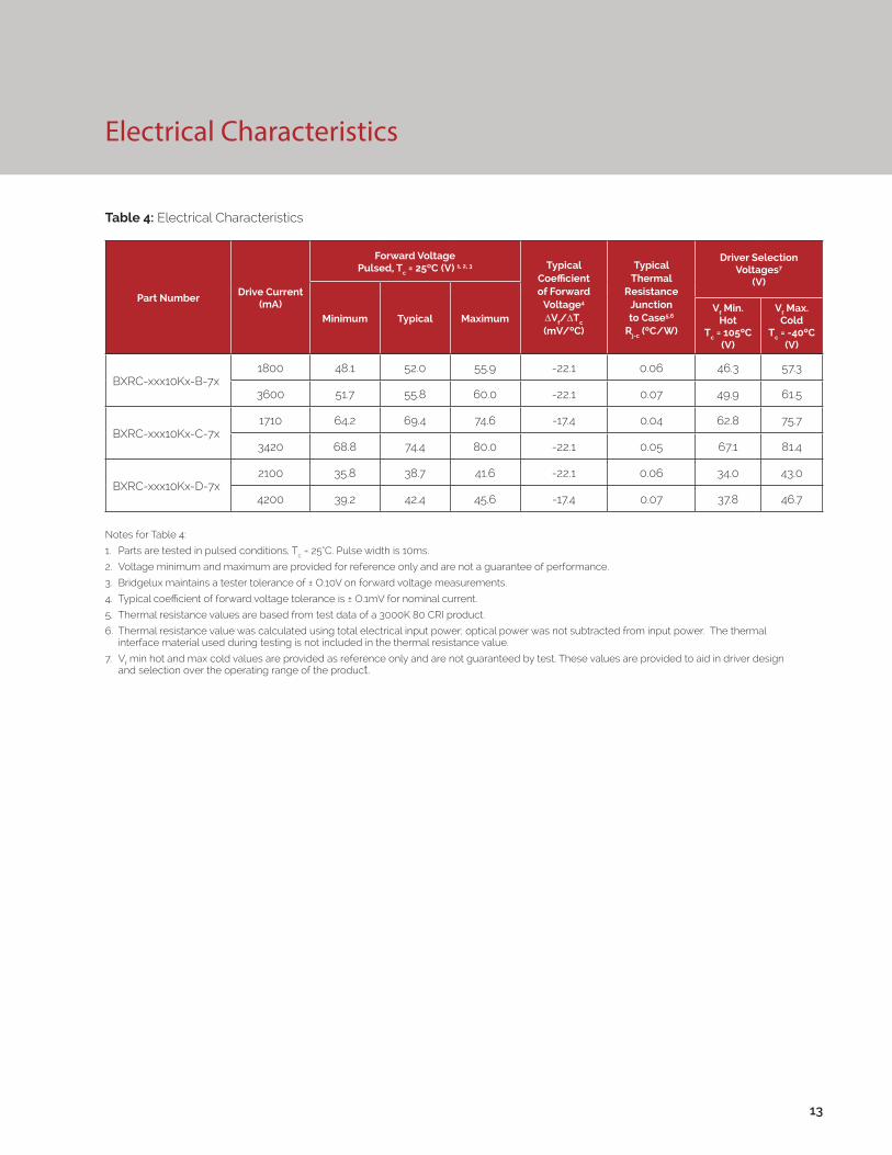
Electrical Characteristics
Notes for Table 4:
1. Parts are tested in pulsed conditions, Tc = 25°C. Pulse width is 10ms.
2. Voltage minimum and maximum are provided for reference only and are not a guarantee of performance.
3. Bridgelux maintains a tester tolerance of ± O.10V on forward voltage measurements.
4. Typical coefficient of forward voltage tolerance is ± O.1mV for nominal current.
5. Thermal resistance values are based from test data of a 3000K 80 CRI product.
6. Thermal resistance value was calculated using total electrical input power; optical power was not subtracted from input power. The thermal interface material used during testing is not included in the thermal resistance value.
7. Vf min hot and max cold values are provided as reference only and are not guaranteed by test. These values are provided to aid in driver design and selection over the operating range of the product.
Table 4: Electrical Characteristics
13
Part NumberDrive Current
(mA)
Forward VoltagePulsed, Tc = 25ºC (V) 1, 2, 3 Typical
Coefficient of Forward
Voltage4 ∆Vf/∆Tc
(mV/ºC)
Typical Thermal
Resistance Junction to Case5,6
Rj-c (ºC/W)
Driver Selection Voltages7
(V)
Minimum Typical MaximumVf Min.
Hot Tc = 105ºC
(V)
Vf Max. Cold
Tc = -40ºC (V)
BXRC-xxx10Kx-B-7x1800 48.1 52.0 55.9 -22.1 0.06 46.3 57.3
3600 51.7 55.8 60.0 -22.1 0.07 49.9 61.5
BXRC-xxx10Kx-C-7x1710 64.2 69.4 74.6 -17.4 0.04 62.8 75.7
3420 68.8 74.4 80.0 -22.1 0.05 67.1 81.4
BXRC-xxx10Kx-D-7x2100 35.8 38.7 41.6 -22.1 0.06 34.0 43.0
4200 39.2 42.4 45.6 -17.4 0.07 37.8 46.7

14
Absolute Maximum Ratings
Parameter Maximum Rating
LED Junction Temperature (Tj) 125°C
Storage Temperature -40°C to +105°C
Operating Case Temperature1 (Tc) 105°C
Soldering Temperature2 350°C or lower for a maximum of 10seconds
BXRC-xxx10Kx-B-7x BXRC-xxx10Kx-C-7x BXRC-xxx10Kx-D-7x
Maximum Drive Current3, 4 3600mA 3420mA 4200mA
Maximum Peak Pulsed Drive Current4, 5 5143mA 4886mA 6000mA
Maximum Reverse Voltage6 -90V -120V -65V
Table 5: Maximum Ratings
Notes for Table 5:
1. For IEC 62717 requirement, please consult your Bridgelux sales representative.
2. Refer to Bridgelux Application Note AN31: Assembly Considerations for Bridgelux Vero LED Arrays.
3. Arrays may be driven at higher currents however lumen maintenance may be reduced.
4. Per IEC 62031, LED Modules for General Lighting - Safety Specifications, the maximum allowable current when using the Molex Pico Connector is 3150mA.
5. Bridgelux recommends a maximum duty cycle of 10% and pulse width of 20 ms when operating LED Arrays at maximum peak pulsed current specified. Maximum peak pulsed currents indicate values where LED Arrays can be driven without catastrophic failures.
6. Light emitting diodes are not designed to be driven in reverse voltage and will not produce light under this condition. Maximum rating provided for reference only.
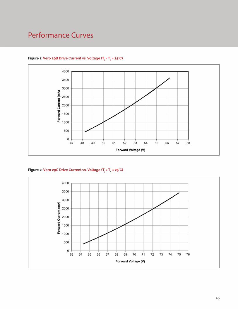
Performance Curves
Figure 1: Vero 29B Drive Current vs. Voltage (Tj = Tc = 25°C)
Figure 2: Vero 29C Drive Current vs. Voltage (Tj = Tc = 25°C)
15
0
500
1000
1500
2000
2500
3000
3500
4000
47 48 49 50 51 52 53 54 55 56 57 58
Forw
ard
Cur
rent
(mA)
Forward Voltage (V)
0
500
1000
1500
2000
2500
3000
3500
4000
63 64 65 66 67 68 69 70 71 72 73 74 75 76
Forw
ard
Cur
rent
(mA)
Forward Voltage (V)

Performance Curves
Figure 3: Vero 29D Drive Current vs. Voltage (Tj = Tc = 25°C)
Figure 4: Vero 29B Typical Relative Flux vs. Current( Tj = Tc = 25°C)
16
Note for Figure 4:
1. Bridgelux does not recommend driving high power LEDs at low currents. Doing so may produce unpredictable results. Pulse width modulation (PWM) is recommended for dimming effects.
0
500
1000
1500
2000
2500
3000
3500
4000
4500
35 36 37 38 39 40 41 42 43
Forw
ard
Cur
rent
(mA)
Forward Voltage (V)
0%
20%
40%
60%
80%
100%
120%
140%
160%
180%
200%
0 500 1000 1500 2000 2500 3000 3500 4000
Rela
tive
Lum
inou
s Flu
x
Forward Current (mA)
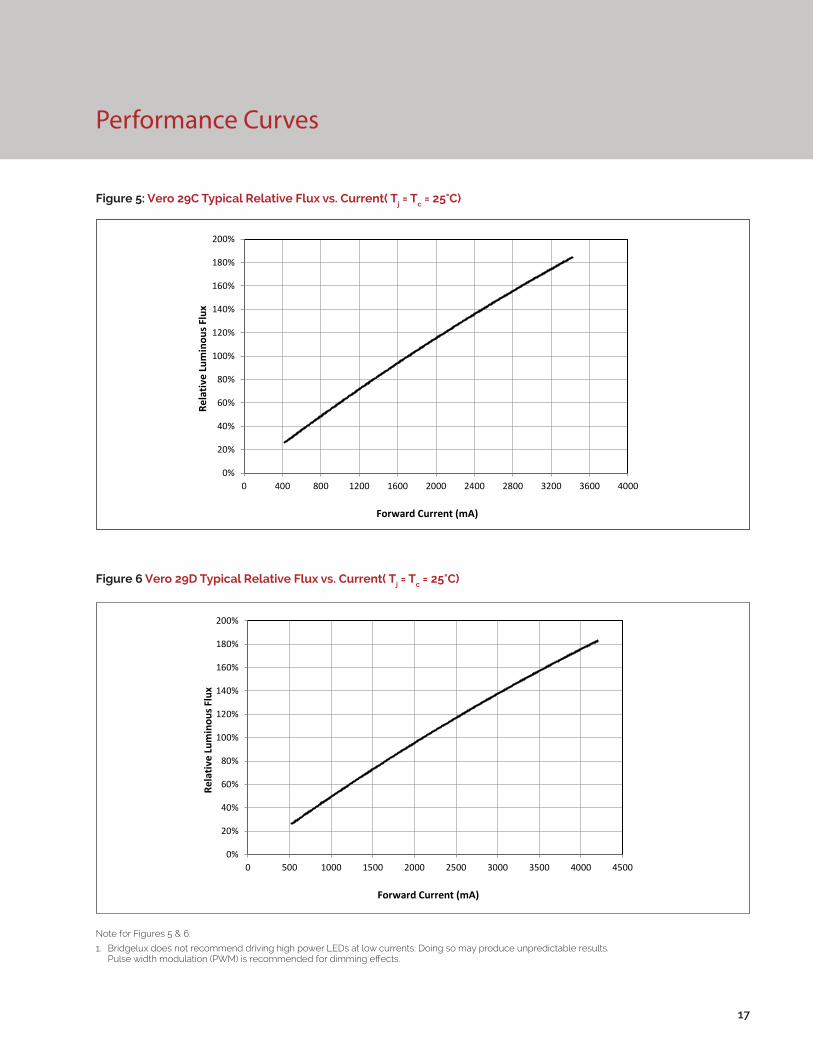
Performance Curves
Figure 5: Vero 29C Typical Relative Flux vs. Current( Tj = Tc = 25°C)
Figure 6 Vero 29D Typical Relative Flux vs. Current( Tj = Tc = 25°C)
17
Note for Figures 5 & 6:
1. Bridgelux does not recommend driving high power LEDs at low currents. Doing so may produce unpredictable results. Pulse width modulation (PWM) is recommended for dimming effects.
0%
20%
40%
60%
80%
100%
120%
140%
160%
180%
200%
0 400 800 1200 1600 2000 2400 2800 3200 3600 4000
Rela
tive
Lum
inou
s Flu
x
Forward Current (mA)
0%
20%
40%
60%
80%
100%
120%
140%
160%
180%
200%
0 500 1000 1500 2000 2500 3000 3500 4000 4500
Rela
tive
Lum
inou
s Flu
x
Forward Current (mA)
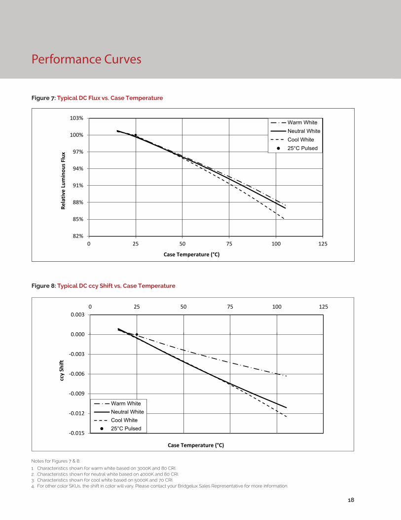
Figure 7: Typical DC Flux vs. Case Temperature
Figure 8: Typical DC ccy Shift vs. Case Temperature
18
Performance Curves
Notes for Figures 7 & 8:
1. Characteristics shown for warm white based on 3000K and 80 CRI.2. Characteristics shown for neutral white based on 4000K and 80 CRI.3. Characteristics shown for cool white based on 5000K and 70 CRI.4. For other color SKUs, the shift in color will vary. Please contact your Bridgelux Sales Representative for more information.
82%
85%
88%
91%
94%
97%
100%
103%
0 25 50 75 100 125
Rela
tive
Lum
inou
s Flu
x
Case Temperature (°C)
Warm WhiteNeutral WhiteCool White25°C Pulsed
-0.015
-0.012
-0.009
-0.006
-0.003
0.000
0.0030 25 50 75 100 125
ccy
Shift
Case Temperature (°C)
Warm WhiteNeutral WhiteCool White25°C Pulsed

Performance Curves
Figure 9: Typical DC ccx Shift vs. Case Temperature
19
Notes for Figure 9:
1. Characteristics shown for warm white based on 3000K and 80 CRI.
2. Characteristics shown for neutral white based on 4000K and 80 CRI.
3. Characteristics shown for cool white based on 5000K and 70 CRI.
4. For other color SKUs, the shift in color will vary. Please contact your Bridgelux Sales Representative for more information.
-0.012
-0.010
-0.008
-0.006
-0.004
-0.002
0.0000 25 50 75 100 125
ccx
Shift
Case Temperature (°C)
Warm WhiteNeutral WhiteCool White25°C Pulsed

Typical Radiation Pattern
Figure 10: Typical Spatial Radiation Pattern
Figure 11: Typical Polar Radiation Pattern
20
Note for Figure 10:
1. Typical viewing angle is 120⁰.
2. The viewing angle is defined as the off axis angle from the centerline where intensity is ½ of the peak value.

Typical Color Spectrum
Figure 12: Typical Color Spectrum
21
Note for Figure 12:
1. Color spectra measured at nominal current for Tj = Tc = 25°C.
2. Color spectra shown is 3000K and 80 CRI.
3. Color spectra shown is 4000K and 80 CRI.
4. Color spectra shown is 5000K and 70 CRI.
4. Color spectra shown is 6500K and 70 CRI.
0%
10%
20%
30%
40%
50%
60%
70%
80%
90%
100%
110%
400 450 500 550 600 650 700 750 800
Rela
tive
Spec
tral
Pow
er D
istr
ibut
ion
Wavelength (nm)
3000K4000K5000K6500K
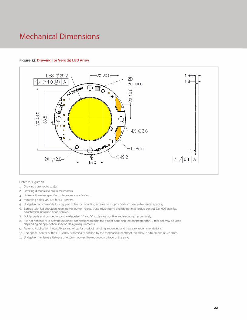
Mechanical Dimensions
Figure 13: Drawing for Vero 29 LED Array
22
Notes for Figure 10:
1. Drawings are not to scale.
2. Drawing dimensions are in millimeters.
3. Unless otherwise specified, tolerances are ± 0.10mm.
4. Mounting holes (4X) are for M3 screws.
5. Bridgelux recommends four tapped holes for mounting screws with 43.0 ± 0.10mm center-to-center spacing.
6. Screws with flat shoulders (pan, dome, button, round, truss, mushroom) provide optimal torque control. Do NOT use flat, countersink, or raised head screws.
7. Solder pads and connector port are labeled “+” and “-“ to denote positive and negative, respectively.
8. It is not necessary to provide electrical connections to both the solder pads and the connector port. Either set may be used depending on application specific design requirements.
9. Refer to Application Notes AN30 and AN31 for product handling, mounting and heat sink recommendations.
10. The optical center of the LED Array is nominally defined by the mechanical center of the array to a tolerance of ± 0.2mm.
11. Bridgelux maintains a flatness of 0.10mm across the mounting surface of the array.

Figure 14: Graph of Warm and Neutral White Test Bins in xy Color Space
Figure 15: Graph of Cool White Test Bins in xy Color Space
Color Binning Information
Bin Code 2700K 3000K 3500K 4000K
ANSI Bin(for reference only)
(2580K - 2870K) (2870K - 3220K) (3220K - 3710K) (3710K - 4260K)
23 (3 SDCM) (2651K - 2794K) (2968K - 3136K) (3369K - 3586K) (3851K - 4130K)
22 (2 SDCM) (2674K - 2769K) (2995K - 3107K) (3404K - 3548K) (3895K - 4081K)
Center Point (x,y) (0.4578, 0.4101) (0.4338, 0.403) (0.4073, 0.3917) (0.3818, 0.3797)
Table 6: Warm and Neutral White xy Bin Coordinates and Associated Typical CCT
Bin Code 5000K 5700K 6500K
ANSI Bin (for reference only) (4745K - 5311K) (5312K - 6022K) (6022K - 7042K)
4 (4 SDCM) (4801K - 5282K) (5829K - 5481K) (6270K - 6765K)
Center Point (x,y) (0.3447, 0.3553) (0.3287, 0.3417) (0.3123, 0.3282)
Table 7: Cool White xy Bin Coordinates and Associated Typical CCT (product is hot targeted to Tc = 85°C)
Note: Pulsed Test Conditions, Tc = 25°C
Note: Pulsed Test Conditions, Tc = 25°C
23

Packaging and Labeling
24
Figure 16: Drawing for Vero 29 Packaging Tray
Notes for Figure 13:
1. Dimensions are in millimeters.
2. Drawing is not to scale.
Packaging and Labeling
25
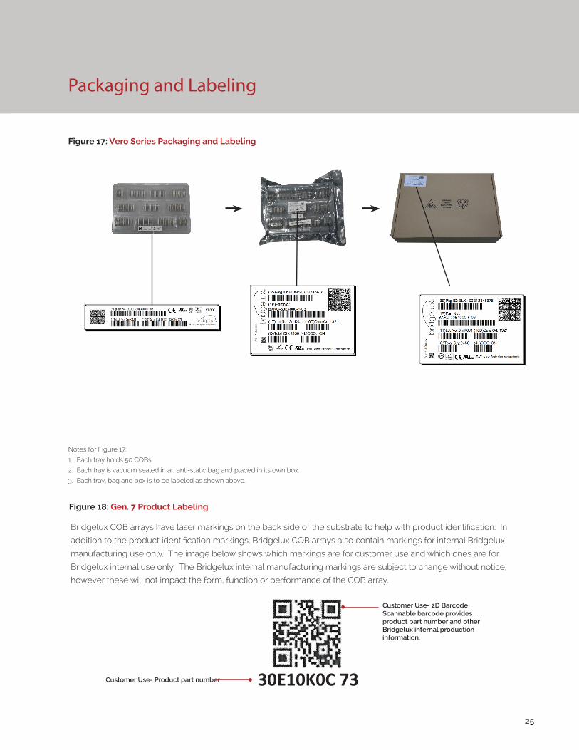
Figure 17: Vero Series Packaging and Labeling
Notes for Figure 17:
1. Each tray holds 50 COBs.
2. Each tray is vacuum sealed in an anti-static bag and placed in its own box.
3. Each tray, bag and box is to be labeled as shown above.
Figure 18: Gen. 7 Product Labeling
Bridgelux COB arrays have laser markings on the back side of the substrate to help with product identification. In
addition to the product identification markings, Bridgelux COB arrays also contain markings for internal Bridgelux
manufacturing use only. The image below shows which markings are for customer use and which ones are for
Bridgelux internal use only. The Bridgelux internal manufacturing markings are subject to change without notice,
however these will not impact the form, function or performance of the COB array.
Customer Use- 2D Barcode Scannable barcode provides product part number and other Bridgelux internal production information.
Customer Use- Product part number 30E10K0C 73

Design Resources
Disclaimers
Precautions
Application Notes
Bridgelux has developed a comprehensive set of application notes and design resources to assist customers in successfully designing with the Vero product family of LED array products. For all available application notes visit www.bridgelux.com.
Optical Source Models
Optical source models and ray set files are available for all Bridgelux products. For a list of available formats, visit www.bridgelux.com.
MINOR PRODUCT CHANGE POLICY
The rigorous qualification testing on products offered by Bridgelux provides performance assurance. Slight cosmetic changes that do not affect form, fit, or function may occur as Bridgelux continues product optimization.
CAUTION: CHEMICAL EXPOSURE HAZARD
Exposure to some chemicals commonly used in luminaire manufacturing and assembly can cause damage to the LED array. Please consult Bridgelux Application Note AN31 for additional information.
CAUTION: EYE SAFETY
Eye safety classification for the use of Bridgelux Vero Series LED arrays is in accordance with specification IEC/TR 62778: Application of IEC 62471 for the assessment of blue light hazard to light sources and luminaires. Vero Series LED arrays are classified as Risk Group 2 (Moderate Risk) when operated at or below 2.5 times the nominal drive current. The Ethr value is 889.79 lux per IEC/TR 62778. Please use appropriate precautions. Under many operating conditions the Vero Series LED arrays are classified as Risk Group 1, for more information please contact your Bridgelux sales representative. It is important that employees working with LEDs are trained to use them safely.
3D CAD Models
Three dimensional CAD models depicting the product outline of all Bridgelux Vero LED arrays are available in both IGS and STEP formats. Please contact your Bridgelux sales representative for assistance.
LM80
LM80 testing is ongoing. Please contact your Bridgelux sales representative for more information.
26
CAUTION
CONTACT WITH LIGHT EMITTING SURFACE (LES)
Avoid any contact with the LES. Do not touch the LES of the LED array or apply stress to the LES (yellow phosphor resin area). Contact may cause damage to the LED array.
Optics and reflectors must not be mounted in contact with the LES (yellow phosphor resin area). Optical devices may be mounted on the top surface of the plastic housing of the Vero LED array. Use the mechanical features of the LED array housing, edges and/or mounting holes to locate and secure optical devices as needed.
STANDARD TEST CONDITIONS
Unless otherwise stated, array testing is performed at the nominal drive current.
CAUTION: RISK OF BURN
Do not touch the Vero LED array during operation. Allow the array to cool for a sufficient period of time before handling. The Vero LED array may reach elevated temperatures such that could burn skin when touched
27
About Bridgelux: We Build Light That Transforms
© 2016 Bridgelux, Inc. All rights reserved 2016. Product specifications are subject to change without notice. Bridgelux, the Bridgelux stylized logo design and Vero are registered trademarks, and Decor Series is a trademark of Bridgelux, Inc. All other trademarks are the property of their respective owners.
Bridgelux Gen 7 Vero 29 Array Series Product Data Sheet DS93 Rev. A (06/2016)
101 Portola Avenue
Livermore, CA 94551
Tel (925) 583-8400
Fax (925) 583-8410
www.bridgelux.com
At Bridgelux, we help companies, industries and people experience the power and possibility of light. Since 2002, we’ve designed LED solutions that are high performing, energy efficient, cost effective and easy to integrate. Our focus is on light’s impact on human behavior, deliver-ing products that create better environments, experiences and returns—both experiential and financial. And our patented technology drives new platforms for commercial and industrial luminaires.
For more information about the company, please visit bridgelux.comtwitter.com/Bridgeluxfacebook.com/BridgeluxWeChat ID: BridgeluxInChina