Embed Size (px)
Citation preview
1
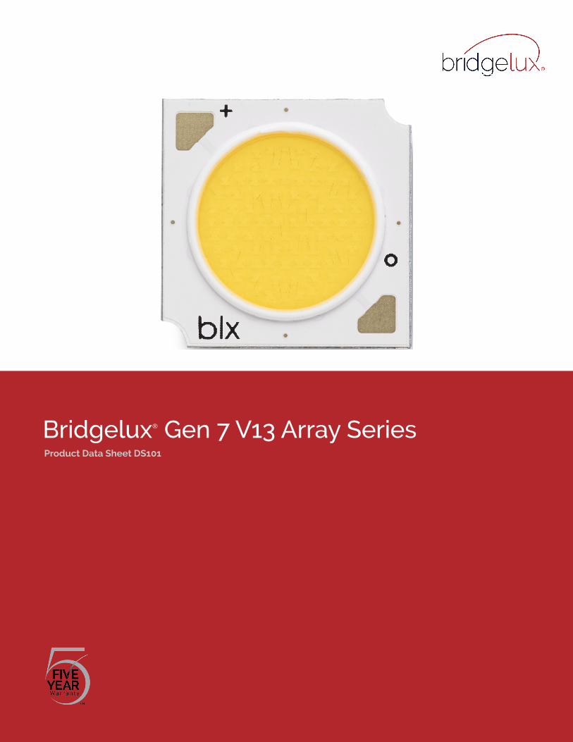
Bridgelux® Gen 7 V13 Array SeriesProduct Data Sheet DS101

Introduction
The V Series™ LED Array products deliver high quality light in a compact and cost-effective solid-state lighting package. These chip on board (CoB) arrays can be efficiently driven at twice the nominal drive current, enabling design flexibility not previously possible. This high flux density light source is designed to support a wide range of high quality, low cost directional luminaires and replacement lamps for commercial and residential applications.
The V13 LED Array is available in a variety of electrical, CCT and CRI combinations providing substantial design flexibility and energy efficiencies.
Lighting system designs incorporating these LED arrays deliver increased system level efficacy and longer service life. Typical applications include, replacement lamps, and task, accent, spot, track, wide area, security, wall pack and down lights.
Bridgelux Décor Series is our state of the art color line designed specifically for premium applications, producing unmatched LED light quality with brilliant color-rendering options and offer pleasing and inspiring lighting palettes. Bridgelux Décor Series color points are available on Vero® SE Series, Vero® Series, V Series™ and H Series™.
Décor Series Class A is based on human response testing, providing color points with a combined GAI and CRI metric.
Décor Series™ Ultra products provide a high CRI of 97 and a minimum R9 value of 93, which emphasizes the reds and color tones to which the human eye is most receptive - perfect for the most luxurious retail shops and world renowned museums. Décor Series Ultra is designed as a replacement for halogen lamps.
Décor Series™ Street and Landmark is designed to be a direct replacement for high pressure sodium lamps.
Décor Series™ Showcase is the optimal solution for replacing ceramic metal halide lamps, incorporating the same pure white light with enhanced spectrum coverage and higher efficacy.
V S
erie
s
Features
• Efficacy of 160 lm/W typical
• Compact high flux density light source
• Uniform high quality illumination
• Minimum 65, 70, 80, 90 and 95 CRI options
• Streamlined thermal path
• ENERGY STAR® / ANSI compliant color binning structure with 2, 3 and 4 SDCM options
• More energy efficient than incandescent, halogen and fluorescent lamps
• Low voltage DC operation
• Instant light with unlimited dimming
• Vf bin code backside marking
Benefits
• Enhanced optical control
• Clean white light without pixilation
• High quality true color reproduction
• Significantly reduced thermal resistance and increased operating temperatures
• Uniform consistent white light
• Lower operating costs
• Easy to use with daylight and motion detectors to enable increased energy savings
• Reduced maintenance costs
• Environmentally friendly, no disposal issue
1
Contents
Product Feature Map 2
Product Nomenclature 2
Product Selection Guide 3
Performance at Commonly Used Drive Currents 7
Electrical Characteristics 12
Eye Safety 13
Absolute Maximum Ratings 14
Performance Curves 15
Typical Radiation Pattern 18
Typical Color Spectrum 19
Mechanical Dimensions 20
Color Binning Information 21
Packaging and Labeling 22
Design Resources 24
Precautions 24
Disclaimers 24
About Bridgelux 25
2
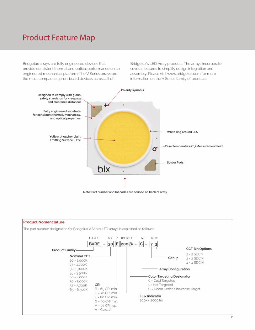
Product Feature Map
Product Nomenclature
The part number designation for Bridgelux V Series LED arrays is explained as follows:
1 2 3 4 5 6 7 8 9 10 11 – 12 – 13 14
Product Family CCT Bin Options
2 = 2 SDCM3 = 3 SDCM4 = 4 SDCM
CRIB = 65 CRI min.C = 70 CRI min.E = 80 CRI min. G = 90 CRI min.H = 97 CRI typ.A = Class A
Array Configuration
20 = 2,000K27 = 2,700K30 = 3,000K35 = 3,500K40 = 4,000K50 = 5,000K57 = 5,700K65 = 6,500K
BXRE – 30 E 200 0 – C – 7 3
Color Targeting Designator0 = Cold Targeted1 = Hot TargetedC = Décor Series Showcase Target
Gen. 7Nominal CCT
Flux Indicator200x = 2000 lm
Bridgelux arrays are fully engineered devices that provide consistent thermal and optical performance on an engineered mechanical platform. The V Series arrays are the most compact chip-on-board devices across all of
Bridgelux’s LED Array products. The arrays incorporate several features to simplify design integration and assembly. Please visit www.bridgelux.com for more information on the V Series family of products.
Fully engineered substrate for consistent thermal, mechanical
and optical properties
Yellow phosphor Light Emitting Surface (LES)
Note: Part number and lot codes are scribed on back of array
Polarity symbols
Solder Pads
White ring around LES
Case Temperature (Tc) Measurement Point
Designed to comply with global safety standards for creepage
and clearance distances
3
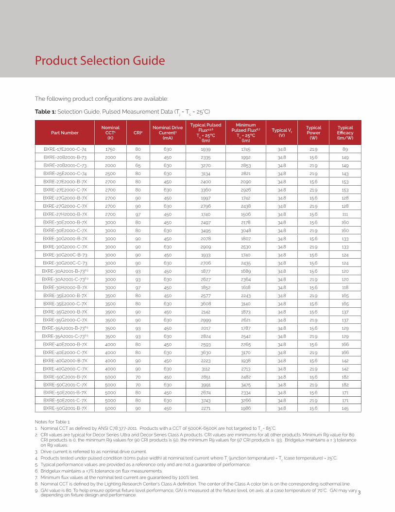
Product Selection Guide
The following product configurations are available:
Table 1: Selection Guide, Pulsed Measurement Data (Tj = Tc = 25°C)
Part NumberNominal
CCT1
(K)CRI2
Nominal Drive Current3
(mA)
Typical Pulsed Flux4,5,6
Tc = 25ºC(lm)
Minimum Pulsed Flux6,7
Tc = 25ºC(lm)
Typical Vf (V)
Typical Power
(W)
Typical Efficacy (lm/W)
BXRE-17E2000-C-74 1750 80 630 1939 1745 34.8 21.9 89
BXRE-20B2001-B-73 2000 65 450 2335 1992 34.8 15.6 149
BXRE-20B2001-C-73 2000 65 630 3270 2853 34.8 21.9 149
BXRE-25E2000-C-74 2500 80 630 3134 2821 34.8 21.9 143
BXRE-27E2000-B-7X 2700 80 450 2400 2090 34.8 15.6 153
BXRE-27E2000-C-7X 2700 80 630 3360 2926 34.8 21.9 153
BXRE-27G2000-B-7X 2700 90 450 1997 1742 34.8 15.6 128
BXRE-27G2000-C-7X 2700 90 630 2796 2438 34.8 21.9 128
BXRE-27H2000-B-7X 2700 97 450 1740 1506 34.8 15.6 111
BXRE-30E2000-B-7X 3000 80 450 2497 2178 34.8 15.6 160
BXRE-30E2000-C-7X 3000 80 630 3495 3048 34.8 21.9 160
BXRE-30G2000-B-7X 3000 90 450 2078 1807 34.8 15.6 133
BXRE-30G2000-C-7X 3000 90 630 2909 2530 34.8 21.9 133
BXRE-30G200C-B-73 3000 90 450 1933 1740 34.8 15.6 124
BXRE-30G200C-C-73 3000 90 630 2706 2435 34.8 15.6 124
BXRE-30A2001-B-738,9 3000 93 450 1877 1689 34.8 15.6 120
BXRE-30A2001-C-738,9 3000 93 630 2627 2364 34.8 21.9 120
BXRE-30H2000-B-7X 3000 97 450 1852 1618 34.8 15.6 118
BXRE-35E2000-B-7X 3500 80 450 2577 2243 34.8 21.9 165
BXRE-35E2000-C-7X 3500 80 630 3608 3140 34.8 15.6 165
BXRE-35G2000-B-7X 3500 90 450 2142 1873 34.8 15.6 137
BXRE-35G2000-C-7X 3500 90 630 2999 2621 34.8 21.9 137
BXRE-35A2001-B-738,9 3500 93 450 2017 1787 34.8 15.6 129
BXRE-35A2001-C-738,9 3500 93 630 2824 2542 34.8 21.9 129
BXRE-40E2000-B-7X 4000 80 450 2593 2265 34.8 15.6 166
BXRE-40E2000-C-7X 4000 80 630 3630 3170 34.8 21.9 166
BXRE-40G2000-B-7X 4000 90 450 2223 1938 34.8 15.6 142
BXRE-40G2000-C-7X 4000 90 630 3112 2713 34.8 21.9 142
BXRE-50C2001-B-7X 5000 70 450 2851 2482 34.8 15.6 182
BXRE-50C2001-C-7X 5000 70 630 3991 3475 34.8 21.9 182
BXRE-50E2001-B-7X 5000 80 450 2674 2334 34.8 15.6 171
BXRE-50E2001-C-7X 5000 80 630 3743 3266 34.8 21.9 171
BXRE-50G2001-B-7X 5000 90 450 2271 1986 34.8 15.6 145
Notes for Table 1:1. Nominal CCT as defined by ANSI C78.377-2011. Products with a CCT of 5000K-6500K are hot targeted to Tc = 85°C.2. CRI values are typical for Decor Series Ultra and Decor Series Class A products. CRI values are minimums for all other products. Minimum R9 value for 80
CRI products is 0, the minimum R9 values for 90 CRI products is 50, the minimum R9 values for 97 CRI products is 93. Bridgelux maintains a ± 3 tolerance on R9 values.
3. Drive current is referred to as nominal drive current. 4. Products tested under pulsed condition (10ms pulse width) at nominal test current where Tj (junction temperature) = Tc (case temperature) = 25°C. 5. Typical performance values are provided as a reference only and are not a guarantee of performance. 6. Bridgelux maintains a ±7% tolerance on flux measurements. 7. Minimum flux values at the nominal test current are guaranteed by 100% test. 8. Nominal CCT is defined by the Lighting Research Center’s Class A definition. The center of the Class A color bin is on the corresponding isothermal line.9. GAI value is 80. To help ensure optimal fixture level performance, GAI is measured at the fixture level, on axis, at a case temperature of 70°C. GAI may vary
depending on fixture design and performance.

4
Product Selection Guide
Table 1: Selection Guide, Pulsed Measurement Data (Tj = Tc = 25°C) (continued)
Part NumberNominal
CCT1
(K)CRI2
Nominal Drive Current3
(mA)
Typical Pulsed Flux4,5,6
Tc = 25ºC(lm)
Minimum Pulsed Flux6,7
Tc = 25ºC(lm)
Typical Vf (V)
Typical Power
(W)
Typical Efficacy (lm/W)
BXRE-50G2001-C-7X 5000 90 630 3179 2780 34.8 21.9 145
BXRE-57C2001-B-7X 5700 70 450 2754 2395 34.8 15.6 176
BXRE-57C2001-C-7X 5700 70 630 3856 3353 34.8 21.9 176
BXRE-57E2001-B-7X 5700 80 450 2643 2374 34.8 15.6 169
BXRE-57E2001-C-7X 5700 80 630 3700 3322 34.8 21.9 169
BXRE-65C2001-B-7X 6500 70 450 2803 2439 34.8 15.6 179
BXRE-65C2001-C-7X 6500 70 630 3924 3414 34.8 21.9 179
BXRE-65E2001-B-7X 6500 80 450 2690 2417 34.8 15.6 172
BXRE-65E2001-C-7X 6500 80 630 3766 3383 34.8 21.9 172
Notes for Table 1:1. Nominal CCT as defined by ANSI C78.377-2011. Products with a CCT of 5000K-6500K are hot targeted to Tc = 85°C.2. CRI values are typical for Decor Series Ultra and Decor Series Class A products. CRI values are minimums for all other products. Minimum R9 value for 80
CRI products is 0, the minimum R9 values for 90 CRI products is 50, the minimum R9 values for 97 CRI products is 93. Bridgelux maintains a ± 3 tolerance on R9 values.
3. Drive current is referred to as nominal drive current. 4. Products tested under pulsed condition (10ms pulse width) at nominal test current where Tj (junction temperature) = Tc (case temperature) = 25°C. 5. Typical performance values are provided as a reference only and are not a guarantee of performance. 6. Bridgelux maintains a ±7% tolerance on flux measurements. 7. Minimum flux values at the nominal test current are guaranteed by 100% test. 8. Nominal CCT is defined by the Lighting Research Center’s Class A definition. The center of the Class A color bin is on the corresponding isothermal line.9. GAI value is 80. To help ensure optimal fixture level performance, GAI is measured at the fixture level, on axis, at a case temperature of 70°C. GAI may vary
depending on fixture design and performance.
Table 2: Selection Guide, Stabilized DC Performance (Tc = 70°C) 7,8
Part NumberNominal
CCT1 (K)
GAI2 CRI3
Nominal Drive
Current4 (mA)
Typical DC Flux5,6
Tc = 70ºC(lm)
Minimum DC Flux6,9
Tc = 70ºC(lm)
Typical Vf (V)
Typical Power
(W)
Typical Efficacy (lm/W)
BXRE-30A2001-B-73 3000 80 93 450 1751 1576 34.4 15.5 113
BXRE-30A2001-C-73 3000 80 93 630 2452 2207 34.4 21.7 113
BXRE-35A2001-B-73 3500 80 93 450 1876 1688 34.4 15.5 121
BXRE-35A2001-C-73 3500 80 93 630 2622 2360 34.4 21.7 121
Notes for Table 2:
1. Nominal CCT is defined by the Lighting Research Center’s Class A definition. The center of the Class A color bin is on the corresponding isothermal line.
2. To help ensure optimal fixture level performance, GAI is measured at the fixture level, on axis, at a case temperature of 70°C. GAI may vary depending on fixture design and performance.
3. All CRI values are measured at Tj = Tc = 25°C. CRI Values are specified as typical.
4. Drive current is referred to as nominal drive current.
5. Typical performance values are provided as a reference only and are not a guarantee of performance.
6. Bridgelux maintains a ±7% tolerance on flux measurements.
7. Typical stabilized DC performance values are provided as reference only and are not a guarantee of performance.
8. Typical performance is estimated based on operation under DC (direct current) with LED array mounted onto a heat sink with thermal interface material and the case temperature maintained at specified temperature. Based on Bridgelux test setup, values may vary depending on the thermal design of the luminaire and/or the exposed environment to which the product is subjected.
9. Minimum flux values at elevated temperatures are provided for reference only and are not guaranteed by 100% production testing. Based on Bridgelux test setup, values may vary depending on the thermal design of the luminaire and/or the exposed environment to which the product is subjected.

5
Product Selection Guide
Table 3: Selection Guide, Stabilized DC Performance (Tc = 85°C) 4,5
Part Number Nominal CCT1 (K) CRI2
Nominal Drive Current3
(mA)
Typical DC Flux4,5
Tc = 85ºC(lm)
Minimum DC Flux6
Tc = 85ºC(lm)
Typical Vf (V)
Typical Power
(W)
Typical Efficacy (lm/W)
BXRE-17E2000-C-74 1750 80 630 1745 1571 33.9 21.4 82
BXRE-20B2001-B-73 2000 65 450 2102 1892 33.9 15.3 138
BXRE-20B2001-C-73 2000 65 630 2943 2648 33.9 21.4 138
BXRE-25E2000-C-74 2500 80 630 2821 2539 33.9 21.4 132
BXRE-27E2000-B-7X 2700 80 450 2160 1944 33.9 15.3 142
BXRE-27E2000-C-7X 2700 80 630 3024 2721 33.9 21.4 142
BXRE-27G2000-B-7X 2700 90 450 1797 1618 33.9 15.3 118
BXRE-27G2000-C-7X 2700 90 630 2516 2265 33.9 21.4 118
BXRE-27H2000-B-7X 2700 97 450 1566 1409 33.9 15.3 103
BXRE-30E2000-B-7X 3000 80 450 2247 2022 33.9 15.3 147
BXRE-30E2000-C-7X 3000 80 630 3146 2831 33.9 21.4 147
BXRE-30G2000-B-7X 3000 90 450 1870 1683 33.9 15.3 123
BXRE-30G2000-C-7X 3000 90 630 2618 2356 33.9 21.4 123
BXRE-30G200C-B-73 3000 90 450 1740 1566 33.9 15.3 114
BXRE-30G200C-C-73 3000 90 630 2435 2192 33.9 21.4 114
BXRE-30A2001-B-737,8 3000 93 450 1689 1520 33.9 15.3 111
BXRE-30A2001-C-737,8 3000 93 630 2364 2128 33.9 21.4 111
BXRE-30H2000-B-7X 3000 97 450 1667 1500 33.9 15.3 109
BXRE-35E2000-B-7X 3500 80 450 2319 2087 33.9 15.3 152
BXRE-35E2000-C-7X 3500 80 630 3247 2922 33.9 21.4 152
BXRE-35G2000-B-7X 3500 90 450 1928 1735 33.9 15.3 126
BXRE-35G2000-C-7X 3500 90 630 2699 2429 33.9 21.4 126
BXRE-35A2001-B-737,8 3500 93 450 1816 1634 33.9 15.3 119
BXRE-35A2001-C-737,8 3500 93 630 2542 2288 33.9 21.4 119
BXRE-40E2000-B-7X 4000 80 450 2334 2100 33.9 15.3 153
BXRE-40E2000-C-7X 4000 80 630 3267 2941 33.9 21.4 153
BXRE-40G2000-B-7X 4000 90 450 2000 1800 33.9 15.3 131
BXRE-40G2000-C-7X 4000 90 630 2801 2521 33.9 21.4 131
BXRE-50C2001-B-7X 5000 70 450 2566 2309 33.9 15.3 168
BXRE-50C2001-C-7X 5000 70 630 3592 3233 33.9 21.4 168
BXRE-50E2001-B-7X 5000 80 450 2406 2166 33.9 15.3 158
BXRE-50E2001-C-7X 5000 80 630 3369 3032 33.9 21.4 158
BXRE-50G2001-B-7X 5000 90 450 2044 1840 33.9 15.3 134
Notes for Table 3:1. Nominal CCT as defined by ANSI C78.377-2011. Products with a CCT of 5000K-6500K are hot targeted to Tc = 85°C. 2. All CRI values are measured at Tj = Tc = 25°C. CRI values are typical for Decor Series Ultra and Decor Series Class A products. CRI values are minimums for all
other products. Minimum R9 value for 80 CRI products is 0, the minimum R9 values for 90 CRI products is 50, the minimum R9 values for 97 CRI products is 93. Bridgelux maintains a ± 3 tolerance on R9 values.
3. Drive current is referred to as nominal drive current. 4. Typical stabilized DC performance values are provided as reference only and are not a guarantee of performance. 5. Typical performance is estimated based on operation under DC (direct current) with LED array mounted onto a heat sink with thermal interface
material and the case temperature maintained at 85°C. Based on Bridgelux test setup, values may vary depending on the thermal design of the luminaire and/or the exposed environment to which the product is subjected.
6. Minimum flux values at elevated temperatures are provided for reference only and are not guaranteed by 100% production testing. Based on Bridgelux test setup, values may vary depending on the thermal design of the luminaire and/or the exposed environment to which the product is subjected.
7. Nominal CCT is defined by the Lighting Research Center’s Class A definition. The center of the Class A color bin is on the corresponding isothermal line.8. GAI value is 80. To help ensure optimal fixture level performance, GAI is measured at the fixture level, on axis, at a case temperature of 70°C. GAI may vary
depending on fixture design and performance.

6
Product Selection Guide
Table 3: Selection Guide, Stabilized DC Performance (Tc = 85°C) 4,5 (continued)
Part Number Nominal CCT1 (K) CRI2
Nominal Drive Current3
(mA)
Typical DC Flux4,5
Tc = 85ºC(lm)
Minimum DC Flux6
Tc = 85ºC(lm)
Typical Vf (V)
Typical Power
(W)
Typical Efficacy (lm/W)
BXRE-50G2001-C-7X 5000 90 630 2862 2575 33.9 21.4 134
BXRE-57C2001-B-7X 5700 70 450 2479 2231 33.9 15.3 162
BXRE-57C2001-C-7X 5700 70 630 3470 3123 33.9 21.4 162
BXRE-57E2001-B-7X 5700 80 450 2378 2141 33.9 15.3 156
BXRE-57E2001-C-7X 5700 80 630 3330 2997 33.9 21.4 156
BXRE-65C2001-B-7X 6500 70 450 2522 2270 33.9 15.3 165
BXRE-65C2001-C-7X 6500 70 630 3531 3178 33.9 21.4 165
BXRE-65E2001-B-7X 6500 80 450 2421 2179 33.9 15.3 159
BXRE-65E2001-C-7X 6500 80 630 3389 3050 33.9 21.4 159
Notes for Table 3:1. Nominal CCT as defined by ANSI C78.377-2011. Products with a CCT of 5000K-6500K are hot targeted to Tc = 85°C. 2. All CRI values are measured at Tj = Tc = 25°C. CRI values are typical for Decor Series Ultra and Decor Series Class A products. CRI values are minimums
for all other products. Minimum R9 value for 80 CRI products is 0, the minimum R9 values for 90 CRI products is 50, the minimum R9 values for 97 CRI products is 93. Bridgelux maintains a ± 3 tolerance on R9 values.
3. Drive current is referred to as nominal drive current. 4. Typical stabilized DC performance values are provided as reference only and are not a guarantee of performance. 5. Typical performance is estimated based on operation under DC (direct current) with LED array mounted onto a heat sink with thermal interface
material and the case temperature maintained at 85°C. Based on Bridgelux test setup, values may vary depending on the thermal design of the luminaire and/or the exposed environment to which the product is subjected.
6. Minimum flux values at elevated temperatures are provided for reference only and are not guaranteed by 100% production testing. Based on Bridgelux test setup, values may vary depending on the thermal design of the luminaire and/or the exposed environment to which the product is subjected.
7. Nominal CCT is defined by the Lighting Research Center’s Class A definition. The center of the Class A color bin is on the corresponding isothermal line.8. GAI value is 80. To help ensure optimal fixture level performance, GAI is measured at the fixture level, on axis, at a case temperature of 70°C. GAI may
vary depending on fixture design and performance.

7
Performance at Commonly Used Drive Currents
V Series LED arrays are tested to the specifications shown using the nominal drive currents in Table 1. V Series may also
be driven at other drive currents dependent on specific application design requirements. The performance at any
drive current can be derived from the current vs. voltage characteristics shown in Figures 1 & 2 and the flux vs. current
characteristics shown in Figures 3 & 4. The performance at commonly used drive currents is summarized in Table 4.
Table 4: Product Performance at Commonly Used Drive Currents
Part Number CRIDrive
Current1
(mA)
Typical Vf Tc = 25ºC
(V)
Typical Power
Tc = 25ºC(W)
Typical Flux2
Tc = 25ºC(lm)
Typical DC Flux3 Tc = 85ºC
(lm)
Typical Efficacy Tc = 25ºC(lm/W)
BXRE-17E2000-C-74 80
158 32.3 5.1 527 499 104315 33.2 10.4 1018 959 97630 34.8 21.9 1939 1745 89945 36.1 34.1 2787 2606 821260 37.3 47.0 3556 3314 76
BXRE-20B2001-B-7x 65
113 32.3 3.6 640 591 176225 33.2 7.5 1235 1133 165450 34.8 15.6 2335 1992 149675 36.0 24.3 3379 3067 139900 37.2 33.5 4309 3892 129
BXRE-20B2001-C-73 65
158 32.3 5.1 889 842 175315 33.2 10.4 1716 1617 164630 34.8 21.9 3270 2853 149945 36.1 34.1 4698 4394 1381260 37.3 47.0 5995 5588 128
BXRE-25E2000-C-74 80
158 32.3 5.1 852 807 167315 33.2 10.4 1645 1550 157630 34.8 21.9 3134 2821 143945 36.1 34.1 4504 4212 1321260 37.3 47.0 5747 5357 122
BXRE-27E2000-B-7x 80
113 32.3 3.6 658 607 181225 33.2 7.5 1269 1165 170450 34.8 15.6 2400 2160 153675 36.0 24.3 3472 3152 143900 37.2 33.5 4428 3999 132
BXRE-27E2000-C-7x 80
158 32.3 5.1 914 865 179315 33.2 10.4 1763 1662 169630 34.8 21.9 3360 3024 153945 36.1 34.1 4828 4515 1421260 37.3 47.0 6161 5742 131
BXRE-27G2000-B-7x 90
113 32.3 3.6 547 505 151225 33.2 7.5 1056 969 142450 34.8 15.6 1997 1797 128675 36.0 24.3 2890 2623 119900 37.2 33.5 3685 3328 110
BXRE-27G2000-C-7x 90
158 32.3 5.1 760 720 149315 33.2 10.4 1467 1383 140630 34.8 21.9 2796 2516 128945 36.1 34.1 4018 3758 1181260 37.3 47.0 5127 4778 109
Notes for Table 4:1. Alternate drive currents are provided for reference only and are not a guarantee of performance.2. Bridgelux maintains a ± 7% tolerance on flux measurements.3. Typical stabilized DC performance values are provided as reference only and are not a guarantee of performance.
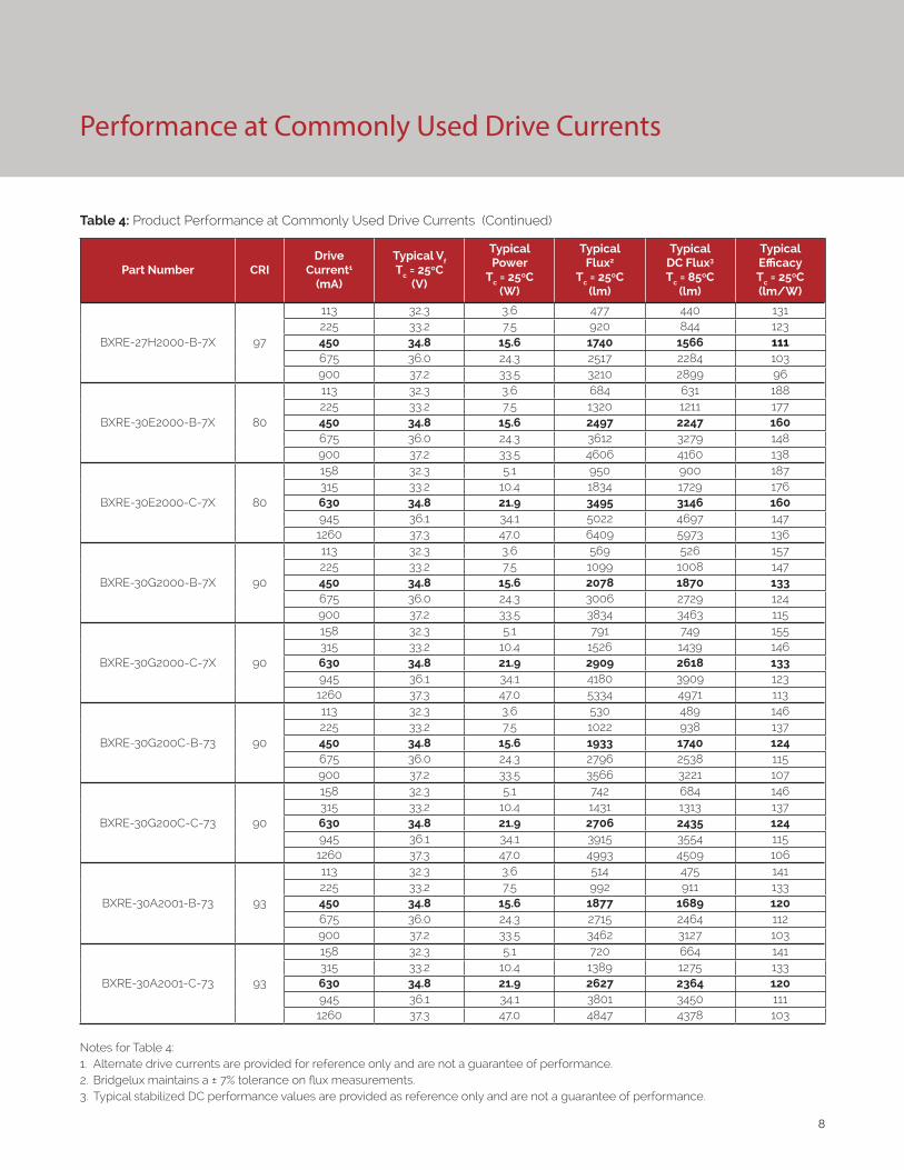
8
Performance at Commonly Used Drive Currents
Table 4: Product Performance at Commonly Used Drive Currents (Continued)
Part Number CRIDrive
Current1
(mA)
Typical Vf Tc = 25ºC
(V)
Typical Power
Tc = 25ºC(W)
Typical Flux2
Tc = 25ºC(lm)
Typical DC Flux3 Tc = 85ºC
(lm)
Typical Efficacy Tc = 25ºC(lm/W)
BXRE-27H2000-B-7X 97
113 32.3 3.6 477 440 131225 33.2 7.5 920 844 123450 34.8 15.6 1740 1566 111675 36.0 24.3 2517 2284 103900 37.2 33.5 3210 2899 96
BXRE-30E2000-B-7X 80
113 32.3 3.6 684 631 188225 33.2 7.5 1320 1211 177450 34.8 15.6 2497 2247 160675 36.0 24.3 3612 3279 148900 37.2 33.5 4606 4160 138
BXRE-30E2000-C-7X 80
158 32.3 5.1 950 900 187315 33.2 10.4 1834 1729 176630 34.8 21.9 3495 3146 160945 36.1 34.1 5022 4697 1471260 37.3 47.0 6409 5973 136
BXRE-30G2000-B-7X 90
113 32.3 3.6 569 526 157225 33.2 7.5 1099 1008 147450 34.8 15.6 2078 1870 133675 36.0 24.3 3006 2729 124900 37.2 33.5 3834 3463 115
BXRE-30G2000-C-7X 90
158 32.3 5.1 791 749 155315 33.2 10.4 1526 1439 146630 34.8 21.9 2909 2618 133945 36.1 34.1 4180 3909 1231260 37.3 47.0 5334 4971 113
BXRE-30G200C-B-73 90
113 32.3 3.6 530 489 146225 33.2 7.5 1022 938 137450 34.8 15.6 1933 1740 124675 36.0 24.3 2796 2538 115900 37.2 33.5 3566 3221 107
BXRE-30G200C-C-73 90
158 32.3 5.1 742 684 146315 33.2 10.4 1431 1313 137630 34.8 21.9 2706 2435 124945 36.1 34.1 3915 3554 1151260 37.3 47.0 4993 4509 106
BXRE-30A2001-B-73 93
113 32.3 3.6 514 475 141225 33.2 7.5 992 911 133450 34.8 15.6 1877 1689 120675 36.0 24.3 2715 2464 112900 37.2 33.5 3462 3127 103
BXRE-30A2001-C-73 93
158 32.3 5.1 720 664 141315 33.2 10.4 1389 1275 133630 34.8 21.9 2627 2364 120945 36.1 34.1 3801 3450 1111260 37.3 47.0 4847 4378 103
Notes for Table 4:1. Alternate drive currents are provided for reference only and are not a guarantee of performance.2. Bridgelux maintains a ± 7% tolerance on flux measurements.3. Typical stabilized DC performance values are provided as reference only and are not a guarantee of performance.

9
Table 4: Product Performance at Commonly Used Drive Currents (Continued)
Part Number CRIDrive
Current1
(mA)
Typical Vf Tc = 25ºC
(V)
Typical Power
Tc = 25ºC(W)
Typical Flux2
Tc = 25ºC(lm)
Typical DC Flux3 Tc = 85ºC
(lm)
Typical Efficacy Tc = 25ºC(lm/W)
BXRE-30H2000-B-7X 97
113 32.3 3.6 508 469 140225 33.2 7.5 980 899 131450 34.8 15.6 1852 1667 118675 36.0 24.3 2680 2432 110900 37.2 33.5 3418 3087 102
BXRE-35E2000-B-7X 80
113 32.3 3.6 706 652 194225 33.2 7.5 1363 1251 183450 34.8 15.6 2577 2319 165675 36.0 24.3 3729 3384 153900 37.2 33.5 4755 4295 142
BXRE-35E2000-C-7X 80
158 32.3 5.1 981 929 193315 33.2 10.4 1893 1785 181630 34.8 21.9 3608 3247 165945 36.1 34.1 5185 4849 1521260 37.3 47.0 6615 6166 141
BXRE-35G2000-B-7X 90
113 32.3 3.6 587 542 161225 33.2 7.5 1133 1039 152450 34.8 15.6 2142 1928 137675 36.0 24.3 3099 2813 127900 37.2 33.5 3953 3570 118
BXRE-35G2000-C-7X 90
158 32.3 5.1 815 772 160315 33.2 10.4 1574 1483 151630 34.8 21.9 2999 2699 137945 36.1 34.1 4310 4030 1261260 37.3 47.0 5499 5125 117
BXRE-35A2001-B-73 93
113 32.3 3.6 553 510 152225 33.2 7.5 1067 979 143450 34.8 15.6 2017 1816 129675 36.0 24.3 2919 2649 120900 37.2 33.5 3722 3362 111
BXRE-35A2001-C-73 93
158 32.3 5.1 768 727 151315 33.2 10.4 1482 1397 142630 34.8 21.9 2824 2542 129945 36.1 34.1 4058 3795 1191260 37.3 47.0 5178 4826 110
BXRE-40E2000-B-7X 80
113 32.3 3.6 711 656 195225 33.2 7.5 1371 1258 184450 34.8 15.6 2593 2334 166675 36.0 24.3 3752 3405 154900 37.2 33.5 4785 4322 143
BXRE-40E2000-C-7X 80
158 32.3 5.1 987 935 194315 33.2 10.4 1905 1796 182630 34.8 21.9 3630 3267 166945 36.1 34.1 5217 4879 1531260 37.3 47.0 6657 6204 142
Notes for Table 4:1. Alternate drive currents are provided for reference only and are not a guarantee of performance.2. Bridgelux maintains a ± 7% tolerance on flux measurements.3. Typical stabilized DC performance values are provided as reference only and are not a guarantee of performance.
Performance at Commonly Used Drive Currents
10
Performance at Commonly Used Drive Currents
Table 4: Product Performance at Commonly Used Drive Currents (Continued)
Part Number CRIDrive
Current1
(mA)
Typical Vf Tc = 25ºC
(V)
Typical Power
Tc = 25ºC(W)
Typical Flux2
Tc = 25ºC(lm)
Typical DC Flux3 Tc = 85ºC
(lm)
Typical Efficacy Tc = 25ºC(lm/W)
BXRE-40G2000-B-7X 90
113 32.3 3.6 609 562 168225 33.2 7.5 1175 1079 158450 34.8 15.6 2223 2000 142675 36.0 24.3 3216 2919 132900 37.2 33.5 4101 3704 123
BXRE-40G2000-C-7X 90
158 32.3 5.1 846 801 166315 33.2 10.4 1633 1539 156630 34.8 21.9 3112 2801 142945 36.1 34.1 4472 4182 1311260 37.3 47.0 5706 5318 121
BXRE-50C2001-B-7X 70
113 32.3 3.6 781 721 215225 33.2 7.5 1508 1383 202450 34.8 15.6 2851 2566 182675 36.0 24.3 4125 3744 170900 37.2 33.5 5260 4751 157
BXRE-50C2001-C-7X 70
158 32.3 5.1 1085 1028 213315 33.2 10.4 2094 1974 200630 34.8 21.9 3991 3592 182945 36.1 34.1 5735 5364 1681260 37.3 47.0 7318 6821 156
BXRE-50E2001-B-7X 80
113 32.3 3.6 733 676 201225 33.2 7.5 1414 1297 189450 34.8 15.6 2674 2406 171675 36.0 24.3 3868 3511 159900 37.2 33.5 4933 4456 147
BXRE-50E2001-C-7X 80
158 32.3 5.1 1018 964 200315 33.2 10.4 1964 1852 188630 34.8 21.9 3743 3369 171945 36.1 34.1 5379 5030 1581260 37.3 47.0 6863 6397 146
BXRE-50G2001-B-7X 90
113 32.3 3.6 622 574 171225 33.2 7.5 1201 1102 161450 34.8 15.6 2271 2044 145675 36.0 24.3 3286 2982 135900 37.2 33.5 4190 3785 125
BXRE-50G2001-C-7X 90
158 32.3 5.1 864 819 170315 33.2 10.4 1668 1573 160630 34.8 21.9 3179 2862 145945 36.1 34.1 4569 4273 1341260 37.3 47.0 5830 5434 124
BXRE-57C2001-B-7X 70
113 32.3 3.6 755 697 208225 33.2 7.5 1457 1336 195450 34.8 15.6 2754 2479 176675 36.0 24.3 3985 3617 164900 37.2 33.5 5082 4590 152
Notes for Table 4:1. Alternate drive currents are provided for reference only and are not a guarantee of performance.2. Bridgelux maintains a ± 7% tolerance on flux measurements.3. Typical stabilized DC performance values are provided as reference only and are not a guarantee of performance.

11
Performance at Commonly Used Drive Currents
Table 4: Product Performance at Commonly Used Drive Currents (Continued)
Part Number CRIDrive
Current1
(mA)
Typical Vf Tc = 25ºC
(V)
Typical Power
Tc = 25ºC(W)
Typical Flux2
Tc = 25ºC(lm)
Typical DC Flux3 Tc = 85ºC
(lm)
Typical Efficacy Tc = 25ºC(lm/W)
BXRE-57C2001-C-7X 70
158 32.3 5.1 1048 993 206315 33.2 10.4 2023 1907 194630 34.8 21.9 3856 3470 176945 36.1 34.1 5541 5182 1621260 37.3 47.0 7070 6590 150
BXRE-57E2001-B-7X 80
113 32.3 3.6 724 668 199225 33.2 7.5 1398 1282 187450 34.8 15.6 2643 2378 169675 36.0 24.3 3824 3471 157900 37.2 33.5 4876 4404 146
BXRE-57E2001-C-7X 80
158 32.3 5.1 1006 953 198315 33.2 10.4 1942 1830 186630 34.8 21.9 3700 3330 169945 36.1 34.1 5317 4972 1561260 37.3 47.0 6784 6323 144
BXRE-65C2001-B-7X 70
113 32.3 3.6 768 709 211225 33.2 7.5 1482 1360 199450 34.8 15.6 2803 2522 179675 36.0 24.3 4055 3680 167900 37.2 33.5 5171 4670 155
BXRE-65C2001-C-7X 70
158 32.3 5.1 1067 1010 210315 33.2 10.4 2059 1941 197630 34.8 21.9 3924 3531 179945 36.1 34.1 5638 5273 1651260 37.3 47.0 7194 6705 153
BXRE-65E2001-B-7X 80
113 32.3 3.6 737 680 203225 33.2 7.5 1422 1305 191450 34.8 15.6 2690 2421 172675 36.0 24.3 3892 3532 160900 37.2 33.5 4963 4482 148
BXRE-65E2001-C-7X 80
158 32.3 5.1 1024 970 201315 33.2 10.4 1976 1863 189630 34.8 21.9 3766 3389 172945 36.1 34.1 5411 5060 1591260 37.3 47.0 6904 6435 147
Notes for Table 4:1. Alternate drive currents are provided for reference only and are not a guarantee of performance.2. Bridgelux maintains a ± 7% tolerance on flux measurements.3. Typical stabilized DC performance values are provided as reference only and are not a guarantee of performance.

12
Electrical Characteristics
Table 5: Electrical Characteristics
Part NumberDrive Current
(mA)
Forward VoltagePulsed, Tc = 25ºC (V) 1, 2, 3, 8 Typical
Coefficient of Forward
Voltage4 ∆Vf/∆Tc
(mV/ºC)
Typical Thermal
Resistance Junction to Case5,6
Rj-c (ºC/W)
Driver Selection Voltages7
(V)
Minimum Typical MaximumVf Min.
Hot Tc = 105ºC
(V)
Vf Max. Cold
Tc = -40ºC (V)
BXRE-xxx200x-B-7x450 32.1 34.8 37.4 -14.1 0.28 31.0 38.3
900 34.4 37.2 40.0 -14.1 0.34 33.3 40.9
BXRE-xxx200x-C-7x630 32.1 34.8 37.4 -14.1 0.20 31.0 38.3
1260 34.5 37.3 40.1 -14.1 0.24 33.4 41.0
Notes for Table 5:
1. Parts are tested in pulsed conditions, Tc = 25°C. Pulse width is 10ms.
2. Voltage minimum and maximum are provided for reference only and are not a guarantee of performance.
3. Bridgelux maintains a tester tolerance of ± 0.10V on forward voltage measurements.
4. Typical coefficient of forward voltage tolerance is ± 0.1mV for nominal current.
5. Thermal resistance values are based from test data of a 3000K 80 CRI product.
6. Thermal resistance value was calculated using total electrical input power; optical power was not subtracted from input power. The thermal interface material used during testing is not included in the thermal resistance value.
7. Vf min hot and max cold values are provided as reference only and are not guaranteed by test. These values are provided to aid in driver design and selec-tion over the operating range of the product.
8. This product has been designed and manufactured per IEC 62031:2014. This product has passed dielectric withstand voltage testing at 1160 V. The working voltage designated for the insulation is 80V d.c. The maximum allowable voltage across the array must be determined in the end product application.
13
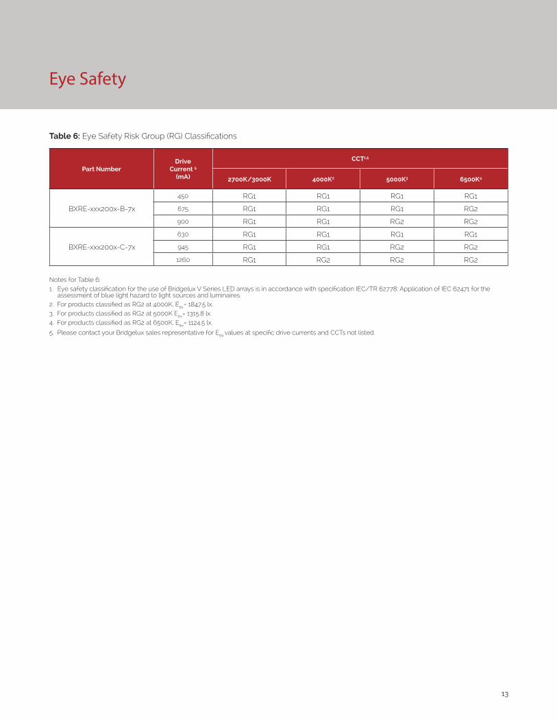
Eye Safety
Table 6: Eye Safety Risk Group (RG) Classifications
Part NumberDrive
Current 5
(mA)
CCT1,5
2700K/3000K 4000K2 5000K3 6500K4
BXRE-xxx200x-B-7x
450 RG1 RG1 RG1 RG1
675 RG1 RG1 RG1 RG2
900 RG1 RG1 RG2 RG2
BXRE-xxx200x-C-7x
630 RG1 RG1 RG1 RG1
945 RG1 RG1 RG2 RG2
1260 RG1 RG2 RG2 RG2
Notes for Table 6:1. Eye safety classification for the use of Bridgelux V Series LED arrays is in accordance with specification IEC/TR 62778: Application of IEC 62471 for the
assessment of blue light hazard to light sources and luminaires.2. For products classified as RG2 at 4000K, Ethr= 1847.5 lx.3. For products classified as RG2 at 5000K Ethr= 1315.8 lx.4. For products classified as RG2 at 6500K, Ethr= 1124.5 lx.
5. Please contact your Bridgelux sales representative for Ethr values at specific drive currents and CCTs not listed.

14
Absolute Maximum Ratings
Table 7: Maximum Ratings
Parameter Maximum Rating
LED Junction Temperature (Tj) 125°C
Storage Temperature -40°C to +105°C
Operating Case Temperature1 (Tc) 105°C
Soldering Temperature2 300°C or lower for a maximum of 6 seconds
BXRE-xxx200x-B-7x BXRE-xxx200x-C-7x
Maximum Drive Current3 900mA 1260mA
Maximum Peak Pulsed Drive Current4 1290mA 1800mA
Maximum Reverse Voltage5 -60V -60V
Notes for Table 7:
1. For IEC 62717 requirement, please consult your Bridgelux sales representative.
2. Refer to Bridgelux Application Note AN101: Handling and Assembly of Bridgelux V Series LED Arrays
3. Arrays may be driven at higher currents however lumen maintenance may be reduced.
4. Bridgelux recommends a maximum duty cycle of 10% and pulse width of 20 ms when operating LED Arrays at maximum peak pulsed current specified. Maximum peak pulsed currents indicate values where LED Arrays can be driven without catastrophic failures.
5. Light emitting diodes are not designed to be driven in reverse voltage and will not produce light under this condition. Maximum rating provided for reference only.

15
Performance Curves
Figure 3: V13B Drive Current vs. Voltage Figure 4: V13C Typical Relative Flux vs. Current
Notes for Figures 1-4:
1. Bridgelux does not recommend driving high power LEDs at low currents. Doing so may produce unpredictable results. Pulse width modulation (PWM) is recommended for dimming effects.
2. Products tested under pulsed condition (10ms pulse width) at nominal test current where Tj (junction temperature) = Tc (case temperature) = 25°C.
Figure 1: V13B Drive Current vs. Voltage Figure 2: V13C Drive Current vs. Voltage
0
100
200
300
400
500
600
700
800
900
1000
32 33 34 35 36 37 38
Forw
ard
Cur
rent
(mA)
Forward Voltage (V)
100
250
400
550
700
850
1000
1150
1300
32 33 34 35 36 37 38
Forw
ard
Cur
rent
(mA)
Forward Voltage (V)
0%
20%
40%
60%
80%
100%
120%
140%
160%
180%
200%
0 100 200 300 400 500 600 700 800 900 1000
Rela
tive
Lum
inou
s Flu
x
Forward Current (mA)
0%
20%
40%
60%
80%
100%
120%
140%
160%
180%
200%
100 250 400 550 700 850 1000 1150 1300
Rela
tive
Lum
inou
s Flu
x
Forward Current (mA)
16
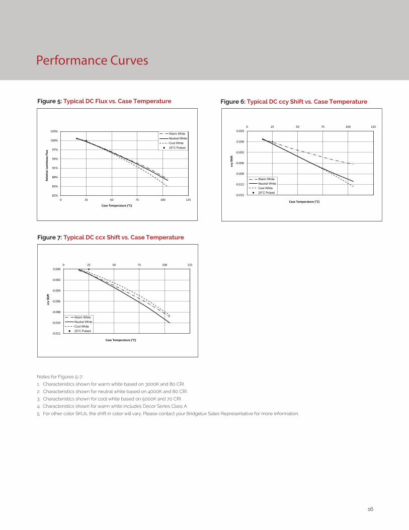
Performance Curves
Figure 5: Typical DC Flux vs. Case Temperature
82%
85%
88%
91%
94%
97%
100%
103%
0 25 50 75 100 125
Rela
tive
Lum
inou
s Flu
x
Case Temperature (°C)
Warm WhiteNeutral WhiteCool White25°C Pulsed
Notes for Figures 5-7:
1. Characteristics shown for warm white based on 3000K and 80 CRI.
2. Characteristics shown for neutral white based on 4000K and 80 CRI.
3. Characteristics shown for cool white based on 5000K and 70 CRI.
4. Characteristics shown for warm white includes Decor Series Class A
5. For other color SKUs, the shift in color will vary. Please contact your Bridgelux Sales Representative for more information.
Figure 7: Typical DC ccx Shift vs. Case Temperature
Figure 6: Typical DC ccy Shift vs. Case Temperature
-0.012
-0.010
-0.008
-0.006
-0.004
-0.002
0.0000 25 50 75 100 125
ccx
Shift
Case Temperature (°C)
Warm WhiteNeutral WhiteCool White25°C Pulsed
-0.015
-0.012
-0.009
-0.006
-0.003
0.000
0.0030 25 50 75 100 125
ccy
Shift
Case Temperature (°C)
Warm WhiteNeutral WhiteCool White25°C Pulsed

17
Figure 6: Typical DC ccy Shift vs. Case Temperature
Performance Curves
Figure 10: 2700K, 97 CRI Color Shift vs. Case Temperature1 Figure 11: 3000K, 97 CRI Color Shift vs. Case Temperature1
Figure 13: 3500K Class A Color Shift vs. Case Temperature1
0.358
0.36
0.362
0.364
0.366
0.368
0.37
0.392 0.393 0.394 0.395 0.396 0.397
ccy
ccx
PulsedCenter Point Tc=25°C
15°C
45°C
85°C
105°C
70°C
25°C
15°C
25°C
45°C
65°C
85°C
105°C
Pulsed Center Point
Tc = 25°C
0.4030
0.4040
0.4050
0.4060
0.4070
0.4080
0.4090
0.4100
0.4110
0.457 0.4572 0.4574 0.4576 0.4578 0.458
ccy
ccx
15°C
25°C
45°C
70°C
85°C
105°C
Pulsed Center Point
Tc = 25°C
0.3950
0.3970
0.3990
0.4010
0.4030
0.4050
0.4323 0.4328 0.4333 0.4338 0.4343 0.4348 0.4353
ccy
ccx
Figure 9: 3000K, 90 CRI Color Shift vs. Case Temperature1,3 Figure 8: 2000K, 65 CRI Color Shift vs. Case Temperature
Pulsed Center Point Tc=25°C
15°C
25°C
45°C
65°C
85°C
105°C
0.395
0.396
0.397
0.398
0.399
0.4
0.401
0.402
0.403
0.444 0.4445 0.445 0.4455 0.446 0.4465 0.447
ccy
ccx
105°C
85°C
65°C
45°C
25°C
15°C
Pulsed Center Point Tc=25°C
0.409
0.4091
0.4092
0.4093
0.4094
0.4095
0.4096
0.4097
0.4098
0.4099
0.41
0.4101
0.525 0.526 0.527 0.528 0.529 0.53 0.531 0.532
ccy
ccx
Note for Figures 8-12:
1. Measurements made under DC test conditions at the nominal drive current.
2. Typical color shift is shown with a tolerance of ±0.002.3. Characteristics shown for Decor Series Showcase products, BXRE-30G200C-x-73
Figure 12: 3000K Class A Color Shift vs. Case Temperature1
0.36
0.361
0.362
0.363
0.364
0.365
0.366
0.367
0.368
0.369
0.416 0.4165 0.417 0.4175 0.418 0.4185
ccy
ccx
PulsedCenter Point Tc=25°C25°C
45°C
85°C
105°C
70°C
15°C
18
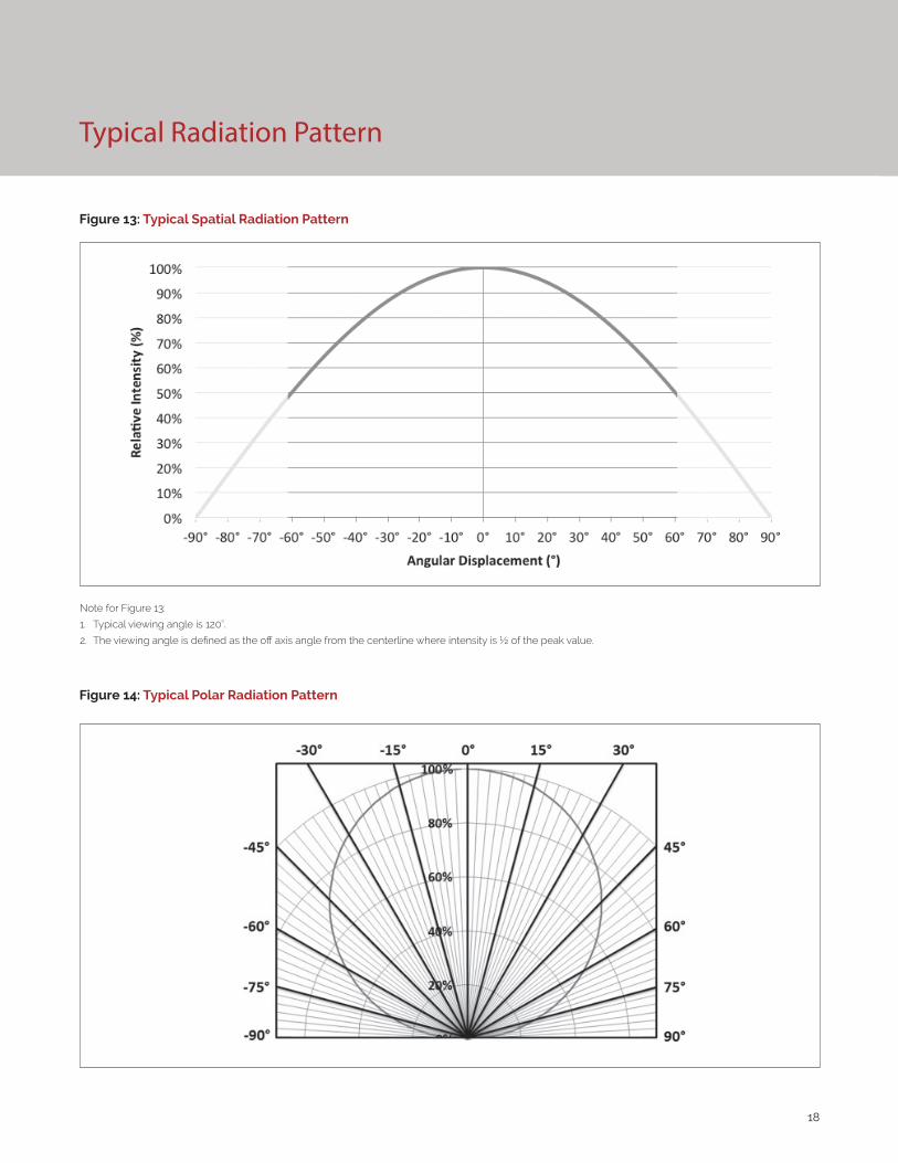
Typical Radiation Pattern
Figure 13: Typical Spatial Radiation Pattern
Figure 14: Typical Polar Radiation Pattern
Note for Figure 13:
1. Typical viewing angle is 120⁰.
2. The viewing angle is defined as the off axis angle from the centerline where intensity is ½ of the peak value.

19
Typical Color Spectrum
Figure 15: Typical Color Spectrum
Note for Figure 15:
1. Color spectra measured at nominal current for Tj = Tc = 25°C.
2. Color spectra shown is 3000K and 80 CRI.
3. Color spectra shown is 4000K and 80 CRI.
4. Color spectra shown is 5000K and 70 CRI.
4. Color spectra shown is 6500K and 70 CRI.
0%
10%
20%
30%
40%
50%
60%
70%
80%
90%
100%
110%
400 450 500 550 600 650 700 750 800
Rela
tive
Spec
tral
Pow
er D
istr
ibut
ion
Wavelength (nm)
3000K4000K5000K6500K
Figure 16: Typical Color Spectrum for Décor Series
Note for Figure 16:
1. Color spectra measured at nominal current for Tj = Tc = 25°C.
0
0.1
0.2
0.3
0.4
0.5
0.6
0.7
0.8
0.9
1
400 450 500 550 600 650 700 750 800
Re
lati
ve S
pe
ctra
l Po
we
r D
istr
ibu
tio
n
Wavelength (nm)
17E
25E
20B
27H
30H
30G (Décor Series Showcase)

20
Mechanical Dimensions
Figure 17: Drawing for V13 LED Array
Notes for Figure 17:
1. Drawings are not to scale.
2. Drawing dimensions are in millimeters.
3. Unless otherwise specified, tolerances are ±0.1mm.
4. Solder pad labeled “+” denotes positive contact.
5. Refer to Application Notes AN101 for product handling, mounting and heat sink recommendations.
6. The optical center of the LED Array is nominally defined by the mechanical center of the array to a tolerance of ± 0.2mm.
7. Bridgelux maintains a flatness of 0.10mm across the mounting surface of the array.

21
Figure 18: Warm and Neutral White Test Bins in xy Color
Space
Figure 19: Cool White Test Bins in xy Color Space
Color Binning Information
Bin Code 1750K 2000K 2500K 2700K 3000K1 3500K1 4000K1
ANSI Bin(for reference only) - - - (2580K - 2870K) (2870K - 3220K) (3220K - 3710K) (3710K - 4260K)
73 (3 SDCM) - - - (2651K - 2794K) (2968K - 3136K) (3369K - 3586K) (3851K - 4130K)
72 (2 SDCM) - - - (2674K - 2769K) (2995K - 3107K) (3404K - 3548K) (3895K - 4081K)
Center Point (x,y) (0.5167, 0.336) (0.5280, 0.4100) (0.4765, 0.4137) (0.4578, 0.4101)(0.4338, 0.403)
(0.4465, 0.4024)2 (0.4073, 0.3917) (0.3818, 0.3797)
Table 8: Warm and Neutral White xy Bin Coordinates and Associated Typical CCT
Bin Code 5000K 5700K 6500K
ANSI Bin (for reference only) (4745K - 5311K) (5312K - 6022K) (6022K - 7042K)
74 (4 SDCM) (4801K - 5282K) (5829K - 5481K) (6270K - 6765K)
73 (3 SDCM) (4835K - 5215K) (4590K - 5820K) (6250K - 6745K)
Center Point (x,y) (0.3447, 0.3553) (0.3287, 0.3417) (0.3123, 0.3282)
Table 9: Cool White xy Bin Coordinates and Associated Typical CCT (product is hot targeted to Tc = 85°C)
Note: Pulsed Test Conditions, Tc = 25°C
Note for Table 8:
1. Color Binning information excludes Décor Series Class A products. Please contact your Bridgelux Sales Representative for more information. 2. Center Point for Decor Series Showcase.
0.34
0.36
0.38
0.4
0.42
0.44
0.36 0.39 0.42 0.45 0.48 0.51 0.54
Y
X
3 SDCM
4 SDCM
3500K
2500K4SDCM
1750K4SDCM
2000K3SDCM
2700K
3000K
4000K
0.3
0.31
0.32
0.33
0.34
0.35
0.36
0.37
0.38
0.39
0.3 0.31 0.32 0.33 0.34 0.35 0.36
Y
X
4 SDCM
3 SDCM
6500K
5700K
5000K

22
Packaging and Labeling
Figure 20: Drawing for V13 Packaging Tray
Notes for Figure 20:
1. Each tube holds 25 V13 COB arrays.
2. One tube is sealed in an anti-static bag. Four bags are placed in a shipping box. Depending on quantities ordered, a bigger shipping box, containing four boxes may be used to ship products.
3. Each bag and box is to be labeled as shown above.
4. Dimensions for each tube are 21.3 (W) x 9.5(H) x 505 (L). Dimensions for the anti-static bag are 75 (W) x 615 (L) x 3.1 (T) mm. Dimensions for the shipping box are 58.7 x 13.3 x 7.9 cm.
23
Packaging and Labeling
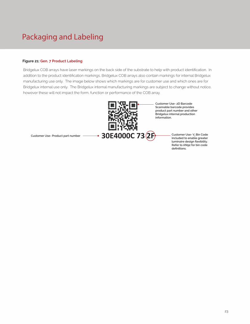
Figure 21: Gen. 7 Product Labeling
Bridgelux COB arrays have laser markings on the back side of the substrate to help with product identification. In
addition to the product identification markings, Bridgelux COB arrays also contain markings for internal Bridgelux
manufacturing use only. The image below shows which markings are for customer use and which ones are for
Bridgelux internal use only. The Bridgelux internal manufacturing markings are subject to change without notice,
however these will not impact the form, function or performance of the COB array.
Customer Use- 2D Barcode Scannable barcode provides product part number and other Bridgelux internal production information.
Customer Use- Product part number 30E4000C 73 2F Customer Use- Vf Bin Code included to enable greater luminaire design flexibility. Refer to AN92 for bin code definitions.

24
Design Resources
Disclaimers
Precautions
Application Notes
Bridgelux has developed a comprehensive set of application notes and design resources to assist customers in successfully designing with the V Series product family of LED array products. For all available application notes visit www.bridgelux.com.
Optical Source Models
Optical source models and ray set files are available for all Bridgelux products. For a list of available formats, visit www.bridgelux.com.
MINOR PRODUCT CHANGE POLICY
The rigorous qualification testing on products offered by Bridgelux provides performance assurance. Slight cosmetic changes that do not affect form, fit, or function may occur as Bridgelux continues product optimization.
CAUTION: CHEMICAL EXPOSURE HAZARD
Exposure to some chemicals commonly used in luminaire manufacturing and assembly can cause damage to the LED array. Please consult Bridgelux Application Note AN101 for additional information.
CAUTION: RISK OF BURN
Do not touch the V Series LED array during operation. Allow the array to cool for a sufficient period of time before handling. The V Series LED array may reach elevated temperatures such that could burn skin when touched.
3D CAD Models
Three dimensional CAD models depicting the product outline of all Bridgelux V Series LED arrays are available in both IGS and STEP formats. Please contact your Bridgelux sales representative for assistance.
LM80
LM80 testing has been completed and the LM80 report is now available. Please contact your Bridgelux sales representative for LM-80 report.
STANDARD TEST CONDITIONS
Unless otherwise stated, array testing is performed at the nominal drive current.
CAUTION
CONTACT WITH LIGHT EMITTING SURFACE (LES)
Avoid any contact with the LES. Do not touch the LES of the LED array or apply stress to the LES (yellow phosphor resin area). Contact may cause damage to the LED array.
Optics and reflectors must not be mounted in contact with the LES (yellow phosphor resin area).

25
About Bridgelux: We Build Light That Transforms
© 2016-2017 Bridgelux, Inc. All rights reserved 2016. Product specifications are subject to change without notice. Bridgelux, the Bridgelux stylized logo design and Vero are registered trademarks, and Decor Series is a trademark of Bridgelux, Inc. All other trademarks are the property of their respective owners.
Bridgelux Gen 7 V13 Array Series Product Data Sheet DS101 Rev. K (12/2017)
46430 Fremont Boulevard
Fremont, CA 94538
Tel (925) 583-8400
www.bridgelux.com
At Bridgelux, we help companies, industries and people experience the power and possibility of light. Since 2002, we’ve designed LED solutions that are high performing, energy efficient, cost effective and easy to integrate. Our focus is on light’s impact on human behavior, deliver-ing products that create better environments, experiences and returns—both experiential and financial. And our patented technology drives new platforms for commercial and industrial luminaires.
For more information about the company, please visit bridgelux.comtwitter.com/Bridgeluxfacebook.com/Bridgeluxyoutube.com/user/Bridgeluxlinkedin.com/company/bridgelux-inc-_2WeChat ID: BridgeluxInChina