Embed Size (px)
Citation preview

Bridgelux® Gen. 7 Décor Series™ Class A LED Array
Product Data Sheet DS95
BXRC-30A1001 | 30A2001 | 30A4001 | 30A10K1
BXRC-35A1001 | 35A2001 | 35A4001 | 35A10K1
BXRC-40A1001 | 40A2001 | 40A4001 | 40A10K1
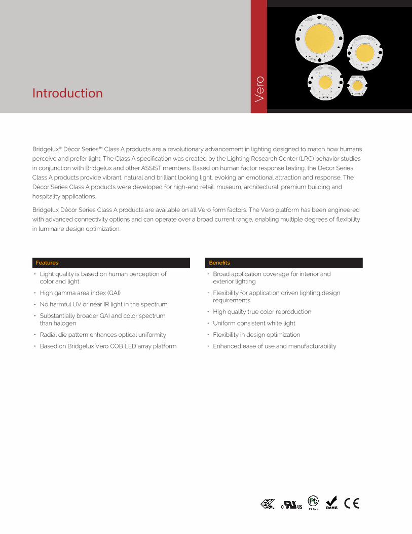
Introduction
Bridgelux® Décor Series™ Class A products are a revolutionary advancement in lighting designed to match how humans
perceive and prefer light. The Class A specification was created by the Lighting Research Center (LRC) behavior studies
in conjunction with Bridgelux and other ASSIST members. Based on human factor response testing, the Décor Series
Class A products provide vibrant, natural and brilliant looking light, evoking an emotional attraction and response. The
Décor Series Class A products were developed for high-end retail, museum, architectural, premium building and
hospitality applications.
Bridgelux Décor Series Class A products are available on all Vero form factors. The Vero platform has been engineered
with advanced connectivity options and can operate over a broad current range, enabling multiple degrees of flexibility
in luminaire design optimization.
Ve
roFeatures
• Light quality is based on human perception of color and light
• High gamma area index (GAI)
• No harmful UV or near IR light in the spectrum
• Substantially broader GAI and color spectrum than halogen
• Radial die pattern enhances optical uniformity
• Based on Bridgelux Vero COB LED array platform
Benefits
• Broad application coverage for interior and exterior lighting
• Flexibility for application driven lighting design requirements
• High quality true color reproduction
• Uniform consistent white light
• Flexibility in design optimization
• Enhanced ease of use and manufacturability

Contents
Product Feature Map 2
Product Nomenclature 2
Product Selection Guide 3
Performance at Commonly Used Drive Currents 6
Electrical Characteristics 11
Absolute Maximum Ratings 12
Performance Curves 13
Typical Radiation Pattern 19
Mechanical Dimensions 20
Packaging and Labeling 24
Design Resources 27
Precautions 27
Disclaimers 27
About Bridgelux 28
1

Product Feature Map
In addition to delivering the performance and light quality required for many lighting applications, Décor Series Class A LED arrays incorporate several features to
Product Nomenclature
The part number designation for Bridgelux Vero LED Class A arrays is explained as follows:
simplify the design integration and manufacturing process, accelerate time to market and reduce system costs.
2
1 2 3 4 5 6 7 8 9 10 11 – 12 – 13 14
Product Family CCT Bin Options3 = 3 SDCM
Nominal Flux1001- 1000lm2001- 2000lm4001- 4000lm10K1- 10,000lm
Typical GAIGAI >80
Array Configuration
Nominal CCT30 = 3,000K35 = 3,500K40 = 4,000K
BXRC – 30 A 1001 – B – 7 3
2D barcode provides full manufacturing traceability
Polarity indication marks simplify manufacturing operator instructions
Optics location/mounting features
Mounting holes
Zhaga Book 3 compatible mounting locations
Solderless connector port enables simplified manufacturing processes, reduced inventory
carrying costs and can enable field upgradability
Thermally isolated solder pads reduce manufacturing cycle time and complexity
Tc Measurement point
Radial die configuration improves lumen density and beam control
Optional Molex Pico-EZmate™ connector harness (sold separately)
Top side part number marking improves inventory management and outgoing quality control
Gen. 7

Product Selection Guide
The following product configurations are available:
Table 1: Selection Guide, Pulsed Measurement Data (Tj = Tc = 25°C)
Notes for Table 1:
1. Nominal CCT is defined by the Lighting Research Center’s Class A definition. The center of the Class A color bin is on the corresponding isothermal line.
2. To help ensure optimal fixture level performance, GAI is measured at the fixture level, on axis, at a case temperature of 70°C. GAI may vary depending on fixture design and performance.
3. CRI Values are specified as typical.
4. Drive current is referred to as nominal drive current.
5. Products tested under pulsed condition (10ms pulse width) at nominal test current where Tj (junction temperature) = Tc (case temperature) = 25°C.
6. Typical performance values are provided as a reference only and are not a guarantee of performance.
7. Bridgelux maintains a ±7% tolerance on flux measurements.
8. Minimum flux values at the nominal test current are guaranteed by 100% test.
Product Part NumberNominal
CCT1 (K)
GAI2 CRI3
Nominal Drive
Current4 (mA)
Typical Pulsed Flux5,6,7
Tc = 25ºC(lm)
Minimum Pulsed Flux7,8
Tc = 25ºC(lm)
Typical Vf (V)
Typical Power
(W)
Typical Efficacy (lm/W)
Décor Class A Vero 10 BXRC-30A1001-B-73 3000 80 93 270 1086 959 35.0 9.4 116
Décor Class A Vero 10 BXRC-30A1001-C-73 3000 80 93 360 1448 1274 35.0 12.5 116
Décor Class A Vero 10 BXRC-30A1001-D-73 3000 80 93 350 1056 982 26.0 9.1 116
Décor Class A Vero 10 BXRC-35A1001-B-73 3500 80 93 270 1170 1033 35.0 9.4 125
Décor Class A Vero 10 BXRC-35A1001-C-73 3500 80 93 360 1560 1373 35.0 12.5 125
Décor Class A Vero 10 BXRC-35A1001-D-73 3500 80 93 350 1138 1058 26.0 9.1 125
Décor Class A Vero 10 BXRC-40A1001-B-73 4000 80 93 270 1245 1099 35.0 9.4 133
Décor Class A Vero 10 BXRC-40A1001-C-73 4000 80 93 360 1660 1461 35.0 12.5 133
Décor Class A Vero 10 BXRC-40A1001-D-73 4000 80 93 350 1210 1126 26.0 9.1 133
Décor Class A Vero 13 BXRC-30A2001-B-73 3000 80 93 450 1873 1765 35.0 15.6 120
Décor Class A Vero 13 BXRC-30A2001-C-73 3000 80 93 630 2622 2412 35.0 21.9 120
Décor Class A Vero 13 BXRC-30A2001-D-73 3000 80 93 500 1907 1773 31.8 15.9 120
Décor Class A Vero 13 BXRC-35A2001-B-73 3500 80 93 450 2014 1898 35.0 15.6 129
Décor Class A Vero 13 BXRC-35A2001-C-73 3500 80 93 630 2819 2593 35.0 21.9 129
Décor Class A Vero 13 BXRC-35A2001-D-73 3500 80 93 500 2050 1906 31.8 15.9 129
Décor Class A Vero 13 BXRC-40A2001-B-73 4000 80 93 450 2154 2030 35.0 15.6 138
Décor Class A Vero 13 BXRC-40A2001-C-73 4000 80 93 630 3015 2774 35.0 21.9 138
Décor Class A Vero 13 BXRC-40A2001-D-73 4000 80 93 500 2194 2039 31.8 15.9 138
Décor Class A Vero 18 BXRC-30A4001-B-73 3000 80 93 900 3745 3515 35.0 31.2 120
Décor Class A Vero 18 BXRC-30A4001-C-73 3000 80 93 1170 4870 4480 35.0 40.6 120
Décor Class A Vero 18 BXRC-30A4001-D-73 3000 80 93 1050 3641 3441 29.0 30.4 120
Décor Class A Vero 18 BXRC-35A4001-B-73 3500 80 93 900 4026 3778 35.0 31.2 129
Décor Class A Vero 18 BXRC-35A4001-C-73 3500 80 93 1170 5235 4816 35.0 40.6 129
Décor Class A Vero 18 BXRC-35A4001-D-73 3500 80 93 1050 3915 3699 29.0 30.4 129
Décor Class A Vero 18 BXRC-40A4001-B-73 4000 80 93 900 4307 4042 35.0 31.2 138
Décor Class A Vero 18 BXRC-40A4001-C-73 4000 80 93 1170 5600 5152 35.0 40.6 138
Décor Class A Vero 18 BXRC-40A4001-D-73 4000 80 93 1050 4188 3957 29.0 30.4 138
Décor Class A Vero 29 BXRC-30A10K1-B-73 3000 80 93 1800 11237 10338 52.0 93.6 120
Décor Class A Vero 29 BXRC-30A10K1-C-73 3000 80 93 1710 14233 13095 69.4 118.6 120
Décor Class A Vero 29 BXRC-30A10K1-D-73 3000 80 93 2100 9468 8710 37.6 78.9 120
Décor Class A Vero 29 BXRC-35A10K1-B-73 3500 80 93 1800 12080 11113 52.0 93.6 129
Décor Class A Vero 29 BXRC-35A10K1-C-73 3500 80 93 1710 15301 14077 69.4 118.6 129
Décor Class A Vero 29 BXRC-35A10K1-D-73 3500 80 93 2100 10178 9363 37.6 78.9 129
Décor Class A Vero 29 BXRC-40A10K1-B-73 4000 80 93 1800 12922 11889 52.0 93.6 138
Décor Class A Vero 29 BXRC-40A10K1-C-73 4000 80 93 1710 16368 15059 69.4 118.6 138
Décor Class A Vero 29 BXRC-40A10K1-D-73 4000 80 93 2100 10888 10016 37.6 78.9 138
3
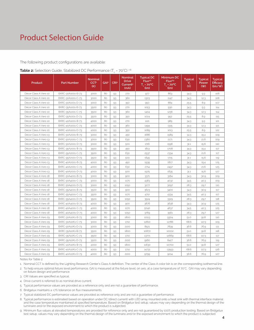
Product Selection Guide
The following product configurations are available:
Table 2: Selection Guide, Stabilized DC Performance (Tc = 70°C) 7,8
Notes for Table 2:
1. Nominal CCT is defined by the Lighting Research Center’s Class A definition. The center of the Class A color bin is on the corresponding isothermal line.
2. To help ensure optimal fixture level performance, GAI is measured at the fixture level, on axis, at a case temperature of 70°C. GAI may vary depending on fixture design and performance.
3. CRI Values are specified as typical.
4. Drive current is referred to as nominal drive current.
5. Typical performance values are provided as a reference only and are not a guarantee of performance.
6. Bridgelux maintains a ±7% tolerance on flux measurements.
7. Typical stabilized DC performance values are provided as reference only and are not a guarantee of performance.
8. Typical performance is estimated based on operation under DC (direct current) with LED array mounted onto a heat sink with thermal interface material and the case temperature maintained at specified temperature. Based on Bridgelux test setup, values may vary depending on the thermal design of the luminaire and/or the exposed environment to which the product is subjected.
9. Minimum flux values at elevated temperatures are provided for reference only and are not guaranteed by 100% production testing. Based on Bridgelux test setup, values may vary depending on the thermal design of the luminaire and/or the exposed environment to which the product is subjected.
4
Product Part NumberNominal
CCT1 (K)
GAI2 CRI3
Nominal Drive
Current4 (mA)
Typical DC Flux5,6
Tc = 70ºC(lm)
Minimum DC Flux6,9
Tc = 70ºC(lm)
Typical Vf (V)
Typical Power
(W)
Typical Efficacy (lm/W)
Décor Class A Vero 10 BXRC-30A1001-B-73 3000 80 93 270 977 863 34.3 9.3 106
Décor Class A Vero 10 BXRC-30A1001-C-73 3000 80 93 360 1303 1147 34.3 12.3 106
Décor Class A Vero 10 BXRC-30A1001-D-73 3000 80 93 350 950 884 25.5 8.9 107
Décor Class A Vero 10 BXRC-35A1001-B-73 3500 80 93 270 1053 930 34.3 9.3 114
Décor Class A Vero 10 BXRC-35A1001-C-73 3500 80 93 360 1404 1236 34.3 12.3 114
Décor Class A Vero 10 BXRC-35A1001-D-73 3500 80 93 350 1024 952 25.5 8.9 115
Décor Class A Vero 10 BXRC-40A1001-B-73 4000 80 93 270 1121 989 34.3 9.3 121
Décor Class A Vero 10 BXRC-40A1001-C-73 4000 80 93 360 1494 1315 34.3 12.3 121
Décor Class A Vero 10 BXRC-40A1001-D-73 4000 80 93 350 1089 1013 25.5 8.9 122
Décor Class A Vero 13 BXRC-30A2001-B-73 3000 80 93 450 1686 1589 34.3 15.4 109
Décor Class A Vero 13 BXRC-30A2001-C-73 3000 80 93 630 2360 2171 34.3 21.6 109
Décor Class A Vero 13 BXRC-30A2001-D-73 3000 80 93 500 1716 1596 31.1 15.6 110
Décor Class A Vero 13 BXRC-35A2001-B-73 3500 80 93 450 1813 1708 34.3 15.4 117
Décor Class A Vero 13 BXRC-35A2001-C-73 3500 80 93 630 2537 2334 34.3 21.6 117
Décor Class A Vero 13 BXRC-35A2001-D-73 3500 80 93 500 1845 1715 31.1 15.6 119
Décor Class A Vero 13 BXRC-40A2001-B-73 4000 80 93 450 1939 1827 34.3 15.4 125
Décor Class A Vero 13 BXRC-40A2001-C-73 4000 80 93 630 2714 2497 34.3 21.6 125
Décor Class A Vero 13 BXRC-40A2001-D-73 4000 80 93 500 1975 1835 31.1 15.6 127
Décor Class A Vero 18 BXRC-30A4001-B-73 3000 80 93 900 3371 3164 34.3 30.9 109
Décor Class A Vero 18 BXRC-30A4001-C-73 3000 80 93 1170 4383 4032 34.5 40.3 109
Décor Class A Vero 18 BXRC-30A4001-D-73 3000 80 93 1050 3277 3097 28.3 29.7 110
Décor Class A Vero 18 BXRC-35A4001-B-73 3500 80 93 900 3623 3400 34.3 30.9 117
Décor Class A Vero 18 BXRC-35A4001-C-73 3500 80 93 1170 4712 4334 34.5 40.3 117
Décor Class A Vero 18 BXRC-35A4001-D-73 3500 80 93 1050 3524 3329 28.3 29.7 118
Décor Class A Vero 18 BXRC-40A4001-B-73 4000 80 93 900 3876 3638 34.3 30.9 125
Décor Class A Vero 18 BXRC-40A4001-C-73 4000 80 93 1170 5040 4637 34.5 40.3 125
Décor Class A Vero 18 BXRC-40A4001-D-73 4000 80 93 1050 3769 3561 28.3 29.7 127
Décor Class A Vero 29 BXRC-30A10K1-B-73 3000 80 93 1800 10113 9304 51.0 91.8 110
Décor Class A Vero 29 BXRC-30A10K1-C-73 3000 80 93 1710 12810 11786 68.6 117.3 109
Décor Class A Vero 29 BXRC-30A10K1-D-73 3000 80 93 2100 8521 7839 36.6 76.9 111
Décor Class A Vero 29 BXRC-35A10K1-B-73 3500 80 93 1800 10872 10002 51.0 91.8 118
Décor Class A Vero 29 BXRC-35A10K1-C-73 3500 80 93 1710 13771 12669 68.6 117.3 117
Décor Class A Vero 29 BXRC-35A10K1-D-73 3500 80 93 2100 9160 8427 36.6 76.9 119
Décor Class A Vero 29 BXRC-40A10K1-B-73 4000 80 93 1800 11630 10700 51.0 91.8 127
Décor Class A Vero 29 BXRC-40A10K1-C-73 4000 80 93 1710 14731 13553 68.6 117.3 126
Décor Class A Vero 29 BXRC-40A10K1-D-73 4000 80 93 2100 9799 9014 36.6 76.9 127

Product Selection Guide
The following product configurations are available:
Table 3: Selection Guide, Stabilized DC Performance (Tc = 85°C) 7,8
Notes for Table 3:
1. Nominal CCT is defined by the Lighting Research Center’s Class A definition. The center of the Class A color bin is on the corresponding isothermal line.
2. To help ensure optimal fixture level performance, GAI is measured at the fixture level, on axis, at a case temperature of 70°C. GAI may vary depending on fixture design and performance.
3. CRI Values are specified as typical.
4. Drive current is referred to as nominal drive current.
5. Typical performance values are provided as a reference only and are not a guarantee of performance.
6. Bridgelux maintains a ±7% tolerance on flux measurements.
7. Typical stabilized DC performance values are provided as reference only and are not a guarantee of performance.
8. Typical performance is estimated based on operation under DC (direct current) with LED array mounted onto a heat sink with thermal interface material and the case temperature maintained at specified temperature. Based on Bridgelux test setup, values may vary depending on the thermal design of the luminaire and/or the exposed environment to which the product is subjected.
9. Minimum flux values at elevated temperatures are provided for reference only and are not guaranteed by 100% production testing. Based on Bridgelux test setup, values may vary depending on the thermal design of the luminaire and/or the exposed environment to which the product is subjected.
Product Part NumberNominal
CCT1 (K)
GAI2 CRI3
Nominal Drive
Current4 (mA)
Typical DC Flux5,6
Tc = 85ºC(lm)
Minimum DC Flux6,9
Tc = 85ºC(lm)
Typical Vf (V)
Typical Power
(W)
Typical Efficacy (lm/W)
Décor Class A Vero 10 BXRC-30A1001-B-73 3000 80 93 270 977 863 34.0 9.2 106
Décor Class A Vero 10 BXRC-30A1001-C-73 3000 80 93 360 1303 1147 34.0 12.3 106
Décor Class A Vero 10 BXRC-30A1001-D-73 3000 80 93 350 950 884 25.3 8.9 107
Décor Class A Vero 10 BXRC-35A1001-B-73 3500 80 93 270 1053 930 34.0 9.2 115
Décor Class A Vero 10 BXRC-35A1001-C-73 3500 80 93 360 1404 1236 34.0 12.3 115
Décor Class A Vero 10 BXRC-35A1001-D-73 3500 80 93 350 1024 952 25.3 8.9 116
Décor Class A Vero 10 BXRC-40A1001-B-73 4000 80 93 270 1121 989 34.0 9.2 122
Décor Class A Vero 10 BXRC-40A1001-C-73 4000 80 93 360 1494 1315 34.0 12.3 122
Décor Class A Vero 10 BXRC-40A1001-D-73 4000 80 93 350 1089 1013 25.3 8.9 123
Décor Class A Vero 13 BXRC-30A2001-B-73 3000 80 93 450 1686 1589 34.1 15.3 110
Décor Class A Vero 13 BXRC-30A2001-C-73 3000 80 93 630 2360 2171 34.1 21.5 110
Décor Class A Vero 13 BXRC-30A2001-D-73 3000 80 93 500 1716 1596 30.9 15.5 111
Décor Class A Vero 13 BXRC-35A2001-B-73 3500 80 93 450 1813 1708 34.1 15.3 118
Décor Class A Vero 13 BXRC-35A2001-C-73 3500 80 93 630 2537 2334 34.1 21.5 118
Décor Class A Vero 13 BXRC-35A2001-D-73 3500 80 93 500 1845 1715 30.9 15.5 119
Décor Class A Vero 13 BXRC-40A2001-B-73 4000 80 93 450 1939 1827 34.1 15.3 126
Décor Class A Vero 13 BXRC-40A2001-C-73 4000 80 93 630 2714 2497 34.1 21.5 126
Décor Class A Vero 13 BXRC-40A2001-D-73 4000 80 93 500 1975 1835 30.9 15.5 128
Décor Class A Vero 18 BXRC-30A4001-B-73 3000 80 93 900 3371 3164 34.1 30.7 110
Décor Class A Vero 18 BXRC-30A4001-C-73 3000 80 93 1170 4383 4032 34.3 40.1 109
Décor Class A Vero 18 BXRC-30A4001-D-73 3000 80 93 1050 3277 3097 28.1 29.5 111
Décor Class A Vero 18 BXRC-35A4001-B-73 3500 80 93 900 3623 3400 34.1 30.7 118
Décor Class A Vero 18 BXRC-35A4001-C-73 3500 80 93 1170 4712 4334 34.3 40.1 118
Décor Class A Vero 18 BXRC-35A4001-D-73 3500 80 93 1050 3524 3329 28.1 29.5 119
Décor Class A Vero 18 BXRC-40A4001-B-73 4000 80 93 900 3876 3638 34.1 30.7 126
Décor Class A Vero 18 BXRC-40A4001-C-73 4000 80 93 1170 5040 4637 34.3 40.1 126
Décor Class A Vero 18 BXRC-40A4001-D-73 4000 80 93 1050 3769 3561 28.1 29.5 128
Décor Class A Vero 29 BXRC-30A10K1-B-73 3000 80 93 1800 10113 9304 50.7 91.2 111
Décor Class A Vero 29 BXRC-30A10K1-C-73 3000 80 93 1710 12810 11786 68.4 116.9 110
Décor Class A Vero 29 BXRC-30A10K1-D-73 3000 80 93 2100 8521 7839 36.3 76.2 112
Décor Class A Vero 29 BXRC-35A10K1-B-73 3500 80 93 1800 10872 10002 50.7 91.2 119
Décor Class A Vero 29 BXRC-35A10K1-C-73 3500 80 93 1710 13771 12669 68.3 116.8 118
Décor Class A Vero 29 BXRC-35A10K1-D-73 3500 80 93 2100 9160 8427 36.3 76.2 120
Décor Class A Vero 29 BXRC-40A10K1-B-73 4000 80 93 1800 11630 10700 50.7 91.2 128
Décor Class A Vero 29 BXRC-40A10K1-C-73 4000 80 93 1710 14731 13553 68.3 116.8 126
Décor Class A Vero 29 BXRC-40A10K1-D-73 4000 80 93 2100 9799 9014 36.3 76.2 129
5

Performance at Commonly Used Drive Currents
Vero LED arrays are tested to the specifications shown using the nominal drive currents in Table 1. Vero may also
be driven at other drive currents dependent on specific application design requirements. The performance at any
drive current can be derived from the current vs. voltage characteristics shown in Figure 1-12 and the flux vs. current
characteristics shown in Figures 13-24. The performance at commonly used drive currents is summarized in Table 4.
6
Table 4: Product Performance at Commonly Used Drive Currents
Product Part Number GAI CRIDrive
Current1
(mA)
Typical Vf Tc = 25ºC
(V)
Typical Power
Tc = 25ºC(W)
Typical Flux2
Tc = 25ºC(lm)
Typical DC Flux3 Tc = 85ºC
(lm)
Typical Efficacy Tc = 25ºC(lm/W)
Décor Class A Vero 10
BXRC-30A1001-B-73 80 93
135 33.3 4.5 579 521 129
180 33.8 6.1 759 683 125
270 35.0 9.5 1086 977 116
405 36.4 14.8 1593 1434 108
540 37.8 20.4 2041 1837 100
Décor Class A Vero 10
BXRC-30A1001-C-73 80 93
180 33.3 6.0 770 693 129
240 33.8 8.1 1009 908 124
360 35.0 12.6 1448 1303 116
540 36.4 19.7 2108 1898 107
720 37.7 27.1 2693 2424 99
Décor Class A Vero 10
BXRC-30A1001-D-73 80 93
175 24.9 4.4 564 507 129
233 25.4 5.9 740 666 125
350 26.0 9.1 1056 950 116
525 27.4 14.4 1554 1399 108
700 28.4 19.9 1991 1792 100
Décor Class A Vero 10
BXRC-35A1001-B-73 80 93
135 33.3 4.5 623 561 139
180 33.8 6.1 817 736 134
270 35.0 9.5 1170 1053 125
405 36.4 14.8 1716 1545 116
540 37.8 20.4 2199 1979 108
Décor Class A Vero 10
BXRC-35A1001-C-73 80 93
180 33.3 6.0 829 746 139
240 33.8 8.1 1087 978 134
360 35.0 12.6 1560 1404 125
540 36.4 19.7 2272 2044 116
720 37.7 27.1 2902 2612 107
Décor Class A Vero 10
BXRC-35A1001-D-73 80 93
175 24.9 4.4 608 547 139
233 25.4 5.9 797 717 135
350 26.0 9.1 1138 1024 125
525 27.4 14.4 1675 1508 117
700 28.4 19.9 2146 1931 108
Notes for Table 4:
1. Alternate drive currents in Table 4 are provided for reference only and are not a guarantee of performance.
2. Bridgelux maintains a ± 7% tolerance on flux measurements.
3. Typical stabilized DC performance values are provided as reference only and are not a guarantee of performance.

7
Performance at Commonly Used Drive Currents
Table 4: Product Performance at Commonly Used Drive Currents (Continued)
Product Part Number GAI CRIDrive
Current1
(mA)
Typical Vf Tc = 25ºC
(V)
Typical Power
Tc = 25ºC(W)
Typical Flux2
Tc = 25ºC(lm)
Typical DC Flux3 Tc = 85ºC
(lm)
Typical Efficacy Tc = 25ºC(lm/W)
Décor Class A Vero 10
BXRC-40A1001-B-73 80 93
135 33.3 4.5 663 581 148
180 33.8 6.1 870 763 143
270 35.0 9.5 1245 1089 133
405 36.4 14.8 1827 1603 124
540 37.8 20.4 2340 2054 115
Décor Class A Vero 10
BXRC-40A1001-C-73 80 93
180 33.3 6.0 883 459 147
240 33.8 8.1 1156 889 142
360 35.0 12.6 1660 1686 133
540 36.4 19.7 2417 2436 123
720 37.7 27.1 3088 3107 114
Décor Class A Vero 10
BXRC-40A1001-D-73 80 93
175 24.9 4.4 646 638 148
233 25.4 5.9 848 1234 143
350 26.0 9.1 1210 2360 133
525 27.4 14.4 1781 3387 124
700 28.4 19.9 2282 4323 115
Décor Class A Vero 13
BXRC-30A2001-B-73 80 93
113 32.3 3.7 510 454 140
225 33.2 7.5 987 881 132
450 35.0 15.8 1873 1716 120
675 36.3 24.5 2707 2425 111
900 37.5 33.7 3453 3101 102
Décor Class A Vero 13
BXRC-30A2001-C-73 80 93
158 32.3 5.1 708 494 139
315 33.2 10.5 1371 956 131
630 35.0 22.1 2622 1813 120
945 36.4 34.4 3763 2619 109
1260 37.8 47.6 4803 3341 101
Décor Class A Vero 13
BXRC-30A2001-D-73 80 93
125 29.6 3.7 505 685 137
250 30.3 7.6 979 1327 129
500 31.8 15.9 1907 2537 120
750 33.2 24.9 2695 3641 108
1000 34.4 34.4 3446 4648 100
Décor Class A Vero 13
BXRC-35A2001-B-73 80 93
113 32.3 3.7 548 488 150
225 33.2 7.5 1062 947 142
450 35.0 15.8 2014 1845 129
675 36.3 24.5 2911 2607 119
900 37.5 33.7 3713 3334 110
Décor Class A Vero 13
BXRC-35A2001-C-73 80 93
158 32.3 5.1 762 670 149
315 33.2 10.5 1474 1298 141
630 35.0 22.1 2819 2481 129
945 36.4 34.4 4046 3561 118
1260 37.8 47.6 5164 4544 109
Décor Class A Vero 13
BXRC-35A2001-D-73 80 93
125 29.6 3.7 543 478 147
250 30.3 7.6 1052 926 139
500 31.8 15.9 2050 1804 129
750 33.2 24.9 2897 2549 116
1000 34.4 34.4 3704 3260 108
Notes for Table 4:
1. Alternate drive currents in Table 4 are provided for reference only and are not a guarantee of performance.
2. Bridgelux maintains a ± 7% tolerance on flux measurements.
3. Typical stabilized DC performance values are provided as reference only and are not a guarantee of performance.

8
Performance at Commonly Used Drive Currents
Table 4: Product Performance at Commonly Used Drive Currents (Continued)
Product Part Number GAI CRIDrive
Current1
(mA)
Typical Vf Tc = 25ºC
(V)
Typical Power
Tc = 25ºC(W)
Typical Flux2
Tc = 25ºC(lm)
Typical DC Flux3 Tc = 85ºC
(lm)
Typical Efficacy Tc = 25ºC(lm/W)
Décor Class A Vero 13
BXRC-40A2001-B-73 80 93
113 32.3 3.7 587 528 161
225 33.2 7.5 1135 1022 152
450 35.0 15.8 2154 1939 138
675 36.3 24.5 3113 2802 127
900 37.5 33.7 3971 3574 118
Décor Class A Vero 13
BXRC-40A2001-C-73 80 93
158 32.3 5.1 815 733 159
315 33.2 10.5 1577 1419 151
630 35.0 22.1 3015 2714 138
945 36.4 34.4 4327 3895 126
1260 37.8 47.6 5523 4971 116
Décor Class A Vero 13
BXRC-40A2001-D-73 80 93
125 29.6 3.7 581 523 157
250 30.3 7.6 1126 1013 148
500 31.8 15.9 2194 1975 138
750 33.2 24.9 3100 2790 125
1000 34.4 34.4 3964 3568 115
Décor Class A Vero 18
BXRC-30A4001-B-73 80 93
450 33.3 15.0 2011 1810 134
600 33.9 20.4 2638 2374 129
900 35.0 31.5 3745 3371 120
1350 36.7 49.5 5570 5013 113
1800 38.0 68.4 7168 6451 105
Décor Class A Vero 18
BXRC-30A4001-C-73 80 93
585 33.4 19.5 2545 2290 130
780 34.0 26.5 3334 3001 126
1170 35.0 41.0 4870 4383 120
1755 36.8 64.5 7006 6305 109
2340 38.1 89.3 8987 8088 101
Décor Class A Vero 18
BXRC-30A4001-D-73 80 93
525 27.7 14.6 1940 1746 133
700 28.2 19.8 2522 2270 128
1050 29.0 30.5 3641 3277 120
1575 30.4 47.9 5201 4681 109
2100 31.5 66.2 6620 5958 100
Décor Class A Vero 18
BXRC-35A4001-B-73 80 93
450 33.3 15.0 2162 1945 144
600 33.9 20.4 2836 2552 139
900 35.0 31.5 4026 3623 129
1350 36.7 49.5 5988 5389 121
1800 38.0 68.4 7705 6935 113
Décor Class A Vero 18
BXRC-35A4001-C-73 80 93
585 33.4 19.5 2735 2462 140
780 34.0 26.5 3584 3226 135
1170 35.0 41.0 5235 4712 129
1755 36.8 64.5 7531 6778 117
2340 38.1 89.3 9660 8694 108
Décor Class A Vero 18
BXRC-35A4001-D-73 80 93
525 27.7 14.6 2086 1877 143
700 28.2 19.8 2712 2441 137
1050 29.0 30.5 3915 3524 129
1575 30.4 47.9 5592 5033 117
2100 31.5 66.2 7119 6407 108
Notes for Table 4:
1. Alternate drive currents in Table 4 are provided for reference only and are not a guarantee of performance.
2. Bridgelux maintains a ± 7% tolerance on flux measurements.
3. Typical stabilized DC performance values are provided as reference only and are not a guarantee of performance.

9
Performance at Commonly Used Drive Currents
Table 4: Product Performance at Commonly Used Drive Currents (Continued)
Product Part Number GAI CRIDrive
Current1
(mA)
Typical Vf Tc = 25ºC
(V)
Typical Power
Tc = 25ºC(W)
Typical Flux2
Tc = 25ºC(lm)
Typical DC Flux3 Tc = 85ºC
(lm)
Typical Efficacy Tc = 25ºC(lm/W)
Décor Class A Vero 18
BXRC-40A4001-B-73 80 93
450 33.3 15.0 2312 2081 154
600 33.9 20.4 3033 2730 149
900 35.0 31.5 4307 3876 138
1350 36.7 49.5 6406 5765 129
1800 38.0 68.4 8243 7419 120
Décor Class A Vero 18
BXRC-40A4001-C-73 80 93
585 33.4 19.5 2926 2633 150
780 34.0 26.5 3834 3451 145
1170 35.0 41.0 5600 5040 138
1755 36.8 64.5 8056 7251 125
2340 38.1 89.3 10334 9300 116
Décor Class A Vero 18
BXRC-40A4001-D-73 80 93
525 27.7 14.6 2231 2008 153
700 28.2 19.8 2901 2611 147
1050 29.0 30.5 4188 3769 138
1575 30.4 47.9 5982 5384 125
2100 31.5 66.2 7615 6854 115
Décor Class A Vero 29
BXRC-30A10K1-B-73 80 93
900 49.6 44.7 5888 5299 132
1200 50.5 60.6 7769 6992 128
1800 52.0 93.6 11237 10113 120
2700 54.1 146.1 16568 14911 113
3600 55.8 201.0 21362 19225 106
Décor Class A Vero 29
BXRC-30A10K1-C-73 80 93
855 66.2 56.6 8085 7277 143
1140 67.3 76.7 10276 9249 134
1710 69.4 118.7 14233 12810 120
2565 72.1 185.0 20191 18172 109
3420 74.4 254.6 25308 22777 99
Décor Class A Vero 29
BXRC-30A10K1-D-73 80 93
1050 35.4 37.2 5208 4687 140
1400 36.2 50.6 6702 6032 132
2100 37.6 79.0 9468 8521 120
3150 39.5 124.4 13479 12131 108
4200 41.2 172.9 16988 15290 98
Décor Class A Vero 29
BXRC-35A10K1-B-73 80 93
900 49.6 44.7 6330 5697 142
1200 50.5 60.6 8352 7517 138
1800 52.0 93.6 12080 10872 129
2700 54.1 146.1 17811 16030 122
3600 55.8 201.0 22964 20668 114
Décor Class A Vero 29
BXRC-35A10K1-C-73 80 93
855 66.2 56.6 8692 7823 154
1140 67.3 76.7 11048 9943 144
1710 69.4 118.7 15301 13771 129
2565 72.1 185.0 21706 19536 117
3420 74.4 254.6 27207 24486 107
Décor Class A Vero 29
BXRC-35A10K1-D-73 80 93
1050 35.4 37.2 5598 5039 150
1400 36.2 50.6 7205 6485 142
2100 37.6 79.0 10178 9160 129
3150 39.5 124.4 14490 13041 117
4200 41.2 172.9 18262 16436 106
Notes for Table 4:
1. Alternate drive currents in Table 4 are provided for reference only and are not a guarantee of performance.
2. Bridgelux maintains a ± 7% tolerance on flux measurements.
3. Typical stabilized DC performance values are provided as reference only and are not a guarantee of performance.

10
Performance at Commonly Used Drive Currents
Table 4: Product Performance at Commonly Used Drive Currents (Continued)
Product Part Number GAI CRIDrive
Current1
(mA)
Typical Vf Tc = 25ºC
(V)
Typical Power
Tc = 25ºC(W)
Typical Flux2
Tc = 25ºC(lm)
Typical DC Flux3 Tc = 85ºC
(lm)
Typical Efficacy Tc = 25ºC(lm/W)
Décor Class A Vero 29
BXRC-40A10K1-B-73 80 93
900 49.6 44.7 6771 6094 152
1200 50.5 60.6 8934 8041 148
1800 52.0 93.6 12922 11630 138
2700 54.1 146.1 19052 17147 130
3600 55.8 201.0 24565 22108 122
Décor Class A Vero 29
BXRC-40A10K1-C-73 80 93
855 66.2 56.6 9298 8368 164
1140 67.3 76.7 11818 10636 154
1710 69.4 118.7 16368 14731 138
2565 72.1 185.0 23220 20898 126
3420 74.4 254.6 29104 26194 114
Décor Class A Vero 29
BXRC-40A10K1-D-73 80 93
1050 35.4 37.2 5989 5390 161
1400 36.2 50.6 7708 6937 152
2100 37.6 79.0 10888 9799 138
3150 39.5 124.4 15501 13951 125
4200 41.2 172.9 19536 17583 113
Notes for Table 4:
1. Alternate drive currents in Table 4 are provided for reference only and are not a guarantee of performance.
2. Bridgelux maintains a ± 7% tolerance on flux measurements.
3. Typical stabilized DC performance values are provided as reference only and are not a guarantee of performance.
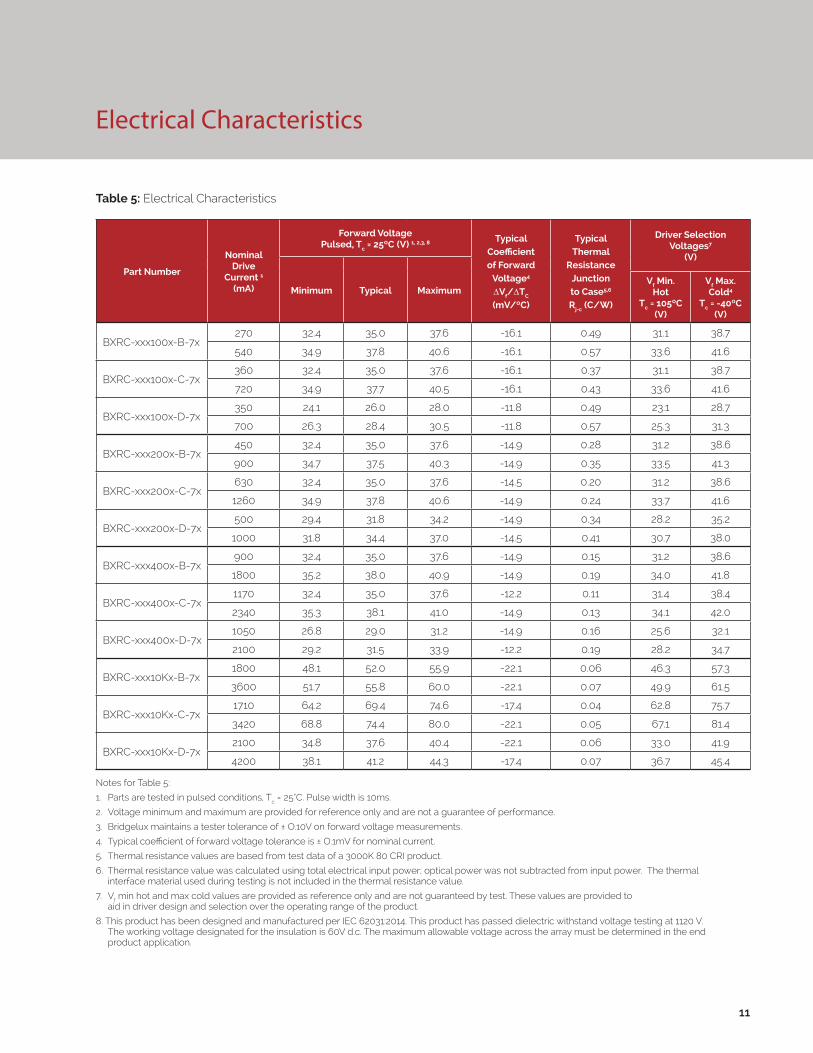
Electrical Characteristics
Notes for Table 5:
1. Parts are tested in pulsed conditions, Tc = 25°C. Pulse width is 10ms.
2. Voltage minimum and maximum are provided for reference only and are not a guarantee of performance.
3. Bridgelux maintains a tester tolerance of ± O.10V on forward voltage measurements.
4. Typical coefficient of forward voltage tolerance is ± O.1mV for nominal current.
5. Thermal resistance values are based from test data of a 3000K 80 CRI product.
6. Thermal resistance value was calculated using total electrical input power; optical power was not subtracted from input power. The thermal interface material used during testing is not included in the thermal resistance value.
7. Vf min hot and max cold values are provided as reference only and are not guaranteed by test. These values are provided to aid in driver design and selection over the operating range of the product.
8. This product has been designed and manufactured per IEC 62031:2014. This product has passed dielectric withstand voltage testing at 1120 V. The working voltage designated for the insulation is 60V d.c. The maximum allowable voltage across the array must be determined in the end product application.
Table 5: Electrical Characteristics
11
Part Number
Nominal Drive
Current 1
(mA)
Forward VoltagePulsed, Tc = 25ºC (V) 1, 2,3, 8 Typical
Coefficient of Forward
Voltage4 ∆Vf/∆TC
(mV/ºC)
Typical Thermal
Resistance Junction to Case5,6 Rj-c (C/W)
Driver Selection Voltages7
(V)
Minimum Typical MaximumVf Min.
Hot Tc = 105ºC
(V)
Vf Max. Cold4
Tc = -40ºC (V)
BXRC-xxx100x-B-7x270 32.4 35.0 37.6 -16.1 0.49 31.1 38.7
540 34.9 37.8 40.6 -16.1 0.57 33.6 41.6
BXRC-xxx100x-C-7x360 32.4 35.0 37.6 -16.1 0.37 31.1 38.7
720 34.9 37.7 40.5 -16.1 0.43 33.6 41.6
BXRC-xxx100x-D-7x350 24.1 26.0 28.0 -11.8 0.49 23.1 28.7
700 26.3 28.4 30.5 -11.8 0.57 25.3 31.3
BXRC-xxx200x-B-7x450 32.4 35.0 37.6 -14.9 0.28 31.2 38.6
900 34.7 37.5 40.3 -14.9 0.35 33.5 41.3
BXRC-xxx200x-C-7x630 32.4 35.0 37.6 -14.5 0.20 31.2 38.6
1260 34.9 37.8 40.6 -14.9 0.24 33.7 41.6
BXRC-xxx200x-D-7x500 29.4 31.8 34.2 -14.9 0.34 28.2 35.2
1000 31.8 34.4 37.0 -14.5 0.41 30.7 38.0
BXRC-xxx400x-B-7x900 32.4 35.0 37.6 -14.9 0.15 31.2 38.6
1800 35.2 38.0 40.9 -14.9 0.19 34.0 41.8
BXRC-xxx400x-C-7x1170 32.4 35.0 37.6 -12.2 0.11 31.4 38.4
2340 35.3 38.1 41.0 -14.9 0.13 34.1 42.0
BXRC-xxx400x-D-7x1050 26.8 29.0 31.2 -14.9 0.16 25.6 32.1
2100 29.2 31.5 33.9 -12.2 0.19 28.2 34.7
BXRC-xxx10Kx-B-7x1800 48.1 52.0 55.9 -22.1 0.06 46.3 57.3
3600 51.7 55.8 60.0 -22.1 0.07 49.9 61.5
BXRC-xxx10Kx-C-7x1710 64.2 69.4 74.6 -17.4 0.04 62.8 75.7
3420 68.8 74.4 80.0 -22.1 0.05 67.1 81.4
BXRC-xxx10Kx-D-7x2100 34.8 37.6 40.4 -22.1 0.06 33.0 41.9
4200 38.1 41.2 44.3 -17.4 0.07 36.7 45.4

12
Absolute Maximum Ratings
Parameter Maximum Rating
LED Junction Temperature 125°C
Storage Temperature -40°C to +105°C
Operating Case Temperature1 105°C
Soldering Temperature2 350°C or lower for a maximum of 10 seconds
BXRC-xxx100x-B-7x BXRC-xxx100x-C-7x BXRC-xxx100x-D-7x
Maximum Drive Current3 540mA 720mA 700mA
Maximum Peak Pulsed Drive Current4 771mA 1029mA 1000mA
Maximum Reverse Voltage5 -60V -60V -45V
BXRC-xxx200x-B-7x BXRC-xxx200x-C-7x BXRC-xxx200x-D-7x
Maximum Drive Current3 900mA 1260mA 1000mA
Maximum Peak Pulsed Drive Current4 1286mA 1800mA 1429mA
Maximum Reverse Voltage5 -60V -60V -55V
BXRC-xxx400x-B-7x BXRC-xxx400x-C-7x BXRC-xxx400x-D-7x
Maximum Drive Current3 1800mA 2340mA 2100mA
Maximum Peak Pulsed Drive Current4 2571mA 3343mA 3000mA
Maximum Reverse Voltage5 -60V -60V -50V
BXRC-xxx10Kx-B-7x BXRC-xxx10Kx-C-7x BXRC-xxx10Kx-D-7x
Maximum Drive Current3 3600mA 3420mA 4200mA
Maximum Peak Pulsed Drive Current4 5143mA 4886mA 6000mA
Maximum Reverse Voltage5 -90V -120V -65V
Table 6: Maximum Ratings
Notes for Table 6:
1. For IEC 62717 requirement, please contact Bridgelux Sales Support.
2. Refer to Bridgelux Application Note AN31, Handling and Assembly of Bridgelux Vero LED arrays, for more information.
3. Arrays may be driven at higher currents however lumen maintenance may be reduced.
4. Bridgelux recommends a maximum duty cycle of 10% and pulse width of 20ms when operating LED Arrays at the maximum peak pulsed current specified. Maximum peak pulsed current indicate values where the LED array can be driven without catastrophic failures.
5. Light emitting diodes are not designed to be driven in reverse voltage and will not produce light under this condition. Maximum rating provided for reference only.

Performance Curves
13
Figure 1: Vero 10B Drive Current vs. Forward Voltage (Tj=Tc=25°C)
Figure 3: Vero 10D Drive Current vs. Forward Voltage (Tj=Tc=25°C)
Figure 2: Vero 10C Drive Current vs. Forward Voltage (Tj=Tc=25°C)
Figure 4: Vero 13B Drive Current vs. Forward Voltage (Tj=Tc=25°C)
0
100
200
300
400
500
600
32 33 34 35 36 37 38
Forw
ard
Cur
rent
(mA)
Forward Voltage (V)
0
100
200
300
400
500
600
700
800
32 33 34 35 36 37 38
Forw
ard
Cur
rent
(mA)
Forward Voltage (V)
Figure 5: Vero 13C Drive Current vs. Forward Voltage (Tj=Tc=25°C)
Figure 6: Vero 13D Drive Current vs. Forward Voltage (Tj=Tc=25°C)
0
100
200
300
400
500
600
700
800
24 25 26 27 28 29
Forw
ard
Cur
rent
(mA)
Forward Voltage (V)
0
100
200
300
400
500
600
700
800
900
1000
32 33 34 35 36 37 38
Forw
ard
Cur
rent
(mA)
Forward Voltage (V)
0
200
400
600
800
1000
1200
1400
32 33 34 35 36 37 38
Forw
ard
Cur
rent
(mA)
Forward Voltage (V)
0
100
200
300
400
500
600
700
800
900
1000
1100
29 30 31 32 33 34 35
Forw
ard
Cur
rent
(mA)
Forward Voltage (V)

0
250
500
750
1000
1250
1500
1750
2000
2250
26 27 28 29 30 31 32
Forw
ard
Cur
rent
(mA)
Forward Voltage (V)
0
500
1000
1500
2000
2500
3000
3500
4000
47 48 49 50 51 52 53 54 55 56 57 58
Forw
ard
Cur
rent
(mA)
Forward Voltage (V)
0
300
600
900
1200
1500
1800
2100
2400
2700
32 33 34 35 36 37 38 39Fo
rwar
d C
urre
nt (m
A)Forward Voltage (V)
0
200
400
600
800
1000
1200
1400
1600
1800
2000
32 33 34 35 36 37 38 39
Forw
ard
Cur
rent
(mA)
Forward Voltage (V)
14
Performance Curves
Figure 7: Vero 18B Drive Current vs. Forward Voltage (Tj=Tc=25°C)
Figure 9: Vero 18D Drive Current vs. Forward Voltage (Tj=Tc=25°C)
Figure 8: Vero 18C Drive Current vs. Forward Voltage (Tj=Tc=25°C)
Figure 10: Vero 29B Drive Current vs. Forward Voltage (Tj=Tc=25°C)
Figure 11: Vero 29C Drive Current vs. Forward Voltage (Tj=Tc=25°C)
Figure 12: Vero 29D Drive Current vs. Forward Voltage (Tj=Tc=25°C)
0
500
1000
1500
2000
2500
3000
3500
4000
63 64 65 66 67 68 69 70 71 72 73 74 75 76
Forw
ard
Cur
rent
(mA)
Forward Voltage (V)
0
500
1000
1500
2000
2500
3000
3500
4000
4500
33 34 35 36 37 38 39 40 41 42
Forw
ard
Cur
rent
(mA)
Forward Voltage (V)

0%
20%
40%
60%
80%
100%
120%
140%
160%
180%
200%
0 100 200 300 400 500 600 700 800 900 1000 1100
Rela
tive
Lum
inou
s Flu
x
Forward Current (mA)
0%
20%
40%
60%
80%
100%
120%
140%
160%
180%
200%
100 250 400 550 700 850 1000 1150 1300
Rela
tive
Lum
inou
s Flu
x
Forward Current (mA)
0%
20%
40%
60%
80%
100%
120%
140%
160%
180%
200%
0 100 200 300 400 500 600 700 800 900 1000
Rela
tive
Lum
inou
s Flu
x
Forward Current (mA)
0%
20%
40%
60%
80%
100%
120%
140%
160%
180%
200%
0 100 200 300 400 500 600 700 800
Rela
tive
Lum
inou
s Flu
xForward Current (mA)
0%
20%
40%
60%
80%
100%
120%
140%
160%
180%
200%
0 100 200 300 400 500 600
Rela
tive
Lum
inou
s Flu
x
Forward Current (mA)
Performance Curves
15
Figure 13: Vero 10B Typical Relative Luminous Flux vs. Drive Current
Figure 15: Vero 10D Typical Relative Luminous Flux vs. Drive Current
Figure 14: Vero 10C Typical Relative Luminous Flux vs. Drive Current
Figure 16: Vero 13B Typical Relative Luminous Flux vs. Drive Current
Figure 17: Vero 13C Typical Relative Luminous Flux vs. Drive Current
Figure 18: Vero 13D Typical Relative Luminous Flux vs. Drive Current
0%
20%
40%
60%
80%
100%
120%
140%
160%
180%
200%
0 100 200 300 400 500 600 700 800
Rela
tive
Lum
inou
s Flu
x
Forward Current (mA)

0%
20%
40%
60%
80%
100%
120%
140%
160%
180%
200%
0 400 800 1200 1600 2000 2400 2800 3200 3600 4000
Rela
tive
Lum
inou
s Flu
x
Forward Current (mA)
0%
20%
40%
60%
80%
100%
120%
140%
160%
180%
200%
0 500 1000 1500 2000 2500 3000 3500 4000
Rela
tive
Lum
inou
s Flu
x
Forward Current (mA)
0%
20%
40%
60%
80%
100%
120%
140%
160%
180%
200%
0 200 400 600 800 1000 1200 1400 1600 1800 2000
Rela
tive
Lum
inou
s Flu
x
Forward Current (mA)
16
Performance Curves
Figure 19: Vero 18B Typical Relative Luminous Flux vs. Drive Current
Figure 21: Vero 18D Typical Relative Luminous Flux vs. Drive Current
Figure 20: Vero 18C Typical Relative Luminous Flux vs. Drive Current
Figure 22: Vero 29B Typical Relative Luminous Flux vs. Drive Current
Figure 23: Vero 29C Typical Relative Luminous Flux vs. Drive Current
Figure 24: Vero 29C Typical Relative Luminous Flux vs. Drive Current
0%
20%
40%
60%
80%
100%
120%
140%
160%
180%
200%
100 400 700 1000 1300 1600 1900 2200 2500Re
lativ
e Lu
min
ous F
lux
Forward Current (mA)
0%
20%
40%
60%
80%
100%
120%
140%
160%
180%
200%
0 500 1000 1500 2000 2500 3000 3500 4000 4500
Rela
tive
Lum
inou
s Flu
x
Forward Current (mA)
y = -7E-08x2 + 0.001x + 0.027
0%
20%
40%
60%
80%
100%
120%
140%
160%
180%
200%
200 400 600 800 1000 1200 1400 1600 1800 2000 2200 2400
Rela
tive
Lum
inou
s Flu
x
Forward Current (mA)

Performance Curves
17
Figure 25: Vero 10 Typical DC Flux vs. Case Temperature1
Figure 27: Vero 18 Typical DC Flux vs. Case Temperature1
Figure 26: Vero 13 Typical DC Flux vs. Case Temperature1
Figure 28: Vero 29 Typical DC Flux vs. Case Temperature1
Note for Figures 25-28:
1. Flux measurements taken under DC conditions.
2. Characteristics shown for warm white based on 3000K and 80 CRI.
3. Characteristics shown for neutral white based on 4000K and 80 CRI.
4. Characteristics shown for cool white based on 5000K and 70 CRI.
5. For other color SKUs, the shift in color will vary. Please contact your Bridgelux Sales Representative for more information.
82%
85%
88%
91%
94%
97%
100%
103%
0 25 50 75 100 125
Rela
tive
Lum
inou
s Flu
x
Case Temperature (°C)
Warm WhiteNeutral WhiteCool White25°C Pulsed
82%
85%
88%
91%
94%
97%
100%
103%
0 25 50 75 100 125
Rela
tive
Lum
inou
s Flu
x
Case Temperature (°C)
Warm WhiteNeutral WhiteCool White25°C Pulsed
82%
85%
88%
91%
94%
97%
100%
103%
0 25 50 75 100 125
Rela
tive
Lum
inou
s Flu
x
Case Temperature (°C)
Warm WhiteNeutral WhiteCool White25°C Pulsed
82%
85%
88%
91%
94%
97%
100%
103%
0 25 50 75 100 125
Rela
tive
Lum
inou
s Flu
x
Case Temperature (°C)
Warm WhiteNeutral WhiteCool White25°C Pulsed

18
Performance Curves
Figure 29: 3000K Class A Color Shift vs. Case Temperature1
Figure 31: 4000K Class A Color Shift vs. Case Temperature1
Figure 30: 3500K Class A Color Shift vs. Case Temperature1
Note for Figures 29-31:
1. Measurements made under DC test conditions at the nominal drive current.
2. Typical color shift is shown with a tolerance of ±0.002.
0.36
0.361
0.362
0.363
0.364
0.365
0.366
0.367
0.368
0.369
0.416 0.4165 0.417 0.4175 0.418 0.4185
ccy
ccx
PulsedCenter Point Color, Tc=25°C25°C
45°C
85°C
105°C
70°C
15°C
0.358
0.36
0.362
0.364
0.366
0.368
0.37
0.392 0.393 0.394 0.395 0.396 0.397
ccy
ccx
PulsedCenter Point Color, Tc=25°C
15°C
45°C
85°C
105°C
70°C
25°C
0.3620
0.3640
0.3660
0.3680
0.3700
0.3720
0.3740
0.3760
0.373 0.374 0.375 0.376 0.377 0.378 0.379
ccy
ccx
PulsedCenter Point Color, Tc=25°C
15°C
45°C
85°C
105°C
70°C
25°C

19
Typical Radiation Pattern
Figure 32: Typical Spatial Radiation Pattern
Figure 33: Typical Polar Radiation Pattern
Notes for Figure 32:
1. Typical viewing angle is 120⁰.
2. The viewing angle is defined as the off axis angle from the centerline where Iv is ½ of the peak value.

20
Mechanical Dimensions
Figure 34: Drawing for Vero 10 LED Array
Notes for Figure 34:
1. Drawings are not to scale.
2. Drawing dimensions are in millimeters.
3. Unless otherwise specified, tolerances are ±0.01mm.
4. Mounting slots (2X) are for M2.5 screws.
5. Bridgelux recommends two tapped holes for mounting screws with 19.0 ± 0.10mm center-to-center spacing.
6. Screws with flat shoulders (pan, dome, button, round, truss, mushroom) provide optimal torque control. Do NOT use flat, countersink, or raised head screws.
7. Solder pads and connector port are labeled “+” and “-“ to denote positive and negative, respectively.
8. It is not necessary to provide electrical connections to both the solder pads and the connector port. Either set may be used depending on application specific design requirements.
9. Refer to Application Notes AN30 and AN31 for product handling, mounting and heat sink recommendations.
10. The optical center of the LED Array is nominally defined by the mechanical center of the array to a tolerance of ± 0.2mm.
11. Bridgelux maintains a flatness of 0.10mm across the mounting surface of the array.

21
Mechanical Dimensions
Figure 35: Drawing for Vero 13 LED Array
Notes for Figure 35:
1. Drawings are not to scale.
2. Drawing dimensions are in millimeters.
3. Unless otherwise specified, tolerances are ±0.01mm.
4. Mounting holes (2X) are for M2.5 screws.
5. Bridgelux recommends two tapped holes for mounting screws with 31.4 ± 0.10mm center-to-center spacing.
6. Screws with flat shoulders (pan, dome, button, round, truss, mushroom) provide optimal torque control. Do NOT use flat, countersink, or raised head screws.
7. Solder pads and connector port are labeled “+” and “-“ to denote positive and negative, respectively.
8. It is not necessary to provide electrical connections to both the solder pads and the connector port. Either set may be used depending on application specific design requirements.
9. Refer to Application Notes AN30 and AN31 for product handling, mounting and heat sink recommendations.
10. The optical center of the LED Array is nominally defined by the mechanical center of the array to a tolerance of ± 0.2mm.
11. Bridgelux maintains a flatness of 0.10mm across the mounting surface of the array.

22
Mechanical Dimensions
Figure 36: Drawing for Vero 18 LED Array
Notes for Figure 36:
1. Drawings are not to scale.
2. Drawing dimensions are in millimeters.
3. Unless otherwise specified, tolerances are ±0.01mm.
4. Mounting holes (2X) are for M2.5 screws.
5. Bridgelux recommends two tapped holes for mounting screws with 31.4 ± 0.10mm center-to-center spacing.
6. Screws with flat shoulders (pan, dome, button, round, truss, mushroom) provide optimal torque control. Do NOT use flat, countersink, or raised head screws.
7. Solder pads and connector port are labeled “+” and “-“ to denote positive and negative, respectively.
8. It is not necessary to provide electrical connections to both the solder pads and the connector port. Either set may be used depending on application specific design requirements.
9. Refer to Application Notes AN30 and AN31 for product handling, mounting and heat sink recommendations.
10. The optical center of the LED Array is nominally defined by the mechanical center of the array to a tolerance of ± 0.2mm.
11. Bridgelux maintains a flatness of 0.10mm across the mounting surface of the array.

23
Mechanical Dimensions
Figure 37: Drawing for Vero 29 LED Array
Notes for Figure 37:
1. Drawings are not to scale.
2. Drawing dimensions are in millimeters.
3. Unless otherwise specified, tolerances are ±0.01mm.
4. Mounting holes (2X) are for M3 screws.
5. Bridgelux recommends two tapped holes for mounting screws with 43.0 ± 0.10mm center-to-center spacing.
6. Screws with flat shoulders (pan, dome, button, round, truss, mushroom) provide optimal torque control. Do NOT use flat, countersink, or raised head screws.
7. Solder pads and connector port are labeled “+” and “-“ to denote positive and negative, respectively.
8. It is not necessary to provide electrical connections to both the solder pads and the connector port. Either set may be used depending on application specific design requirements.
9. Refer to Application Notes AN30 and AN31 for product handling, mounting and heat sink recommendations.
10. The optical center of the LED Array is nominally defined by the mechanical center of the array to a tolerance of ± 0.2mm.
11. Bridgelux maintains a flatness of 0.10mm across the mounting surface of the array.

Packaging and Labeling
24
Figure 38: Drawing for Vero 10 Packaging Tray
Figure 39: Drawing for Vero 13 Packaging Tray
Notes for Figure 38:
1. Dimensions are in millimeters.
2. Drawing is not to scale.
Notes for Figure 39:
1. Dimensions are in millimeters.
2. Drawing is not to scale.

Packaging Labeling
25
Figure 40: Drawing for Vero 18 Packaging Tray
Figure 41: Drawing for Vero 29 Packaging Tray
Notes for Figure 40:
1. Dimensions are in millimeters.
2. Drawing is not to scale.
Notes for Figure 41:
1. Dimensions are in millimeters.
2. Drawing is not to scale.

30E1000C 73
Packaging and Labeling
26
Figure 42: Vero Series Packaging and Labeling
Notes for Figure 42:
1. Each tray holds for Vero 10: 200 COBs, Vero 13: 100 COBs, Vero 18: 100 COBs, Vero 29: 50 COBs.
2. Each tray is vacuum sealed in an anti-static bag and placed in its own box.
3. Each tray, bag and box is to be labeled as shown above.
Figure 43: Product Labeling
Bridgelux COB arrays have laser markings on the back side of the substrate to help with product identification. In
addition to the product identification markings, Bridgelux COB arrays also contain markings for internal Bridgelux
manufacturing use only. The image below shows which markings are for customer use and which ones are for
Bridgelux internal use only. The Bridgelux internal manufacturing markings are subject to change without notice,
however these will not impact the form, function or performance of the COB array.
Customer Use- 2D Barcode Scannable barcode provides product part number and other Bridgelux internal production information.
Internal Bridgelux use only.Customer Use- Product part number

Design Resources
Disclaimers
Precautions
Application Notes
Bridgelux has developed a comprehensive set of application notes and design resources to assist customers in successfully designing with the Vero product family of LED array products. For all available application notes visit www.bridgelux.com.
Optical Source Models
Optical source models and ray set files are available for all Bridgelux products. For a list of available formats, visit www.bridgelux.com.
MINOR PRODUCT CHANGE POLICY
The rigorous qualification testing on products offered by Bridgelux provides performance assurance. Slight cosmetic changes that do not affect form, fit, or function may occur as Bridgelux continues product optimization.
CAUTION: CHEMICAL EXPOSURE HAZARD
Exposure to some chemicals commonly used in luminaire manufacturing and assembly can cause damage to the LED array. Please consult Bridgelux Application Note AN31 for additional information.
CAUTION: EYE SAFETY
Eye safety classification for the use of Bridgelux Vero Series LED arrays is in accordance with specification IEC/TR 62778: Application of IEC 62471 for the assessment of blue light hazard to light sources and luminaires. Vero Series LED arrays are classified as Risk Group 2 (Moderate Risk) when operated at or below 2.5 times the nominal drive current. The Ethr value is 889.79 lux per IEC/TR 62778. Please use appropriate precautions. Under many operating conditions the Vero Series LED arrays are classified as Risk Group 1, for more information please contact your Bridgelux sales representative. It is important that employees working with LEDs are trained to use them safely.
3D CAD Models
Three dimensional CAD models depicting the product outline of all Bridgelux Vero LED arrays are available in both IGS and STEP formats. Please contact your Bridgelux sales representative for assistance.
LM80
LM80 testing is on going. Please contact your Bridgelux sales representative for more information.
CAUTION: RISK OF BURN
Do not touch the Vero LED array during operation. Allow the array to cool for a sufficient period of time before handling. The Vero LED array may reach elevated tem-peratures such that could burn skin when touched.
27
CAUTION
CONTACT WITH LIGHT EMITTING SURFACE (LES)
Avoid any contact with the LES. Do not touch the LES of the LED array or apply stress to the LES (yellow phosphor resin area). Contact may cause damage to the LED array.
Optics and reflectors must not be mounted in contact with the LES (yellow phosphor resin area). Optical devices may be mounted on the top surface of the plastic housing of the Vero LED array. Use the mechanical features of the LED array housing, edges and/or mounting holes to locate and secure optical devices as needed.
STANDARD TEST CONDITIONS
Unless otherwise stated, array testing is performed at the nominal drive current.

28
About Bridgelux: We Build Light That Transforms
© 2016 Bridgelux, Inc. All rights reserved 2016. Product specifications are subject to change without notice. Bridgelux, the Bridgelux stylized logo design and Vero are registered trademarks, and Decor Series is a trademark of Bridgelux, Inc. All other trademarks are the property of their respective owners.
Bridgelux Gen. 7 Vero Decor Series Class A Product Data Sheet DS95 Rev A (07/2016)
101 Portola Avenue
Livermore, CA 94551
Tel (925) 583-8400
Fax (925) 583-8401
www.bridgelux.com
At Bridgelux, we help companies, industries and people experience the power and possibility of light. Since 2002, we’ve designed LED solutions that are high performing, energy efficient, cost effective and easy to integrate. Our focus is on light’s impact on human behavior, deliver-ing products that create better environments, experiences and returns—both experiential and financial. And our patented technology drives new platforms for commercial and industrial luminaires.
For more information about the company, please visit bridgelux.comtwitter.com/Bridgeluxfacebook.com/Bridgeluxlinkedin.com/company/Bridgelux-inc-_2WeChat ID: BridgeluxInChina