Embed Size (px)
Citation preview
Data sheet DS/AQUAP2–EN Rev. J
AquaProbe 2Insertion-type electromagnetic probe flowmeter
Maximum performance, minimum hassle
Now available for use with CheckMaster, Explorer and MagMaster— an innovative, portable validation resource
Excellent accuracy over wide operating flow range in both forward and reverse flow directions— enables accurate measurement of peak daytime flows and
minimal night flows
Battery Operation— 5-year life— no external power supply required— facilitates installation in remote location
AC powered with optional battery backup— continuous measurement even during power-down
Optional built-in multi-speed, multi-channel, dual-variable logger— high precision, high resolution datalogging
'Hot tap' capability— enables installation with no interruption to normal water
supply
'Fit and Flow™'— simplifies installation
3-Year warranty— all AquaProbe sensors come with a factory-standard 3-year
material defect warranty
AquaProbe 2Insertion-type electromagnetic probe flowmeter
2 DS/AQUAP2–EN Rev. J
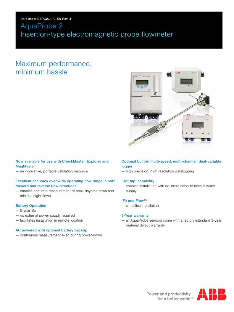
AquaProbe 2AquaProbe 2 extends the capability of the ABB AquaProbe flowmeter by bringing together the proven AquaProbe probe withthe innovative AquaMaster Electronic Display Unit.
AquaProbe has been designed, in close consultation with thewater industry, as an economic and accurate alternative to fullbore metering. It comprises an electromagnetic sensing headmounted on the end of a support rod. This assembly can beinstalled in existing pipelines without the need for the majorexcavations or alterations to pipework associated with full boremeters. It can be fitted without interrupting the water supply andcan be removed easily for periodic calibration or inspection.
Key features include the wide flow range with the minimummeasured velocity well below that detected by insertion turbineor DP devices, no moving parts resulting in increased reliabilityand reduced maintenance.
AquaProbe is ideal for permanent installation to monitor potableor clean water flow. Also through the provision of multipletappings on the supply pipelines, AquaProbe can be used as aportable survey tool to assist in the building of an accuratenetwork model, locate leaks and check the operation of installedfull bore meters.
The high sensitivity of AquaProbe enables it to traverse the pipeto establish the flow profile and so identify hydraulic problems incomplex systems or ensure maximum accuracy from anAquaProbe, which has been installed in a non-ideal location.
No External Power Required for Remote LocationsNo external power supply (two internal batteries) or Explorer separate battery pack
3-year battery life, 5-year battery life with Explorer
Site-replaceable batteries, separate battery pack
Unique battery management system gives a battery replacement window in excess of 1 year, with no flat battery interruption to measurement
AquaProbe 2 is the ideal solution for locations where there is noexternal power. Two user-replaceable internal batteries provide a21/2-year battery life, thus eliminating the high cost of providing amains supply to the meter. AquaProbe 2's extended battery lifeis achieved through new technology design.
AC-powered units have optional battery backup to ensure noloss of flow measurement during power-down periods.
Based on ABB proven technology, AquaProbe 2 is supportedby the expertise of ABB, the world’s leading flow metermanufacturer with many pioneering advances in water flowmetering over the last decade. For example, AquaMag™,MagMaster™, AquaProbe™, CalMaster™ etc. ABB operatenationally, and internationally, accredited flow calibration facilitiesin the UK, Germany, USA, Australia and India. We also offercomprehensive, locally based before- and after-sales service.
AquaProbe 2Insertion-type electromagnetic probe flowmeter
DS/AQUAP2–EN Rev. J 3
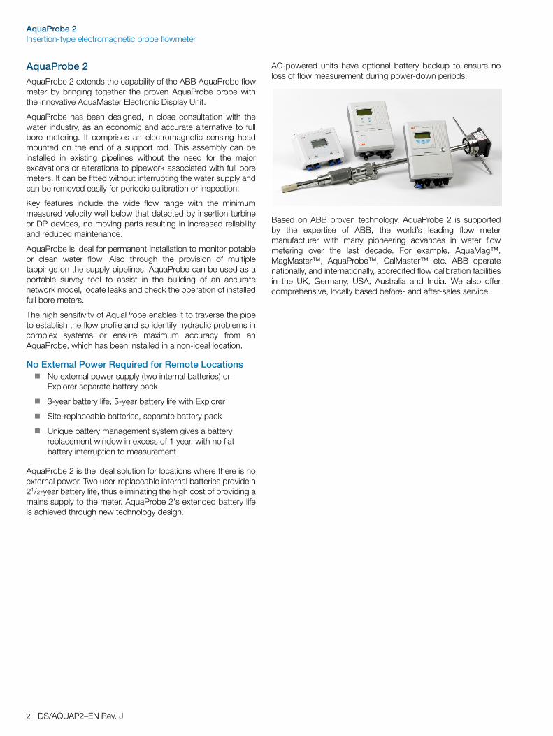
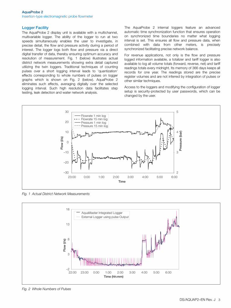
Logger FacilityThe AquaProbe 2 display unit is available with a multichannel,multivariable logger. The ability of the logger to run at twospeeds simultaneously enables the user to investigate, inprecise detail, the flow and pressure activity during a period ofinterest. The logger logs both flow and pressure via a directdigital transfer of data, thereby ensuring optimum accuracy andresolution of measurement. Fig. 1 (below) illustrates actualdistrict network measurements showing extra detail capturedutilizing the twin loggers. Traditional techniques of countingpulses over a short logging interval leads to ‘quantization’effects corresponding to whole numbers of pulses on loggergraphs which is shown on Fig. 2 (below). AquaProbe 2eliminates such effects, averaging digitally over the selectedlogging interval. Such high resolution data facilitates steptesting, leak detection and water network analysis.
The AquaProbe 2 internal loggers feature an advancedautomatic time synchronization function that ensures operationon synchronized time boundaries no matter what logginginterval is set. This ensures all flow and pressure data, whencombined with data from other meters, is preciselysynchronized facilitating precise network balance.
For revenue applications, not only is the flow and pressurelogged information available, a totalizer and tariff logger is alsoavailable to log all volume totals (forward, reverse, net) and tariffreadings totals every midnight. Its memory of 366 days keeps allrecords for one year. The readings stored are the preciseregister volumes and are not inferred by integration of pulses orother similar techniques.
Access to the loggers and modifying the configuration of loggersetup is security-protected by user passwords, which can bechanged by the user.
Fig. 1 Actual District Network Measurements
Fig. 2 Whole Numbers of Pulses
���
���
���
�
��
��
��
����� ���� ���� ���� ���� ���� ���� �������
�
�
�
��� ���������������� ����������������������������������������������������
����
���
�����������
��
�
�
��
��
����� ����� ���� ���� ���� ���� ���� ���� ������������
���������������������� �����!"������� ������������#�����$��#��
����
���
AquaProbe 2Insertion-type electromagnetic probe flowmeter
4 DS/AQUAP2–EN Rev. J
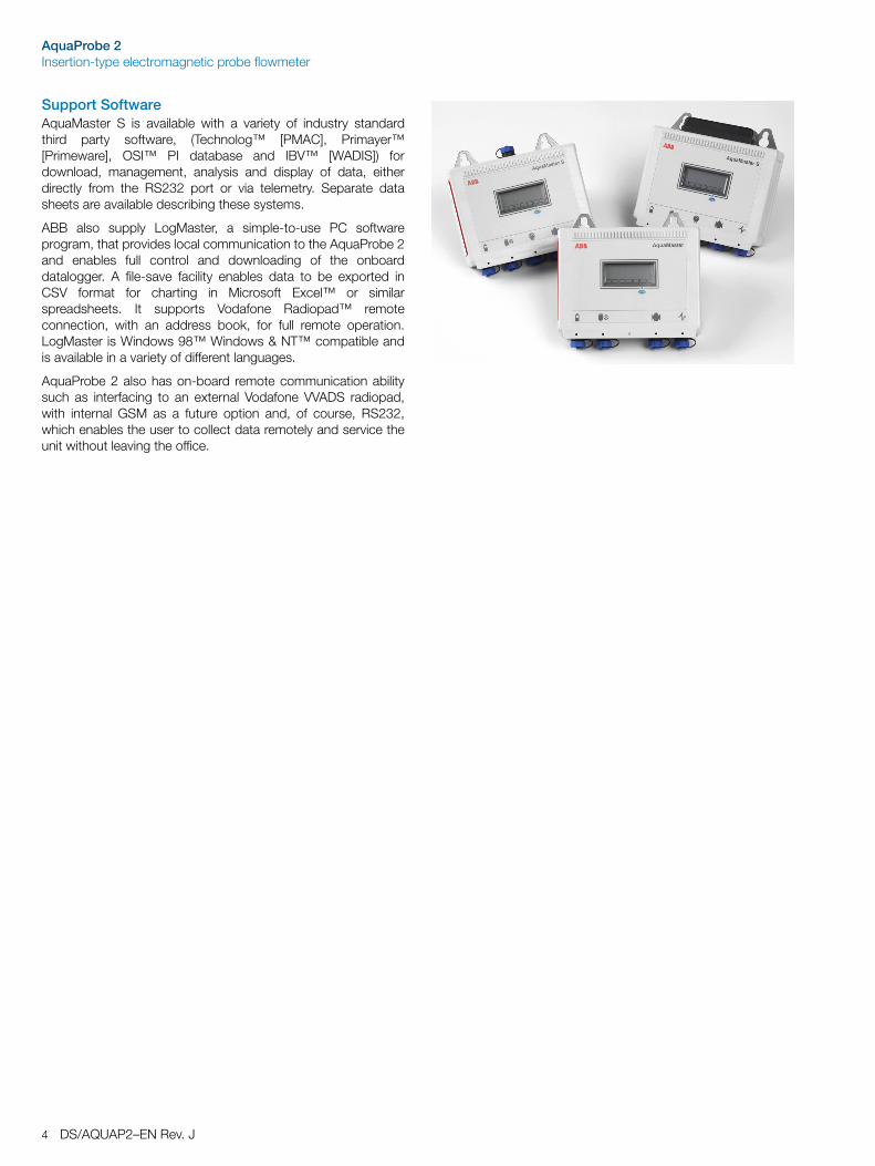
Support SoftwareAquaMaster S is available with a variety of industry standardthird party software, (Technolog™ [PMAC], Primayer™[Primeware], OSI™ PI database and IBV™ [WADIS]) fordownload, management, analysis and display of data, eitherdirectly from the RS232 port or via telemetry. Separate datasheets are available describing these systems.
ABB also supply LogMaster, a simple-to-use PC softwareprogram, that provides local communication to the AquaProbe 2and enables full control and downloading of the onboarddatalogger. A file-save facility enables data to be exported inCSV format for charting in Microsoft Excel™ or similarspreadsheets. It supports Vodafone Radiopad™ remoteconnection, with an address book, for full remote operation.LogMaster is Windows 98™ Windows & NT™ compatible andis available in a variety of different languages.
AquaProbe 2 also has on-board remote communication abilitysuch as interfacing to an external Vodafone VVADS radiopad,with internal GSM as a future option and, of course, RS232,which enables the user to collect data remotely and service theunit without leaving the office.
AquaProbe 2Insertion-type electromagnetic probe flowmeter
DS/AQUAP2–EN Rev. J 5
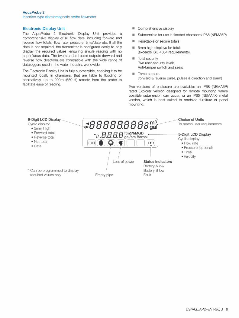
Electronic Display UnitThe AquaProbe 2 Electronic Display Unit provides acomprehensive display of all flow data, including forward andreverse flow totals, flow rate, pressure, time/date etc. If all thedata is not required, the transmitter is configured easily to onlydisplay the required values, ensuring simple reading with nosuperfluous data. The two standard pulse outputs (forward andreverse flow direction) are compatible with the wide range ofdataloggers used in the water industry, worldwide.
The Electronic Display Unit is fully submersible, enabling it to bemounted locally in chambers, that are liable to flooding oralternatively, up to 200m (650 ft) remote from the probe tofacilitate ease of reading.
Comprehensive display
Submersible for use in flooded chambers IP68 (NEMA6P)
Resettable or secure totals
5mm high displays for totals(exceeds ISO 4064 requirements)
Total securityTwo user-security levelsAnti-tamper switch and seals
Three outputs(forward & reverse pulse, pulses & direction and alarm)
Two versions of enclosure are available: an IP68 (NEMA6P)rated Explorer version designed for remote mounting wherepossible submersion can occur, or an IP65 (NEMA4X) metalversion, which is best suited to roadside furniture or panelmounting.
������
�������������������������������
���������������� !�������"%&'��'����#��&()�����*��+)��� ���������)�,�-����������)�.��������)�/���
( %���0��#����������������#��&���������-���������&
!���#���$%���1�����'+������������������
&������ !�������"%&'��'����#��&() �� �����) ���������2�#������3) 1���) 4���'��&
!�#�&�#�#�
�����5�#� �� '�����(%)�#�����6�����&����� 6�����&�6��� ����
AquaProbe 2Insertion-type electromagnetic probe flowmeter
6 DS/AQUAP2–EN Rev. J
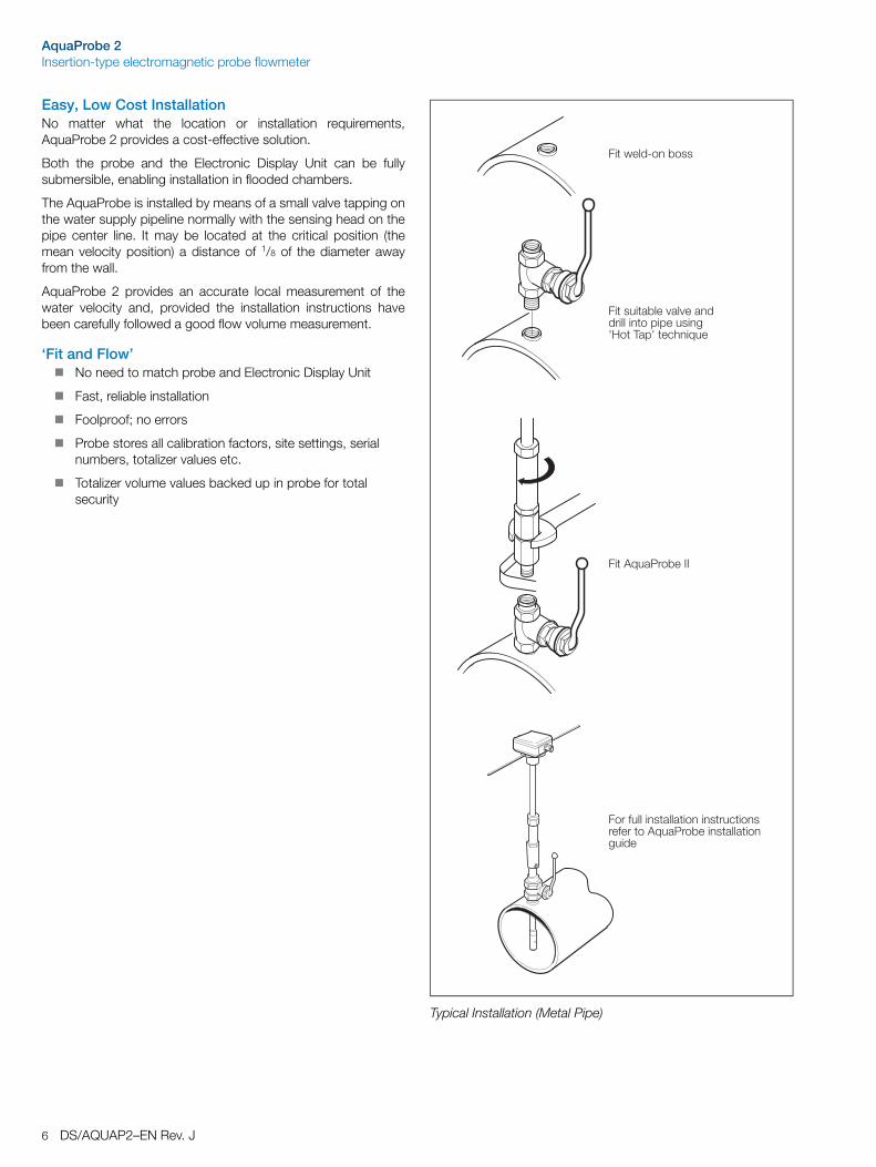
Easy, Low Cost InstallationNo matter what the location or installation requirements,AquaProbe 2 provides a cost-effective solution.
Both the probe and the Electronic Display Unit can be fullysubmersible, enabling installation in flooded chambers.
The AquaProbe is installed by means of a small valve tapping onthe water supply pipeline normally with the sensing head on thepipe center line. It may be located at the critical position (themean velocity position) a distance of 1/8 of the diameter awayfrom the wall.
AquaProbe 2 provides an accurate local measurement of thewater velocity and, provided the installation instructions havebeen carefully followed a good flow volume measurement.
‘Fit and Flow’No need to match probe and Electronic Display Unit
Fast, reliable installation
Foolproof; no errors
Probe stores all calibration factors, site settings, serial numbers, totalizer values etc.
Totalizer volume values backed up in probe for total security
Typical Installation (Metal Pipe)
��� ���7���0���
��������0���-��-����������������#�#�������8*���1�#8���'+�����
����������0����
���5�����������������������'�������5�������������0�������������������
AquaProbe 2Insertion-type electromagnetic probe flowmeter
DS/AQUAP2–EN Rev. J 7
Specification
ProbeMaximum insertion length
300mm (12 in.)
500mm (20 in.)
700mm (25 in.)
1000mm (40 in.)
Pipe sizes200mm to 8000mm (8 in. to 320 in.) nominal bore
ProtectionIP68/NEMA6 (Indefinite submersion down to 10m [30 ft])
Weight<3.5kg (7.7 lb)
AccuracyVelocity
±2% of Rate or ±2mm/s (±0.08 in./s) whichever is the greater
Volume
Refer to ISO 7145-1982 (BS 1042 section 2.2) for details
Flow condition
Fully developed profile in accordance withISO 7145-1982 (BS1042 section 2.2.)
Pressure limitations20bar (295 psi)
Max. Pressure20bar (295 PSI)
Pressure equipment Directive 97/23/ECThis product is applicable in networks for the supply, distribution anddischarge of water and associated equipment and is thereforeexempt
Conductivity>50µS/cm
Connections1 in. BSP
1 in. NPT
1.5 in. BSP
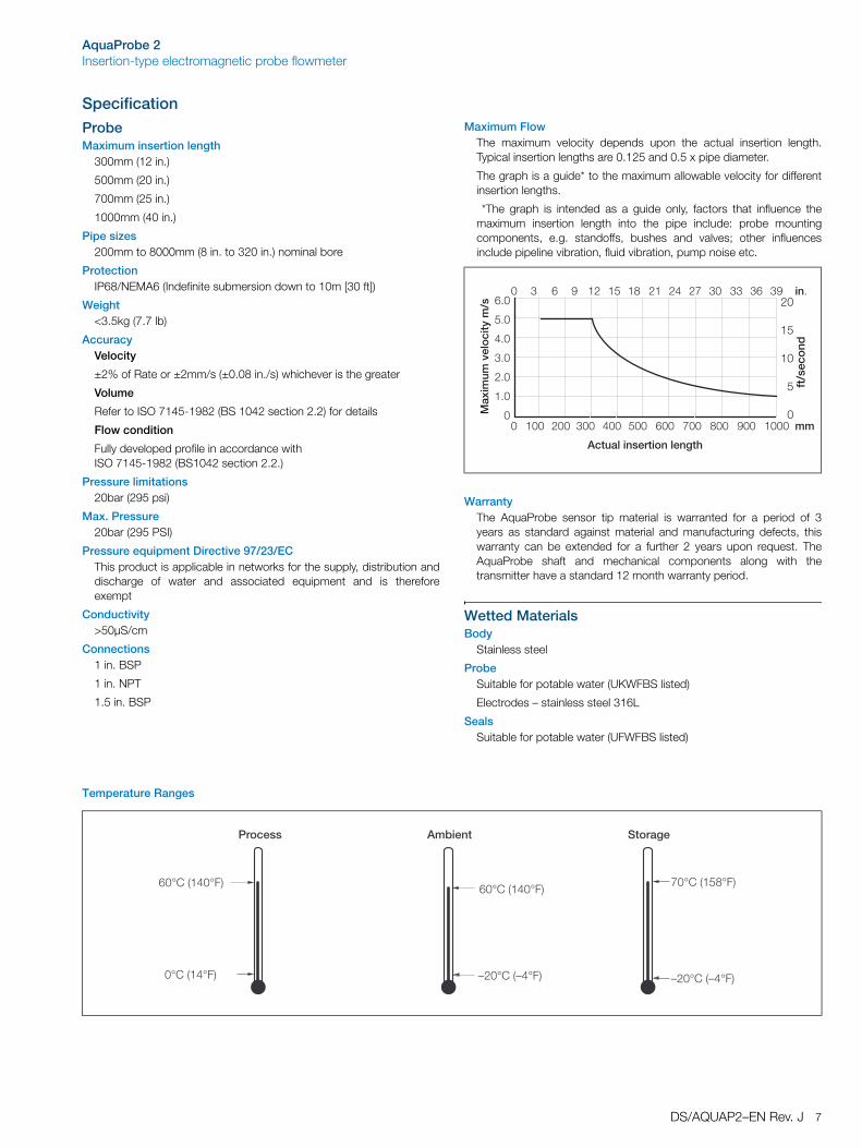
Maximum FlowThe maximum velocity depends upon the actual insertion length.Typical insertion lengths are 0.125 and 0.5 x pipe diameter.
The graph is a guide* to the maximum allowable velocity for differentinsertion lengths.
*The graph is intended as a guide only, factors that influence themaximum insertion length into the pipe include: probe mountingcomponents, e.g. standoffs, bushes and valves; other influencesinclude pipeline vibration, fluid vibration, pump noise etc.
Warranty The AquaProbe sensor tip material is warranted for a period of 3years as standard against material and manufacturing defects, thiswarranty can be extended for a further 2 years upon request. TheAquaProbe shaft and mechanical components along with thetransmitter have a standard 12 month warranty period.
Wetted MaterialsBody
Stainless steel
ProbeSuitable for potable water (UKWFBS listed)
Electrodes – stainless steel 316L
SealsSuitable for potable water (UFWFBS listed)
Temperature Ranges
����� ��� ��� ��� ��� ��� �� 9�� ��� :��
*#�����%������%��%���
�
�;�
�;�
�;�
�;�
�;�
;�
��+����
,���#
��"�
��
��
�:� � : �� �� �� �� �� �9 �� �� � �%;
�
��
�
��
��
�����#�%
)
'������
���<%�2��<3
9�<%�2���<3�<%�2���<3
���#���
�<%�2��<3 ���<%�2��<3
�<%�2���<3
*����%�
AquaProbe 2Insertion-type electromagnetic probe flowmeter
8 DS/AQUAP2–EN Rev. J
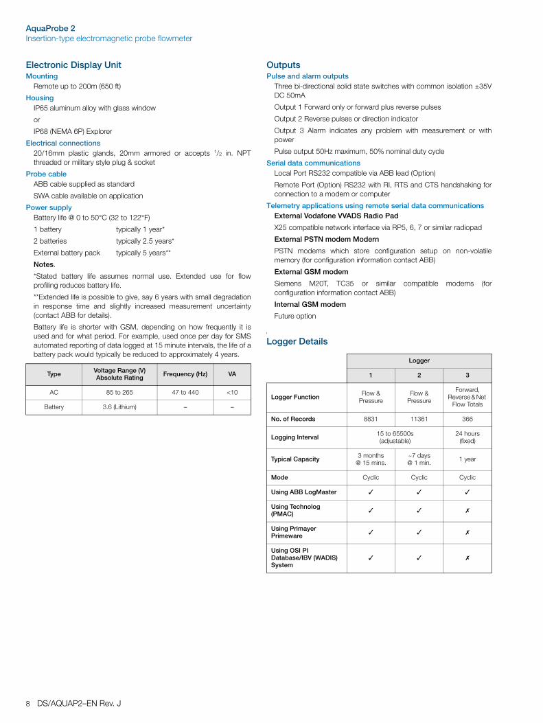
Electronic Display UnitMounting
Remote up to 200m (650 ft)
HousingIP65 aluminum alloy with glass window
or
IP68 (NEMA 6P) Explorer
Electrical connections20/16mm plastic glands, 20mm armored or accepts 1/2 in. NPTthreaded or military style plug & socket
Probe cableABB cable supplied as standard
SWA cable available on application
Power supplyBattery life @ 0 to 50°C (32 to 122°F)
1 battery typically 1 year*
2 batteries typically 2.5 years*
External battery pack typically 5 years**
Notes.
*Stated battery life assumes normal use. Extended use for flowprofiling reduces battery life.
**Extended life is possible to give, say 6 years with small degradationin response time and slightly increased measurement uncertainty(contact ABB for details).
Battery life is shorter with GSM, depending on how frequently it isused and for what period. For example, used once per day for SMSautomated reporting of data logged at 15 minute intervals, the life of abattery pack would typically be reduced to approximately 4 years.
Outputs Pulse and alarm outputs
Three bi-directional solid state switches with common isolation ±35VDC 50mA
Output 1 Forward only or forward plus reverse pulses
Output 2 Reverse pulses or direction indicator
Output 3 Alarm indicates any problem with measurement or withpower
Pulse output 50Hz maximum, 50% nominal duty cycle
Serial data communicationsLocal Port RS232 compatible via ABB lead (Option)
Remote Port (Option) RS232 with RI, RTS and CTS handshaking forconnection to a modem or computer
Telemetry applications using remote serial data communicationsExternal Vodafone VVADS Radio Pad
X25 compatible network interface via RP5, 6, 7 or similar radiopad
External PSTN modem Modern
PSTN modems which store configuration setup on non-volatilememory (for configuration information contact ABB)
External GSM modem
Siemens M20T, TC35 or similar compatible modems (forconfiguration information contact ABB)
Internal GSM modem
Future option
Logger Details
Type Voltage Range (V) Absolute Rating Frequency (Hz) VA
AC 85 to 265 47 to 440 <10
Battery 3.6 (Lithium) – –
Logger
1 2 3
Logger Function Flow & Pressure
Flow & Pressure
Forward, Reverse & Net
Flow Totals
No. of Records 8831 11361 366
Logging Interval 15 to 65500s(adjustable)
24 hours(fixed)
Typical Capacity 3 months @ 15 mins.
~7 days @ 1 min. 1 year
Mode Cyclic Cyclic Cyclic
Using ABB LogMaster
Using Technolog (PMAC)
Using Primayer Primeware
Using OSI PI Database/IBV (WADIS) System
AquaProbe 2Insertion-type electromagnetic probe flowmeter
DS/AQUAP2–EN Rev. J 9
Pressure System – External TransducerPressure range absolute
10bar, 16bar or 300 psi
ConnectionStandard quick-fit male probe
MIL style connector
Operating temperature range–20 to 70°C (–4 to 158°F)
Accuracy (typical)±0.4% of range
Thermal error band (typically 100°C [212°F])±1.5% span
Cable length1, 5, 10 or 20m (3, 16, 32 or 65 ft)
Response Time (Programmable)Minimum1s (mains-powered)
15s (battery-powered) – normal use
3s – for profiling use
LanguagesEnglish
French
German
Spanish
Italian
Dutch
Languages can be changed via Windows download program (contact ABB)
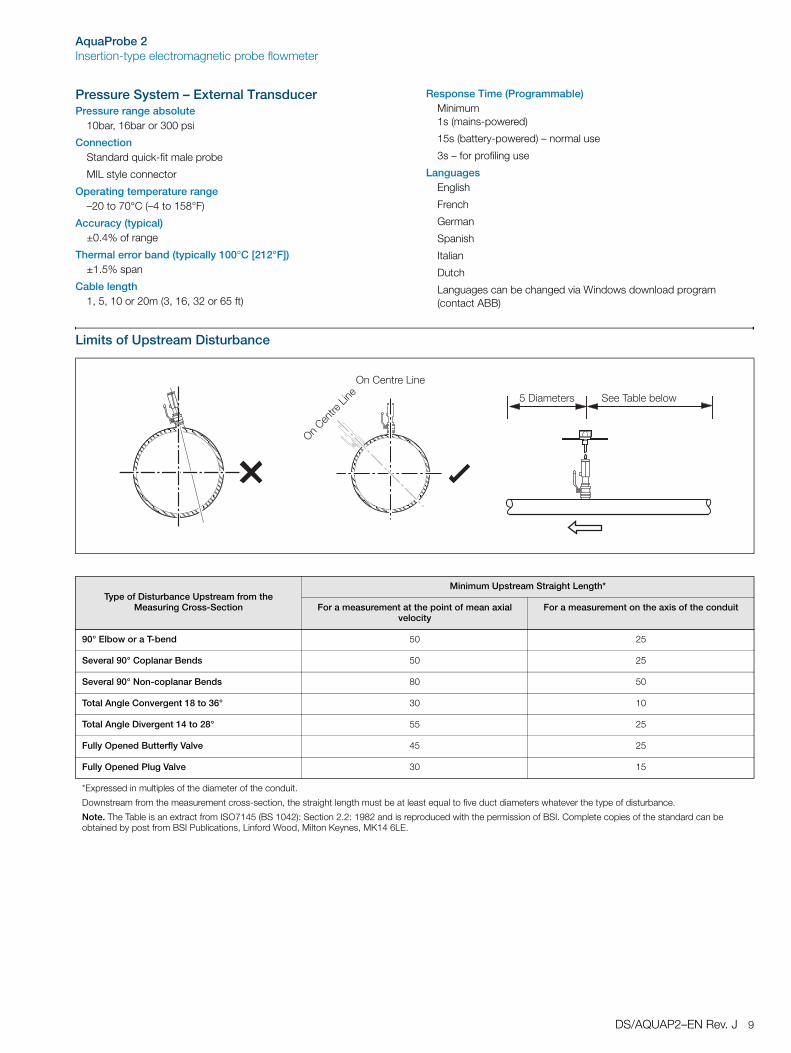
Limits of Upstream Disturbance
Type of Disturbance Upstream from the Measuring Cross-Section
Minimum Upstream Straight Length*
For a measurement at the point of mean axial velocity
For a measurement on the axis of the conduit
90° Elbow or a T-bend 50 25
Several 90° Coplanar Bends 50 25
Several 90° Non-coplanar Bends 80 50
Total Angle Convergent 18 to 36° 30 10
Total Angle Divergent 14 to 28° 55 25
Fully Opened Butterfly Valve 45 25
Fully Opened Plug Valve 30 15
*Expressed in multiples of the diameter of the conduit.
Downstream from the measurement cross-section, the straight length must be at least equal to five duct diameters whatever the type of disturbance.
Note. The Table is an extract from ISO7145 (BS 1042): Section 2.2: 1982 and is reproduced with the permission of BSI. Complete copies of the standard can be obtained by post from BSI Publications, Linford Wood, Milton Keynes, MK14 6LE.
��/�������� =���1�0���0���
$��%������ ���
$��%������ ���
AquaProbe 2Insertion-type electromagnetic probe flowmeter
10 DS/AQUAP2–EN Rev. J
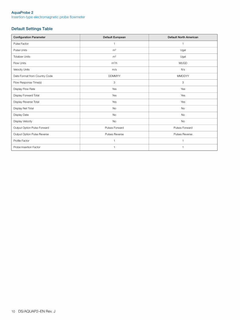
Default Settings Table
Configuration Parameter Default European Default North American
Pulse Factor 1 1
Pulse Units m3 Ugal
Totalizer Units m3 Ugal
Flow Units m3/h MUGD
Velocity Units m/s ft/s
Date Format from Country Code DDMMYY MMDDYY
Flow Response Time(s) 3 3
Display Flow Rate Yes Yes
Display Forward Total Yes Yes
Display Reverse Total Yes Yes
Display Net Total No No
Display Date No No
Display Velocity No No
Output Option Pulse Forward Pulses Forward Pulses Forward
Output Option Pulse Reverse Pulses Reverse Pulses Reverse
Profile Factor 1 1
Probe Insertion Factor 1 1
AquaProbe 2Insertion-type electromagnetic probe flowmeter
DS/AQUAP2–EN Rev. J 11
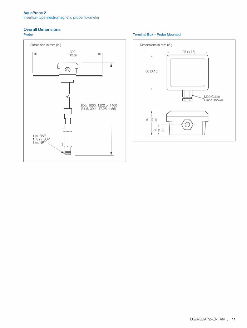
Overall DimensionsProbe Terminal Box – Probe Mounted
Dimension in mm (in.)
���>�����>�������������2��;�>��:;�>��9;��������3
����;�6=���?����;�6=�����;�.�1
���2��;3
Dimensions in mm (in.)
����%�0��@������+� �
:��2�;9�3
��2�;�3
���2�;�3
���2�;��3
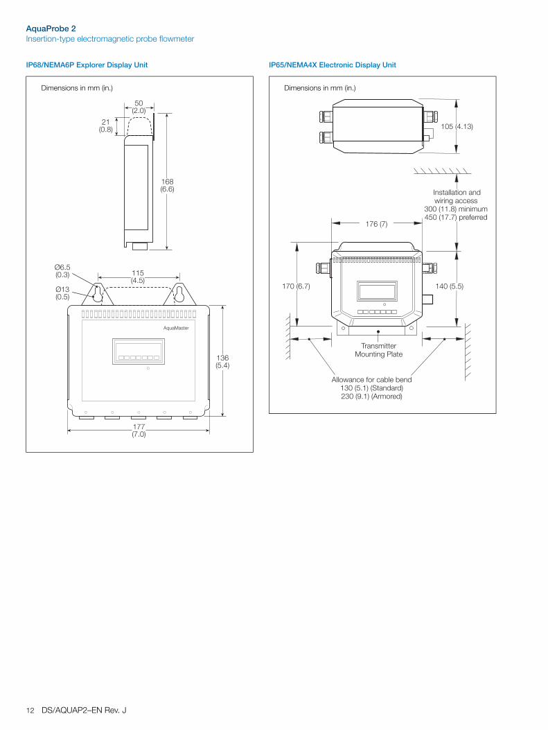
AquaProbe 2Insertion-type electromagnetic probe flowmeter
12 DS/AQUAP2–EN Rev. J
IP68/NEMA6P Explorer Display Unit IP65/NEMA4X Electronic Display Unit
Dimensions in mm (in.)
���2�;�3
�9929;�3
A;�2�;�3
A��2�;�3
��2�;�3
��2;3
��2�;�3
��2�;�3
����������
Dimensions in mm (in.)
����2�;��3
�9�293
����2�;�3�9��2;93
����������������� �������''���
����2��;�3������������2�9;93�#��5�����
1������������������������
���� ��'��5���'�0���0�������2�;�3�2=�������3����2:;�3�2�������3
AquaProbe 2Insertion-type electromagnetic probe flowmeter
DS/AQUAP2–EN Rev. J 13
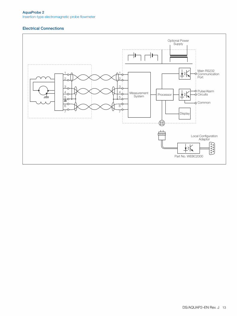
Electrical Connections
/��#��&
�����������=&����
�
�
�
�
9
�
$#��������� ��=�##�&
�����?�����%��'����
%�����
�����,=���%������'���������
���'�����
�
�
�
�
9
�
�'���%��5������������#���
�����.�;�B!6%����
AquaProbe 2Insertion-type electromagnetic probe flowmeter
14 DS/AQUAP2–EN Rev. J
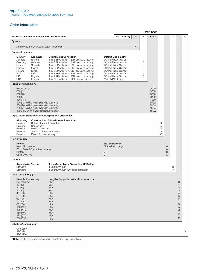
Order Information
Main Code
Insertion-Type Electromagnetic Probe Flowmeter MM/A (PCV) X X XXXX X X X X X
System
AquaProbe Sensor/AquaMaster Transmitter A
Country/Language
CountryAustraliaGermanySpainFranceHollandItalyUKUSA
LanguageEnglishGermanSpanishFrenchDutchItalianEnglishEnglish
Sliding Joint Connection1 in. BSP with 1/8 in. BSP pressure tapping1 in. BSP with 1/8 in. BSP pressure tapping1 in. BSP with 1/8 in. BSP pressure tapping1 in. BSP with 1/8 in. BSP pressure tapping1 in. BSP with 1/8 in. BSP pressure tapping1 in. BSP with 1/8 in. BSP pressure tapping1 in. BSP with 1/8 in. BSP pressure tapping1 in. NPT with 1/8 in. NPT pressure tapping
Default Cable Entry20mm Plastic Glands20mm Plastic Glands20mm Plastic Glands20mm Plastic Glands20mm Plastic Glands20mm Plastic Glands20mm Plastic Glands1/2 in. NPT plugged
ADEFHIGU
Probe Length mm (in.)
Not Required300 (12)500 (20)700 (27)1000 (39)300 (12) With 2-year extended warranty500 (20) With 2-year extended warranty700 (27) With 2-year extended warranty1000 (39) With 2-year extended warranty
0000030005000700100030EW50EW70EW10EW
AquaMaster Transmitter Mounting/Probe Construction
MountingRemoteRemoteRemoteRemoteRemote
Construction of AquaMaster TransmitterSensor & Metal TransmitterSensor onlyMetal TransmitterSensor & Plastic TransmitterPlastic Transmitter only
358AC
Power Supply
PowerNone (Probe only)95 to 240V AC + battery backupBattery95 to 240V AC
No. of BatteriesNone (Probe only)120
0ABL
Options
AquaMaster DisplayStandardStandard
AquaMaster Metal Transmitter IP RatingIP68 (NEMA46P)IP68 (NEMA46P) with extra protection
0A
Cable Length m (ft)*
Remote Probes onlyNot required10 (30)20 (65)30 (95)40 (130)50 (160)60 (195)70 (225)80 (260)100 (325)125 (410)150 (490)175 (570)200 (655)
Lengths Supported with MIL connectorsN/AYesN/AYesN/AN/AN/AN/AN/AN/AN/AN/AN/A
N/A
012345678ABCDE
Labelling/Construction
CompanyABB UKABB USA
01
* Note. Cable type is dependent on Product family and gland type.
AquaProbe 2Insertion-type electromagnetic probe flowmeter
DS/AQUAP2–EN Rev. J 15
Licensing, Trademarks and Copyrights
Microsoft Excel™ and Windows™ are trademarks of the Microsoft Corp.
Technolog™ is a trademark of PMAC
Primayer™ is a trademark of Primeware
OSI™ and IBV™ are trademarks of WADIS
Vodafone Radiopad™ is a trademark of Vodafone
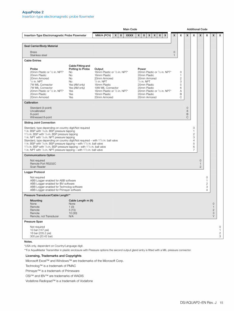
Main Code Additional Code
Insertion-Type Electromagnetic Probe Flowmeter MM/A (PCV) X X XXXX X X X X X X X X X X X X X X
Seal Carrier/Body Material
BrassStainless steel
01
Cable Entries
Probe20mm Plastic or 1/2 in. NPT*20mm Plastic20mm Armored1/2 in. NPT7W MIL Connector7W MIL Connector20mm Plastic or 1/2 in. NPT*20mm Plastic20mm Armored
Cable Fitting and Potting to ProbeNoNoNoNoYes (AM only)Yes (AM only)YesYesYes
Output16mm Plastic or 1/2 in. NPT*16mm Plastic20mm Armored1/2 in. NPT16mm Plastic19W MIL Connector16mm Plastic or 1/2 in. NPT*16mm Plastic20mm Armored
Power20mm Plastic or 1/2 in. NPT*20mm Plastic20mm Armored1/2 in. NPT20mm Plastic20mm Plastic20mm Plastic or 1/2 in. NPT*20mm Plastic20mm Armored
012356ABC
Calibration
Standard (3-point)Uncalibrated8-pointWitnessed 8-point
08BC
Sliding Joint Connection
Standard, type depending on country digit/Not required1 in. BSP with 1/8 in. BSP pressure tapping11/2 in. BSP with 1/8 in. BSP pressure tapping1 in. NPT with 1/8 in. NPT pressure tappingStandard, type depending on country digit/Not required – with 11/2 in. ball valve1 in. BSP with 1/8 in. BSP pressure tapping – with 11/2 in. ball valve11/2 in. BSP with 1/8 in. BSP pressure tapping – with 11/2 in. ball valve1 in. NPT with 1/8 in. NPT pressure tapping – with 11/2 in. ball valve
01234567
Communications Option
Not requiredRemote Port RS232CScan Reader
012
Logger Protocol
Not requiredABB Logger enabled for ABB softwareABB Logger enabled for IBV softwareABB Logger enabled for Technolog softwareABB Logger enabled for Primayer software
01234
Pressure Transducer/Cable Length**
MountingNoneRemoteRemoteRemoteRemote, not Transducer
Cable Length m (ft)None1 (3)5 (15)10 (30)N/A
0123Y
Pressure Span
Not required10 bar (147 psi)16 bar (235.2 psi)300 psi (20.42 bar)
0123
Notes.
*USA only, dependent on Country/Language digit.
**For AquaMaster Transmitter in plastic enclosure with Pressure options the second output gland entry is fitted with a MIL pressure connector.
Contact us
DS
/AQ
UA
P2–
EN
Rev
. J11
.201
0ABB LimitedProcess AutomationOldends LaneStonehouseGloucestershire GL10 3TAUKTel: +44 1453 826 661Fax: +44 1453 829 671
ABB Inc.Process Automation125 E. County Line RoadWarminsterPA 18974USATel: +1 215 674 6000Fax: +1 215 674 7183
www.abb.com
NoteWe reserve the right to make technical changes or modify the contents of this document without prior notice. With regard to purchase orders, the agreed particulars shall prevail. ABB does not accept any responsibility whatsoever for potential errors or possible lack of information in this document.
We reserve all rights in this document and in the subject matter and illustrations contained therein. Any reproduction, disclosure to third parties or utilization of its contents in whole or in parts – is forbidden without prior written consent of ABB.
Copyright© 2010 ABBAll rights reserved
3KXF224202R1001