Embed Size (px)
Citation preview

Operating InstructionD184B121U02
For ConverterModel S4 (BA D184B12
Electromagnetic FlowmeterFSM4000
with AC Magnetic Field ExcitationModel: SE21_/SE41F
2U02)
2 Electromagnetic Flowmeter FSM4000 D184B121U02
Instrument DesignationFSM4000 Model SE21_/SE41F
Operating Instruction
Part No. D184B121U02
Issue: 07.05Revision: 02
Manufacturer:
ABB Automation Products GmbHDransfelder Str. 2
37079 Göttingen, Germany
Phone: +49 (0) 55 19 05- 0Fax: +49 (0) 55 19 05- 777
© Copyright 2005 by ABB Automation Products GmbHWe reserve the right to technical amendments.
This document is protected by copyright. Information in this document is intended only to assist the userin the safe and efficient operation of the equipment. Its contents are not to be reproduced in full or part with-out prior approval of the legal owner.
Contents
1 Flowmeter Primary and Converter Coordination .............................................. 5
1.1 Application Range .................................................................................................................51.2 Model Number Coordination ................................................................................................5
1.3 Operating Instruction .............................................................................................................5
1.4 Condensed Instructions ........................................................................................................51.5 Metering System Specifications ............................................................................................5
2 Overview, Flowmeter Primary Designs ............................................................. 6
3 Functional Description ........................................................................................ 7
3.1 External Data Storage Module FRAM (Ferroelectric Nonvolatile Random Access Memory) ............................................................8
4 Safety Information ............................................................................................... 9
4.1 Basic Safety Requirements ...................................................................................................94.1.1 Instrument Safety Standards .................................................................................................9
4.1.2 Correct Usage .......................................................................................................................9
4.1.3 Specification Limits ...............................................................................................................94.1.4 Allowable Fluids (Liquids) ...................................................................................................10
4.1.5 Safety Signs and Symbols, Name Plate and CE-Mark .......................................................10
4.1.6 Name Plate Specifications ..................................................................................................114.1.7 Personnel Qualifications .....................................................................................................11
4.1.8 User Responsibilities ...........................................................................................................11
4.1.9 Possible Dangers During Transport ....................................................................................124.1.10 Possible Dangers During Installation ..................................................................................12
4.1.11 Possible Dangers During Electrical Installation ...................................................................12
4.1.12 Possible Dangers During Operation ....................................................................................124.1.13 Possible Dangers During Inspection and Maintenance ......................................................13
4.1.14 Returns ................................................................................................................................13
5 Assembly and Installation ................................................................................ 14
5.1 Inspection ............................................................................................................................14
5.2 Flowmeter Primary Installation Requirements ....................................................................145.2.1 Flowmeter Primary Installation ............................................................................................175.2.2 Assembly and Installation for Protection Class IP 68 ..........................................................21
5.2.3 Installation of High Temperature Design Flowmeter Primaries ...........................................22
5.2.4 Installations in Larger Size Pipelines ..................................................................................23
5.3 Material Loads .....................................................................................................................245.3.1 General ...............................................................................................................................24
5.3.2 Process Connections ..........................................................................................................24
5.3.2.1 DIN-Flanges SS No. 1.4571 [316Ti] to DN 600 ..................................................................24
5.3.2.2 ANSI-Flanges SS No. 1.4571 [316Ti] to DN 300 [12”] (CL150/300) to 1000 [40”] (CL150) ..............................................................................................................24
5.3.2.3 DIN-Flanges Steel to DN 600 ..............................................................................................25
5.3.2.4 ANSI-Flanges Steel to DN 300 [12”] (CL150/300) to 1000 [40”] (CL150) ...........................25
5.3.2.5 JIS 10K-B2210 Flanges SS No. 1.4571 [316Ti] or Steel ...................................................25
5.3.2.6 DIN Flanges SS No. 1.4571 [316Ti] ≤ DN 1000 ..................................................................26
5.3.2.7 DIN Flanges Steel ≤ DN 1000 .............................................................................................26
5.3.2.8 Wafer Design Series 2000 ..................................................................................................27
6 Electrical Connections ...................................................................................... 28
6.1 Grounding ...........................................................................................................................286.1.1 Supply Power Connections .................................................................................................326.1.2 Magnet Coil Supply Connections ........................................................................................32
6.1.3 Power ..................................................................................................................................32
D184B121U02 Electromagnetic Flowmeter FSM4000 3
Contents
6.1.4 Signal Cable Connections ...................................................................................................32
6.1.5 Interconnection Diagram ....................................................................................................33
6.1.6 Connection Area .................................................................................................................34
7 Replaceable Parts, Flowmeter Primary ........................................................... 35
7.1 Replaceable Parts, Connection Box, Stainless Steel ≤ DN 100 [4"] ...................................357.2 Replaceable Parts, Connection Box, Aluminum ≤ DN1000 [40”] ........................................36
8 Start-Up .............................................................................................................. 37
8.1 Preliminary Checks .............................................................................................................378.2 Zero Adjustment ..................................................................................................................37
8.3 Detector „Empty pipe“ .........................................................................................................37
8.4 Gaskets ...............................................................................................................................378.5 Maintenance .......................................................................................................................38
9 Appendix, Approvals ........................................................................................ 39
9.1 EU-Declaration of Conformity PED for Flanged Instruments .............................................39
9.2 EU-Declaration of Conformity PED for Wafer Design Instruments and Instruments with Variable Process Connections ................................................................40
9.3 Instrument EMC-Directive 89/336/EWG and Low Voltage Directive 73/23/EEC .................41
4 Electromagnetic Flowmeter FSM4000 D184B121U02
1 Flowmeter Primary and Converter Coordination
1 Flowmeter Primary and Converter Coordination
1.1 Application Range
The electromagnetic flowmeter provides an economical and precise method for metering the flowrate of liq-uids, slurries, pastes and sludges with an electrical conductivity ≥ 20 µS/cm (option ≥ 0.5 µS/cm). The me-tering system is especially well suited for fast changing processes, two phase liquids, and continuous orpulsating flows (piston pump operation).
1.2 Model Number Coordination
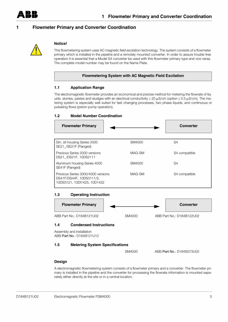
1.3 Operating Instruction
ABB Part No.: D184B121U02 SM4000 ABB Part No.: D184B122U02
1.4 Condensed Instructions
Assembly and installationABB Part No.: D184B121U12
1.5 Metering System Specifications
SM4000 ABB Part No.: D184S073U02
Design
A electromagnetic flowmetering system consists of a flowmeter primary and a converter. The flowmeter pri-mary is installed in the pipeline and the converter for processing the flowrate information is mounted sepa-rately either directly at the site or in a central location.
!Notice!
This flowmetering system uses AC magnetic field excitation technology. The system consists of a flowmeterprimary which is installed in the pipeline and a remotely mounted converter. In order to assure trouble freeoperation it is essential that a Model S4 converter be used with this flowmeter primary type and vice versa.The complete model number may be found on the Name Plate.
Flowmetering System with AC Magnetic Field Excitation
Flowmeter Primary Converter
Flowmeter Primary Converter
Stn. stl housing Series 2000 SM4000 S4SE21_/SE21F (Flanged)
Previous Series 2000 versions MAG-SM S4 compatibleDS21_/DS21F, 10DS2111
Aluminum housing Series 4000 SM4000 S4SE41F (Flanged)
Previous Series 3000/4000 versions MAG-SM S4 compatibleDS41F/DS44F, 10DS3111/2,10DS3121, 10DI1425, 10D1422
D184B121U02 Electromagnetic Flowmeter FSM4000 5
2 Overview, Flowmeter Primary Designs
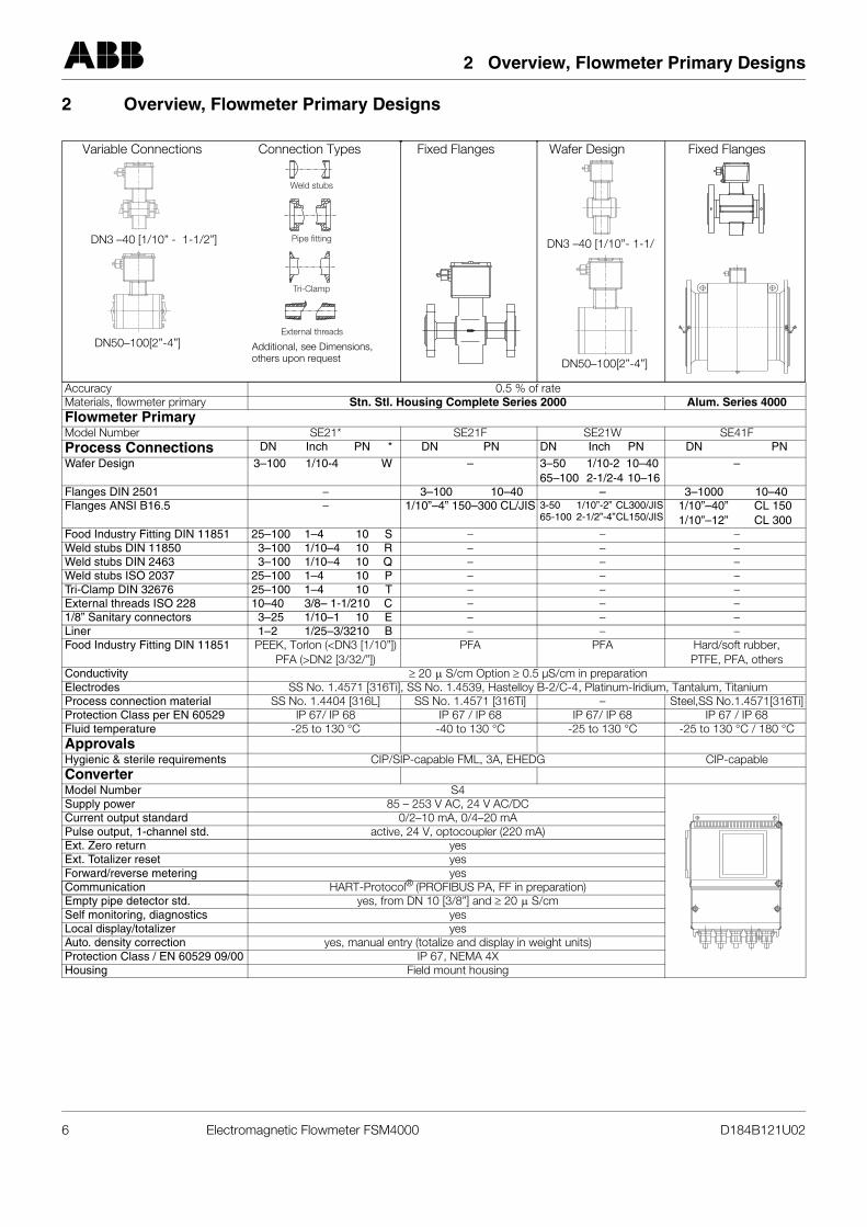
2 Overview, Flowmeter Primary Designs
Accuracy 0.5 % of rateMaterials, flowmeter primary Stn. Stl. Housing Complete Series 2000 Alum. Series 4000Flowmeter PrimaryModel Number SE21* SE21F SE21W SE41FProcess Connections DN Inch PN * DN PN DN Inch PN DN PNWafer Design 3–100 1/10-4 W – 3–50 1/10-2 10–40
65–100 2-1/2-4 10–16–
Flanges DIN 2501 – 3–100 10–40 – 3–1000 10–40Flanges ANSI B16.5 – 1/10”–4” 150–300 CL/JIS 3-50 1/10”-2” CL300/JIS
65-100 2-1/2”-4”CL150/JIS1/10”–40” CL 1501/10”–12” CL 300
Food Industry Fitting DIN 11851 25–100 1–4 10 S – – –Weld stubs DIN 11850 3–100 1/10–4 10 R – – –Weld stubs DIN 2463 3–100 1/10–4 10 Q – – –Weld stubs ISO 2037 25–100 1–4 10 P – – –Tri-Clamp DIN 32676 25–100 1–4 10 T – – –External threads ISO 228 10–40 3/8– 1-1/210 C – – –1/8” Sanitary connectors 3–25 1/10–1 10 E – – –Liner 1–2 1/25–3/3210 B – – –Food Industry Fitting DIN 11851 PEEK, Torlon (<DN3 [1/10”])
PFA (>DN2 [3/32/”])PFA PFA Hard/soft rubber,
PTFE, PFA, othersConductivity ≥ 20 S/cm Option ≥ 0.5 µS/cm in preparationElectrodes SS No. 1.4571 [316Ti], SS No. 1.4539, Hastelloy B-2/C-4, Platinum-Iridium, Tantalum, TitaniumProcess connection material SS No. 1.4404 [316L] SS No. 1.4571 [316Ti] – Steel,SS No.1.4571[316Ti]Protection Class per EN 60529 IP 67/ IP 68 IP 67 / IP 68 IP 67/ IP 68 IP 67 / IP 68Fluid temperature -25 to 130 °C -40 to 130 °C -25 to 130 °C -25 to 130 °C / 180 °CApprovalsHygienic & sterile requirements CIP/SIP-capable FML, 3A, EHEDG CIP-capableConverterModel Number S4Supply power 85 – 253 V AC, 24 V AC/DCCurrent output standard 0/2–10 mA, 0/4–20 mAPulse output, 1-channel std. active, 24 V, optocoupler (220 mA)Ext. Zero return yesExt. Totalizer reset yesForward/reverse metering yesCommunication HART-Protocol® (PROFIBUS PA, FF in preparation)Empty pipe detector std. yes, from DN 10 [3/8”] and ≥ 20 S/cmSelf monitoring, diagnostics yesLocal display/totalizer yesAuto. density correction yes, manual entry (totalize and display in weight units)Protection Class / EN 60529 09/00 IP 67, NEMA 4XHousing Field mount housing
Weld stubs
Pipe fitting
Tri�Clamp
External threads
Fixed Flanges Fixed FlangesWafer DesignVariable Connections
DN3 –40 [1/10”- 1-1/
DN50–100[2”-4”]
DN3 –40 [1/10” - 1-1/2”]
DN50–100[2”-4”]
Connection Types
Additional, see Dimensions, others upon request
µ
µ
6 Electromagnetic Flowmeter FSM4000 D184B121U02
3 Functional Description
3 Functional Description
ABB Automation Products Electromagnetic Flowmeters "EMF" are the ideal flow metering instruments for allliquids, slurries, pastes or sludges with a conductivity above a specific minimum value. The instrumentsmeter accurately, produce no additional pressure drop, contain no moving or protruding parts and are wearfree and corrosion resistant. Installations can be made in any existing pipeline.
ABB Automation Products EMFs have been field proven over many years and are the flowmeter of choicein the Chemical industry, Municipal Water and Waste Water treatment facilities, Food industry and the Paperindustry.
Principle of Operation
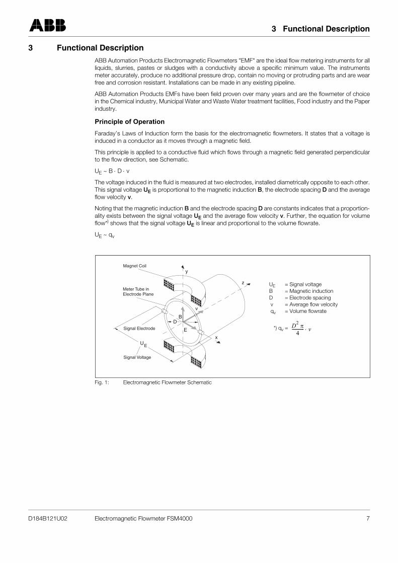
Faraday’s Laws of Induction form the basis for the electromagnetic flowmeters. It states that a voltage isinduced in a conductor as it moves through a magnetic field.
This principle is applied to a conductive fluid which flows through a magnetic field generated perpendicularto the flow direction, see Schematic.
UE ~ B ⋅ D ⋅ v
The voltage induced in the fluid is measured at two electrodes, installed diametrically opposite to each other.This signal voltage UE is proportional to the magnetic induction B, the electrode spacing D and the averageflow velocity v.
Noting that the magnetic induction B and the electrode spacing D are constants indicates that a proportion-ality exists between the signal voltage UE and the average flow velocity v. Further, the equation for volumeflow*) shows that the signal voltage UE is linear and proportional to the volume flowrate.
UE ~ qv
Fig. 1: Electromagnetic Flowmeter Schematic
UE
y
z
x
BD
E
v
Magnet Coil
Meter Tube inElectrode Plane
Signal Electrode
Signal Voltage
*) qv = D2 π4
------------ v⋅
UE = Signal voltageB = Magnetic inductionD = Electrode spacing v = Average flow velocity qv = Volume flowrate
D184B121U02 Electromagnetic Flowmeter FSM4000 7
3 Functional Description
3.1 External Data Storage Module FRAM (Ferroelectric Nonvolatile Random Access Memory)
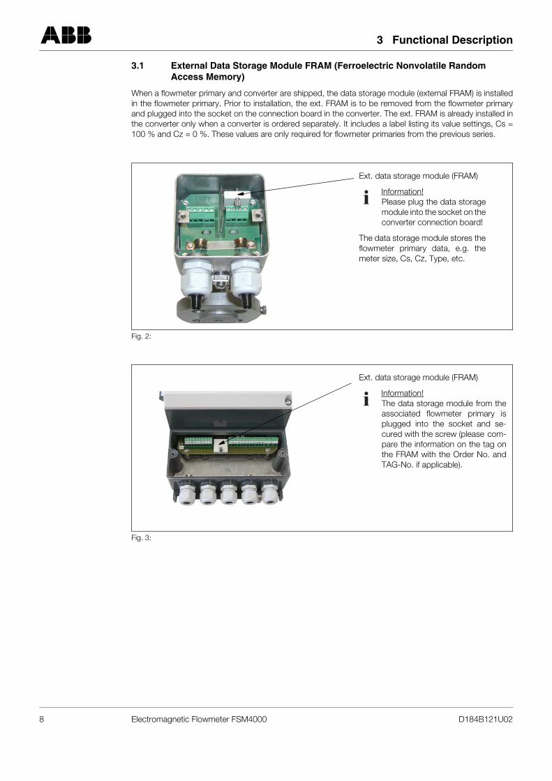
When a flowmeter primary and converter are shipped, the data storage module (external FRAM) is installedin the flowmeter primary. Prior to installation, the ext. FRAM is to be removed from the flowmeter primaryand plugged into the socket on the connection board in the converter. The ext. FRAM is already installed inthe converter only when a converter is ordered separately. It includes a label listing its value settings, Cs =100 % and Cz = 0 %. These values are only required for flowmeter primaries from the previous series.
Fig. 2:
Fig. 3:
Ext. data storage module (FRAM)
Information!Please plug the data storagemodule into the socket on theconverter connection board!
The data storage module stores theflowmeter primary data, e.g. themeter size, Cs, Cz, Type, etc.
Ext. data storage module (FRAM)
Information!The data storage module from theassociated flowmeter primary isplugged into the socket and se-cured with the screw (please com-pare the information on the tag onthe FRAM with the Order No. andTAG-No. if applicable).
8 Electromagnetic Flowmeter FSM4000 D184B121U02

4 Safety Information
4 Safety Information
4.1 Basic Safety Requirements
4.1.1 Instrument Safety Standards
• This equipment corresponds to the fundamental safety requirements of the Pressure Equipment Direc-tive and is designed using the latest state-of-the-art technology. It was tested at the factory, based on the safety requirements, and was shipped in proper working order. In order to maintain this condition over the life of the instrument the requirements described in this Operating Instruction must be observed and followed.
• The instruments satisfy the EMC-Requirements in EN 61326 /NAMUR NE 21.
• All instrument parameters (including the totalizer values) are permanently stored in an FRAM during a power outage or when the power is turned off. The instrument is immediately operational once the power is turned on again.
4.1.2 Correct Usage
This instrument is used
• to meter during transport of electrically conductive liquids, slurries, pastes and sludges
• the actual volume flowrate or
• the mass flowrate (at constant pressure / temperature) when the mass units parameter is selected
Correct usage includes the following:
• installations compatible with the specification limits
• observing and following the information relative to allowable fluids
• observing and following the statements in the Operating Instruction
• observing and following the information in the accompanying documents (Data Sheet)
The following equipment uses are not permitted:
• installation as a flexible adapter in piping, e.g. to compensate for pipe offsets, pipe vibrations, pipe expansions etc.
• use as a climbing aid, e.g. for assembly purposes,
• use as a support for external loads, e.g. as a bracket for pipelines etc.
• addition of materials or parts by painting (covering the Name Plate), welding or soldering
• removal of materials, e.g. by drilling into the housing
• repairs, modifications and additions and the installation of replacement parts. These are only permitted using the procedures described in this Operating Instruction. Additional tasks must be approved by ABB. We accept no liability for unauthorized tasks.
The operation, service and maintenance requirements in this Operating Instruction must be observed. Themanufacturer assumes no responsibility for damages resulting from improper or prohibited use.
4.1.3 Specification Limits
The instrument is designed exclusively for use within the specifications listed on the Name Plate and in theOperating Instruction. The following limits must be observed:
• the allowable pressure (PS) and the allowable fluid temperature (TS) must be ≤ than the pressure-tem-perature values (p/T-Ratings) listed in the Operating Instruction.
D184B121U02 Electromagnetic Flowmeter FSM4000 9
4 Safety Information
• the maximum operating temperature defined in the Instrument Data Sheet may not be exceeded.
• the allowable ambient temperature range defined in the Instrument Data Sheet may not be exceeded
• housing Protection Class IP 67 or IP 68 per EN60529
• graphite must not applied to the seals because, under certain circumstances, it may cause an electri-cally conductive coating to form on the inside of the flowmeter.
• the flowmeter primary may not be operated in the vicinity of strong electromagnetic fields, e.g., motors, pumps, transformers, etc. A minimum spacing of approx. ca. 100 cm should be maintained. For instal-lation on or to steel parts (e.g. steel brackets) a minimum spacing of approx. ca. 100 mm should be maintained. (These values were established using IEC801-2 or IEC TC 77B (SEC 101) as a guide).
4.1.4 Allowable Fluids (Liquids)
• Only fluids (liquids) may be metered for which assurance is available, from either published technical information or operational experience of the user, that the chemical and physical properties of the fluid wetted parts in the flowmeter (signal and or grounding electrodes, liner materials, connection fittings and grounding plates if used) will not be adversely affected during the life of the flowmeter.
• Fluids (liquids) with unknown or abrasive properties may only be metered if the user performs periodic inspections to assure that the safety parameters of the flowmeter have not been compromised.
• The specifications on the Name Plate are to be observed.
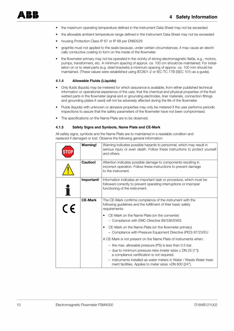
4.1.5 Safety Signs and Symbols, Name Plate and CE-Mark
All safety signs, symbols and the Name Plate are to maintained in a readable condition and replaced if damaged or lost. Observe the following general information:
Warning! Warning indicates possible hazards to personnel, which may result in serious injury or even death. Follow these instructions to protect yourselfand others.
Caution! Attention indicates possible damage to components resulting in incorrect operation. Follow these instructions to prevent damage to the instrument.
Important! Information indicates an important task or procedure, which must be followed correctly to prevent operating interruptions or improper functioning of the instrument.
CE-Mark The CE-Mark confirms compliance of the instrument with the following guidelines and the fulfillment of their basic safety requirements:
• CE-Mark on the Name Plate (on the converter)– Compliance with EMC-Directive 89/336/EWG
• CE-Mark on the Name Plate (on the flowmeter primary)– Compliance with Pressure Equipment Directive (PED) 97/23/EU
A CE-Mark is not present on the Name Plate of instruments when:
– the max. allowable pressure (PS) is less than 0.5 bar.– due to minimum pressure risks (meter sizes ≤ DN 25 [1“])
a compliance certification is not required.– instruments installed as water meters in Water / Waste Water treat-
ment facilities. Applies to meter sizes >DN 600 [24”].
STOP
!
10 Electromagnetic Flowmeter FSM4000 D184B121U02
4 Safety Information
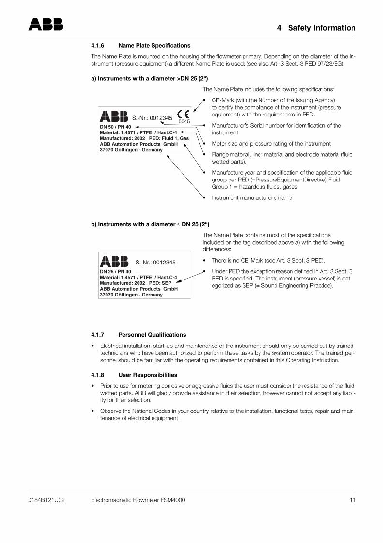
4.1.6 Name Plate Specifications
The Name Plate is mounted on the housing of the flowmeter primary. Depending on the diameter of the in-strument (pressure equipment) a different Name Plate is used: (see also Art. 3 Sect. 3 PED 97/23/EG)
a) Instruments with a diameter >DN 25 (2“)
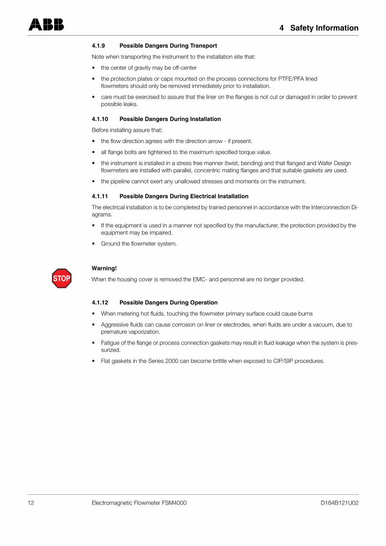
b) Instruments with a diameter ≤ DN 25 (2“)
4.1.7 Personnel Qualifications
• Electrical installation, start-up and maintenance of the instrument should only be carried out by trained technicians who have been authorized to perform these tasks by the system operator. The trained per-sonnel should be familiar with the operating requirements contained in this Operating Instruction.
4.1.8 User Responsibilities
• Prior to use for metering corrosive or aggressive fluids the user must consider the resistance of the fluid wetted parts. ABB will gladly provide assistance in their selection, however cannot not accept any liabil-ity for their selection.
• Observe the National Codes in your country relative to the installation, functional tests, repair and main-tenance of electrical equipment.
The Name Plate includes the following specifications:
• CE-Mark (with the Number of the issuing Agency) to certify the compliance of the instrument (pressure equipment) with the requirements in PED.
• Manufacturer’s Serial number for identification of the instrument.
• Meter size and pressure rating of the instrument
• Flange material, liner material and electrode material (fluid wetted parts).
• Manufacture year and specification of the applicable fluid group per PED (=PressureEquipmentDirective) Fluid Group 1 = hazardous fluids, gases
• Instrument manufacturer’s name
The Name Plate contains most of the specifications included on the tag described above a) with the following differences:
• There is no CE-Mark (see Art. 3 Sect. 3 PED).
• Under PED the exception reason defined in Art. 3 Sect. 3 PED is specified. The instrument (pressure vessel) is cat-egorized as SEP (= Sound Engineering Practice).
��� S.-Nr.: 00123450045
DN 50 / PN 40Material: 1.4571 / PTFEManufactured: 2002 PED: Fluid 1, GasABB Automation Products GmbH37070 Göttingen - Germany
/ Hast.C-4
��� S.-Nr.: 0012345
DN 25 / PN 40Material: 1.4571 / PTFEManufactured: 2002 PED: SEPABB Automation Products GmbH37070 Göttingen - Germany
/ Hast.C-4
D184B121U02 Electromagnetic Flowmeter FSM4000 11
4 Safety Information
4.1.9 Possible Dangers During Transport
Note when transporting the instrument to the installation site that:
• the center of gravity may be off-center
• the protection plates or caps mounted on the process connections for PTFE/PFA lined flowmeters should only be removed immediately prior to installation.
• care must be exercised to assure that the liner on the flanges is not cut or damaged in order to prevent possible leaks.
4.1.10 Possible Dangers During Installation
Before installing assure that:
• the flow direction agrees with the direction arrow - if present.
• all flange bolts are tightened to the maximum specified torque value.
• the instrument is installed in a stress free manner (twist, bending) and that flanged and Wafer Design flowmeters are installed with parallel, concentric mating flanges and that suitable gaskets are used.
• the pipeline cannot exert any unallowed stresses and moments on the instrument.
4.1.11 Possible Dangers During Electrical Installation
The electrical installation is to be completed by trained personnel in accordance with the Interconnection Di-agrams.
• If the equipment is used in a manner not specified by the manufacturer, the protection provided by the equipment may be impaired.
• Ground the flowmeter system.
4.1.12 Possible Dangers During Operation
• When metering hot fluids, touching the flowmeter primary surface could cause burns
• Aggressive fluids can cause corrosion on liner or electrodes, when fluids are under a vacuum, due to premature vaporization.
• Fatigue of the flange or process connection gaskets may result in fluid leakage when the system is pres-surized.
• Flat gaskets in the Series 2000 can become brittle when exposed to CIP/SIP procedures.
STOPWarning!
When the housing cover is removed the EMC- and personnel are no longer provided.
12 Electromagnetic Flowmeter FSM4000 D184B121U02
4 Safety Information
4.1.13 Possible Dangers During Inspection and Maintenance
• Prior to removing the instrument from the pipeline assure that the instrument and the pipeline or reser-voirs are depressurized.
• Before opening the instrument ascertain whether hazardous material had been present in the flowme-ter. Hazardous residues may still be present in the flowmeter and exit when it is opened.
• The flange bolts and nuts are to be secured to prevent loosening due to pipeline vibrations.
• During the periodic inspection specified in the Pressure Equipment Directive check the following ele-ments of the instrument (pressure equipment):– the walls / liners of the pressure equipment subjected to the fluid pressure– its operation– its seals– for wear (corrosion, abrasion)
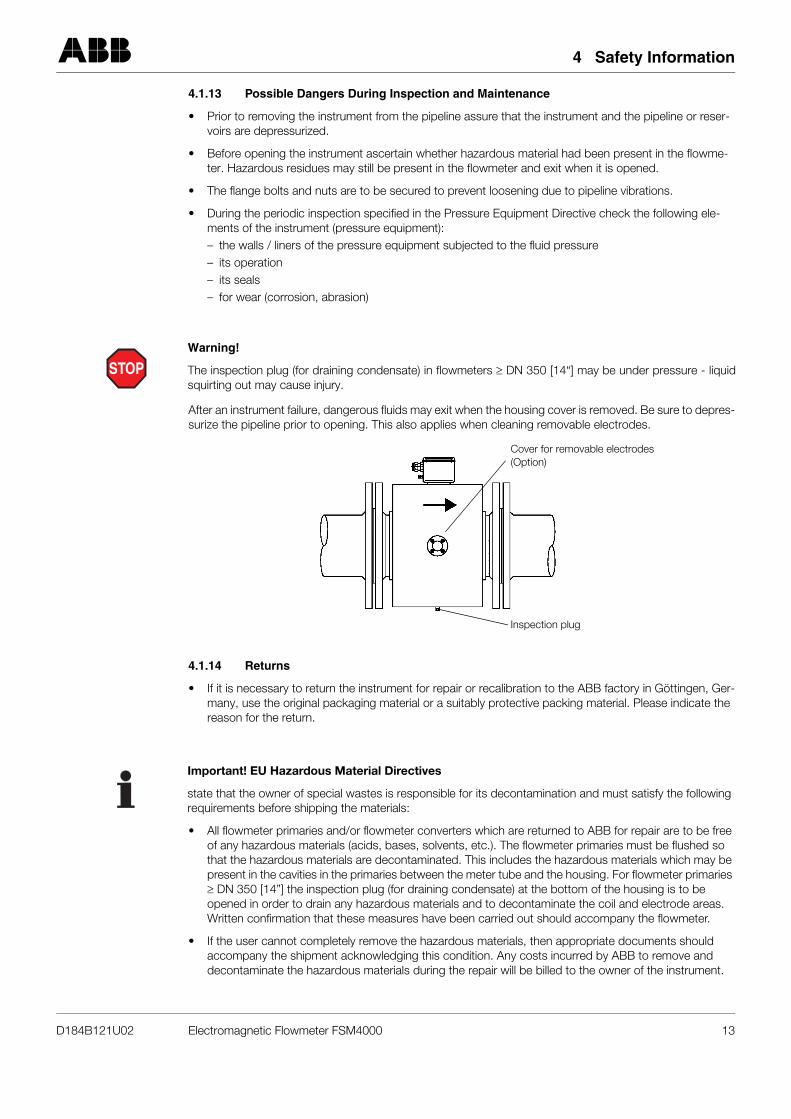
After an instrument failure, dangerous fluids may exit when the housing cover is removed. Be sure to depres-surize the pipeline prior to opening. This also applies when cleaning removable electrodes.
4.1.14 Returns
• If it is necessary to return the instrument for repair or recalibration to the ABB factory in Göttingen, Ger-many, use the original packaging material or a suitably protective packing material. Please indicate the reason for the return.
• All flowmeter primaries and/or flowmeter converters which are returned to ABB for repair are to be free of any hazardous materials (acids, bases, solvents, etc.). The flowmeter primaries must be flushed so that the hazardous materials are decontaminated. This includes the hazardous materials which may be present in the cavities in the primaries between the meter tube and the housing. For flowmeter primaries ≥ DN 350 [14”] the inspection plug (for draining condensate) at the bottom of the housing is to be opened in order to drain any hazardous materials and to decontaminate the coil and electrode areas. Written confirmation that these measures have been carried out should accompany the flowmeter.
• If the user cannot completely remove the hazardous materials, then appropriate documents should accompany the shipment acknowledging this condition. Any costs incurred by ABB to remove and decontaminate the hazardous materials during the repair will be billed to the owner of the instrument.
STOPWarning!
The inspection plug (for draining condensate) in flowmeters ≥ DN 350 [14“] may be under pressure - liquidsquirting out may cause injury.
Cover for removable electrodes(Option)
Inspection plug
Important! EU Hazardous Material Directives
state that the owner of special wastes is responsible for its decontamination and must satisfy the followingrequirements before shipping the materials:
D184B121U02 Electromagnetic Flowmeter FSM4000 13
5 Assembly and Installation
5 Assembly and Installation
5.1 Inspection
Before installing the electromagnetic flowmeter system check for mechanical damage due to possible mis-handling during shipment. All claims for damage are to be made promptly to the shipper before installing theflowmeter.
5.2 Flowmeter Primary Installation Requirements
The flowmeter primary should not be installed in the vicinity of strong electromagnetic fields. A minimum dis-tance of 100 cm should be maintained.
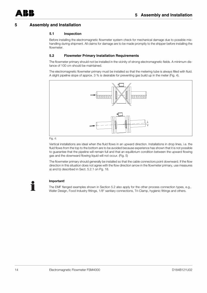
The electromagnetic flowmeter primary must be installed so that the metering tube is always filled with fluid.A slight pipeline slope of approx. 3 % is desirable for preventing gas build up in the meter (Fig. 4).
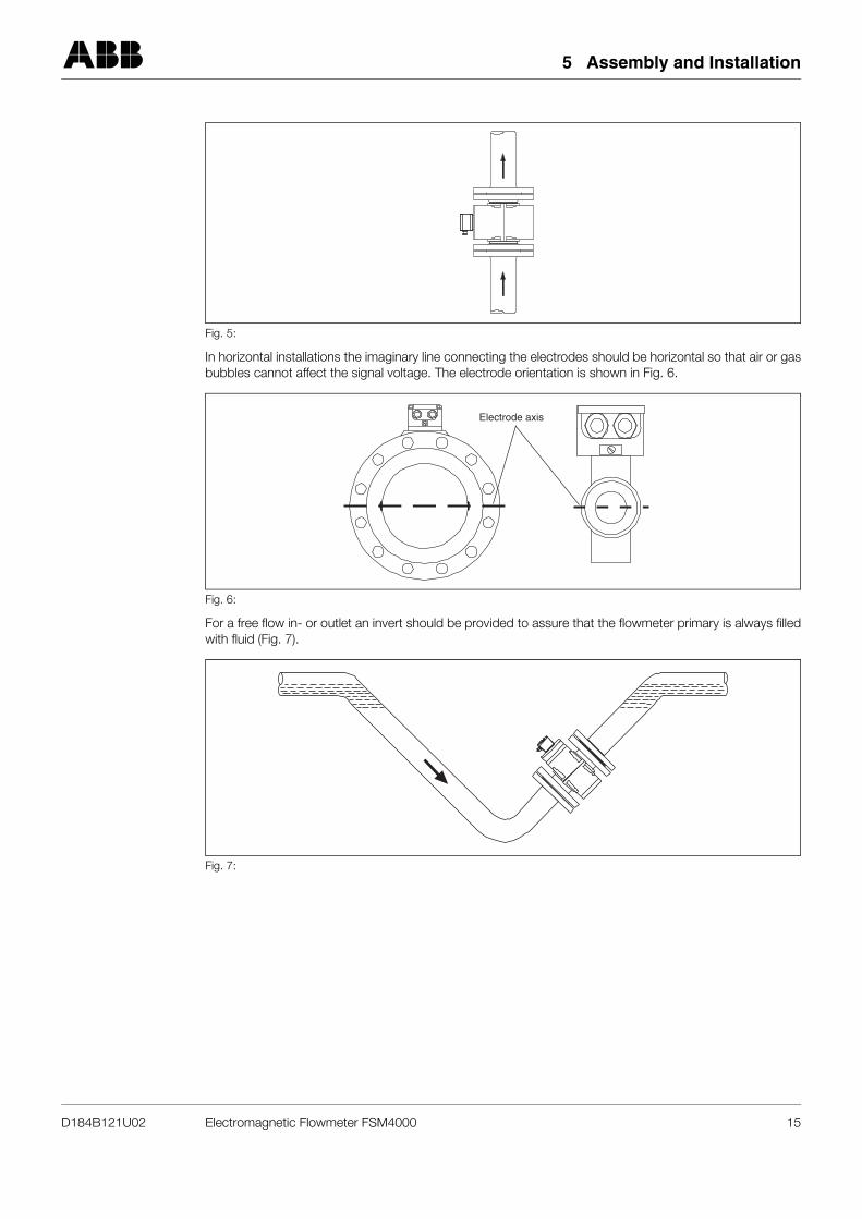
Vertical installations are ideal when the fluid flows in an upward direction. Installations in drop lines, i.e. thefluid flows from the top to the bottom are to be avoided because experience has shown that it is not possibleto guarantee that the pipeline will remain full and that an equilibrium condition between the upward flowinggas and the downward flowing liquid will not occur. (Fig. 5)
The flowmeter primary should generally be installed so that the cable connectors point downward. If the flowdirection in this situation does not agree with the flow direction arrow in the flowmeter primary, use measuresa) and b) described in Sect. 5.2.1 on Pg. 18.
Fig. 4:
Important!
The EMF flanged examples shown in Section 5.2 also apply for the other process connection types, e.g.,Wafer Design, Food Industry fittings, 1/8“ sanitary connections, Tri-Clamp, hygienic fittings and others.
14 Electromagnetic Flowmeter FSM4000 D184B121U02
5 Assembly and Installation
In horizontal installations the imaginary line connecting the electrodes should be horizontal so that air or gasbubbles cannot affect the signal voltage. The electrode orientation is shown in Fig. 6.
For a free flow in- or outlet an invert should be provided to assure that the flowmeter primary is always filledwith fluid (Fig. 7).
Fig. 5:
Fig. 6:
Fig. 7:
Electrode axis
D184B121U02 Electromagnetic Flowmeter FSM4000 15
5 Assembly and Installation
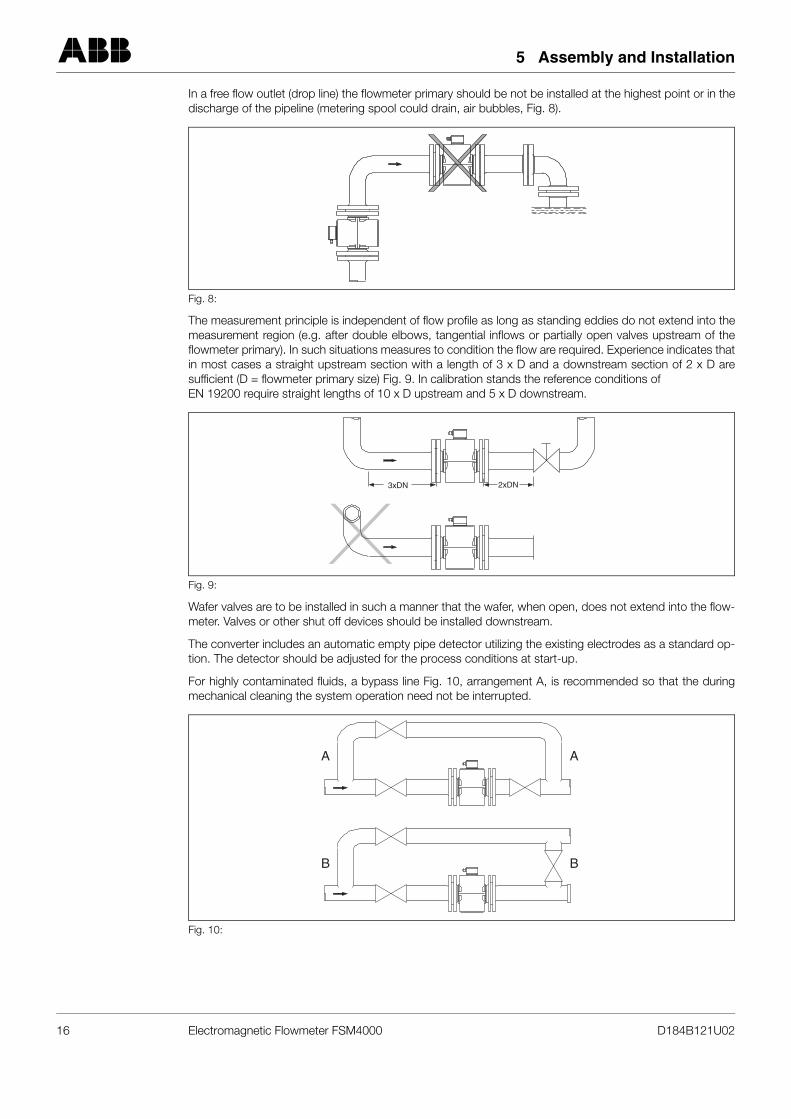
In a free flow outlet (drop line) the flowmeter primary should be not be installed at the highest point or in thedischarge of the pipeline (metering spool could drain, air bubbles, Fig. 8).
The measurement principle is independent of flow profile as long as standing eddies do not extend into themeasurement region (e.g. after double elbows, tangential inflows or partially open valves upstream of theflowmeter primary). In such situations measures to condition the flow are required. Experience indicates thatin most cases a straight upstream section with a length of 3 x D and a downstream section of 2 x D aresufficient (D = flowmeter primary size) Fig. 9. In calibration stands the reference conditions of EN 19200 require straight lengths of 10 x D upstream and 5 x D downstream.
Wafer valves are to be installed in such a manner that the wafer, when open, does not extend into the flow-meter. Valves or other shut off devices should be installed downstream.
The converter includes an automatic empty pipe detector utilizing the existing electrodes as a standard op-tion. The detector should be adjusted for the process conditions at start-up.
For highly contaminated fluids, a bypass line Fig. 10, arrangement A, is recommended so that the duringmechanical cleaning the system operation need not be interrupted.
Fig. 8:
Fig. 9:
Fig. 10:
3xDN 2xDN
A
B
A
B
16 Electromagnetic Flowmeter FSM4000 D184B121U02
5 Assembly and Installation
When insulation or coating of the electrodes is to be expected, a bypass line as shown in Fig. 10, arrange-ment B, should be utilized to simplify the cleaning operation.
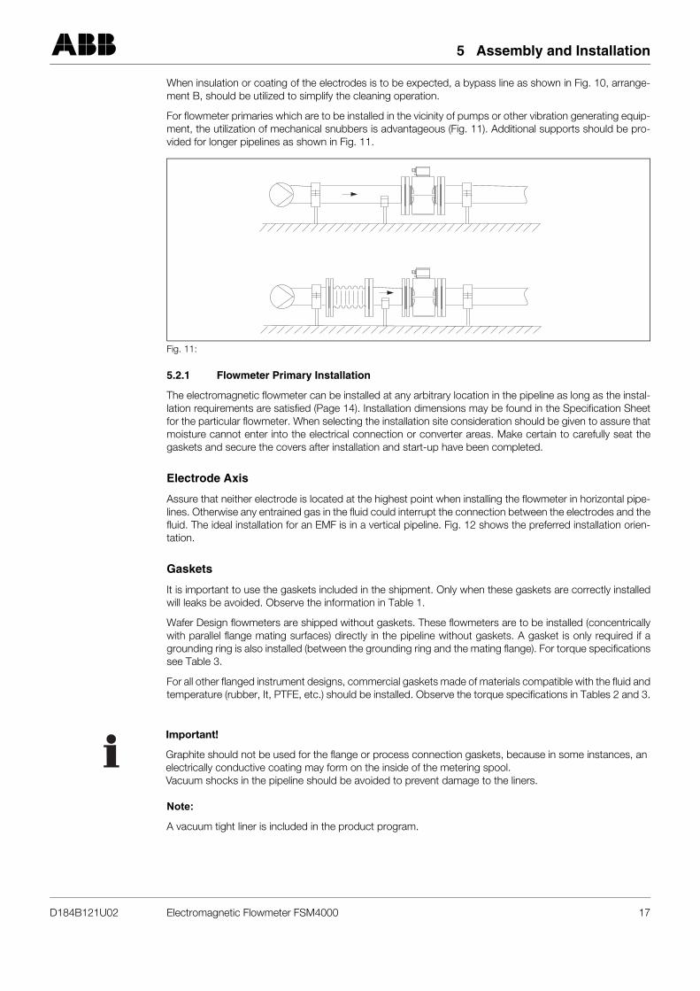
For flowmeter primaries which are to be installed in the vicinity of pumps or other vibration generating equip-ment, the utilization of mechanical snubbers is advantageous (Fig. 11). Additional supports should be pro-vided for longer pipelines as shown in Fig. 11.
5.2.1 Flowmeter Primary Installation
The electromagnetic flowmeter can be installed at any arbitrary location in the pipeline as long as the instal-lation requirements are satisfied (Page 14). Installation dimensions may be found in the Specification Sheetfor the particular flowmeter. When selecting the installation site consideration should be given to assure thatmoisture cannot enter into the electrical connection or converter areas. Make certain to carefully seat thegaskets and secure the covers after installation and start-up have been completed.
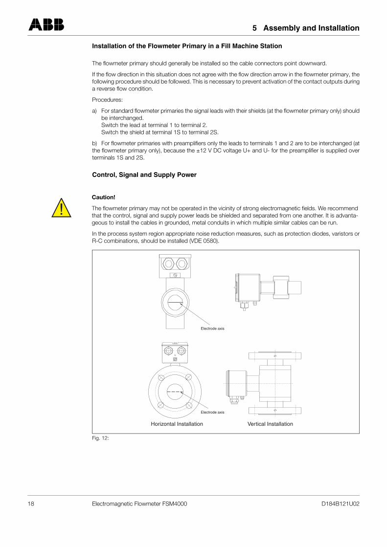
Electrode Axis
Assure that neither electrode is located at the highest point when installing the flowmeter in horizontal pipe-lines. Otherwise any entrained gas in the fluid could interrupt the connection between the electrodes and thefluid. The ideal installation for an EMF is in a vertical pipeline. Fig. 12 shows the preferred installation orien-tation.
Gaskets
It is important to use the gaskets included in the shipment. Only when these gaskets are correctly installedwill leaks be avoided. Observe the information in Table 1.
Wafer Design flowmeters are shipped without gaskets. These flowmeters are to be installed (concentricallywith parallel flange mating surfaces) directly in the pipeline without gaskets. A gasket is only required if agrounding ring is also installed (between the grounding ring and the mating flange). For torque specificationssee Table 3.
For all other flanged instrument designs, commercial gaskets made of materials compatible with the fluid andtemperature (rubber, It, PTFE, etc.) should be installed. Observe the torque specifications in Tables 2 and 3.
Note:
A vacuum tight liner is included in the product program.
Fig. 11:
Important!
Graphite should not be used for the flange or process connection gaskets, because in some instances, anelectrically conductive coating may form on the inside of the metering spool. Vacuum shocks in the pipeline should be avoided to prevent damage to the liners.
D184B121U02 Electromagnetic Flowmeter FSM4000 17
5 Assembly and Installation
Installation of the Flowmeter Primary in a Fill Machine Station
The flowmeter primary should generally be installed so the cable connectors point downward.
If the flow direction in this situation does not agree with the flow direction arrow in the flowmeter primary, thefollowing procedure should be followed. This is necessary to prevent activation of the contact outputs duringa reverse flow condition.
Procedures:
a) For standard flowmeter primaries the signal leads with their shields (at the flowmeter primary only) shouldbe interchanged.Switch the lead at terminal 1 to terminal 2.Switch the shield at terminal 1S to terminal 2S.
b) For flowmeter primaries with preamplifiers only the leads to terminals 1 and 2 are to be interchanged (atthe flowmeter primary only), because the ±12 V DC voltage U+ and U- for the preamplifier is supplied overterminals 1S and 2S.
Control, Signal and Supply Power
In the process system region appropriate noise reduction measures, such as protection diodes, varistors orR-C combinations, should be installed (VDE 0580).
!Caution!
The flowmeter primary may not be operated in the vicinity of strong electromagnetic fields. We recommendthat the control, signal and supply power leads be shielded and separated from one another. It is advanta-geous to install the cables in grounded, metal conduits in which multiple similar cables can be run.
Fig. 12:
Vertical InstallationHorizontal Installation
Electrode axis
Electrode axis
18 Electromagnetic Flowmeter FSM4000 D184B121U02
5 Assembly and Installation
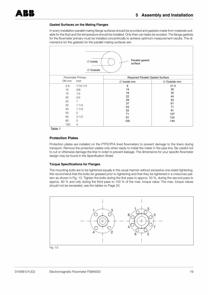
Gasket Surfaces on the Mating Flanges
In every installation parallel mating flange surfaces should be provided and gaskets made from materials suit-able for the fluid and the temperature should be installed. Only then can leaks be avoided. The flange gasketsfor the flowmeter primary must be installed concentrically to achieve optimum measurement results. The di-mensions for the gaskets for the parallel mating surfaces are:
Protection Plates
Protection plates are installed on the PTFE/PFA lined flowmeters to prevent damage to the liners duringtransport. Remove the protection plates only when ready to install the meter in the pipe line. Be careful notto cut or otherwise damage the liner in order to prevent leakage. The dimensions for your specific flowmeterdesign may be found in the Specification Sheet.
Torque Specifications for Flanges
The mounting bolts are to be tightened equally in the usual manner without excessive one-sided tightening.We recommend that the bolts be greased prior to tightening and that they be tightened in a crisscross pat-tern as shown in Fig. 13. Tighten the bolts during the first pass to approx. 50 %, during the second pass toapprox. 80 % and only during the third pass to 100 % of the max. torque value. The max. torque valuesshould not be exceeded, see the tables on Page 20.
Flowmeter PrimaryDN mm Inch
Required Parallel Gasket Surface∅ Inside mm ∅ Outside mm
3-6 1/10-1/410 3/815 1/220 3/425 132 1-1/440 1-1/250 265 2-1/280 3100 4
8141822293743527181
100
21.535354452617191
107124149
Table 1
Fig. 13:
∅ Outside
∅ Inside Parallel gasketsurface
4
4
8
7
31 1 5
2 26
3
D184B121U02 Electromagnetic Flowmeter FSM4000 19
5 Assembly and Installation
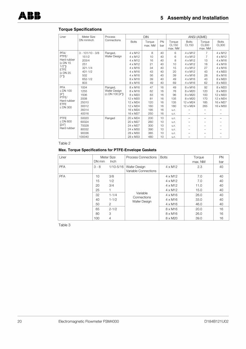
Torque Specifications
Table 2
Max. Torque Specifications for PTFE-Envelope Gaskets
Table 3
Liner Meter SizeDN mmInch
Process Connections
DIN ANSI (ASME)Bolts Torque
max. NMPNbar
Torque CL150
max. NM
BoltsCL150
Torque CL300
max. NM
BoltsCL300
PFA/PTFE/Hard rubber(≥ DN 15 1/2”])ETFE(≥ DN 25 [1”])
3 - 101/10 - 3/8151/2203/4251321-1/4401-1/2502652-1/2803
Flanged,Wafer Design
4 x M124 x M124 x M124 x M124 x M164 x M164 x M168 x M168 x M16
81016213443563949
404040404040404040
668
101520394969
4 x M124 x M124 x M124 x M124 x M124 x M124 x M164 x M164 x M16
77
13182743284362
4 x M124 x M124 x M164 x M164 x M164 x M208 x M168 x M208 x M20
PFA≤ DN 100 [4"]PTFE/Hard rubberETFE≤ DN 300
100412551506200825010300123501440016
Flanged,Wafer Design(≤ DN 100 [4"])
8 x M168 x M168 x M20
12 x M2012 x M2412 x M2416 x M2416 x M27
47628381
120160195250
1616161616161616
497696
135135180u.r.u.r.
8 x M168 x M208 x M208 x M20
12 x M2412 x M24
––
92120100170185265
––
8 x M208 x M20
12 x M2012 x M2416 x M2716 x M30
––
PTFE≤ DN 600 [24”]Hard rubber
5002060024700288003290036
100040
Flanged 20 x M2420 x M2724 x M2724 x M3028 x M3028 x M33
200260300390385480
101010101010
u.r.u.r.u.r.u.r.u.r.u.r.
––––––
––––––
––––––
Liner Meter SizeDN mm Inch
Process Connections Bolts Torquemax. NM
PNbar
PFA 3 - 8 1/10-5/16 Wafer DesignVariable Connections
4 x M12 2.3 40
PFA 10 3/815 1/220 3/425 1
Variable ConnectionsWafer Design
4 x M124 x M124 x M124 x M12
7.07.0
11.015.0
40404040
32 1-1/440 1-1/250 2
4 x M164 x M164 x M16
26.033.046.0
404040
65 2-1/280 3
100 4
8 x M168 x M168 x M20
20.026.039.0
161616
20 Electromagnetic Flowmeter FSM4000 D184B121U02

5 Assembly and Installation
5.2.2 Assembly and Installation for Protection Class IP 68
For Protection Class IP 68 the continuous submergence level can be 5 m. Protection Class IP 68 can beadded after the meter has been installed, possible only for horizontal installations with remote mounted con-verters, (or can be ordered shipped from the factory with the cable potted) - because the connection boxcan be potted for IP 68 after start-up has completed.
The potting material (2-component PU) included with the shipment is packaged in a protection sleeve withappropriate safety information. This information should be noted before starting the potting procedure.
Preparation:
• Only apply the potting material after the installation has been completed successfully, avoid introducing moisture and check all connections for proper seating and tightness.
• Do not overfill the connection box - keep potting material away from O-ring and seal/groove.
• Avoid putting potting material into the protection pipe for ½" NPT installations (if used).
Procedure:
• Cut open the potting material protection sleeve - see packaging
• Open the clamp between the potting and hardener materials
• Knead both materials until they are thoroughly mixed
• Cut open one corner of the package (working time is 30 minutes)
• Carefully fill the connection box with mixed potting material until the connection cables are covered
• Allow a few hours to elapse for the potting material to harden before carefully reinstalling the cover
• Dispose of the packing and desiccant materials and in an environmentally safe manner
STOPWarning!
The potting material is hazardous - take appropriate safety precautions!Safety information: R20, R36/37/38, R42/43
Vapors are harmful, avoid inhaling, avoid direct skin contact, eye irritant!Safety suggestions: P4, S23-A, S24/25, S26, S37, S38
Wear suitable gloves, provide good ventilation, observe manufacturer’s instructions before handling the pot-ting material.
Fig. 14: PU-Potting Material in a 200gr. Package, Part No.: D141B038U01
Potting material
Clamp
Package
Desiccant bag
D184B121U02 Electromagnetic Flowmeter FSM4000 21
5 Assembly and Installation
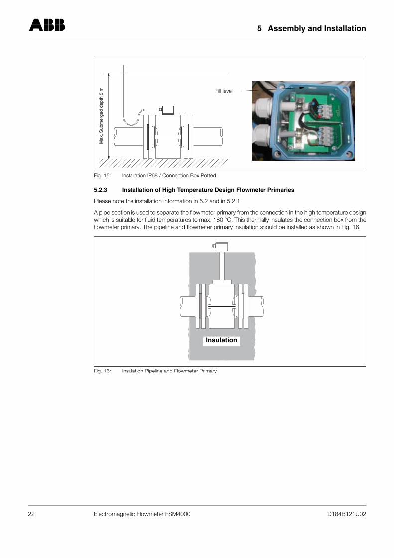
5.2.3 Installation of High Temperature Design Flowmeter Primaries
Please note the installation information in 5.2 and in 5.2.1.
A pipe section is used to separate the flowmeter primary from the connection in the high temperature designwhich is suitable for fluid temperatures to max. 180 °C. This thermally insulates the connection box from theflowmeter primary. The pipeline and flowmeter primary insulation should be installed as shown in Fig. 16.
Fig. 15: Installation IP68 / Connection Box Potted
Fig. 16: Insulation Pipeline and Flowmeter Primary
Max
. Sub
mer
ged
dept
h 5
m Fill level
Insulation
22 Electromagnetic Flowmeter FSM4000 D184B121U02
5 Assembly and Installation
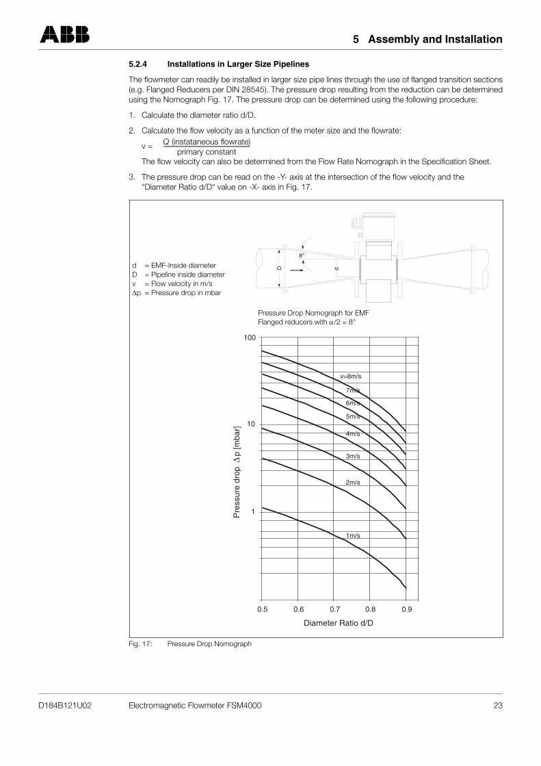
5.2.4 Installations in Larger Size Pipelines
The flowmeter can readily be installed in larger size pipe lines through the use of flanged transition sections(e.g. Flanged Reducers per DIN 28545). The pressure drop resulting from the reduction can be determinedusing the Nomograph Fig. 17. The pressure drop can be determined using the following procedure:
1. Calculate the diameter ratio d/D.
2. Calculate the flow velocity as a function of the meter size and the flowrate:
v =
The flow velocity can also be determined from the Flow Rate Nomograph in the Specification Sheet.
3. The pressure drop can be read on the -Y- axis at the intersection of the flow velocity and the “Diameter Ratio d/D“ value on -X- axis in Fig. 17.
Fig. 17: Pressure Drop Nomograph
Q (instataneous flowrate)primary constant
---------------------------------------------------------
D d
8°
100
10
1
0.5 0.6 0.7
Diameter Ratio d/D
0.8 0.9
v=8m/s
7m/s
6m/s
5m/s
4m/s
3m/s
2m/s
1m/s
Pre
ssur
e dr
opp
[mba
r]
d = EMF-Inside diameterD = Pipeline inside diameterv = Flow velocity in m/s∆p = Pressure drop in mbar
Pressure Drop Nomograph for EMFFlanged reducers with α/2 = 8°
D184B121U02 Electromagnetic Flowmeter FSM4000 23
5 Assembly and Installation
5.3 Material Loads
5.3.1 General
5.3.2 Process Connections
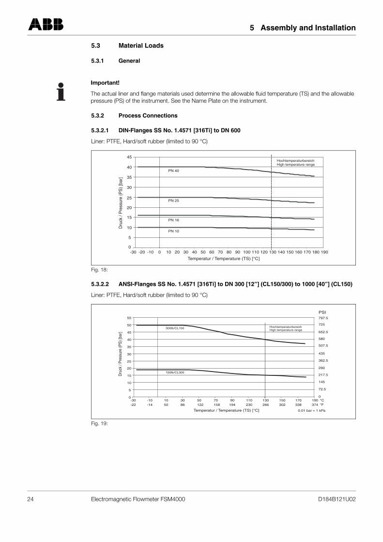
5.3.2.1 DIN-Flanges SS No. 1.4571 [316Ti] to DN 600
Liner: PTFE, Hard/soft rubber (limited to 90 °C)
5.3.2.2 ANSI-Flanges SS No. 1.4571 [316Ti] to DN 300 [12”] (CL150/300) to 1000 [40”] (CL150)
Liner: PTFE, Hard/soft rubber (limited to 90 °C)
Important!
The actual liner and flange materials used determine the allowable fluid temperature (TS) and the allowablepressure (PS) of the instrument. See the Name Plate on the instrument.
Fig. 18:
Fig. 19:
Temperatur / Temperature (TS) [°C]
Dru
ck /
Pre
ssur
e (P
S) [
bar]
HochtemperaturbereichHigh temperature range
PN 40
PN 25
PN 16
PN 10
0
5
10
15
20
25
30
35
40
45
-30 -20 -10 0 10 20 30 40 50 60 70 80 90 100 110 120 130 140 150 160 170 180 190
Temperatur / Temperature (TS) [°C]
Dru
ck /
Pre
ssur
e (P
S) [
bar]
300lb/CL150
150lb/CL300
HochtemperaturbereichHigh temperature range
0
5
10
15
20
25
30
35
40
45
50
55
-30-22
-10-14
1050
3086
50122
70158
90194
110230
130266
150302
170338
190 °C°F374
0.01 bar = 1 kPa
797.5
PSI
725
652.5
580
507.5
435
362.5
290
217.5
145
72.5
0
24 Electromagnetic Flowmeter FSM4000 D184B121U02
5 Assembly and Installation
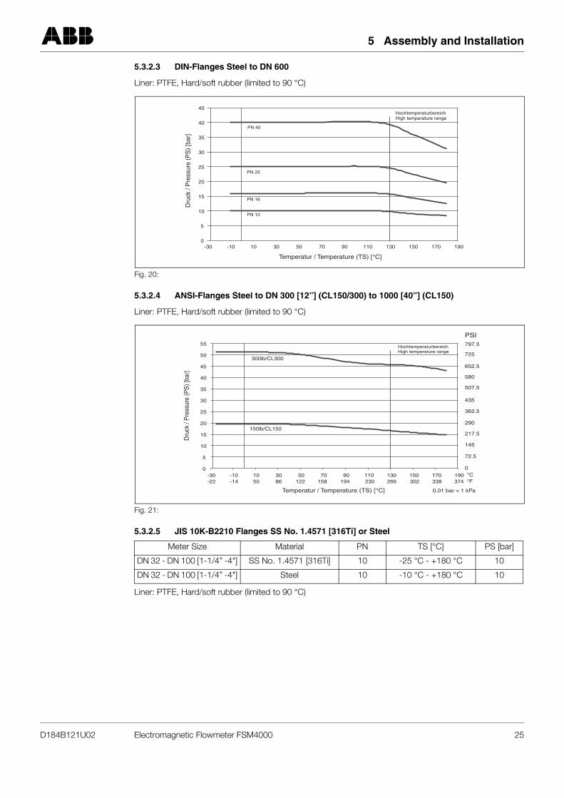
5.3.2.3 DIN-Flanges Steel to DN 600
Liner: PTFE, Hard/soft rubber (limited to 90 °C)
5.3.2.4 ANSI-Flanges Steel to DN 300 [12”] (CL150/300) to 1000 [40”] (CL150)
Liner: PTFE, Hard/soft rubber (limited to 90 °C)
5.3.2.5 JIS 10K-B2210 Flanges SS No. 1.4571 [316Ti] or Steel
Fig. 20:
Fig. 21:
Meter Size Material PN TS [°C] PS [bar]
DN 32 - DN 100 [1-1/4” -4"] SS No. 1.4571 [316Ti] 10 -25 °C - +180 °C 10
DN 32 - DN 100 [1-1/4” -4"] Steel 10 -10 °C - +180 °C 10
Liner: PTFE, Hard/soft rubber (limited to 90 °C)
PN 40
PN 25
PN 16
PN 10
Temperatur / Temperature (TS) [°C]
Dru
ck /
Pre
ssur
e (P
S) [
bar]
HochtemperaturbereichHigh temperature range
0
5
10
15
20
25
30
35
40
45
-30 -10 10 30 50 70 90 110 130 150 170 190
300lb/CL300
150lb/CL150
Temperatur / Temperature (TS) [°C]
Dru
ck /
Pre
ssur
e (P
S) [
bar]
HochtemperaturbereichHigh temperature range
0
5
10
15
20
25
30
35
40
45
50
55
-30 -10 10 30 50 70 90 110 130 150 170 190
797.5
PSI
725
652.5
580
507.5
435
362.5
290
217.5
145
72.5
0
-22 -14 50 86 122 158 194 230 266 302 338 °F°C
374
0.01 bar = 1 kPa
D184B121U02 Electromagnetic Flowmeter FSM4000 25
5 Assembly and Installation
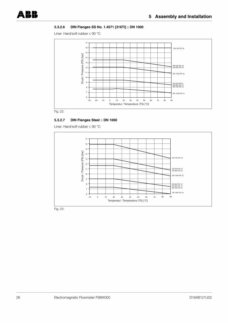
5.3.2.6 DIN Flanges SS No. 1.4571 [316Ti] ≤ DN 1000
Liner: Hard/soft rubber ≤ 90 °C
5.3.2.7 DIN Flanges Steel ≤ DN 1000
Liner: Hard/soft rubber ≤ 90 °C
Fig. 22:
Fig. 23:
6
7
8
9
10
11
12
13
14
15
16
17
DN 700 PN 16
DN 900 PN 16DN 800 PN 16
DN 1000 PN 16
DN 900 PN10DN 800 PN 10DN 700 PN 10
DN 1000 PN 10
Temperatur / Temperature (TS) [°C]
Dru
ck /
Pre
ssur
e (P
S)
[bar
]
-30 -20 -10 0 10 20 30 40 50 60 70 80 90
DN 700 PN 16
DN 900 PN 16DN 800 PN 16
DN 1000 PN 16
DN 900 PN 10DN 800 PN 10DN 700 PN 10
DN 1000 PN 10
Temperatur / Temperature (TS) [°C]
Dru
ck /
Pre
ssur
e (P
S)
[bar
]
6
7
8
9
10
11
12
13
14
15
16
17
-10 0 10 20 30 40 50 60 70 80 90
26 Electromagnetic Flowmeter FSM4000 D184B121U02
5 Assembly and Installation
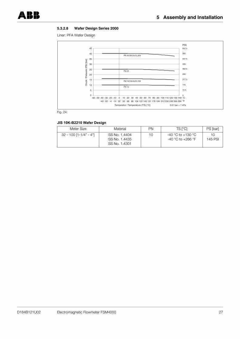
5.3.2.8 Wafer Design Series 2000
Liner: PFA Wafer Design
JIS 10K-B2210 Wafer Design
Fig. 24:
Meter Size Material PN TS [°C] PS [bar]
32 - 100 [1-1/4” - 4"] SS No. 1.4404SS No. 1.4435SS No. 1.4301
10 -40 °C to +130 °C-40 °C to +266 °F
10145 PSI
Temperatur / Temperature (TS) [°C]
Dru
ck /
Pre
ssur
e (P
S)
[bar
]
PN 40/300 lb/CL300
652.5
PSI
580
507.5
435
362.5
290
217.5
145
72.5
0
PN 25
PN 16/150 lb/CL150
PN 10
0
5
10
15
20
25
30
35
40
45
-30
-22-40
-40-50-60 -20
-4
-10
-14
0
32
10
50
20
68
30
86
40
104
50
122
60
140
70
151
80
176
90
194
100
212
110
230
120
248
130
266
140 °C
°F284
0.01 bar = 1 kPa
D184B121U02 Electromagnetic Flowmeter FSM4000 27
6 Electrical Connections
6 Electrical Connections
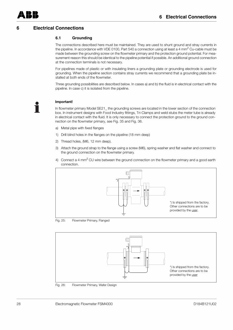
6.1 Grounding
The connections described here must be maintained. They are used to shunt ground and stray currents inthe pipeline. In accordance with VDE 0100, Part 540 a connection using at least a 4 mm2 Cu-cable must bemade between the grounding screw on the flowmeter primary and the protection ground potential. For mea-surement reason this should be identical to the pipeline potential if possible. An additional ground connectionat the connection terminals is not necessary.
For pipelines made of plastic or with insulating liners a grounding plate or grounding electrode is used forgrounding. When the pipeline section contains stray currents we recommend that a grounding plate be in-stalled at both ends of the flowmeter.
Three grounding possibilities are described below. In cases a) and b) the fluid is in electrical contact with thepipeline. In case c) it is isolated from the pipeline.
a) Metal pipe with fixed flanges
1) Drill blind holes in the flanges on the pipeline (18 mm deep)
2) Thread holes, (M6, 12 mm deep).
3) Attach the ground strap to the flange using a screw (M6), spring washer and flat washer and connect to the ground connection on the flowmeter primary.
4) Connect a 4 mm2 CU wire between the ground connection on the flowmeter primary and a good earth connection.
Important!
In flowmeter primary Model SE21_ the grounding screws are located in the lower section of the connectionbox. In instrument designs with Food Industry fittings, Tri-Clamps and weld stubs the meter tube is alreadyin electrical contact with the fluid. It is only necessary to connect the protection ground to the ground con-nection on the flowmeter primary, see Fig. 35 and Fig. 36.
Fig. 25: Flowmeter Primary, Flanged
Fig. 26: Flowmeter Primary, Wafer Design
*)
*) Is shipped from the factory. Other connections are to be provided by the user.
*)
*) Is shipped from the factory. Other connections are to be provided by the user
28 Electromagnetic Flowmeter FSM4000 D184B121U02
6 Electrical Connections
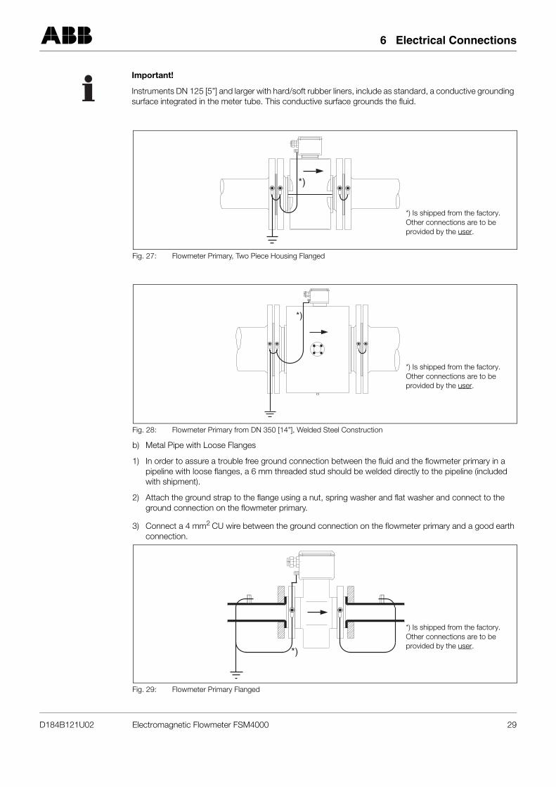
b) Metal Pipe with Loose Flanges
1) In order to assure a trouble free ground connection between the fluid and the flowmeter primary in a pipeline with loose flanges, a 6 mm threaded stud should be welded directly to the pipeline (included with shipment).
2) Attach the ground strap to the flange using a nut, spring washer and flat washer and connect to the ground connection on the flowmeter primary.
3) Connect a 4 mm2 CU wire between the ground connection on the flowmeter primary and a good earth connection.
Important!
Instruments DN 125 [5”] and larger with hard/soft rubber liners, include as standard, a conductive groundingsurface integrated in the meter tube. This conductive surface grounds the fluid.
Fig. 27: Flowmeter Primary, Two Piece Housing Flanged
Fig. 28: Flowmeter Primary from DN 350 [14”], Welded Steel Construction
Fig. 29: Flowmeter Primary Flanged
*)
*) Is shipped from the factory. Other connections are to be provided by the user.
*)
*) Is shipped from the factory. Other connections are to be provided by the user.
*)
*) Is shipped from the factory. Other connections are to be provided by the user.
D184B121U02 Electromagnetic Flowmeter FSM4000 29
6 Electrical Connections
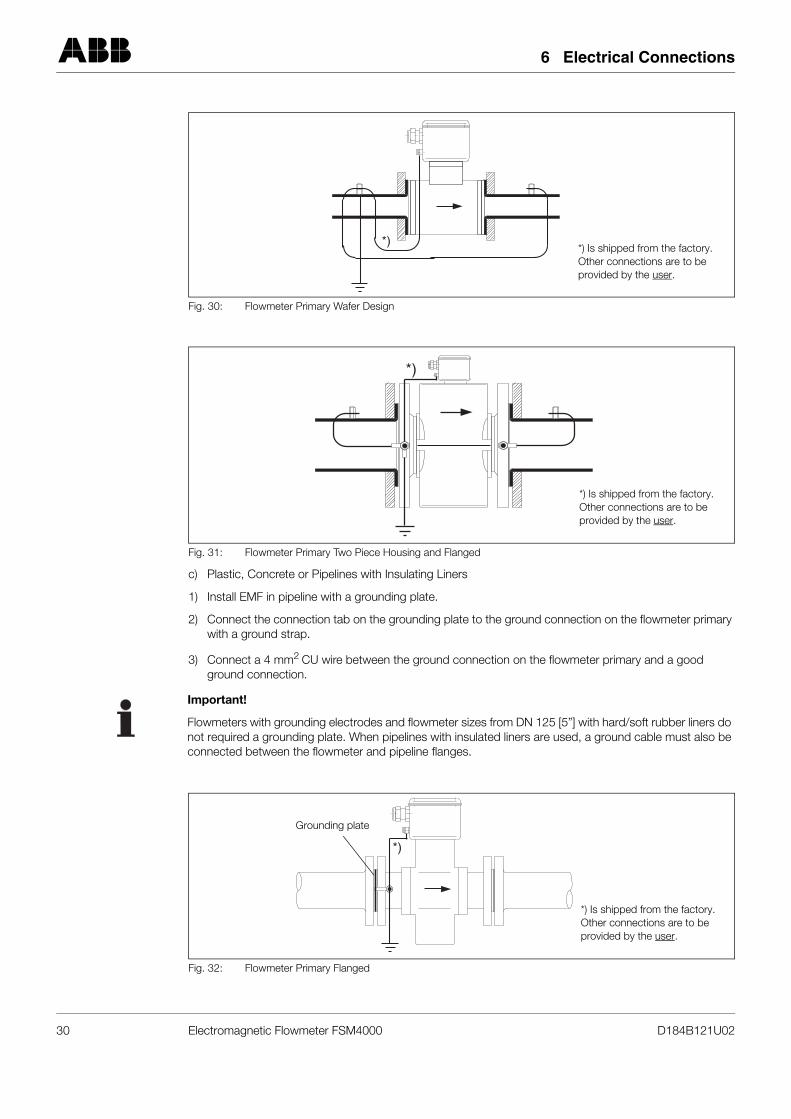
c) Plastic, Concrete or Pipelines with Insulating Liners
1) Install EMF in pipeline with a grounding plate.
2) Connect the connection tab on the grounding plate to the ground connection on the flowmeter primary with a ground strap.
3) Connect a 4 mm2 CU wire between the ground connection on the flowmeter primary and a good ground connection.
Fig. 30: Flowmeter Primary Wafer Design
Fig. 31: Flowmeter Primary Two Piece Housing and Flanged
*)*) Is shipped from the factory. Other connections are to be provided by the user.
*)
*) Is shipped from the factory. Other connections are to be provided by the user.
Important!
Flowmeters with grounding electrodes and flowmeter sizes from DN 125 [5”] with hard/soft rubber liners donot required a grounding plate. When pipelines with insulated liners are used, a ground cable must also beconnected between the flowmeter and pipeline flanges.
Fig. 32: Flowmeter Primary Flanged
*)
*) Is shipped from the factory. Other connections are to be provided by the user.
Grounding plate
30 Electromagnetic Flowmeter FSM4000 D184B121U02
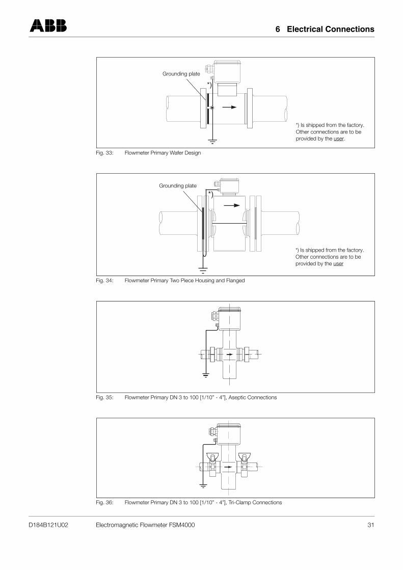
6 Electrical Connections
Fig. 33: Flowmeter Primary Wafer Design
Fig. 34: Flowmeter Primary Two Piece Housing and Flanged
Fig. 35: Flowmeter Primary DN 3 to 100 [1/10” - 4”], Aseptic Connections
Fig. 36: Flowmeter Primary DN 3 to 100 [1/10” - 4”], Tri-Clamp Connections
*)
*) Is shipped from the factory. Other connections are to be provided by the user.
Grounding plate
*)
*) Is shipped from the factory. Other connections are to be provided by the user
Grounding plate
D184B121U02 Electromagnetic Flowmeter FSM4000 31
6 Electrical Connections
6.1.1 Supply Power Connections
The supply power connections are made in accordance with the specifications on the Name Plate. High volt-age at terminals L (Phase) and N (Neutral), and or low voltage and terminals 1+, 2- and at the con-verter over a main fuse and switch.
The electromagnetic flowmeter primary is connected to the converter by a signal/reference voltage cable anda magnet coil supply cable. For detailed wiring information see the Operating Instruction for the converter.
6.1.2 Magnet Coil Supply Connections
The magnet coils are supplied directly from the converter over terminals M1, M3 using a shielded cable 2 x1.0 mm2. A 10 m long cable is included with the shipment unless a different length was ordered.
6.1.3 Power
The connection voltage and current specifications are listed on the Name Plate. The lead cross-section forthe supply power and the installed fuse size must be compatible (VDE 0100). The power consumption is S≤ 50 VA (flowmeter primary including the converter).
6.1.4 Signal Cable Connections
The signal cable conducts an AC signal of only a few millivolts and therefore should be routed along theshortest path. The cables should not be routed in the vicinity of large electrical machinery and switch gearequipment which could induce stray fields, pulses and voltages. The signal cable should not be fed throughbranch fittings or terminals strips.
The max. allowable signal cable length for designs without a preamplifier in 50 m. When a preamplifier isinstalled in the flowmeter primary for low conductivity applications the max. signal cable length is 200 m. Inthe cable, a shielded reference voltage cable runs parallel the signal leads so that only two cables are re-quired between the flowmeter primary and the converter. The construction of the signal cable includes a alu-minium-polyester-foil which surrounds the individually shielded signal cables and the shielded referencevoltage cable. The signal lead shields are “Driven Shields” for transmitting the signal voltage.
To shield against magnetic pickup an outer woven steel shield surrounds the entire cable which is connectedto terminal SE.
The signal/reference voltage cable is connected to the flowmeter primary and the converter in accordancewith the Interconnection Diagrams. If the actual flow direction does not agree with the flow direction arrowin the flowmeter primary, interchange the connections at 1 and 1S with those at 2 and 2S at the flowmeterprimary. For flowmeter primaries with preamplifiers, only interchange the connections at terminals 1 and 2 .
The common potential 3 is the same as the common potential of the flowmeter primary, which is connectedto earth per VDE 0100.
!Caution!
The signal cable connections vary dependent on the function. Observe the appropriate Interconnection Di-agram!
Important!
If plant conditions make it impossible to avoid proximity to electrical machinery or switch gear equipment, itis advisable to route the signal cable through a grounded metal conduit.
When a preamplifier is installed in a flowmeter primaries it is supplied by a DC voltage connected to terminalsU- and U+.
32 Electromagnetic Flowmeter FSM4000 D184B121U02
6 Electrical Connections
6.1.5 Interconnection Diagram
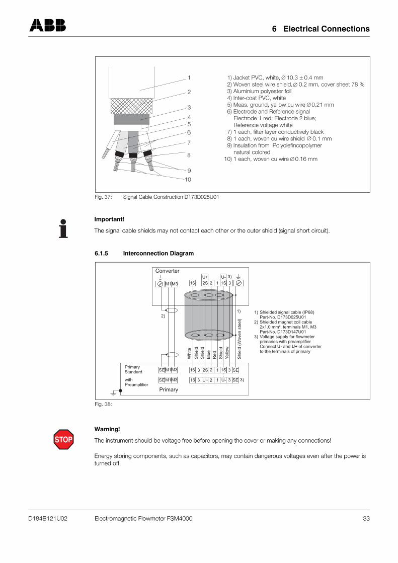
Fig. 37: Signal Cable Construction D173D025U01
1
2
3
456
7
8
9
10
1) Jacket PVC, white, 10.3 0.4 mm2) Woven steel wire shield, 0.2 mm, cover sheet 78 %3) Aluminium polyester foil4) Inter-coat PVC, white
6) Electrode and Reference signalElectrode 1 red; Electrode 2 blue;Reference voltage white
7) 1 each, filter layer conductively black8) 1 each, woven cu wire shield 0.1 mm9) Insulation from Polyolefincopolymer
natural colored10) 1 each, woven cu wire 0.16 mm
5) Meas. ground, yellow cu wire 0.21 mm
Important!
The signal cable shields may not contact each other or the outer shield (signal short circuit).
Fig. 38:
Converter
Primary
White
Blu
e
Red
Yellow
Shie
ld(W
oven
ste
el)
Shie
ld
Shie
ld
Shie
ld
Primary
Standard
with
Preamplifier
Shielded signal cable (IP68)
Part-No. D173D025U01
Shielded magnet coil cable
2x1.0 mm², terminals M1, M3
Part-No. D173D147U01
Voltage supply for flowmeter
primaries with preamplifier
Connect and of converter
to the terminals of primary
U- U+
1)
2)
3)
M1M3
1)
3)
2)
SE
SE
16
16
M1
M1
M3
M3
2S
U+
1S
U-
2
2
3
3
3
3
1
1
SE
SE
3)
16 2 1S 32S
U+ U-
1
STOPWarning!
The instrument should be voltage free before opening the cover or making any connections!
Energy storing components, such as capacitors, may contain dangerous voltages even after the power is turned off.
D184B121U02 Electromagnetic Flowmeter FSM4000 33
6 Electrical Connections
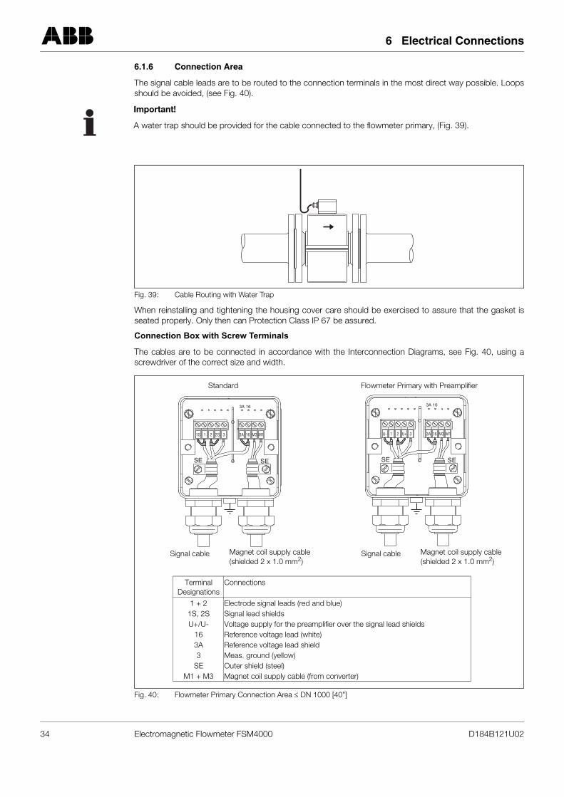
6.1.6 Connection Area
The signal cable leads are to be routed to the connection terminals in the most direct way possible. Loopsshould be avoided, (see Fig. 40).
When reinstalling and tightening the housing cover care should be exercised to assure that the gasket isseated properly. Only then can Protection Class IP 67 be assured.
Connection Box with Screw Terminals
The cables are to be connected in accordance with the Interconnection Diagrams, see Fig. 40, using ascrewdriver of the correct size and width.
Important!
A water trap should be provided for the cable connected to the flowmeter primary, (Fig. 39).
Fig. 39: Cable Routing with Water Trap
Fig. 40: Flowmeter Primary Connection Area ≤ DN 1000 [40”]
SE SE
3A
3A1S 2S1 2 3 16 M3 M1
16
SE SE
3A
3AU- U+1 2 3 16 M3 M1
16
Magnet coil supply cable(shielded 2 x 1.0 mm2)
Signal cable
Standard Flowmeter Primary with Preamplifier
Magnet coil supply cable(shielded 2 x 1.0 mm2)
Signal cable
Terminal Designations
Connections
1 + 21S, 2SU+/U-
163A3
SEM1 + M3
Electrode signal leads (red and blue)Signal lead shieldsVoltage supply for the preamplifier over the signal lead shieldsReference voltage lead (white)Reference voltage lead shieldMeas. ground (yellow)Outer shield (steel)Magnet coil supply cable (from converter)
34 Electromagnetic Flowmeter FSM4000 D184B121U02
7 Replaceable Parts, Flowmeter Primary
7 Replaceable Parts, Flowmeter Primary
If the liner, electrodes or magnet coils require repair the flowmeter primary must be returned to ABB Auto-mation Products Göttingen, Germany. Please see the information contained in the paragraph entitled “EUHazardous Material Directives” in Section Fig. 4.1.14 “Returns”.
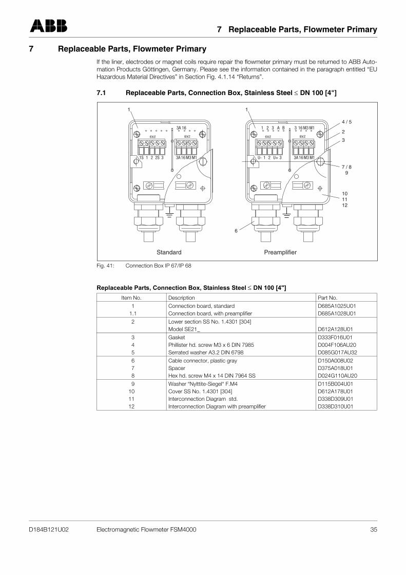
7.1 Replaceable Parts, Connection Box, Stainless Steel ≤ DN 100 [4"]
Replaceable Parts, Connection Box, Stainless Steel ≤ DN 100 [4"]
Fig. 41: Connection Box IP 67/IP 68
Item No. Description Part No.
11.1
Connection board, standardConnection board, with preamplifier
D685A1025U01D685A1028U01
2 Lower section SS No. 1.4301 [304]Model SE21_ D612A128U01
345
GasketPhillister hd. screw M3 x 6 DIN 7985Serrated washer A3.2 DIN 6798
D333F016U01D004F106AU20D085G017AU32
678
Cable connector, plastic graySpacerHex hd. screw M4 x 14 DIN 7964 SS
D150A008U02D375A018U01D024G110AU20
9101112
Washer “Nylttite-Siegel“ F.M4Cover SS No. 1.4301 [304]Interconnection Diagram std.Interconnection Diagram with preamplifier
D115B004U01D612A178U01D338D309U01D338D310U01
A B321 M133A 16 M316
2X92X9 2X82X8
M1M1 3A3A 1616 M3M3 33 U+2S 11 U�1S 22
1 1
4 / 5
2
6
Standard Preamplifier
3
101112
7 / 89
D184B121U02 Electromagnetic Flowmeter FSM4000 35
7 Replaceable Parts, Flowmeter Primary
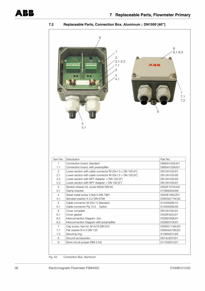
7.2 Replaceable Parts, Connection Box, Aluminum ≤ DN1000 [40”]
Fig. 42: Connection Box, Aluminum
Item No. Description Part No.
11.1
Connection board, standardConnection board, with preamplifier
D685A1025U01D685A1028U01
22.12.22.3
Lower section with cable connector M 20x1.5 ≤ DN 100 [4"]Lower section with cable connector M 20x1.5 > DN 100 [4"]Lower section with NPT-Adapter ≤ DN 100 [4"]Lower section with NPT-Adapter > DN 100 [4"]
D612A153U01D612A153U05D612A153U03D612A153U07
33.1
Slotted cheese hd. screw M3x8 DIN 84Clamp bracket
D002F107AU20D108A003U08
44.1
Sheet metal screw 2.9x6.5 DIN 7981 Serrated washer A 3.2 DIN 6798
D055E106CZ01D085G017AU32
55.1
Cable connector M 20x1.5 StandardCable connector Pg 13.5 Option
D150A008U15D150A008U02
66.16.26.3
Cover complete Cover gasketInterconnection Diagram std.Interconnection Diagram with preamplifier
D612A152U01D333F022U01D338D309U01D338D310U01
77.17.2
Cap screw, hex hd. M 4x18 DIN 912Flat washer B 4.3 DIN 125Securing ring
D009G113AU20D085A021BU20D106A001U25
8 Ground accessories D614L607U01
9 Short circuit jumper (RM 2.54) D172A001U01
9
1
22.1-2.31.1
3
44.1
55.1
77.17.2
8
66.1-6.3
36 Electromagnetic Flowmeter FSM4000 D184B121U02
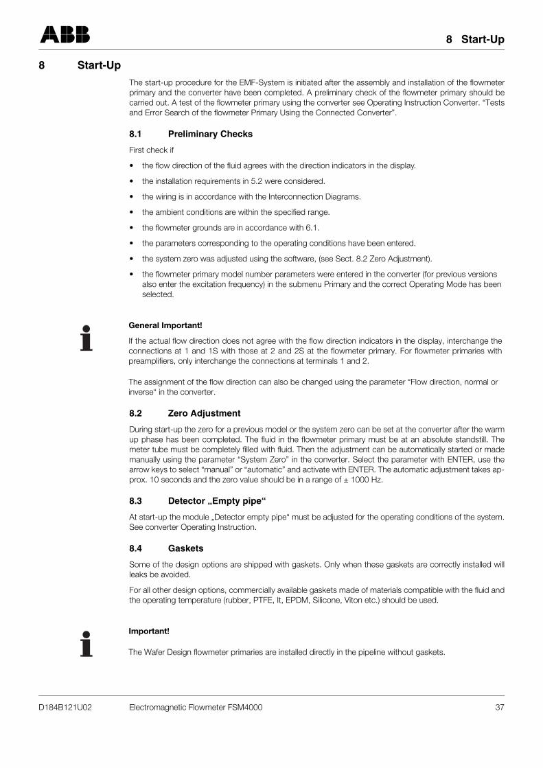
8 Start-Up
8 Start-Up
The start-up procedure for the EMF-System is initiated after the assembly and installation of the flowmeterprimary and the converter have been completed. A preliminary check of the flowmeter primary should becarried out. A test of the flowmeter primary using the converter see Operating Instruction Converter. “Testsand Error Search of the flowmeter Primary Using the Connected Converter”.
8.1 Preliminary Checks
First check if
• the flow direction of the fluid agrees with the direction indicators in the display.
• the installation requirements in 5.2 were considered.
• the wiring is in accordance with the Interconnection Diagrams.
• the ambient conditions are within the specified range.
• the flowmeter grounds are in accordance with 6.1.
• the parameters corresponding to the operating conditions have been entered.
• the system zero was adjusted using the software, (see Sect. 8.2 Zero Adjustment).
• the flowmeter primary model number parameters were entered in the converter (for previous versions also enter the excitation frequency) in the submenu Primary and the correct Operating Mode has been selected.
8.2 Zero Adjustment
During start-up the zero for a previous model or the system zero can be set at the converter after the warmup phase has been completed. The fluid in the flowmeter primary must be at an absolute standstill. Themeter tube must be completely filled with fluid. Then the adjustment can be automatically started or mademanually using the parameter “System Zero” in the converter. Select the parameter with ENTER, use thearrow keys to select “manual” or “automatic” and activate with ENTER. The automatic adjustment takes ap-prox. 10 seconds and the zero value should be in a range of ± 1000 Hz.
8.3 Detector „Empty pipe“
At start-up the module „Detector empty pipe“ must be adjusted for the operating conditions of the system.See converter Operating Instruction.
8.4 Gaskets
Some of the design options are shipped with gaskets. Only when these gaskets are correctly installed willleaks be avoided.
For all other design options, commercially available gaskets made of materials compatible with the fluid andthe operating temperature (rubber, PTFE, It, EPDM, Silicone, Viton etc.) should be used.
General Important!
If the actual flow direction does not agree with the flow direction indicators in the display, interchange theconnections at 1 and 1S with those at 2 and 2S at the flowmeter primary. For flowmeter primaries withpreamplifiers, only interchange the connections at terminals 1 and 2.
The assignment of the flow direction can also be changed using the parameter “Flow direction, normal or inverse“ in the converter.
Important!
The Wafer Design flowmeter primaries are installed directly in the pipeline without gaskets.
D184B121U02 Electromagnetic Flowmeter FSM4000 37
8 Start-Up
8.5 Maintenance
The flowmeter primary is essentially maintenance free. Annually a check should be conducted of the ambientconditions (air circulation, humidity), seal integrity of the process connections, cable connectors and coverscrews, functional reliability of the supply voltage, the lightning protection and the grounds.
The electrodes in the flowmeter primary must be cleaned when the flow indication display in the converterchanges even though the flow has not. For higher flowrate readings an insulating coating is the cause, forlower readings a conductive short circuiting coating is the cause.
General Important!
All repairs or maintenance tasks should be performed by qualified service personnel.
If the flowmeter primary is to be returned to ABB Automation Products Göttingen, Germany for repair,please see the information contained in the paragraph entitled “EU Hazardous Material Directives” in Section4.1.14 “Returns”!
38 Electromagnetic Flowmeter FSM4000 D184B121U02
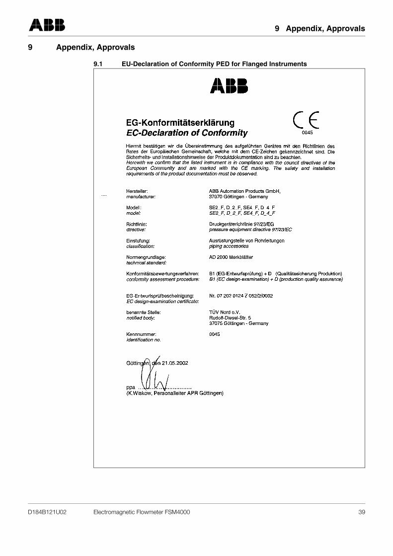
9 Appendix, Approvals
9 Appendix, Approvals
9.1 EU-Declaration of Conformity PED for Flanged Instruments
D184B121U02 Electromagnetic Flowmeter FSM4000 39
9 Appendix, Approvals
9.2 EU-Declaration of Conformity PED for Wafer Design Instruments and Instruments with Variable Process Connections
40 Electromagnetic Flowmeter FSM4000 D184B121U02
9 Appendix, Approvals
9.3 Instrument EMC-Directive 89/336/EWG and Low Voltage Directive 73/23/EEC
D184B121U02 Electromagnetic Flowmeter FSM4000 41


ABB has Sales & Customer Supportexpertise in over 100 countries worldwide.
www.abb.com
The Company’s policy is one of continuous productimprovement and the right is reserved to modify the
information contained herein without notice.
Printed in the Fed. Rep. of Germany (07.05)
© ABB 2005
ABB Ltd.Oldends Lane, StonehouseGloucestershire, GL 10 3TAUKPhone: +44(0)1453 826661Fax: +44(0)1453 829671
ABB Inc.125 E. County Line RoadWarminster, PA 18974USAPhone: +1 215 674 6000Fax: +1 215 674 7183
ABB Automation Products GmbHDransfelder Str. 237079 GöttingenGERMANYPhone: +49 551 905-534Fax: +49 551 905-555
D18
4B12
1U02
Rev
. 02