Embed Size (px)
Citation preview

Installation GuideIM/AP Issue 10
Insertion-Type Electromagnetic ProbeFlowmeter
AquaProbe 2

ABBEN ISO 9001:2000
Cert. No. Q 05907
EN 29001 (ISO 9001)
Lenno, Italy – Cert. No. 9/90A
Stonehouse, U.K.
����
Electrical Safety
This equipment complies with the requirements of CEI/IEC 61010-1:2001-2 'Safety Requirements for Electrical Equipmentfor Measurement, Control and Laboratory Use'. If the equipment is used in a manner NOT specified by the Company, theprotection provided by the equipment may be impaired.
Symbols
One or more of the following symbols may appear on the equipment labelling:
Warning – Refer to the manual for instructions Direct current supply only
Caution – Risk of electric shock Alternating current supply only
Protective earth (ground) terminal Both direct and alternating current supply
Earth (ground) terminal The equipment is protected through double insulation
The Company
We are an established world force in the design and manufacture of instrumentation forindustrial process control, flow measurement, gas and liquid analysis and environmentalapplications.
As a part of ABB, a world leader in process automation technology, we offer customersapplication expertise, service and support worldwide.
We are committed to teamwork, high quality manufacturing, advanced technology andunrivalled service and support.
The quality, accuracy and performance of the Company’s products result from over 100 yearsexperience, combined with a continuous program of innovative design and development toincorporate the latest technology.
The UKAS Calibration Laboratory No. 0255 is just one of the ten flow calibration plantsoperated by the Company and is indicative of our dedication to quality and accuracy.
Information in this manual is intended only to assist our customers in the efficient operation of our equipment. Use of thismanual for any other purpose is specifically prohibited and its contents are not to be reproduced in full or part without priorapproval of the Technical Publications Department.
Health and Safety
To ensure that our products are safe and without risk to health, the following points must be noted:
1. The relevant sections of these instructions must be read carefully before proceeding.2. Warning labels on containers and packages must be observed.3. Installation, operation, maintenance and servicing must only be carried out by suitably trained personnel and in accordance with
the information given.4. Normal safety precautions must be taken to avoid the possibility of an accident occurring when operating in conditions of high
pressure and/or temperature.5. Chemicals must be stored away from heat, protected from temperature extremes and powders kept dry. Normal safe handling
procedures must be used.6. When disposing of chemicals ensure that no two chemicals are mixed.
Safety advice concerning the use of the equipment described in this manual or any relevant hazard data sheets (where applicable) may be obtained from the Company address on the back cover, together with servicing and spares information.

Insertion-Type Electromagnetic Probe FlowmeterAquaProbe 2
IM/AP Issue 10 1
1 Introduction ...................................................................................................................................... 31.1 System Schematic ................................................................................................................... 3
2 Mechanical Installation .................................................................................................................... 42.1 Location – Environmental Conditions ....................................................................................... 4
2.1.1 AquaProbe .................................................................................................................... 42.1.2 Transmitter .................................................................................................................... 5
2.2 Location – Flow Conditions ...................................................................................................... 62.2.1 International Standard for Flow Measurement ................................................................ 62.2.2 Velocity Limitations ........................................................................................................ 7
2.3 Location – Mechanical ............................................................................................................. 92.3.1 AquaProbe .................................................................................................................... 92.3.2 Transmitter .................................................................................................................. 10
2.4 Safety .................................................................................................................................... 112.5 Installing the AquaProbe ........................................................................................................ 122.6 Setting the Insertion Depth .................................................................................................... 13
2.6.1 Centre Line Method for Pipe Diameters ≤1 m (≤40 in) .................................................. 132.6.2 Centre Line Method for Pipe Diameters >1 m ≤2 m (>40 in ≤80 in) .............................. 142.6.3 Mean Axial Velocity Method ......................................................................................... 15
2.7 AquaProbe Alignment ............................................................................................................ 16
3 Electrical Installation ..................................................................................................................... 173.1 Connections .......................................................................................................................... 17
3.1.1 Sensor Terminal Box Connections (Remote Versions only) .......................................... 173.1.2 Environmental Protection ............................................................................................. 183.1.3 Transmitter Connections ............................................................................................. 19
3.2 Input/Output Connections ..................................................................................................... 213.2.1 Frequency Outputs ...................................................................................................... 213.2.2 PLC Interface .............................................................................................................. 223.2.3 MIL Connector Input/Output Connections (Option) ...................................................... 233.2.4 Local Computer Connection ........................................................................................ 243.2.5 Remote Computer Connection (Option) ....................................................................... 253.2.6 Power Supply Connection Options .............................................................................. 263.2.7 Pressure Transducer (Optional) .................................................................................... 283.2.8 Environmental Protection (Option) ................................................................................ 29

Insertion-Type Electromagnetic Probe FlowmeterAquaProbe 2
2 IM/AP Issue 10
4 Setting Up .......................................................................................................................................304.1 Introduction ............................................................................................................................304.2 Centre Line Method ...............................................................................................................314.3 Mean Axial Velocity Method (1/8 Diameter) .............................................................................324.4 Partial Velocity Traverse .........................................................................................................324.5 AquaProbe Transmitter Setup ................................................................................................32
5 Start Up And Operation .................................................................................................................335.1 Fitting the Battery ...................................................................................................................335.2 Start-up .................................................................................................................................345.3 Display Activation ...................................................................................................................345.4 Replacing the Battery .............................................................................................................35
Appendix A 36A.1 Testing the Flow Profile for Symmetry ....................................................................................36
A.1.1 Partial Velocity Traverse ...............................................................................................36A.1.2 Single Entry Point Method ............................................................................................36A.1.3 Dual Entry Point Method ..............................................................................................37
Appendix B AquaMaster Block Diagram ............................................................................................ 38
Notes ..................................................................................................................................................39

Insertion-Type Electromagnetic Probe FlowmeterAquaProbe 2 1 Introduction
IM/AP Issue 10 3
1 IntroductionThe AquaProbe electromagnetic insertion flowmeter is designed for measurement of the velocity of water.
The flowmeter, available in four standard lengths, can be installed in any pipeline of internal diameter from200 mm (8 in) to 8000 mm (360 in), through a small tapping.
The AquaProbe is designed for use in survey applications such as leakage monitoring and network analysisand in permanent locations where cost or space limitations preclude the use of conventional closed pipemeters.
1.1 System Schematic
Note. Warranty
The AquaProbe sensor tip material is warranted for a period of 3 years as standard against material andmanufacturing defects. This warranty can be extended for a further 2 years upon request. TheAquaProbe shaft and mechanical components, along with the transmitter, have a standard 12 monthwarranty period.
Note. Care of the Equipment
The tip of the AquaProbe is a precision-built part of the equipment and must be handled withcare.
When the AquaProbe is not in use, fully retract the tip of the probe and replace the end-cap.
When removing/inserting the probe into the pipeline, ensure that the valve is fully open.
Damage to the probe effects the performance.
Physical damage to the probe invalidates the warranty.
Fig. 1.1 System Schematic
Or
Potted Connections
Sensor

Insertion-Type Electromagnetic Probe FlowmeterAquaProbe 2 2 Mechanical Installation
4 IM/AP Issue 10
2 Mechanical Installation
2.1 Location – Environmental Conditions
2.1.1 AquaProbe
Fig. 2.1 Environmental Requirements – AquaProbe
A – Within Temperature Limits
–20 °C (–4 °F)
Minimum
60 °C (140 °F)
Maximum
10 m
(30 ft)
C – Avoid Excessive Vibration
B – Within Environmental Rating
IP68 (NEMA 6)

Insertion-Type Electromagnetic Probe FlowmeterAquaProbe 2 2 Mechanical Installation
IM/AP Issue 10 5
2.1.2 Transmitter
Fig. 2.2 Environmental Requirements – AquaMaster & Explorer Transmitter
������������������
������������������
������������������
���������
–20 °C (–4 °F)
Minimum
60 °C (140 °F)
Maximum
A – Within Temperature Limits
B – Within Environmental Rating
C – Shade from Heat
1.5 m
(60 in)
Submerged – Up to 9 Months
Accrued TimeIP68 (NEMA 6) ENCLOSURE 6P

Insertion-Type Electromagnetic Probe FlowmeterAquaProbe 2 2 Mechanical Installation
6 IM/AP Issue 10
2.2 Location – Flow ConditionsThe probe may be installed in one of two positions in the pipe; either on the centre line or at the mean axialvelocity point (1/8 pipe diameter). It may also be traversed across the pipe to determine the velocity profile.
2.2.1 International Standard for Flow MeasurementISO 7145 '(BS 1042) Measurement of fluid flow in closed conduits 'Part 2 Velocity area methods' describesmethods of calculating volumetric flow from velocity measurements.
Section 2.2: 1982 'Method of measurement of velocity at one point of a conduit of circular cross section'describes the inference of volumetric flow from measurement of velocity at a single point. Severalconditions must be fulfilled to validate the method, which uses calculations based on empirical data.
Where the validating conditions can be met, the method described in Section 2.2 is the most practical. It ispossible to measure the velocity either on the centre line, which reduces sensitivity to positional errors, or atthe assumed point of mean flow velocity.
Table 2.1, page 7 is an extract from ISO 7145 (BS 1042): Section 2.2: 1982 and is reproduced with thepermission of BSI. Complete copies of the standard can be obtained by post from BSI Publications, LinfordWood, Milton Keynes, MK14 6LE.
Note. Ensure that the sensor is installed in the pipe with the flow direction arrow on the probe casematching the pipe flow.
Fig. 2.3 Flow Conditions
Note. Where the above ideal conditions cannot be achieved, the flow profile must be tested forsymmetry in order to obtain reliable flow results.
5 Diameters See Table 2.1, Page 7

Insertion-Type Electromagnetic Probe FlowmeterAquaProbe 2 2 Mechanical Installation
IM/AP Issue 10 7
2.2.2 Velocity LimitationsAll insertion probe devices are susceptible to the vortex shedding effect which can cause severe vibration ofthe probe, resulting in damage and/or measurement instability. Electromagnetic devices with no movingparts, such as AquaProbe, are less susceptible to this effect than mechanical devices.
The graphs below show the maximum permissible velocities, depending on the probe's location.
This information is provided as a guide only. Some installations may experience unwanted vibrationresonance which may further limit the maximum velocity at which the AquaProbe may be used.
Minimum upstream straight length*
Type of disturbance upstream from the measuring cross-section
For a measurement at the point of mean axial velocity
For a measurement on the axis of the conduit
90° elbow or a t-bend
Several 90° coplanar bends
Several 90° non- coplanar bends
Total angle convergent 18 to 36°
Total angle divergent 14 to 28°
Fully opened butterfly valve
Fully opened plug valve
50
50
80
30
55
45
30
25
25
50
10
25
25
15
* Expressed in multiples of the diameter of the conduit.
Downstream from the measurement cross-section, the straight length shall be at least equal to five duct diameters whatever the type of disturbance.
Table 2.1 Straight Pipe Lengths
Fig. 2.4 Maximum Permissible Velocity for Different Pipe Sizes
Pipe Size in Inches
Pipe Size in mmCentre Line Method
Max
imum
Vel
oci
ty in
ft/
s
Max
imum
Vel
oci
ty in
m/s
8 16 24 32 40 48 56 64 72 8020.0
17.0
13.0
10.0
7.0
3.0
00 200 400 600 800 1000 1200 1400 1600 1800 2000
6.0
5.0
4.0
3.0
2.0
1.0
0

Insertion-Type Electromagnetic Probe FlowmeterAquaProbe 2 2 Mechanical Installation
8 IM/AP Issue 10
Fig. 2.5 Maximum Permissible Velocity for Different Pipe Sizes
Fig. 2.6 Maximum Permissible Velocity for Different Insertion Lengths
Pipe Size in Inches
Pipe Size in mm
Mean Axial Velocity Method (1/8)
Max
imum
Vel
oci
ty in
ft/
s
Max
imum
Vel
oci
ty in
m/s
8 16 24 32 40 48 56 64 72 8020.0
17.0
13.0
10.0
7.0
3.0
00 200 400 600 800 1000 1200 1400 1600 1800 2000
6.0
5.0
4.0
3.0
2.0
1.0
0
Pipe Size in Inches
Pipe Size in mmTraversing
Max
imum
Vel
oci
ty in
ft/
s
Max
imum
Vel
oci
ty in
m/s
8 16 24 32 40 48 56 64 72 8020.0
17.0
13.0
10.0
7.0
3.0
00 200 400 600 800 1000 1200 1400 1600 1800 2000
6.0
5.0
4.0
3.0
2.0
1.0
0

Insertion-Type Electromagnetic Probe FlowmeterAquaProbe 2 2 Mechanical Installation
IM/AP Issue 10 9
2.3 Location – Mechanical
2.3.1 AquaProbe
Note. Pipeline recommended to be metal for electrical screening.
Dimensions in mm (in)
Fig. 2.7 Mechanical Requirements – AquaProbe
320 (12.5)
900, 1100, 1300 or 1600
(36, 44, 52 or 63)
1 in BSP1.5 in BSP1 in NPT
On Centre Line
On Cen
tre Li
ne
A – Clearance Dimensions
B – Orientation

Insertion-Type Electromagnetic Probe FlowmeterAquaProbe 2 2 Mechanical Installation
10 IM/AP Issue 10
2.3.2 Transmitter
Dimensions in mm (in)
Fig. 2.8 Clearance Dimensions – Transmitter
Dimensions in mm (in)
Fig. 2.9 Clearance Dimensions – Transmitter
���������
Installation and Wiring Access 300 (11.8) min.
450 (17.7) Preferred
170 (6.7)
170(6.7) 140
(5.5)
Allowance for Cable Bend130 (5.1) [Standard]200 (7.9) [Armoured]
Allowance for Cable Bend130 (5.1) [Standard]200 (7.9) [Armoured]
Transmitter Mounting Plate
Ø6.0 (0.24)
Ø12.0 (0.47)
Ø6.0 (0.24)
170(6.7)
150(5.9)
146 (5.7)125 (4.9)
Transmitter Mounting Plate Details
���������
105 (4.1)
136(5.4)
168(6.6)
177 (7.0)
115 (4.5)50 (2.0)
21(0.8)
Ø13 (0.5)
Ø6.5 (0.3)

Insertion-Type Electromagnetic Probe FlowmeterAquaProbe 2 2 Mechanical Installation
IM/AP Issue 10 11
2.4 Safety
Warning. The Aquaprobe is provided with a safety mechanism (see Fig. 2.10A) that must be attachedto its securing collar as shown in Fig. 2.10B. This prevents rapid outward movement by the probe if nut1 is released.
Note. To ensure maximum safety, the positioning collar MUST be tightened in place using a 4 mmhexagon key
Fig. 2.10 Safety Mechanism
�
See Warning
A – Unsecured B – Secured

Insertion-Type Electromagnetic Probe FlowmeterAquaProbe 2 2 Mechanical Installation
12 IM/AP Issue 10
2.5 Installing the AquaProbe
Warning. When inserting or removing the AquaProbe suitable restraining equipment must be used toprevent the probe being forced out under pressure. Ensure that the valve is fully open.
Dimensions in mm (in)
Fig. 2.11 Insertion Bore Clearance
Fig. 2.12 Installing the AquaProbe
25 (1) MinimumClearance
�
�
�
�
�
Referring to Fig. 2.12:
1 Tighten the nut (hand tight only).
2 Remove the cap.
3 Apply PTFE tape.
4 Insert the probe into the valve.
5 Tighten firmly.

Insertion-Type Electromagnetic Probe FlowmeterAquaProbe 2 2 Mechanical Installation
IM/AP Issue 10 13
2.6 Setting the Insertion Depth
2.6.1 Centre Line Method for Pipe Diameters ≤1 m (≤40 in)
Warning. When inserting or removing the AquaProbe suitable restraining equipment must be used toprevent the probe being forced out under pressure. Ensure that the valve is fully open.
Note. Safety restraint omitted for clarity.
Fig. 2.13 Setting the insertion Depth – Centre Line Method for Pipe Diameters 1 m (40 in)
�
�
�
�
�
�
�
�
See Note
Referring to Fig. 2.13:
1 Determine the internal diameter (D).
2 Open the valve fully.
3 Slacken the nut.
4 Insert the probe into the valve.
5 Slide the positioning collar down to the nut and lock in place.
6 Retract the probe fully.
7 Unlock, slide the positioning collar down and lock at the distance:
8 Insert the probe to position collar depth.
9 Tighten to 40 Nm (30 ft lbf).
D2---- 30 mm (1.181 in)+

Insertion-Type Electromagnetic Probe FlowmeterAquaProbe 2 2 Mechanical Installation
14 IM/AP Issue 10
2.6.2 Centre Line Method for Pipe Diameters >1 m ≤2 m (>40 in ≤80 in)
Warning. When inserting or removing the AquaProbe suitable restraining equipment must be used toprevent the probe being forced out under pressure. Ensure that the valve is fully open.
Note. Safety restraint omitted for clarity.
Fig. 2.14 Setting the Insertion Depth – Centre Line Method for Pipe Diameters >1 m 2 m (>40 in 80 in)
��
�
�
�
��
�
�
�
See Note
Referring to Fig. 2.14:
1 Determine the internal diameter (D).
2 Measure to the top of the valve plate (VP).
3 Slacken the nut.
4 Lower the probe to touch the valve plate.
5 Slide the positioning collar down to the nut and lock in place.
6 Retract the probe fully.
7 Unlock, slide the positioning collar down and lock at the distance:
8 Open the valve fully.
9 Insert probe to position the collar depth.
0 Tighten to 40 Nm (30 ft lbf).
D2---- VP 30 mm (1.181 in) pipe thickness.+ + +

Insertion-Type Electromagnetic Probe FlowmeterAquaProbe 2 2 Mechanical Installation
IM/AP Issue 10 15
2.6.3 Mean Axial Velocity Method
Warning. When inserting or removing the AquaProbe suitable restraining equipment must be used toprevent the probe being forced out under pressure. Ensure that the valve is fully open.
Note. Safety restraint omitted for clarity.
Fig. 2.15 Setting the Insertion Depth – Mean Axial Velocity Method
�
�
��
�
�
�
���
�
�
See Note
Referring to Fig. 2.15:
1 Determine the internal diameter (D).
2 Measure to the top of the valve plate (VP).
3 Slacken the nut.
4 Lower the probe to touch the valve plate.
5 Slide the positioning collar down to the nut and lock in place.
6 Retract the probe fully.
7 Unlock, slide the positioning collar down and lock at the distance:
8 Open the valve fully.
9 Insert probe to position the collar depth.
0 Tighten to 40 Nm (30 ft lbf).
D8---- VP 30 mm (1.181 in) pipe thickness.+ + +
Insertion-Type Electromagnetic Probe FlowmeterAquaProbe 2 2 Mechanical Installation
16 IM/AP Issue 10
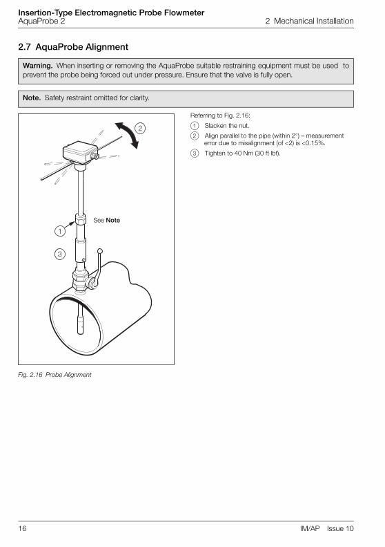
2.7 AquaProbe Alignment
Warning. When inserting or removing the AquaProbe suitable restraining equipment must be used toprevent the probe being forced out under pressure. Ensure that the valve is fully open.
Note. Safety restraint omitted for clarity.
Fig. 2.16 Probe Alignment
�
�
�
�
�
�
See Note
Referring to Fig. 2.16:
1 Slacken the nut.
2 Align parallel to the pipe (within 2°) – measurement error due to misalignment (of <2) is <0.15%.
3 Tighten to 40 Nm (30 ft lbf).

Insertion-Type Electromagnetic Probe FlowmeterAquaProbe 2 3 Electrical Installation
IM/AP Issue 10 17
3 Electrical Installation
3.1 Connections
3.1.1 Sensor Terminal Box Connections (Remote Versions only)
Caution. (Remote versions)
Make connections only as shown.
Remove foil screens
Twist the three screen wires together and sleeve them.
Twist cable pairs together
Maintain Environmental Protection at all times.
Conduit connections must provide cable entry sealing.
Fig. 3.1 Sensor Terminal Box Connections (Remote Version)
Caution. With Belden Cable 8777, ensure that the black wires are not interchanged, and remain withthe associated twisted pair.
CABLE
ABB Belden 8777
Violet White
Blue Black
Green Sleeved Ground
Yellow Red
Orange Black
Red Green
Brown Black
Maximum Cable Lengths
250 m 80 m

Insertion-Type Electromagnetic Probe FlowmeterAquaProbe 2 3 Electrical Installation
18 IM/AP Issue 10
3.1.2 Environmental Protection
Fig. 3.2 Potting the Terminal Box
Warning.
Potting materials are toxic – use suitable safety precautions.
Read the manufacturers instructions carefully before preparing the potting material.
The remote sensor terminal box connections must be potted immediately on completion toprevent the ingress of moisture.
Check all connections before potting – see Section 3, Page 17.
Do not overfill or allow the potting material to come into contact with 'O' rings or grooves.
Do not let potting material enter conduit, if used.

Insertion-Type Electromagnetic Probe FlowmeterAquaProbe 2 3 Electrical Installation
IM/AP Issue 10 19
3.1.3 Transmitter Connections
Caution.
To ensure cable glands seal, use cable of diameter 7 to 11 mm (0.28 to 0.43 in) only.
Ensure cable glands are tightened after wiring.
Ensure that 'O' ring seals and mating surfaces are clean, to maintain environmental rating.
Fig. 3.3 Transmitter Connection Terminal Access
Fig. 3.4 Transmitter Connection (Glands/Conduit Entry)
�
��
�
Slacken Captive Screws
Remove Cover

Insertion-Type Electromagnetic Probe FlowmeterAquaProbe 2 3 Electrical Installation
20 IM/AP Issue 10
Caution. (Remote versions)
Make connections only as shown.
Remove foil screens
Twist the three screen wires together and sleeve them.
Twist cable pairs together
Maintain Environmental Protection at all times.
Conduit connections must provide cable entry sealing.
Fig. 3.5 Sensor Cable Connections (Gland/Conduit, Remote version)
Fig. 3.6 Sensor Cable Connections (Connector, Remote version)
Note. This arrangement is an option.
� �
CABLE
Belden 8777 ABB
1 Black 1 Brown
2 Green 2 Red
3 Black 3 Orange
4 Red 4 Yellow
5 Sleeved Ground 5 Sleeved Ground
6 Black 6 Blue
7 White 7 Violet
AquaMaster Transmitter
� �
AquaMaster Transmitter

Insertion-Type Electromagnetic Probe FlowmeterAquaProbe 2 3 Electrical Installation
IM/AP Issue 10 21
3.2 Input/Output Connections
3.2.1 Frequency Outputs
Caution.
Refer to SPECIFICATION SHEET for Input/Output ratings.
Inductive loads must be suppressed or clamped to limit voltage swings
Capacitive loads must be inrush current limited.
Fig. 3.7 Frequency Output Connections
Note. Outputs 1, 2 & 3 are not polarity sensitive. The common connection for these outputs isdesignated 'COM'.
� � � � � �
� � � � � �
� � � � � �
AquaMaster Transmitter
AquaMaster TransmitterCounter/Totalisers
Counter/Totalisers
Electromechanical Connections
Telemetry, Electronic Counters etc.
DC supply
and/or
and/or
Forward Flow
Forward Flow
Reverse Flow
Reverse Flow
CO
MO
/P1
O/P
2
CO
MO
/P1
O/P
2

Insertion-Type Electromagnetic Probe FlowmeterAquaProbe 2 3 Electrical Installation
22 IM/AP Issue 10
3.2.2 PLC Interface
Fig. 3.8 Frequency and Alarm Output Connections
Note. Outputs 1, 2 & 3 are not polarity sensitive. The common connection for these outputs isdesignated 'COM'. Output 3 is an option and may not function on some models.
AquaMaster Transmitter
PLC
CO
MO
/P1
O/P
2O
/P3
Common
Input 1
Input 2
Input 3

Insertion-Type Electromagnetic Probe FlowmeterAquaProbe 2 3 Electrical Installation
IM/AP Issue 10 23
3.2.3 MIL Connector Input/Output Connections (Option)
Fig. 3.9 MIL Connector Connections
Pin Name Function Color (Output cable)
A – Reserved
B – Reserved
C – Reserved
D O/P 1 Forward Pulses Orange
E O/P 3 Output 3 White/Orange
F O/P 2 Reverse Pulses or Direction Blue
G O/P Com Common Drain Wire
H – Reserved
J I/P Gnd Input Common White
K I/P+ Contact Input Violet
L RXD Receive data (serial input connection) Turquoise
M TXD Transmit data (serial output connection) Brown
N RTS Request to send Red/Black
P CTS Clear to send Yellow/Red
R – Reserved
S – Reserved
T RI Ring Indicator Yellow
U – Reserved
V Serial GND Comms Ground Green
Table 3.1 MIL Connector Connections
AquaMaster Transmitter Part No. MVBX 99147

Insertion-Type Electromagnetic Probe FlowmeterAquaProbe 2 3 Electrical Installation
24 IM/AP Issue 10
3.2.4 Local Computer Connection
Fig. 3.10 Local Computer Connections – AquaMaster
Fig. 3.11 Local Computer Connections – Explorer
ABB LimitedPart No.WEBC2000
Connected to 9-pin Serial Data Socket on PDA or PC via
'Laplink' Lead
9-pin Male(for Link Lead to Psion)
9-pin Female(Direct to PC)

Insertion-Type Electromagnetic Probe FlowmeterAquaProbe 2 3 Electrical Installation
IM/AP Issue 10 25
3.2.5 Remote Computer Connection (Option)
Fig. 3.12 RS232 Connections
AquaMaster Terminal RS232 9-PIN PC Connector 25-PIN PC Connector
TXD TXD 3 2
RXD RXD 2 3
RTS RTS 7 4
CTS CTS 8 5
RI RI 9 22
GND GND 5 7
Table 3.2 RS232 Connections
AquaMaster Transmitter
GN
DRI
CTS
RTS
RXD
TXD
Radio Modem (Radio Pad), Computer or similar
Modem
Insertion-Type Electromagnetic Probe FlowmeterAquaProbe 2 3 Electrical Installation
26 IM/AP Issue 10
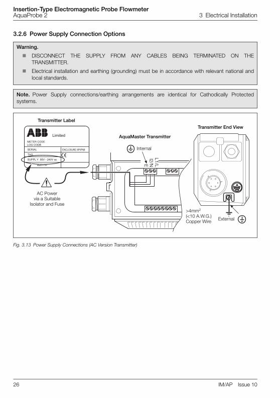
3.2.6 Power Supply Connection Options
Warning.
DISCONNECT THE SUPPLY FROM ANY CABLES BEING TERMINATED ON THETRANSMITTER.
Electrical installation and earthing (grounding) must be in accordance with relevant national andlocal standards.
Note. Power Supply connections/earthing arrangements are identical for Cathodically Protectedsystems.
Fig. 3.13 Power Supply Connections (AC Version Transmitter)
�������������
�����
���
����������
���� �����������
�������
���� ���� !�"�#$%!��&
AquaMaster Transmitter
Transmitter End ViewTransmitter Label
AC Powervia a Suitable
Isolator and Fuse
Internal
L1/Ll2/NE
>4mm2
(<10 A.W.G.)Copper Wire External

Insertion-Type Electromagnetic Probe FlowmeterAquaProbe 2 3 Electrical Installation
IM/AP Issue 10 27
Fig. 3.14 Power Supply Connections (DC Version Transmitter)
�������������
�����
���
����������
���� �����������
�������
���� �
AquaMaster Transmitter
Transmitter End ViewTransmitter Label
DC Supply
Internal
+–E>4mm2
(<10 A.W.G.)Copper Wire
External

Insertion-Type Electromagnetic Probe FlowmeterAquaProbe 2 3 Electrical Installation
28 IM/AP Issue 10
3.2.7 Pressure Transducer (Optional)Optional pressure transducer cables are available for a range of pressures and cable lengths.
Caution. Ensure that only the pressure transducer supplied with the transmitter is used.
Use of other pressure transducers requires alteration of the pressure span and zero factors in thetransmitter – see Quick Reference Programming guide.
Fig. 3.15 AquaMaster Transmitter fitted with Optional Pressure Transducer Connector
Fig. 3.16 Explorer Transmitter fitted with Optional Pressure Transducer Connector
Pressure TransducerConnector

Insertion-Type Electromagnetic Probe FlowmeterAquaProbe 2 3 Electrical Installation
IM/AP Issue 10 29
3.2.8 Environmental Protection (Option)
Warning.
Potting materials are toxic – use suitable safety precautions.
Read the manufacturers instructions carefully before preparing the potting material.
Fig. 3.17 Potting the Transmitter
Caution.
For increased protection against accidental water ingress, for example by poor gland tightening,pot the termination area.
Check all connections and operations before potting – see Section 3, Page 17.
Do not overfill or allow the potting material to come into contact with 'O' rings or grooves.
Do not let potting material enter conduit, if used.

Insertion-Type Electromagnetic Probe FlowmeterAquaProbe 2 4 Setting Up
30 IM/AP Issue 10
4 Setting Up
4.1 IntroductionThe basic equation for volume measurement using AquaProbe is:
Q = A Fi FP V
Where: Q = flow rate,
Fi = insertion factor
Fp = profile factor
V = velocity
A = area
The pipe diameter, profile factor and insertion factor must be determined as detailed in see Section 5.2,Page 34 to 5.3, as applicable.
Note. Due to software configuration, all calculations are in metric units. Therefore if using an imperialpipe, the diameter MUST be converted into millimeters (1 in = 25.4 mm) i.e. a 36 in pipe = 914 mm

Insertion-Type Electromagnetic Probe FlowmeterAquaProbe 2 4 Setting Up
IM/AP Issue 10 31
4.2 Centre Line Method
1. Determine the internal diameter D of the pipe, in millimeters, by the most accurate method available.
2. Determine the profile factor Fp from Fig.4.1.
3. Calculate the insertion factor
Example – for a pipe of internal diameter 593 mm (23.35 in):
Fp = 0.861 (derived from Fig. 4.1)
Fi = 1.021
Fig. 4.1 Profile Factor vs Velocity for Pipe Sizes 200 to 2000 mm (8 in to 80 in)
Fi1
1 38 πD( )⁄( )–-------------------------------------=
Fi1
1 38 π593( )⁄( )–-------------------------------------------=
Pipe Bore in Inches
Pipe Bore in mm
Pro
file
Fac
tor
(Fp
)
8 16 24 32 40 48 56 64 72 80
200 400 600 800 1000 1200 1400 1600 1800 2000
0.875
0.870
0.865
0.860
0.855
0.850

Insertion-Type Electromagnetic Probe FlowmeterAquaProbe 2 4 Setting Up
32 IM/AP Issue 10
4.3 Mean Axial Velocity Method (1/8 Diameter)
1. Determine the internal diameter D of the pipe, in millimeters, by the most accurate method available.
2. A profile factor Fp of 1 must be used.
3. Calculate the insertion factor
Example – for a pipe of internal diameter 593 mm (23.35 in):
Fp = 1
Fi = 1.074
4.4 Partial Velocity TraverseRefer to Appendix A.1.1, page 36 for the procedure.
4.5 AquaProbe Transmitter SetupThe AquaProbe Transmitter can be set up to display point velocity, mean velocity or flow rate, as required.For full programming details refer to the AquaProbe Quick Reference Guide.
Fi 1 12.09D
--------------- 1.3042D
------------------+ +=
Fi 1 12.09593
--------------- 1.3042593
------------------+ +=

Insertion-Type Electromagnetic Probe FlowmeterAquaProbe 2 5 Start Up And Operation
IM/AP Issue 10 33
5 Start Up And Operation
5.1 Fitting the BatteryIf the AquaMaster has been supplied with one or two batteries, but not connected, then proceed asfollows:
1. Remove the top cover of the transmitter – see Section 3.1.3, Page 19.
2. Invert the cover.
3. Slide out the connector from behind the battery retaining clamp.
4. Connect the battery or batteries to the wire connector(s) inside the top of the transmitter unit; lefthand battery to left hand connector and right hand battery to right hand connector.
5. Ensure that the end of the battery with the connection wires is pushed up against the inside end ofthe top cover.
6. Push the connection centrally behind the battery retaining clamp to secure the battery.
7. Fit the top cover to the transmitter and ensure the screws are tightened fully.
Warning.
The lithium battery used in this device may present a risk of fire or chemical burn if mistreated. Donot recharge, disassemble, heat above 100°C or incinerate.
Replace battery with ABB Limited Part No. WABC2001 only. Use of another battery may presenta risk of fire or explosion.
Dispose of used battery promptly. Keep away from children.
Dispose of used batteries in accordance with your local regulations.
Where possible, recycle used batteries.
Contact your local environmental authority for further information regarding disposal or recyclingschemes for used batteries.
Note.
If fitting a battery on an external powered (AC or DC) unit, ensure the unit is powered during thisoperation.
Each battery must be connected to the cable from the same side of the termination area as thebattery position in the lid.

Insertion-Type Electromagnetic Probe FlowmeterAquaProbe 2 5 Start Up And Operation
34 IM/AP Issue 10
5.2 Start-upIf the AquaMaster is received with a protective plastic film over the display window, remove this film beforecommencing normal operation.
When the power is connected or the plastic film is removed, the AquaMaster performs a self test operation,and indicates a successful completion with 'EE Pass' displayed.
If the display shows 'EE Fail 1', remove all power, check the sensor wiring and apply power.
If the display shows 'EE Fail 2 or 3', contact ABB.
5.3 Display ActivationFor normal operation, activate the light sensitive display by first covering the display area totally. Onremoving the covering, the display activates and cycles through the programmed set of displaymeasurements.
With external power applied, the display is permanently activated.
To alter the displayed set of measurements, or instrument setup, see the Quick Reference ProgrammingGuide.
Fig. 5.1 Location of Controls
Note. For the use of local or remote serial communication, and configuration, see the Quick ReferenceProgramming Guide.
� �����
�� ��������� � � � �����
������ �����������������
Pictorial DisplaysWarning annunciators
Left Battery Warning
DateForward Flow TotalReverse Flow TotalNet Flow Total
Upper Display
TimeFlow Velocity Pressure
Lower Display
Sensor Fault
Empty Pipe condition
Mains Failure
Right Battery Warning

Insertion-Type Electromagnetic Probe FlowmeterAquaProbe 2 5 Start Up And Operation
IM/AP Issue 10 35
5.4 Replacing the Battery
The flashing icon indicates the battery currently in use.
Proceed as follows:
1. Remove the top cover of the transmitter – see Section 3.1.3, Page 19.
2. Invert the cover.
3. Slide out the connector from behind the battery retaining clamp and pull the connector apart.
4. Remove the battery.
5. Fit a new battery (ABB Part No. WABC2001) ensuring that the end of the battery with the connectionwires is pushed up against the inside end of the top cover.
6. Connect the battery connector to the connector previously removed.
7. Push the connection centrally behind the battery retaining clamp to secure the battery.
8. Fit the top cover to the transmitter and ensure the screws are tightened fully.
Caution. If replacing the battery on an external powered (AC or DC) unit, ensure it is powered duringthis operation. For dual battery units, replace only the battery above the indicated battery legend.
Note. Each battery must be connected to the cable from the same side of the termination area as thebattery position in the lid.
Normal Operation
If both batteries are good, no battery alarm is indicated.
Replace Battery
When a battery alarm is shown, replace the cell on the side indicated. (In this example, the Right Battery).
Replace both batteries
If both batteries require replacement, it is important to first change the cell indicated by the steady icon.
��
����� � ����������
��
����� � ����������
��
����� � ����������

Insertion-Type Electromagnetic Probe FlowmeterAquaProbe 2 Appendix A
36 IM/AP Issue 10
Appendix A
A.1 Testing the Flow Profile for SymmetryIf there is any doubt as to the symmetry of the flow profile (see Section 2.2, Page 6), a Partial VelocityTraverse should be carried out. This procedure involves comparing the value of velocity at two points atequal distances from the centre line.
It is normal to compare the flow velocities at insertion depths of 1/8 and 7/8 of the pipe diameter as thesepoints are always on the 'knee' of the profile.
A.1.1 Partial Velocity TraverseDetermine the internal diameter D of the pipe, in millimeters, by the most accurate method available. If theAquaProbe insertion length is greater than the internal diameter of the pipe, proceed with the Single EntryPoint Method detailed in Section A.1.2. If the AquaProbe insertion length is less than the internal diameterof the pipe, proceed with the Dual Entry Point Method detailed in Section A.1.3.
A.1.2 Single Entry Point Method
1. Insert the probe to a depth of 1/8 the pipe diameter – see Fig. 2.15.
2. Calculate the insertion factor
3. Refer to the AquaProbe Transmitter Configuration Manual and enter a Blockage Factor (BL) of valueequal to Fi.
4. Record the flow velocity reading.
5. Insert the probe to a depth of 7/8 the pipe diameter.
6. Calculate the insertion factor.
7. Refer to the AquaProbe Transmitter Configuration Manual and enter a Blockage Factor (BL) of valueequal to Fi.
8. Record the flow velocity reading.
9. Calculate the ratio of the two values recorded.
If the ratio is between 0.95 and 1.05 the flow profile is acceptable and the procedure detailed in Section4.2, Page 31 can be used. If outside this ratio the AquaProbe should be resited for optimum accuracy.
Note. Due to software configuration, all calculations are in metric units. Therefore if using animperial pipe, the diameter MUST be converted into millimeters (1 in = 25.4 mm) i.e. a 36 in pipe= 914 mm.
Fi 1 12.09D
--------------- 1.3042D
------------------+ +=
Fi 1 12.09D
--------------- 1.3042
D------------------+ +=

Insertion-Type Electromagnetic Probe FlowmeterAquaProbe 2 Appendix A
IM/AP Issue 10 37
A.1.3 Dual Entry Point MethodRefer to Section 2.5 and fit a second mounting boss directly opposite the one already fitted.
1. Insert the probe to a depth of 1/8 the pipe diameter through the original mounting boss.
2. Calculate the insertion factor.
3. Refer to the AquaProbe Transmitter Configuration Manual and enter a Blockage Factor (BL) of valueequal to Fi.
4. Record the flow velocity reading.
5. Insert the probe to a depth of 1/8 the pipe diameter through the second mounting boss.
6. Record the flow velocity reading.
7. Calculate the ratio of the two values recorded
If the ratio is between 0.95 and 1.05 the flow profile is acceptable and the procedure detailed in Section4.2, Page 31 can be used. If outside this ratio the AquaProbe should be resited for optimum accuracy.
Note. Due to software configuration, all calculations are in metric units. Therefore if using an imperialpipe, the diameter MUST be converted into millimeters (1 in = 25.4 mm) i.e. a 36 in pipe = 914 mm.
Fi 1 12.09D
--------------- 1.3042D
------------------+ +=

Insertion-Type Electromagnetic Probe FlowmeterAquaProbe 2 Appendix B AquaMaster Block Diagram
38 IM/AP Issue 10
Appendix B AquaMaster Block Diagram
� � � � � ��
� � � � � ��
Opt
iona
l Pow
erS
uppl
y
Mai
n R
S23
2C
omm
unic
atio
nP
ort
Con
tact
Inpu
t
Pul
se/A
larm
Circ
uits
Com
mon
Dis
play
Loca
l Con
figur
atio
n A
dapt
or
Par
t No.
WE
BC
2000
Pro
cess
orM
easu
rem
ent
Sys
tem

Insertion-Type Electromagnetic Probe FlowmeterAquaProbe 2 Notes
IM/AP Issue 10 39
Notes

Insertion-Type Electromagnetic Probe FlowmeterAquaProbe 2 Notes
40 IM/AP Issue 10

PRODUCTS & CUSTOMER SUPPORTProducts
Automation Systems• for the following industries:
– Chemical & Pharmaceutical– Food & Beverage– Manufacturing– Metals and Minerals– Oil, Gas & Petrochemical– Pulp and Paper
Drives and Motors• AC and DC Drives, AC and DC Machines, AC
Motors to 1kV• Drive Systems• Force Measurement• Servo Drives
Controllers & Recorders• Single and Multi-loop Controllers• Circular Chart and Strip Chart Recorders• Paperless Recorders• Process Indicators
Flexible Automation• Industrial Robots and Robot Systems
Flow Measurement• Electromagnetic Flowmeters• Mass Flowmeters• Turbine Flowmeters• Wedge Flow Elements
Marine Systems & Turbochargers• Electrical Systems• Marine Equipment• Offshore Retrofit and Refurbishment
Process Analytics• Process Gas Analysis• Systems Integration
Transmitters• Pressure• Temperature• Level• Interface Modules
Valves, Actuators and Positioners• Control Valves• Actuators• Positioners
Water, Gas & Industrial Analytics Instrumentation
• pH, Conductivity and Dissolved Oxygen Transmitters and Sensors
• Ammonia, Nitrate, Phosphate, Silica, Sodium, Chloride, Fluoride, Dissolved Oxygen and Hydrazine Analyzers
• Zirconia Oxygen Analyzers, Katharometers, Hydrogen Purity and Purge-gas Monitors, Thermal Conductivity
Customer Support
We provide a comprehensive after sales service via aWorldwide Service Organization. Contact one of thefollowing offices for details on your nearest Service andRepair Centre.
United KingdomABB LimitedTel: +44 (0)1453 826661Fax: +44 (0)1453 829671
United States of AmericaABB Inc.Tel: +1 215 674 6000Fax: +1 215 674 7183
Client WarrantyPrior to installation, the equipment referred to in thismanual must be stored in a clean, dry environment, inaccordance with the Company's publishedspecification.
Periodic checks must be made on the equipment'scondition. In the event of a failure under warranty, thefollowing documentation must be provided assubstantiation:
1. A listing evidencing process operation and alarm logs at time of failure.
2. Copies of all storage, installation, operating and maintenance records relating to the alleged faulty unit.

IM/A
PIs
sue
10
ABB has Sales & Customer Support expertisein over 100 countries worldwide
www.abb.com
The Company’s policy is one of continuous product improvement and the right is reserved to modify the
information contained herein without notice.
Printed in UK (04.10)
© ABB 2010
ABB LimitedOldends Lane, StonehouseGloucestershireGL10 3TAUKTel: +44 (0)1453 826661Fax: +44 (0)1453 829671
ABB Inc.125 E. County Line RoadWarminsterPA 18974USATel:+1 215 674 6000Fax:+1 215 674 7183