Embed Size (px)
Citation preview
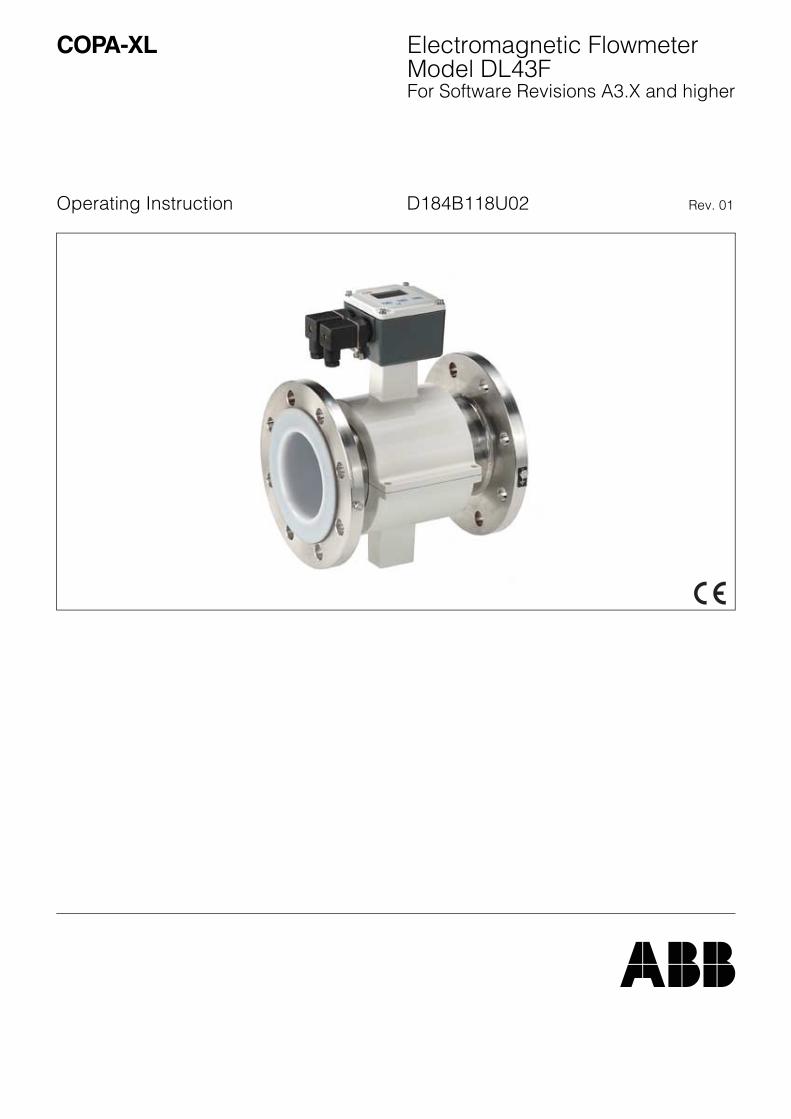
Electromagnetic FlowmeterModel DL43FFor Software Revisions A3.X and higher
COPA-XL
Operating Instruction D184B118U02 Rev. 01
Manufacturer
2 COPA-XL D184B118U02
Electromagnetic Flowmeter COPA-XL
Operating Instruction
PArt No. D184B118U02
Issue Date: 11.01Revision: 01
ManufacturerABB Automation Products GmbHDransfelder Str. 2
D-37079 Göttingen, Germany
Telephone: +49 (0) 55 19 05- 0Telefax: +49 (0) 55 19 05- 777
© Copyright 2001 by ABB Automation Products GmbHRevision reserved
This Operating Instruction is copyright protected. Translation, reproduction and distribution in any form - including editing or abstracts - and in particular, duplicating, photocopying, electronic distribution or storing in data processing installations without the express consent of the copyright holder is strictly forbidden and may be lead to civil and criminal proceedings.
D184B118U02 COPA-XL 3
1. Safety Information - - - - - - - - - - - - - - - - - - - - - - - - - - - - - - - - - - - - - - - - - - - - - - - - - - - - - - - - - - - - - - - - - - - - - - 51.1. Regulated Usage - - - - - - - - - - - - - - - - - - - - - - - - - - - - - - - - - - - - - - - - - - - - - - - - - - - - - - - - - - - - - - - - - - - - - - - - 51.2. Safety Markings and Symbols - - - - - - - - - - - - - - - - - - - - - - - - - - - - - - - - - - - - - - - - - - - - - - - - - - - - - - - - - - - - - - - 51.3. Installation, Start-Up, Operation and Maintenance Requirements - - - - - - - - - - - - - - - - - - - - - - - - - - - - - - - - - - - - - - 51.4. Safe Operation- - - - - - - - - - - - - - - - - - - - - - - - - - - - - - - - - - - - - - - - - - - - - - - - - - - - - - - - - - - - - - - - - - - - - - - - - - 61.5. Returns - - - - - - - - - - - - - - - - - - - - - - - - - - - - - - - - - - - - - - - - - - - - - - - - - - - - - - - - - - - - - - - - - - - - - - - - - - - - - - - 62. Technical Description- - - - - - - - - - - - - - - - - - - - - - - - - - - - - - - - - - - - - - - - - - - - - - - - - - - - - - - - - - - - - - - - - - - - 72.1. Functional Description - - - - - - - - - - - - - - - - - - - - - - - - - - - - - - - - - - - - - - - - - - - - - - - - - - - - - - - - - - - - - - - - - - - - 72.2. Operating Principle- - - - - - - - - - - - - - - - - - - - - - - - - - - - - - - - - - - - - - - - - - - - - - - - - - - - - - - - - - - - - - - - - - - - - - - 72.3. Construction - - - - - - - - - - - - - - - - - - - - - - - - - - - - - - - - - - - - - - - - - - - - - - - - - - - - - - - - - - - - - - - - - - - - - - - - - - - 73. Assembly and Installation - - - - - - - - - - - - - - - - - - - - - - - - - - - - - - - - - - - - - - - - - - - - - - - - - - - - - - - - - - - - - - - - 83.1. Inspection - - - - - - - - - - - - - - - - - - - - - - - - - - - - - - - - - - - - - - - - - - - - - - - - - - - - - - - - - - - - - - - - - - - - - - - - - - - - - 83.2. Installation Requirements, Flowmeter Primary - - - - - - - - - - - - - - - - - - - - - - - - - - - - - - - - - - - - - - - - - - - - - - - - - - - 83.2.1 Installing the Flowmeter Primary - - - - - - - - - - - - - - - - - - - - - - - - - - - - - - - - - - - - - - - - - - - - - - - - - - - - - - - - - - - - 113.2.2 Installations in Larger Size Pipelines - - - - - - - - - - - - - - - - - - - - - - - - - - - - - - - - - - - - - - - - - - - - - - - - - - - - - - - - - 123.2.3 Flowmeter Sizes, Pressure Ratings, Flow Ranges - - - - - - - - - - - - - - - - - - - - - - - - - - - - - - - - - - - - - - - - - - - - - - - 134. Programming the Converter - - - - - - - - - - - - - - - - - - - - - - - - - - - - - - - - - - - - - - - - - - - - - - - - - - - - - - - - - - - - - - 144.1. Overview of the Converter Factory Settings - - - - - - - - - - - - - - - - - - - - - - - - - - - - - - - - - - - - - - - - - - - - - - - - - - - - 145. Data Entry in „Condensed Form“ - - - - - - - - - - - - - - - - - - - - - - - - - - - - - - - - - - - - - - - - - - - - - - - - - - - - - - - - - - 156. Data Entry - - - - - - - - - - - - - - - - - - - - - - - - - - - - - - - - - - - - - - - - - - - - - - - - - - - - - - - - - - - - - - - - - - - - - - - - - - - 167. Circuit Boards - - - - - - - - - - - - - - - - - - - - - - - - - - - - - - - - - - - - - - - - - - - - - - - - - - - - - - - - - - - - - - - - - - - - - - - - 207.1. Fuse Locations on the Converter Circuit Board - - - - - - - - - - - - - - - - - - - - - - - - - - - - - - - - - - - - - - - - - - - - - - - - - - 208. Ordering Information - - - - - - - - - - - - - - - - - - - - - - - - - - - - - - - - - - - - - - - - - - - - - - - - - - - - - - - - - - - - - - - - - - - 219. Error Messages - - - - - - - - - - - - - - - - - - - - - - - - - - - - - - - - - - - - - - - - - - - - - - - - - - - - - - - - - - - - - - - - - - - - - - - 2210. Accuracy - - - - - - - - - - - - - - - - - - - - - - - - - - - - - - - - - - - - - - - - - - - - - - - - - - - - - - - - - - - - - - - - - - - - - - - - - - - - 2311. Safety Relevant Portion of the Instruction Bulletin - - - - - - - - - - - - - - - - - - - - - - - - - - - - - - - - - - - - - - - - - - - - - 2411.1. Grounding the Flowmeter Primary - - - - - - - - - - - - - - - - - - - - - - - - - - - - - - - - - - - - - - - - - - - - - - - - - - - - - - - - - - - 2411.2. Grounding Instruments with Hard Rubber Liners - - - - - - - - - - - - - - - - - - - - - - - - - - - - - - - - - - - - - - - - - - - - - - - - - 2612. Electrical Connections - - - - - - - - - - - - - - - - - - - - - - - - - - - - - - - - - - - - - - - - - - - - - - - - - - - - - - - - - - - - - - - - - - 2712.1. Interconnection Diagram - - - - - - - - - - - - - - - - - - - - - - - - - - - - - - - - - - - - - - - - - - - - - - - - - - - - - - - - - - - - - - - - - - 2712.2. Signal Outputs and Supply Power - - - - - - - - - - - - - - - - - - - - - - - - - - - - - - - - - - - - - - - - - - - - - - - - - - - - - - - - - - - 2813. Start-Up - - - - - - - - - - - - - - - - - - - - - - - - - - - - - - - - - - - - - - - - - - - - - - - - - - - - - - - - - - - - - - - - - - - - - - - - - - - - - 2913.1. Preliminary Checks of the Flowmeter Measurement System - - - - - - - - - - - - - - - - - - - - - - - - - - - - - - - - - - - - - - - - 2913.1.1 Checking the Flowmeter Primary COPA-XL - - - - - - - - - - - - - - - - - - - - - - - - - - - - - - - - - - - - - - - - - - - - - - - - - - - - 2913.2. System Zero Check/Adjustment- - - - - - - - - - - - - - - - - - - - - - - - - - - - - - - - - - - - - - - - - - - - - - - - - - - - - - - - - - - - - 2913.3. Maintenance / Repair - - - - - - - - - - - - - - - - - - - - - - - - - - - - - - - - - - - - - - - - - - - - - - - - - - - - - - - - - - - - - - - - - - - - 3013.4. Rotating the Display - - - - - - - - - - - - - - - - - - - - - - - - - - - - - - - - - - - - - - - - - - - - - - - - - - - - - - - - - - - - - - - - - - - - - 3013.5. Replaceable Parts, Flowmeter Primary- - - - - - - - - - - - - - - - - - - - - - - - - - - - - - - - - - - - - - - - - - - - - - - - - - - - - - - - 3014. Converter Specifications - - - - - - - - - - - - - - - - - - - - - - - - - - - - - - - - - - - - - - - - - - - - - - - - - - - - - - - - - - - - - - - - 31
4 COPA-XL D184B118U02
1 Safety Information
1 Safety Information
1.1 Regulated Usage
The operating, maintenance and installation requirements in this Instruction Bulletin must be followed.
Any damages resulting from improper or non-specified usage are not the responsibility of the manufacturer.
1.2 Safety Markings and Symbols
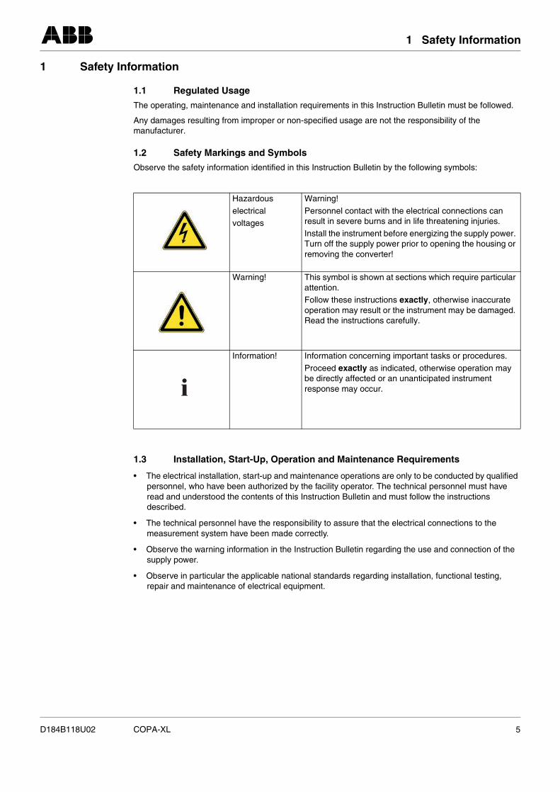
Observe the safety information identified in this Instruction Bulletin by the following symbols:
1.3 Installation, Start-Up, Operation and Maintenance Requirements
• The electrical installation, start-up and maintenance operations are only to be conducted by qualified personnel, who have been authorized by the facility operator. The technical personnel must have read and understood the contents of this Instruction Bulletin and must follow the instructions described.
• The technical personnel have the responsibility to assure that the electrical connections to the measurement system have been made correctly.
• Observe the warning information in the Instruction Bulletin regarding the use and connection of the supply power.
• Observe in particular the applicable national standards regarding installation, functional testing, repair and maintenance of electrical equipment.
Hazardous
electricalvoltages
Warning!
Personnel contact with the electrical connections can result in severe burns and in life threatening injuries.
Install the instrument before energizing the supply power. Turn off the supply power prior to opening the housing or removing the converter!
Warning! This symbol is shown at sections which require particular attention.Follow these instructions exactly, otherwise inaccurate operation may result or the instrument may be damaged. Read the instructions carefully.
Information! Information concerning important tasks or procedures.
Proceed exactly as indicated, otherwise operation may be directly affected or an unanticipated instrument response may occur.
D184B118U02 COPA-XL 5
1 Safety Information
1.4 Safe Operation
• This instrument has not been approved for installation in explosion hazardous locations.The instrument may only be installed in areas outside of the Ex-Zone and has been designed for Protection Class IP 65.
• The Electromagnetic Flowmeter is manufactured to the latest state of the art design and safety standards. The instrument was tested for compliance with the safety requirements at the factory and shipped in proper operating condition.
• This Instruction Bulletin contains information concerning start-up and testing and in addition includes the specifications for this instrument design. The manufacturer reserves the right to make revisions to the software and hardware resulting in technical improvements. Information about updates and possible new expanded features may be obtained from the factory in Göttingen, Germany or from your local ABB-Sales Bureau.
1.5 Returns
If it is necessary to return an instrument to the ABB factory in Göttingen, Germany for repair or recalibration, use the original or other suitable protective packing material. Please include the reason for the return.
6 COPA-XL D184B118U02
1 Technical Description
1 Technical Description
1.1 Functional Description
The Electromagnetic Flowmeters (EMF) from ABB are the ideal flow measurement instruments for liquids, slurries and sludges which have a specific minimum electrical conductivity. The flowmeters measure accurately, create no pressure drop and include no moving parts or components which extendinto the flow stream.
The ABB EMFs have been proven over decades and are the preferred flowmeters in the chemical, pharmaceutical and cosmetic industries, municipal water and waste treatment facilities, food industry and paper industry.
1.2 Operating Principle
The operation of the electromagnetic flowmeter is based on Faraday’s Laws of Induction which statesthat a voltage is generated in a conductor as it moves through a magnetic field.
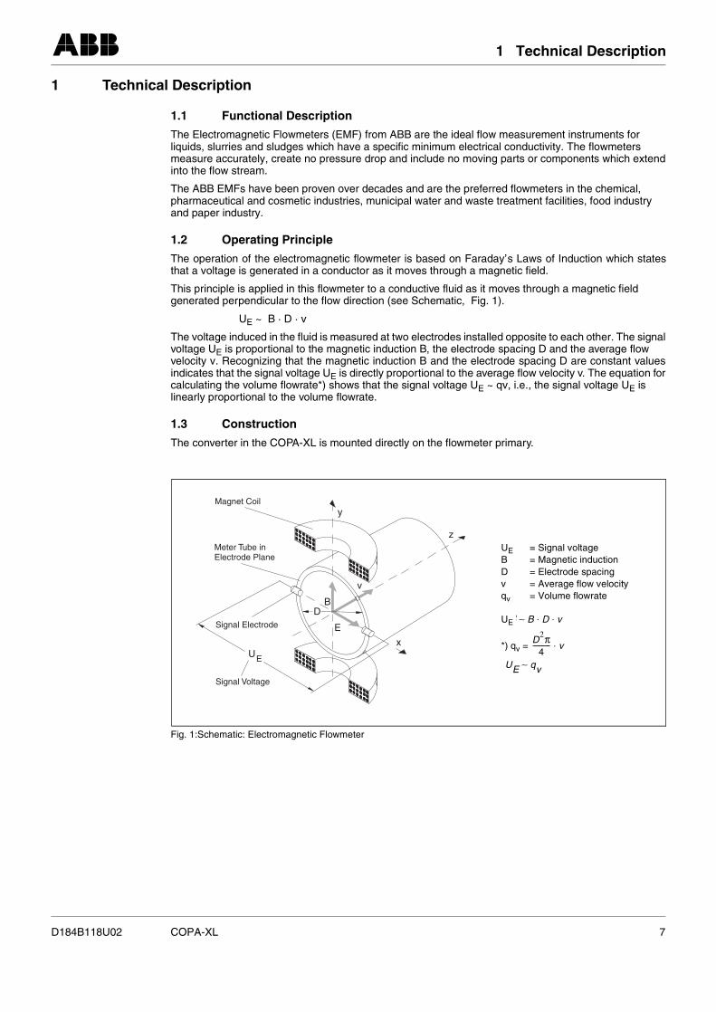
This principle is applied in this flowmeter to a conductive fluid as it moves through a magnetic field generated perpendicular to the flow direction (see Schematic, Fig. 1).
UE ~ B · D · v
The voltage induced in the fluid is measured at two electrodes installed opposite to each other. The signalvoltage UE is proportional to the magnetic induction B, the electrode spacing D and the average flow velocity v. Recognizing that the magnetic induction B and the electrode spacing D are constant valuesindicates that the signal voltage UE is directly proportional to the average flow velocity v. The equation forcalculating the volume flowrate*) shows that the signal voltage UE ~ qv, i.e., the signal voltage UE is linearly proportional to the volume flowrate.
1.3 Construction
The converter in the COPA-XL is mounted directly on the flowmeter primary.
Fig. 1:Schematic: Electromagnetic Flowmeter
UE
y
z
x
BD
E
v
Magnet Coil
Meter Tube inElectrode Plane
Signal Electrode
Signal Voltage
UE = Signal voltageB = Magnetic inductionD = Electrode spacingv = Average flow velocityqv = Volume flowrate
UE
*) qv =
B B∼ D v⋅ ⋅
D2π4
---------- v⋅
UE qv∼
D184B118U02 COPA-XL 7
2 Assembly and Installation
2 Assembly and Installation
2.1 Inspection
Before installing the flowmeter primary, check for mechanical damage due to possible improper handlingduring shipment. All claims for damage are to be made promptly to the shipper prior to installing themeter.
2.2 Installation Requirements, Flowmeter Primary
The flowmeter primary should not be installed in close proximity to strong electromagnetic fields.
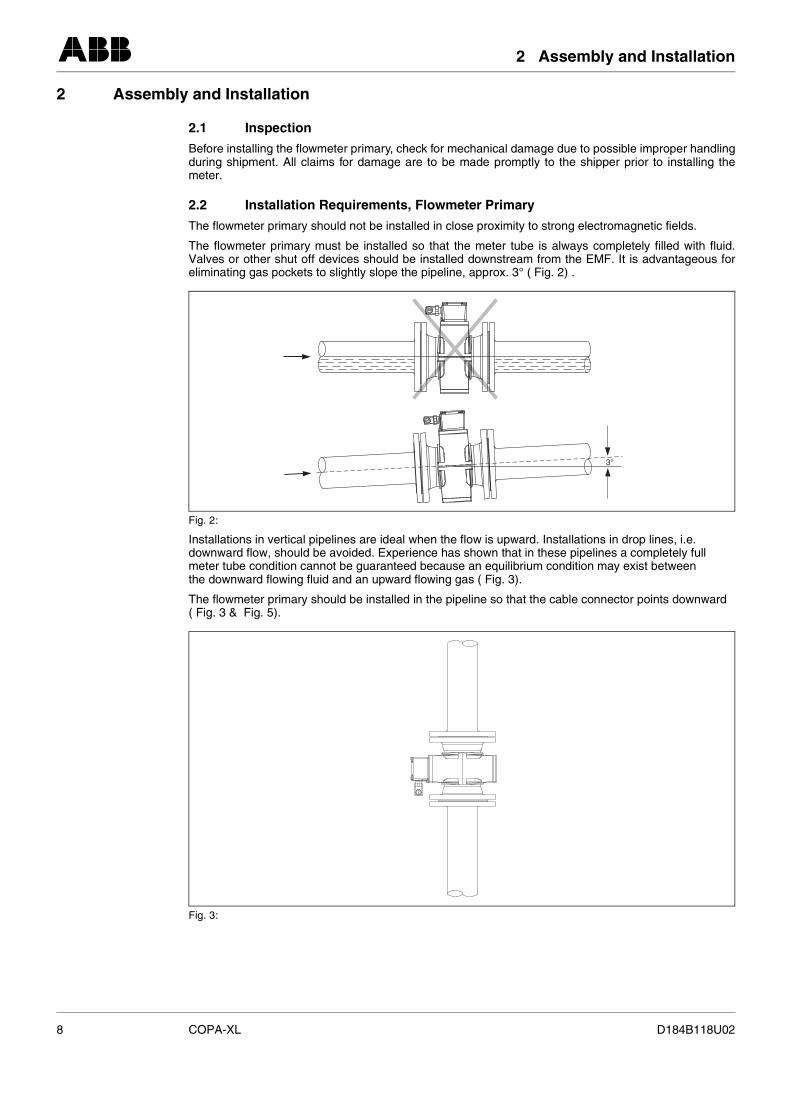
The flowmeter primary must be installed so that the meter tube is always completely filled with fluid.Valves or other shut off devices should be installed downstream from the EMF. It is advantageous foreliminating gas pockets to slightly slope the pipeline, approx. 3° ( Fig. 2) .
Installations in vertical pipelines are ideal when the flow is upward. Installations in drop lines, i.e. downward flow, should be avoided. Experience has shown that in these pipelines a completely full meter tube condition cannot be guaranteed because an equilibrium condition may exist between the downward flowing fluid and an upward flowing gas ( Fig. 3).
The flowmeter primary should be installed in the pipeline so that the cable connector points downward ( Fig. 3 & Fig. 5).
Fig. 2:
Fig. 3:
3°
8 COPA-XL D184B118U02
2 Assembly and Installation
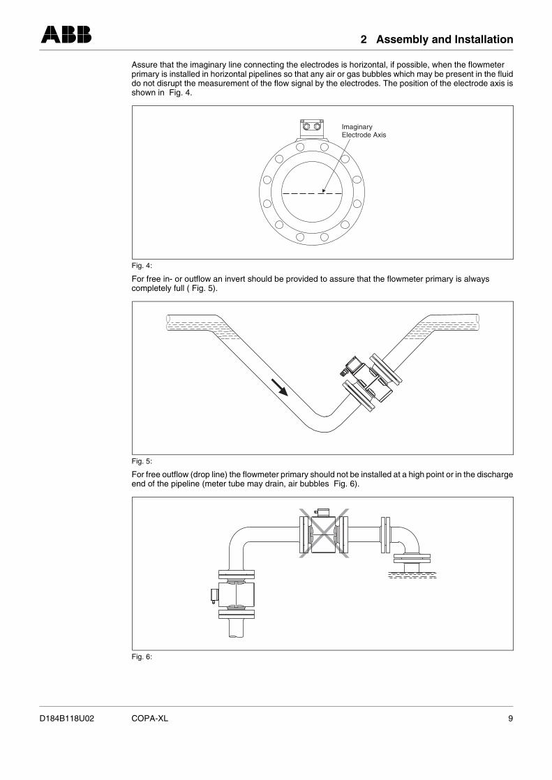
Assure that the imaginary line connecting the electrodes is horizontal, if possible, when the flowmeter primary is installed in horizontal pipelines so that any air or gas bubbles which may be present in the fluiddo not disrupt the measurement of the flow signal by the electrodes. The position of the electrode axis isshown in Fig. 4.
For free in- or outflow an invert should be provided to assure that the flowmeter primary is always completely full ( Fig. 5).
For free outflow (drop line) the flowmeter primary should not be installed at a high point or in the dischargeend of the pipeline (meter tube may drain, air bubbles Fig. 6).
Fig. 4:
Fig. 5:
Fig. 6:
ImaginaryElectrode Axis
D184B118U02 COPA-XL 9
2 Assembly and Installation
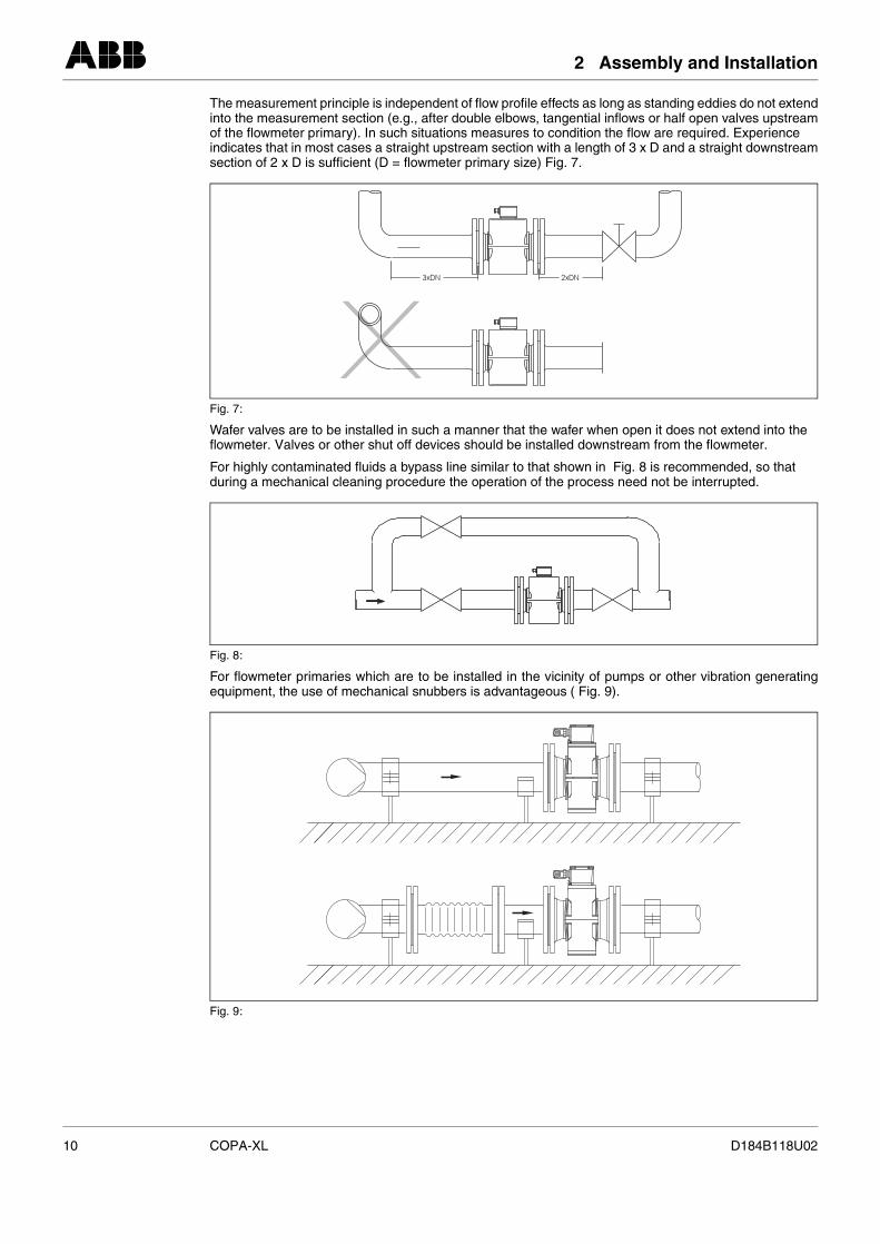
The measurement principle is independent of flow profile effects as long as standing eddies do not extendinto the measurement section (e.g., after double elbows, tangential inflows or half open valves upstreamof the flowmeter primary). In such situations measures to condition the flow are required. Experience indicates that in most cases a straight upstream section with a length of 3 x D and a straight downstreamsection of 2 x D is sufficient (D = flowmeter primary size) Fig. 7.
Wafer valves are to be installed in such a manner that the wafer when open it does not extend into the flowmeter. Valves or other shut off devices should be installed downstream from the flowmeter.
For highly contaminated fluids a bypass line similar to that shown in Fig. 8 is recommended, so that during a mechanical cleaning procedure the operation of the process need not be interrupted.
For flowmeter primaries which are to be installed in the vicinity of pumps or other vibration generatingequipment, the use of mechanical snubbers is advantageous ( Fig. 9).
Fig. 7:
Fig. 8:
Fig. 9:
10 COPA-XL D184B118U02
2 Assembly and Installation
2.2.1 Installing the Flowmeter Primary
The electromagnetic flowmeter can be installed at any arbitrary location in the pipeline as long as the installation requirements (see 2.2) are satisfied.
When selecting the installation site, consideration should be given to assure that moisture cannot enterinto the electrical connections or converter areas. Make certain to carefully seat the gaskets and securethe covers after installation and start-up have been completed.
WarningGraphite should not be used to lubricate the flange or process connection gaskets because, under certain circumstances, an electrically conductive coating may form on the inside surface of the meter tubeaffecting operation.
Gasket Surfaces on the Mating FlangesIn every installation parallel mating flange surfaces should be provided and gaskets made from materialssuitable for the fluid and the temperature are to be used. Only then can leaks be avoided. The flange gaskets for the flowmeter primary must be installed concentrically to achieve optimum measurement results.
Protection PlatesThe protection plates for the flowmeter primaries are installed to prevent damage to the liner during shipment. Remove the protection plates only when ready to install the meter in the pipeline. Be carefulnot to cut or otherwise damage the liner in order to avoid leaks.
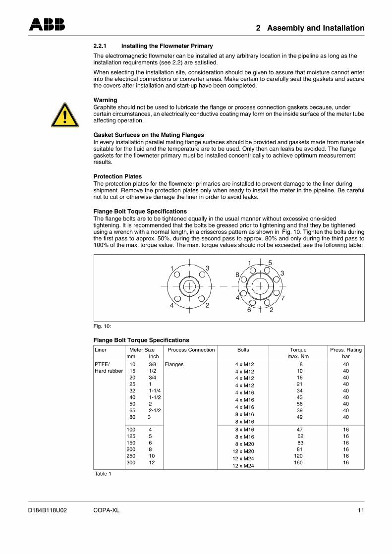
Flange Bolt Toque SpecificationsThe flange bolts are to be tightened equally in the usual manner without excessive one-sided tightening. It is recommended that the bolts be greased prior to tightening and that they be tightened using a wrench with a normal length, in a crisscross pattern as shown in Fig. 10. Tighten the bolts duringthe first pass to approx. 50%, during the second pass to approx. 80% and only during the third pass to100% of the max. torque value. The max. torque values should not be exceeded, see the following table:
Flange Bolt Torque Specifications
Fig. 10:
Liner Meter Sizemm Inch
Process Connection Bolts Torquemax. Nm
Press. Ratingbar
PTFE/Hard rubber
10 3/815 1/220 3/425 132 1-1/440 1-1/250 265 2-1/280 3
Flanges 4 x M124 x M124 x M124 x M124 x M164 x M164 x M168 x M168 x M16
81016213443563949
404040404040404040
100 4125 5150 6200 8250 10300 12
8 x M168 x M168 x M20
12 x M2012 x M2412 x M24
47 62 8381
120160
161616161616
Table 1
11
22
7
8
53
3
44
6
D184B118U02 COPA-XL 11
2 Assembly and Installation
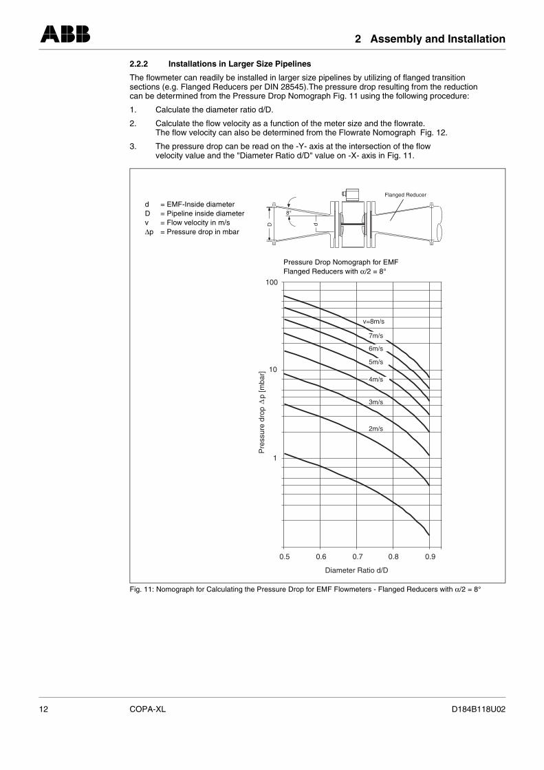
2.2.2 Installations in Larger Size Pipelines
The flowmeter can readily be installed in larger size pipelines by utilizing of flanged transition sections (e.g. Flanged Reducers per DIN 28545).The pressure drop resulting from the reduction can be determined from the Pressure Drop Nomograph Fig. 11 using the following procedure:
1. Calculate the diameter ratio d/D.
2. Calculate the flow velocity as a function of the meter size and the flowrate.The flow velocity can also be determined from the Flowrate Nomograph Fig. 12.
3. The pressure drop can be read on the -Y- axis at the intersection of the flow velocity value and the "Diameter Ratio d/D" value on -X- axis in Fig. 11.
Fig. 11: Nomograph for Calculating the Pressure Drop for EMF Flowmeters - Flanged Reducers with α/2 = 8°
D d
8°
Flanged Reducer
100
10
1
0.5 0.6 0.7 0.8 0.9
v=8m/s
7m/s
6m/s
5m/s
4m/s
3m/s
2m/s
Diameter Ratio d/D
Pre
ssur
e dr
op
p [m
bar]
d = EMF-Inside diameterD = Pipeline inside diameterv = Flow velocity in m/s∆p = Pressure drop in mbar
Pressure Drop Nomograph for EMFFlanged Reducers with α/2 = 8°
12 COPA-XL D184B118U02
2 Assembly and Installation
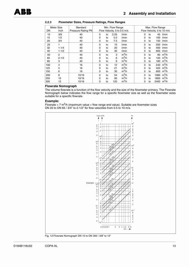
2.2.3 Flowmeter Sizes, Pressure Ratings, Flow Ranges
Flowrate NomographThe volume flowrate is a function of the flow velocity and the size of the flowmeter primary. The FlowrateNomograph below indicates the flow range for a specific flowmeter size as well as the flowmeter sizessuitable for a specific flowrate.
Example:Flowrate = 7 m3/h (maximum value = flow range end value). Suitable are flowmeter sizes DN 20 to DN 65 / 3/4” to 2-1/2” for flow velocities from 0.5 to 10 m/s.
Meter SizeDN Inch
StandardPressure Rating PN
Min. Flow RangeFlow Velocity. 0 to 0.5 m/s
Max. Flow RangeFlow Velocity. 0 to 10 m/s
10 3/815 1/220 3/4
404040
0 to 2.25 l/min0 to 5.0 l/min0 to 7.5 l/min
0 to 45 l/min0 to 100 l/min0 to 150 l/min
25 132 1-1/440 1-1/2
404040
0 to 10 l/min0 to 20 l/min0 to 30 l/min
0 to 200 l/min0 to 400 l/min0 to 600 l/min
50 265 2-1/280 3
404040
0 to 3 m3/h0 to 6 m3/h0 to 9 m3/h
0 to 60 m3/h0 to 120 m3/h0 to 180 m3/h
100 4125 5150 6
161616
0 to 12 m3/h0 to 21 m3/h0 to 30 m3/h
0 to 240 m3/h0 to 420 m3/h0 to 600 m3/h
200 8250 10300 12
10/1610/1610/16
0 to 54 m3/h0 to 90 m3/h0 to 120 m3/h
0 to 1080 m3/h0 to 1800 m3/h0 to 2400 m3/h
Fig. 12:Flowrate Nomograph DN 10 to DN 300 / 3/8” to 12”
102
l/min 3/hm l/s
54
3
2
104
8
6
54
3
2
6
103
8
654
4
3
3
2
2
103
8
654
Example
3
2
8
654
3
2
102
8
654
3
2
108
654
3
2
108
654
3
210-1
8
654
3
2
1
32 4 5 6 8 1010.80.60.5m/s
8
654
3
10-1
18
654
3
2
108
654
3
2
2
8
654
3
2
10
3
8
654
3
2
10
DN 100
DN 125DN 150
DN 200
DN 250DN 300
DN 80
DN 65
DN 50
DN 40
DN 32
DN 25
DN 20
DN 15
DN 10
D184B118U02 COPA-XL 13
3 Programming the Converter
3 Programming the Converter
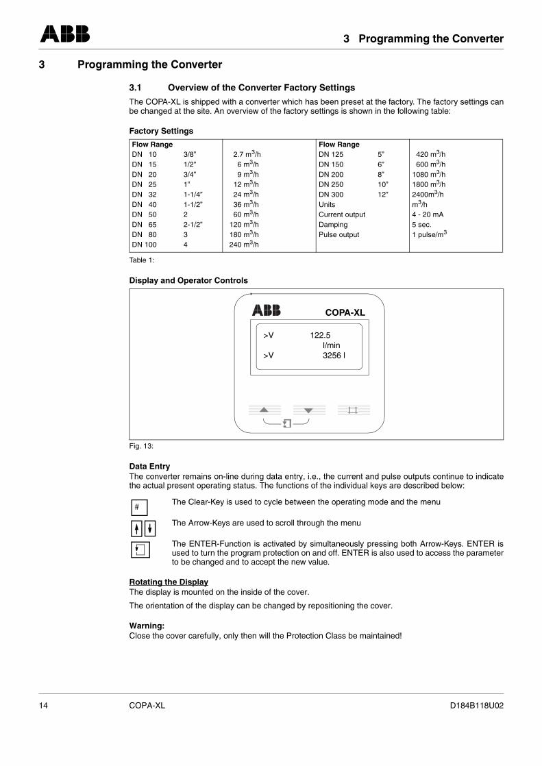
3.1 Overview of the Converter Factory Settings
The COPA-XL is shipped with a converter which has been preset at the factory. The factory settings canbe changed at the site. An overview of the factory settings is shown in the following table:
Factory Settings
Display and Operator Controls
Data EntryThe converter remains on-line during data entry, i.e., the current and pulse outputs continue to indicatethe actual present operating status. The functions of the individual keys are described below:
Rotating the DisplayThe display is mounted on the inside of the cover.
The orientation of the display can be changed by repositioning the cover.
Warning:Close the cover carefully, only then will the Protection Class be maintained!
Flow RangeDN 10 3/8”DN 15 1/2”DN 20 3/4”DN 25 1”DN 32 1-1/4”DN 40 1-1/2”DN 50 2DN 65 2-1/2”DN 80 3DN 100 4
2.7 m3/h6 m3/h9 m3/h
12 m3/h24 m3/h36 m3/h60 m3/h
120 m3/h180 m3/h240 m3/h
Flow RangeDN 125 5”DN 150 6”DN 200 8”DN 250 10”DN 300 12”UnitsCurrent outputDampingPulse output
420 m3/h600 m3/h
1080 m3/h1800 m3/h2400m3/hm3/h4 - 20 mA5 sec.1 pulse/m3
Table 1:
Fig. 13:
The Clear-Key is used to cycle between the operating mode and the menu
The Arrow-Keys are used to scroll through the menu
The ENTER-Function is activated by simultaneously pressing both Arrow-Keys. ENTER isused to turn the program protection on and off. ENTER is also used to access the parameterto be changed and to accept the new value.
COPA-XL
>V 122.5l/min
>V 3256 l
#
14 COPA-XL D184B118U02
4 Data Entry in „Condensed Form“
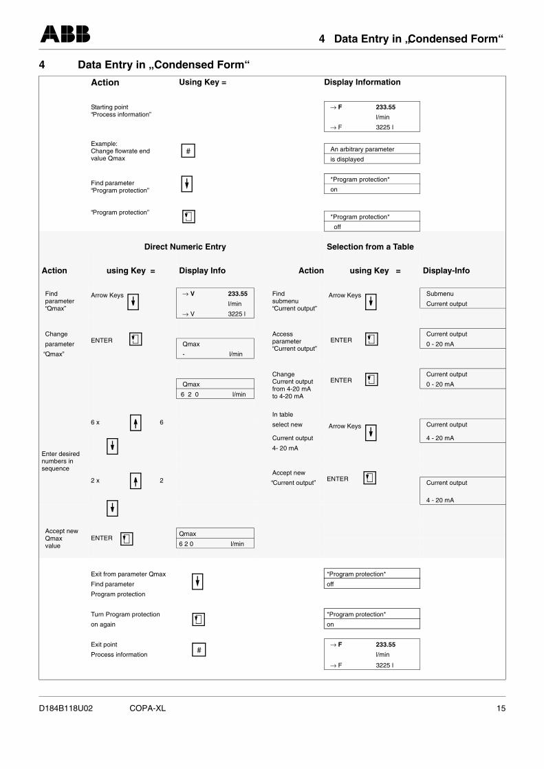
4 Data Entry in „ Condensed Form“
Action Using Key = Display Information
Starting point“Process information”
Example:Change flowrate endvalue Qmax
→ F 233.55
l/min
→ F 3225 l
An arbitrary parameter
is displayed
Find parameter“Program protection”
“Program protection”
*Program protection*
on
*Program protection*
off
Direct Numeric Entry Selection from a Table
Action using Key = Display Info Action using Key = Display-Info
Findparameter“Qmax”
Arrow Keys → V 233.55 Findsubmenu“Current output”
Arrow Keys Submenu
l/min Current output
→ V 3225 l
ChangeENTER
Accessparameter“Current output”
ENTER Current output
parameter Qmax 0 - 20 mA
“Qmax” - l/min
ChangeCurrent outputfrom 4-20 mAto 4-20 mA
ENTER Current output
Qmax 0 - 20 mA
6 2 0 l/min
6 x 6In table
Enter desirednumbers insequence
select new Arrow Keys Current output
Current output 4 - 20 mA
4- 20 mA
2 x 2Accept new
ENTER “Current output” Current output
4 - 20 mA
Accept newQmaxvalue
ENTER Qmax
6 2 0 l/min
Exit from parameter Qmax
*Program protection*
Find parameter off
Program protection
Turn Program protection
*Program protection*
on again on
Exit point
→ F 233.55
Process information l/min
→ F 3225 l
#
#
D184B118U02 COPA-XL 15
5 Data Entry
Parameter Entry Mode
5 Data Entry
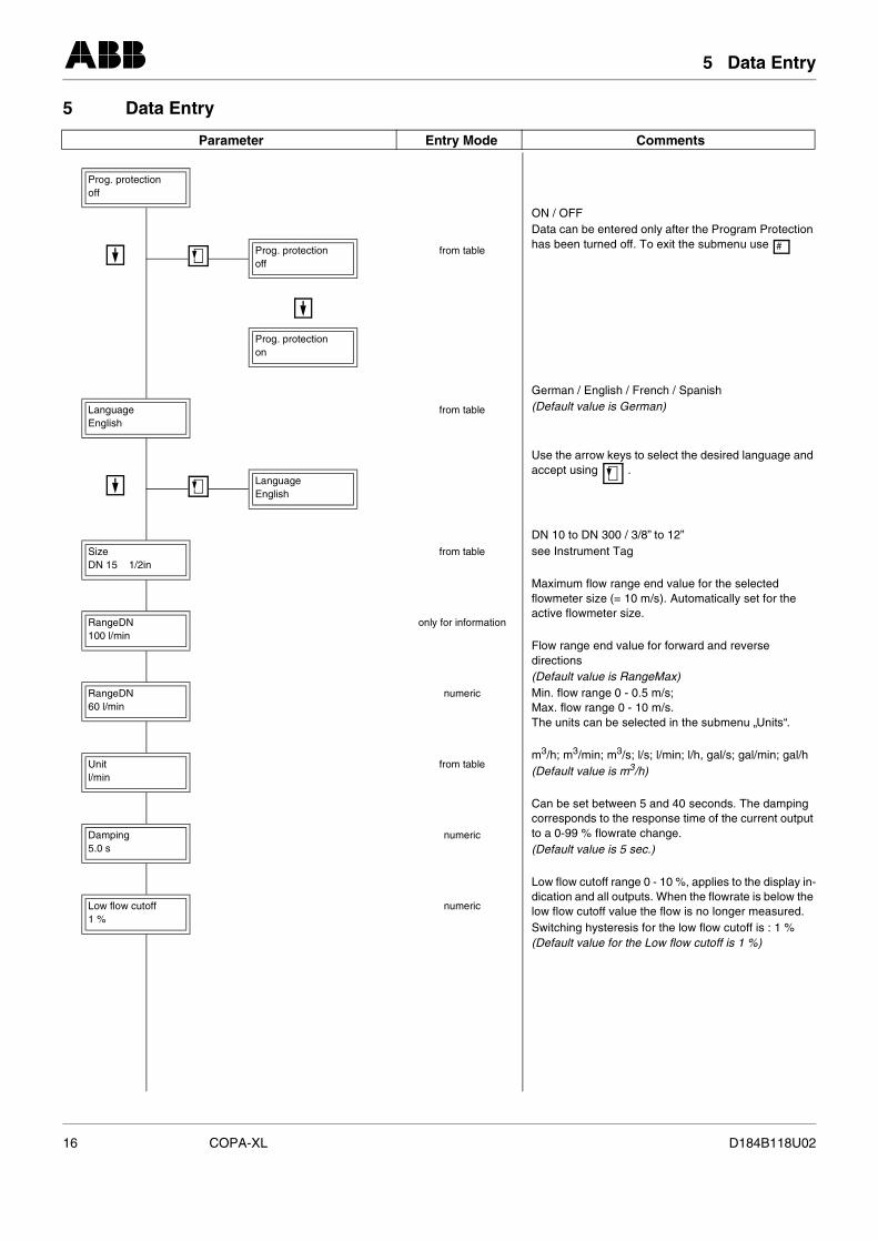
Prog. protectionoff
Prog. protectionoff
from table
Prog. protectionon
Language English
from table
Language English
SizeDN 15 1/2in
from table
RangeDN100 l/min
only for information
RangeDN60 l/min
numeric
Unitl/min
from table
Damping5.0 s
numeric
Low flow cutoff1 %
numeric
ODh
G(D
Ua
Ds
Mfla
Fd(DMMT
m(D
Ccto(D
LdloS(D
16 COPA-XL
Comments
N / OFFata can be entered only after the Program Protection as been turned off. To exit the submenu use
erman / English / French / Spanishefault value is German)
se the arrow keys to select the desired language and ccept using .
N 10 to DN 300 / 3/8” to 12”ee Instrument Tag
aximum flow range end value for the selected owmeter size (= 10 m/s). Automatically set for the ctive flowmeter size.
low range end value for forward and reverse irectionsefault value is RangeMax)in. flow range 0 - 0.5 m/s; ax. flow range 0 - 10 m/s. he units can be selected in the submenu „Units“.
3/h; m3/min; m3/s; l/s; l/min; l/h, gal/s; gal/min; gal/hefault value is m3/h)
an be set between 5 and 40 seconds. The damping orresponds to the response time of the current output a 0-99 % flowrate change. efault value is 5 sec.)
ow flow cutoff range 0 - 10 %, applies to the display in-ication and all outputs. When the flowrate is below the w flow cutoff value the flow is no longer measured.witching hysteresis for the low flow cutoff is : 1 %efault value for the Low flow cutoff is 1 %)
#
D184B118U02
5 Data Entry
Parameter Entry Mode
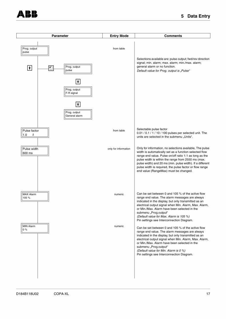
Prog. outputpulse
from table
Prog. outputpulse
Prog. outputF-R signal
Prog. outputGeneral alarm
Pulse factor1.0 /l
from table
Pulse width600 ms
only for information
MAX Alarm105 %
numeric
MIN Alarm0 %
numeric
SsgD
S0u
Owrapppe
Craineos(DP
Craineos(DP
D184B118U02 COPA-XL
Comments
elections available are: pulse output; fwd/rev direction ignal; min. alarm; max. alarm; min./max. alarm;eneral alarm or no function.efault value for Prog. output is „Pulse“
electable pulse factor .01 / 0.1 / 1 / 10 / 100 pulses per selected unit. The nits are selected in the submenu „Units“.
nly for information, no selections available, The pulse idth is automatically set as a function selected flow nge end value. Pulse on/off ratio 1:1 as long as the
ulse width is within the range from 2550 ms (max. ulse width) and 20 ms (min. pulse width). If a different ulse width is required, the pulse factor or flow range nd value (RangeMax) must be changed.
an be set between 0 and 105 % of the active flow nge end value. The alarm messages are always dicated in the display, but only transmitted as an lectrical output signal when Min. Alarm, Max. Alarm, r Min./Max. Alarm have been selected in the ubmenu „Prog.output“
efault value for Max. Alarm is 105 %)in settings see Interconnection Diagram.
an be set between 0 and 105 % of the active flow nge end value. The alarm messages are always dicated in the display, but only transmitted as an lectrical output signal when Min. Alarm, Max. Alarm, r Min./Max. Alarm have been selected in the ubmenu „Prog.output“
efault value for Min. Alarm is 0 %)in settings see Interconnection Diagram.
17
5 Data Entry
Parameter Entry Mode
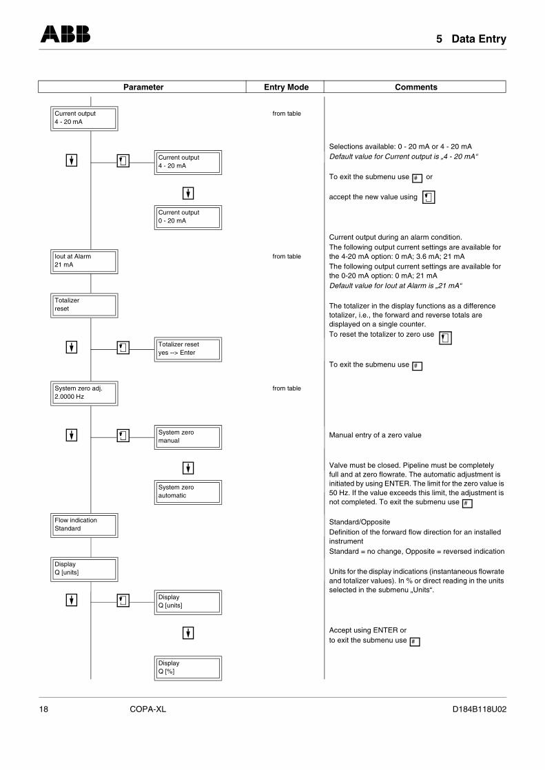
Current output4 - 20 mA
from table
Current output4 - 20 mA
Current output0 - 20 mA
Iout at Alarm21 mA
from table
Totalizerreset
Totalizer resetyes --> Enter
System zero adj.2.0000 Hz
from table
System zeromanual
System zeroautomatic
Flow indicationStandard
DisplayQ [units]
DisplayQ [units]
DisplayQ [%]
SD
T
a
CTthTthD
TtodT
T
M
Vfuin5n
SDinS
Uas
Ato
18 COPA-XL
Comments
elections available: 0 - 20 mA or 4 - 20 mAefault value for Current output is „4 - 20 mA“
o exit the submenu use or
ccept the new value using
urrent output during an alarm condition.he following output current settings are available for e 4-20 mA option: 0 mA; 3.6 mA; 21 mAhe following output current settings are available for e 0-20 mA option: 0 mA; 21 mAefault value for Iout at Alarm is „21 mA“
he totalizer in the display functions as a difference talizer, i.e., the forward and reverse totals are isplayed on a single counter. o reset the totalizer to zero use
o exit the submenu use
anual entry of a zero value
alve must be closed. Pipeline must be completely ll and at zero flowrate. The automatic adjustment is itiated by using ENTER. The limit for the zero value is 0 Hz. If the value exceeds this limit, the adjustment is ot completed. To exit the submenu use
tandard/Oppositeefinition of the forward flow direction for an installed strumenttandard = no change, Opposite = reversed indication
nits for the display indications (instantaneous flowrate nd totalizer values). In % or direct reading in the units elected in the submenu „Units“.
ccept using ENTER or exit the submenu use
#
#
#
#
D184B118U02
5 Data Entry
Parameter Entry Mode
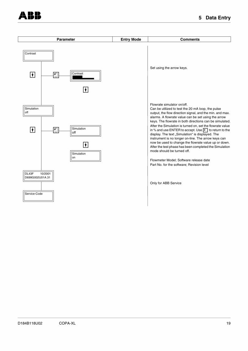
Contrast
Contrast
Simulationoff
Simulationoff
Simulationon
DL43F 10/2001D699G002U01A.31
Service-Code
S
FCoakAindinnAm
FP
O
D184B118U02 COPA-XL
Comments
et using the arrow keys.
lowrate simulator on/off.an be utilized to test the 20 mA loop, the pulse utput, the flow direction signal, and the min. and max. larms. A flowrate value can be set using the arrow eys. The flowrate in both directions can be simulated.fter the Simulation is turned on, set the flowrate value % and use ENTER to accept. Use to return to the isplay. The text „Simulation“ is displayed. The strument is no longer on-line. The arrow keys can ow be used to change the flowrate value up or down. fter the test phase has been completed the Simulation ode should be turned off.
lowmeter Model; Software release dateart No. for the software; Revision level
nly for ABB Service
#
19
6 Circuit Boards
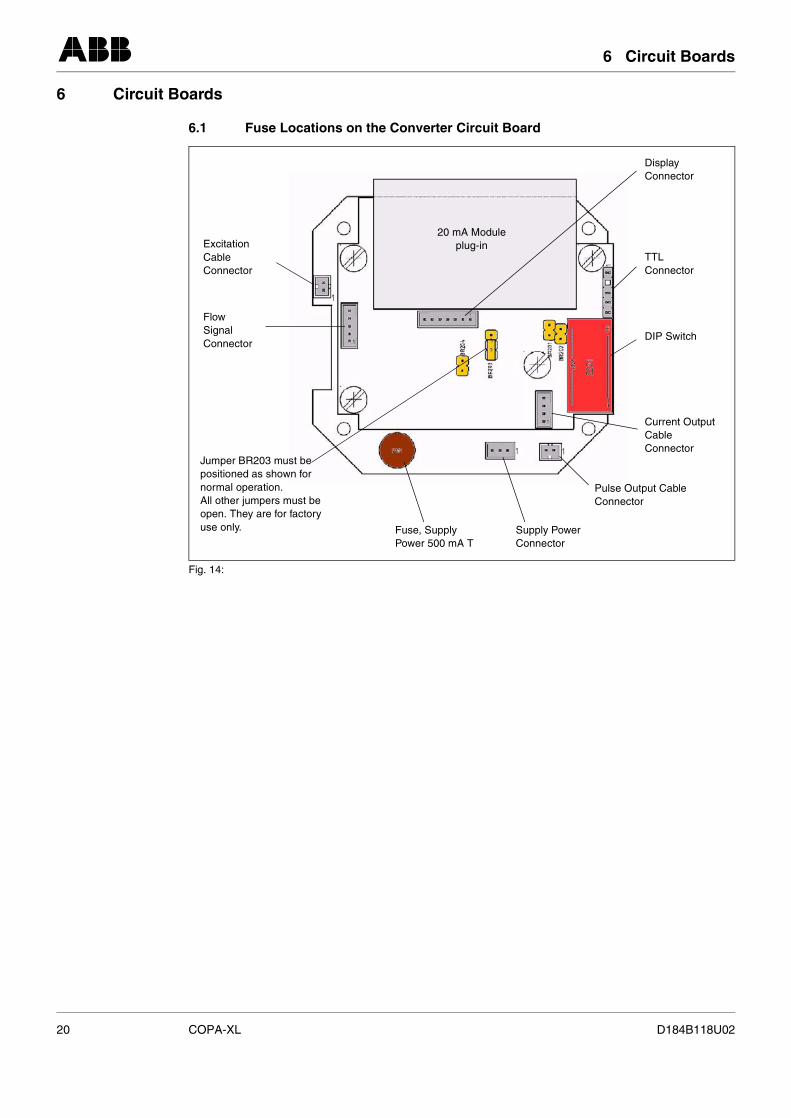
6 Circuit Boards
6.1 Fuse Locations on the Converter Circuit Board
Fig. 14:
Current Output Cable Connector
DIP Switch
TTLConnector
DisplayConnector
Pulse Output CableConnector
Excitation Cable Connector
FlowSignalConnector
Jumper BR203 must be positioned as shown for normal operation.All other jumpers must be open. They are for factory use only. Fuse, Supply
Power 500 mA TSupply PowerConnector
20 mA Moduleplug-in
20 COPA-XL D184B118U02
7 Ordering Information
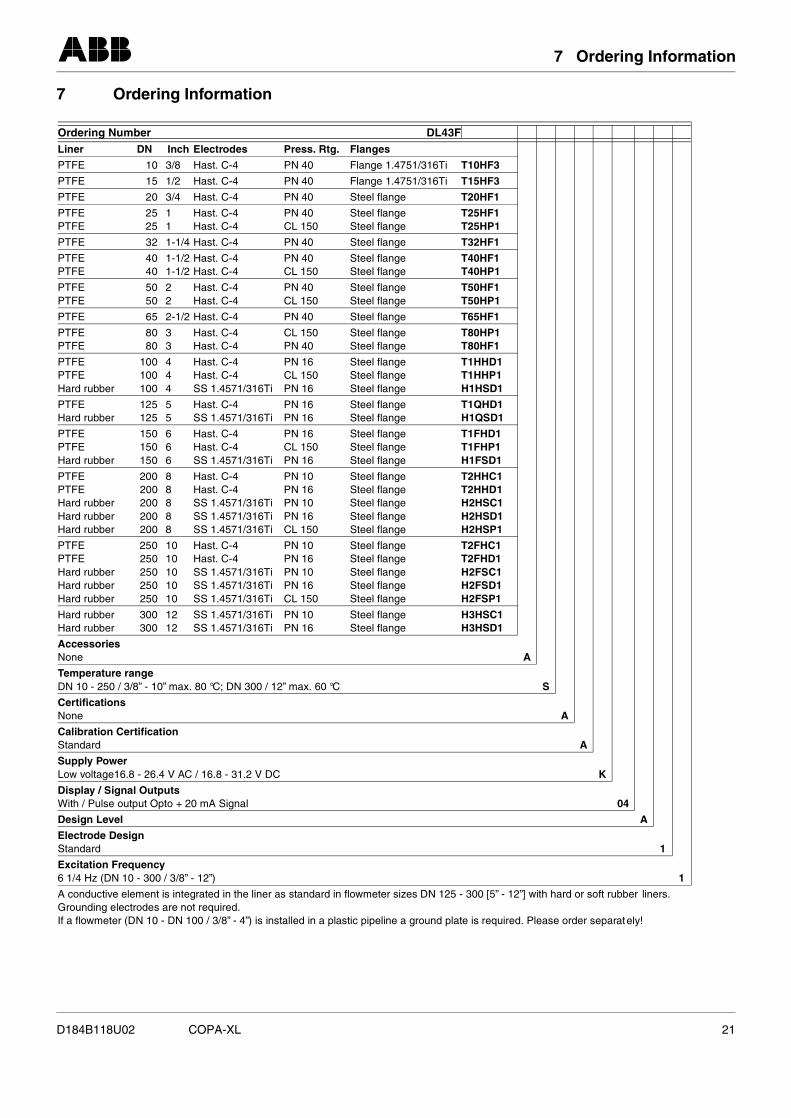
7 Ordering Information
A conductive element is integrated in the liner as standard in flowmeter sizes DN 125 - 300 [5” - 12”] with hard or soft rubber liners. Grounding electrodes are not required.If a flowmeter (DN 10 - DN 100 / 3/8” - 4”) is installed in a plastic pipeline a ground plate is required. Please order separately!
Ordering Number DL43FLiner DN Inch Electrodes Press. Rtg. Flanges
PTFE 10 3/8 Hast. C-4 PN 40 Flange 1.4751/316Ti T10HF3
PTFE 15 1/2 Hast. C-4 PN 40 Flange 1.4751/316Ti T15HF3
PTFE 20 3/4 Hast. C-4 PN 40 Steel flange T20HF1
PTFEPTFE
25 1 25 1
Hast. C-4Hast. C-4
PN 40CL 150
Steel flangeSteel flange
T25HF1T25HP1
PTFE 32 1-1/4 Hast. C-4 PN 40 Steel flange T32HF1
PTFEPTFE
40 1-1/2 40 1-1/2
Hast. C-4Hast. C-4
PN 40CL 150
Steel flangeSteel flange
T40HF1T40HP1
PTFEPTFE
50 2 50 2
Hast. C-4Hast. C-4
PN 40CL 150
Steel flangeSteel flange
T50HF1T50HP1
PTFE 65 2-1/2 Hast. C-4 PN 40 Steel flange T65HF1
PTFEPTFE
80 3 80 3
Hast. C-4Hast. C-4
CL 150PN 40
Steel flangeSteel flange
T80HP1T80HF1
PTFEPTFEHard rubber
100 4 100 4 100 4
Hast. C-4Hast. C-4SS 1.4571/316Ti
PN 16CL 150PN 16
Steel flangeSteel flangeSteel flange
T1HHD1T1HHP1H1HSD1
PTFEHard rubber
125 5 125 5
Hast. C-4SS 1.4571/316Ti
PN 16PN 16
Steel flangeSteel flange
T1QHD1H1QSD1
PTFEPTFEHard rubber
150 6 150 6 150 6
Hast. C-4Hast. C-4SS 1.4571/316Ti
PN 16CL 150PN 16
Steel flangeSteel flangeSteel flange
T1FHD1T1FHP1H1FSD1
PTFEPTFE Hard rubberHard rubberHard rubber
200 8200 8200 8200 8200 8
Hast. C-4Hast. C-4SS 1.4571/316TiSS 1.4571/316TiSS 1.4571/316Ti
PN 10PN 16PN 10PN 16CL 150
Steel flangeSteel flangeSteel flangeSteel flangeSteel flange
T2HHC1T2HHD1H2HSC1H2HSD1H2HSP1
PTFEPTFEHard rubberHard rubberHard rubber
250 10250 10250 10250 10250 10
Hast. C-4Hast. C-4SS 1.4571/316TiSS 1.4571/316TiSS 1.4571/316Ti
PN 10PN 16PN 10PN 16CL 150
Steel flangeSteel flangeSteel flangeSteel flangeSteel flange
T2FHC1T2FHD1H2FSC1H2FSD1H2FSP1
Hard rubberHard rubber
300 12 300 12
SS 1.4571/316TiSS 1.4571/316Ti
PN 10PN 16
Steel flangeSteel flange
H3HSC1H3HSD1
AccessoriesNone A
Temperature rangeDN 10 - 250 / 3/8” - 10” max. 80 °C; DN 300 / 12” max. 60 °C S
CertificationsNone A
Calibration CertificationStandard A
Supply PowerLow voltage16.8 - 26.4 V AC / 16.8 - 31.2 V DC K
Display / Signal OutputsWith / Pulse output Opto + 20 mA Signal 04
Design Level A
Electrode DesignStandard 1
Excitation Frequency6 1/4 Hz (DN 10 - 300 / 3/8” - 12”) 1
D184B118U02 COPA-XL 21

8 Error Messages
8 Error MessagesDescriptions of the error messages for the Error Codes shown in the display are listed below.
There are two error messages possible in the COPA-XL.
Error 1is displayed when the A/D converter is saturated.
The current output in response to Error 1 is set to the value selected in the submenu „Iout at Alarm“.
When the 4 - 20 mA current output option is selected the following current values can be selected in thesubmenu „Iout at Alarm“, 0, 3.6 or 21 mA.
When the 0 - 20 mA current output option is selected the following current values can be selected in thesubmenu „Iout at Alarm“, 0, or 21 mA.
Error 3is displayed when the flow range is exceeded.
This error occurs when the actual flowrate is greater than 105 % of the flow range end value.
During this error condition the current output is always set to 21 mA.
22 COPA-XL D184B118U02
9 Accuracy
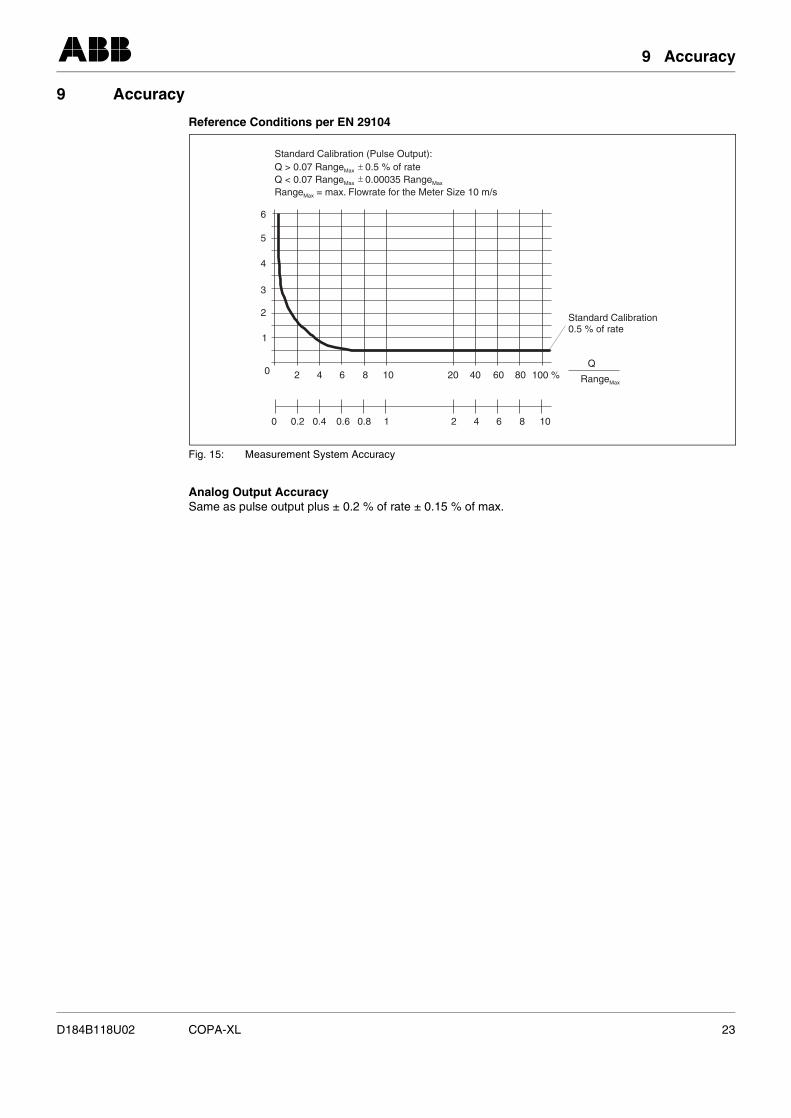
9 Accuracy
Reference Conditions per EN 29104
Analog Output AccuracySame as pulse output plus ± 0.2 % of rate ± 0.15 % of max.
Fig. 15: Measurement System Accuracy
6
5
4
3
2
1
0 2 4 6 8 10 20 40 60 80 100 %
2 4 6 8 10
Standard Calibration0.5 % of rate
0 0.2 0.4 0.6 0.8 1
Q
RangeMax
Standard Calibration (Pulse Output):Q > 0.07 Range 0.5 % of rateQ < 0.07 0.00035
= max. Flowrate for the Meter Size 10 m/s
Max
Range RangeRange
Max Max
Max
D184B118U02 COPA-XL 23
10 Safety Relevant Portion of the Instruction Bulletin
10 Safety Relevant Portion of the Instruction Bulletin
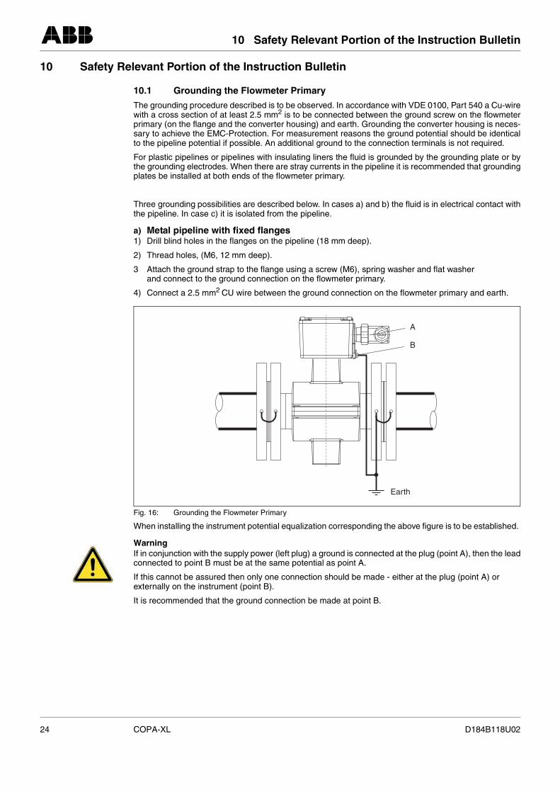
10.1 Grounding the Flowmeter Primary
The grounding procedure described is to be observed. In accordance with VDE 0100, Part 540 a Cu-wirewith a cross section of at least 2.5 mm2 is to be connected between the ground screw on the flowmeterprimary (on the flange and the converter housing) and earth. Grounding the converter housing is neces-sary to achieve the EMC-Protection. For measurement reasons the ground potential should be identicalto the pipeline potential if possible. An additional ground to the connection terminals is not required.
For plastic pipelines or pipelines with insulating liners the fluid is grounded by the grounding plate or bythe grounding electrodes. When there are stray currents in the pipeline it is recommended that groundingplates be installed at both ends of the flowmeter primary.
Three grounding possibilities are described below. In cases a) and b) the fluid is in electrical contact withthe pipeline. In case c) it is isolated from the pipeline.
a) Metal pipeline with fixed flanges1) Drill blind holes in the flanges on the pipeline (18 mm deep).
2) Thread holes, (M6, 12 mm deep).
3 Attach the ground strap to the flange using a screw (M6), spring washer and flat washer and connect to the ground connection on the flowmeter primary.
4) Connect a 2.5 mm2 CU wire between the ground connection on the flowmeter primary and earth.
When installing the instrument potential equalization corresponding the above figure is to be established.
WarningIf in conjunction with the supply power (left plug) a ground is connected at the plug (point A), then the leadconnected to point B must be at the same potential as point A.
If this cannot be assured then only one connection should be made - either at the plug (point A) or externally on the instrument (point B).
It is recommended that the ground connection be made at point B.
Fig. 16: Grounding the Flowmeter Primary
A
B
Earth
24 COPA-XL D184B118U02
10 Safety Relevant Portion of the Instruction Bulletin
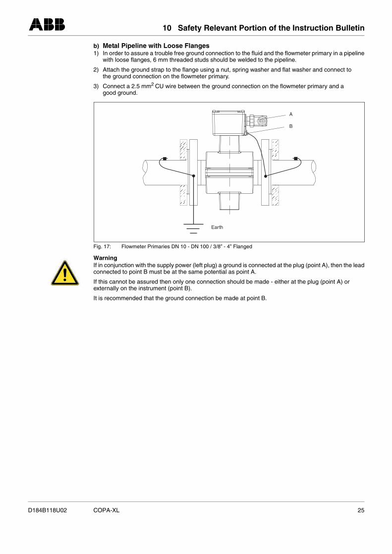
b) Metal Pipeline with Loose Flanges1) In order to assure a trouble free ground connection to the fluid and the flowmeter primary in a pipeline
with loose flanges, 6 mm threaded studs should be welded to the pipeline.
2) Attach the ground strap to the flange using a nut, spring washer and flat washer and connect to the ground connection on the flowmeter primary.
3) Connect a 2.5 mm2 CU wire between the ground connection on the flowmeter primary and a good ground.
WarningIf in conjunction with the supply power (left plug) a ground is connected at the plug (point A), then the leadconnected to point B must be at the same potential as point A.
If this cannot be assured then only one connection should be made - either at the plug (point A) or externally on the instrument (point B).
It is recommended that the ground connection be made at point B.
Fig. 17: Flowmeter Primaries DN 10 - DN 100 / 3/8” - 4” Flanged
A
B
Earth
D184B118U02 COPA-XL 25
10 Safety Relevant Portion of the Instruction Bulletin
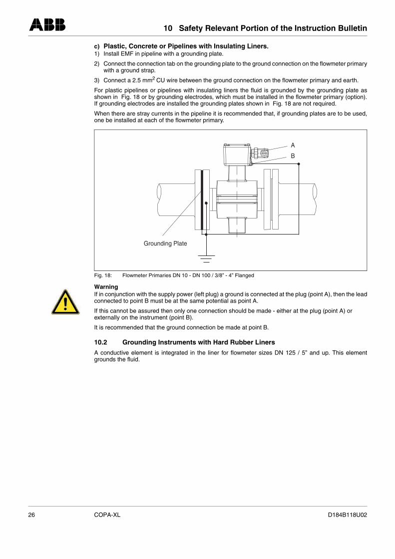
c) Plastic, Concrete or Pipelines with Insulating Liners. 1) Install EMF in pipeline with a grounding plate.
2) Connect the connection tab on the grounding plate to the ground connection on the flowmeter primarywith a ground strap.
3) Connect a 2.5 mm2 CU wire between the ground connection on the flowmeter primary and earth.
For plastic pipelines or pipelines with insulating liners the fluid is grounded by the grounding plate asshown in Fig. 18 or by grounding electrodes, which must be installed in the flowmeter primary (option).If grounding electrodes are installed the grounding plates shown in Fig. 18 are not required.
When there are stray currents in the pipeline it is recommended that, if grounding plates are to be used,one be installed at each of the flowmeter primary.
WarningIf in conjunction with the supply power (left plug) a ground is connected at the plug (point A), then the leadconnected to point B must be at the same potential as point A.
If this cannot be assured then only one connection should be made - either at the plug (point A) or externally on the instrument (point B).
It is recommended that the ground connection be made at point B.
10.2 Grounding Instruments with Hard Rubber Liners
A conductive element is integrated in the liner for flowmeter sizes DN 125 / 5” and up. This elementgrounds the fluid.
Fig. 18: Flowmeter Primaries DN 10 - DN 100 / 3/8” - 4” Flanged
A
B
Grounding Plate
26 COPA-XL D184B118U02
11 Electrical Connections
11 Electrical Connections
11.1 Interconnection Diagram
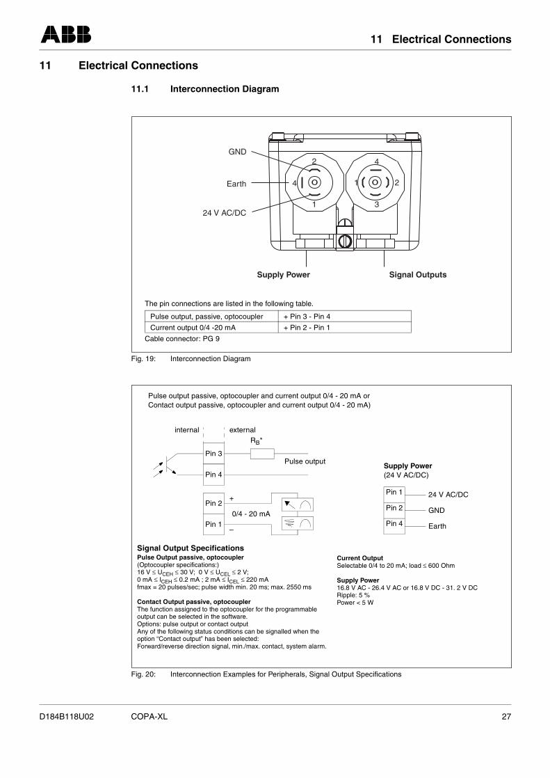
Fig. 19: Interconnection Diagram
Fig. 20: Interconnection Examples for Peripherals, Signal Output Specifications
GND
4
4
3
2
2
1
1
Earth
Supply Power Signal Outputs
24 V AC/DC
The pin connections are listed in the following table.
Cable connector: PG 9
Pulse output, passive, optocoupler + Pin 3 - Pin 4
Current output 0/4 -20 mA + Pin 2 - Pin 1
Pin 3
Pin 4
externalinternal
Pulse output passive, optocoupler and current output 0/4 - 20 mA or Contact output passive, optocoupler and current output 0/4 - 20 mA)
RB*
Pin 2
Pin 1
Pulse output
–
+
0/4 - 20 mAPin 4
Pin 1
Pin 2
24 V AC/DC
GND
Earth
Supply Power(24 V AC/DC)
Signal Output SpecificationsPulse Output passive, optocoupler (Optocoupler specifications:)16 V ≤ UCEH ≤ 30 V; 0 V ≤ UCEL ≤ 2 V; 0 mA ≤ ICEH ≤ 0.2 mA ; 2 mA ≤ ICEL ≤ 220 mAfmax = 20 pulses/sec; pulse width min. 20 ms; max. 2550 ms
Contact Output passive, optocoupler The function assigned to the optocoupler for the programmableoutput can be selected in the software.Options: pulse output or contact outputAny of the following status conditions can be signalled when the option “Contact output” has been selected:Forward/reverse direction signal, min./max. contact, system alarm.
Current Output Selectable 0/4 to 20 mA; load ≤ 600 Ohm
Supply Power16.8 V AC - 26.4 V AC or 16.8 V DC - 31. 2 V DCRipple: 5 %Power < 5 W
D184B118U02 COPA-XL 27
11 Electrical Connections
11.2 Signal Outputs and Supply Power
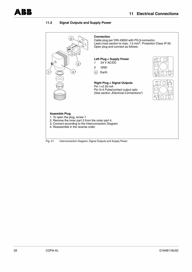
Fig. 21: Interconnection Diagram; Signal Outputs and Supply Power
1
2
1
24
3
2
3
41
ConnectionCable plug per DIN 43650 with PG 9-connector,Lead cross section to max. 1.5 mm2, Protection Class IP 65Open plug and connect as follows:
Left Plug = Supply Power1 24 V AC/DC
2 GND
Earth
Right Plug = Signal OutputsPin 1+2 20 mA Pin 3+4 Pulse/contact output opto(See section „Electrical Connections“)
Assemble Plug1. To open the plug, screw 1.2. Remove the inner part 3 from the outer part 4.3. Connect according to the Interconnection Diagram.4. Reassemble in the reverse order.
28 COPA-XL D184B118U02
12 Start-Up
12 Start-Up
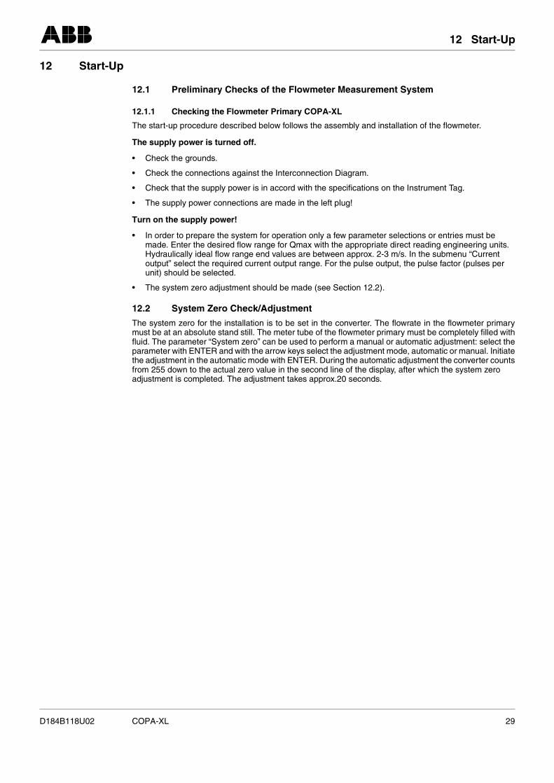
12.1 Preliminary Checks of the Flowmeter Measurement System
12.1.1 Checking the Flowmeter Primary COPA-XL
The start-up procedure described below follows the assembly and installation of the flowmeter.
The supply power is turned off.
• Check the grounds.
• Check the connections against the Interconnection Diagram.
• Check that the supply power is in accord with the specifications on the Instrument Tag.
• The supply power connections are made in the left plug!
Turn on the supply power!
• In order to prepare the system for operation only a few parameter selections or entries must be made. Enter the desired flow range for Qmax with the appropriate direct reading engineering units. Hydraulically ideal flow range end values are between approx. 2-3 m/s. In the submenu “Current output” select the required current output range. For the pulse output, the pulse factor (pulses per unit) should be selected.
• The system zero adjustment should be made (see Section 12.2).
12.2 System Zero Check/Adjustment
The system zero for the installation is to be set in the converter. The flowrate in the flowmeter primarymust be at an absolute stand still. The meter tube of the flowmeter primary must be completely filled withfluid. The parameter “System zero” can be used to perform a manual or automatic adjustment: select theparameter with ENTER and with the arrow keys select the adjustment mode, automatic or manual. Initiatethe adjustment in the automatic mode with ENTER. During the automatic adjustment the converter countsfrom 255 down to the actual zero value in the second line of the display, after which the system zero adjustment is completed. The adjustment takes approx.20 seconds.
D184B118U02 COPA-XL 29
12 Start-Up
12.3 Maintenance / Repair
The flowmeter primary is essentially maintenance free. An annually check of the ambient conditions (air circulation, humidity), seal integrity of the process connections, cable connectors and cover screws,functional reliability of the supply voltage, the lightning protection and the grounds should be conducted.
All repairs or maintenance tasks should be performed only by qualified user service personnel.
Observe the note (Hazardous Material Regulations) when the flowmeter is to be returned to the ABB Automation Products factory for repair!
Warning / Information for Opening the Housing
The following information must be considered when the converter housing is to be opened:
• All connections must be potential free.
• When the housing is opened the EMC-Protection is voided.
12.4 Rotating the Display
The display is mounted on the inside of the cover. The orientation of the display can be changed by repositioning the cover.
When completed, carefully reinstall the cover screws. Check that the gaskets are correctly seated. Onlythen will Protection Class IP 67 be maintained.
Warning / General Information
In the event that the forward and reverse flow indicators in the display do not agree with the actual flowdirection through the flowmeter, the parameter “Flow direction” can be used to reverse the direction indicators by switching from “normal” to “inverse”.
12.5 Replaceable Parts, Flowmeter Primary
If repairs to the liner, electrodes or magnet coils are required, the flowmeter primary should be returnedto the ABB Automation Products factory in Göttingen, Germany. Observe the Hazardous Material Regu-lations information.
30 COPA-XL D184B118U02
13 Converter Specifications
13 Converter Specifications
Optocoupler fora) Pulse Output passive
(optocoupler specifications:)16 V ≤ UCEH ≤ 30 V; 0 V ≤ UCEL ≤ 2 V; 0 mA ≤ ICEH ≤ 0.2 mA ; 2 mA ≤ ICEL ≤ 220 mAfmax = 20 pulses/sec; pulse width min. 20 ms; max. 2550 ms
or
b) Contact Output passiveThe function assigned to the output is selectable: forward/reverse flow direction signal, min./ max.contact, system alarm. For optocoupler specifications: see pulse output
The function assigned to the optocoupler output can be selected at the site in the software: min./max.alarm etc. The optocoupler output can be assigned to the function “Pulse Output” or the function “ContactOutput”.
Current OutputSelectable 0/4 to 20 mA; load ≤ 600 Ohm
Alarm SignalThe contact output (optocoupler) can be configured as a system alarm. For optocoupler specifications: see pulse output
LoadMax. load for the current output: ≤ 600 Ohm
Low Flow CutoffThe low flow cutoff value can be set by the user.
Factory default setting: 1%
Reproducibility≤ 0.2 % of rate
Response TimeFor a step change 0-99 % (corresp. 5 ) ≥ 5 sExcitation frequency : 6 1/4 Hz
Ambient Conditions
Ambient Temperature-25 °C to 50 °C
Protection ClassIP 65 (per EN 60529)
Electromagnetic CompatibilityThe instrument corresponds to the NAMUR-Recommendations NE21. Electromagnetic Compatibility ofEquipment in Processes and Laboratories 5/93 and EMC Guideline 89/336/EWG (EN50081-1, EN 50082-2).
Warning
The EMC-Protection is voided when the housing cover is opened.
ConductivityMin. 20 µS/cm
τ
D184B118U02 COPA-XL 31

ABB Automation Products GmbHDransfelder Str. 2, D-37079 GoettingenTel.: +49 (0) 5 51 9 05 - 0Fax: +49 (0) 5 51 9 05 - 777http://www.abb.com
Rights to make technical revisions reserved.
This document is copyrighted. Translating, copying or distributing it in any form – as well as revisions or excerpts – and spe cifically including reprints, photomechanical or electronic reproductions or storage in data processing systems or data networks is strictly prohibited without the express permission from the owner of the copyright and any violations will be prosecuted.
Printed in the Fed. R. of GermanyD184B118U02 Rev. 01
Edition 11.01