Embed Size (px)
Citation preview
Aastra Model 6867i SIP IP Phone
Installation Guide
41-001507-00 REV00 – 04.2014

ii 41-001507-00 REV00 – 04.2014
Software License AgreementAastra, hereinafter known as "Seller", grants to Customer a personal, worldwide, non-transferable, non-sublicenseable and non-exclusive, restricted use license to use Software in object form solely with the Equipment for which the Soft-ware was intended. This Product may integrate programs, licensed to Aastra by third party Suppliers, for distribution under the terms of this agreement. These programs are confidential and proprietary, and are protected as such by copy-right law as unpublished works and by international treaties to the fullest extent under the applicable law of the jurisdic-tion of the Customer. In addition, these confidential and proprietary programs are works conforming to the require-ments of Section 401 of title 17 of the United States Code. Customer shall not disclose to any third party such confiden-tial and proprietary programs and information and shall not export licensed Software to any country except in accord-ance with United States Export laws and restrictions.
Customer agrees to not reverse engineer, decompile, disassemble or display Software furnished in object code form. Customer shall not modify, copy, reproduce, distribute, transcribe, translate or reduce to electronic medium or machine readable form or language, derive source code without the express written consent of the Seller and its Suppliers, or dis-seminate or otherwise disclose the Software to third parties. All Software furnished hereunder (whether or not part of firmware), including all copies thereof, are and shall remain the property of Seller and its Suppliers and are subject to the terms and conditions of this agreement. All rights reserved.
Customer's use of this software shall be deemed to reflect Customer's agreement to abide by the terms and conditions contained herein. Removal or modification of trademarks, copyright notices, logos, etc., or the use of Software on any Equipment other than that for which it is intended, or any other material breach of this Agreement, shall automatically terminate this license. If this Agreement is terminated for breach, Customer shall immediately discontinue use and destroy or return to Seller all licensed software and other confidential or proprietary information of Seller. In no event shall Seller or its suppliers or licensors be liable for any damages whatsoever (including without limitation, damages for loss of business profits, business interruption, loss of business information, other pecuniary loss, or consequential dam-ages) arising out of the use of or inability to use the software, even if Seller has been advised of the possibility of such damages.
Content
Software License Agreement . . . . . . . . . . . . . . . . . . . . . . . . . . . . . . . . . . . . . . . . . . . . . . . . . . . . . . . . . . . . . . . . . . . . . . . . . . . . . . . .ii
Welcome . . . . . . . . . . . . . . . . . . . . . . . . . . . . . . . . . . . . . . . . . . . . . . . . . . . . . . . . . . . . . . . . . . . . . . . . . . . . . . . . . . . . . . . . . . . . . . . . . . . . . . . . .1
Phone Features. . . . . . . . . . . . . . . . . . . . . . . . . . . . . . . . . . . . . . . . . . . . . . . . . . . . . . . . . . . . . . . . . . . . . . . . . . . . . . . . . . . . . . . . . . . . . . 1
Requirements . . . . . . . . . . . . . . . . . . . . . . . . . . . . . . . . . . . . . . . . . . . . . . . . . . . . . . . . . . . . . . . . . . . . . . . . . . . . . . . . . . . . . . . . . . . . . . . 1
About This Guide . . . . . . . . . . . . . . . . . . . . . . . . . . . . . . . . . . . . . . . . . . . . . . . . . . . . . . . . . . . . . . . . . . . . . . . . . . . . . . . . . . . . . . . . . . . . 1
Phone Parts . . . . . . . . . . . . . . . . . . . . . . . . . . . . . . . . . . . . . . . . . . . . . . . . . . . . . . . . . . . . . . . . . . . . . . . . . . . . . . . . . . . . . . . . . . . . . . . . . . . . .2
Additional Accessories (Not Included) . . . . . . . . . . . . . . . . . . . . . . . . . . . . . . . . . . . . . . . . . . . . . . . . . . . . . . . . . . . . . . . . . . . . . . . 2
IP Phone Keys . . . . . . . . . . . . . . . . . . . . . . . . . . . . . . . . . . . . . . . . . . . . . . . . . . . . . . . . . . . . . . . . . . . . . . . . . . . . . . . . . . . . . . . . . . . . . . . . . . .3
Key Panel . . . . . . . . . . . . . . . . . . . . . . . . . . . . . . . . . . . . . . . . . . . . . . . . . . . . . . . . . . . . . . . . . . . . . . . . . . . . . . . . . . . . . . . . . . . . . . . . . . . 3
Key Description . . . . . . . . . . . . . . . . . . . . . . . . . . . . . . . . . . . . . . . . . . . . . . . . . . . . . . . . . . . . . . . . . . . . . . . . . . . . . . . . . . . . . . . . . . . . . 4
Installation and Setup . . . . . . . . . . . . . . . . . . . . . . . . . . . . . . . . . . . . . . . . . . . . . . . . . . . . . . . . . . . . . . . . . . . . . . . . . . . . . . . . . . . . . . . .6
Direct or Shared Network Connection . . . . . . . . . . . . . . . . . . . . . . . . . . . . . . . . . . . . . . . . . . . . . . . . . . . . . . . . . . . . . . . . . . . . . . . 6
Connecting to the Network and to Power . . . . . . . . . . . . . . . . . . . . . . . . . . . . . . . . . . . . . . . . . . . . . . . . . . . . . . . . . . . . . . . . . . . . 7
Connecting a Handset or Headset . . . . . . . . . . . . . . . . . . . . . . . . . . . . . . . . . . . . . . . . . . . . . . . . . . . . . . . . . . . . . . . . . . . . . . . . . . . 8
Installation. . . . . . . . . . . . . . . . . . . . . . . . . . . . . . . . . . . . . . . . . . . . . . . . . . . . . . . . . . . . . . . . . . . . . . . . . . . . . . . . . . . . . . . . . . . . . . . . . . 9
Accessing Your Options via the Phone UI . . . . . . . . . . . . . . . . . . . . . . . . . . . . . . . . . . . . . . . . . . . . . . . . . . . . . . . . . . . . . . . . . . .16
Accessing Your Options via the Aastra Web UI . . . . . . . . . . . . . . . . . . . . . . . . . . . . . . . . . . . . . . . . . . . . . . . . . . . . . . . . . . . . . .16
Troubleshooting Solutions. . . . . . . . . . . . . . . . . . . . . . . . . . . . . . . . . . . . . . . . . . . . . . . . . . . . . . . . . . . . . . . . . . . . . . . . . . . . . . . . . 18
Limited Warranty . . . . . . . . . . . . . . . . . . . . . . . . . . . . . . . . . . . . . . . . . . . . . . . . . . . . . . . . . . . . . . . . . . . . . . . . . . . . . . . . . . . . . . . . . . . . 19
Exclusions . . . . . . . . . . . . . . . . . . . . . . . . . . . . . . . . . . . . . . . . . . . . . . . . . . . . . . . . . . . . . . . . . . . . . . . . . . . . . . . . . . . . . . . . . . . . . . . . . .19
Warranty Repair Services. . . . . . . . . . . . . . . . . . . . . . . . . . . . . . . . . . . . . . . . . . . . . . . . . . . . . . . . . . . . . . . . . . . . . . . . . . . . . . . . . . .19
After Warranty Service . . . . . . . . . . . . . . . . . . . . . . . . . . . . . . . . . . . . . . . . . . . . . . . . . . . . . . . . . . . . . . . . . . . . . . . . . . . . . . . . . . . . .19
Limited Warranty (Australia Only) . . . . . . . . . . . . . . . . . . . . . . . . . . . . . . . . . . . . . . . . . . . . . . . . . . . . . . . . . . . . . . . . . . . . . . . . 20
Repair Notice . . . . . . . . . . . . . . . . . . . . . . . . . . . . . . . . . . . . . . . . . . . . . . . . . . . . . . . . . . . . . . . . . . . . . . . . . . . . . . . . . . . . . . . . . . . . . . .20
Exclusions . . . . . . . . . . . . . . . . . . . . . . . . . . . . . . . . . . . . . . . . . . . . . . . . . . . . . . . . . . . . . . . . . . . . . . . . . . . . . . . . . . . . . . . . . . . . . . . . . .20
Warranty Repair Services. . . . . . . . . . . . . . . . . . . . . . . . . . . . . . . . . . . . . . . . . . . . . . . . . . . . . . . . . . . . . . . . . . . . . . . . . . . . . . . . . . .21
After Warranty Service . . . . . . . . . . . . . . . . . . . . . . . . . . . . . . . . . . . . . . . . . . . . . . . . . . . . . . . . . . . . . . . . . . . . . . . . . . . . . . . . . . . . .21
41-001507-00 REV00 – 04.2014 iii
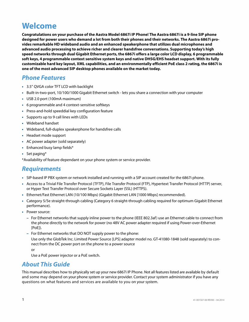
WelcomeCongratulations on your purchase of the Aastra Model 6867i IP Phone! The Aastra 6867i is a 9-line SIP phone designed for power users who demand a lot from both their phones and their networks. The Aastra 6867i pro-vides remarkable HD wideband audio and an enhanced speakerphone that utilizes dual microphones and advanced audio processing to achieve richer and clearer handsfree conversations. Supporting today’s high speed networks through dual Gigabit Ethernet ports, the 6867i offers a large color LCD display, 6 programmable soft keys, 4 programmable context sensitive system keys and native DHSG/EHS headset support. With its fully customizable hard key layout, XML capabilities, and an environmentally efficient PoE class 2 rating, the 6867i is one of the most advanced SIP desktop phones available on the market today.
Phone Features• 3.5” QVGA color TFT LCD with backlight
• Built-in-two-port, 10/100/1000 Gigabit Ethernet switch - lets you share a connection with your computer
• USB 2.0 port (100mA maximum)
• 6 programmable and 4 context-sensitive softkeys
• Press-and-hold speeddial key configuration feature
• Supports up to 9 call lines with LEDs
• Wideband handset
• Wideband, full-duplex speakerphone for handsfree calls
• Headset mode support
• AC power adapter (sold separately)
• Enhanced busy lamp fields*
• Set paging*
*Availability of feature dependant on your phone system or service provider.
Requirements• SIP-based IP PBX system or network installed and running with a SIP account created for the 6867i phone.
• Access to a Trivial File Transfer Protocol (TFTP), File Transfer Protocol (FTP), Hypertext Transfer Protocol (HTTP) server, or Hyper Text Transfer Protocol over Secure Sockets Layer (SSL) (HTTPS).
• Ethernet/Fast Ethernet LAN (10/100 Mbps) (Gigabit Ethernet LAN [1000 Mbps] recommended).
• Category 5/5e straight-through cabling (Category 6 straight-through cabling required for optimum Gigabit Ethernet performance).
• Power source:
– For Ethernet networks that supply inline power to the phone (IEEE 802.3af ) use an Ethernet cable to connect from the phone directly to the network for power (no 48V AC power adapter required if using Power-over-Ethernet [PoE]).
– For Ethernet networks that DO NOT supply power to the phone:Use only the GlobTek Inc. Limited Power Source [LPS] adapter model no. GT-41080-1848 (sold separately) to con-nect from the DC power port on the phone to a power sourceorUse a PoE power injector or a PoE switch.
About This GuideThis manual describes how to physically set up your new 6867i IP Phone. Not all features listed are available by default and some may depend on your phone system or service provider. Contact your system administrator if you have any questions on what features and services are available to you on your system.
1 41-001507-00 REV00 – 04.2014
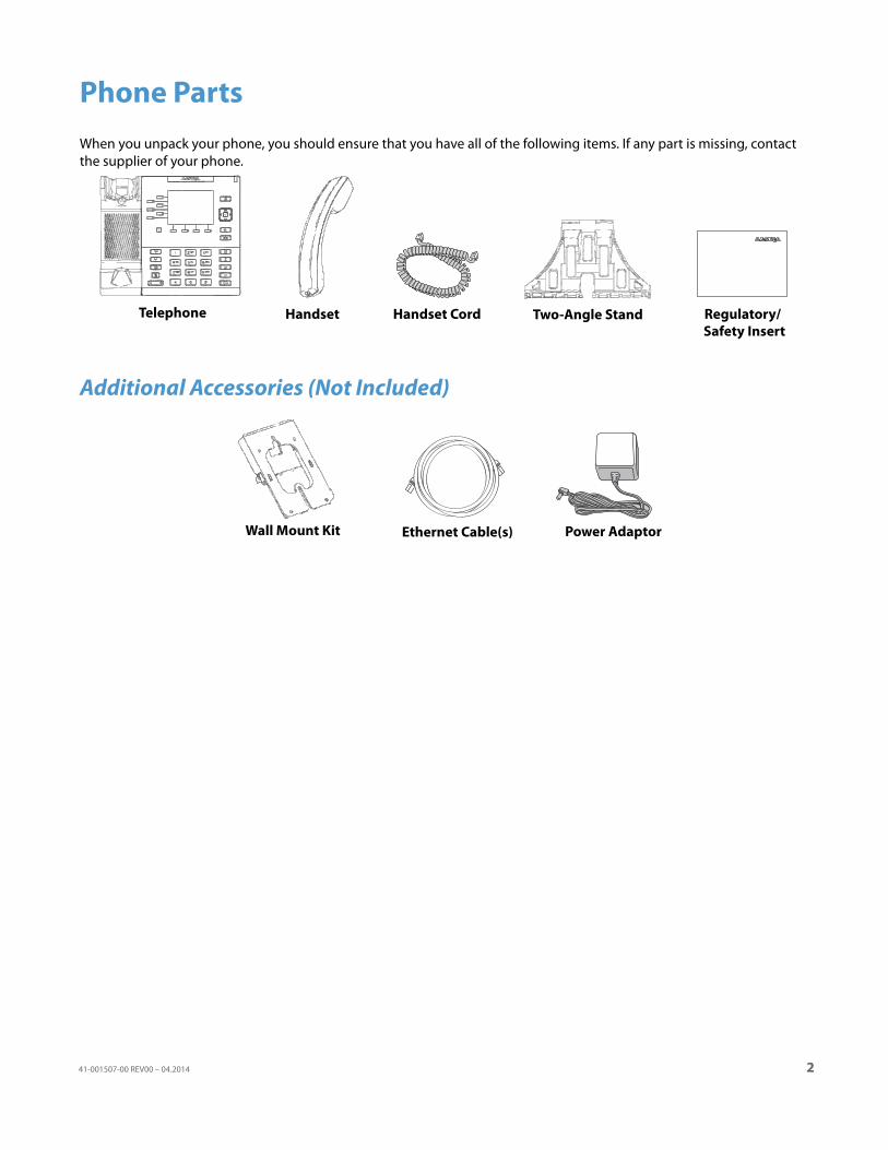
Phone PartsWhen you unpack your phone, you should ensure that you have all of the following items. If any part is missing, contact the supplier of your phone.
Additional Accessories (Not Included)
Telephone Handset Handset Cord Two-Angle Stand Regulatory/Safety Insert
Ethernet Cable(s) Power AdaptorWall Mount Kit
41-001507-00 REV00 – 04.2014 2
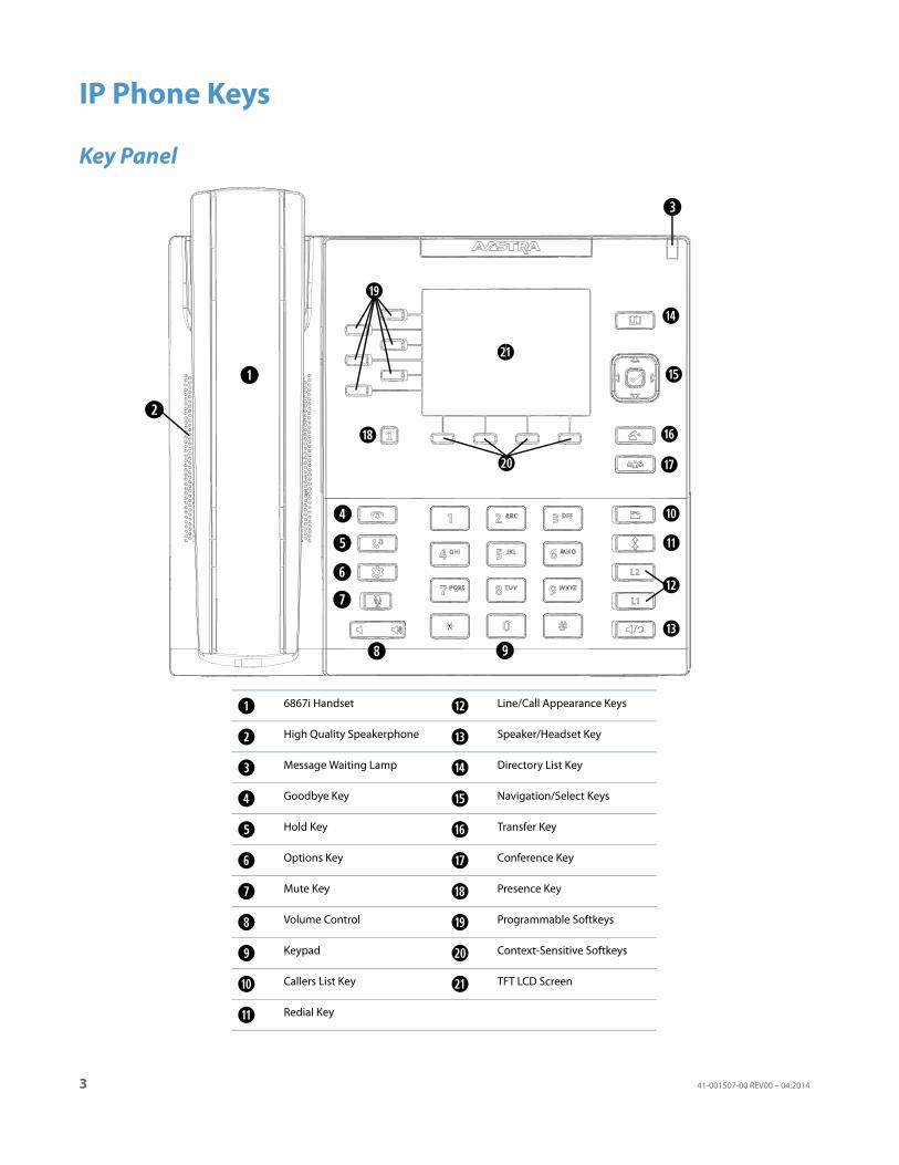
IP Phone Keys
Key Panel
6867i Handset Line/Call Appearance Keys
High Quality Speakerphone Speaker/Headset Key
Message Waiting Lamp Directory List Key
Goodbye Key Navigation/Select Keys
Hold Key Transfer Key
Options Key Conference Key
Mute Key Presence Key
Volume Control Programmable Softkeys
Keypad Context-Sensitive Softkeys
Callers List Key TFT LCD Screen
Redial Key
3 41-001507-00 REV00 – 04.2014
IP Phone Keys
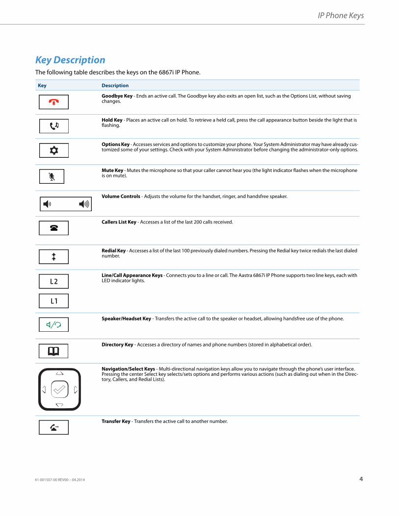
Key DescriptionThe following table describes the keys on the 6867i IP Phone.
Key Description
Goodbye Key - Ends an active call. The Goodbye key also exits an open list, such as the Options List, without saving changes.
Hold Key - Places an active call on hold. To retrieve a held call, press the call appearance button beside the light that is flashing.
Options Key - Accesses services and options to customize your phone. Your System Administrator may have already cus-tomized some of your settings. Check with your System Administrator before changing the administrator-only options.
Mute Key - Mutes the microphone so that your caller cannot hear you (the light indicator flashes when the microphone is on mute).
Volume Controls - Adjusts the volume for the handset, ringer, and handsfree speaker.
Callers List Key - Accesses a list of the last 200 calls received.
Redial Key - Accesses a list of the last 100 previously dialed numbers. Pressing the Redial key twice redials the last dialed number.
Line/Call Appearance Keys - Connects you to a line or call. The Aastra 6867i IP Phone supports two line keys, each with LED indicator lights.
Speaker/Headset Key - Transfers the active call to the speaker or headset, allowing handsfree use of the phone.
Directory Key - Accesses a directory of names and phone numbers (stored in alphabetical order).
Navigation/Select Keys - Multi-directional navigation keys allow you to navigate through the phone’s user interface. Pressing the center Select key selects/sets options and performs various actions (such as dialing out when in the Direc-tory, Callers, and Redial Lists).
Transfer Key - Transfers the active call to another number.
41-001507-00 REV00 – 04.2014 4
IP Phone Keys
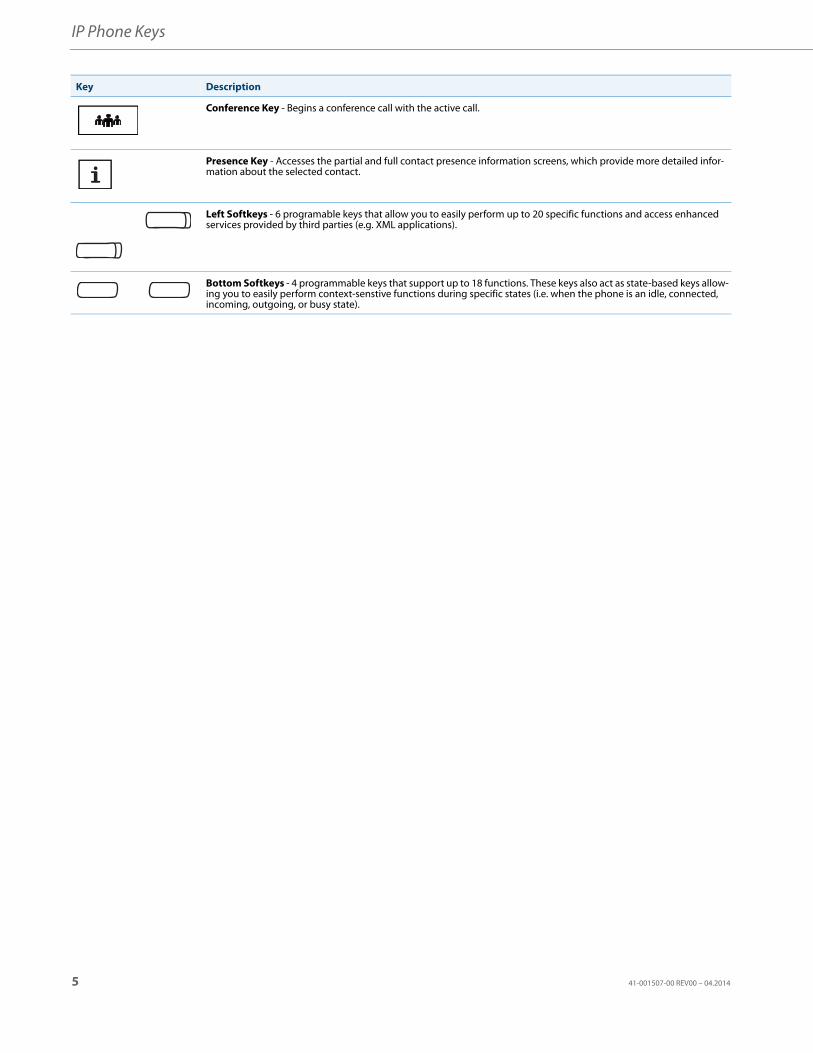
Conference Key - Begins a conference call with the active call.
Presence Key - Accesses the partial and full contact presence information screens, which provide more detailed infor-mation about the selected contact.
Left Softkeys - 6 programable keys that allow you to easily perform up to 20 specific functions and access enhanced services provided by third parties (e.g. XML applications).
Bottom Softkeys - 4 programmable keys that support up to 18 functions. These keys also act as state-based keys allow-ing you to easily perform context-senstive functions during specific states (i.e. when the phone is an idle, connected, incoming, outgoing, or busy state).
Key Description
5 41-001507-00 REV00 – 04.2014
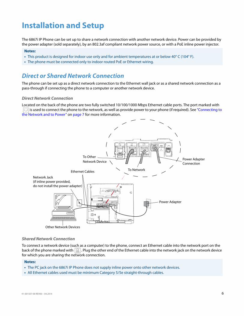
Installation and SetupThe 6867i IP Phone can be set up to share a network connection with another network device. Power can be provided by the power adapter (sold separately), by an 802.3af compliant network power source, or with a PoE inline power injector.
Direct or Shared Network ConnectionThe phone can be set up as a direct network connection to the Ethernet wall jack or as a shared network connection as a pass-through if connecting the phone to a computer or another network device.
Direct Network ConnectionLocated on the back of the phone are two fully switched 10/100/1000 Mbps Ethernet cable ports. The port marked with
is used to connect the phone to the network, as well as provide power to your phone (if required). See “Connecting to the Network and to Power” on page 7 for more information.
Shared Network Connection To connect a network device (such as a computer) to the phone, connect an Ethernet cable into the network port on the back of the phone marked with . Plug the other end of the Ethernet cable into the network jack on the network device for which you are sharing the network connection.
Notes:• This product is designed for indoor use only and for ambient temperatures at or below 40° C (104° F).• The phone must be connected only to indoor routed PoE or Ethernet wiring.
Notes:• The PC jack on the 6867i IP Phone does not supply inline power onto other network devices. • All Ethernet cables used must be minimum Category 5/5e straight-through cables.
To Other Network Device
To Network
Power AdapterConnection
Power Adapter
Ethernet Cables
Network Jack(if inline power provided,do not install the power adapter)
Other Network Devices
41-001507-00 REV00 – 04.2014 6
Installation and Setup
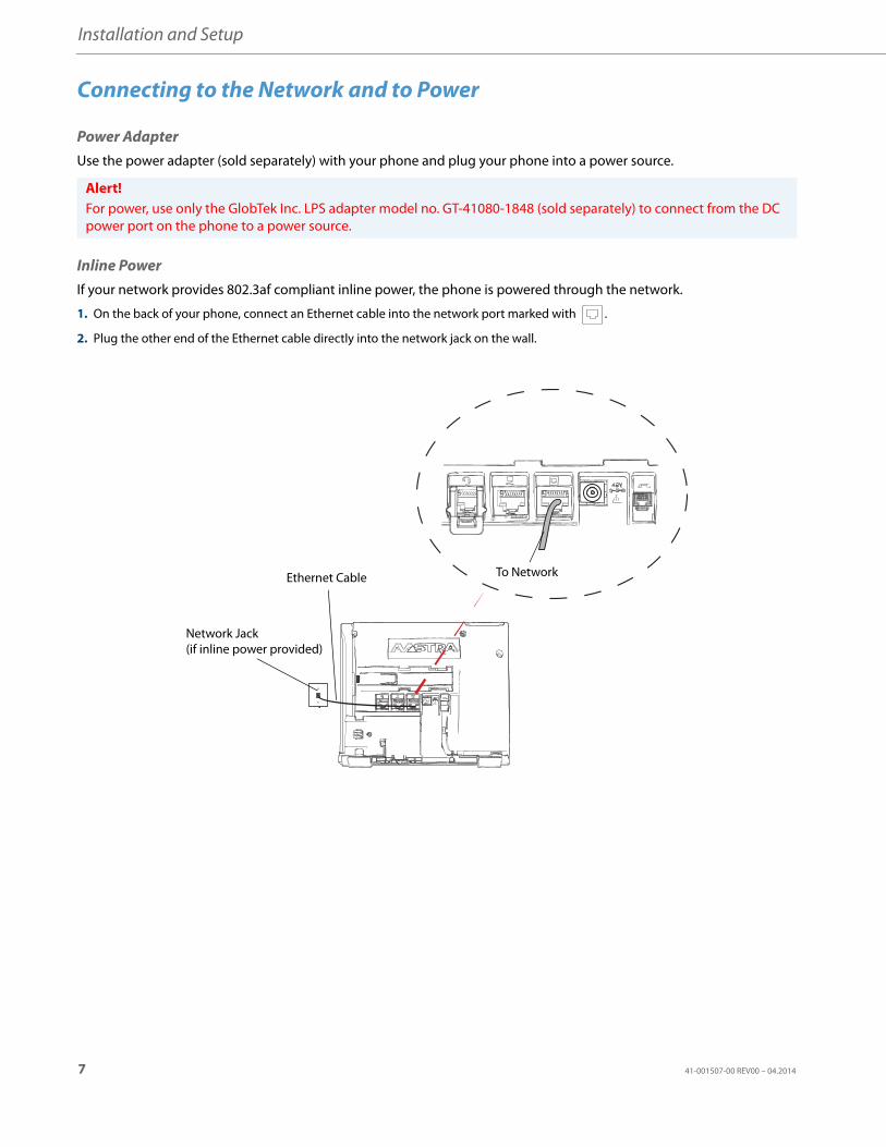
Connecting to the Network and to Power
Power AdapterUse the power adapter (sold separately) with your phone and plug your phone into a power source.
Inline PowerIf your network provides 802.3af compliant inline power, the phone is powered through the network.
Alert!For power, use only the GlobTek Inc. LPS adapter model no. GT-41080-1848 (sold separately) to connect from the DC power port on the phone to a power source.
1. On the back of your phone, connect an Ethernet cable into the network port marked with .
2. Plug the other end of the Ethernet cable directly into the network jack on the wall.
To NetworkEthernet Cable
Network Jack(if inline power provided)
7 41-001507-00 REV00 – 04.2014
Installation and Setup
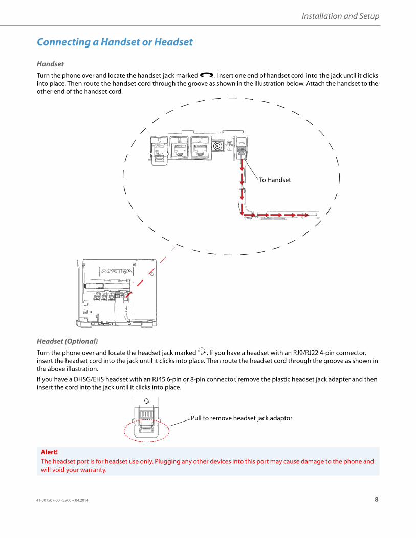
Connecting a Handset or Headset
HandsetTurn the phone over and locate the handset jack marked j. Insert one end of handset cord into the jack until it clicks into place. Then route the handset cord through the groove as shown in the illustration below. Attach the handset to the other end of the handset cord.
Headset (Optional)Turn the phone over and locate the headset jack marked f. If you have a headset with an RJ9/RJ22 4-pin connector, insert the headset cord into the jack until it clicks into place. Then route the headset cord through the groove as shown in the above illustration.
If you have a DHSG/EHS headset with an RJ45 6-pin or 8-pin connector, remove the plastic headset jack adapter and then insert the cord into the jack until it clicks into place.
Alert!The headset port is for headset use only. Plugging any other devices into this port may cause damage to the phone and will void your warranty.
To Handset
Pull to remove headset jack adaptor
41-001507-00 REV00 – 04.2014 8
Installation and Setup
Installation
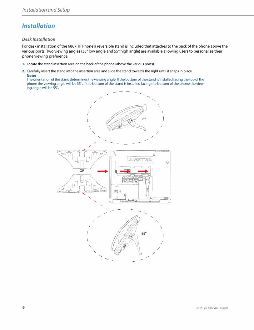
Desk InstallationFor desk installation of the 6867i IP Phone a reversible stand is included that attaches to the back of the phone above the various ports. Two viewing angles (35° low angle and 55° high angle) are available allowing users to personalize their phone viewing preference.
1. Locate the stand insertion area on the back of the phone (above the various ports).
2. Carefully insert the stand into the insertion area and slide the stand towards the right until it snaps in place. Note:The orientation of the stand determines the viewing angle. If the bottom of the stand is installed facing the top of the phone the viewing angle will be 35°. If the bottom of the stand is installed facing the bottom of the phone the view-ing angle will be 55°.
35°
55°
OR
9 41-001507-00 REV00 – 04.2014
Installation and Setup
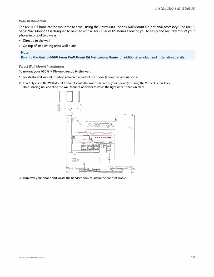
Wall InstallationThe 6867i IP Phone can be mounted to a wall using the Aastra 6800i Series Wall Mount Kit (optional accessory). The 6800i Series Wall Mount Kit is designed to be used with all 6800i Series IP Phones allowing you to easily and securely mount your phone in one of two ways:
• Directly to the wall
• On top of an existing telco wall plate
Direct Wall Mount InstallationTo mount your 6867i IP Phone directly to the wall:
Note:Refer to the Aastra 6800i Series Wall Mount Kit Installation Guide for additional product and installation details.
1. Locate the wall mount insertion area on the back of the phone (above the various ports).
2. Carefully insert the Wall Mount Connector into the insertion area of your phone (ensuring the Vertical Screw Lock Hole is facing up) and slide the Wall Mount Connector towards the right until it snaps in place.
3. Turn over your phone and locate the handset hook found in the handset cradle.
41-001507-00 REV00 – 04.2014 10
Installation and Setup
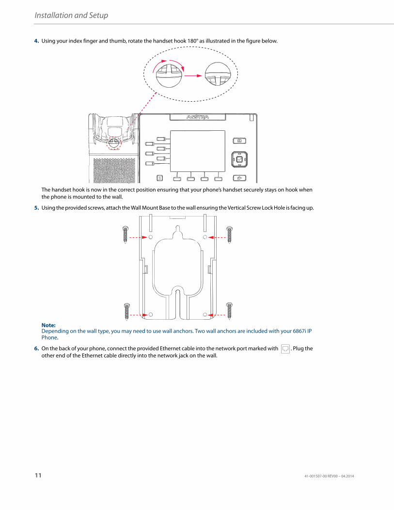
4. Using your index finger and thumb, rotate the handset hook 180° as illustrated in the figure below.
The handset hook is now in the correct position ensuring that your phone’s handset securely stays on hook when the phone is mounted to the wall.
5. Using the provided screws, attach the Wall Mount Base to the wall ensuring the Vertical Screw Lock Hole is facing up.
Note:Depending on the wall type, you may need to use wall anchors. Two wall anchors are included with your 6867i IP Phone.
6. On the back of your phone, connect the provided Ethernet cable into the network port marked with . Plug the other end of the Ethernet cable directly into the network jack on the wall.
11 41-001507-00 REV00 – 04.2014
Installation and Setup
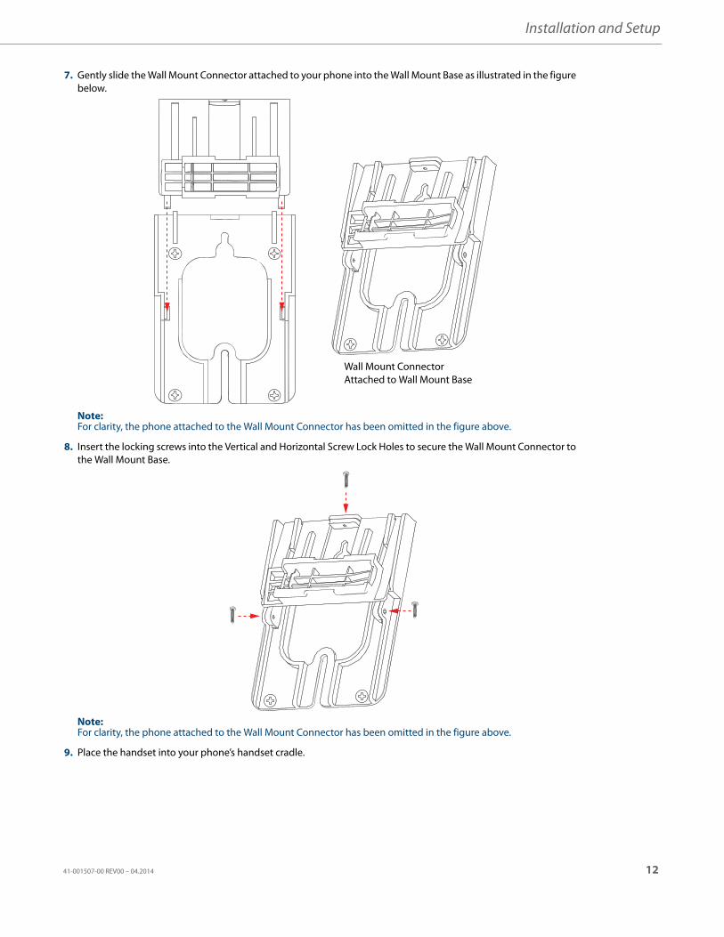
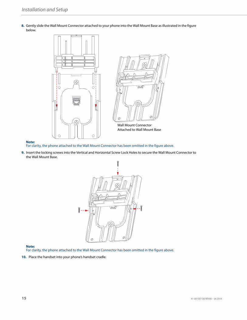
7. Gently slide the Wall Mount Connector attached to your phone into the Wall Mount Base as illustrated in the figure below.
Note:For clarity, the phone attached to the Wall Mount Connector has been omitted in the figure above.
8. Insert the locking screws into the Vertical and Horizontal Screw Lock Holes to secure the Wall Mount Connector to the Wall Mount Base.
Note:For clarity, the phone attached to the Wall Mount Connector has been omitted in the figure above.
9. Place the handset into your phone’s handset cradle.
Wall Mount ConnectorAttached to Wall Mount Base
41-001507-00 REV00 – 04.2014 12
Installation and Setup
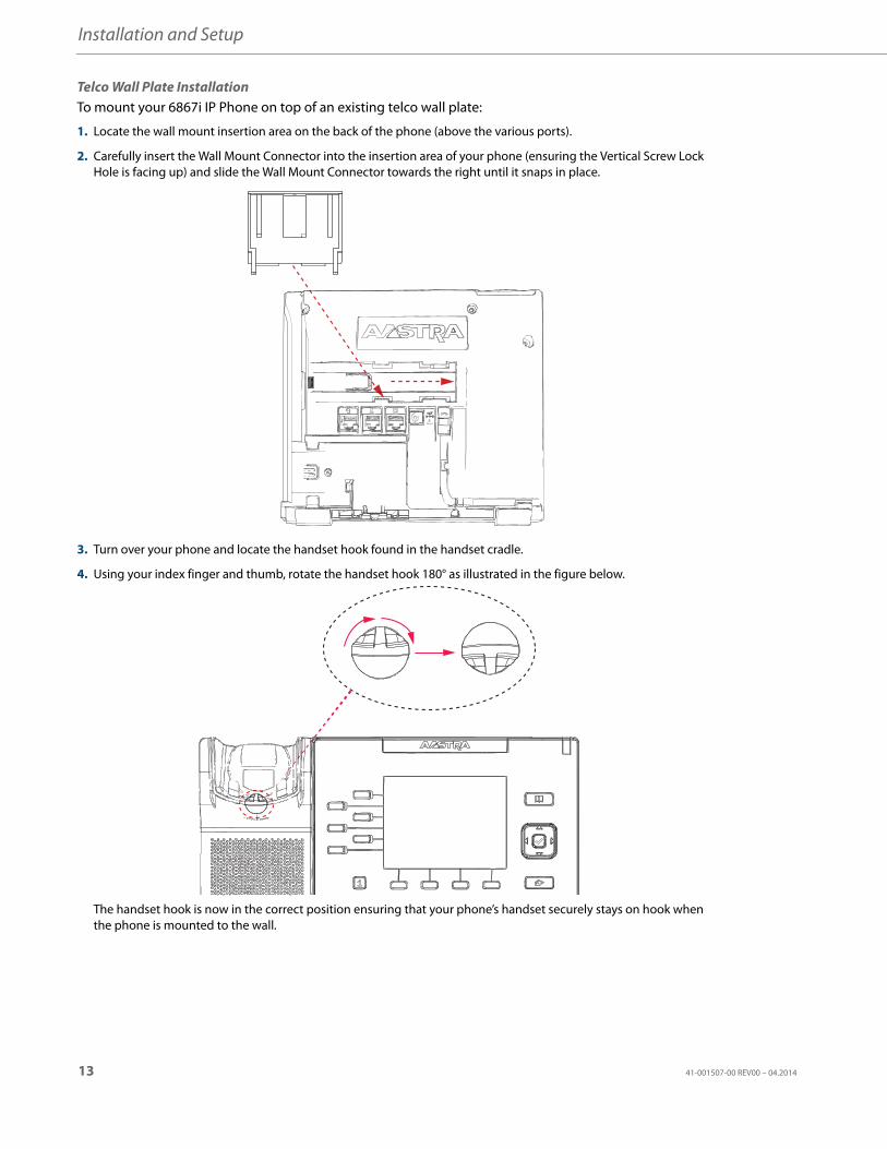
Telco Wall Plate InstallationTo mount your 6867i IP Phone on top of an existing telco wall plate:
1. Locate the wall mount insertion area on the back of the phone (above the various ports).
2. Carefully insert the Wall Mount Connector into the insertion area of your phone (ensuring the Vertical Screw Lock Hole is facing up) and slide the Wall Mount Connector towards the right until it snaps in place.
3. Turn over your phone and locate the handset hook found in the handset cradle.
4. Using your index finger and thumb, rotate the handset hook 180° as illustrated in the figure below.
The handset hook is now in the correct position ensuring that your phone’s handset securely stays on hook when the phone is mounted to the wall.
13 41-001507-00 REV00 – 04.2014
Installation and Setup
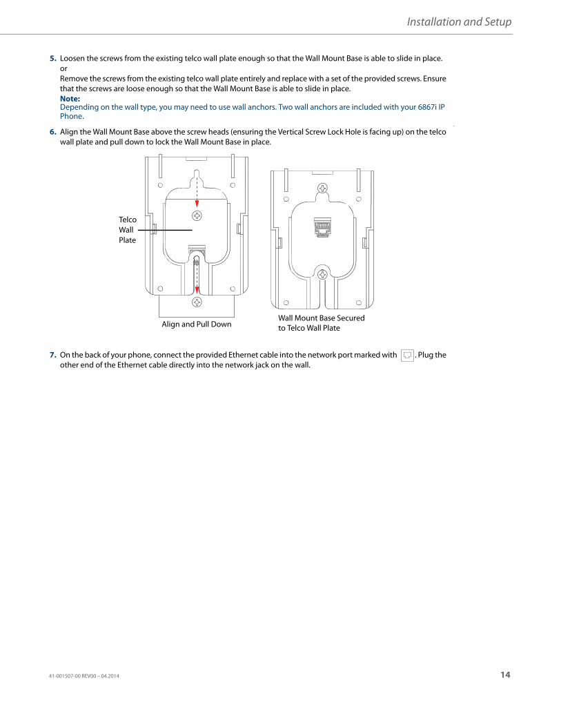
5. Loosen the screws from the existing telco wall plate enough so that the Wall Mount Base is able to slide in place.orRemove the screws from the existing telco wall plate entirely and replace with a set of the provided screws. Ensure that the screws are loose enough so that the Wall Mount Base is able to slide in place.Note:Depending on the wall type, you may need to use wall anchors. Two wall anchors are included with your 6867i IP Phone.
6. Align the Wall Mount Base above the screw heads (ensuring the Vertical Screw Lock Hole is facing up) on the telco wall plate and pull down to lock the Wall Mount Base in place.
v
7. On the back of your phone, connect the provided Ethernet cable into the network port marked with . Plug the other end of the Ethernet cable directly into the network jack on the wall.
Wall Mount Base Securedto Telco Wall PlateAlign and Pull Down
Telco Wall Plate
41-001507-00 REV00 – 04.2014 14
Installation and Setup
8. Gently slide the Wall Mount Connector attached to your phone into the Wall Mount Base as illustrated in the figure below.
Note:For clarity, the phone attached to the Wall Mount Connector has been omitted in the figure above.
9. Insert the locking screws into the Vertical and Horizontal Screw Lock Holes to secure the Wall Mount Connector to the Wall Mount Base.
Note:For clarity, the phone attached to the Wall Mount Connector has been omitted in the figure above.
10. Place the handset into your phone’s handset cradle.
Wall Mount ConnectorAttached to Wall Mount Base
15 41-001507-00 REV00 – 04.2014
Installation and Setup
Accessing Your Options via the Phone UI
Accessing Your Options via the Aastra Web UIYou can use the following procedure to access the phone options using the Aastra Web UI.
IP Phone UI
1. Press the Options key on the phone to enter the options list.
2. To go to an option, use the LEFT and RIGHT navigation keys to navigate through the main menus, and UP and DOWN navigation keys to navigate through the submenus.
3. Press the Select softkey or Select navigation key to enter the option’s respective menu screen.
4. Use the navigation keys to change a selected option (or keypad keys to enter information) and the press the Save softkey or Select navigation key to save your changes.
5. Press the Cancel softkey or the Goodbye key at any time to exit without saving changes.
Aastra Web UI
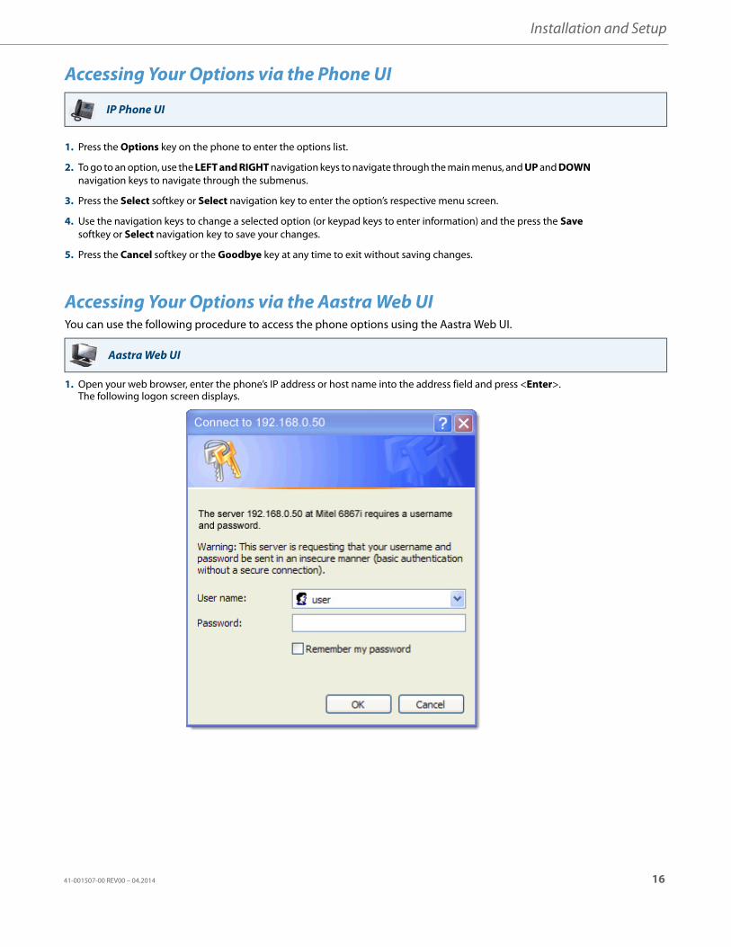
1. Open your web browser, enter the phone’s IP address or host name into the address field and press <Enter>.The following logon screen displays.
41-001507-00 REV00 – 04.2014 16
Installation and Setup
The side menu options that display in the Network Status window are dependant on whether you log in as an Adminis-trator or User. A longer list of options display in the side menu for an Administrator.
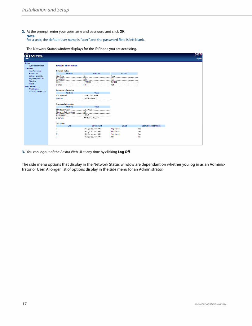
2. At the prompt, enter your username and password and click OK.Note:For a user, the default user name is “user” and the password field is left blank.
The Network Status window displays for the IP Phone you are accessing.
3. You can logout of the Aastra Web UI at any time by clicking Log Off.
17 41-001507-00 REV00 – 04.2014
Troubleshooting SolutionsWhy is the light not coming on with a new voice mail message?Your phone system or service provider must provide “visual” message waiting service for this function to work. Check with your system administrator for more information.
Why is my handset not working?Check to ensure that the handset cord is fully connected to both the phone and handset. See the section “Connecting a Handset or Headset” on page 8 for information.
Why is my display blank?Ensure that power is being provided to your phone. If your network does not provide inline power over Ethernet, you can obtain a PoE inline power injector to provide power over Ethernet locally to your phone. See the section “Connecting to the Network and to Power” on page 7 for details.
Why does the telephone wobble?Make sure the cords are routed properly through the back of the phone, as indicated in the section, “Connecting a Hand-set or Headset” on page 8. Check that the stand has been properly inserted.
What is a softkey?The 6867i has a total of 10 softkeys (6 programmable softkeys, located at the left of the front panel and 4 context-sensitive, state-based softkeys, located at the bottom of the front panel). You can program all 10 softkeys to perform specific func-tions and access enhanced services provided by third parties (for example, XML applications) on the phone.
41-001507-00 REV00 – 04.2014 18
Limited Warranty(Not applicable in Australia – see below for Limited Warranty in Australia)
Aastra warrants this product against defects and malfunctions in accordance with Aastra's authorized, written functional specification relating to such products during a one (1) year period from the date of original purchase (“Warranty Period”). If there is a defect or malfunction, Aastra shall, at its option, and as the exclusive remedy, either repair or replace the product at no charge, if returned within the Warranty Period. If replacement parts are used in making repairs, these parts may be refurbished, or may contain refurbished materials. If it is necessary to replace the product, it may be replaced with a refurbished product of the same design and color. If it should become necessary to repair or replace a defective or malfunctioning product under this warranty, the provisions of this warranty shall apply to the repaired or replaced product until the expiration of ninety (90) days from the date of pick up, or the date of shipment to you, of the repaired or replacement product, or until the end of the original Warranty Period, whichever is later. Proof of the original purchase date is to be provided with all products returned for warranty repairs.
ExclusionsAastra does not warrant its products to be compatible with the equipment of any particular telephone company. This warranty does not extend to damage to products resulting from improper installation or operation, alteration, accident, neglect, abuse, misuse, fire or natural causes such as storms or floods, after the product is in your possession. Aastra will not accept liability for any damages and/or long distance charges, which result from unauthorized and/or unlawful use.
Aastra shall not be liable for any incidental or consequential damages, including, but not limited to, loss, damage or expense directly or indirectly arising from the customer’s use of or inability to use this product, either separately or in combination with other equipment. This paragraph, however, shall not apply to consequential damages for injury to the person in the case of products used or bought for use primarily for personal, family or household purposes.
This warranty sets forth the entire liability and obligations of Aastra with respect to breach of warranty, and the warran-ties set forth or limited herein are the sole warranties and are in lieu of all other warranties, expressed or implied, includ-ing warranties or fitness for particular purpose and merchantability.
Warranty Repair ServicesShould the product fail during the Warranty Period;
• In North America, please call 1-800-574-1611 for further information.
• Outside North America, contact your sales representative for return instructions.
You will be responsible for shipping charges, if any. When you return this product for warranty service, you must present proof of purchase.
After Warranty ServiceAastra offers ongoing repair and support for this product. This service provides repair or replacement of your Aastra product, at Aastra's option, for a fixed charge. You are responsible for all shipping charges. For further information and shipping instructions:
• In North America, contact our service information number: 1-800-574-1611.
• Outside North America, contact your sales representative.
Note:Repairs to this product may be made only by the manufacturer and its authorized agents, or by others who are legally authorized. This restriction applies during and after the Warranty Period. Unauthorized repair will void the warranty.
19 41-001507-00 REV00 – 04.2014
Limited Warranty (Australia Only)The benefits under the Aastra Limited Warranty below are in addition to other rights and remedies to which you may be entitled under a law in relation to the products.
In addition to all rights and remedies to which you may be entitled under the Competition and Consumer Act 2010 (Com-monwealth) and any other relevant legislation, Aastra warrants this product against defects and malfunctions in accord-ance with Aastra's authorized, written functional specification relating to such products during a one (1) year period from the date of original purchase (“Warranty Period”). If there is a defect or malfunction, Aastra shall, at its option, and as the exclusive remedy under this limited warranty, either repair or replace the product at no charge, if returned within the War-ranty Period.
Repair Notice To the extent that the product contains user-generated data, you should be aware that repair of the goods may result in loss of the data. Goods presented for repair may be replaced by refurbished goods of the same type rather than being repaired. Refurbished parts may be used to repair the goods. If it is necessary to replace the product under this limited warranty, it may be replaced with a refurbished product of the same design and color.
If it should become necessary to repair or replace a defective or malfunctioning product under this warranty, the provi-sions of this warranty shall apply to the repaired or replaced product until the expiration of ninety (90) days from the date of pick up, or the date of shipment to you, of the repaired or replacement product, or until the end of the original Warranty Period, whichever is later. Proof of the original purchase date is to be provided with all products returned for warranty repairs.
ExclusionsAastra does not warrant its products to be compatible with the equipment of any particular telephone company. This war-ranty does not extend to damage to products resulting from improper installation or operation, alteration, accident, neglect, abuse, misuse, fire or natural causes such as storms or floods, after the product is in your possession. Aastra will not accept liability for any damages and/or long distance charges, which result from unauthorized and/or unlawful use.
To the extent permitted by law, Aastra shall not be liable for any incidental damages, including, but not limited to, loss, damage or expense directly or indirectly arising from your use of or inability to use this product, either separately or in combination with other equipment. This paragraph, however, is not intended to have the effect of excluding, restricting or modifying the application of all or any of the provisions of Part 5-4 of Schedule 2 to the Competition and Consumer Act 2010 (the ACL), the exercise of a right conferred by such a provision or any liability of Aastra in relation to a failure to com-ply with a guarantee that applies under Division 1 of Part 3-2 of the ACL to a supply of goods or services.
This express warranty sets forth the entire liability and obligations of Aastra with respect to breach of this express war-ranty and is in lieu of all other express or implied warranties other than those conferred by a law whose application cannot be excluded, restricted or modified. Our goods come with guarantees that cannot be excluded under the Australian Con-sumer Law. You are entitled to a replacement or refund for a major failure and for compensation for any other reasonably foreseeable loss or damage. You are also entitled to have the goods repaired or replaced if the goods fail to be of accepta-ble quality and the failure does not amount to a major failure.
41-001507-00 REV00 – 04.2014 20
Limited Warranty (Australia Only)
Warranty Repair ServicesProcedure: Should the product fail during the Warranty Period and you wish to make a claim under this express warranty, please contact the Aastra authorized reseller who sold you this product (details as per the invoice) and present proof of purchase. You will be responsible for shipping charges, if any.
Manufacturer: Aastra Telecom Australia Pty Ltd745 Springvale RoadMulgrave VIC 3170ABN 16 140 787 195Phone: +61 3 8562 2700
Limitation of Liability for Products not of a kind ordinarily acquired for personal, domestic or household use or consumption (e.g. goods/services ordinarily supplied for business-use) 1.1 To the extent permitted by law and subject to clause 1.2 below, the liability of Aastra to you for any non-compliance
with a statutory guarantee or loss or damage arising out of or in connection with the supply of goods or services (whether for tort (including negligence), statute, custom, law or on any other basis) is limited to:a) in the case of services:
i) the resupply of the services; orii) the payment of the cost of resupply; and
b) in the case of goods:i) the replacement of the goods or the supply of equivalent goods; orii) the repair of the goods; oriii) the payment of the cost of replacing the goods or of acquiring equivalent goods; or iv) the payment of the cost of having the goods repaired.
1.2 Clause 1.1 is not intended to have the effect of excluding, restricting or modifying:a) the application of all or any of the provisions of Part 5-4 of Schedule 2 to the Competition and Consumer Act 2010
(the ACL); orb) the exercise of a right conferred by such a provision; orc) any liability of Aastra in relation to a failure to comply with a guarantee that applies under Division 1 of Part 3-2
of the ACL to a supply of goods or services.
After Warranty ServiceAastra offers ongoing repair and support for this product. If you are not otherwise entitled to a remedy for a failure to comply with a guarantee that cannot be excluded under the Australian Consumer Law, this service provides repair or replacement of your Aastra product, at Aastra's option, for a fixed charge. You are responsible for all shipping charges. For further information and shipping instructions contact:
Aastra Telecom Australia Pty Ltd745 Springvale RoadMulgrave VIC 3170ABN 16 140 787 195Phone: +61 3 8562 2700
Note:Repairs to this product may be made only by the manufacturer and its authorized agents, or by others who are legally authorized. Unauthorized repair will void this express warranty.
21 41-001507-00 REV00 – 04.2014
Disclaimer
Aastra will not accept liability for any damages and/or long distance charges, which result from unauthorized and/or unlawful use. While every effort has been made to ensure accuracy, Aastra will not be liable for technical or editorial errors or omissions contained within this documentation. The information contained in this documentation is subject to change without notice.
Copyright © 2014 Mitel Networks Corporation, www.aastra.com.