Embed Size (px)
Citation preview
By Authority OfTHE UNITED STATES OF AMERICA
Legally Binding Document
By the Authority Vested By Part 5 of the United States Code § 552(a) and Part 1 of the Code of Regulations § 51 the attached document has been duly INCORPORATED BY REFERENCE and shall be considered legally binding upon all citizens and residents of the United States of America. HEED THIS NOTICE: Criminal penalties may apply for noncompliance.
Official Incorporator:THE EXECUTIVE DIRECTOROFFICE OF THE FEDERAL REGISTERWASHINGTON, D.C.
Document Name:
CFR Section(s):
Standards Body:
e
American Society for Testing and Materials
49 CFR 192.113
ASTM A106: Standard Specification for SeamlessCarbon Steel Pipe for High-Temperature Service

a Designation: A 106/A 106M - 04b ~U .. 1
INTERNATIONAL
Standard Specification for
Used in USDOE·NE standards
Seamless Carbon Steel Pipe for High-Temperature Service1
This standard is issued under the fixed designation A 1061 A 106M; the number immediately following the designation indicates the year of original adoption or, in the case of revision, the year of last revision. A number in parentheses indicates the year of last reapproval. A superscript epsilon (e) indicates an editorial change since the last revision or reapproval.
This standard has been approved for use by agencies of the Department of Defense.
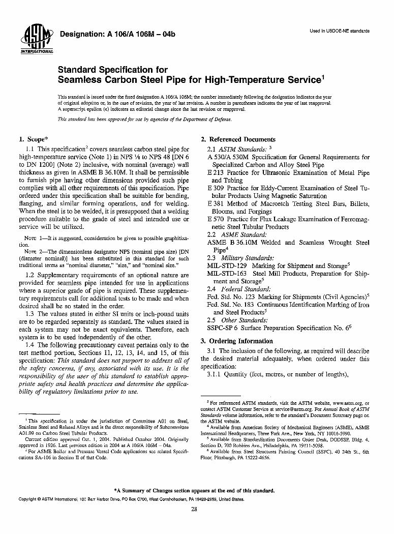
1. Scope*
1.1 This specification2 covers seamless carbon steel pipe for high-temperature service (Note 1) in NPS Vs to NPS 48 [DN 6 to DN 1200] (Note 2) inclusive, with nominal (average) wall thickness as given in ASME B 36.lOM. It shall be permissible to furnish pipe having other dimensions provided such pipe complies with all other requirements of this specification. Pipe ordered under this specification shall be suitable for bending, flanging, and similar forming operations, and for welding. When the steel is to be welded, it is presupposed that a welding procedure suitable to the grade of steel and intended use or service will be utilized.
NOTE I-It is suggested, consideration be given to possible graphitiza· tion.
NOTE 2-The dimensionless designator NPS (nominal pipe size) [DN (diameter nominal)] has been substituted in this standard for such traditional terms as "nominal diameter," "size," and "nominal size."
1.2 Supplementary requirements of an optional nature are provided for seamless pipe intended for use in applications where a superior grade of pipe is required. These supplementary requirements call for additional tests to be made and when desired shall be so stated in the order.
1.3 The values stated in either SI units or inch-pound units are to be regarded separately as standard. The values stated in each system may not be exact equivalents. Therefore, each system is to be used independently of the other.
1.4 The following precautionary caveat pertains only to the test method portion, Sections 11, 12, 13, 14, and 15, of this specification: This standard does not purport to address all of the safety concerns, if any, associated with its use. It is the responsibility of the user of this standard to establish appropriate safety and health practices and determine the applicability of regulatory limitations prior to use.
1 This specification is under the jurisdiction of Committee AOI on Steel, Stainless Steel and Related Alloys and is the direct responsibility of Subcommittee AOl.09 on Carbon Steel Tubular Products.
Current edition approved Oct. I, 2004. Published October 2004. Originally approved in 1926. Last previous edition in 2004 as A 1061 A 106M - 04a.
2 For ASME Boiler and Pressure Vessel Code applications see related Specifi· cations SA-106 in Section II of that Code.
2. Referenced Documents
2.1 ASTM Standards: 3
A 530lA 530M Specification for General Requirements for Specialized Carbon and Alloy Steel Pipe
E 213 Practice for Ultrasonic Examination of Metal Pipe and Tubing
E 309 Practice for Eddy-Current Examination of Steel Tubular Products Using Magnetic Saturation
E 381 Method of Macroetch Testing Steel Bars, Billets, Blooms, and Forgings
E 570 Practice for Flux Leakage Examination of Ferromagnetic Steel Tubular Products
2.2 ASME Standard: ASME B 36.lOM Welded and Seamless Wrought Steel
Pipe4
2.3 Military Standards: MIL-STD-129 Marking for Shipment and Storage5
MIL-STD-163 Steel Mill Products, Preparation for Ship-ment and Storage5
2.4 Federal Standard: Fed. Std. No. 123 Marking for Shipments (Civil Agencies)5 Fed. Std. No. 183 Continuous Identification Marking ofIron
and Steel Products5
2.5 Other Standards: SSPC-SP 6 Surface Preparation Specification No. 66
3. Ordering Information
3.1 The inclusion of the following, as required will describe the desired material adequately, when ordered under this specification:
3.1.1 Quantity (feet, metres, or number oflengths),
3 For referenced ASTM standards, visit the ASTM website, www.astm.org, or contact ASTM Customer Service at [email protected]. For Annual Book of ASTM Standards volume information, refer to the standard's Document Summary page on the ASTM website.
4 Available from American Society of Mechanical Engineers (ASME), ASME International Headquarters, Three Park Ave., New York, NY 10016·5990.
5 Available from Standardization Documents Order Desk, DODSSP, Bldg. 4, Section D, 700 Robbins Ave., Philadelphia, PA 19IIl·5098.
6 Available from Steel Structures Painting Council (SSPC), 40 24th St., 6th Floor, Pittsburgh, PA 15222-4656.
* A Summary of Changes section appears at the end of this standard.
Copyright © ASTM International, 100 Barr Harbor Drive, PO Box C700, West Conshohocken, PA 19428·2959, United States.
28
~ A 106/A 106M - 04b
3.1.2 Name of material (seamless carbon steel pipe), 3.1.3 Grade (Table 1), 3.1.4 Manufacture (hot-finished or cold-drawn), 3.1.5 Size (NPS [DN] and weight class or schedule number,
or both; outside diameter and nominal wall thickness; or inside diameter and nominal wall thickness),
3.1.6 Special outside diameter tolerance pipe (16.2.2), 3.1.7 Inside diameter tolerance pipe, over 10 in. [250 mm]
ID (16.2.3), 3.1.8 Length (specific or random, Section 20), 3.1.9 Optional requirements (Section 9 and Sl to S8), 3.1.1 0 Test report required (Section on Certification of
Specification A 530/ A 530M), 3.1.11 Specification designation (A 106 or A 106M, includ
ing year-date), 3.1.12 End use of material, 3.1.13 Hydrostatic test in accordance with Specification
A 530lA 530M or 13.3 of this specification, or NDE in accordance with Section 14 of this specification.
3.1.14 Special requirements.
4. Process
4.1 The steel shall be killed steel, with the primary melting process being open-hearth, basic-oxygen, or electric-furnace, possibly combined with separate degassing or refining. If secondary melting, using electroslag remelting or vacuum-arc remelting is subsequently employed, the heat shall be defined as all of the ingots remelted from a single primary heat.
4.2 Steel cast in ingots or strand cast is permissible. When steels of different grades are sequentially strand cast, identification of the resultant transition material is required. The producer shall remove the transition material by any established procedure that positively separates the grades.
4.3 For pipe NPS 1 V2 [DN 40] and under, it shall be permissible to furnish hot finished or cold drawn.
4.4 Unless otherwise specified, pipe NPS 2 [DN 50] and over shall be furnished hot finished. When agreed upon between the manufacturer and the purchaser, it is permissible to furnish cold-drawn pipe.
5. Heat Treatment
5.1 Hot-finished pipe need not be heat treated. Cold-drawn pipe shall be heat treated after the final cold draw pass at a temperature of 1200 of (650°C) or higher.
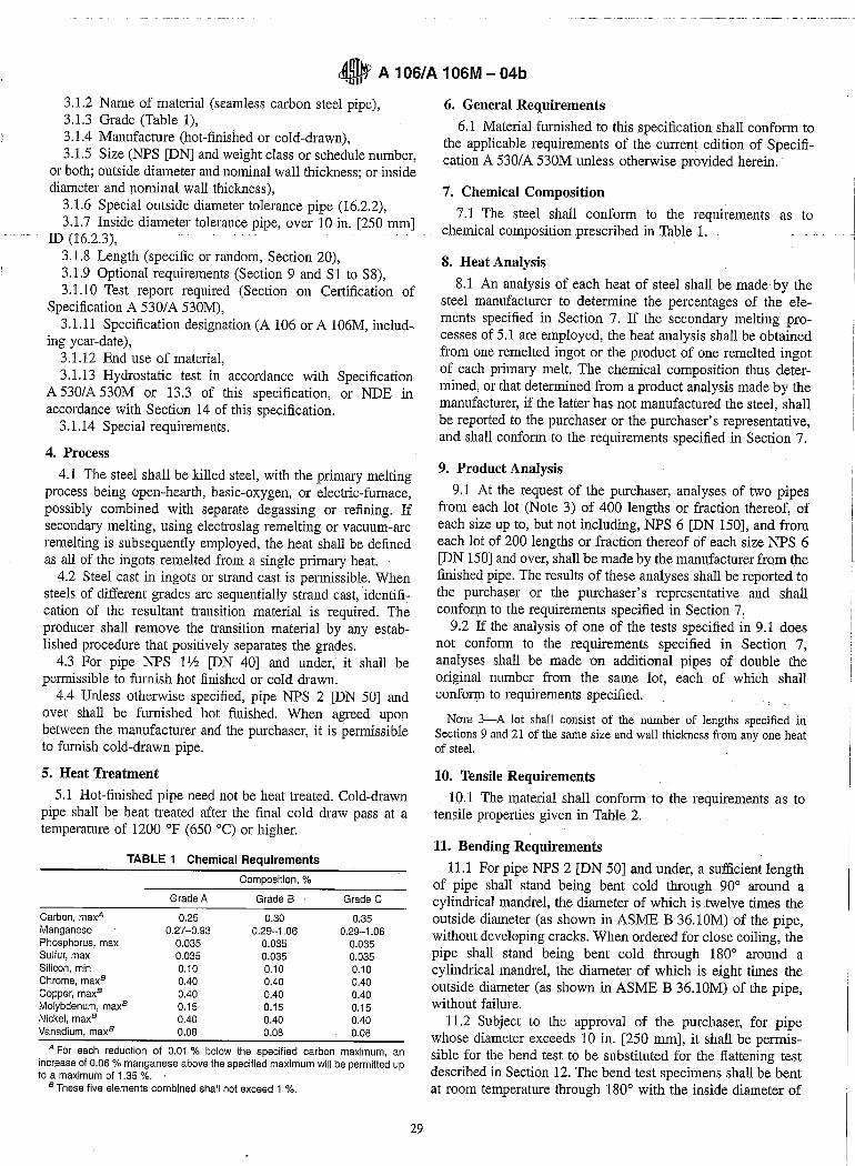
TABLE 1 Chemical Requirements
Composition, %
Grade A Grade B Grade C
Carbon, maxA 0.25 0.30 0.35 Manganese 0.27-0.93 0.29-1.06 0.29-1.06 Phosphorus, max 0.035 0.035 0.035 Sulfur, max 0.035 0.035 0.035 Silicon, min 0.10 0.10 0.10 Chrome, maxB 0.40 0.40 0.40 Copper, maxB 0.40 0.40 0.40 Molybdenum, maxB 0.15 0.15 0.15 Nickel, maxB 0.40 0.40 0.40 Vanadium, maxB 0.08 0.08 0.08
A For each reduction of 0.01 % below the specified carbon maximum, an increase of 0.06 % manganese above the specified maximum will be permitted up to a maximum of 1.35 %. '
B These five elements combined shall not exceed 1 %.
29
6. General Requirements
6.1 Material furnished to this specification shall conform to the applicable requirements of the current edition of Specification A 530/ A 530M unless otherwise provided herein.
7. Chemical Composition
7.1 The steel shall conform to the requirements as to chemical composition prescribed in Table 1.
8. Heat Analysis
8.1 An analysis of each heat of steel shall be made by the steel manufacturer to determine the percentages of the elements specified in Section 7. If the secondary melting processes of 5.1 are employed, the heat analysis shall be obtained from one remelted ingot or the product of one remelted ingot of each primary melt. The chemical composition thus determined, or that determined from a product analysis made by the manufacturer, if the latter has not manufactured the steel, shall be reported to the purchaser or the purchaser's representative, and shall conform to the requirements specified in Section 7.
9. Product Analysis
9.1 At the request of the purchaser, analyses of two pipes from each lot (Note 3) of 400 lengths or fraction thereof, of each size up to, but not including, NPS 6 [DN 150], and from each lot of 200 lengths or fraction thereof of each size NPS 6 [DN 150] and over, shall be made by the manufacturer from the finished pipe. The results of these analyses shall be reported to the purchaser or the purchaser's representative and shall conform to the requirements specified in Section 7:
9.2 If the analysis of one of the tests specified in 9.1 does not conform to the requirements specified in Section 7, analyses shall be made on additional pipes of double the original number from the same lot, each of which shall conform to requirements specified.
NOTE 3-A lot shall consist of the number of lengths specified in Sections 9 and 21 of the same size and wall thickness from anyone heat of steel.
10. Tensile Requirements
10.1 The material shall conform to the requirements as to tensile properties given in Table 2.
11. Bending Requirements
11.1 For pipe NPS 2 [DN 50] and under, a sufficient length of pipe shall stand being bent cold through 90° around a cylindrical mandrel, the diameter of which is twelve times the outside diameter (as shown in ASME B36.lOM) of the pipe, without developing cracks. When ordered for close coiling, the pipe shall stand being bent cold through 180° around a cylindrical mandrel, the diameter of which is eight times the outside diameter (as shown in ASME B 36.lOM) of the pipe, without failure.
11.2 Subject to the approval of the purchaser, for pipe whose diameter exceeds 10 in. [250 mm], it shall be permissible for the bend test to be substituted for the flattening test described in Section 12. The bend test specimens shall be bent at room temperature through 180° with the inside diameter of
o A 106/A 106M - 04b
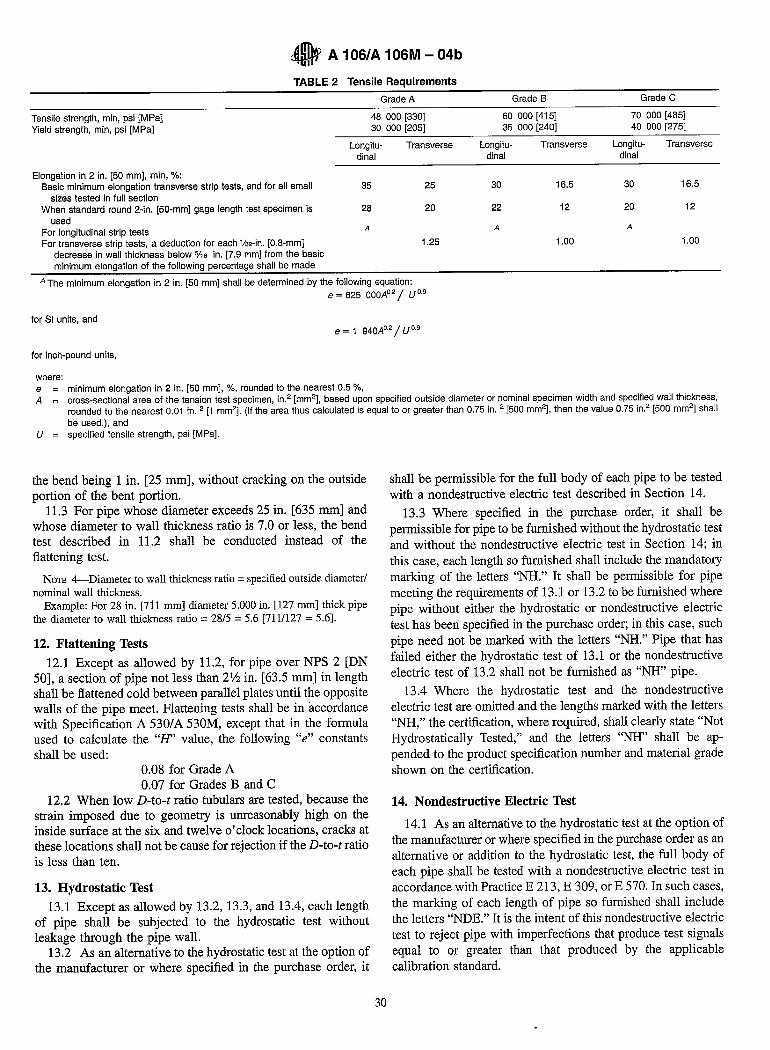
TABLE 2 Tensile Requirements
Grade A Grade B Grade C
Tensile strength, min, psi [MPa] Yield strength, min, psi [MPa]
48 000 [330] 30 000 [205]
60 000 [415] 70 000 [485] 35 000 [240] 40 000 [275]
Elongation in 2 in. [50 mm], min, 'Yo: Basic minimum elongation transverse strip tests, and for all small
sizes tested in full section When standard round 2-in. [50-mm] gage length test specimen is
used For longitudinal strip tests For transverse strip tests, a deduction for each Vs2-in. [0.8-mm]
decrease in wall thickness below 5/,6 in. [7.9 mm] from the basic minimum elongation of the following percentage shall be made
Longitudinal
35
28
A
Transverse Longitu-dinal
25 30
20 22
A
1.25
Transverse Longitu- Transverse dinal
16.5 30 16.5
12 20 12
A
1.00 1.00
A The minimum elongation in 2 in. [50 mm] shall be determined by the following equation: e = 625 000A0 2 / U 0.9
for 81 units, and e = 1 940Ao.2 / U 0.9
for inch-pound units,
where: e minimum elongation in 2 in. [50 mm], %, rounded to the nearest 0.5 %, A cross-sectional area of the tension test specimen, in.2 [mm2], based upon specified outside diameter or nominal specimen width and specified wall thickness,
rounded to the nearest 0.01 in. 2 [1 mm2]. (If the area thus calculated is equal to or greater than 0.75 in. 2 [500 mm2], then the value 0.75 in.2 [500 mm2] shall be used.), and
U specified tensile strength, psi [MPa].
the bend being 1 in. [25 mm], without cracking on the outside portion of the bent portion.
11.3 For pipe whose diameter exceeds 25 in. [635 mm] and whose diameter to wall thickness ratio is 7.0 or less, the bend test described in 11.2 shall be conducted instead of the flattening test.
NOTE 4--Diameter to wall thickness ratio = specified outside diameter/ nominal wall thickness.
Example: For 28 in. [711 mm] diameter 5.000 in. [127 mm] thick pipe the diameter to wall thickness ratio = 28/5 = 5.6 [711/127 = 5.6].
12. Flattening Tests
12.1 Except as allowed by 11.2, for pipe over NPS 2 [DN 50], a section of pipe not less than 21/2 in. [63.5 mm] in length shall be flattened cold between parallel plates until the opposite walls of the pipe meet. Flattening tests shall be in accordance with Specification A 530/ A 530M, except that in the formula used to calculate the "H' value, the following "e" constants shall be used:
0.08 for Grade A 0.07 for Grades B and C
12.2 When low D-to-t ratio tubulars are tested, because the strain imposed due to geometry is unreasonably high on the inside surface at the six and twelve o'clock locations, cracks at these locations shall not be cause for rejection if the D-to-t ratio is less than ten.
13. Hydrostatic Test
13.1 Except as allowed by 13.2, 13.3, and 13.4, each length of pipe shall be subjected to the hydrostatic test without leakage through the pipe wall.
13.2 As an alternative to the hydrostatic test at the option of the manufacturer or where specified in the purchase order, it
30
shall be permissible for the full body of each pipe to be tested with a nondestructive electric test described in Sectien 14.
13.3 Where specified in the purchase order, it shall be permissible for pipe to be furnished without the hydrostatic test and without the nondestructive electric test in Section 14; in this case, each length so furnished shall include the mandatory marking of the letters "NH." It shall be permissible for pipe meeting the requirements of 13.1 or 13.2 to be furnished where pipe without either the hydrostatic or nondestructive electric test has been specified in the purchase order; in this case, such pipe need not be marked with the letters "NH." Pipe that has failed either the hydrostatic test of 13.1 or the nondestructive electric test of 13.2 shall not be furnished as "NH" pipe.
13.4 Where the hydrostatic test and the nondestructive electric test are omitted and the lengths marked with the letters "NH," the certification, where required, shall clearly state "Not Hydrostatically Tested," and the letters "NH" shall be appended to the product specification number and material grade shown on the certification.
14. Nondestructive Electric Test
14.1 As an alternative to the hydrostatic test at the option of the manufacturer or where specified in the purchase order as an alternative or addition to the hydrostatic test, the full body of each pipe shall be tested with a nondestructive electric test in accordance with Practice E 213, E 309, or E 570. In such cases, the marking of each length of pipe so furnished shall include the letters "NDE." It is the intent of this nondestructive electric test to reject pipe with impelfections that produce test signals equal to or greater than that produced by the applicable calibration standard.
1 !
\ \ .I
)
cO A 106/A 106M - 04b
14.2 Where the nondestructive electric test is peIiormed, the lengths shall be marked with the letters "NDE." The certification, where required, shall state "Nondestructive Electric Tested" and shall indicate which of the tests was applied. Also, the letters "NDE" shall be appended to the product specification number and material grade shown on the certification.
14.3 The following information is for the benefit of the user of this specification:
14.3.1 The reference standards defined in 14.4 through 14.6 are convenient standards for calibration of nondestructive testing equipment. The dimensions of such standards are not to be construed as the minimum sizes of impeIiections detectable by such equipment.
14.3.2 The ultrasonic testing referred to in this specification is capable of detecting the presence and location of significant longitudinally or circumferentially oriented imperfections: however, different techniques need to be employed for the detection of such differently oriented impeIiections. Ultrasonic testing is not necessarily capable of detecting short, deep imperfections.
14.3.3 The eddy current examination referenced in this specification has the capability of detecting significant imperfections, especially of the short abrupt type.
14.3.4 The flux leakage examination referred to in this specification is capable of detecting the presence and location of significant longitudinally or transversely oriented impeIiections: however, different techniques need to be employed for the detection of such differently oriented impeIiections.
14.3.5 The hydrostatic test referred to in Section 13 has the capability of finding defects of a size permitting the test fluid to leak through the tube wall and may be either visually seen or detected by a loss of pressure. Hydrostatic testing is not necessarily capable of detecting very tight, through-the-wall impeIiections or impeIiections that extend an appreciable distance into the wall without complete penetration.
14.3.6 A purchaser interested in ascertaining the nature (type, size, location, and orientation) of discontinuities that can be detected in the specific applications of these examinations is directed to discuss this with the manufacturer of the tubular product.
14.4 For ultrasonic testing, the calibration reference notches shall be, at the option of the producer, anyone of the three common notch shapes shown in Practice E 213. The depth of notch shall not exceed 12V2 % of the specified wall thickness of the pipe or 0.004 in. [0.1 mm], whichever is greater.
14.5 For eddy current testing, the calibration pipe shall contain, at the option of the producer, anyone of the following discontinuities to establish a minimum. sensitivity level for rejection:
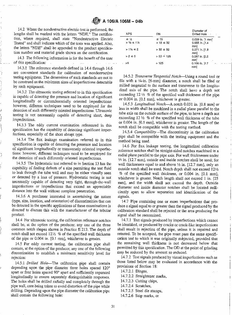
14.5.1 Drilled Hole-The calibration pipe shall contain depending upon the pipe diameter three holes spaced 120° apart or four holes spaced 90° apart and sufficiently separated longitudinally to ensure separately distinguishable responses. The holes shall be drilled radially and completely through the pipe wall, care being taken to avoid distortion of the pipe while drilling. Depending upon the pipe diameter the calibration pipe shall contain the following hole:
31
Diameter of NPS DN Drilled Hole
:5% :5 15 0.039 in. [1 mmJ >V2:51% >15:532 0.055 in. [1.4
mmJ >1%:52 > 32 :5 50 0.071 in. [1.8
mmJ >2:55 > 50 :5 125 0.087 in. [2.2
mmJ >5 > 125 0.106 in. [2.7
mmJ
14.5.2 Transverse Tangential Notch-Using a round tool or file with a V4-in. [6-mm] diameter, a notch shall be filed or milled tangential to the surface and transverse to the longitudinal axis of the pipe. The notch shall have· a depth not exceeding 12 112 % of the specified wall thickness of the pipe or 0.004 in. [0.1 mm], whichever is greater.
14.5.3 Longitudinal Notch-A notch 0.031 in. [0.8 mm] or less in width shall be machined in a radial plane parallel to the tube axis on the outside suIiace of the pipe, to have a depth not exceeding 12 112 % of the specified wall thickness of the tube or 0.004 in. [0.1 mm], whichever is greater. The length of the notch shall be compatible with the testing method.
14.5.4 Compatibility-The discontinuity in the calibration pipe shall be compatible with the testing equipment and the method being used.
14.6 For flux leakage testing, the longitudinal calibration reference notches shall be straight-sided notches machined in a radial plane parallel to the pipe axis. For wall thicknesses under V2 in. [12.7 mm], outside and inside notches shall be used; for wall thicknesses equal to and above V2 in. [12.7 mm], only an outside notch shall be used. Notch depth shall not exceed 121/2 % of the specified wall thickness, or 0.004 in. [0.1 mm],
whichever is greater. Notch length shall not exceed 1 in. [25 mm], and the width shall not exceed the depth. Outside diameter and inside diameter notches shall be located sufficiently apart to allow separation and identification of the signals.
14.7 Pipe containing one or more impeIiections that produce a signal equal to or greater than the signal produced by the calibration standard shall be rejected or the area producing the signal shall be reexamined.
14.7.1 Test signals produced by impeIiections which cannot be identified, or produced by cracks or crack-like impeIiections shall result in rejection of the pipe, unless it is repaired and retested. To be accepted, the pipe must pass the same specification test to which it was originally subjected, provided that the remaining wall thickness is not decreased below that permitted by this specification. The OD at the point of grinding may be reduced by the amount so reduced.
14.7.2 Test signals produced by visual impeIiections such as those listed below may be evaluated in accordance with the provisions of Section 18:
14.7.2.1 Dinges, 14.7.2.2 Straightener marks, 14.7.2.3 Cutting chips, 14.7.2.4 Scratches, 14.7.2.5 Steel die stamps, 14.7.2.6 Stop marks, or
~ A 10S/A 10SM - 04b
14.7.2.7 Pipe reducer ripple. 14.8 The test methods described in this section are not
necessarily capable of inspecting the end portion of pipes, a condition referred to as "end effect." The length of such end effect shall be determined by the manufacturer and, when specified in the purchase order, reported to the purchaser.
15. Nipples
15.1 Nipples shall be cut from pipe of the same dimensions and quality described in this specification.
16. Dimensions, Mass, and Permissible Variations
16.1 Mass-The mass of any length of pipe shall not vary more than 10 % over and 3.5 % under that specified. Unless otherwise agreed upon between the manufacturer and the purchaser, pipe in NPS 4 [DN 100] and smaller may be weighed in convenient lots; pipe larger than NPS 4 [DN 100] shall be weighed separately.
16.2 Diameter-The tolerances for diameter shall be in accordance with the following:
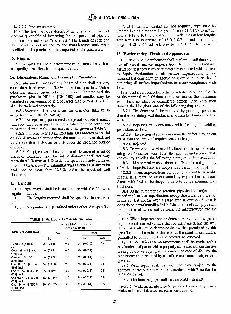
16.2.1 Except for pipe ordered as special outside diameter tolerance pipe or as inside diameter tolerance pipe, variations in outside diameter shall not exceed those given in Table 3.
16.2.2 For pipe over 10 in. [250 mm] OD ordered as special outside diameter tolerance pipe, the outside diameter shall not vary more than 1 % over or 1 % under the specified outside diameter.
16.2.3 For pipe over 10 in. [250 mm] ID ordered as inside diameter tolerance pipe, the inside diameter shall not vary more than 1 % over or 1 % under the specified inside diameter.
16.3 Thickness-The minimum wall thickness at any point shall not be more than 12.5 % under the specified wall thickness.
17. Lengths
17.1 Pipe lengths shall be in accordance with the following regular practice:
17.1.1 The lengths required shall be specified in the order, and
17.1.2 No jointers are permitted unless otherwise specified.
TABLE 3 Variations in Outside Diameter
Permissible Variations in Outside Diameter
NPS [ON Designator] Over Under
in. mm in. mm
Va to 1'h [6 to 40]. Va. (0.015) 0.4 Va. (0.015) 0.4 incl Over 1'12 to 4 [40 to '/32 (0.031) 0.8 V32 (0.031) 0.8 100]. incl Over 4 to 8 [100 to V'6 (0.062) 1.6 %2 (0.031) 0.8 200], incl Over 8 to 18 [200 to %2 (0.093) 2.4 %2 (0.031) 0.8 450]. incl Over 18 to 26 [450 to '/s (0.125) 3.2 %2 (0.031) 0.8 650]. incl Over 26 to 34 [650 to %2 (0.156) 4.0 %2 (0.031) 0.8 850]. incl Over 34 to 48 [850 to 3/'6 (0.187) 4.8 '/32 (0.031) 0.8 1200]. incl
32
17.1.3 If definite lengths are not required, pipe may be ordered in single random lengths of 16 to 22 ft [4.8 to 6.7 m] with 5 % 12 to 16 ft [3.7 to 4.8 m], or in double random lengths with a minimum average of 35 ft [10.7 m] and a minimum length of 22 ft [6.7 m] with 5 % 16 to 22 ft [4.8 to 6.7 m].
18. Workmanship, Finish and Appearance
18.1 The pipe manufacturer shall explore a sufficient number of visual surface imperfections to provide reasonable assurance that they have been properly evaluated with respect to depth. Exploration of all surface imperfections is not required but consideration should be given to the necessity of exploring all surface imperfections to assure compliance with 18.2.
18.2 Surface imperfections that penetrate more than 121/2 % of the nominal wall thickness or encroach on the minimum wall thickness shall be considered defects. Pipe with such defects shall be given one of the following dispositions:
18.2.1 The defect shall be removed by grinding, provided that the remaining wall thickness is within the limits specified in 16.3.
18.2.2 Repaired in accordance with the repair welding provisions of 18.6.
18.2.3 The section of pipe containing the defect may be cut off within the limits of requirements on length.
18.2.4 Rejected. 18.3 To provide a workmanlike finish and basis for evalu
ating conformance with 18.2 the pipe manufacturer shall remove by grinding the following noninjurious imperfections:
18.3.1 Mechanical marks, abrasions (Note 5) and pits, any of which imperfections are deeper than 1/16 in. [1.6 mm].
18.3.2 Visual imperfections commonly referred to as scabs, seams, laps, tears, or s).ivers found by exploration in accordance with 18.1 to be deeper than 5 % of the nominal wall thickness.
18.4 At the purchaser's discretion, pipe shall be subjected to rejection if surface imperfections acceptable under 18.2 are not scattered, but appear over a large area in excess of what is considered a workmanlike finish. Disposition of such pipe shall be a matter of agreement between the manufacturer and the purchaser.
18.5 When imperfections or defects are removed by grinding, a smooth curved surface shall be maintained, and the wall thickness shall not be decreased below that permitted by this specification. The outside diameter at the point of grinding is permitted to be reduced by the amount so removed.
18.5.1 Wall thickness measurements shall be made with a mechanical caliper or with a properly calibrated nondestructive testing device of appropriate accuracy. In case of dispute, the measurement determined by use of the mechanical caliper shall govern.
18.6 Weld repair shall be permitted only subject to the approval of the purchaser and in accordance with Specification A 530/ A 530M.
18.7 The finished pipe shall be reasonably straight.
NOTE 5-Marks and abrasions are defined as cable marks, dinges, guide marks, roll marks, ball scratches, scores, die marks, etc.
• A 106/A 106M - 04b
19. End Finish
19.1 The Pipe shall be furnished to the following practice, unless otherwise specified.
19.1.1 NPS 11/2 [DN 40J and Smaller-All walls shall be either plain-end square cut, or plain-end beveled at the option of the manufacturer.
19.1.2 NPS 2 [DN 50J and Larger-Walls through extra strong weights, shall be plain-end-beveled._
19.1.3 NPS 2 [DN 50J and Larger-Walls over extra strong weights, shall be plain-end square cut.
NOTE 6-Plain-end beveled is defined as plain-end pipe having a bevel angle of 30°, +5° or _0°, as measured from a line drawn perpendicular to the axis of the pipe with a root face of 1/16 ± Y32 in. [1.6 ± 0.8 mm]. Other bevel angles may be specified by agreement between the purchaser and the manufacturer.
20. Number of Tests
20.1 The tensile requirements specified in Section 7 shall be determined on one length of pipe from each lot (Note 3) of 400 lengths or fraction thereof of each size under NPS 6 [DN 150], and from each lot of 200 lengths or fraction thereof of each size NPS 6 [DN 150] and over.
20.2 For pipe NPS 2 [DN 50] and under, the bend test specified in 11.1 shall be made on one pipe from each lot of 400 lengths or fraction thereof of each size. The bend test, where used as permitted by 11.2 or required by 11.3, shall be made on one end of 5 % of the pipe from each lot. For small lots, at least one pipe shall be tested.
20.3 The flattening test specified in Section 12 shall be made on one length of pipe from each lot of 400 lengths or fraction thereof of each size over NPS 2 [DN 50], up to but not including NPS 6 [DN 150], and from each lot of 200 lengths or fraction thereof, of each size NPS 6 [DN 150] and over.
20.4 If any test specimen shows flaws or defective machining, it shall be permissible to discard it and substitute another test specimen.
21. Retests
21.1 If the percentage of elongation of any tension test specimen is less than that given in Table 1 and any part of the fracture is more than % in. [19 mm] from the center of the gage length of a 2-in. [50-mm] specimen as indicated by scribe scratches marked on the specimen before testing, a retest shall be allowed. If a specimen breaks in an inside or outside surface flaw, a retest shall be allowed.
21.2 Should a crop end of a finished pipe fail in the flattening test, one retest is permitted to be made from the failed end. Pipe shall be normalized either before or after the first test, but pipe shall be subjected to only two normalizing treatments.
22. Test Specimens and Test Methods
22.1 On NPS 8 [DN 200] and larger, specimens cut either longitudinally or transversely shall be acceptable for the tension test. On sizes smaller than NPS 8 [DN 200], the longitudinal test only shall be used.
22.2 When round tension test specimens are used for pipe wall thicknesses over 1.0 in. [25.4 mm], the mid-length of the
33
longitudinal axis of such test specimens shall be from a location midway between the inside and outside surfaces of the pipe.
22.3 Test specimens for the bend test specified in Section 11 and for the flattening tests shall consist of sections cut from a pipe. Specimens for flattening tests shall be smooth on the ends and free from burrs, except when made on crop ends.
22.4 Test specimens for the bend test specified in 11.2 and 11.3 shall be cut from one end of the pipe and, unless otherwise specified, shall be taken in a transverse direction. One test specimen shall be taken as close to the outer surface as possible and another from as close to the inner surface as possible. The specimens shall be either liz by V2 in. [12.5 by 12.5 mm] in section or 1 by liz in. [25 by 12.5 mm] in section with the corners rounded to a radius not over VI6 in. [1.6 rom] and need not exceed 6 in. [150 mm] in length. The side of the samples placed in tension during the bend shall be the side closest to the inner and outer surface of the pipe respectively.
22.5 All routine check tests shall be made at room temperature.
23. Certification
23.1 When test reports are requested, in addition to the requirements of Specification A 5301 A 530M, the producer or supplier shall furnish to the purchaser a chemical analysis report for the elements specified in Table 1.
24. Product Marking
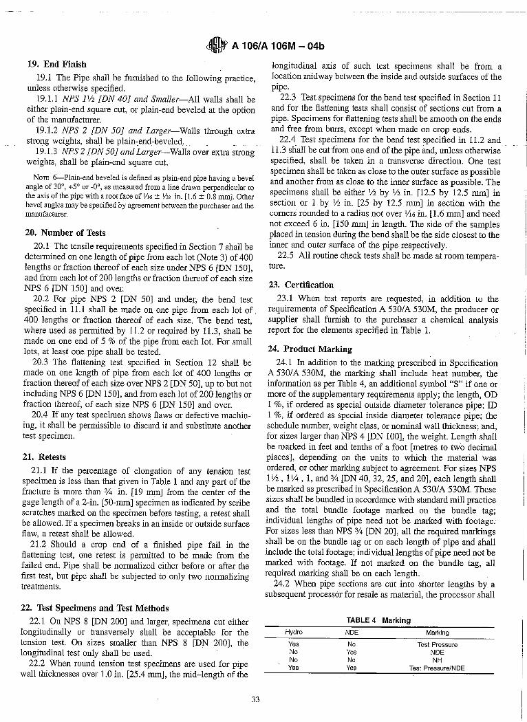
24.1 In addition to the marking prescribed in Specification A 530lA 530M, the marking shall include heat number, the information as per Table 4, an additional symbol "S" if one or more of the supplementary requirements apply; the length, aD 1 %, if ordered as special outside diameter tolerance pipe; ill 1 %, if ordered as special inside diameter tolerance pipe; the schedule number, weight c~ass, or nominal wall thickness; and, for sizes larger than NPS 4 [DN 100], the weight. Length shall be marked in feet and tenths of a foot [metres to two decimal places], depending on the units to which the material was ordered, or other marking subject to agreement. For sizes NPS 11/2, 11/4, 1, and % [DN 40,32,25, and 20], each length shall be marked as prescribed in Specification A 5301 A 530M. These sizes shall be bundled in accordance with standard mill practice and the total bundle footage marked on the bundle tag; individual lengths of pipe need not be marked with footage. For sizes less than NPS % [DN 20], all the required markings shall be on the bundle tag or on each length of pipe and shall include the total footage; individual lengths of pipe need not be marked with footage. If not marked on the bundle tag, all required marking shall be on each length.
24.2 When pipe sections are cut into shorter lengths by a subsequent processor for resale as material, the processor shall
TABLE 4 Marking
Hydro NDE Marking
Yes No Test Pressure No Yes NDE No No NH Yes Yes Test Pressure/NDE
~ A 106/A 106M - 04b
transfer complete identifying information, including the name or brand of the manufacturer to each unmarked cut length, or to metal tags securely attached to bundles of unmarked small diameter pipe. The same material designation shall be included with the information transferred, and the processor's name, trademark, or brand shall be added.
24.3 Bar Coding-In addition to the requirements in 24.1 and 24.2, bar coding is acceptable as a supplementary identification method. The purchaser may specify in the order a specific bar coding system to be used.
25. Government Procurement
25.1 When specified in the contract, material shall be preserved, packaged, and packed in accordance with the requirements of MIL-STD-163. The applicable levels shall be as specified in the contract. Marking for the shipment of such
material shall be in accordance with Fed. Std. No. 123 for civil agencies and MIL-STD-129 or Fed. Std. No. 183 if continuous marking is required for military agencies.
25.2 Inspection-Unless otherwise specified in the contract, the producer is responsible for the performance of all inspection and test requirements specified herein. Except as otherwise specified in the contract, the producer shall use his own, or any other suitable facilities for the performance of the inspection and test requirements specified herein, unless disapproved by the purchaser. The purchaser shall have the right to perform any of the inspections and tests set forth in this specification where such inspections are deemed necessary to ensure that the material conforms to the prescribed requirements.
26. Keywords
26.1 carbon steel pipe; seamless steel pipe; steel pipe
SUPPLEMENTARY REQUIREMENTS
One or more of the following supplementary requirements shall apply only when specified in the purchase order. The purchaser may specify a different frequency of test or analysis than is provided in the supplementary requirement. Subject to agreement between the purchaser and manufacturer, retest and retreatment provisions of these supplementary requirements may also be modified.
S1. Product Analysis
S 1.1 Product analysis shall be made on each length of pipe. Individual lengths 'failing to conform to the chemical composition requirements shall be rejected,
S2. Transverse Tension Test
S2.1 A transverse tension test shall be made on a specimen from one end. or both ends of each pipe NPS 8 [DN 200] and over. If this supplementary requirement is specified, the number of tests per pipe shall also be specified. If a specimen from any length fails to meet the required tensile properties (tensile, yield, and elongation), that length shall be rejected subject to retreatment in accordance with Specification A 5301 A 530M and satisfactory retest.
S3. Flattening Test
S3.1 The flattening test of Specification A 530/A 530M shall be made on a specimen from one end or both ends of each pipe. Crop ends may be used. If this supplementary requirement is specified, the number of tests per pipe shall also be specified. If a specimen from any length fails because of lack of ductility prior to satisfactory completion of the first step of the flattening test requirement, that pipe shall be rejected subject to retreatment in accordance with Specification A 5301 A 530M and satisfactory retest. If a specimen from any length of pipe fails because of a lack of soundness, that length shall be rejected, unless subsequent retesting indicates that the remaining length is sound.
S4. Metal Structure and Etching Test
S4.1 The steel shall be homogeneous as shown by etching tests conducted in accordance with the appropriate sections of Method E 381. Etching tests shall be made on a cross section
34
from one end or both ends of each pipe and shall show sound and reasonably uniform material free from injurious laminations, cracks, and similar objectionable defects. If this supplementary requirement is specified, the number of tests per pipe required shall also be specified. If a specimen from any length shows objectionable defects, the length shall be rejected, subject to removal of the defective end and subsequent retests indicating the remainder of the length to be sound and reasonably uniform material.
S5. Carbon Equivalent
S5.1 The steel shall conform to a carbon equivalent (CE) of 0.50 maximum as determined by the following formula:
%Mn %Cr + %Mo + %V %Ni + %Cu CE = %C + -6- + 5 + 15
S5.2 A lower CE maximum may be agreed upon between the purchaser and the producer.
S5.3 The CE shall be reported on the test report.
S6. Heat Treated Test Specimens
S6.1 At the request of the purchaser, one tensile test shall be performed by the manufacturer on a test· specimen from each heat of steel furnished which has been either stress relieved at 1250 OF or normalized at 1650 OF, as specified by the purchaser. Other stress relief or annealing temperatures, as appropriate to the analysis, may be specified by agreement between the purchaser and the manufacturer. The results of this test shall meet the requirements of Table 1.
S7. Internal Cleanliness-Government Orders
S7.1 The internal surface of hot finished ferritic steel pipe and tube shall be manufactured to a free of scale condition
• A 106/A 106M - 04b
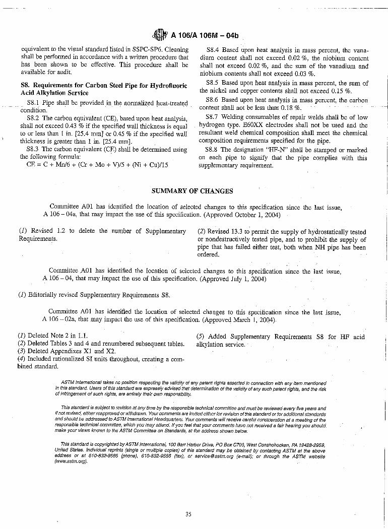
equivalent to the visual standard listed in SSPC-SP6. Cleaning shall be performed in accordance with a written procedure that has been shown to be effective. This procedure shall be available for audit.
S8. Requirements for Carbon Steel Pipe for Hydrofluoric Acid Alkylation Service
S8.1 Pipe shall be provided inthe normalized heat-treated - condition.
S8.2 The carbon equivalent (CE), based upon heat analysis, shall not exceed 0.43 % if the specified wall thickness is equal to or less than 1 in. [25.4 mm] or 0.45 % if the specified wall thickness is greater than 1 in. [25.4 mm].
S8.3 The carbon equivalent (CE) shall be determined using the following formula: -
CE = C + Mn/6 + (Cr + Mo + V)/5 + (Ni + Cu)/15
S8.4 Based upon heat analysis in mass percent, the vanadium content shall not exceed 0.02 %, the niobium content shall not exceed 0.02 %, and the sum of the vanadium and niobium contents shall not exceed 0.03 %.
S8.5 Based upon heat analysis in mass percent, the sum of the nickel and copper contents shall not exceed 0.15 %.
S8.6 Based upon heat analysis in mass percent, the carbon contentshall not be less than 0.18 %.
S8.7 Welding consumables of repair welds shall be of low hydrogen type. E60XX electrodes shall not be used and the resultant weld chemical composition shall meet the chemical composition requirements specified for the pipe.
S8.8 The designation "HF-N" shall be stamped or marked on each pipe to signify that the pipe complies with this supplementary requirement.
SUMMARY OF CHANGES
Committee A01 has identified the location of selected changes to this specification since the last issue, A 106 - 04a, that may impact the use of this specification. (Approved October 1, 2004)
(1) Revised 1.2 to delete the number of Supplementary Requiremen!s.
(2) Revised 13.3 to permit the supply of hydrostatically tested or nondestructively tested pipe, and to prohibit the supply of pipe that has failed either test, both when NH pipe has been ordered.
Committee A01 has identified the location of selected changes to this specification since the last issue, A 106 - 04, that may impact the use of this specification. (Approved July 1, 2004)
(1) Editorially revised Supplementary Requirements S8.
Committee A01 has identified the location of selected changes to this specification since the last issue, A 106 - 02a, that may impact the use of this specification, (Approved March 1, 2004)
(1) Deleted Note 2 in 1.1. (2) Deleted Tables 3 and 4 and renumbered subsequent tables. (3) Deleted Appendixes Xl and X2. (4) Included rationalized SI units throughout, creating a combined standard.
(5) Added Supplementary Requirements S8 for HF acid alkylation service.
ASTM International takes no position respecting the validity of any patent rights asserted in connection with any item mentioned in this standard. Users of this standard are expressly advised that determination of the validity of any such patent rights, and the risk of infringement of such rights, are entirely their own responsibility.
This standard is subject to revision at any time by the responsible technical committee and must be reviewed evelJl five years and if not revised, either reapproved or withdrawn. Your comments are invited either for revision of this standard or for additional standards and should be addressed to ASTM International Headquarters. Your commf!nts will receive careful consideration at a meeting of the responsible technical committee, which you may attend. If you feel that your comments have not received a fair hearing you should make your views known to the ASTM Committee on Standards, at the address shown below.
This standard is copyrighted by ASTM International, 100 Barr Harbor Drive, PO Box C700, West Conshohocken, PA 19428-2959, United States. Individual reprints (single or multiple copies) of this standard may be obtained by contacting ASTM at the above address or at 610-832-9585 (phone), 610-832-9555 (fax), or [email protected] (e-mail); or through the ASTM website (www.astm.org).
35