GW-7238D J1939 to MBTCP Server / MBRTU Slave Gateway User’s Manual (Ver.1.1, May. 2013) --- 1
User’s Manual
www.icpdas.com
GW-7238D
J1939 to Modbus TCP Server / RTU
Slave Gateway
GW-7238D J1939 to MBTCP Server / MBRTU Slave Gateway User’s Manual (Ver.1.1, May. 2013) --- 2
Warranty All products manufactured by ICP DAS are under warranty regarding
defective materials for a period of one year from the date of delivery to the original purchaser. Warning
ICP DAS assumes no liability for damages resulting from the use of this product. ICP DAS reserves the right to change this manual at any time without notice. The information furnished by ICP DAS is believed to be accurate and reliable. However, no responsibility is assumed by ICP DAS for its use, or for any infringements of patents or other rights of third parties resulting from its use. Copyright
Copyright 2013 by ICP DAS. All rights are reserved.
Trademark The names used for identification only may be registered trademarks
of their respective companies.
Document Revision
Version Date Description of changes 1.0 2010-11-12 First Release Revision
1.1 2013-05-29 Add XC-100 Rev1.9 I/O expansion board
jumper selection description
GW-7238D J1939 to MBTCP Server / MBRTU Slave Gateway User’s Manual (Ver.1.1, May. 2013) --- 3
Table of Contents 1. Introduction ....................................... ................................................5
1.1 Mode of operation .............................................................................. 5
1.2 Features............................................................................................. 6
1.3 Specifications ..................................................................................... 6
2. Hardware ........................................... ................................................8
2.1 Block Diagram.................................................................................... 8
2.2 Pin Assignment .................................................................................. 9
2.2.1 RS-232 & RS-485 & Power supply Interface.................................... 9
2.2.2 CAN bus Interface............................................................................ 9
2.2.3 Ethernet Connect ........................................................................... 10
2.3 Hardware Connection .......................................................................11
2.3.1 CAN port connection .......................................................................11
2.3.2 Serial / Ethernet / Power port connection....................................... 12
2.4 Terminator Resistor Settings ............................................................ 12
2.5 Init / Normal Dip-switch .................................................................... 14
2.5.1 Firmware Update Mode.................................................................. 14
2.5.2 Firmware Operation Mode.............................................................. 16
2.6 LED Indication.................................................................................. 16
2.7 5-digits 7-segment LED Displays ..................................................... 18
3. Software........................................... ................................................21
3.1 Configuration Tool – GW-7238D Utility............................................. 21
3.2 GW-7238D Utility ............................................................................. 22
3.2.1 Connection Screen......................................................................... 22
3.2.2 Main Screen ................................................................................... 23
4. Communication Network.............................. ..................................31
4.1 Modbus Network .............................................................................. 31
4.1.1 Supported Modbus Functions ........................................................ 31
4.1.2 Modbus Address ............................................................................ 31
4.2 J1939 Network ................................................................................. 33
4.2.1 Communication Methods................................................................ 33
4.2.2 Parameter Groups.......................................................................... 33
4.2.3 Suspect Parameter Number (SPN) ................................................ 34
4.2.4 J1939 Message Transmission........................................................ 35
4.2.5 J1939 Receiving Messages ........................................................... 36
4.2.6 Transport Protocol for Large Messages ......................................... 36
5. Application ........................................ ..............................................37
5.1 Hardware Installation ....................................................................... 37
GW-7238D J1939 to MBTCP Server / MBRTU Slave Gateway User’s Manual (Ver.1.1, May. 2013) --- 4
5.2 GW-7238D Utility Configuration ....................................................... 40
5.2.1 Modbus Network Configuration ...................................................... 40
5.2.2 J1939 Network Configuration ......................................................... 40
5.2.3 J1939 I/O Configuration ................................................................. 41
5.2.4 Upload Parameter to the GW-7238D ............................................. 43
5.3 Modbus Communication – Modbus RTU ......................................... 44
5.4 Modbus Communication – Modbus TCP.......................................... 47
6. Troubleshooting.................................... ..........................................51

GW-7238D J1939 to MBTCP Server / MBRTU Slave Gateway User’s Manual (Ver.1.1, May. 2013) --- 5
1. Introduction
The GW-7238D is a gateway that provides conversion between J1939 and Modbus TCP/RTU protocol. For J1939 network, the GW-7238D supports PDU1, PDU2, broadcast and destination specific type of J1939 messages. For Modbus TCP/RTU network, the GW-7238D is a Modbus TCP server / RTU slave to reply the request from Modbus TCP client / RTU master. Utility software is provided for users to configure J1939 and Modbus TCP/RTU setting in the GW-7238D. The application fields can be diesel power-train applications, In-Vehicle networks for trucks and buses, etc.
The following is the application architecture for the GW-7238D:
Figure 1-1: Application of the GW-7238D
1.1 Mode of operation The GW-7238D provides centralized data storage, for data that is
shared between the Modbus and J1939 networks. Data is placed into the GW-7238D by one network interface, and allowing the data to be read or written through the other network interface.
GW-7238D J1939 to MBTCP Server / MBRTU Slave Gateway User’s Manual (Ver.1.1, May. 2013) --- 6
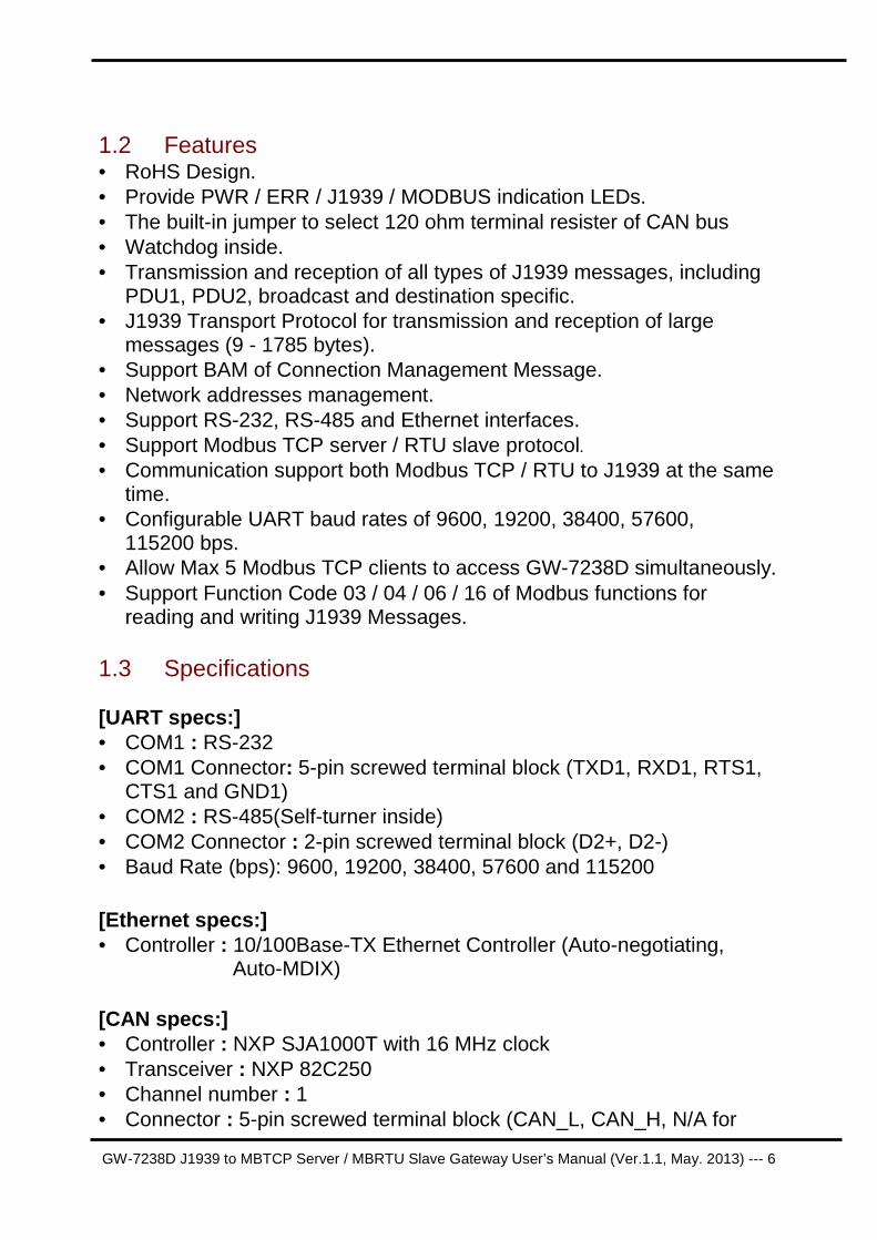
1.2 Features • RoHS Design. • Provide PWR / ERR / J1939 / MODBUS indication LEDs. • The built-in jumper to select 120 ohm terminal resister of CAN bus • Watchdog inside. • Transmission and reception of all types of J1939 messages, including
PDU1, PDU2, broadcast and destination specific. • J1939 Transport Protocol for transmission and reception of large
messages (9 - 1785 bytes). • Support BAM of Connection Management Message. • Network addresses management. • Support RS-232, RS-485 and Ethernet interfaces. • Support Modbus TCP server / RTU slave protocol. • Communication support both Modbus TCP / RTU to J1939 at the same
time. • Configurable UART baud rates of 9600, 19200, 38400, 57600,
115200 bps. • Allow Max 5 Modbus TCP clients to access GW-7238D simultaneously. • Support Function Code 03 / 04 / 06 / 16 of Modbus functions for
reading and writing J1939 Messages.
1.3 Specifications [UART specs:] • COM1 : RS-232 • COM1 Connector: 5-pin screwed terminal block (TXD1, RXD1, RTS1,
CTS1 and GND1) • COM2 : RS-485(Self-turner inside) • COM2 Connector : 2-pin screwed terminal block (D2+, D2-) • Baud Rate (bps): 9600, 19200, 38400, 57600 and 115200
[Ethernet specs:] • Controller : 10/100Base-TX Ethernet Controller (Auto-negotiating,
Auto-MDIX)
[CAN specs:] • Controller : NXP SJA1000T with 16 MHz clock • Transceiver : NXP 82C250 • Channel number : 1 • Connector : 5-pin screwed terminal block (CAN_L, CAN_H, N/A for
GW-7238D J1939 to MBTCP Server / MBRTU Slave Gateway User’s Manual (Ver.1.1, May. 2013) --- 7
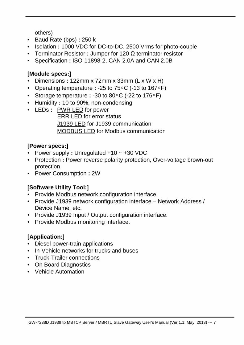
others) • Baud Rate (bps) : 250 k • Isolation : 1000 VDC for DC-to-DC, 2500 Vrms for photo-couple • Terminator Resistor : Jumper for 120 Ω terminator resistor • Specification : ISO-11898-2, CAN 2.0A and CAN 2.0B [Module specs:] • Dimensions : 122mm x 72mm x 33mm (L x W x H) • Operating temperature : -25 to 75º C (-13 to 167º F) • Storage temperature : -30 to 80º C (-22 to 176º F) • Humidity : 10 to 90%, non-condensing • LEDs : PWR LED for power
ERR LED for error status J1939 LED for J1939 communication MODBUS LED for Modbus communication
[Power specs:] • Power supply : Unregulated +10 ~ +30 VDC • Protection : Power reverse polarity protection, Over-voltage brown-out
protection • Power Consumption : 2W [Software Utility Tool:] • Provide Modbus network configuration interface. • Provide J1939 network configuration interface – Network Address /
Device Name, etc. • Provide J1939 Input / Output configuration interface. • Provide Modbus monitoring interface.
[Application:] • Diesel power-train applications • In-Vehicle networks for trucks and buses • Truck-Trailer connections • On Board Diagnostics • Vehicle Automation
GW-7238D J1939 to MBTCP Server / MBRTU Slave Gateway User’s Manual (Ver.1.1, May. 2013) --- 8
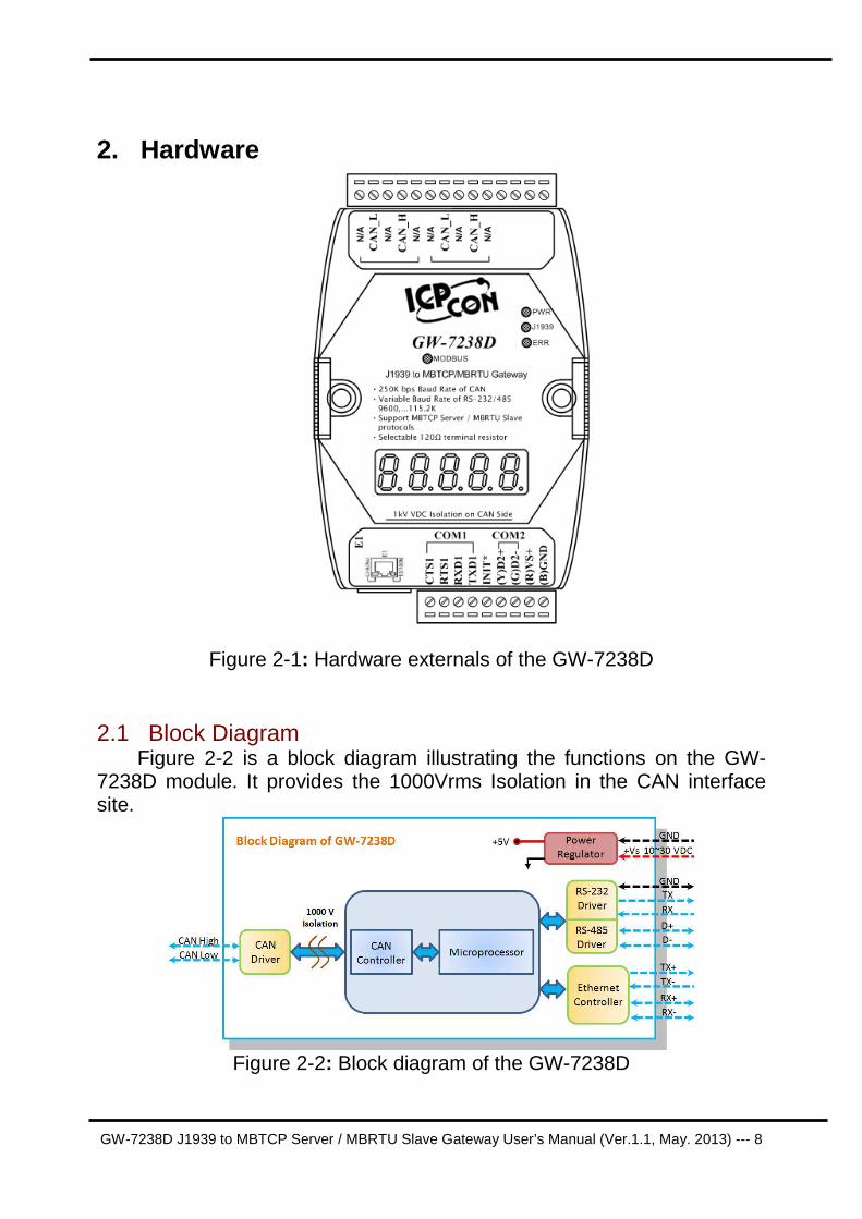
2. Hardware
Figure 2-1: Hardware externals of the GW-7238D
2.1 Block Diagram Figure 2-2 is a block diagram illustrating the functions on the GW-
7238D module. It provides the 1000Vrms Isolation in the CAN interface site.
Figure 2-2: Block diagram of the GW-7238D

GW-7238D J1939 to MBTCP Server / MBRTU Slave Gateway User’s Manual (Ver.1.1, May. 2013) --- 9
2.2 Pin Assignment
2.2.1 RS-232 & RS-485 & Power supply Interface The GW-7238D provides one RS-232 interface and one RS-485
interface with hardware flow control. The GND-signal of COM1 is shared with pin-9, GND. The pin assignment is shown in table 2-1.
Table 2-1: COM Connector Pin Assignment Pin No. Name Description
1 CTS1 CTS pin of COM1 (RS-232) 2 RTS1 RTS pin of COM1 (RS-232) 3 RXD1 RXD pin of COM1 (RS-232) 4 TXD1 TXD pin of COM1 (RS-232)
5 INIT* Initial pin for enable/disable
AUTOEXEC.BAT 6 D2+ Data+ pin of COM2 (RS-485) 7 D2- Data- pin of COM2 (RS-485)
8 VS+ V+ of power supply
(+10V to +30V DC unregulated) 9 GND GND of power supply
Figure 2-3: COM Connector on the GW-7238D
2.2.2 CAN bus Interface In order to provide an easy CAN bus wiring, the GW-7238D supplies
one CAN port with two CAN bus connector interfaces. Each connecter built on the GW-7238D looks like as figure 2-4 and table 2-2.
GW-7238D J1939 to MBTCP Server / MBRTU Slave Gateway User’s Manual (Ver.1.1, May. 2013) ---
10
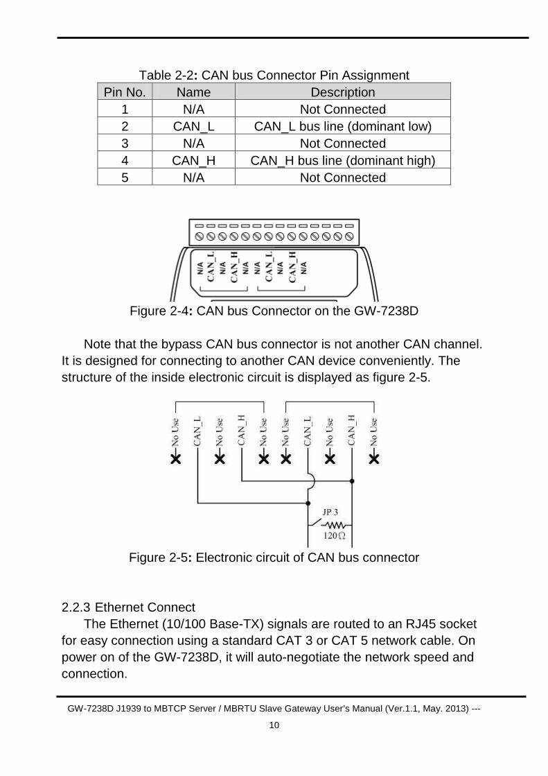
Table 2-2: CAN bus Connector Pin Assignment Pin No. Name Description
1 N/A Not Connected 2 CAN_L CAN_L bus line (dominant low) 3 N/A Not Connected 4 CAN_H CAN_H bus line (dominant high) 5 N/A Not Connected
Figure 2-4: CAN bus Connector on the GW-7238D
Note that the bypass CAN bus connector is not another CAN channel.
It is designed for connecting to another CAN device conveniently. The structure of the inside electronic circuit is displayed as figure 2-5.
Figure 2-5: Electronic circuit of CAN bus connector
2.2.3 Ethernet Connect The Ethernet (10/100 Base-TX) signals are routed to an RJ45 socket
for easy connection using a standard CAT 3 or CAT 5 network cable. On power on of the GW-7238D, it will auto-negotiate the network speed and connection.
GW-7238D J1939 to MBTCP Server / MBRTU Slave Gateway User’s Manual (Ver.1.1, May. 2013) ---
11
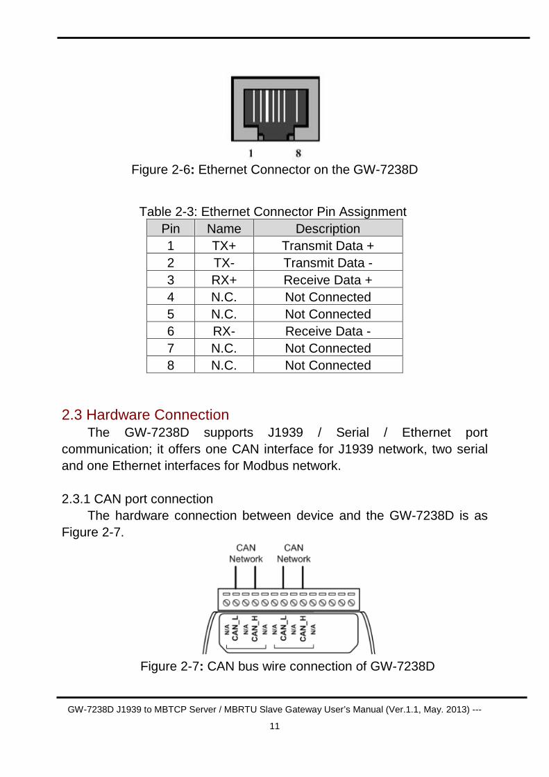
Figure 2-6: Ethernet Connector on the GW-7238D
Table 2-3: Ethernet Connector Pin Assignment Pin Name Description 1 TX+ Transmit Data + 2 TX- Transmit Data - 3 RX+ Receive Data + 4 N.C. Not Connected 5 N.C. Not Connected 6 RX- Receive Data - 7 N.C. Not Connected 8 N.C. Not Connected
2.3 Hardware Connection The GW-7238D supports J1939 / Serial / Ethernet port
communication; it offers one CAN interface for J1939 network, two serial and one Ethernet interfaces for Modbus network.
2.3.1 CAN port connection The hardware connection between device and the GW-7238D is as
Figure 2-7.
Figure 2-7: CAN bus wire connection of GW-7238D
GW-7238D J1939 to MBTCP Server / MBRTU Slave Gateway User’s Manual (Ver.1.1, May. 2013) ---
12
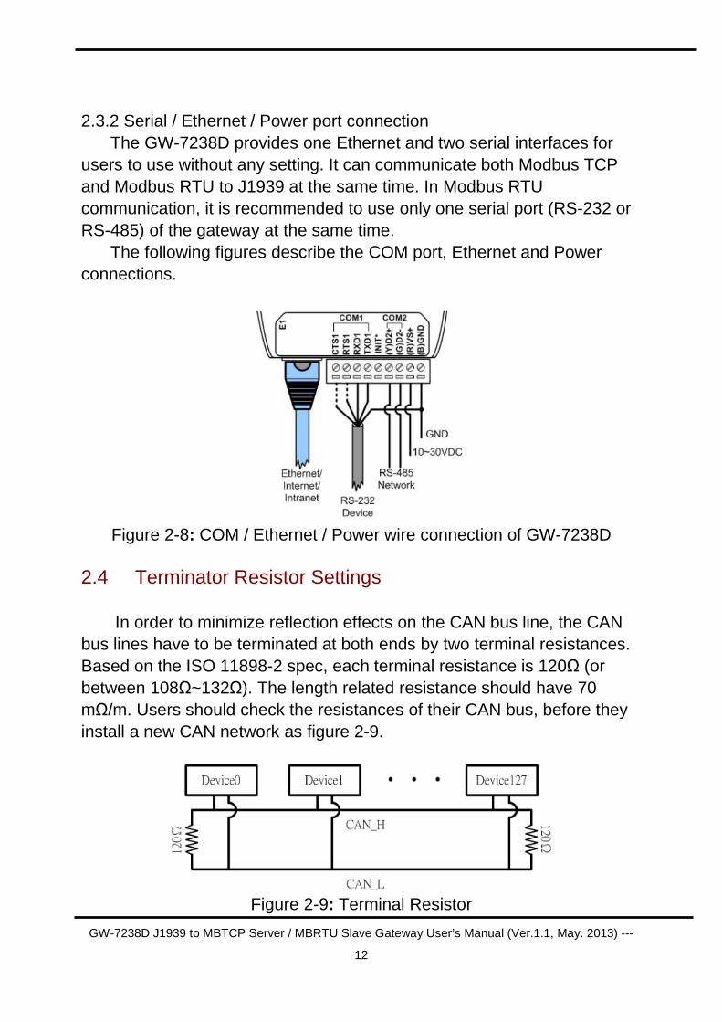
2.3.2 Serial / Ethernet / Power port connection The GW-7238D provides one Ethernet and two serial interfaces for
users to use without any setting. It can communicate both Modbus TCP and Modbus RTU to J1939 at the same time. In Modbus RTU communication, it is recommended to use only one serial port (RS-232 or RS-485) of the gateway at the same time.
The following figures describe the COM port, Ethernet and Power connections.
Figure 2-8: COM / Ethernet / Power wire connection of GW-7238D
2.4 Terminator Resistor Settings
In order to minimize reflection effects on the CAN bus line, the CAN bus lines have to be terminated at both ends by two terminal resistances. Based on the ISO 11898-2 spec, each terminal resistance is 120Ω (or between 108Ω~132Ω). The length related resistance should have 70 mΩ/m. Users should check the resistances of their CAN bus, before they install a new CAN network as figure 2-9.
Figure 2-9: Terminal Resistor
GW-7238D J1939 to MBTCP Server / MBRTU Slave Gateway User’s Manual (Ver.1.1, May. 2013) ---
13
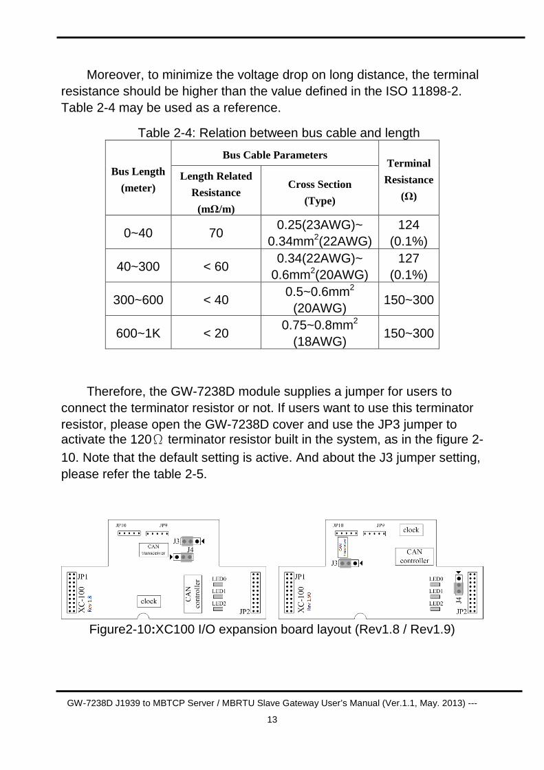
Moreover, to minimize the voltage drop on long distance, the terminal resistance should be higher than the value defined in the ISO 11898-2. Table 2-4 may be used as a reference.
Table 2-4: Relation between bus cable and length
Bus Cable Parameters
Bus Length
(meter) Length Related
Resistance
(mΩ/m)
Cross Section
(Type)
Terminal
Resistance
(Ω)
0~40 70 0.25(23AWG)~
0.34mm2(22AWG) 124
(0.1%)
40~300 < 60 0.34(22AWG)~
0.6mm2(20AWG) 127
(0.1%)
300~600 < 40 0.5~0.6mm2
(20AWG) 150~300
600~1K < 20 0.75~0.8mm2
(18AWG) 150~300
Therefore, the GW-7238D module supplies a jumper for users to
connect the terminator resistor or not. If users want to use this terminator resistor, please open the GW-7238D cover and use the JP3 jumper to activate the 120Ω terminator resistor built in the system, as in the figure 2-10. Note that the default setting is active. And about the J3 jumper setting, please refer the table 2-5.
Figure2-10:XC100 I/O expansion board layout (Rev1.8 / Rev1.9)
GW-7238D J1939 to MBTCP Server / MBRTU Slave Gateway User’s Manual (Ver.1.1, May. 2013) ---
14
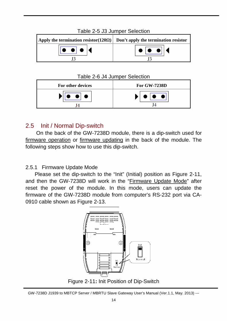
Table 2-5 J3 Jumper Selection
Apply the termination resistor(120Ω) Don’t apply the termination resistor
Table 2-6 J4 Jumper Selection
For other devices For GW-7238D
2.5 Init / Normal Dip-switch On the back of the GW-7238D module, there is a dip-switch used for
firmware operation or firmware updating in the back of the module. The following steps show how to use this dip-switch.
2.5.1 Firmware Update Mode Please set the dip-switch to the “Init” (Initial) position as Figure 2-11,
and then the GW-7238D will work in the “Firmware Update Mode” after reset the power of the module. In this mode, users can update the firmware of the GW-7238D module from computer’s RS-232 port via CA-0910 cable shown as Figure 2-13.
Figure 2-11: Init Position of Dip-Switch
GW-7238D J1939 to MBTCP Server / MBRTU Slave Gateway User’s Manual (Ver.1.1, May. 2013) ---
15
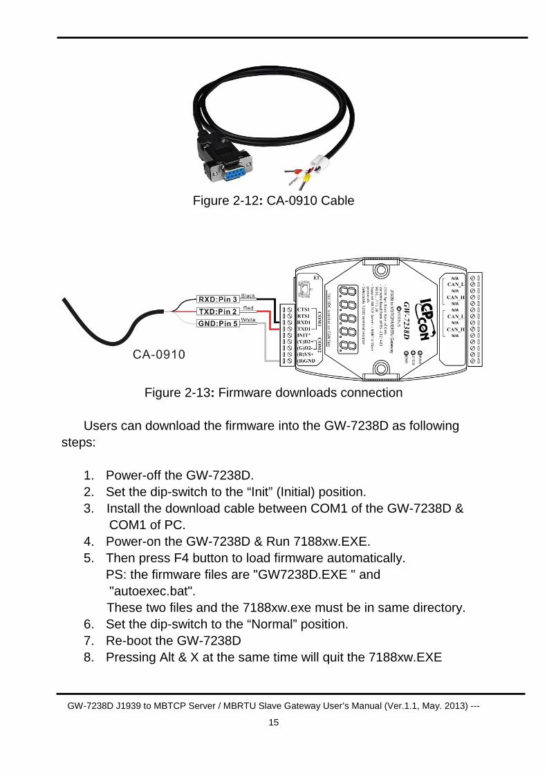
Figure 2-12: CA-0910 Cable
Figure 2-13: Firmware downloads connection
Users can download the firmware into the GW-7238D as following
steps: 1. Power-off the GW-7238D. 2. Set the dip-switch to the “Init” (Initial) position. 3. Install the download cable between COM1 of the GW-7238D &
COM1 of PC. 4. Power-on the GW-7238D & Run 7188xw.EXE. 5. Then press F4 button to load firmware automatically. PS: the firmware files are "GW7238D.EXE " and
"autoexec.bat". These two files and the 7188xw.exe must be in same directory.
6. Set the dip-switch to the “Normal” position. 7. Re-boot the GW-7238D 8. Pressing Alt & X at the same time will quit the 7188xw.EXE

GW-7238D J1939 to MBTCP Server / MBRTU Slave Gateway User’s Manual (Ver.1.1, May. 2013) ---
16
The GW-7238D firmware and 7188xw.exe can be downloaded from http://ftp.icpdas.com/pub/cd/fieldbus_cd/J1939/gateway/GW-
7238D/firmware.
2.5.2 Firmware Operation Mode In the operation mode, users need to set the dip-switch to the
“Normal” position as Figure 2-14 and reset the power. The GW-7238D can run in the operation mode. In this mode, users can use the Modbus Master command to set / get J1939 messages via COM or Ethernet interface.
Figure 2-14: Normal Position of Dip-Switch
2.6 LED Indication The GW-7238D includes four single-color LED displays to indicate the
status of module. The following are the illustration of these LEDs, shown as Figure 2-15.
(1) PWR LED :
It is used to help users to check whether the GW-7238D is standby. If the module is working in “firmware operation” mode, the PWR LED is always turned on.
(2) ERR LED :
It is used for demonstrating an error that has occurred. The ERR LED
GW-7238D J1939 to MBTCP Server / MBRTU Slave Gateway User’s Manual (Ver.1.1, May. 2013) ---
17
is normally turned on when the module works in a good condition. When a error is happened, the ERR LED will blink per 500 ms.
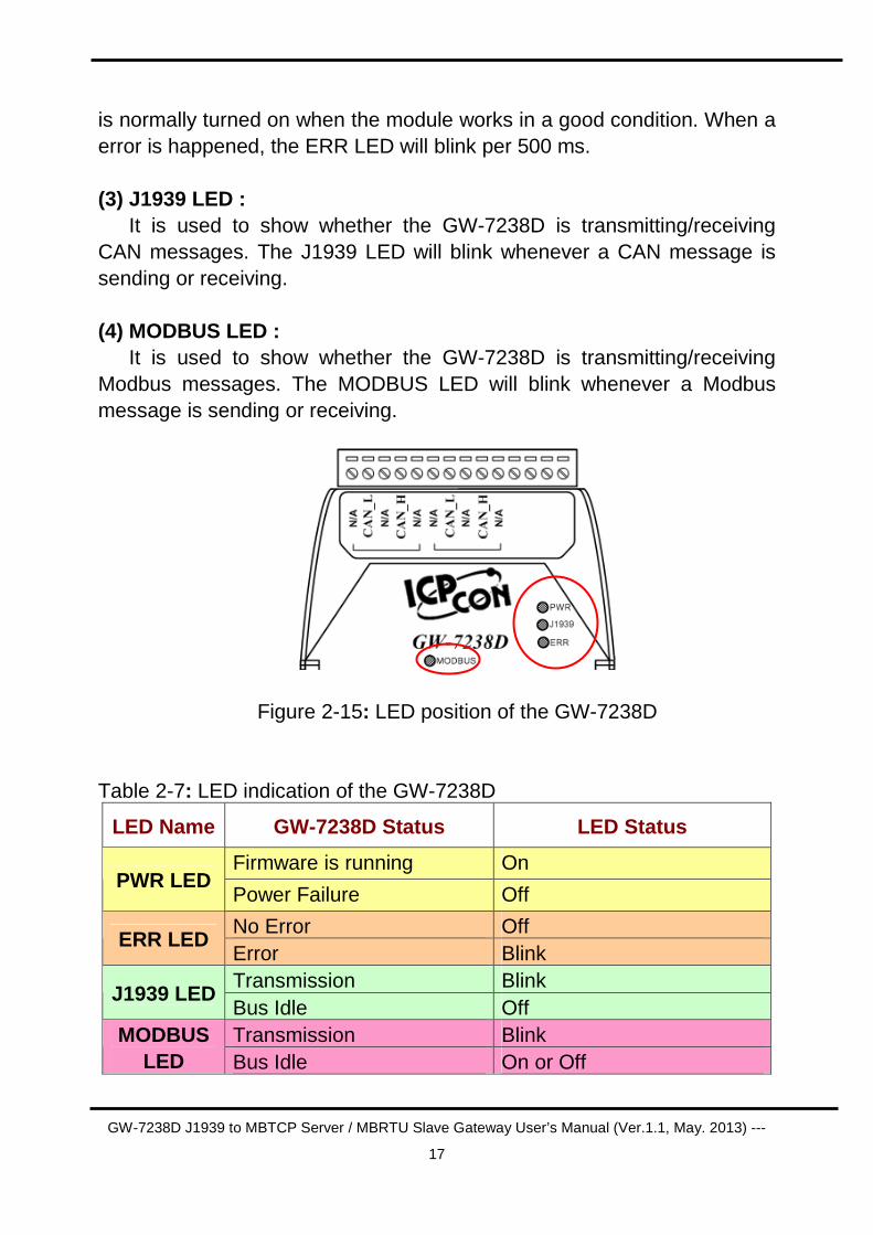
(3) J1939 LED :
It is used to show whether the GW-7238D is transmitting/receiving CAN messages. The J1939 LED will blink whenever a CAN message is sending or receiving.
(4) MODBUS LED :
It is used to show whether the GW-7238D is transmitting/receiving Modbus messages. The MODBUS LED will blink whenever a Modbus message is sending or receiving.
Figure 2-15: LED position of the GW-7238D
Table 2-7: LED indication of the GW-7238D
LED Name GW-7238D Status LED Status
Firmware is running On PWR LED
Power Failure Off
No Error Off ERR LED
Error Blink Transmission Blink
J1939 LED Bus Idle Off Transmission Blink MODBUS
LED Bus Idle On or Off
GW-7238D J1939 to MBTCP Server / MBRTU Slave Gateway User’s Manual (Ver.1.1, May. 2013) ---
18
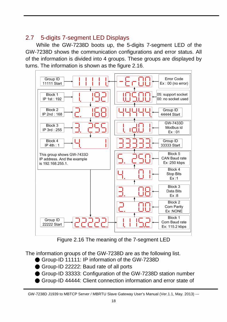
2.7 5-digits 7-segment LED Displays While the GW-7238D boots up, the 5-digits 7-segment LED of the
GW-7238D shows the communication configurations and error status. All of the information is divided into 4 groups. These groups are displayed by turns. The information is shown as the figure 2.16.
Figure 2.16 The meaning of the 7-segment LED
The information groups of the GW-7238D are as the following list. Group-ID 11111: IP information of the GW-7238D Group-ID 22222: Baud rate of all ports Group-ID 33333: Configuration of the GW-7238D station number Group-ID 44444: Client connection information and error state of
GW-7238D J1939 to MBTCP Server / MBRTU Slave Gateway User’s Manual (Ver.1.1, May. 2013) ---
19
the GW-7238D The IP information format of the GW-7238D is given as follows: Group-ID of 5-digit LED: 11111 LED-1: Indicator, can be 1 or 2 or 3 or 4 for 4 sections of IP
address LED-2~5: IP address The LED shows Group-ID first, and then shows its IP address as the
figure 2.14. If users change the IP address, the value shown on the LED will be changed immediately. The default IP address is 192.168.255.1 and
the LED-show sequence is given as above diagram. The configurations of the COM 1/2 and CAN port are given as follows: Group-ID of 5-digit LED: 22222 LED-1: COM1 / COM2 Baud rate, this value needs to multiply by
1000. The range is from 9.6~115.2 (means 9.6 kbps ~ 115.2 kbps)
LED-2: Parity bit, 0=no parity, 1=odd parity, 2=even parity LED-3: Data bit, fixed at 8 LED-4: Stop bit, 1 or 2 LED-5: CAN Baud rate, this value needs to multiply by 1000. The
value is fixed at 250 (means 250 kbps) The configuration of the communication is given as follows: Group-ID of 5-digit LED: 33333 LED-1: Indicators, fixed at 1 LED-2, 3: fix string, “id.” LED-4, 5: The Modbus station ID of the GW-7238D
The connection-client information is given as follows: Group-ID of 5-digit LED: 44444 LED-1: Indicators, fixed at 1 LED-2, 3: Total supported socket numbers (5 sockets) LED-4, 5: Numbers of sockets are used by clients, default 0 If any client connects to the GW-7238D, the numbers of the used-
socket will be increased. The GW-7238D allows 5 clients for connection.
GW-7238D J1939 to MBTCP Server / MBRTU Slave Gateway User’s Manual (Ver.1.1, May. 2013) ---
20
So if the used-socket number is 5, no more clients can link to the GW-7238D. The error status of the GW-7238D is given as follows: LED-1~3: fix string, “-.Er” LED-4, 5: Error code, normal is 00. The details of the error codes
are shown below.
Table 2-8 GW-7238D error status Error Code Status
00 No Error 01 Can’t Claim Address in J1939 Network 02 CAN Bus-Off 03 CAN Bus Transmission Fail
GW-7238D J1939 to MBTCP Server / MBRTU Slave Gateway User’s Manual (Ver.1.1, May. 2013) ---
21
3. Software This chapter describes how the GW-7238D J1939 to Modbus
RTU/TCP Interface is configured using the configuration tool (GW-7238D Utility).
3.1 Configuration Tool – GW-7238D Utility
The GW-7238D configuration tool allows you to configure the parameters associated with the Modbus and J1939 network interfaces as well as to layout of the I/O table and set up the contents.
GW-7238D Utility is a Microsoft Windows application that
communicates with a GW-7238D over a standard RS-232/RS-485 serial link and Ethernet link by using the PC serial and Ethernet port. It is compatible with Microsoft Windows 95, 98, NT, 2000, XP, Vista and 7.
The GW-7238D Utility can be downloaded from
http://ftp.icpdas.com/pub/cd/fieldbus_cd/J1939/gateway/gw-7238D/software/utility.
GW-7238D J1939 to MBTCP Server / MBRTU Slave Gateway User’s Manual (Ver.1.1, May. 2013) ---
22
3.2 GW-7238D Utility
The following is the main screens provided by GW-7238D Utility.
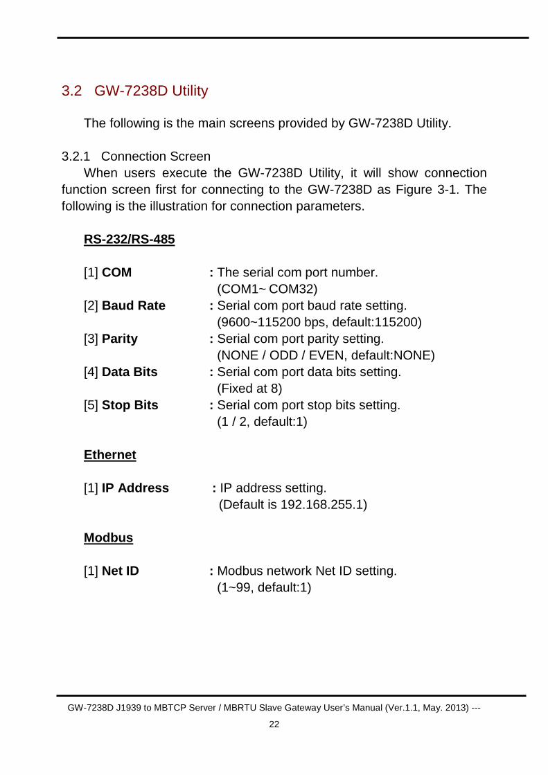
3.2.1 Connection Screen When users execute the GW-7238D Utility, it will show connection
function screen first for connecting to the GW-7238D as Figure 3-1. The following is the illustration for connection parameters.
RS-232/RS-485 [1] COM : The serial com port number.
(COM1~ COM32) [2] Baud Rate : Serial com port baud rate setting. (9600~115200 bps, default:115200) [3] Parity : Serial com port parity setting. (NONE / ODD / EVEN, default:NONE) [4] Data Bits : Serial com port data bits setting. (Fixed at 8) [5] Stop Bits : Serial com port stop bits setting. (1 / 2, default:1) Ethernet [1] IP Address : IP address setting.
(Default is 192.168.255.1) Modbus [1] Net ID : Modbus network Net ID setting. (1~99, default:1)
GW-7238D J1939 to MBTCP Server / MBRTU Slave Gateway User’s Manual (Ver.1.1, May. 2013) ---
23
Figure 3-1: Connection Screen of GW-7238D Utility
After finish the connection setting, please click “Connect ” button to
connect to the GW-7238D module.
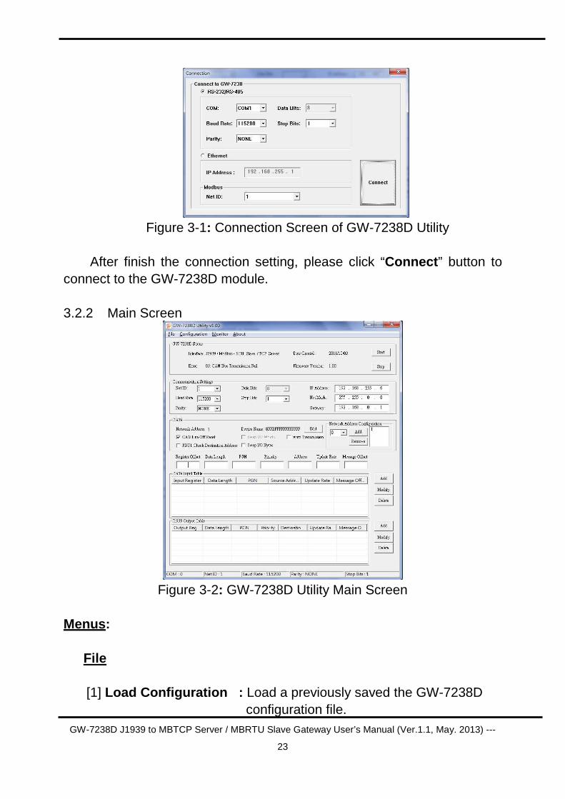
3.2.2 Main Screen
Figure 3-2: GW-7238D Utility Main Screen
Menus :
File [1] Load Configuration : Load a previously saved the GW-7238D
configuration file.
GW-7238D J1939 to MBTCP Server / MBRTU Slave Gateway User’s Manual (Ver.1.1, May. 2013) ---
24
[2] Save Configuration : Save the current GW-7238D configuration to a file.
[3] Download Parameter: Download the configuration from the GW-7238D module and shown on the Utility’s interface.
[4] Upload Parameter : Upload the configuration shown on the Utility’s interface to the GW-7238D module. Configuration [1] Connect to GW-7238D : Establish a connection with the GW-
7238D. [2] Device Name : The J1939 NAME to be used by the
module in address claim messages. [3] Disconnect from GW-7238D: Disconnect a connection from the
GW-7238D. Monitor
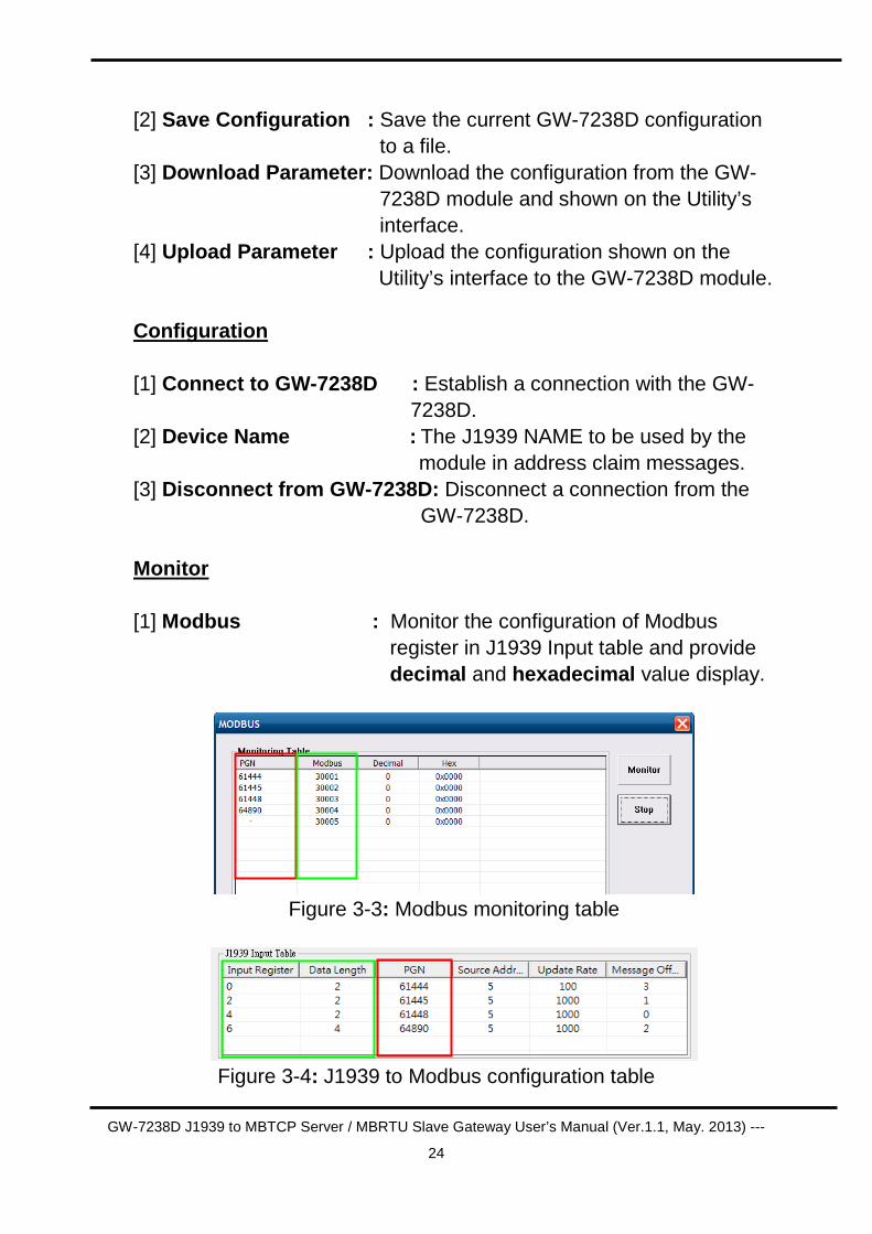
[1] Modbus : Monitor the configuration of Modbus
register in J1939 Input table and provide decimal and hexadecimal value display.
Figure 3-3: Modbus monitoring table
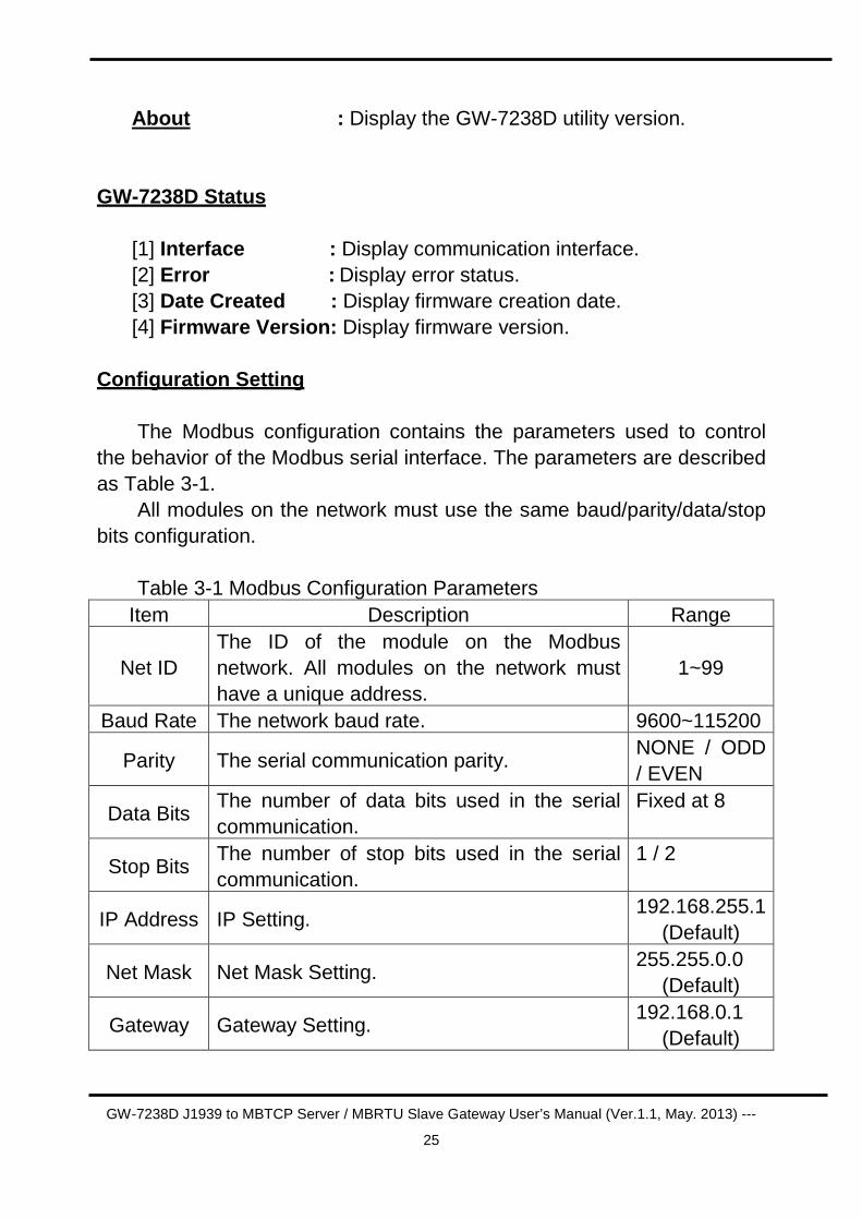
Figure 3-4: J1939 to Modbus configuration table
GW-7238D J1939 to MBTCP Server / MBRTU Slave Gateway User’s Manual (Ver.1.1, May. 2013) ---
25
About : Display the GW-7238D utility version.
GW-7238D Status [1] Interface : Display communication interface. [2] Error : Display error status. [3] Date Created : Display firmware creation date. [4] Firmware Version: Display firmware version.
Configuration Setting
The Modbus configuration contains the parameters used to control the behavior of the Modbus serial interface. The parameters are described as Table 3-1.
All modules on the network must use the same baud/parity/data/stop bits configuration.
Table 3-1 Modbus Configuration Parameters
Item Description Range
Net ID The ID of the module on the Modbus network. All modules on the network must have a unique address.
1~99
Baud Rate The network baud rate. 9600~115200
Parity The serial communication parity. NONE / ODD / EVEN
Data Bits The number of data bits used in the serial communication.
Fixed at 8
Stop Bits The number of stop bits used in the serial communication.
1 / 2
IP Address IP Setting. 192.168.255.1
(Default)
Net Mask Net Mask Setting. 255.255.0.0
(Default)
Gateway Gateway Setting. 192.168.0.1
(Default)
GW-7238D J1939 to MBTCP Server / MBRTU Slave Gateway User’s Manual (Ver.1.1, May. 2013) ---
26
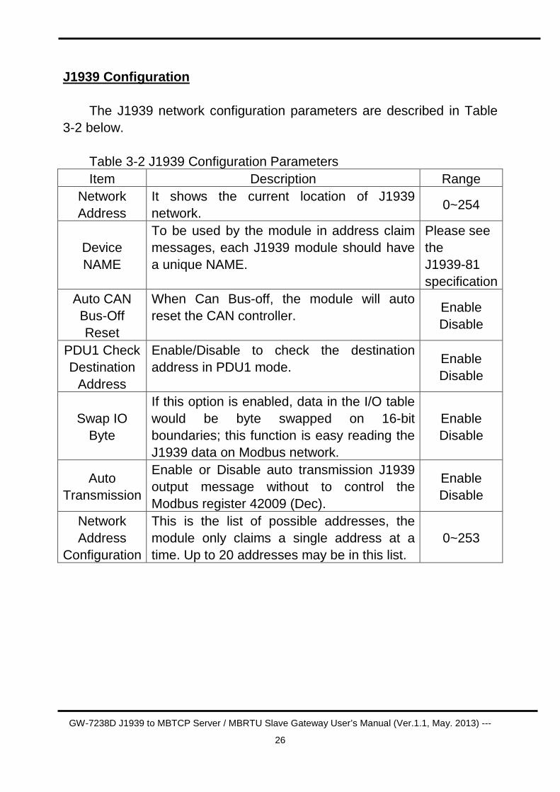
J1939 Configuration
The J1939 network configuration parameters are described in Table 3-2 below.
Table 3-2 J1939 Configuration Parameters Item Description Range
Network Address
It shows the current location of J1939 network.
0~254
Device NAME
To be used by the module in address claim messages, each J1939 module should have a unique NAME.
Please see the J1939-81 specification
Auto CAN Bus-Off Reset
When Can Bus-off, the module will auto reset the CAN controller.
Enable Disable
PDU1 Check Destination
Address
Enable/Disable to check the destination address in PDU1 mode.
Enable Disable
Swap IO Byte
If this option is enabled, data in the I/O table would be byte swapped on 16-bit boundaries; this function is easy reading the J1939 data on Modbus network.
Enable Disable
Auto Transmission
Enable or Disable auto transmission J1939 output message without to control the Modbus register 42009 (Dec).
Enable Disable
Network Address
Configuration
This is the list of possible addresses, the module only claims a single address at a time. Up to 20 addresses may be in this list.
0~253
GW-7238D J1939 to MBTCP Server / MBRTU Slave Gateway User’s Manual (Ver.1.1, May. 2013) ---
27
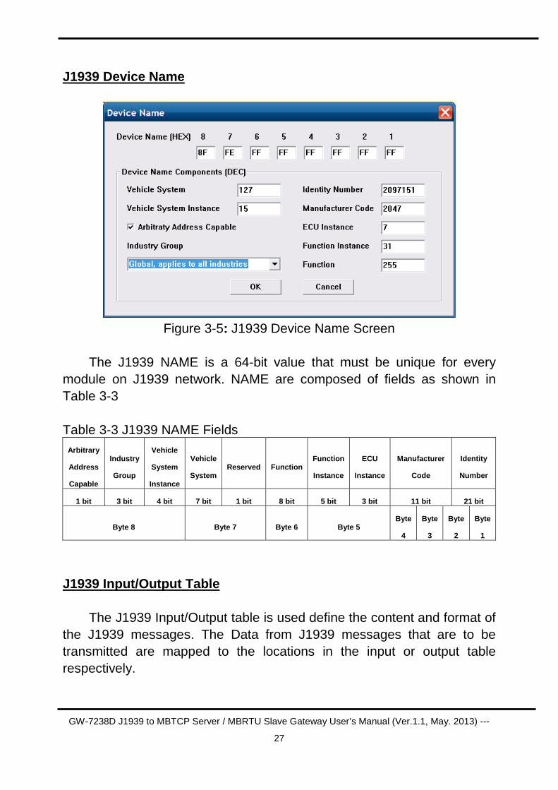
J1939 Device Name
Figure 3-5: J1939 Device Name Screen
The J1939 NAME is a 64-bit value that must be unique for every
module on J1939 network. NAME are composed of fields as shown in Table 3-3
Table 3-3 J1939 NAME Fields
Arbitrary
Address
Capable
Industry
Group
Vehicle
System
Instance
Vehicle
System Reserved Function
Function
Instance
ECU
Instance
Manufacturer
Code
Identity
Number
1 bit 3 bit 4 bit 7 bit 1 bit 8 bit 5 bit 3 bit 11 bit 21 bit
Byte 8 Byte 7 Byte 6 Byte 5 Byte
4
Byte
3
Byte
2
Byte
1
J1939 Input/Output Table The J1939 Input/Output table is used define the content and format of
the J1939 messages. The Data from J1939 messages that are to be transmitted are mapped to the locations in the input or output table respectively.
GW-7238D J1939 to MBTCP Server / MBRTU Slave Gateway User’s Manual (Ver.1.1, May. 2013) ---
28
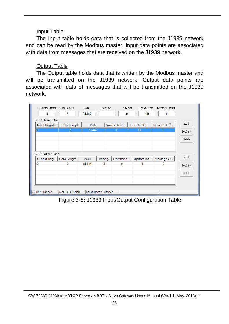
Input Table The Input table holds data that is collected from the J1939 network
and can be read by the Modbus master. Input data points are associated with data from messages that are received on the J1939 network.
Output Table The Output table holds data that is written by the Modbus master and
will be transmitted on the J1939 network. Output data points are associated with data of messages that will be transmitted on the J1939 network.
Figure 3-6: J1939 Input/Output Configuration Table
GW-7238D J1939 to MBTCP Server / MBRTU Slave Gateway User’s Manual (Ver.1.1, May. 2013) ---
29
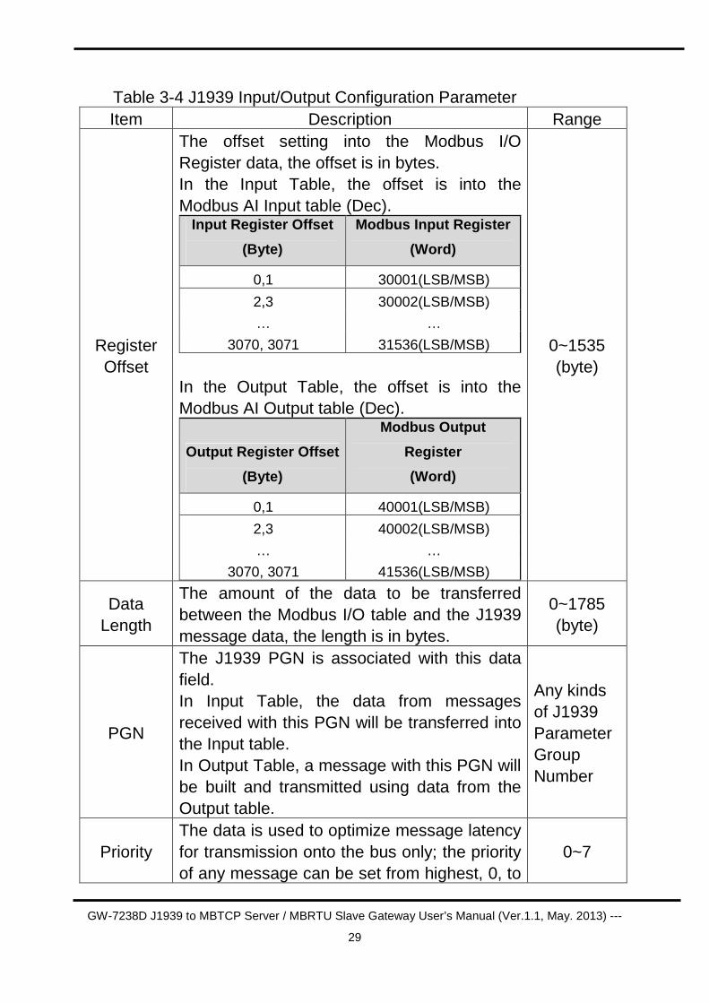
Table 3-4 J1939 Input/Output Configuration Parameter Item Description Range
Register Offset
The offset setting into the Modbus I/O Register data, the offset is in bytes. In the Input Table, the offset is into the Modbus AI Input table (Dec).
Input Register Offset
(Byte)
Modbus Input Register
(Word)
0,1 30001(LSB/MSB)
2,3 30002(LSB/MSB)
… …
3070, 3071 31536(LSB/MSB)
In the Output Table, the offset is into the Modbus AI Output table (Dec).
Output Register Offset
(Byte)
Modbus Output
Register
(Word)
0,1 40001(LSB/MSB)
2,3 40002(LSB/MSB)
… …
3070, 3071 41536(LSB/MSB)
0~1535 (byte)
Data Length
The amount of the data to be transferred between the Modbus I/O table and the J1939 message data, the length is in bytes.
0~1785 (byte)
PGN
The J1939 PGN is associated with this data field. In Input Table, the data from messages received with this PGN will be transferred into the Input table. In Output Table, a message with this PGN will be built and transmitted using data from the Output table.
Any kinds of J1939 Parameter Group Number
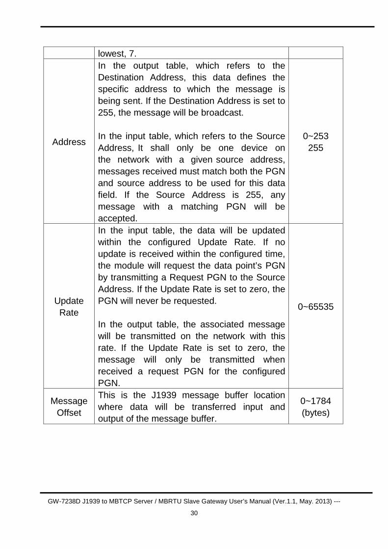
Priority The data is used to optimize message latency for transmission onto the bus only; the priority of any message can be set from highest, 0, to
0~7
GW-7238D J1939 to MBTCP Server / MBRTU Slave Gateway User’s Manual (Ver.1.1, May. 2013) ---
30
lowest, 7.
Address
In the output table, which refers to the Destination Address, this data defines the specific address to which the message is being sent. If the Destination Address is set to 255, the message will be broadcast. In the input table, which refers to the Source Address, It shall only be one device on the network with a given source address, messages received must match both the PGN and source address to be used for this data field. If the Source Address is 255, any message with a matching PGN will be accepted.
0~253 255
Update Rate
In the input table, the data will be updated within the configured Update Rate. If no update is received within the configured time, the module will request the data point’s PGN by transmitting a Request PGN to the Source Address. If the Update Rate is set to zero, the PGN will never be requested. In the output table, the associated message will be transmitted on the network with this rate. If the Update Rate is set to zero, the message will only be transmitted when received a request PGN for the configured PGN.
0~65535
Message Offset
This is the J1939 message buffer location where data will be transferred input and output of the message buffer.
0~1784 (bytes)
GW-7238D J1939 to MBTCP Server / MBRTU Slave Gateway User’s Manual (Ver.1.1, May. 2013) ---
31
4. Communication Network
4.1 Modbus Network
The GW-7238D, J1939 to Modbus Interface, supports the Modbus RTU serial protocol. It plays a Modbus slave on the network.
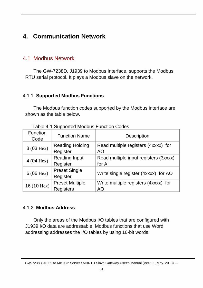
4.1.1 Supported Modbus Functions The Modbus function codes supported by the Modbus interface are
shown as the table below. Table 4-1 Supported Modbus Function Codes
Function Code
Function Name Description
3 (03 Hex) Reading Holding Register
Read multiple registers (4xxxx) for AO
4 (04 Hex) Reading Input Register
Read multiple input registers (3xxxx) for AI
6 (06 Hex) Preset Single Register
Write single register (4xxxx) for AO
16 (10 Hex) Preset Multiple Registers
Write multiple registers (4xxxx) for AO
4.1.2 Modbus Address
Only the areas of the Modbus I/O tables that are configured with J1939 I/O data are addressable, Modbus functions that use Word addressing addresses the I/O tables by using 16-bit words.
GW-7238D J1939 to MBTCP Server / MBRTU Slave Gateway User’s Manual (Ver.1.1, May. 2013) ---
32
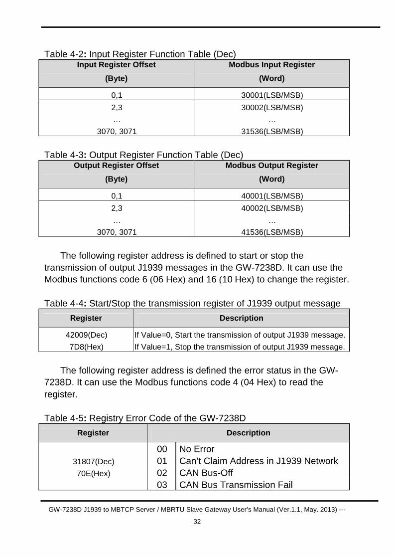
Table 4-2: Input Register Function Table (Dec) Input Register Offset
(Byte)
Modbus Input Register
(Word)
0,1 30001(LSB/MSB)
2,3 30002(LSB/MSB)
… …
3070, 3071 31536(LSB/MSB)
Table 4-3: Output Register Function Table (Dec)
Output Register Offset
(Byte)
Modbus Output Register
(Word)
0,1 40001(LSB/MSB)
2,3 40002(LSB/MSB)
… …
3070, 3071 41536(LSB/MSB)
The following register address is defined to start or stop the
transmission of output J1939 messages in the GW-7238D. It can use the Modbus functions code 6 (06 Hex) and 16 (10 Hex) to change the register. Table 4-4: Start/Stop the transmission register of J1939 output message
Register Description
42009(Dec)
7D8(Hex)
If Value=0, Start the transmission of output J1939 message.
If Value=1, Stop the transmission of output J1939 message.
The following register address is defined the error status in the GW-
7238D. It can use the Modbus functions code 4 (04 Hex) to read the register. Table 4-5: Registry Error Code of the GW-7238D
Register Description
00 No Error 01 Can’t Claim Address in J1939 Network 02 CAN Bus-Off
31807(Dec)
70E(Hex)
03 CAN Bus Transmission Fail
GW-7238D J1939 to MBTCP Server / MBRTU Slave Gateway User’s Manual (Ver.1.1, May. 2013) ---
33
4.2 J1939 Network J1939 is a higher-layer protocol based on Controller Area Network
(CAN). It provides serial data communications between microprocessor systems (also called Electronic Control Units - ECU) in any kind of heavy duty vehicles. The messages exchanged between these units can be data such as vehicle road speed, torque control message from the transmission to the engine, oil temperature, and many more.
4.2.1 Communication Methods
The GW-7238D provides two communication methods of SAE J1939, each serving a specific purpose.
Destination Specific Communications Destination specific communications use PDU1, but also the global
destination address 255. There are cases where this method will require the utilization of destination specific Parameter Group Numbers, for instance, in the case of more than one engine. A torque message, for example, must be sent only to the desired engine and not to both.
Broadcast Communications Broadcast communications use PDU2 and, as the name implies, they
can include: Sending a message from a single or multiple sources to a single destination; sending a message from a single or multiple sources to multiple destinations.
4.2.2 Parameter Groups Parameters groups are, for instance, engine temperature which
includes coolant temperature, fuel temperature, oil temperature, etc. The Parameter Groups (PG) architecture and Parameter Group Numbers (PGN) are described in SAE J1939/21 and defined in SAE J1939/71.
GW-7238D J1939 to MBTCP Server / MBRTU Slave Gateway User’s Manual (Ver.1.1, May. 2013) ---
34
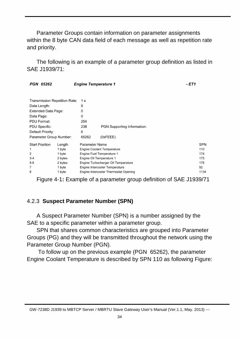
Parameter Groups contain information on parameter assignments within the 8 byte CAN data field of each message as well as repetition rate and priority.
The following is an example of a parameter group definition as listed in
SAE J1939/71:
Figure 4-1: Example of a parameter group definition of SAE J1939/71
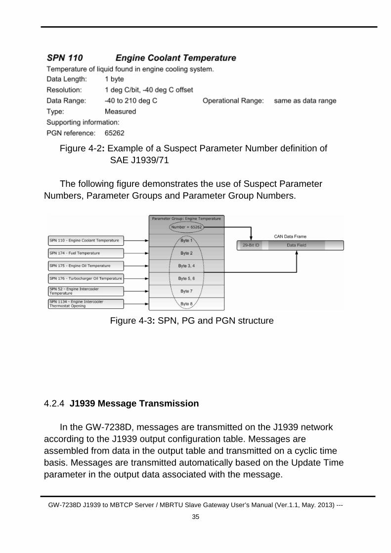
4.2.3 Suspect Parameter Number (SPN) A Suspect Parameter Number (SPN) is a number assigned by the
SAE to a specific parameter within a parameter group. SPN that shares common characteristics are grouped into Parameter
Groups (PG) and they will be transmitted throughout the network using the Parameter Group Number (PGN).
To follow up on the previous example (PGN 65262), the parameter Engine Coolant Temperature is described by SPN 110 as following Figure:
GW-7238D J1939 to MBTCP Server / MBRTU Slave Gateway User’s Manual (Ver.1.1, May. 2013) ---
35
Figure 4-2: Example of a Suspect Parameter Number definition of
SAE J1939/71 The following figure demonstrates the use of Suspect Parameter
Numbers, Parameter Groups and Parameter Group Numbers.
Figure 4-3: SPN, PG and PGN structure
4.2.4 J1939 Message Transmission In the GW-7238D, messages are transmitted on the J1939 network
according to the J1939 output configuration table. Messages are assembled from data in the output table and transmitted on a cyclic time basis. Messages are transmitted automatically based on the Update Time parameter in the output data associated with the message.
GW-7238D J1939 to MBTCP Server / MBRTU Slave Gateway User’s Manual (Ver.1.1, May. 2013) ---
36
4.2.5 J1939 Receiving Messages Input data points are combined according to PGN and Target Address.
If the Target Address is configured as 255, all messages with a matching PGN will be parsed using the data point, regardless of source address. If the Target Address is not 255, received messages must match both the PGN and source address in order to be handled by the input data point.
4.2.6 Transport Protocol for Large Messages Transmission and Reception of Large Messages Messages with buffer sizes of 8 bytes or less can be directly sent and
received on J1939. However, messages with buffer sizes greater than 8 bytes must be fragmented, transmitted, and reassembled using the J1939 transport protocol.
Users should reference the J1939-21 specification. It provides the description of when and how the transport protocol is used by the GW-7238D.
GW-7238D now provides a BAM (Broadcast Announce Message)
mechanism, when messages larger than 8 bytes in length and the destination address is 255, the message will be sent or receive using transport protocol BAM.

GW-7238D J1939 to MBTCP Server / MBRTU Slave Gateway User’s Manual (Ver.1.1, May. 2013) ---
37
5. Application
Control systems such as PAC, PLC and PC on Modbus network require some data that is collected by an ECU such as engine on J1939 network. There is also a part of data that is determined by the system controller and transmitted through the Modbus network for the ECU to the J1939 network.
Figure 5-1: Network application structure
5.1 Hardware Installation Users may need to make some hardware settings before the
application. The detailed illustration is as below: Step1: Check GW-7238D Firmware Mode
In operation mode, users can use the Modbus Master command to
send and receive J1939 messages via the GW-7238D Users need to set the dip-switch to the “Normal” position as Figure 5-2
and reset the power, and that the GW-7238D can run in the operation mode.
GW-7238D J1939 to MBTCP Server / MBRTU Slave Gateway User’s Manual (Ver.1.1, May. 2013) ---
38
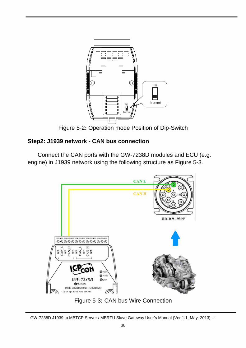
Figure 5-2: Operation mode Position of Dip-Switch
Step2: J1939 network - CAN bus connection
Connect the CAN ports with the GW-7238D modules and ECU (e.g. engine) in J1939 network using the following structure as Figure 5-3.
Figure 5-3: CAN bus Wire Connection
GW-7238D J1939 to MBTCP Server / MBRTU Slave Gateway User’s Manual (Ver.1.1, May. 2013) ---
39
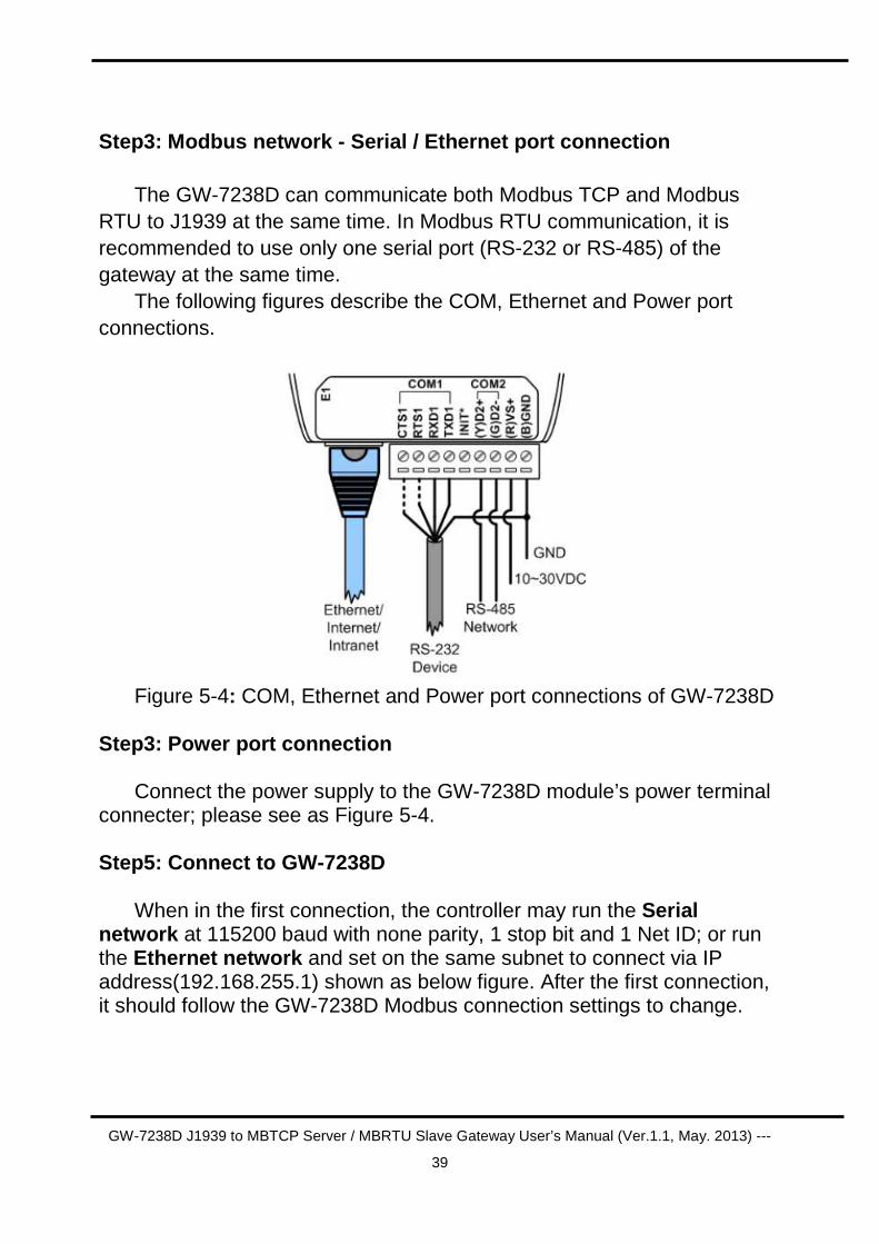
Step3: Modbus network - Serial / Ethernet port conn ection
The GW-7238D can communicate both Modbus TCP and Modbus
RTU to J1939 at the same time. In Modbus RTU communication, it is recommended to use only one serial port (RS-232 or RS-485) of the gateway at the same time.
The following figures describe the COM, Ethernet and Power port connections.
Figure 5-4: COM, Ethernet and Power port connections of GW-7238D
Step3: Power port connection
Connect the power supply to the GW-7238D module’s power terminal connecter; please see as Figure 5-4.
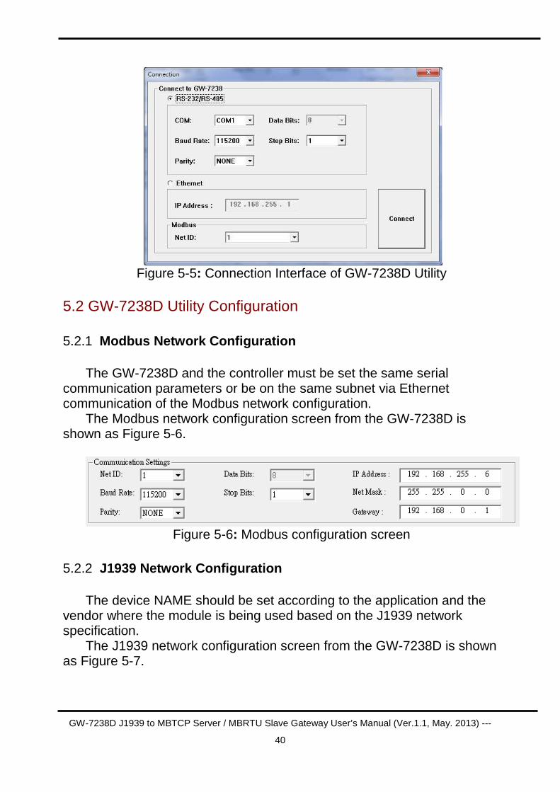
Step5: Connect to GW-7238D
When in the first connection, the controller may run the Serial network at 115200 baud with none parity, 1 stop bit and 1 Net ID; or run the Ethernet network and set on the same subnet to connect via IP address(192.168.255.1) shown as below figure. After the first connection, it should follow the GW-7238D Modbus connection settings to change.
GW-7238D J1939 to MBTCP Server / MBRTU Slave Gateway User’s Manual (Ver.1.1, May. 2013) ---
40
Figure 5-5: Connection Interface of GW-7238D Utility
5.2 GW-7238D Utility Configuration
5.2.1 Modbus Network Configuration
The GW-7238D and the controller must be set the same serial communication parameters or be on the same subnet via Ethernet communication of the Modbus network configuration.
The Modbus network configuration screen from the GW-7238D is shown as Figure 5-6.
Figure 5-6: Modbus configuration screen
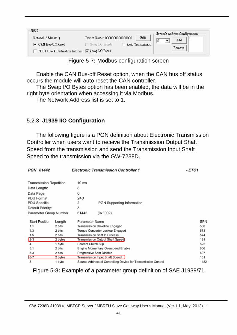
5.2.2 J1939 Network Configuration
The device NAME should be set according to the application and the vendor where the module is being used based on the J1939 network specification.
The J1939 network configuration screen from the GW-7238D is shown as Figure 5-7.
GW-7238D J1939 to MBTCP Server / MBRTU Slave Gateway User’s Manual (Ver.1.1, May. 2013) ---
41
Figure 5-7: Modbus configuration screen
Enable the CAN Bus-off Reset option, when the CAN bus off status
occurs the module will auto reset the CAN controller. The Swap I/O Bytes option has been enabled, the data will be in the
right byte orientation when accessing it via Modbus. The Network Address list is set to 1.
5.2.3 J1939 I/O Configuration
The following figure is a PGN definition about Electronic Transmission Controller when users want to receive the Transmission Output Shaft Speed from the transmission and send the Transmission Input Shaft Speed to the transmission via the GW-7238D.
Figure 5-8: Example of a parameter group definition of SAE J1939/71
GW-7238D J1939 to MBTCP Server / MBRTU Slave Gateway User’s Manual (Ver.1.1, May. 2013) ---
42
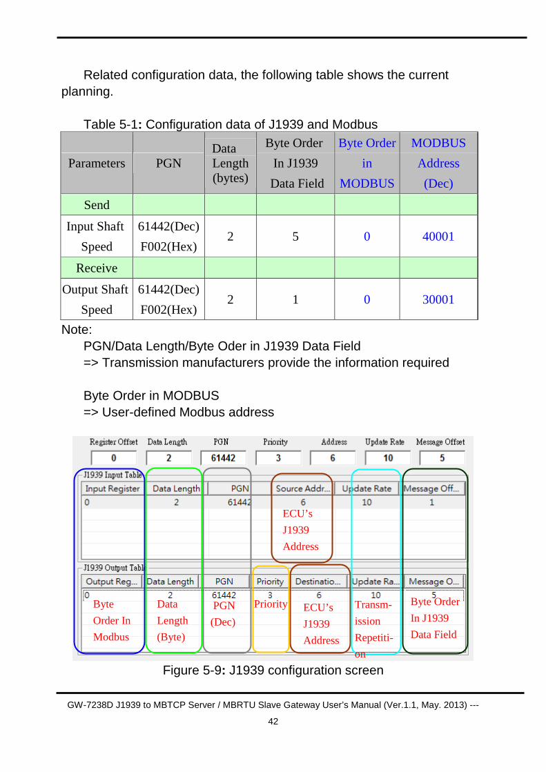
Related configuration data, the following table shows the current planning.
Table 5-1: Configuration data of J1939 and Modbus
Parameters PGN Data Length (bytes)
Byte Order
In J1939
Data Field
Byte Order
in
MODBUS
MODBUS
Address
(Dec)
Send
Input Shaft
Speed
61442(Dec)
F002(Hex) 2 5 0 40001
Receive
Output Shaft
Speed
61442(Dec)
F002(Hex) 2 1 0 30001
Note: PGN/Data Length/Byte Oder in J1939 Data Field => Transmission manufacturers provide the information required
Byte Order in MODBUS => User-defined Modbus address
Figure 5-9: J1939 configuration screen
Byte
Order In
Modbus
Data
Length
(Byte)
PGN
(Dec)
Priority
ECU’s
J1939
Address
ECU’s
J1939
Address
Transm-
ission
Repetiti-
on
Byte Order
In J1939
Data Field
GW-7238D J1939 to MBTCP Server / MBRTU Slave Gateway User’s Manual (Ver.1.1, May. 2013) ---
43
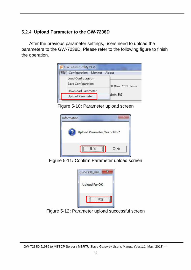
5.2.4 Upload Parameter to the GW-7238D After the previous parameter settings, users need to upload the
parameters to the GW-7238D. Please refer to the following figure to finish the operation.
Figure 5-10: Parameter upload screen
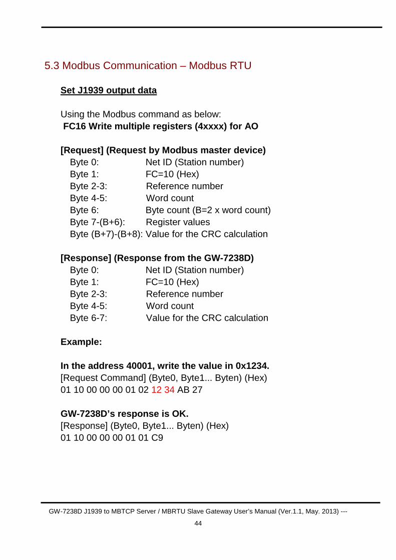
Figure 5-11: Confirm Parameter upload screen
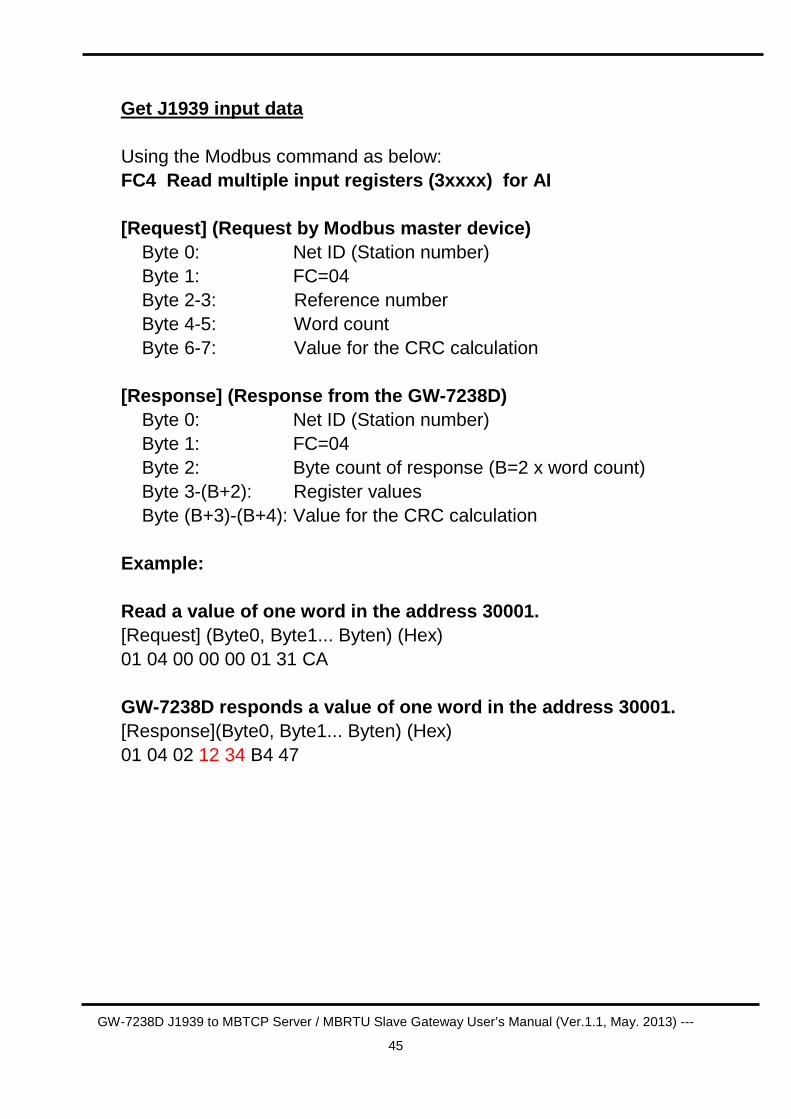
Figure 5-12: Parameter upload successful screen
GW-7238D J1939 to MBTCP Server / MBRTU Slave Gateway User’s Manual (Ver.1.1, May. 2013) ---
44
5.3 Modbus Communication – Modbus RTU
Set J1939 output data
Using the Modbus command as below: FC16 Write multiple registers (4xxxx) for AO [Request] (Request by Modbus master device)
Byte 0: Net ID (Station number) Byte 1: FC=10 (Hex) Byte 2-3: Reference number Byte 4-5: Word count Byte 6: Byte count (B=2 x word count) Byte 7-(B+6): Register values Byte (B+7)-(B+8): Value for the CRC calculation
[Response] (Response from the GW-7238D)
Byte 0: Net ID (Station number) Byte 1: FC=10 (Hex) Byte 2-3: Reference number Byte 4-5: Word count Byte 6-7: Value for the CRC calculation
Example: In the address 40001, write the value in 0x1234. [Request Command] (Byte0, Byte1... Byten) (Hex) 01 10 00 00 00 01 02 12 34 AB 27 GW-7238D’s response is OK. [Response] (Byte0, Byte1... Byten) (Hex) 01 10 00 00 00 01 01 C9
GW-7238D J1939 to MBTCP Server / MBRTU Slave Gateway User’s Manual (Ver.1.1, May. 2013) ---
45
Get J1939 input data Using the Modbus command as below: FC4 Read multiple input registers (3xxxx) for AI
[Request] (Request by Modbus master device) Byte 0: Net ID (Station number) Byte 1: FC=04 Byte 2-3: Reference number Byte 4-5: Word count Byte 6-7: Value for the CRC calculation [Response] (Response from the GW-7238D) Byte 0: Net ID (Station number) Byte 1: FC=04 Byte 2: Byte count of response (B=2 x word count) Byte 3-(B+2): Register values Byte (B+3)-(B+4): Value for the CRC calculation Example: Read a value of one word in the address 30001. [Request] (Byte0, Byte1... Byten) (Hex) 01 04 00 00 00 01 31 CA GW-7238D responds a value of one word in the addres s 30001. [Response](Byte0, Byte1... Byten) (Hex) 01 04 02 12 34 B4 47
GW-7238D J1939 to MBTCP Server / MBRTU Slave Gateway User’s Manual (Ver.1.1, May. 2013) ---
46
Start or Stop sending J1939 output message Using the Modbus command as below: FC6 Write single register (4xxxx) for AO [Request] (Request by Modbus master device)
Byte 0: Net ID (Station number) Byte 1: FC=06 (Hex) Byte 2-3: Reference number Byte 4-5: Register value Byte 6-7 Value for the CRC calculation
[Response] (Response from the GW-7238D)
Byte 0: Net ID (Station number) Byte 1: FC=06 (Hex) Byte 2-3: Reference number Byte 4-5: Register value Byte 6-7 Value for the CRC calculation
Example: Start sending J1939 output message In the address 42009, write the value in 0x00. [Request Command] (Byte0, Byte1... Byten) (Hex) 01 06 07 D8 00 00 08 85 GW-7238D responds the register value. [Response] (Byte0, Byte1... Byten) (Hex) 01 06 07 D8 00 00 08 85 Example: Stop sending J1939 output message In the address 42009, write the value in 0x01. [Request Command] (Byte0, Byte1... Byten) (Hex) 01 06 07 D8 00 01 C9 45 GW-7238D responds the register value. [Response] (Byte0, Byte1... Byten) (Hex) 01 06 07 D8 00 01 C9 45
GW-7238D J1939 to MBTCP Server / MBRTU Slave Gateway User’s Manual (Ver.1.1, May. 2013) ---
47
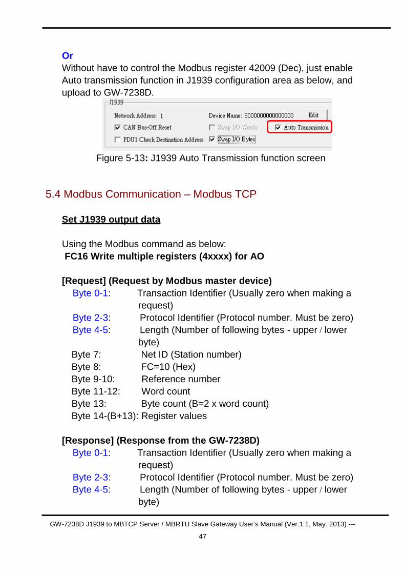
Or Without have to control the Modbus register 42009 (Dec), just enable Auto transmission function in J1939 configuration area as below, and upload to GW-7238D.
Figure 5-13: J1939 Auto Transmission function screen
5.4 Modbus Communication – Modbus TCP
Set J1939 output data
Using the Modbus command as below: FC16 Write multiple registers (4xxxx) for AO [Request] (Request by Modbus master device) Byte 0-1: Transaction Identifier (Usually zero when making a
request) Byte 2-3: Protocol Identifier (Protocol number. Must be zero) Byte 4-5: Length (Number of following bytes - upper / lower
byte) Byte 7: Net ID (Station number) Byte 8: FC=10 (Hex) Byte 9-10: Reference number Byte 11-12: Word count Byte 13: Byte count (B=2 x word count) Byte 14-(B+13): Register values
[Response] (Response from the GW-7238D) Byte 0-1: Transaction Identifier (Usually zero when making a
request) Byte 2-3: Protocol Identifier (Protocol number. Must be zero) Byte 4-5: Length (Number of following bytes - upper / lower
byte)
GW-7238D J1939 to MBTCP Server / MBRTU Slave Gateway User’s Manual (Ver.1.1, May. 2013) ---
48
Byte 6: Net ID (Station number) Byte 7: FC=10 (Hex) Byte 8-9: Reference number Byte 10-11: Word count
Example: In the address 40001, write the value in 0x1234. [Request Command] (Byte0, Byte1... Byten) (Hex) 00 00 00 00 00 09 01 10 00 00 00 01 02 12 34 GW-7238D’s response is OK. [Response] (Byte0, Byte1... Byten) (Hex) 00 00 00 00 00 06 01 10 00 00 00 01 Get J1939 input data Using the Modbus command as below: FC4 Read multiple input registers (3xxxx) for AI
[Request] (Request by Modbus master device) Byte 0-1: Transaction Identifier (Usually zero when making a
request) Byte 2-3: Protocol Identifier (Protocol number. Must be zero) Byte 4-5: Length (Number of following bytes - upper / lower
byte) Byte 6: Net ID (Station number) Byte 7: FC=04 Byte 8-9: Reference number Byte 10-11: Word count [Response] (Response from the GW-7238D) Byte 0-1: Transaction Identifier (Usually zero when
making a request) Byte 2-3: Protocol Identifier (Protocol number. Must be
zero) Byte 4-5: Length (Number of following bytes - upper /
lower byte)
GW-7238D J1939 to MBTCP Server / MBRTU Slave Gateway User’s Manual (Ver.1.1, May. 2013) ---
49
Byte 6: Net ID (Station number) Byte 7: FC=04 Byte 8: Byte count of response (B=2 x word count) Byte 9-(B+8): Register values Example: Read a value of one word in the address 30001. [Request] (Byte0, Byte1... Byten) (Hex) 00 00 00 00 00 06 01 04 00 00 00 01 GW-7238D responds a value of one word in the addres s 30001. [Response](Byte0, Byte1... Byten) (Hex) 00 00 00 00 00 05 01 04 02 12 34 Start or Stop sending J1939 output message Using the Modbus command as below: FC6 Write single register (4xxxx) for AO [Request] (Request by Modbus master device) Byte 0-1: Transaction Identifier (Usually zero when making a
request) Byte 2-3: Protocol Identifier (Protocol number. Must be zero) Byte 4-5: Length (Number of following bytes - upper / lower
byte) Byte 6: Net ID (Station number) Byte 7: FC=06 (Hex) Byte 8-9: Reference number Byte 10-11: Register value
[Response] (Response from the GW-7238D) Byte 0-1: Transaction Identifier (Usually zero when making a
request) Byte 2-3: Protocol Identifier (Protocol number. Must be zero) Byte 4-5: Length (Number of following bytes - upper / lower
byte)
GW-7238D J1939 to MBTCP Server / MBRTU Slave Gateway User’s Manual (Ver.1.1, May. 2013) ---
50
Byte 6: Net ID (Station number) Byte 7: FC=06 (Hex) Byte 8-9: Reference number Byte 10-11: Register value
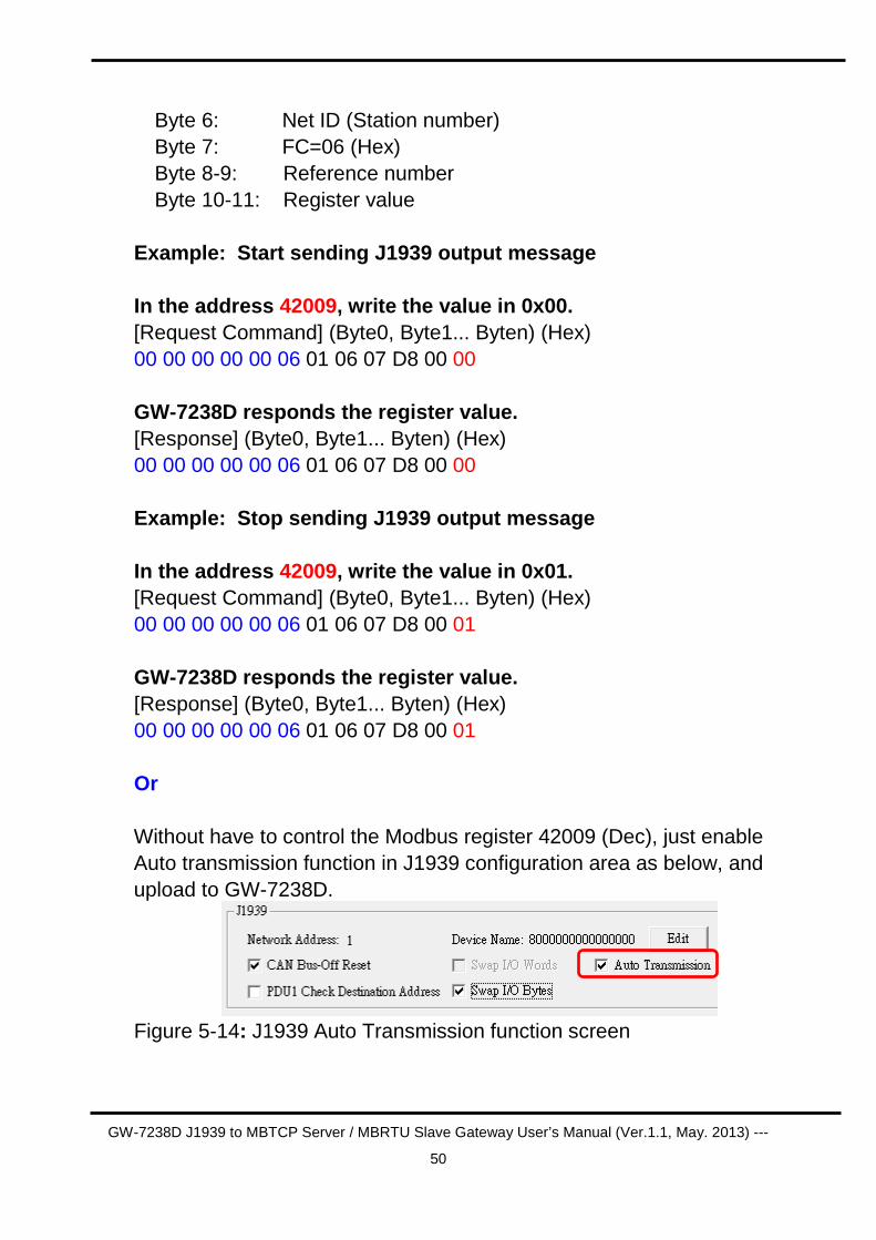
Example: Start sending J1939 output message In the address 42009, write the value in 0x00. [Request Command] (Byte0, Byte1... Byten) (Hex) 00 00 00 00 00 06 01 06 07 D8 00 00 GW-7238D responds the register value. [Response] (Byte0, Byte1... Byten) (Hex) 00 00 00 00 00 06 01 06 07 D8 00 00 Example: Stop sending J1939 output message In the address 42009, write the value in 0x01. [Request Command] (Byte0, Byte1... Byten) (Hex) 00 00 00 00 00 06 01 06 07 D8 00 01 GW-7238D responds the register value. [Response] (Byte0, Byte1... Byten) (Hex) 00 00 00 00 00 06 01 06 07 D8 00 01 Or Without have to control the Modbus register 42009 (Dec), just enable Auto transmission function in J1939 configuration area as below, and upload to GW-7238D.
Figure 5-14: J1939 Auto Transmission function screen
GW-7238D J1939 to MBTCP Server / MBRTU Slave Gateway User’s Manual (Ver.1.1, May. 2013) ---
51
6. Troubleshooting
Item Trouble state Solution
1 CAN Bus Transmission Fail (Power LED Blink per 100 ms)
Make sure the CAN bus wiring is connected, and connected to the correct pin.
2 CAN Bus-Off (Power LED Blink per 500 ms)
Make sure the CAN bus wiring does not short-circuit
3 Can’t Claim Address in J1939 Network (Power LED Blink per 1000 ms)
Please configure another J1939 network address in GW-7238D Utility.
4
Can not transmit the output J1939 message
1. Make sure the Start/Stop sending J1939 output message register (42009) is 0x00.
2. Make sure the Update Rate of J1939 output message table is not zero.
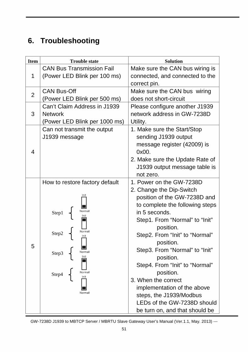
5
How to restore factory default
1. Power on the GW-7238D 2. Change the Dip-Switch
position of the GW-7238D and to complete the following steps in 5 seconds. Step1. From “Normal” to “Init”
position. Step2. From “Init” to “Normal”
position. Step3. From “Normal” to “Init”
position. Step4. From “Init” to “Normal”
position. 3. When the correct
implementation of the above steps, the J1939/Modbus LEDs of the GW-7238D should be turn on, and that should be
Step1
Step2
Step3
Step4
GW-7238D J1939 to MBTCP Server / MBRTU Slave Gateway User’s Manual (Ver.1.1, May. 2013) ---
52
turn off after 500 ms later. 4. Reset the power of the GW-
7238D, and the GW-7238D would back to factory defaults.
6. Reconnect the GW-7238D by using the serial network setting as 115200 baud with none parity, 8 data bit, 1 stop bit and 1 Net ID; or run the Ethernet network and set on the same subnet to connect via IP address(192.168.255.1)
Recommended