Embed Size (px)
Citation preview
Grayhill Confidential Page 1 8/10/18
3K Gen 2.0 Keypad Modules
J1939/CAN
User Manual
Grayhill PN: 3KUM1980-1
Revisions
Revision Description Check / Approve A Original.
ECN#414854 JAA 4-24-2018 BMM/JLF 4-24-2018
N/A
Changed LED STATUS PGNS to PROP B Updated names of LOW POWER CONFIG parameters Minor updates to LOW POWER configuration and power up operation.
N/A
N/A Updated descriptions of modes of operation. Removed Partial Wake mode. JLF 7/25/2018
B Minor formatting and corrections. ECN# 415595 JLF 8/10/2018
JAA/BMM 8/10/2018
10/18/18
Grayhill Confidential Page 2 8/10/18
Table of Contents 1. Overview .................................................................................................................................... 4
1.1. Reference Documents ....................................................................................................... 4 2. Keypad Operation ...................................................................................................................... 4
2.1. Modes of Operation ............................................................................................................ 5 2.1.1. Initial Power-Up ........................................................................................................... 5 2.1.2. Low Power .................................................................................................................. 5 2.1.3. Wake ........................................................................................................................... 5 2.1.4. Run .............................................................................................................................. 6 Demo Mode ........................................................................................................................ 7 2.1.5. .......................................................................................................................................... 7
2.2. CAN FD Tolerant Feature .................................................................................................. 8 3. Diagnostics ................................................................................................................................ 8
3.1. Key Diagnostics .................................................................................................................. 8 3.2. LED Indicator Diagnostics .................................................................................................. 8
4. Keypad Configuration ................................................................................................................ 9 4.1. Reading .............................................................................................................................. 9
4.1.1. Example ...................................................................................................................... 9 4.2. Writing ................................................................................................................................ 9
4.2.1. Example ...................................................................................................................... 9 4.3. Parameter List .................................................................................................................... 9
4.3.1. ECUID Part Number ID=0x00,Size <= 64 ............................................................... 9 4.3.2. ECUID Location ID=0x01,Size <= 64 .................................................................... 10 4.3.3. ECUID Type ID=0x02, Size<= 64 ........................................................................ 10 4.3.4. ECUID Manufacturer ID=0x03, Size<= 64 ............................................................. 10 4.3.5. Component ID Make ID=0x04, Size <=5 ............................................................... 10 4.3.6. Component ID Model ID=0x05, Size<= 64 ............................................................ 10 4.3.7. Component ID Serial Number ID=0x06, Size<= 64 ................................................ 10 4.3.9. J1939 Name Identification ID=0x08, Size = 4 ........................................................ 10 4.3.11. J1939 Name ECU Instance ID=0x0A, Size = 1 ................................................... 10 4.3.13. J1939 Name Function ID=0x0C, Size = 1 .......................................................... 10 4.3.14. J1939 Name Vehicle System ID=0x0D, Size = 1 ................................................ 11 4.3.16. J1939 Name Industry Group ID=0x0F, Size = 1.................................................. 11 4.3.17. J1939 Name Arbitrary Address Capable ID=0x10, Size = 1 ................................. 11 4.3.18. Button PGN ID=0x11, Size = 4 ......................................................................... 11 4.3.19. Button Priority ID=0x12, Size = 1 ....................................................................... 11 4.3.21. Button Transmit Period ID=0x14, Size = 1 ......................................................... 11 4.3.22. Indicator Status 1 PGN ID=0x15, Size = 4 ......................................................... 11 4.3.23. Indicator Status 2 PGN ID=0x16, Size = 4 ......................................................... 11 4.3.24. Indicator Status PRI ID=0x17, Size = 1 .............................................................. 12 4.3.25. Indicator Status Send On Event ID=0x18, Size = 1 ............................................. 12 4.3.26. Indicator Status Transmit Period ID=0x19, Size = 1 ........................................... 12 4.3.27. Diagnostic Blink Period ID=0x1A, Size = 1 ......................................................... 12 4.3.28. LED COMM Timeout Period ID=0x1B, Size = 1 .................................................. 12 4.3.29. LED Stuffing Configuration 1 ID=0x1C, Size = 3 ................................................. 12 4.3.30. LED Stuffing Configuration 2 ID=0x1D, Size = 3 ................................................. 12 4.3.31. Default Indicator Intensity ID=0x1E, Size = 1 ..................................................... 12 4.3.32. Default Backlight Intensity ID=0x1F, Size = 1 ..................................................... 13 4.3.33. Stuck Button Error Timeout Period ID=0x20, Size = 1 ......................................... 13 4.3.34. LED PWM BASE 1 ID=0x21, Size = 24 ............................................................ 13 4.3.35. LED IREF BASE 1 ID=0x22, Size = 24 ............................................................. 13 4.3.36. LED PWM BASE 2 ID=0x23, Size = 24 ............................................................ 13 4.3.37. LED IREF BASE 2 ID=0x24, Size = 24 ............................................................. 13 4.3.38. DEVICE CONFIG ID=0x25, Size = 2 ................................................................. 13
10/18/18
Grayhill Confidential Page 3 8/10/18
4.3.39. FLEXIO CONFIG ID=0x26, Size = 1 ................................................................. 13 4.3.40. Demo Mode ID=0x27, Size = 1 ........................................................................ 14 4.3.41. Baud Rate ID=0x28, Size=1 ............................................................................. 14 4.3.42. AUXIO1 Priority ID=0x29, Size=1 ...................................................................... 14 4.3.43. AUXIO1 Send On Event ID=0x2A, Size=1 ......................................................... 14 4.3.44. AUXIO1 Tx Period ID=0x2B, Size=1 ................................................................. 14 4.3.45. LOW_POWER_DELAY_PER ID=0x2C, Size=1 ................................................. 14 4.3.46. LOW_POWER_WAKE_SIG_PER ID=0x2D, Size=1 .......................................... 15 4.3.47. LOW_POWER_CFG ID=0x2E, Size=1 ............................................................. 15 4.3.48. DIAG_REPORTING_CFG ID=0x2F, Size=1 ...................................................... 16 4.3.49. Source Address ID=0x30, Size=1 ..................................................................... 16 4.3.50. Source Address Save ID=0x31, Size=1 ............................................................. 16 4.3.51. Brightness Control Configuration ID=0x32, Size = 1 ............................................ 16
5. Communications ...................................................................................................................... 17 5.1. Message Header Description ........................................................................................... 17
5.1.1. Priority ....................................................................................................................... 17 5.1.2. DP (Data Page) ......................................................................................................... 17 5.1.3. Protocol Data Unit (PDU) - PDU Format (PF)........................................................... 17 5.1.4. Protocol Data Unit (PDU) - PDU Specific (PS) ......................................................... 17 5.1.5. Source Address ........................................................................................................ 17 5.1.6. Parameter Group Number ........................................................................................ 17
5.2. Bit-field Location and Byte Ordering ................................................................................. 18 5.3. Keypad Source Address ................................................................................................... 18 5.4. Physical Layer .................................................................................................................. 18 5.5. Standard PGNs ................................................................................................................ 19
5.5.1. AUXIO 1 (FlexIO Status) 65241 (0xFED9) ........................................................... 19 5.5.2. AUXIO 2 (Indicator Set 1) 42752 (0xA700) ............................................................ 20 5.5.3. AUXIO 3 (Indicator Set 2 ) 42496 (0xA600) .......................................................... 21 5.5.4. AUXIO 4 (FlexIO Control) 42240 (0xA500) ........................................................... 22 5.5.5. Cab Illumination 53248 (0xD000) ........................................................................ 22 5.5.6. Memory Access Request (DM14) 55552 (0xD900) ................................................ 22 5.5.7. Memory Access Response (DM15) 55296 (0xD800) ............................................. 22 5.5.8. Binary Data Transfer (DM16 ) 55040 (0xD700) ..................................................... 22 5.5.9. Boot Load Data (DM17) 54784 (0xD600) ............................................................ 22 5.5.10. Acknowledgement Message 59392 (0xE800) .................................................... 23 5.5.11. PGN Request 59904 (0xEA00) ........................................................................ 23 5.5.12. Transport Protocol Data Transfer 60160 (0xEB00) ............................................. 23 5.5.13. Transport Protocol Connection Mgmt 60416 (0xEC00) ...................................... 23 5.5.14. Address Claimed 60928 (0xEE00) ................................................................... 24 5.5.15. Prop A (Normal Mode) 61184 (0xEF00) .................................................. 25 5.5.16. Prop A (Configuration Mode*) 61184 (0xEF00) ................................................. 25 5.5.17. ECU Identification Information 64965 (0xFDC5) ................................................ 26 5.5.18. Active Diagnostic Trouble Codes (DM1) 65226 (0xFECA) ......................... 26 5.5.19. Previously Active Trouble Codes (DM2) 65226 (0xFECB) ........................... 26 5.5.20. Clear/Reset of Previously Active DTCs (DM3) 65227 (0xFECC) ....................... 27 5.5.21. Clear/Reset of Active DTCs (DM11) 65235 (0xFED3) ........................... 27 5.5.22. Commanded Address 65240 (0xFED8) ........................................................... 27 5.5.23. Software Identification 65242 (0xFEDA) ........................................................... 28 5.5.24. Component ID 65259 (0xFEEB) ........................................................................ 28 5.5.25. Prop B (Key Press Data Default PGN) 65282 (0xFF02) ...................................... 29 5.5.26. Prop B (Indicator Set 1 Status ) 65447 (0xFFA7) ............................................... 30 5.5.27. Prop B (Indicator Set 2 Status ) 65446 (0xFFA6) ............................................... 31
APPENDIX A Diagnostic Trouble Codes ........................................................................................ 32 APPENDIX B Device Configuration Parameters ............................................................................ 33
10/18/18
Grayhill Confidential Page 4 8/10/18
1. Overview This document describes the functionality and communication of the Grayhill CAN-Bus Keypads Gen 2.0. Modules must be programmed with 3KPR2021-2 v1.03 or later.
1.1. Reference Documents The following documents are referenced within this document.
o SAE-J1939 o SAE-J1939/11 o SAE-J1939/21 o SAE-J1939/71 o SAE-J1939/81 o ISO-11898-2
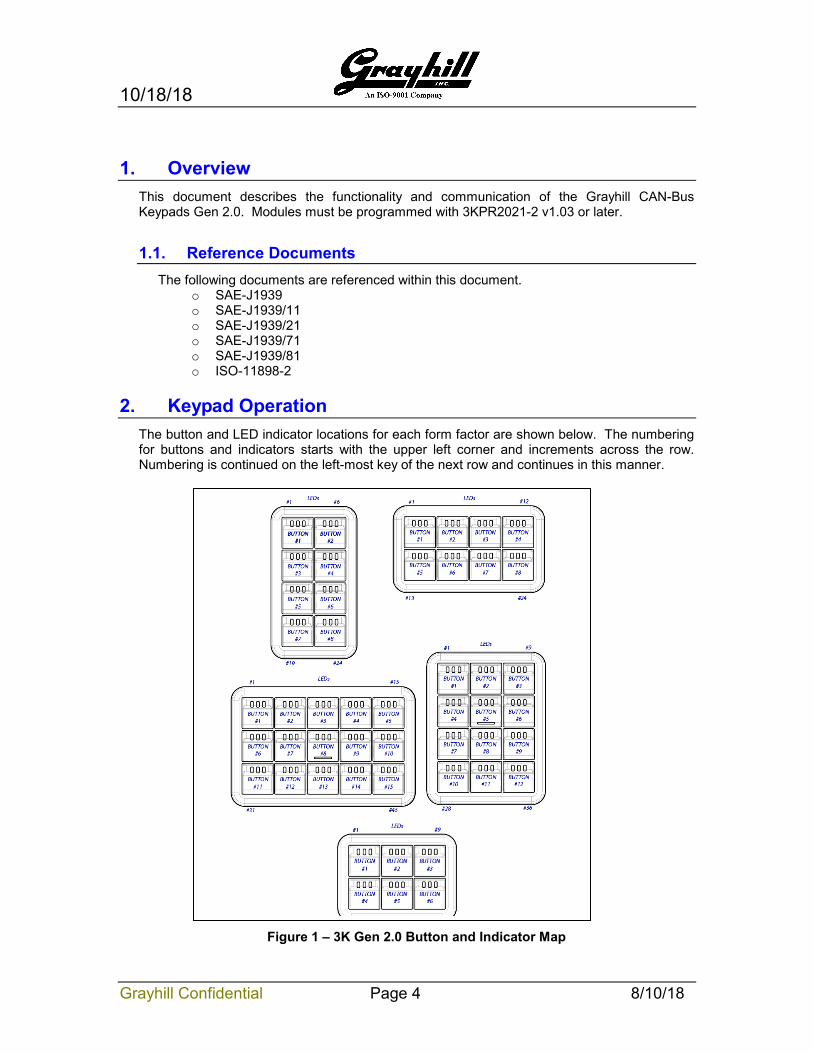
2. Keypad Operation The button and LED indicator locations for each form factor are shown below. The numbering for buttons and indicators starts with the upper left corner and increments across the row. Numbering is continued on the left-most key of the next row and continues in this manner.
Figure 1 – 3K Gen 2.0 Button and Indicator Map
10/18/18
Grayhill Confidential Page 5 8/10/18
2.1. Modes of Operation
2.1.1. Initial Power-Up This state is when the device is powered for the first time. When this state is entered (typically at 4V), all of the peripherals are initialized. The device remains in this state until the supply voltage reaches a minimum (typically 6.5V).
• Low Power Disabled: (LOW_POWER_CFG =0, 4) The device immediately enters Run mode. The FlexIO’s can be used as I/O.
• Low Power Enabled: (LOW_POWER_CFG =1, 2) The device immediately enters Low Power Mode.
2.1.2. Low Power When this state is entered, the device turns off all indicators and backlights and places all peripherals in low power mode. The device will enter wake mode with one of the following events:
• Button Press • CAN Traffic • FlexIO 2 goes active high (if configured)
2.1.3. Wake • If the device entered the low power mode from initial power-up then any wake
event will initiate the address claim procedure.
• LOW_POWER_CFG = 1: The FlexIO 1 is asserted to wake the ECU or other devices. Flex IO 1 remains on for the full LOW_POWER_WAKE_SIG_PER time. The device enters Run mode when FlexIO 2 is asserted. If the device entered the low power mode from run mode then only the FLEXIO2 wake event will initiate the address claim procedure.
• LOW_POWER_CFG = 2, The FlexIO 1 is asserted to wake the ECU or other devices. Flex IO 1 is de-asserted if FlexIO 2 is pulled high before the LOW_POWER_WAKE_SIG_PER time expires. The device enters Run mode when Flex IO 2 is asserted. If the device entered the low power mode from run mode then only the FLEXIO2 wake event will initiate the address claim procedure.
• LOW_POWER_CFG = 4: No IO is used. The device enters Run mode. If the device entered the low power mode from run mode then only the CAN traffic or button press wake event will initiate the address claim procedure.
10/18/18
Grayhill Confidential Page 6 8/10/18
2.1.4. Run Entering Run mode initiates the J1939 Address Claiming procedure as defined in section 2.1.3. If the keypad loses arbitration with another device having the same source address and a lower Name value, it will take one of two actions depending on the state of the Arbitrary Address Capable configuration:
• AAC Enabled: Send another Address Claimed message with a new source address until one is found. If all possible source addresses are tested, the device will claim the Cannot Claim Address message.
• AAC Disabled: Immediately send the Cannot Claim Address message.
If the Diagnostic Blink is enabled, the device will illuminate all indicators and backlights for the specified amount of time. This serves as a visual indicator that all lamps are operational.
Key information is sent according to its configuration, which is either upon a key press, a periodic timer, or both. When a key is pressed the corresponding bit location in the data field is set.
LED’s are manipulated according to their configuration (blinking, on, off). The keypad constantly monitors for Configuration and Control Messages and takes action accordingly.
If Low Power mode is enabled, the device will enter Low Power mode when the following conditions are met and remain for a configured amount of time:
• FlexI O 2 becomes inactive. • No Button Activity • No CAN Traffic

10/18/18
Grayhill Confidential Page 7 8/10/18
2.1.5. Demo Mode If the parameter DEVICE_DEMO_MODE is programmed with a non-zero value, Demo mode is entered by powering up the keypad while simultaneously holding down BTN#1 and the last button (BTN#6, BTN#8, BTN#12, and BTN#15) of the keypad. In demo mode, the indicators will blink twice in a one-second-time period at power-up. This will happen regardless if the LED_DIAG_BLINK_PER is configured. Anytime a button is pressed the corresponding indicator LED’s will change. In demo mode the keypad is still fully functional. To exit demo mode cycle power. The device never enters Low Power mode even when configured to do so.
Below is the behavior of the keypads in demo mode
Button Pressed Action
1st button (upper left) Toggles all indicators on/off
2nd button Decreases indicator and backlight brightness
3rd button Increases indicator and backlight brightness
nth button Cycles indicators for button n, 1 LEFT 2 CENTER 3 LEFT+CENTER 4 RIGHT 5 LEFT+RIGHT 6 CENTER+RIGHT 7 LEFT+CENTER+RIGHT 8 OFF 9 Back to 1
nth button Pressing and holding >5s blinks all button n indicators showing stuck button
10/18/18
Grayhill Confidential Page 8 8/10/18
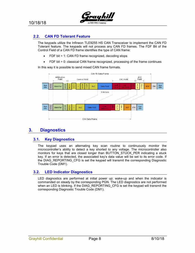
2.2. CAN FD Tolerant Feature The keypads utilize the Infineon TLE9255 HS CAN Transceiver to implement the CAN FD Tolerant feature. The keypads will not process any CAN FD frames. The FDF Bit of the Control Field of a CAN FD frame identifies the type of CAN frame:
• FDF bit = 1: CAN FD frame recognized, decoding stops
• FDF bit = 0: classical CAN frame recognized, processing of the frame continues
In this way it is possible to send mixed CAN frame formats.
3. Diagnostics
3.1. Key Diagnostics The keypad uses an alternating key scan routine to continuously monitor the microcontroller’s ability to detect a key shorted to any voltage. The microcontroller also monitors for keys that are closed longer than BUTTON_STUCK_PER indicating a stuck key. If an error is detected, the associated key’s data value will be set to its error code. If the DIAG_REPORTING_CFG is set the keypad will transmit the corresponding Diagnostic Trouble Code (DM1).
3.2. LED Indicator Diagnostics LED diagnostics are performed at initial power up; wake-up and when the indicator is commanded on steady by the corresponding PGN. The LED diagnostics are not performed when an LED is blinking. If the DIAG_REPORTING_CFG is set the keypad will transmit the corresponding Diagnostic Trouble Code (DM1).
10/18/18
Grayhill Confidential Page 9 8/10/18
4. Keypad Configuration In order to configure the device, the PC tool must send out an Address Claim message using source address 0xFD (Reserved for OEM) with the Grayhill Manufacturer Code of 294 (0x126). When the device detects this address claim, it will allow for configuration of the parameters in Error! Reference source not found. And will be enabled until either a power cycle or another Address Claim message using source address 0xFD with a Manufacturer Code value other than 294 (0x126).
Configuration messages use the Proprietary A PGN and will respond to the message using PDU Specific (PS) values of the device’s source address or the global address of 0xFF. The first byte contains the parameter ID. The message length is variable ranging from 1 to 64 where the upper limit is the longest allowed string value for some parameters.
Unless stated otherwise, new values will not take effect until a device reset occurs.
4.1. Reading Reading parameters is done by only sending the Parameter ID with a message size of one where the actual CAN message’s DLC is one. The parameter payload is returned using the Proprietary A PGN, where the first byte is the parameter ID and the value immediately follows.
4.1.1. Example Reading the Button PGN having the parameter ID of 0x11, with the device having a source address of 0x80, send the following: 0x18EEFFFD 00 00 C0 24 00 00 00 00 -> Tool AC using MFG code of 294
0x18EF80FD 11 -> Prop B PGN with a DLC of 1 and the data bye of 0x11
The unit responds with: 0x1CEFFD80 11 02 FF 00 00 -> Prop B, DLC=3, Param value = 0x0000FF02.
4.2. Writing Sending the parameter ID followed does writing by the payload. The message length is the payload size plus 1 for the parameter ID. Confirmation can be done by immediately performing a read operation of the parameter ID.
4.2.1. Example Setting the Button PGN to the AUXIO1 (0xFED9) with the tool sending to the global address. 0x18EEFFFD 00 00 C0 24 00 00 00 00 -> Tool AC using MFG code of 294
0x18EFF80D 11 D9 FE 00 00 -> Prop B PGN with a DLC of 5
4.3. Parameter List
4.3.1. ECUID Part Number ID=0x00,Size <= 64 ECUID_PN: ASCII string up to 64 characters long occupying field 1 of the ECUID PGN request
10/18/18
Grayhill Confidential Page 10 8/10/18
4.3.2. ECUID Location ID=0x01,Size <= 64 ECUID_LOC: ASCII string up to 64 characters long occupying field 3 of the ECUID PGN request
4.3.3. ECUID Type ID=0x02, Size<= 64 ECUID_TYPE: ASCII string up to 64 characters long occupying field 4 of the ECUID PGN request
4.3.4. ECUID Manufacturer ID=0x03, Size<= 64 ECUID_MFG: ASCII string up to 64 characters long occupying field 4 of the ECUID PGN request
4.3.5. Component ID Make ID=0x04, Size <=5 CI_MAKE: ASCII string up to 5 characters long occupying field 1 of the CI PGN request
4.3.6. Component ID Model ID=0x05, Size<= 64 CI_MODEL: ASCII string up to 64 characters long occupying field 2 of the CI PGN request
4.3.7. Component ID Serial Number ID=0x06, Size<= 64 CI_SN: ASCII string up to 64 characters long occupying field 3 of the CI PGN request
4.3.8. Component ID Unit Number ID=0x07, Size<= 64 CI_UN: ASCII string up to 64 characters long occupying field 4 of the CI PGN request
4.3.9. J1939 Name Identification ID=0x08, Size = 4 NAME_ID: Integer value representing the ID portion of the J1939 Name
4.3.10.J1939 Name Manufacturer Code ID=0x09, Size = 2 NAME_MFG_CODE: Integer value representing the Manufacturer Code portion of the J1939 Name
4.3.11.J1939 Name ECU Instance ID=0x0A, Size = 1 NAME_ECU_INST: Integer value representing the ECU Instance portion of the J1939 Name
4.3.12.J1939 Name Function Instance ID=0x0B, Size = 1 NAME_FUNC_INST: Integer value representing the Function Instance portion of the J1939 Name
4.3.13.J1939 Name Function ID=0x0C, Size = 1 NAME_FUNCTION: Integer value representing the Function portion of the J1939 Name
10/18/18
Grayhill Confidential Page 11 8/10/18
4.3.14.J1939 Name Vehicle System ID=0x0D, Size = 1 NAME_VEH_SYS: Integer value representing the Vehicle System portion of the J1939 Name
4.3.15.J1939 Name Vehicle System Instance ID=0x0E, Size = 1 NAME_VEH_SYS_INST: Integer value representing the Vehicle System Instance portion of the J1939 Name
4.3.16.J1939 Name Industry Group ID=0x0F, Size = 1 NAME_IND_GRP: Integer value representing the Industry Group portion of the J1939 Name
4.3.17.J1939 Name Arbitrary Address Capable ID=0x10, Size = 1 NAME_AAC: Integer value representing the Arbitrary Address Capable portion of the J1939 Name
4.3.18.Button PGN ID=0x11, Size = 4 BUTTON_PGN: The lower 16 bits is the PGN used for transmitting eight data bytes containing button status. The two-bit field occupying locations 17 and 18 determine the data page where 0b00 is Data Page 0. See also: 5.5.25 Prop B (Key Press Data Default PGN) 65282 (0xFF02)
4.3.19.Button Priority ID=0x12, Size = 1 BUTTON_PRI: The lowest three bits set the priority of the PGN. All other bits are ignored.
4.3.20.Button Send On Event ID=0x13, Size = 1 BUTTON_SOE: A non-zero value causes the button PGN to transmit immediately on a button state change.
4.3.21.Button Transmit Period ID=0x14, Size = 1 BUTTON_TX_PER: The value sets the transmission period of the button PGN in units of 10ms. Example: A value of 20 sets the period to 200ms. A value of zero inhibits periodic transmission.
4.3.22.Indicator Status 1 PGN ID=0x15, Size = 4 LED_STAT_1_PGN: The lower 16 bits is the PGN used for transmitting eight data bytes containing the indicator status of indicators 1 through 32. The two-bit field occupying locations 17 and 18 determine the data page where 0b00 is Data Page 0.
4.3.23.Indicator Status 2 PGN ID=0x16, Size = 4 LED_STAT_2_PGN: The lower 16 bits is the PGN used for transmitting eight data bytes containing the indicator status of indicators 33 to 64. The two-bit field occupying locations 17 and 18 determine the data page where 0b00 is Data Page 0.
10/18/18
Grayhill Confidential Page 12 8/10/18
4.3.24.Indicator Status PRI ID=0x17, Size = 1 LED_STAT_PRI: The lowest three bits set the priority of the PGN. All other bits are ignored.
4.3.25.Indicator Status Send On Event ID=0x18, Size = 1 LED_STAT_SOE: A non-zero value causes the indicator PGNs to transmit immediately on an indicator state change.
4.3.26.Indicator Status Transmit Period ID=0x19, Size = 1 LED_STAT_TX_PER: The value sets the transmission period of the indicator PGNs in units of 10ms. Example: A value of 20 sets the period to 200ms. A value of zero inhibits periodic transmission.
4.3.27.Diagnostic Blink Period ID=0x1A, Size = 1 LED_DIAG_BLINK_PER: The value in units of 100ms determines the length of time after power-up that all of the indicators and backlights illuminate at full brightness. Example: A value of 30 will illuminate the lights for 3 seconds. A value of zero inhibits the diagnostic blink at power up.
4.3.28.LED COMM Timeout Period ID=0x1B, Size = 1 LED_TIMEOUT_PER: The value in units of 100ms, determine the length of time that needs to pass with the absence of any CAN traffic responsible for controlling the LEDs. A value of zero disables this feature. The maximum timeout period is 25.5 seconds. The Indicators and Backlights will flash at a 2Hz rate to indicate loss of LED communication when the timer has expired. See also LOW_POWER_DELAY_PER.
4.3.29.LED Stuffing Configuration 1 ID=0x1C, Size = 3 **** GRAYHILL INTERNAL USE ONLY **** DO NOT MODIFY ***
Each bit within the three bytes represents an indicator LED controlled by the first driver and determines if that LED is stuffed or not. This is needed to prevent false failures during LED diagnostics.
4.3.30.LED Stuffing Configuration 2 ID=0x1D, Size = 3 **** GRAYHILL INTERNAL USE ONLY **** DO NOT MODIFY ***
Each bit within the three bytes represents an indicator LED controlled by the second driver and determines if that LED is stuffed or not. This is needed to prevent false failures during LED diagnostics.
4.3.31.Default Indicator Intensity ID=0x1E, Size = 1 LED_IND_DEFAULT: This parameter determines the indicator intensity before the device is commanded to change it. The default value is maximum brightness.
10/18/18
Grayhill Confidential Page 13 8/10/18
4.3.32.Default Backlight Intensity ID=0x1F, Size = 1 LED_BKLT_DEFAULT: This parameter determines the backlight intensity before the device is commanded to change it. The default value is maximum brightness.
4.3.33.Stuck Button Error Timeout Period ID=0x20, Size = 1 BUTTON_STUCK_PER: The value indicates the number of seconds a button needs to register an active press until it throws an error code for the corresponding button.
4.3.34.LED PWM BASE 1 ID=0x21, Size = 24 **** GRAYHILL INTERNAL USE ONLY **** DO NOT MODIFY ***
Each byte corresponds to an indicator LED and is used for balancing the intensity of the indicators when different LED types with different forward voltage drops are used. The valid range is between 0 and 255.
4.3.35.LED IREF BASE 1 ID=0x22, Size = 24 **** GRAYHILL INTERNAL USE ONLY **** DO NOT MODIFY ***
Each byte corresponds to an indicator LED and is used to fine tone the reference current when different LED types with different forward voltage drops are used.
4.3.36.LED PWM BASE 2 ID=0x23, Size = 24 **** GRAYHILL INTERNAL USE ONLY **** DO NOT MODIFY ***
Refer to LED PWM BASE 1, ID=0x21, Size = 24
4.3.37.LED IREF BASE 2 ID=0x24, Size = 24 **** GRAYHILL INTERNAL USE ONLY **** DO NOT MODIFY ***
Refer to LED IREF BASE 1, ID=0x22, Size = 24
4.3.38.DEVICE CONFIG ID=0x25, Size = 2 **** GRAYHILL INTERNAL USE ONLY **** DO NOT MODIFY ***
Byte 1 => Number of Buttons. Valid values (6, 8, 12, and 15)
4.3.39.FLEXIO CONFIG ID=0x26, Size = 1 FLEXIO_CFG: Each nibble within the byte value is used to configure the two Flex IO peripherals. Refer to AUXIO 4 PGN for FlexIO Control.
Flex IO 1 is configured with the lower nibble. Configuration is as follows:
• 0 => Sourcing driver disabled. Input with hardware pulldown only.
• 1 => Sourcing driver enabled (default)
Flex IO 2 is configured with the upper nibble. Configuration is as follows:
• 0 => Sourcing and sinking drivers disabled. Input only. (default)
• 1 => Sourcing enabled, sinking disabled.
10/18/18
Grayhill Confidential Page 14 8/10/18
• 2 => Sourcing disabled, sinking enabled.
• 3 => Push-Pull Enabled.
4.3.40.Demo Mode ID=0x27, Size = 1 DEVICE_DEMO_MODE: A non-zero value, with the exception of FFh, causes the keypad to have the ability to enter demo mode. Demo mode is entered by powering up the keypad while simultaneously holding down BTN#1 and the last button (BTN#6, BTN#8, BTN#12, and BTN#15) of the keypad. All of the indicators will blink twice and demo mode is entered regardless of the LED_DIAG_BLINK_PER setting. 4.3.41. Baud Rate ID=0x28, Size=1 DEVICE_BAUD: The value sets the baud rate of the device according to the following table.
4.3.42.AUXIO1 Priority ID=0x29, Size=1 AUXIO1_PRI: The lowest three bits set the priority of the PGN. All other bits are ignored.
4.3.43.AUXIO1 Send On Event ID=0x2A, Size=1 AUXIO1_SOE: A non-zero value causes the AUXIO PGN to transmit immediately on a FLEXIOx state change when configured as input.
4.3.44.AUXIO1 TX Period ID=0x2B, Size=1 AUXIO1_TX_PER: The value sets the transmission period of the button PGN in units of 10ms. Ex. A value of 20 sets the period to 200ms. A value of zero inhibits periodic transmission.
4.3.45.LOW_POWER_DELAY_PER ID=0x2C, Size=1 LOW_POWER_DELAY_PER: This value, in units of 100ms, determines how long to wait until finally low power mode after all of the conditions to enter low power mode are satisfied. If LED timeout is configured, the sleep timeout period will begin after LED timeout (and FLEXIO2 input low). LOW_POWER_DELAY_PER must be greater than 1 when LOW_POWER_CFG is enabled.
Data Value Baud Rate 0 1000K 1 800K 2 500K
3 (default) 250K 4 125K 5 100K 6 50K 7 20K 8 10K
10/18/18
Grayhill Confidential Page 15 8/10/18
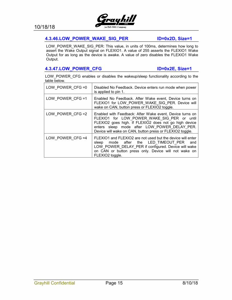
4.3.46.LOW_POWER_WAKE_SIG_PER ID=0x2D, Size=1 LOW_POWER_WAKE_SIG_PER: This value, in units of 100ms, determines how long to assert the Wake Output signal on FLEXIO1. A value of 255 asserts the FLEXIO1 Wake Output for as long as the device is awake. A value of zero disables the FLEXIO1 Wake Output.
4.3.47.LOW_POWER_CFG ID=0x2E, Size=1 LOW_POWER_CFG enables or disables the wakeup/sleep functionality according to the table below.
LOW_POWER_CFG =0 Disabled No Feedback. Device enters run mode when power is applied to pin 1.
LOW_POWER_CFG =1 Enabled No Feedback. After Wake event, Device turns on FLEXIO1 for LOW_POWER_WAKE_SIG_PER. Device will wake on CAN, button press or FLEXIO2 toggle.
LOW_POWER_CFG =2 Enabled with Feedback: After Wake event, Device turns on FLEXIO1 for LOW_POWER_WAKE_SIG_PER or until FLEXIO2 goes high. If FLEXIO2 does not go high device enters sleep mode after LOW_POWER_DELAY_PER. Device will wake on CAN, button press or FLEXIO2 toggle.
LOW_POWER_CFG =4 FLEXIO1 and FLEXIO2 are not used but the device will enter sleep mode after the LED_TIMEOUT_PER and LOW_POWER_DELAY_PER if configured. Device will wake on CAN or button press only. Device will not wake on FLEXIO2 toggle.
10/18/18
Grayhill Confidential Page 16 8/10/18
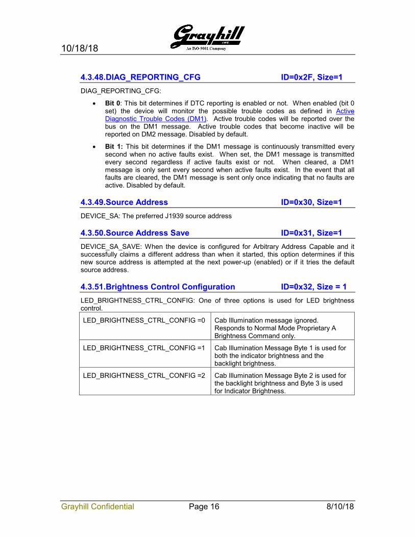
4.3.48.DIAG_REPORTING_CFG ID=0x2F, Size=1 DIAG_REPORTING_CFG:
• Bit 0: This bit determines if DTC reporting is enabled or not. When enabled (bit 0 set) the device will monitor the possible trouble codes as defined in Active Diagnostic Trouble Codes (DM1). Active trouble codes will be reported over the bus on the DM1 message. Active trouble codes that become inactive will be reported on DM2 message. Disabled by default.
• Bit 1: This bit determines if the DM1 message is continuously transmitted every second when no active faults exist. When set, the DM1 message is transmitted every second regardless if active faults exist or not. When cleared, a DM1 message is only sent every second when active faults exist. In the event that all faults are cleared, the DM1 message is sent only once indicating that no faults are active. Disabled by default.
4.3.49.Source Address ID=0x30, Size=1 DEVICE_SA: The preferred J1939 source address
4.3.50.Source Address Save ID=0x31, Size=1 DEVICE_SA_SAVE: When the device is configured for Arbitrary Address Capable and it successfully claims a different address than when it started, this option determines if this new source address is attempted at the next power-up (enabled) or if it tries the default source address.
4.3.51.Brightness Control Configuration ID=0x32, Size = 1 LED_BRIGHTNESS_CTRL_CONFIG: One of three options is used for LED brightness control.
LED_BRIGHTNESS_CTRL_CONFIG =0 Cab Illumination message ignored. Responds to Normal Mode Proprietary A Brightness Command only.
LED_BRIGHTNESS_CTRL_CONFIG =1 Cab Illumination Message Byte 1 is used for both the indicator brightness and the backlight brightness.
LED_BRIGHTNESS_CTRL_CONFIG =2 Cab Illumination Message Byte 2 is used for the backlight brightness and Byte 3 is used for Indicator Brightness.
10/18/18
Grayhill Confidential Page 17 8/10/18
5. Communications
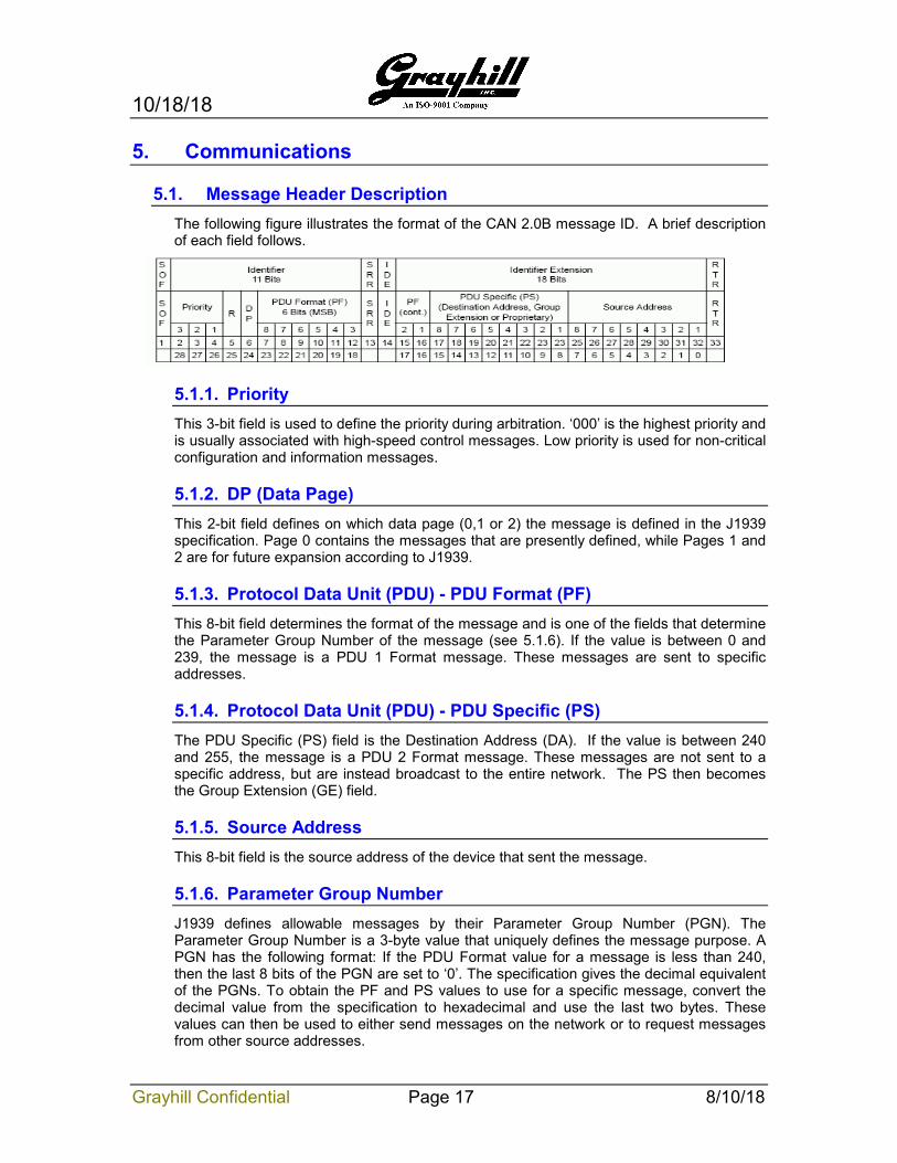
5.1. Message Header Description The following figure illustrates the format of the CAN 2.0B message ID. A brief description of each field follows.
5.1.1. Priority This 3-bit field is used to define the priority during arbitration. ‘000’ is the highest priority and is usually associated with high-speed control messages. Low priority is used for non-critical configuration and information messages.
5.1.2. DP (Data Page) This 2-bit field defines on which data page (0,1 or 2) the message is defined in the J1939 specification. Page 0 contains the messages that are presently defined, while Pages 1 and 2 are for future expansion according to J1939.
5.1.3. Protocol Data Unit (PDU) - PDU Format (PF) This 8-bit field determines the format of the message and is one of the fields that determine the Parameter Group Number of the message (see 5.1.6). If the value is between 0 and 239, the message is a PDU 1 Format message. These messages are sent to specific addresses.
5.1.4. Protocol Data Unit (PDU) - PDU Specific (PS) The PDU Specific (PS) field is the Destination Address (DA). If the value is between 240 and 255, the message is a PDU 2 Format message. These messages are not sent to a specific address, but are instead broadcast to the entire network. The PS then becomes the Group Extension (GE) field.
5.1.5. Source Address This 8-bit field is the source address of the device that sent the message.
5.1.6. Parameter Group Number J1939 defines allowable messages by their Parameter Group Number (PGN). The Parameter Group Number is a 3-byte value that uniquely defines the message purpose. A PGN has the following format: If the PDU Format value for a message is less than 240, then the last 8 bits of the PGN are set to ‘0’. The specification gives the decimal equivalent of the PGNs. To obtain the PF and PS values to use for a specific message, convert the decimal value from the specification to hexadecimal and use the last two bytes. These values can then be used to either send messages on the network or to request messages from other source addresses.
10/18/18
Grayhill Confidential Page 18 8/10/18
5.2. Bit-field Location and Byte Ordering The byte and bit ordering and location within the data field are per the J1939 specification. The first data byte is sent first and is referenced as Byte 1. The LSB of the data bytes are on the right and are referenced as Bit 1.
The convention used to locate a parameter in the data field is the same as specified in SAE-J1939/71. The format used is “Rx” where R is the byte number and x is the starting bit number within the byte. The length is the number of bits starting at this point.
Example 1: Location 4.3 with a length of 3 bits would have the value of 1 as illustrated below.
Byte 4 = 0x67 = 0b01100111. The bold value is the three-bit field holding a value of 0b001.
Example 2: Location 4.3 with a length of 3 bits would have the value of 6 as illustrated below.
Byte 4 = 0x7b = 0b01111011. The bold value is the three-bit field holding a value of 0b110.
5.3. Keypad Source Address The source address of the Grayhill standard keypad is set to 128 (80h) at the factory. This may be modified either dynamically if Dynamic Addressing is turned on, with the Commanded Address message in accordance with J1939-81, or with the Configuration Command (requires a reset). The source address value is stored in non-volatile memory. The ability to change the source address will allow multiple keypads to coexist in the same system.
5.4. Physical Layer The default bit rate is 250kbps per J1939/11. J1939/14 defines 500k. ISO11898-2 defines CAN-FD.
The connector is a 6 pin Deutsch equivalent with the following pin out: 1. Power 2. Ground 3. FIO1 4. FIO2 5. CAN_H 6. CAN_L
10/18/18
Grayhill Confidential Page 19 8/10/18
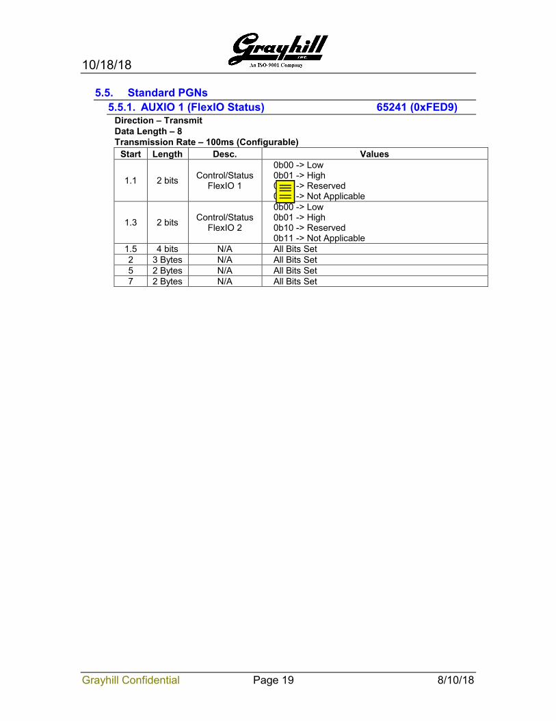
5.5. Standard PGNs 5.5.1. AUXIO 1 (FlexIO Status) 65241 (0xFED9)
Direction – Transmit Data Length – 8 Transmission Rate – 100ms (Configurable)
Start Length Desc. Values
1.1 2 bits Control/Status FlexIO 1
0b00 -> Low 0b01 -> High 0b10 -> Reserved 0b11 -> Not Applicable
1.3 2 bits Control/Status FlexIO 2
0b00 -> Low 0b01 -> High 0b10 -> Reserved 0b11 -> Not Applicable
1.5 4 bits N/A All Bits Set 2 3 Bytes N/A All Bits Set 5 2 Bytes N/A All Bits Set 7 2 Bytes N/A All Bits Set
10/18/18
Grayhill Confidential Page 20 8/10/18
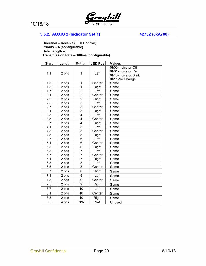
5.5.2. AUXIO 2 (Indicator Set 1) 42752 (0xA700)
Direction – Receive (LED Control) Priority – 6 (configurable) Data Length – 8 Transmission Rate – 100ms (configurable)
Start Length Button LED Pos Values
1.1 2 bits 1 Left
0b00-Indicator Off 0b01-Indicator On 0b10-Indicator Blink 0b11-No Change
1.3 2 bits 1 Center Same 1.5 2 bits 1 Right Same 1.7 2 bits 2 Left Same 2.1 2 bits 2 Center Same 2.3 2 bits 2 Right Same 2.5 2 bits 3 Left Same 2.7 2 bits 3 Center Same 3.1 2 bits 3 Right Same 3.3 2 bits 4 Left Same 3.5 2 bits 4 Center Same 3.7 2 bits 4 Right Same 4.1 2 bits 5 Left Same 4.3 2 bits 5 Center Same 4.5 2 bits 5 Right Same 4.7 2 bits 6 Left Same 5.1 2 bits 6 Center Same 5.3 2 bits 6 Right Same 5.5 2 bits 7 Left Same 5.7 2 bits 7 Center Same 6.1 2 bits 7 Right Same 6.3 2 bits 8 Left Same 6.5 2 bits 8 Center Same 6.7 2 bits 8 Right Same 7.1 2 bits 9 Left Same 7.3 2 bits 9 Center Same 7.5 2 bits 9 Right Same 7.7 2 bits 10 Left Same 8.1 2 bits 10 Center Same 8.3 2 bits 10 Right Same 8.5 4 bits N/A N/A Unused
10/18/18
Grayhill Confidential Page 21 8/10/18
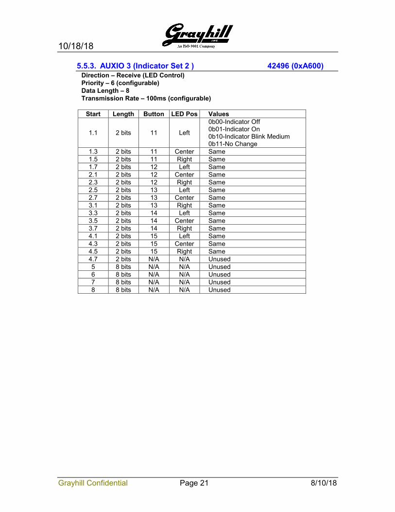
5.5.3. AUXIO 3 (Indicator Set 2 ) 42496 (0xA600) Direction – Receive (LED Control) Priority – 6 (configurable) Data Length – 8 Transmission Rate – 100ms (configurable)
Start Length Button LED Pos Values
1.1 2 bits 11 Left
0b00-Indicator Off 0b01-Indicator On 0b10-Indicator Blink Medium 0b11-No Change
1.3 2 bits 11 Center Same 1.5 2 bits 11 Right Same 1.7 2 bits 12 Left Same 2.1 2 bits 12 Center Same 2.3 2 bits 12 Right Same 2.5 2 bits 13 Left Same 2.7 2 bits 13 Center Same 3.1 2 bits 13 Right Same 3.3 2 bits 14 Left Same 3.5 2 bits 14 Center Same 3.7 2 bits 14 Right Same 4.1 2 bits 15 Left Same 4.3 2 bits 15 Center Same 4.5 2 bits 15 Right Same 4.7 2 bits N/A N/A Unused 5 8 bits N/A N/A Unused 6 8 bits N/A N/A Unused 7 8 bits N/A N/A Unused 8 8 bits N/A N/A Unused
10/18/18
Grayhill Confidential Page 22 8/10/18
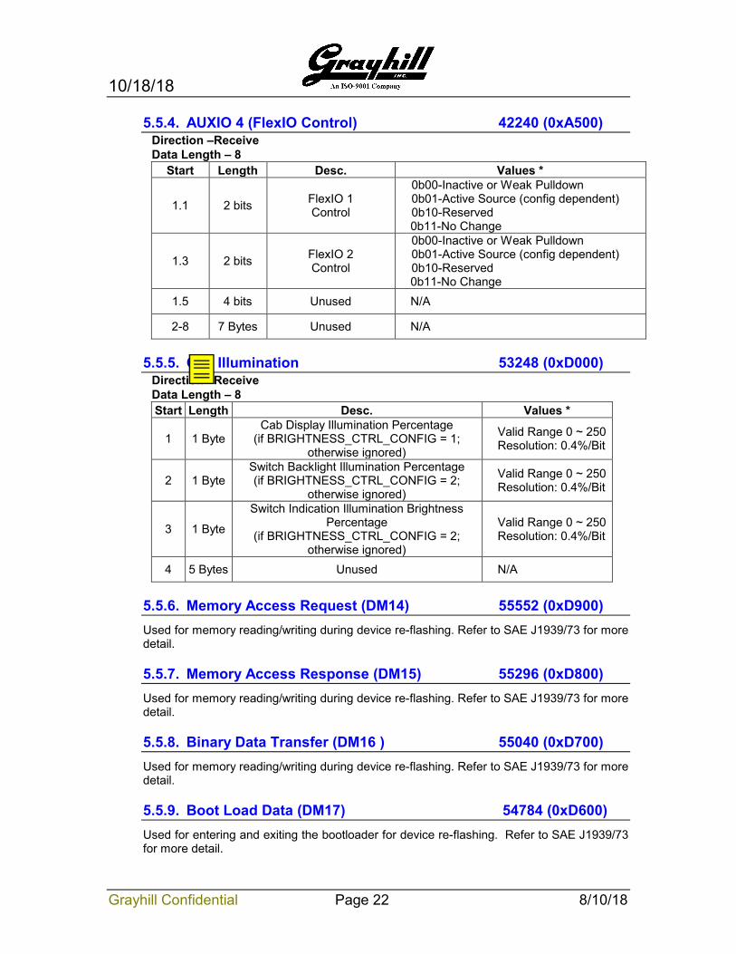
5.5.4. AUXIO 4 (FlexIO Control) 42240 (0xA500) Direction –Receive Data Length – 8
Start Length Desc. Values *
1.1 2 bits FlexIO 1 Control
0b00-Inactive or Weak Pulldown 0b01-Active Source (config dependent) 0b10-Reserved 0b11-No Change
1.3 2 bits FlexIO 2 Control
0b00-Inactive or Weak Pulldown 0b01-Active Source (config dependent) 0b10-Reserved 0b11-No Change
1.5 4 bits Unused N/A
2-8 7 Bytes Unused N/A
5.5.5. Cab Illumination 53248 (0xD000) Direction –Receive Data Length – 8 Start Length Desc. Values *
1 1 Byte Cab Display Illumination Percentage
(if BRIGHTNESS_CTRL_CONFIG = 1; otherwise ignored)
Valid Range 0 ~ 250 Resolution: 0.4%/Bit
2 1 Byte Switch Backlight Illumination Percentage (if BRIGHTNESS_CTRL_CONFIG = 2;
otherwise ignored)
Valid Range 0 ~ 250 Resolution: 0.4%/Bit
3 1 Byte
Switch Indication Illumination Brightness Percentage
(if BRIGHTNESS_CTRL_CONFIG = 2; otherwise ignored)
Valid Range 0 ~ 250 Resolution: 0.4%/Bit
4 5 Bytes Unused N/A
5.5.6. Memory Access Request (DM14) 55552 (0xD900) Used for memory reading/writing during device re-flashing. Refer to SAE J1939/73 for more detail.
5.5.7. Memory Access Response (DM15) 55296 (0xD800) Used for memory reading/writing during device re-flashing. Refer to SAE J1939/73 for more detail.
5.5.8. Binary Data Transfer (DM16 ) 55040 (0xD700) Used for memory reading/writing during device re-flashing. Refer to SAE J1939/73 for more detail.
5.5.9. Boot Load Data (DM17) 54784 (0xD600) Used for entering and exiting the bootloader for device re-flashing. Refer to SAE J1939/73 for more detail.
10/18/18
Grayhill Confidential Page 23 8/10/18
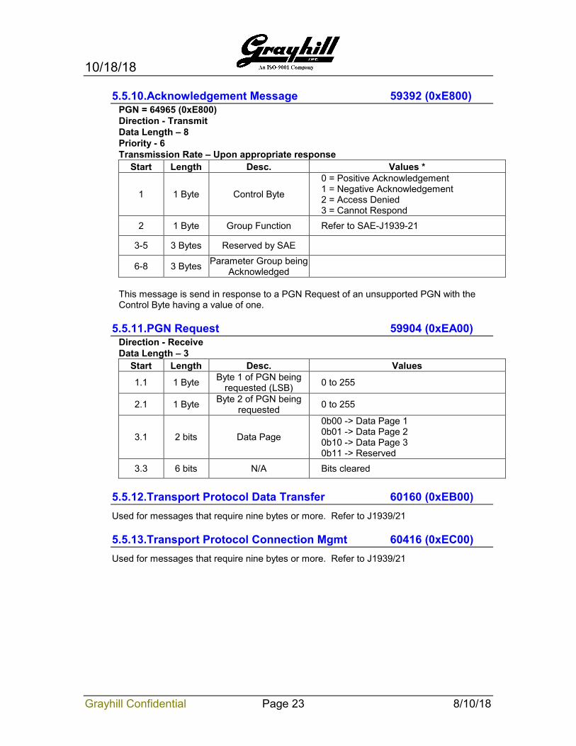
5.5.10.Acknowledgement Message 59392 (0xE800) PGN = 64965 (0xE800) Direction - Transmit Data Length – 8 Priority - 6 Transmission Rate – Upon appropriate response
Start Length Desc. Values *
1 1 Byte Control Byte
0 = Positive Acknowledgement 1 = Negative Acknowledgement 2 = Access Denied 3 = Cannot Respond
2 1 Byte Group Function Refer to SAE-J1939-21
3-5 3 Bytes Reserved by SAE
6-8 3 Bytes Parameter Group being Acknowledged
This message is send in response to a PGN Request of an unsupported PGN with the Control Byte having a value of one.
5.5.11.PGN Request 59904 (0xEA00) Direction - Receive Data Length – 3
Start Length Desc. Values
1.1 1 Byte Byte 1 of PGN being requested (LSB) 0 to 255
2.1 1 Byte Byte 2 of PGN being requested 0 to 255
3.1 2 bits Data Page
0b00 -> Data Page 1 0b01 -> Data Page 2 0b10 -> Data Page 3 0b11 -> Reserved
3.3 6 bits N/A Bits cleared
5.5.12.Transport Protocol Data Transfer 60160 (0xEB00) Used for messages that require nine bytes or more. Refer to J1939/21
5.5.13.Transport Protocol Connection Mgmt 60416 (0xEC00) Used for messages that require nine bytes or more. Refer to J1939/21
10/18/18
Grayhill Confidential Page 24 8/10/18
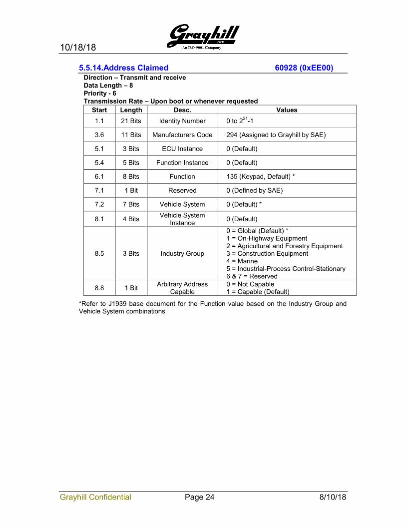
5.5.14.Address Claimed 60928 (0xEE00) Direction – Transmit and receive Data Length – 8 Priority - 6 Transmission Rate – Upon boot or whenever requested
Start Length Desc. Values 1.1 21 Bits Identity Number 0 to 221-1
3.6 11 Bits Manufacturers Code 294 (Assigned to Grayhill by SAE)
5.1 3 Bits ECU Instance 0 (Default)
5.4 5 Bits Function Instance 0 (Default)
6.1 8 Bits Function 135 (Keypad, Default) *
7.1 1 Bit Reserved 0 (Defined by SAE)
7.2 7 Bits Vehicle System 0 (Default) *
8.1 4 Bits Vehicle System Instance 0 (Default)
8.5 3 Bits Industry Group
0 = Global (Default) * 1 = On-Highway Equipment 2 = Agricultural and Forestry Equipment 3 = Construction Equipment 4 = Marine 5 = Industrial-Process Control-Stationary 6 & 7 = Reserved
8.8 1 Bit Arbitrary Address Capable
0 = Not Capable 1 = Capable (Default)
*Refer to J1939 base document for the Function value based on the Industry Group and Vehicle System combinations
10/18/18
Grayhill Confidential Page 25 8/10/18
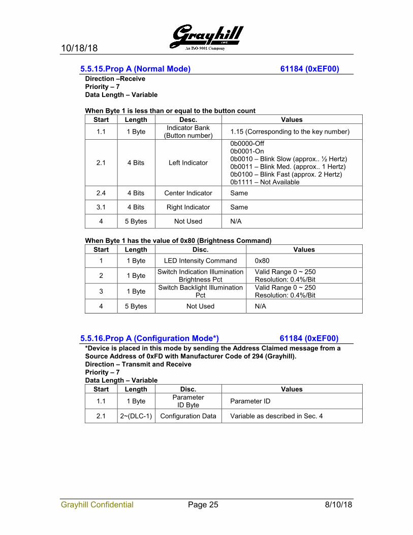
5.5.15.Prop A (Normal Mode) 61184 (0xEF00) Direction –Receive Priority – 7 Data Length – Variable When Byte 1 is less than or equal to the button count
Start Length Desc. Values
1.1 1 Byte Indicator Bank (Button number) 1.15 (Corresponding to the key number)
2.1 4 Bits Left Indicator
0b0000-Off 0b0001-On 0b0010 – Blink Slow (approx.. ½ Hertz) 0b0011 – Blink Med. (approx.. 1 Hertz) 0b0100 – Blink Fast (approx. 2 Hertz) 0b1111 – Not Available
2.4 4 Bits Center Indicator Same
3.1 4 Bits Right Indicator Same
4 5 Bytes Not Used N/A
When Byte 1 has the value of 0x80 (Brightness Command)
Start Length Disc. Values 1 1 Byte LED Intensity Command 0x80
2 1 Byte Switch Indication Illumination Brightness Pct
Valid Range 0 ~ 250 Resolution: 0.4%/Bit
3 1 Byte Switch Backlight Illumination Pct
Valid Range 0 ~ 250 Resolution: 0.4%/Bit
4 5 Bytes Not Used N/A
5.5.16.Prop A (Configuration Mode*) 61184 (0xEF00) *Device is placed in this mode by sending the Address Claimed message from a Source Address of 0xFD with Manufacturer Code of 294 (Grayhill). Direction – Transmit and Receive Priority – 7 Data Length – Variable
Start Length Disc. Values
1.1 1 Byte Parameter ID Byte Parameter ID
2.1 2~(DLC-1) Configuration Data Variable as described in Sec. 4
10/18/18
Grayhill Confidential Page 26 8/10/18
5.5.17.ECU Identification Information 64965 (0xFDC5) Direction - Transmit Data Length – Variable Transmission Rate – Upon Request Multi Packet Transferred – Yes
Start Length Disc. Values * A <=64 ECU Part Number Ex. “3KYY1001-1”
B <=64 ECU Serial Number Ex. “123456”
C <=64 ECU Location Ex. “CAB”
D <=64 ECU Type “KEYPAD”
5.5.18.Active Diagnostic Trouble Codes (DM1) 65226 (0xFECA) The Diagnostic Trouble Code PGN uses the format described in J1939-73 that broadcasts to no specific address the diagnostic status of the keys, LEDs, IO etc. See APPENDIX A Diagnostic Trouble Codes
PGN: 65226 (0xFECA) Direction: Transmit Data Page: 0 PDU Format: 254 PDU Specific: 202 Priority: 6 Data Length: Variable (see transport protocol defined in SAE J1939-21) TX Rate: 1s or On Change or On Request
5.5.19.Previously Active Trouble Codes (DM2) 65226 (0xFECB) Faults that go active then inactive can be read doing a PGN request for the DM2 message.
PGN: 65226 (0xFECB) Direction: Transmit Data Page: 0 PDU Format: 254 PDU Specific: 202 Priority: 6 Data Length: Variable (see transport protocol defined in SAE J1939-21) TX Rate: On Request
10/18/18
Grayhill Confidential Page 27 8/10/18
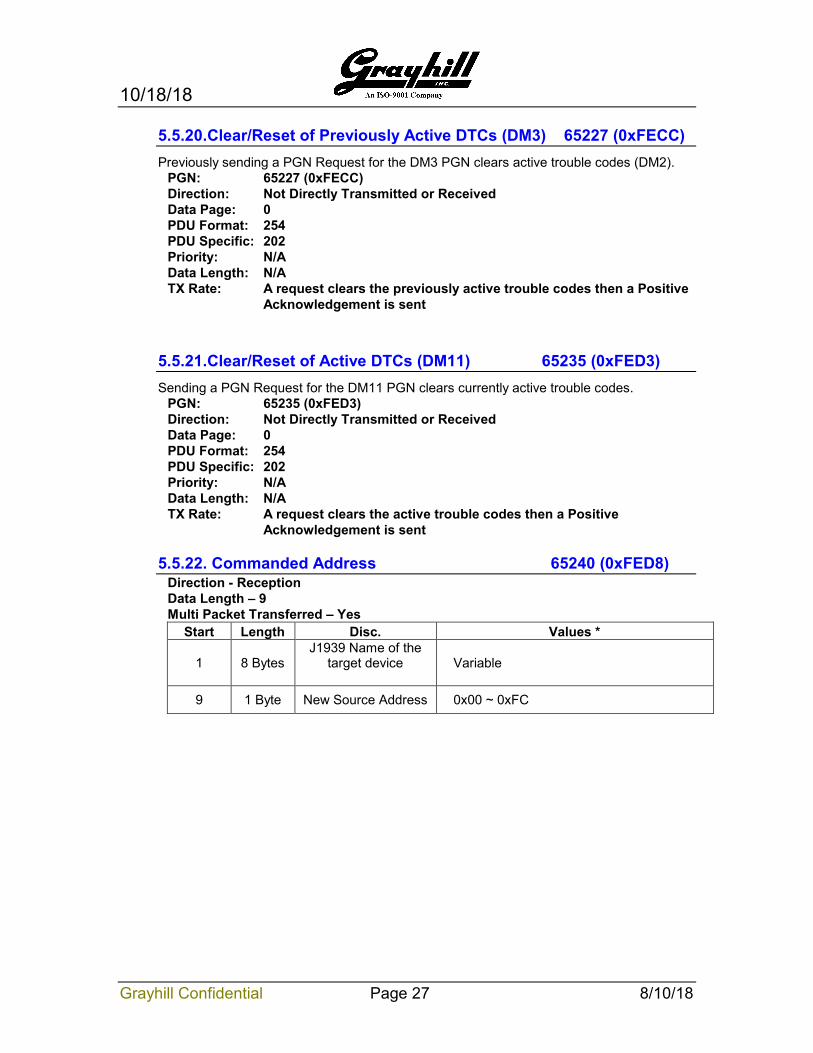
5.5.20.Clear/Reset of Previously Active DTCs (DM3) 65227 (0xFECC) Previously sending a PGN Request for the DM3 PGN clears active trouble codes (DM2).
PGN: 65227 (0xFECC) Direction: Not Directly Transmitted or Received Data Page: 0 PDU Format: 254 PDU Specific: 202 Priority: N/A Data Length: N/A TX Rate: A request clears the previously active trouble codes then a Positive
Acknowledgement is sent
5.5.21.Clear/Reset of Active DTCs (DM11) 65235 (0xFED3) Sending a PGN Request for the DM11 PGN clears currently active trouble codes.
PGN: 65235 (0xFED3) Direction: Not Directly Transmitted or Received Data Page: 0 PDU Format: 254 PDU Specific: 202 Priority: N/A Data Length: N/A TX Rate: A request clears the active trouble codes then a Positive
Acknowledgement is sent
5.5.22. Commanded Address 65240 (0xFED8) Direction - Reception Data Length – 9 Multi Packet Transferred – Yes
Start Length Disc. Values *
1 8 Bytes J1939 Name of the
target device
Variable
9 1 Byte New Source Address 0x00 ~ 0xFC
10/18/18
Grayhill Confidential Page 28 8/10/18
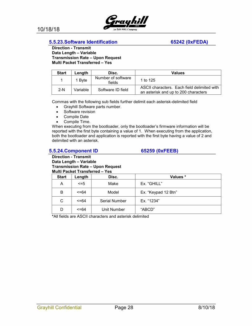
5.5.23.Software Identification 65242 (0xFEDA) Direction - Transmit Data Length – Variable Transmission Rate – Upon Request Multi Packet Transferred – Yes
Start Length Disc. Values
1 1 Byte Number of software fields 1 to 125
2-N Variable Software ID field ASCII characters. Each field delimited with an asterisk and up to 200 characters
Commas with the following sub fields further delimit each asterisk-delimited field • Grayhill Software parts number. • Software revision • Compile Date • Compile Time.
When executing from the bootloader, only the bootloader’s firmware information will be reported with the first byte containing a value of 1. When executing from the application, both the bootloader and application is reported with the first byte having a value of 2 and delimited with an asterisk.
5.5.24.Component ID 65259 (0xFEEB) Direction - Transmit Data Length – Variable Transmission Rate – Upon Request Multi Packet Transferred – Yes
Start Length Disc. Values * A <=5 Make Ex. “GHILL”
B <=64 Model Ex. “Keypad 12 Btn”
C <=64 Serial Number Ex. “1234”
D <=64 Unit Number “ABCD”
*All fields are ASCII characters and asterisk delimited
10/18/18
Grayhill Confidential Page 29 8/10/18
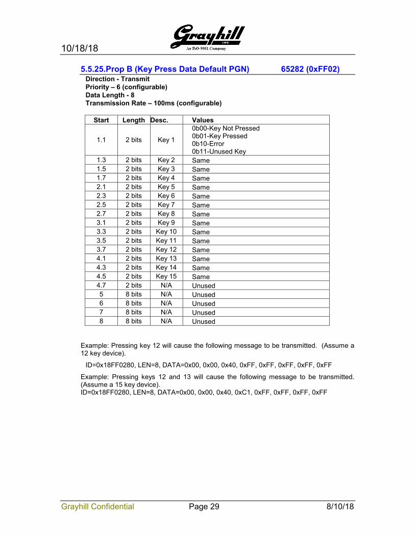
5.5.25.Prop B (Key Press Data Default PGN) 65282 (0xFF02) Direction - Transmit Priority – 6 (configurable) Data Length - 8 Transmission Rate – 100ms (configurable)
Start Length Desc. Values
1.1 2 bits Key 1
0b00-Key Not Pressed 0b01-Key Pressed 0b10-Error 0b11-Unused Key
1.3 2 bits Key 2 Same 1.5 2 bits Key 3 Same 1.7 2 bits Key 4 Same 2.1 2 bits Key 5 Same 2.3 2 bits Key 6 Same 2.5 2 bits Key 7 Same 2.7 2 bits Key 8 Same 3.1 2 bits Key 9 Same 3.3 2 bits Key 10 Same 3.5 2 bits Key 11 Same 3.7 2 bits Key 12 Same 4.1 2 bits Key 13 Same 4.3 2 bits Key 14 Same 4.5 2 bits Key 15 Same 4.7 2 bits N/A Unused 5 8 bits N/A Unused 6 8 bits N/A Unused 7 8 bits N/A Unused 8 8 bits N/A Unused
Example: Pressing key 12 will cause the following message to be transmitted. (Assume a 12 key device).
ID=0x18FF0280, LEN=8, DATA=0x00, 0x00, 0x40, 0xFF, 0xFF, 0xFF, 0xFF, 0xFF
Example: Pressing keys 12 and 13 will cause the following message to be transmitted. (Assume a 15 key device). ID=0x18FF0280, LEN=8, DATA=0x00, 0x00, 0x40, 0xC1, 0xFF, 0xFF, 0xFF, 0xFF
10/18/18
Grayhill Confidential Page 30 8/10/18
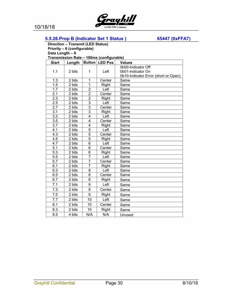
5.5.26.Prop B (Indicator Set 1 Status ) 65447 (0xFFA7) Direction – Transmit (LED Status) Priority – 6 (configurable) Data Length – 8 Transmission Rate – 100ms (configurable)
Start Length Button LED Pos Values
1.1 2 bits 1 Left 0b00-Indicator Off 0b01-Indicator On 0b10-Indicator Error (short or Open)
1.3 2 bits 1 Center Same 1.5 2 bits 1 Right Same 1.7 2 bits 2 Left Same 2.1 2 bits 2 Center Same 2.3 2 bits 2 Right Same 2.5 2 bits 3 Left Same 2.7 2 bits 3 Center Same 3.1 2 bits 3 Right Same 3.3 2 bits 4 Left Same 3.5 2 bits 4 Center Same 3.7 2 bits 4 Right Same 4.1 2 bits 5 Left Same 4.3 2 bits 5 Center Same 4.5 2 bits 5 Right Same 4.7 2 bits 6 Left Same 5.1 2 bits 6 Center Same 5.3 2 bits 6 Right Same 5.5 2 bits 7 Left Same 5.7 2 bits 7 Center Same 6.1 2 bits 7 Right Same 6.3 2 bits 8 Left Same 6.5 2 bits 8 Center Same 6.7 2 bits 8 Right Same 7.1 2 bits 9 Left Same 7.3 2 bits 9 Center Same 7.5 2 bits 9 Right Same 7.7 2 bits 10 Left Same 8.1 2 bits 10 Center Same 8.3 2 bits 10 Right Same 8.5 4 bits N/A N/A Unused
10/18/18
Grayhill Confidential Page 31 8/10/18
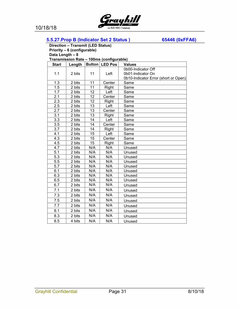
5.5.27.Prop B (Indicator Set 2 Status ) 65446 (0xFFA6) Direction – Transmit (LED Status) Priority – 6 (configurable) Data Length – 8 Transmission Rate – 100ms (configurable)
Start Length Button LED Pos Values
1.1 2 bits 11 Left 0b00-Indicator Off 0b01-Indicator On 0b10-Indicator Error (short or Open)
1.3 2 bits 11 Center Same 1.5 2 bits 11 Right Same 1.7 2 bits 12 Left Same 2.1 2 bits 12 Center Same 2.3 2 bits 12 Right Same 2.5 2 bits 13 Left Same 2.7 2 bits 13 Center Same 3.1 2 bits 13 Right Same 3.3 2 bits 14 Left Same 3.5 2 bits 14 Center Same 3.7 2 bits 14 Right Same 4.1 2 bits 15 Left Same 4.3 2 bits 15 Center Same 4.5 2 bits 15 Right Same 4.7 2 bits N/A N/A Unused 5.1 2 bits N/A N/A Unused 5.3 2 bits N/A N/A Unused 5.5 2 bits N/A N/A Unused 5.7 2 bits N/A N/A Unused 6.1 2 bits N/A N/A Unused 6.3 2 bits N/A N/A Unused 6.5 2 bits N/A N/A Unused 6.7 2 bits N/A N/A Unused 7.1 2 bits N/A N/A Unused 7.3 2 bits N/A N/A Unused 7.5 2 bits N/A N/A Unused 7.7 2 bits N/A N/A Unused 8.1 2 bits N/A N/A Unused 8.3 2 bits N/A N/A Unused 8.5 4 bits N/A N/A Unused
10/18/18
Grayhill Confidential Page 32 8/10/18
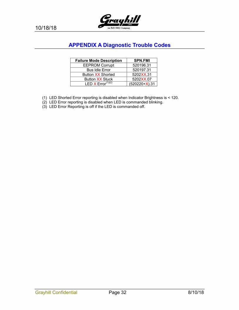
APPENDIX A Diagnostic Trouble Codes
Failure Mode Description SPN.FMI EEPROM Corrupt 520196.31
Bus Idle Error 520197.31 Button XX Shorted 5202XX.31 Button XX Stuck 5202XX.07 LED X Error(1)(2) (520220+X).31
(1) LED Shorted Error reporting is disabled when Indicator Brightness is < 120. (2) LED Error reporting is disabled when LED is commanded blinking. (3) LED Error Reporting is off if the LED is commanded off.
10/18/18
Grayhill Confidential Page 33 8/10/18
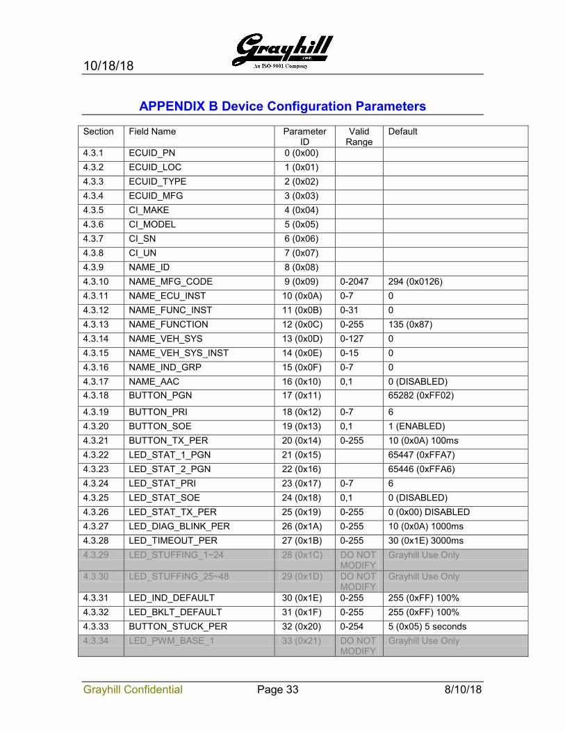
APPENDIX B Device Configuration Parameters Section Field Name Parameter
ID Valid
Range Default
4.3.1 ECUID_PN 0 (0x00) 4.3.2 ECUID_LOC 1 (0x01) 4.3.3 ECUID_TYPE 2 (0x02) 4.3.4 ECUID_MFG 3 (0x03) 4.3.5 CI_MAKE 4 (0x04) 4.3.6 CI_MODEL 5 (0x05) 4.3.7 CI_SN 6 (0x06) 4.3.8 CI_UN 7 (0x07) 4.3.9 NAME_ID 8 (0x08) 4.3.10 NAME_MFG_CODE 9 (0x09) 0-2047 294 (0x0126) 4.3.11 NAME_ECU_INST 10 (0x0A) 0-7 0 4.3.12 NAME_FUNC_INST 11 (0x0B) 0-31 0 4.3.13 NAME_FUNCTION 12 (0x0C) 0-255 135 (0x87) 4.3.14 NAME_VEH_SYS 13 (0x0D) 0-127 0 4.3.15 NAME_VEH_SYS_INST 14 (0x0E) 0-15 0 4.3.16 NAME_IND_GRP 15 (0x0F) 0-7 0 4.3.17 NAME_AAC 16 (0x10) 0,1 0 (DISABLED) 4.3.18 BUTTON_PGN 17 (0x11) 65282 (0xFF02)
4.3.19 BUTTON_PRI 18 (0x12) 0-7 6 4.3.20 BUTTON_SOE 19 (0x13) 0,1 1 (ENABLED) 4.3.21 BUTTON_TX_PER 20 (0x14) 0-255 10 (0x0A) 100ms 4.3.22 LED_STAT_1_PGN 21 (0x15) 65447 (0xFFA7) 4.3.23 LED_STAT_2_PGN 22 (0x16) 65446 (0xFFA6) 4.3.24 LED_STAT_PRI 23 (0x17) 0-7 6 4.3.25 LED_STAT_SOE 24 (0x18) 0,1 0 (DISABLED) 4.3.26 LED_STAT_TX_PER 25 (0x19) 0-255 0 (0x00) DISABLED 4.3.27 LED_DIAG_BLINK_PER 26 (0x1A) 0-255 10 (0x0A) 1000ms 4.3.28 LED_TIMEOUT_PER 27 (0x1B) 0-255 30 (0x1E) 3000ms 4.3.29 LED_STUFFING_1~24 28 (0x1C) DO NOT
MODIFY Grayhill Use Only
4.3.30 LED_STUFFING_25~48 29 (0x1D) DO NOT MODIFY
Grayhill Use Only
4.3.31 LED_IND_DEFAULT 30 (0x1E) 0-255 255 (0xFF) 100% 4.3.32 LED_BKLT_DEFAULT 31 (0x1F) 0-255 255 (0xFF) 100% 4.3.33 BUTTON_STUCK_PER 32 (0x20) 0-254 5 (0x05) 5 seconds 4.3.34 LED_PWM_BASE_1 33 (0x21) DO NOT
MODIFY Grayhill Use Only
10/18/18
Grayhill Confidential Page 34 8/10/18
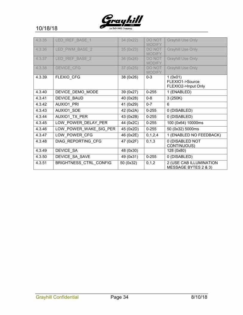
4.3.35 LED_IREF_BASE_1 34 (0x22) DO NOT MODIFY
Grayhill Use Only
4.3.36 LED_PWM_BASE_2 35 (0x23) DO NOT MODIFY
Grayhill Use Only
4.3.37 LED_IREF_BASE_2 36 (0x24) DO NOT MODIFY
Grayhill Use Only
4.3.38 DEVICE_CFG 37 (0x25) DO NOT MODIFY
Grayhill Use Only
4.3.39 FLEXIO_CFG 38 (0x26) 0-3 1 (0x01) FLEXIO1->Source FLEXIO2->Input Only
4.3.40 DEVICE_DEMO_MODE 39 (0x27) 0-255 1 (ENABLED) 4.3.41 DEVICE_BAUD 40 (0x28) 0-8 3 (250K) 4.3.42 AUXIO1_PRI 41 (0x29) 0-7 6 4.3.43 AUXIO1_SOE 42 (0x2A) 0-255 0 (DISABLED) 4.3.44 AUXIO1_TX_PER 43 (0x2B) 0-255 0 (DISABLED) 4.3.45 LOW_POWER_DELAY_PER 44 (0x2C) 0-255 100 (0x64) 10000ms 4.3.46 LOW_POWER_WAKE_SIG_PER 45 (0x2D) 0-255 50 (0x32) 5000ms 4.3.47 LOW_POWER_CFG 46 (0x2E) 0,1,2,4 1 (ENABLED NO FEEDBACK) 4.3.48 DIAG_REPORTING_CFG 47 (0x2F) 0,1,3 0 (DISABLED NOT
CONTINUOUS) 4.3.49 DEVICE_SA 48 (0x30) 128 (0x80) 4.3.50 DEVICE_SA_SAVE 49 (0x31) 0-255 0 (DISABLED) 4.3.51 BRIGHTNESS_CTRL_CONFIG 50 (0x32) 0,1,2 2 (USE CAB ILLUMINATION
MESSAGE BYTES 2 & 3)


![DCU 305 R3 CAN / J1939 Manual - Auto-Maskin§ [a] SAE, J1939-71 § [b] SAE, J1939-73 § [c] Conrad Etschberger, “Controller Area Network” ... CAN / J1939 Manual CAN / J1939 –](https://img.pdfslide.us/doc/110x75/5ae535d97f8b9a7b218f6863/dcu-305-r3-can-j1939-manual-auto-maskin-a-sae-j1939-71-b-sae-j1939-73.jpg)