Embed Size (px)
Citation preview
Technical Article
Networking Heavy-Duty Vehicles Based on SAE J1939 1/12
Networking Heavy-Duty Vehicles Based on SAE J1939
From Parameter Group to plug-and-play Application
In networking ECUs in heavy-duty vehicles, it is the J1939 protocol that
plays a key role. J1939 networks are based on the CAN bus (high-speed
CAN per ISO11898); they are primarily used in powertrain and chassis
components. The protocol creates a uniform basis for communication
between electronic control units, and it supports the plug-and-play
principle. Special J1939 tools and software components spare developers
from needing to train in the details of the J1939 protocol, and they
improve the quality of the development process.
The J1939 protocol – founded in the USA and defined by the Society of
Automotive Engineers (SAE) – serves above all to preserve a uniform
perspective and uniform handling of the most common vehicle components of
various vehicle types and manufacturers. In this context, it is interesting to note
certain distinct differences between the European and North-American heavy-
duty vehicle markets. For example, heavy-duty vehicle buyers in the USA have
prescribed to OEMs which components they need to install in specific vehicles.
Technical Article
Networking Heavy-Duty Vehicles Based on SAE J1939 2/12
In Europe, on the other hand, it is the OEMs who fully define the design of the
entire vehicle, including the components and their configuration.
Besides using uniformly defined signals and data formats to communicate, it is
of course important that receivers know how to interpret the information. Ideally,
it should be possible to interconnect individual J1939 components based on a
plug-and-play scheme. Despite all of its standardization aspects, J1939 gives
OEMs sufficient freedom for customized extension of communication. This is
especially important in promoting innovations, because no OEM wants to
announce or discuss plans in working committees before their implementation.
ISO Layers Model decouples the Application from Transmission Physics
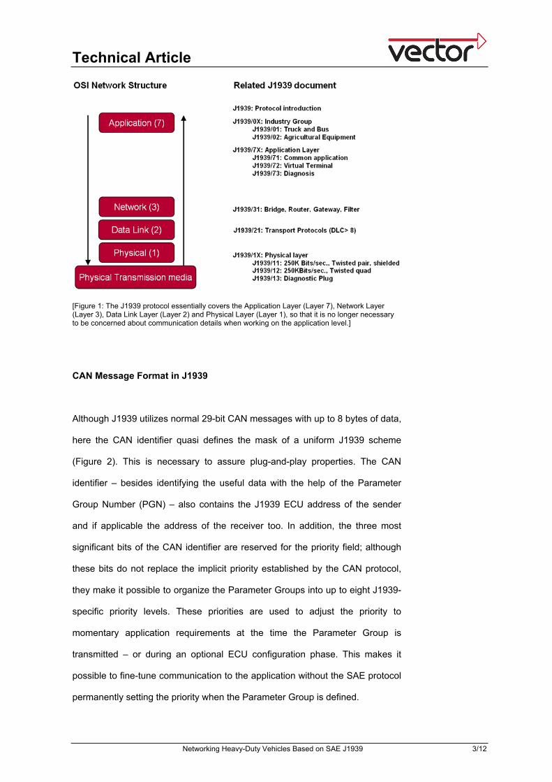
From the perspective of the ISO/OSI network model, J1939 is essentially based
on the Application Layer (Layer 7), Network Layer (Layer 3), Data Link Layer
(Layer 2) and Physical Layer (Layer 1) (Figure 1). This lets developers work
with signals without needing to be concerned about communication details on
the Application Level, such as details of the transport protocols. J1939
documentation and definition is oriented toward individual layers, and this is
expressed in the names of the total of 14 documents of the standard. For
example, documents of the 7 series such as “J1939/71” refer to the Applications
Layer, document J1939/21 the Data Link Layer, etc.
Technical Article
Networking Heavy-Duty Vehicles Based on SAE J1939 3/12
[Figure 1: The J1939 protocol essentially covers the Application Layer (Layer 7), Network Layer (Layer 3), Data Link Layer (Layer 2) and Physical Layer (Layer 1), so that it is no longer necessary to be concerned about communication details when working on the application level.]
CAN Message Format in J1939
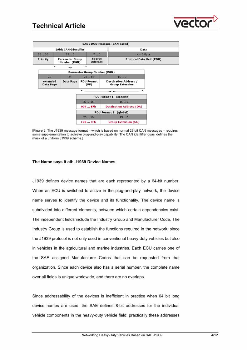
Although J1939 utilizes normal 29-bit CAN messages with up to 8 bytes of data,
here the CAN identifier quasi defines the mask of a uniform J1939 scheme
(Figure 2). This is necessary to assure plug-and-play properties. The CAN
identifier – besides identifying the useful data with the help of the Parameter
Group Number (PGN) – also contains the J1939 ECU address of the sender
and if applicable the address of the receiver too. In addition, the three most
significant bits of the CAN identifier are reserved for the priority field; although
these bits do not replace the implicit priority established by the CAN protocol,
they make it possible to organize the Parameter Groups into up to eight J1939-
specific priority levels. These priorities are used to adjust the priority to
momentary application requirements at the time the Parameter Group is
transmitted – or during an optional ECU configuration phase. This makes it
possible to fine-tune communication to the application without the SAE protocol
permanently setting the priority when the Parameter Group is defined.
Technical Article
Networking Heavy-Duty Vehicles Based on SAE J1939 4/12
[Figure 2: The J1939 message format – which is based on normal 29-bit CAN messages – requires some supplementation to achieve plug-and-play capability. The CAN identifier quasi defines the mask of a uniform J1939 scheme.]
The Name says it all: J1939 Device Names
J1939 defines device names that are each represented by a 64-bit number.
When an ECU is switched to active in the plug-and-play network, the device
name serves to identify the device and its functionality. The device name is
subdivided into different elements, between which certain dependencies exist.
The independent fields include the Industry Group and Manufacturer Code. The
Industry Group is used to establish the functions required in the network, since
the J1939 protocol is not only used in conventional heavy-duty vehicles but also
in vehicles in the agricultural and marine industries. Each ECU carries one of
the SAE assigned Manufacturer Codes that can be requested from that
organization. Since each device also has a serial number, the complete name
over all fields is unique worldwide, and there are no overlaps.
Since addressability of the devices is inefficient in practice when 64 bit long
device names are used, the SAE defines 8-bit addresses for the individual
vehicle components in the heavy-duty vehicle field; practically these addresses
Technical Article
Networking Heavy-Duty Vehicles Based on SAE J1939 5/12
never change over the life of the components. This does not apply to the
agricultural and marine industries; there the addresses are dynamically
negotiated at the start, based on the device name. The addresses 0 to 127 are
assigned to the most commonly used ECUs such as engine, transmission,
retarder, brakes, etc., while the range from 128 to 247 is reserved for
agricultural, marine, construction equipment, etc. Service tools, OBD scanners,
etc. occupy addresses from 248 to 253. Finally, there are the special
addresses: 254 to identify devices that do not have their own address and 255
that is used as a global address for addressing broadcast messages.
Types of Communication: Point-to-Point or Broadcast
The J1939 protocol supports two communication types: point-to-point
transmissions (1:1) are directed to precisely one target address; they are used
for device configuration or ECU commands, for example. Broadcast messages
(1:n), on the other hand, are simultaneously addressed to all bus nodes, which
is practical when it comes to sending out measured values, error handling and
diagnostic purposes.
Flexible Network Topology
J1939 works with a passive bus that is terminated at each of its two ends with
120 Ohm impedance. The advantage here is that individual ECUs can be
connected to the bus via branch lines with a length of 1 to 3 m. This enables
flexible wire harness design, provided that a total bus length of 40 m is not
exceeded. Depending on the physical transmission layer, between 10 and a
maximum of 30 nodes may be connected to the network. J1939 provides
uniform diagnostic access for service testers and on-board diagnostics. Legal
requirements specify that a branch line with a length of up to 5 m must be
possible here, e.g. for road tests of the emissions control system. Bridges can
Technical Article
Networking Heavy-Duty Vehicles Based on SAE J1939 6/12
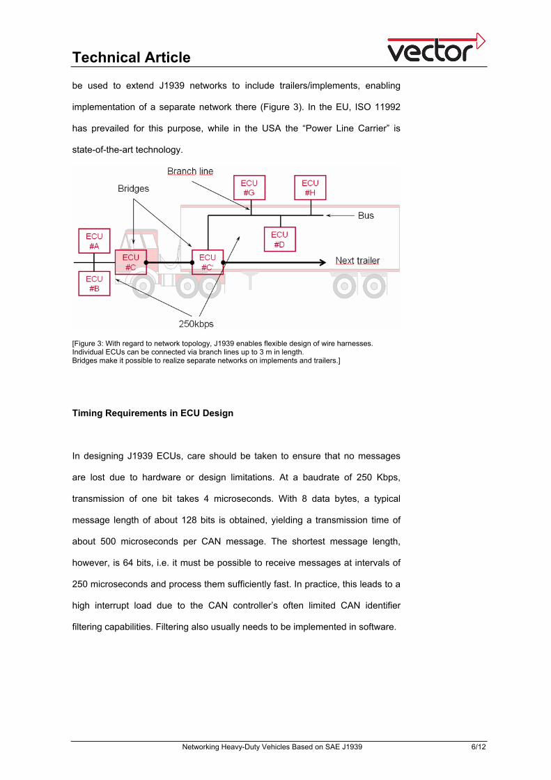
be used to extend J1939 networks to include trailers/implements, enabling
implementation of a separate network there (Figure 3). In the EU, ISO 11992
has prevailed for this purpose, while in the USA the “Power Line Carrier” is
state-of-the-art technology.
[Figure 3: With regard to network topology, J1939 enables flexible design of wire harnesses. Individual ECUs can be connected via branch lines up to 3 m in length. Bridges make it possible to realize separate networks on implements and trailers.]
Timing Requirements in ECU Design
In designing J1939 ECUs, care should be taken to ensure that no messages
are lost due to hardware or design limitations. At a baudrate of 250 Kbps,
transmission of one bit takes 4 microseconds. With 8 data bytes, a typical
message length of about 128 bits is obtained, yielding a transmission time of
about 500 microseconds per CAN message. The shortest message length,
however, is 64 bits, i.e. it must be possible to receive messages at intervals of
250 microseconds and process them sufficiently fast. In practice, this leads to a
high interrupt load due to the CAN controller’s often limited CAN identifier
filtering capabilities. Filtering also usually needs to be implemented in software.
Technical Article
Networking Heavy-Duty Vehicles Based on SAE J1939 7/12
Testing and Diagnostics of J1939 Components and Systems
In view of the rising number of J1939 ECUs and the fact that software solutions
in heavy-duty vehicles are becoming increasingly complex, a systematic
strategy for testing and diagnostics also continues to gain in importance in the
J1939 field. Tests are indispensable in all development phases, from functional
tests to integration tests to driving trials in the total vehicle. It is well known that
the later that errors are detected, the more complicated and expensive it is to
correct them. However, it is generally only possible to test ECUs
comprehensively after they have been integrated in the network structure.
Consequently, weak points are often not revealed until very late, unless one
relies on the support of proven software tools right from the start.
Given this situation, the use of specialized tools offers developers substantial
simplifications in testing and diagnostic tasks. For many years now, Vector has
been actively involved in SAE J1939 subcommittees and regularly participates
in working sessions. With a universal tool chain for all J1939 projects, it is
possible to efficiently solve the most challenging tasks in networking and
communication in the heavy-duty vehicle field [1]. Besides development, testing
and analysis tools, embedded software components tailored to the special
requirements of J1939-based applications are available, and customized
project work and training events round out Vector’s products and services.
A J1939 extension is available for the widely used CANoe development and
test tool; it spares heavy-duty vehicle developers from needing to train in the
details of the J1939 protocol. The package from Vector extends basic software
functionality to cover all necessary protocol-specific features. When
CANoe.J1939 is used consistently, the models and databases created in the
design phase not only serve as a foundation for simulation during development,
but also for all tests accompanying development up to and including later
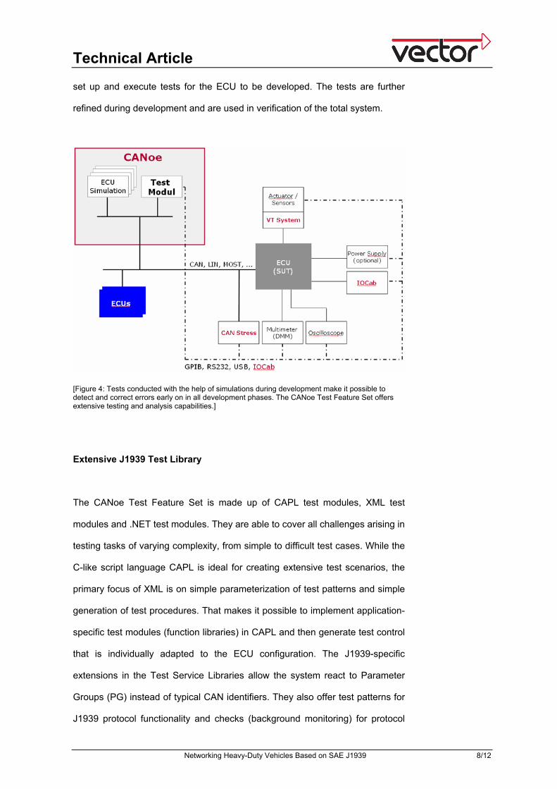
diagnostic tasks (Figure 4). With the help of simulated nodes, it is possible to
Technical Article
Networking Heavy-Duty Vehicles Based on SAE J1939 8/12
set up and execute tests for the ECU to be developed. The tests are further
refined during development and are used in verification of the total system.
[Figure 4: Tests conducted with the help of simulations during development make it possible to detect and correct errors early on in all development phases. The CANoe Test Feature Set offers extensive testing and analysis capabilities.]
Extensive J1939 Test Library
The CANoe Test Feature Set is made up of CAPL test modules, XML test
modules and .NET test modules. They are able to cover all challenges arising in
testing tasks of varying complexity, from simple to difficult test cases. While the
C-like script language CAPL is ideal for creating extensive test scenarios, the
primary focus of XML is on simple parameterization of test patterns and simple
generation of test procedures. That makes it possible to implement application-
specific test modules (function libraries) in CAPL and then generate test control
that is individually adapted to the ECU configuration. The J1939-specific
extensions in the Test Service Libraries allow the system react to Parameter
Groups (PG) instead of typical CAN identifiers. They also offer test patterns for
J1939 protocol functionality and checks (background monitoring) for protocol
Technical Article
Networking Heavy-Duty Vehicles Based on SAE J1939 9/12
violations. For example, it is possible to test whether the ECU is able to send all
Parameter Groups at the configured cycle time under high bus load.
Furthermore, it is possible to send faulty transmissions via the BAM (Broadcast
Announce Message) and CMDT (Connection Mode Data Transfer) transport
protocols for test purposes.
To create the test modules – besides the J1939 Test Module Manager and the
convenient Test Automation Editor – the Option DiVa is useful. DiVa creates a
connection between CANoe and the diagnostic specification tool
CANdelaStudio, so that specifications created there can be ideally used in
further ECU-specific diagnostic tests.
Other functions of the Test Feature Set relate to test flow control and automatic
report generation, including statistical information in XML or HTML format
based to individual requirements. Further options for automating test processes
are enabled by the COM interface, e.g. options relating to flow control,
parameter changes or status queries. CANoe Option J1939 provides a trace
window, J1939 diagnostic monitor and J1939 diagnostic memory access for
diagnostic purposes. The diagnostic monitor supports various J1939 diagnostic
messages, such as DM1 and DM2, and it serves to display and clear active
errors. Also possible is access to memory areas, objects and parameters as
well as periodic object updating for monitoring purposes.
Integrating Matlab/Simulink Models in J1939 Network Simulations
Generally, various function models are created for mechanical components
such as transmission, powertrain or even the entire vehicle during the different
heavy-duty vehicle development phases. ECU architectures are initially saved
in virtual CANoe function models and are implemented step-by-step on the final
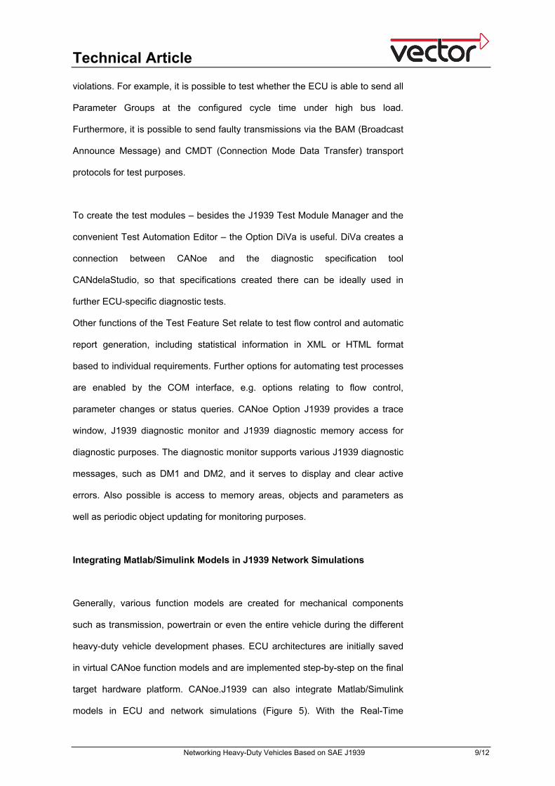
target hardware platform. CANoe.J1939 can also integrate Matlab/Simulink
models in ECU and network simulations (Figure 5). With the Real-Time
Technical Article
Networking Heavy-Duty Vehicles Based on SAE J1939 10/12
Workshop from Mathworks the user generates a *.DLL for CANoe so that
variable names and units are compatible.
[Figure 5: Not only is CANoe able to simulate functional models of ECUs during the development process and integrate models created with Matlab/Simulink in the scenarios; at the same time it also serves as a convenient user-interface. (Source: Renault Trucks)]
Progressing through the various stages of the V development model, individual
tests and subsystem tests are possible through final verification of the overall
system. This enables early detection and correction of errors. If an error is
found, the automated tests can be restarted at any time; they minimize the risk
of side effects in error correction. As a result, development is characterized by
short verification cycles, enabling a seamless transition from MIL (Model in the
loop) to SIL (Software in the loop) and then to the real ECU (HIL – Hardware in
the loop). If there are exceptional real-time requirements of the simulation
platform, a special real-time version is available with CANoe RT.
Technical Article
Networking Heavy-Duty Vehicles Based on SAE J1939 11/12
Realizing Goals quickly with standardized Embedded Software
Components
Use of CANbedded J1939 software components leads to quick development
results. These components largely relieve developers of the need to handle all
of the details of the J1939 standard, and they avoid duplicated developments. A
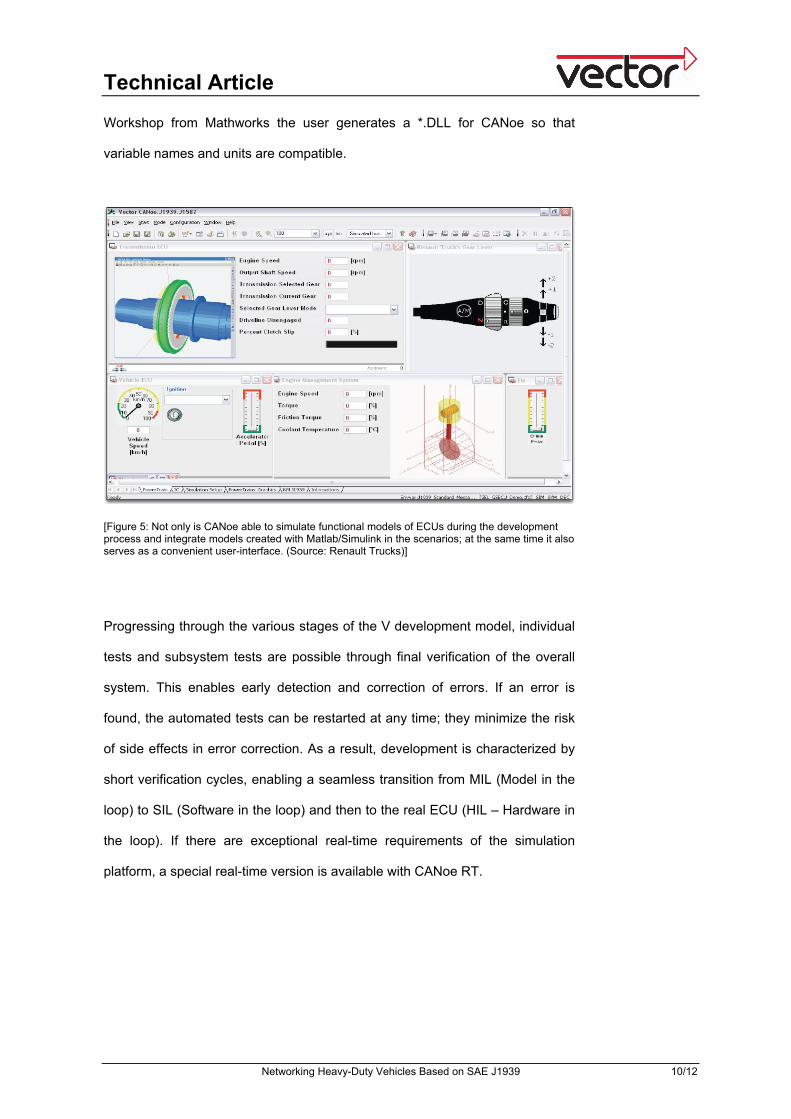
key aspect is a central OEM-managed database containing all elementary
information related to ECU communication. Depending on requirements, this
information might be distributed to other working partners, producing flexible
distribution of tasks between the OEM, network specialists from Vector and
suppliers (Figure 6). The latter can use the GENy configuration tool for specific
settings and parameterizations. The results are reduced cost and timing for
implementation and testing, compatibility on the CAN bus based on
unambiguous signal interpretation and maximum quality and flexibility in the
J1939 communication stack. CANbedded J1939 supports all relevant
microcontrollers and is characterized by low ROM and RAM memory
requirements as well as high runtime efficiency.
[Figure 6: Standard software components of the CANbedded J1939 package lead to quick development results without developers needing to be concerned with all details of the J1939 standard. A centrally managed database avoids duplicated developments and enables optimal work distribution.]
Technical Article
Networking Heavy-Duty Vehicles Based on SAE J1939 12/12
Revised: 9/2008 Word count: 2,473 Character count: 16,070 Figures: Source reference: Figures 0-4, 6: Vector Informatik GmbH Figure 5: Renault Trucks Internet links: [1] J1939 solutions from Vector - www.j1939-solutions.com [2] Download of presentations from J1939 User Day - www.vector-worldwide.com/ud [most of them are German] Authors:
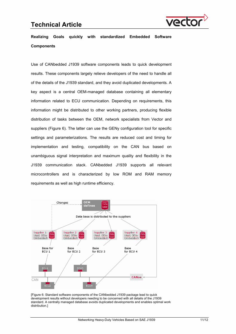
Peter Fellmeth studied at the University of Applied Sciences in Esslingen, Germany, majoring in Computer Engineering and specializing in Automation Technology. He is team leader and product manager at Vector Informatik GmbH, where he is responsible for the development of products and customer-specific projects related to J1939, ISOBUS, Ethernet and DeviceNet.
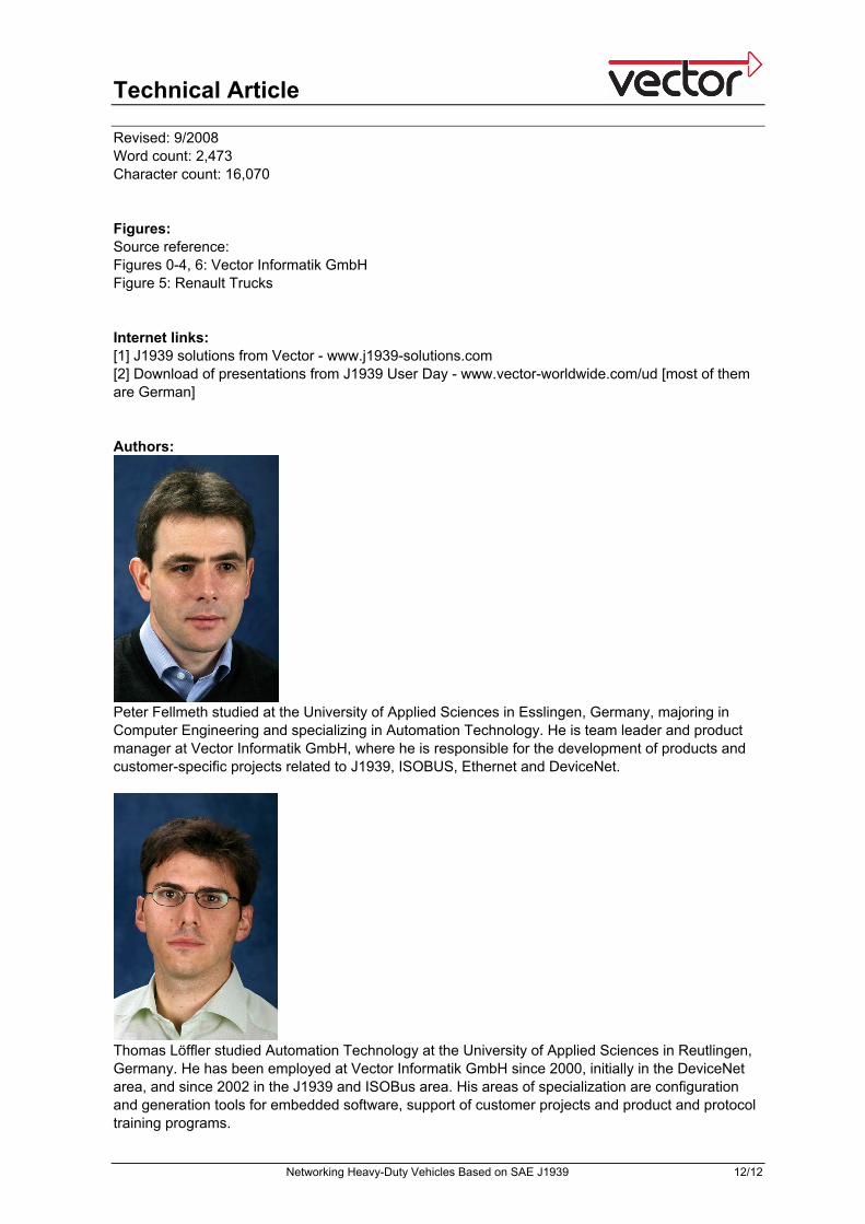
Thomas Löffler studied Automation Technology at the University of Applied Sciences in Reutlingen, Germany. He has been employed at Vector Informatik GmbH since 2000, initially in the DeviceNet area, and since 2002 in the J1939 and ISOBus area. His areas of specialization are configuration and generation tools for embedded software, support of customer projects and product and protocol training programs.