Embed Size (px)
Citation preview
10 CAN Newsletter 4/2018
Heavy-duty commercial and off-highway vehicles, such as agricultural and construction equipment, pose mul-
tiple electrical and mechanical engineering challenges. These vehicles must be efficient, durable, and reliable as they have long service lives in strenuous environmen-tal conditions that can include extreme temperature, dirt, dust, and altitude.
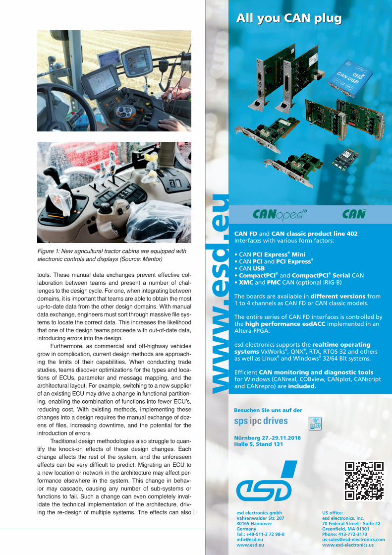
The challenge of designing commercial and off-high-way vehicles is mounting as the electrical systems grow in size and sophistication. Several interconnected networks of electronic control units (ECUs), sensors, and actuators moni-tor and control the critical systems in modern vehicles. This system of ECUs is constantly measuring suspect parameters (sometimes also referred as signals) such as temperature, pressure, and position of various components. This system also controls the activation of electrical and hydraulic actua-tors, engine, and driveline ancillaries, and much more. The increasing systems complexity of commercial and off-high-way vehicles is similarly evident in the cabin. Agricultural trac-tors, for example, now feature electronic and digital controls as well as cabin amenities like heated seats and climate con-trol systems (Figure 1).
Engineers must determine how to manage the commu-nications and connectivity between the various electrical and electronic components. Therefore, one of the first steps for new vehicle design is defining the electrical and electronic (E/E) architecture. In the definition stage, engineers evalu-ate various proposals for the layout of the new vehicle and conduct trade studies to determine the quantity, type, and location of the necessary ECUs to enable the functionality required for the desired vehicle features. The architectural design data can then feed the downstream electrical, net-work, software, and hardware implementation.
A key consideration during commercial and off-high-way E/E architectural definition is the SAE J1939 specifica-tion series for communications between ECUs in the vehicle. J1939 is a higher-layer protocol (HLP) for communications across the CAN network that provides standardized applica-tion layer messages and conversion rules across commer-cial, off-highway, and heavy-duty manufacturers. These rules support interoperability between manufacturers and imple-mentations, such as between tractor unit and trailer.
SAE J1939DA is comprised of a set of parameter group (PGs) and suspect parameter (SPs). The PG identifies the set of related parameters the communication is addressing, and the SP identifies a specific parameter within the group. For example, there is a PG identifying data related to engine temperature. Within that PG, there are SPs to identify spe-cific temperature data for the engine coolant, fuel, oil, turbo-charger oil, and intercooler.
Since its creation, J1939 has become widely adopted in heavy-duty road vehicles and off-highway applications such as commercial semi-trucks and construction equipment. A number of derivatives of the standard have also been devel-oped for agricultural, forestry, and marine applications, as well as for interfacing with fleet management systems. With the growth of the IoT and connected vehicles, J1939 net-works becomes more important as trucks, busses, and other large vehicles began to communicate with each other and into the cloud.
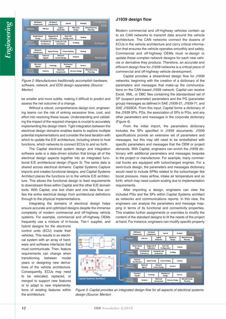
Traditionally, heavy duty commercial and off-highway vehicle manufacturers have taken a separated approach to electrical design that creates silos for hardware, software, networks, and electrical distribution system (EDS) design (Figure 2). Teams work separately and exchange data man-ually using email, marked-up PDF files, or Microsoft Office
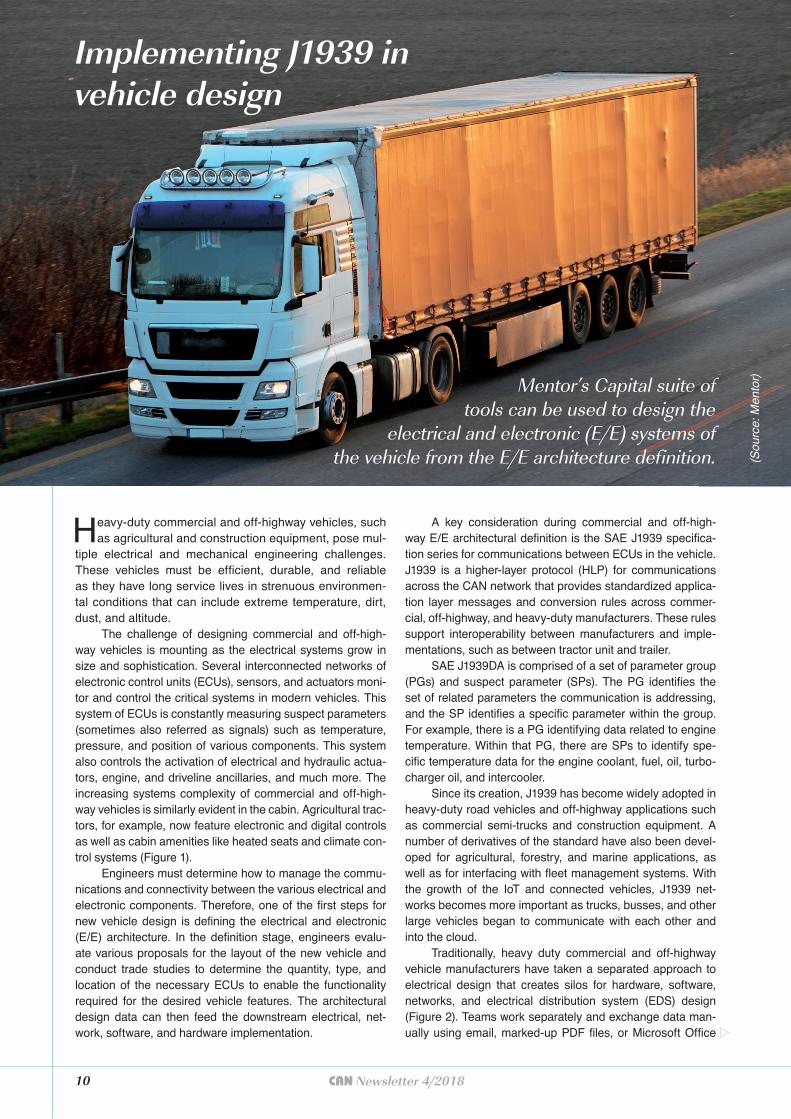
Implementing J1939 invehicle design
Mentor’s Capital suite of tools can be used to design the
electrical and electronic (E/E) systems of the vehicle from the E/E architecture definition. (S
ourc
e: M
ento
r)
tools. These manual data exchanges prevent effective col-laboration between teams and present a number of chal-lenges to the design cycle. For one, when integrating between domains, it is important that teams are able to obtain the most up-to-date data from the other design domains. With manual data exchange, engineers must sort through massive file sys-tems to locate the correct data. This increases the likelihood that one of the design teams proceede with out-of-date data, introducing errors into the design.
Furthermore, as commercial and off-highway vehicles grow in complication, current design methods are approach-ing the limits of their capabilities. When conducting trade studies, teams discover optimizations for the types and loca-tions of ECUs, parameter and message mapping, and the architectural layout. For example, switching to a new supplier of an existing ECU may drive a change in functional partition-ing, enabling the combination of functions into fewer ECU’s, reducing cost. With existing methods, implementing these changes into a design requires the manual exchange of doz-ens of files, increasing downtime, and the potential for the introduction of errors.
Traditional design methodologies also struggle to quan-tify the knock-on effects of these design changes. Each change affects the rest of the system, and the unforeseen effects can be very difficult to predict. Migrating an ECU to a new location or network in the architecture may affect per-formance elsewhere in the system. This change in behav-ior may cascade, causing any number of sub-systems or functions to fail. Such a change can even completely inval-idate the technical implementation of the architecture, driv-ing the re-design of multiple systems. The effects can also
Figure 1: New agricultural tractor cabins are equipped with electronic controls and displays (Source: Mentor)
12 CAN Newsletter 4/2018
be smaller and more subtle, making it difficult to predict and assess the net outcome of a change.
Without a robust, comprehensive design tool, engineer-ing teams run the risk of sinking excessive time, cost, and effort into resolving these issues. Understanding and validat-ing the impact of the required changes is crucial to accurately implementing the design intent. Tight integration between the electrical design domains enables teams to explore multiple potential implementations and consider the best iteration with which to update the E/E architecture, including where to host functions, which networks to connect ECUs to and so forth.
The Capital electrical system design and integration software suite is a data-driven solution that brings all of the electrical design aspects together into an integrated func-tional E/E architectural design (Figure 3). The same data is shared across electrical domains: Capital Systems Capture imports and creates functional designs, and Capital Systems Architect places the functions on to the vehicle E/E architec-ture. This allows the functional design to feed requirements to downstream flows within Capital and the other E/E domain tools. With Capital, one tool chain and one data flow uni-fies the entire electrical design from architectural definitions through to the physical implementations.
Integrating the domains of electrical design helps ensure accurate and optimized designs despite the immense complexity of modern commercial and off-highway vehicle systems. For example, commercial and off-highway OEMs frequently use a mixture of in-house, Tier-1 supplier, and hybrid designs for the electronic control units (ECU) inside their vehicles. This results in an electri-cal system with an array of hard-ware and software interfaces that must communicate. Then, feature requirements can change when transitioning between model years or designing new deriva-tives of the vehicle architecture. Consequently, ECUs may need to be relocated, replaced, or merged to support new features or to adapt to new implementa-tions of existing features within the architecture.
J1939 design flow
Modern commercial and off-highway vehicles contain up to six CAN networks to transmit data around the vehicle architecture. The CAN networks connect the dozens of ECUs in the vehicle architecture and carry critical informa-tion that ensures the vehicle operates smoothly and safely. Commercial and off-highway OEMs must re-design or update these complex network designs for each new vehi-cle or derivative they produce. Therefore, an accurate and efficient design flow for J1939 networks is a critical piece of commercial and off-highway vehicle development.
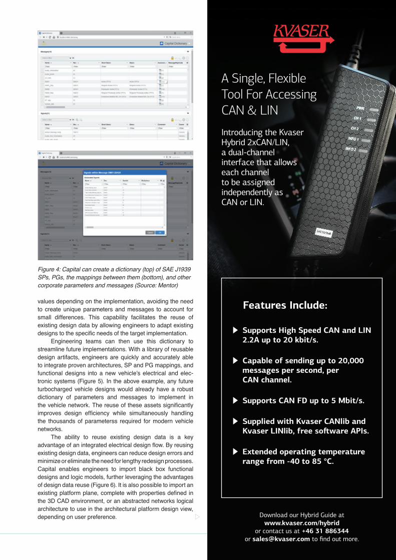
Capital provides a streamlined design flow for J1939 networks, beginning with the creation of a dictionary of the parameters and messages that make-up the communica-tions on the CAN-based J1939 network. Capital can receive Excel, XML, or DBC files containing the standardized set of SP (suspect parameter) parameters and the PG (parameter group) messages as defined in SAE J1939-21, J1939-71, and SAE J1939DA. From this input, Capital forms a dictionary of the J1939 SPs, PGs, the association of SPs to PGs, and any other parameters and messages in the corporate dictionary (Figure 4).
From the initial import, the parameters dictionary includes the SPs specified in J1939 documents. J1939 specifications provide an extensive set of parameters and messages, but this may still need to be embellished with specific parameters and messages that the OEM or project demands. With Capital, engineers can enrich the J1939 dic-tionary with additional parameters and messages bespoke to the project or manufacturer. For example, many commer-cial trucks are equipped with turbocharged engines. For a semi-truck design, the parameters and messages dictionary would need to include SPNs related to the turbocharger like boost pressure, mass airflow, intake air temperature and so forth, which may need custom scaling due to implementation requirements.
After importing a design, engineers can view the included PGs and the SPs within Capital Systems architect as networks and communications reports. In this view, the engineers can analyze the parameters and message map-ping in terms of its functional and connectivity properties. This enables further assignments or overrides to modify the content of the standard designs to fit the needs of the project at hand. For instance, engineers can modify specific property
Figure 2: Manufacturers traditionally accomplish hardware, software, network, and EDS design separately (Source: Mentor)
Figure 3: Capital provides an integrated design flow for all aspects of electrical systems design (Source: Mentor)
Engi
neer
ing
Features Include:
Supports High Speed CAN and LIN 2.2A up to 20 kbit/s.
Capable of sending up to 20,000 messages per second, per CAN channel.
Supports CAN FD up to 5 Mbit/s.
Supplied with Kvaser CANlib and
Extended operating temperature range from -40 to 85 °C.
A Single, FlexibleTool For AccessingCAN & LIN
Introducing the Kvaser Hybrid 2xCAN/LIN, a dual-channel interface that allows each channel to be assigned independently as CAN or LIN.
Download our Hybrid Guide at www.kvaser.com/hybrid
or contact us at +46 31 886344 or [email protected]
values depending on the implementation, avoiding the need to create unique parameters and messages to account for small differences. This capability facilitates the reuse of existing design data by allowing engineers to adapt existing designs to the specific needs of the target implementation.
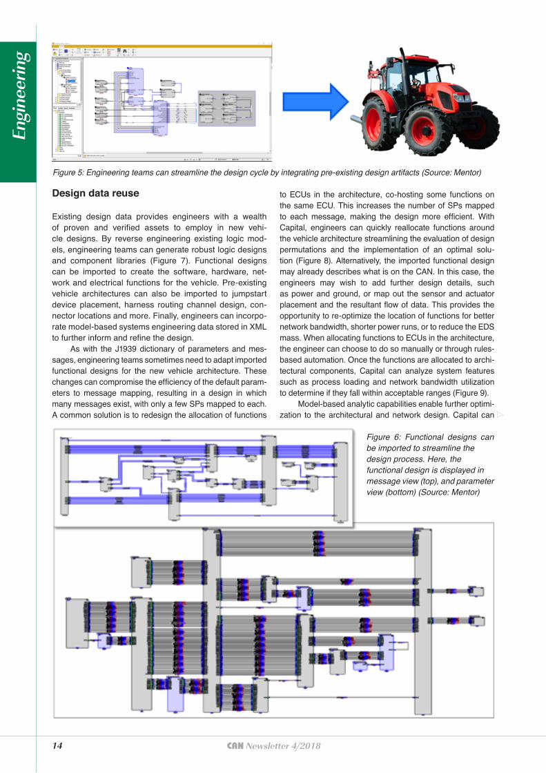
Engineering teams can then use this dictionary to streamline future implementations. With a library of reusable design artifacts, engineers are quickly and accurately able to integrate proven architectures, SP and PG mappings, and functional designs into a new vehicle’s electrical and elec-tronic systems (Figure 5). In the above example, any future turbocharged vehicle designs would already have a robust dictionary of parameters and messages to implement in the vehicle network. The reuse of these assets significantly improves design efficiency while simultaneously handling the thousands of parameterss required for modern vehicle networks.
The ability to reuse existing design data is a key advantage of an integrated electrical design flow. By reusing existing design data, engineers can reduce design errors and minimize or eliminate the need for lengthy redesign processes. Capital enables engineers to import black box functional designs and logic models, further leveraging the advantages of design data reuse (Figure 6). It is also possible to import an existing platform plane, complete with properties defined in the 3D CAD environment, or an abstracted networks logical architecture to use in the architectural platform design view, depending on user preference.
Figure 4: Capital can create a dictionary (top) of SAE J1939 SPs, PGs, the mappings between them (bottom), and other corporate parameters and messages (Source: Mentor)
14 CAN Newsletter 4/2018
Design data reuse
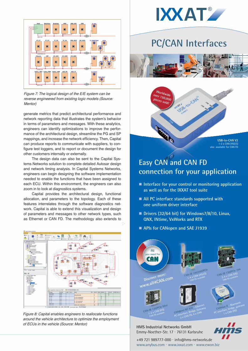
Existing design data provides engineers with a wealth of proven and verified assets to employ in new vehi-cle designs. By reverse engineering existing logic mod-els, engineering teams can generate robust logic designs and component libraries (Figure 7). Functional designs can be imported to create the software, hardware, net-work and electrical functions for the vehicle. Pre-existing vehicle architectures can also be imported to jumpstart device placement, harness routing channel design, con-nector locations and more. Finally, engineers can incorpo-rate model-based systems engineering data stored in XML to further inform and refine the design.
As with the J1939 dictionary of parameters and mes-sages, engineering teams sometimes need to adapt imported functional designs for the new vehicle architecture. These changes can compromise the efficiency of the default param-eters to message mapping, resulting in a design in which many messages exist, with only a few SPs mapped to each. A common solution is to redesign the allocation of functions
Figure 5: Engineering teams can streamline the design cycle by integrating pre-existing design artifacts (Source: Mentor)
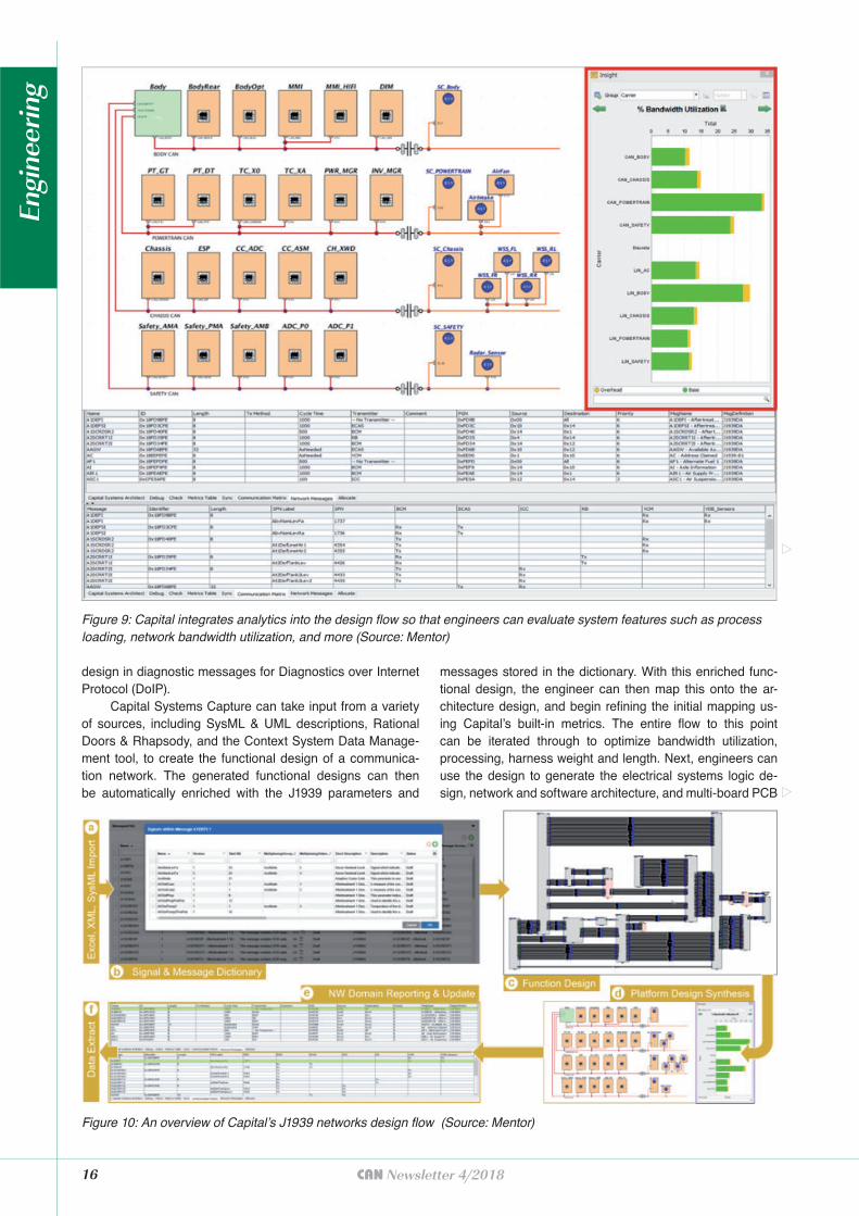
to ECUs in the architecture, co-hosting some functions on the same ECU. This increases the number of SPs mapped to each message, making the design more efficient. With Capital, engineers can quickly reallocate functions around the vehicle architecture streamlining the evaluation of design permutations and the implementation of an optimal solu-tion (Figure 8). Alternatively, the imported functional design may already describes what is on the CAN. In this case, the engineers may wish to add further design details, such as power and ground, or map out the sensor and actuator placement and the resultant flow of data. This provides the opportunity to re-optimize the location of functions for better network bandwidth, shorter power runs, or to reduce the EDS mass. When allocating functions to ECUs in the architecture, the engineer can choose to do so manually or through rules-based automation. Once the functions are allocated to archi-tectural components, Capital can analyze system features such as process loading and network bandwidth utilization to determine if they fall within acceptable ranges (Figure 9).
Model-based analytic capabilities enable further optimi-zation to the architectural and network design. Capital can
Figure 6: Functional designs can be imported to streamline the design process. Here, the functional design is displayed inmessage view (top), and parameter view (bottom) (Source: Mentor)
Engi
neer
ing
HMS Industrial Networks GmbHEmmy-Noether-Str. 17 · 76131 Karlsruhe
+49 721 989777-000 · [email protected] www.anybus.com · www.ixxat.com · www.ewon.biz
PC/CAN Interfaces
CANblue II - Bluetooth
PC interface, bridge, gateway
1 x CAN (HS)CAN-IB 120/PCIe Mini
1-2 x CAN (HS)
CAN FD available
CAN-IB 100/200/PCIe
1-4 x CAN (HS/LS)
CAN FD availableCAN-IB 130/PCIe 104
2-4 x CAN (HS)
CAN FD available
Easy CAN and CAN FD connection for your application
Interface for your control or monitoring application as well as for the IXXAT tool suite
All PC interface standards supported with one uniform driver interface
Drivers (32/64 bit) for Windows7/8/10, Linux, QNX, INtime, VxWorks and RTX
APIs for CANopen and SAE J1939
CANA BBB-IB 1000/20 00/
CAN (HS/
Discover more:
www.all4CAN.com
All you need for
ver mmore:
AlAlAllllyyyoouu need fofor
USB-to-CAN V21-2 x CAN (HS/LS)
also available for CAN FD
CAN@net NT 420 - Ethernet
PC-Interface, Bridge, Gateway
2 x CAN FD, 4 x CAN
Worldwide over 150,000 pieces sold!
generate metrics that predict architectural performance and network reporting data that illustrates the system’s behavior in terms of parameters and messages. With these analytics, engineers can identify optimizations to improve the perfor-mance of the architectural design, streamline the PG and SP mappings, and increase the network efficiency. Then, Capital can produce reports to communicate with suppliers, to con-figure test loggers, and to report or document the design for other customers internally or externally.
The design data can also be sent to the Capital Sys-tems Networks solution to complete detailed Autosar design and network timing analysis. In Capital Systems Networks, engineers can begin designing the software implementation needed to enable the functions that have been assigned to each ECU. Within this environment, the engineers can also zoom in to look at diagnostics systems.
Capital provides the architectural design, functional allocation, and parameters to the topology. Each of these features interrelates through the software diagnostics net-work. Capital is able to extend this visualization and design of parameters and messages to other network types, such as Ethernet or CAN FD. The methodology also extends to
Figure 7: The logical design of the E/E system can be reverse engineered from existing logic models (Source: Mentor)
Figure 8: Capital enables engineers to reallocate functions around the vehicle architecture to optimize the employment of ECUs in the vehicle (Source: Mentor)
16 CAN Newsletter 4/2018
design in diagnostic messages for Diagnostics over Internet Protocol (DoIP).
Capital Systems Capture can take input from a variety of sources, including SysML & UML descriptions, Rational Doors & Rhapsody, and the Context System Data Manage-ment tool, to create the functional design of a communica-tion network. The generated functional designs can then be automatically enriched with the J1939 parameters and
messages stored in the dictionary. With this enriched func-tional design, the engineer can then map this onto the ar-chitecture design, and begin refining the initial mapping us-ing Capital’s built-in metrics. The entire flow to this point can be iterated through to optimize bandwidth utilization, processing, harness weight and length. Next, engineers can use the design to generate the electrical systems logic de-sign, network and software architecture, and multi-board PCB
Figure 9: Capital integrates analytics into the design flow so that engineers can evaluate system features such as process loading, network bandwidth utilization, and more (Source: Mentor)
Figure 10: An overview of Capital’s J1939 networks design flow (Source: Mentor)
Engi
neer
ing
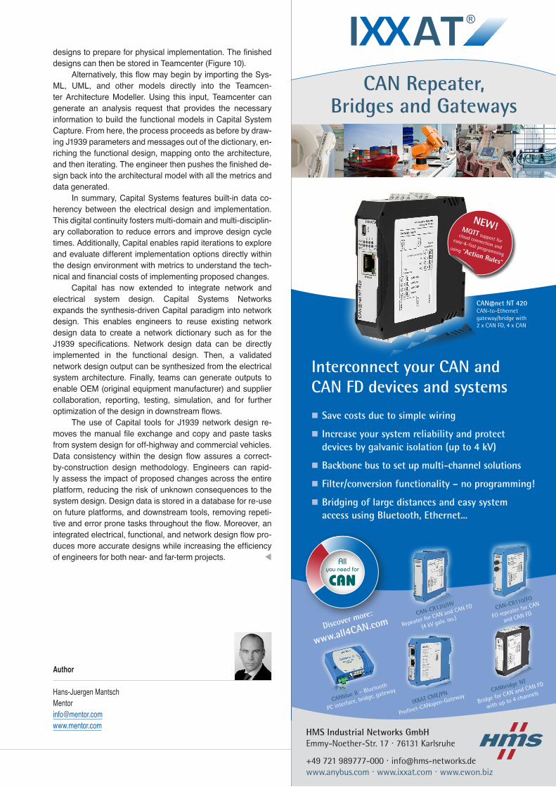
designs to prepare for physical implementation. The finished designs can then be stored in Teamcenter (Figure 10).
Alternatively, this flow may begin by importing the Sys-ML, UML, and other models directly into the Teamcen-ter Architecture Modeller. Using this input, Teamcenter can generate an analysis request that provides the necessary information to build the functional models in Capital System Capture. From here, the process proceeds as before by draw-ing J1939 parameters and messages out of the dictionary, en-riching the functional design, mapping onto the architecture, and then iterating. The engineer then pushes the finished de-sign back into the architectural model with all the metrics and data generated.
In summary, Capital Systems features built-in data co-herency between the electrical design and implementation. This digital continuity fosters multi-domain and multi-disciplin-ary collaboration to reduce errors and improve design cycle times. Additionally, Capital enables rapid iterations to explore and evaluate different implementation options directly within the design environment with metrics to understand the tech-nical and financial costs of implementing proposed changes.
Capital has now extended to integrate network and electrical system design. Capital Systems Networks expands the synthesis-driven Capital paradigm into network design. This enables engineers to reuse existing network design data to create a network dictionary such as for the J1939 specifications. Network design data can be directly implemented in the functional design. Then, a validated network design output can be synthesized from the electrical system architecture. Finally, teams can generate outputs to enable OEM (original equipment manufacturer) and supplier collaboration, reporting, testing, simulation, and for further optimization of the design in downstream flows.
The use of Capital tools for J1939 network design re-moves the manual file exchange and copy and paste tasks from system design for off-highway and commercial vehicles. Data consistency within the design flow assures a correct-by-construction design methodology. Engineers can rapid-ly assess the impact of proposed changes across the entire platform, reducing the risk of unknown consequences to the system design. Design data is stored in a database for re-use on future platforms, and downstream tools, removing repeti-tive and error prone tasks throughout the flow. Moreover, an integrated electrical, functional, and network design flow pro-duces more accurate designs while increasing the efficiency of engineers for both near- and far-term projects. t
Author
Hans-Juergen [email protected] www.mentor.com
HMS Industrial Networks GmbHEmmy-Noether-Str. 17 · 76131 Karlsruhe
+49 721 989777-000 · [email protected] www.anybus.com · www.ixxat.com · www.ewon.biz
CAN Repeater, Bridges and Gateways
CANblue II – Bluetooth
PC interface, bridge, gateway CANbridge NT
Bridge for CAN and CAN FD
with up to 4 channels
CAN-CR120/HV
Repeater for CAN and CAN FD
(4 kV galv. iso.)
CAN-CR110/FO
FO repeater for CAN
and CAN FD
IXXAT CME/PN
Profinet-CANopen-Gateway
Interconnect your CAN and CAN FD devices and systems
Save costs due to simple wiring
Increase your system reliability and protect devices by galvanic isolation (up to 4 kV)
Backbone bus to set up multi-channel solutions
Filter/conversion functionality – no programming!
Bridging of large distances and easy system access using Bluetooth, Ethernet...
CAN@net NT 420CAN-to-Ethernet gateway/bridge with 2 x CAN FD, 4 x CAN
Discover more:
www.all4CAN.com
All you need for
NEW!MQTT support for cloud connection and
easy-&-fast programming using “Action Rules“
cia_anzeigen-v4.indd 2 10.07.2018 08:40:40


![DCU 305 R3 CAN / J1939 Manual - Auto-Maskin§ [a] SAE, J1939-71 § [b] SAE, J1939-73 § [c] Conrad Etschberger, “Controller Area Network” ... CAN / J1939 Manual CAN / J1939 –](https://img.pdfslide.us/doc/110x75/5ae535d97f8b9a7b218f6863/dcu-305-r3-can-j1939-manual-auto-maskin-a-sae-j1939-71-b-sae-j1939-73.jpg)