Embed Size (px)
Citation preview
Water Pipes on Titanic’s Funnels
By Bob Read, D.M.D.
Introduction
This article is aimed at modelers of Titanic in any medium. There is no single source which has
examined the locations and types of water pipes which are attached to Titanic’s funnels. The
locations and types of these pipes are important for the modeler who wants to portray Titanic
accurately. Photos in this article will be exclusively of Titanic. This article will rely more heavily
on images than on text.
Pipe types
The pipes found on Titanic’s funnels are of two primary types:
1. Pipe loops – These simple loops are run up the funnels to supply a higher standing column
of water to the tanks which these pipes serve for the purpose of increasing the water
pressure to the tank distribution areas.
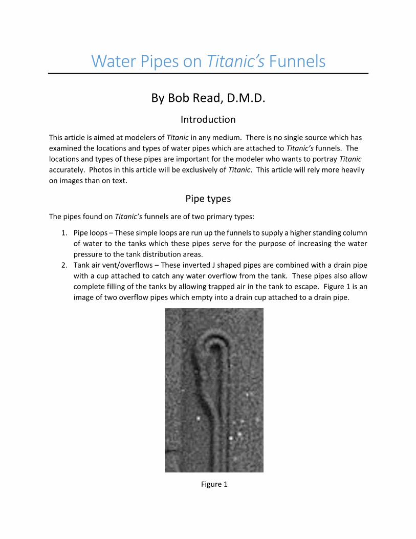
2. Tank air vent/overflows – These inverted J shaped pipes are combined with a drain pipe
with a cup attached to catch any water overflow from the tank. These pipes also allow
complete filling of the tanks by allowing trapped air in the tank to escape. Figure 1 is an
image of two overflow pipes which empty into a drain cup attached to a drain pipe.
Figure 1
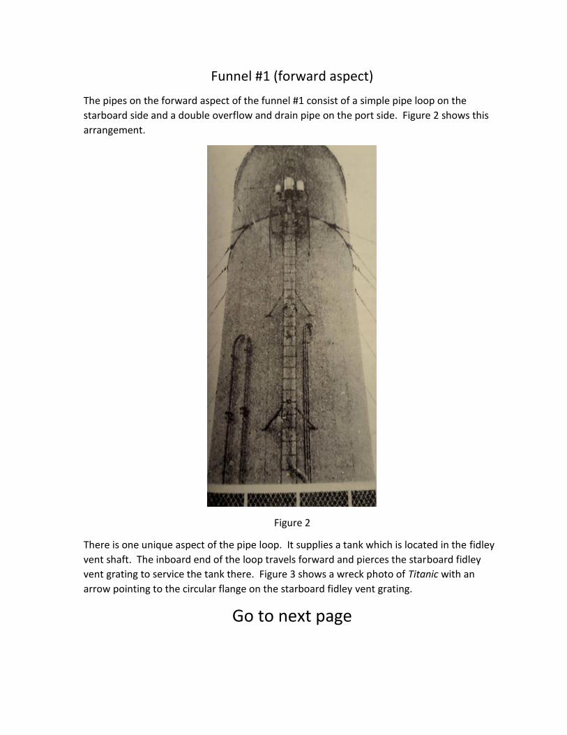
Funnel #1 (forward aspect)
The pipes on the forward aspect of the funnel #1 consist of a simple pipe loop on the
starboard side and a double overflow and drain pipe on the port side. Figure 2 shows this
arrangement.
Figure 2
There is one unique aspect of the pipe loop. It supplies a tank which is located in the fidley
vent shaft. The inboard end of the loop travels forward and pierces the starboard fidley
vent grating to service the tank there. Figure 3 shows a wreck photo of Titanic with an
arrow pointing to the circular flange on the starboard fidley vent grating.
Go to next page
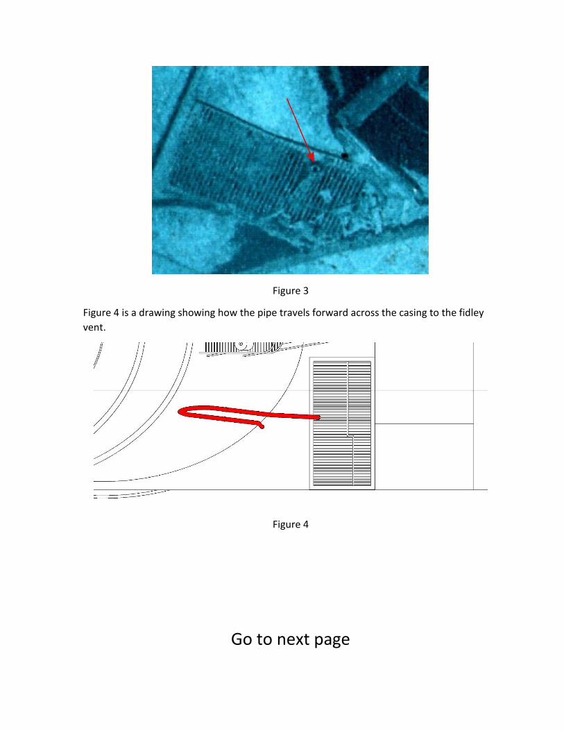
Figure 3
Figure 4 is a drawing showing how the pipe travels forward across the casing to the fidley
vent.
Figure 4
Go to next page
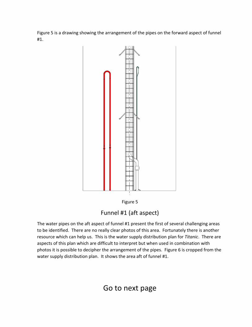
Figure 5 is a drawing showing the arrangement of the pipes on the forward aspect of funnel
#1.
Figure 5
Funnel #1 (aft aspect)
The water pipes on the aft aspect of funnel #1 present the first of several challenging areas
to be identified. There are no really clear photos of this area. Fortunately there is another
resource which can help us. This is the water supply distribution plan for Titanic. There are
aspects of this plan which are difficult to interpret but when used in combination with
photos it is possible to decipher the arrangement of the pipes. Figure 6 is cropped from the
water supply distribution plan. It shows the area aft of funnel #1.
Go to next page
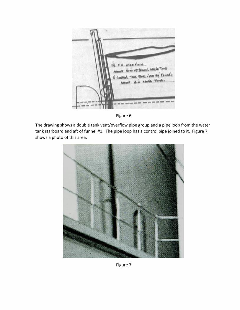
Figure 6
The drawing shows a double tank vent/overflow pipe group and a pipe loop from the water
tank starboard and aft of funnel #1. The pipe loop has a control pipe joined to it. Figure 7
shows a photo of this area.
Figure 7
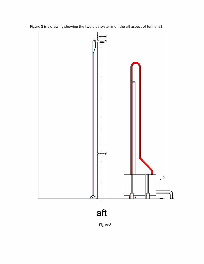
Figure 8 is a drawing showing the two pipe systems on the aft aspect of funnel #1.
Figure8
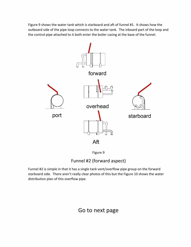
Figure 9 shows the water tank which is starboard and aft of funnel #1. It shows how the
outboard side of the pipe loop connects to the water tank. The inboard part of the loop and
the control pipe attached to it both enter the boiler casing at the base of the funnel.
Figure 9
Funnel #2 (forward aspect)
Funnel #2 is simple in that it has a single tank vent/overflow pipe group on the forward
starboard side. There aren’t really clear photos of this but the Figure 10 shows the water
distribution plan of this overflow pipe.
Go to next page
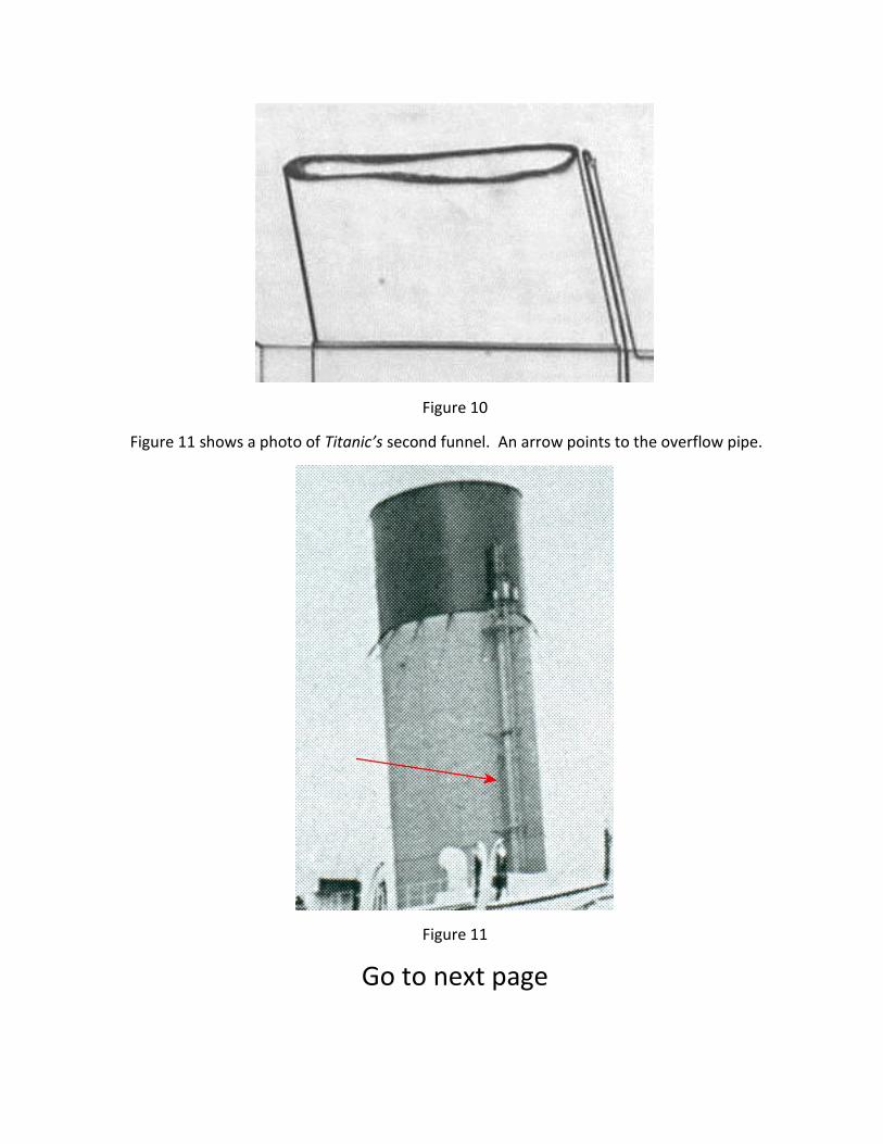
Figure 10
Figure 11 shows a photo of Titanic’s second funnel. An arrow points to the overflow pipe.
Figure 11
Go to next page
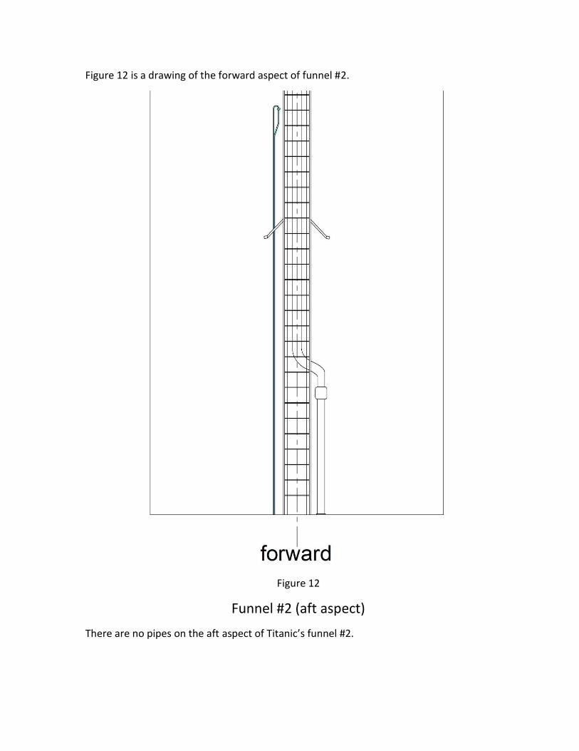
Figure 12 is a drawing of the forward aspect of funnel #2.
Figure 12
Funnel #2 (aft aspect)
There are no pipes on the aft aspect of Titanic’s funnel #2.
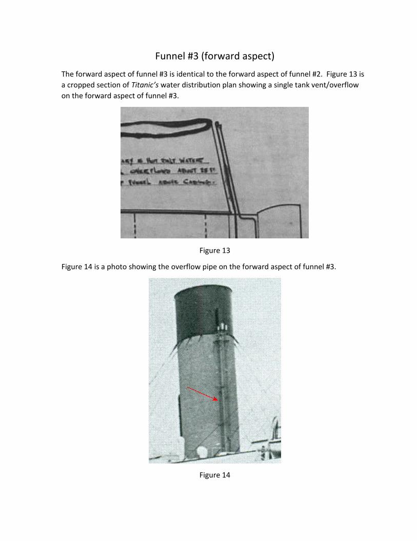
Funnel #3 (forward aspect)
The forward aspect of funnel #3 is identical to the forward aspect of funnel #2. Figure 13 is
a cropped section of Titanic’s water distribution plan showing a single tank vent/overflow
on the forward aspect of funnel #3.
Figure 13
Figure 14 is a photo showing the overflow pipe on the forward aspect of funnel #3.
Figure 14
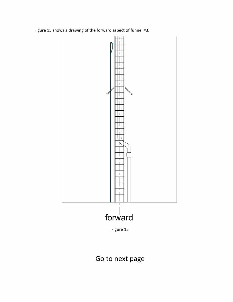
Figure 15 shows a drawing of the forward aspect of funnel #3.
Figure 15
Go to next page
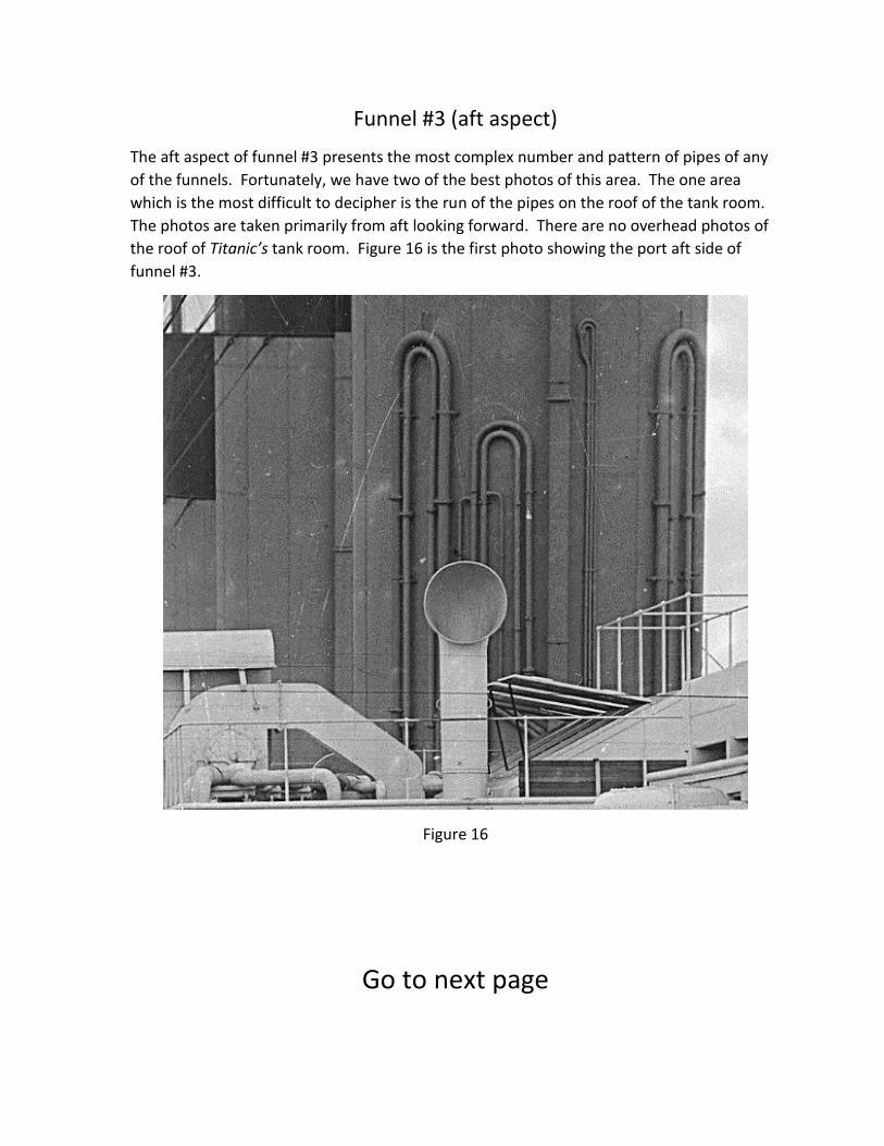
Funnel #3 (aft aspect)
The aft aspect of funnel #3 presents the most complex number and pattern of pipes of any
of the funnels. Fortunately, we have two of the best photos of this area. The one area
which is the most difficult to decipher is the run of the pipes on the roof of the tank room.
The photos are taken primarily from aft looking forward. There are no overhead photos of
the roof of Titanic’s tank room. Figure 16 is the first photo showing the port aft side of
funnel #3.
Figure 16
Go to next page
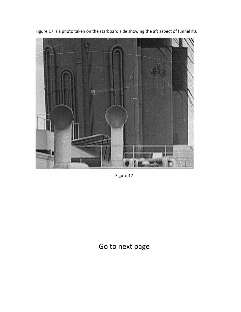
Figure 17 is a photo taken on the starboard side showing the aft aspect of funnel #3.
Figure 17
Go to next page
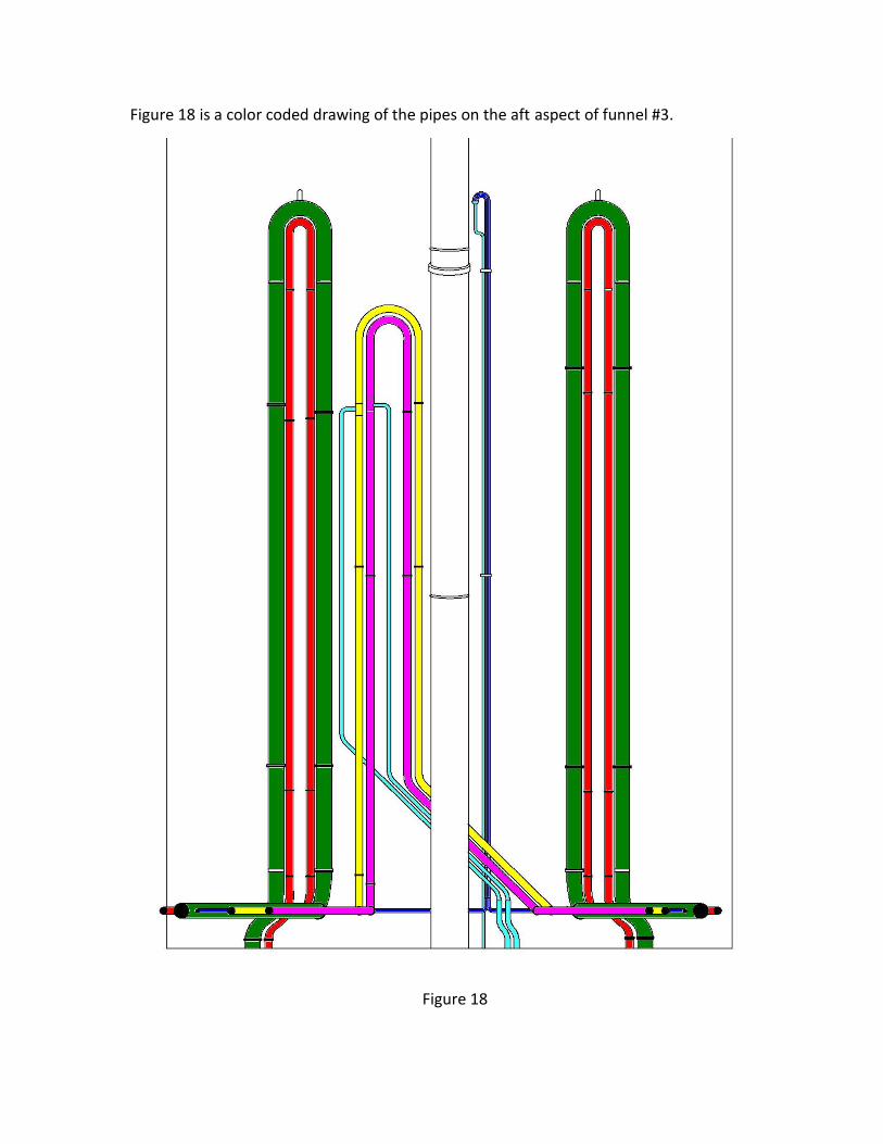
Figure 18 is a color coded drawing of the pipes on the aft aspect of funnel #3.
Figure 18
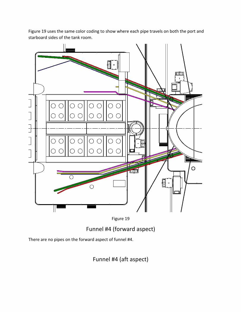
Figure 19 uses the same color coding to show where each pipe travels on both the port and
starboard sides of the tank room.
Figure 19
Funnel #4 (forward aspect)
There are no pipes on the forward aspect of funnel #4.
Funnel #4 (aft aspect)
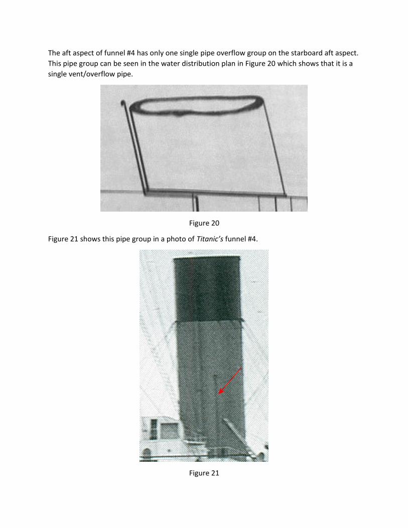
The aft aspect of funnel #4 has only one single pipe overflow group on the starboard aft aspect.
This pipe group can be seen in the water distribution plan in Figure 20 which shows that it is a
single vent/overflow pipe.
Figure 20
Figure 21 shows this pipe group in a photo of Titanic’s funnel #4.
Figure 21
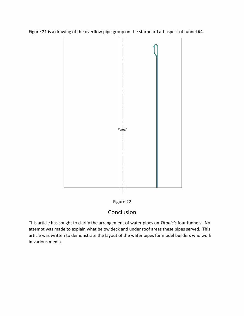
Figure 21 is a drawing of the overflow pipe group on the starboard aft aspect of funnel #4.
Figure 22
Conclusion
This article has sought to clarify the arrangement of water pipes on Titanic’s four funnels. No
attempt was made to explain what below deck and under roof areas these pipes served. This
article was written to demonstrate the layout of the water pipes for model builders who work
in various media.