Embed Size (px)
Citation preview
Revision AP/N UM600336
Assembly Instructions
Wall Mount Kit for
Elo 5553 IDS Display
© 2019 Elo Touch Solutions, Inc. All rights reserved.
The information in this document is subject to change without notice. Elo Touch Solutions, Inc. and its Affiliates (collectively “Elo”) makes no representations or warranties with respect to the contents herein, and specifically disclaims any implied warranties of merchantability or fitness for a particular purpose. Elo reserves the right to revise this publication and to make changes from time to time in the content hereof without obligation of Elo to notify any person of such revisions or changes.No part of this publication may be reproduced, transmitted, transcribed, stored in a retrieval system, or translated into any language or computer language, in any form or by any means, including, but not limited to, electronic, magnetic, optical, chemical, manual, or otherwise without prior written permission of Elo Touch Solutions, Inc.Elo (logo) and Elo Touch Solutions are trademarks of Elo and its Affiliates.
North America 800-ELO-TOUCH Tel +1 408 597 8000 Fax +1 408 597 8050 [email protected]
Europe Tel +32 (0)16 70 45 00 Fax +32 (0)16 70 45 49 [email protected]
Asia-Pacific Tel +86 (21) 3329 1385 Fax +86 (21) 3329 1400 [email protected]
Latin America Tel [email protected]
Elo Touch Solutions Technical Support Online self-help: www.support.elotouch.com
Safety Warning:
Do not install this equipment on any wall or structure that is not capable of supporting four times the weight of the IDS Display, brackets, and any accessories attached to it.
The 5553L monitor weighs in excess of 85.8lbs (390.8kg) with the optional Elo computer module. 85.8lbs x 4 = 343.2lbs (155.6kg).
Do not leave out any required parts or leave the monitor on the wall unattended without securely fastening all brackets and screws as instructed in this document. Failure to follow all installation instructions can result in an unsafe installation. Serious injury can occur if the IDS Display unexpectedly falls due to improper installation.
Caution: This wall mount is intended for use only with the maximum weights indicated. Use with heavier than the maximum weights indicated may cause the IDS Display to fall and cause injury.

Kit Contents
Upper Wall Bracket, (x1)
Lower Wall Bracket, (x1)
M8X25 Phillips head screw (x4)
1/4” x 1-/2” hex head wood screw (x6)
1/4” Heavy Duty Toggle Anchor (x6)(Additional anchors available P/N Toggler 25014)
1/4-20 x 2-1/2” hex head machine screw (x6)
5/16” x 2-1/2” Concrete Sleeve Anchor (x6)1/4-20 thread size, m inimum pullout strength rating = 1500lbs
M4X10 Phillips head screw (x4)
Lower Display Bracket with hinged cable service support bracket, (x2)
Upper Display Bracket, (x1)
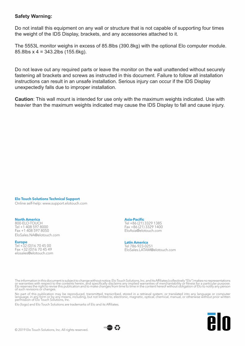
Step 1:Place the IDS face down on a padded surface and then install the upper and lower display brackets following step 2a or 2b.
Step 2a: Attach upper and lower display brackets (Landscape orientation)
• Secure the upper display bracket to the upper mounting pads using two M8x25 screws.
• Secure the lower display brackets to the two lower mounting location using two M8x25 screws. Ensure the hinged cable service brackets are oriented as shown.
• Proceed to step 3.Upper Display Bracket
Lower Display Bracket with hinged cable Service Bracket
I/O ConnectionsUpper Display Bracket
mounting location
Lower Display Bracket mounting location
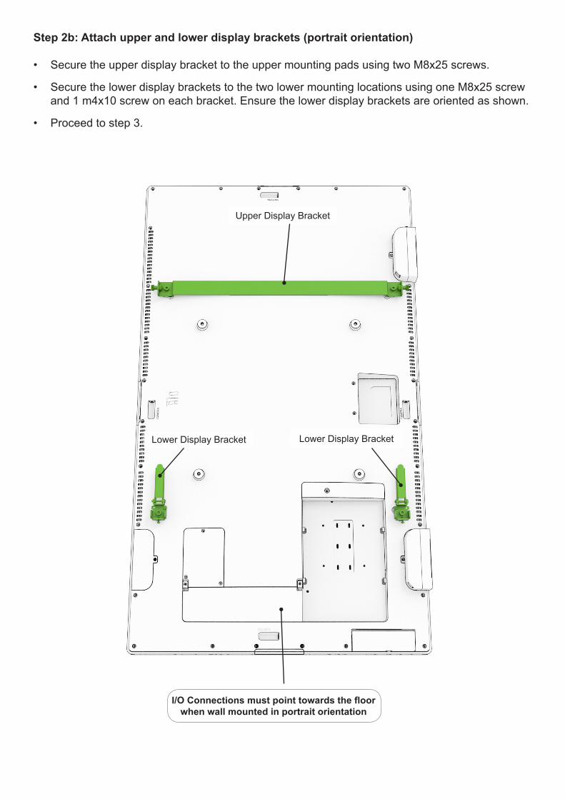
Step 2b: Attach upper and lower display brackets (portrait orientation)
• Secure the upper display bracket to the upper mounting pads using two M8x25 screws.
• Secure the lower display brackets to the two lower mounting locations using one M8x25 screw and 1 m4x10 screw on each bracket. Ensure the lower display brackets are oriented as shown.
• Proceed to step 3.
Upper Display Bracket
I/O Connections must point towards the floor when wall mounted in portrait orientation
Lower Display Bracket Lower Display Bracket
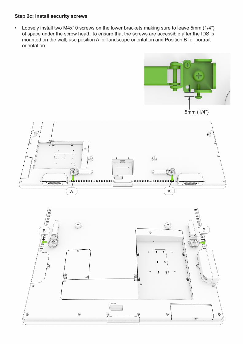
Step 2c: Install security screws
• Loosely install two M4x10 screws on the lower brackets making sure to leave 5mm (1/4”) of space under the screw head. To ensure that the screws are accessible after the IDS is mounted on the wall, use position A for landscape orientation and Position B for portrait orientation.
AA
B
5mm (1/4”)
B
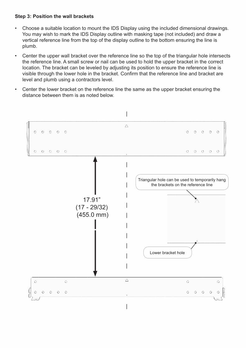
Step 3: Position the wall brackets
• Choose a suitable location to mount the IDS Display using the included dimensional drawings. You may wish to mark the IDS Display outline with masking tape (not included) and draw a vertical reference line from the top of the display outline to the bottom ensuring the line is plumb.
• Center the upper wall bracket over the reference line so the top of the triangular hole intersects the reference line. A small screw or nail can be used to hold the upper bracket in the correct location. The bracket can be leveled by adjusting its position to ensure the reference line is visible through the lower hole in the bracket. Confirm that the reference line and bracket are level and plumb using a contractors level.
• Center the lower bracket on the reference line the same as the upper bracket ensuring the distance between them is as noted below.
17.91” (17 - 29/32) (455.0 mm)
Triangular hole can be used to temporarily hang the brackets on the reference line
Lower bracket hole
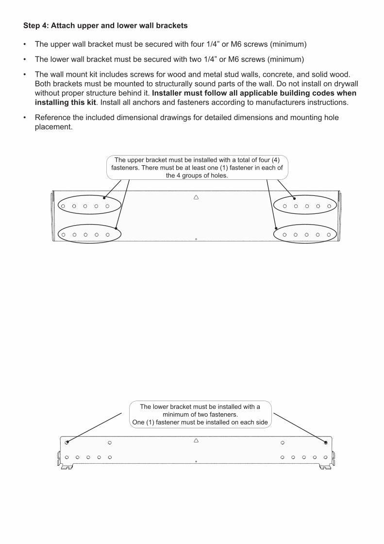
Step 4: Attach upper and lower wall brackets
• The upper wall bracket must be secured with four 1/4” or M6 screws (minimum)
• The lower wall bracket must be secured with two 1/4” or M6 screws (minimum)
• The wall mount kit includes screws for wood and metal stud walls, concrete, and solid wood. Both brackets must be mounted to structurally sound parts of the wall. Do not install on drywall without proper structure behind it. Installer must follow all applicable building codes when installing this kit. Install all anchors and fasteners according to manufacturers instructions.
• Reference the included dimensional drawings for detailed dimensions and mounting hole placement.
The lower bracket must be installed with a minimum of two fasteners.
One (1) fastener must be installed on each side
The upper bracket must be installed with a total of four (4) fasteners. There must be at least one (1) fastener in each of
the 4 groups of holes.
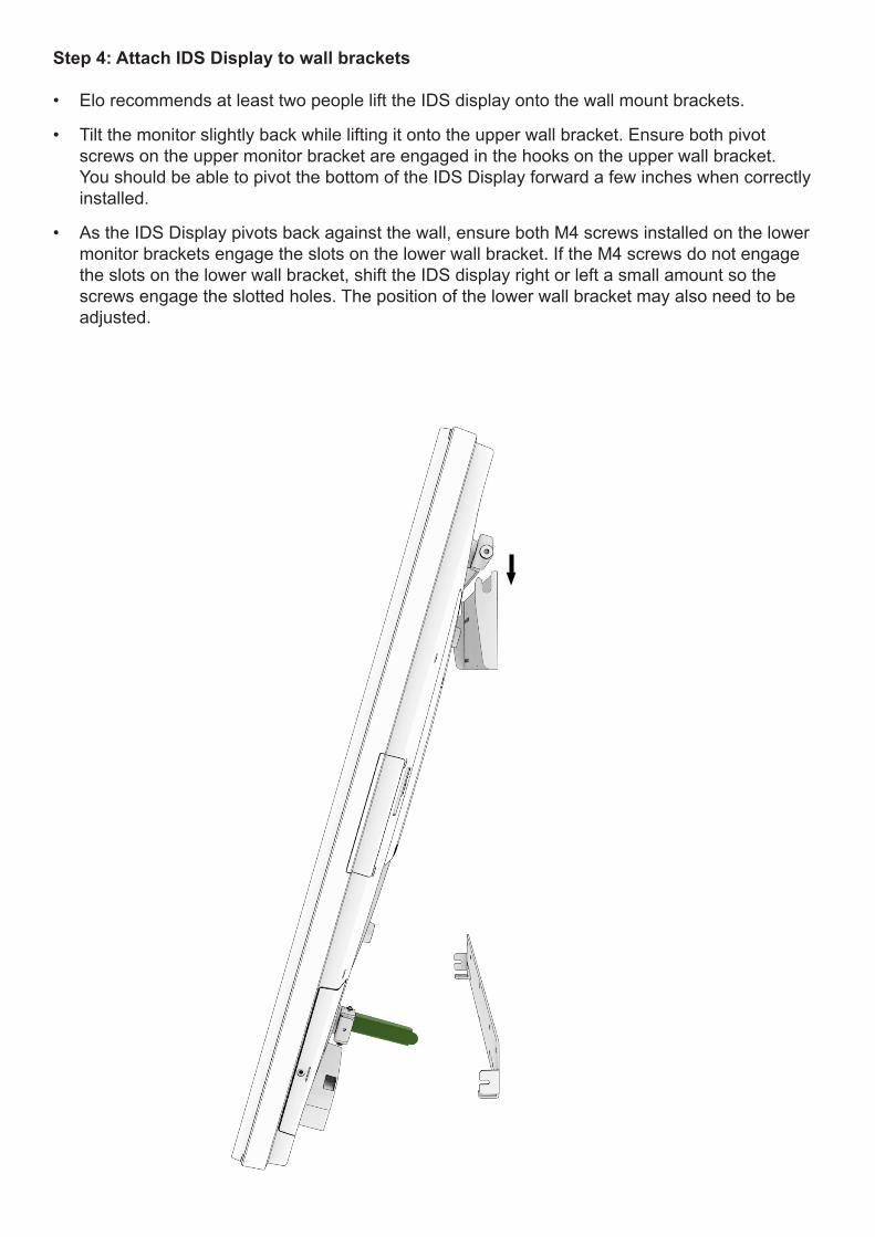
Step 4: Attach IDS Display to wall brackets • Elo recommends at least two people lift the IDS display onto the wall mount brackets.
• Tilt the monitor slightly back while lifting it onto the upper wall bracket. Ensure both pivot screws on the upper monitor bracket are engaged in the hooks on the upper wall bracket. You should be able to pivot the bottom of the IDS Display forward a few inches when correctly installed.
• As the IDS Display pivots back against the wall, ensure both M4 screws installed on the lower monitor brackets engage the slots on the lower wall bracket. If the M4 screws do not engage the slots on the lower wall bracket, shift the IDS display right or left a small amount so the screws engage the slotted holes. The position of the lower wall bracket may also need to be adjusted.
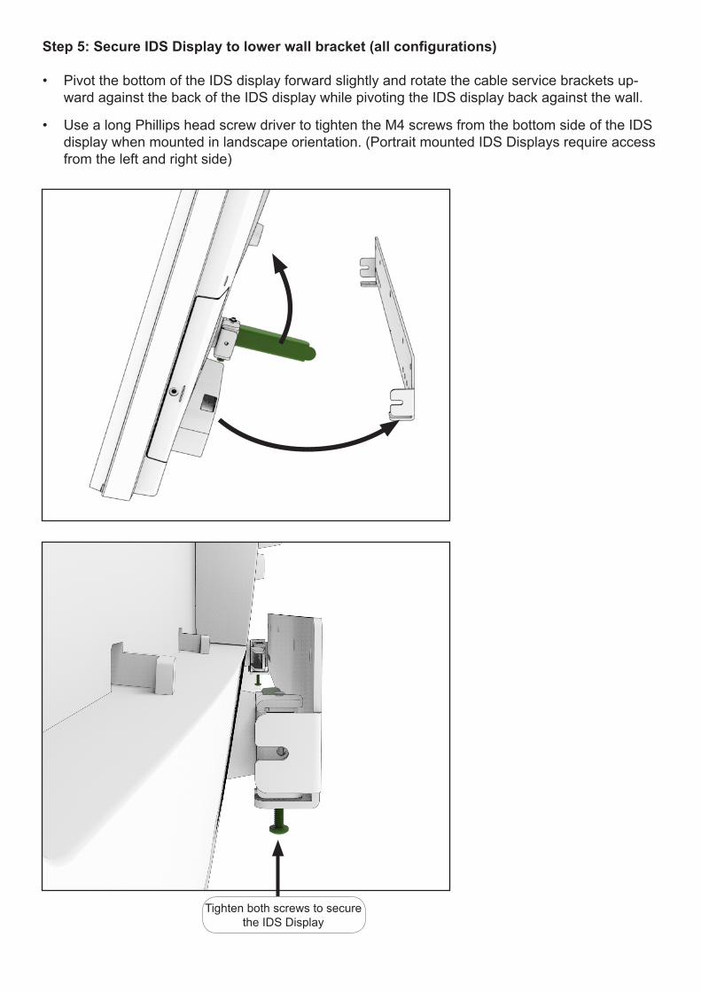
Step 5: Secure IDS Display to lower wall bracket (all configurations) • Pivot the bottom of the IDS display forward slightly and rotate the cable service brackets up-
ward against the back of the IDS display while pivoting the IDS display back against the wall.
• Use a long Phillips head screw driver to tighten the M4 screws from the bottom side of the IDS display when mounted in landscape orientation. (Portrait mounted IDS Displays require access from the left and right side)
Tighten both screws to secure the IDS Display
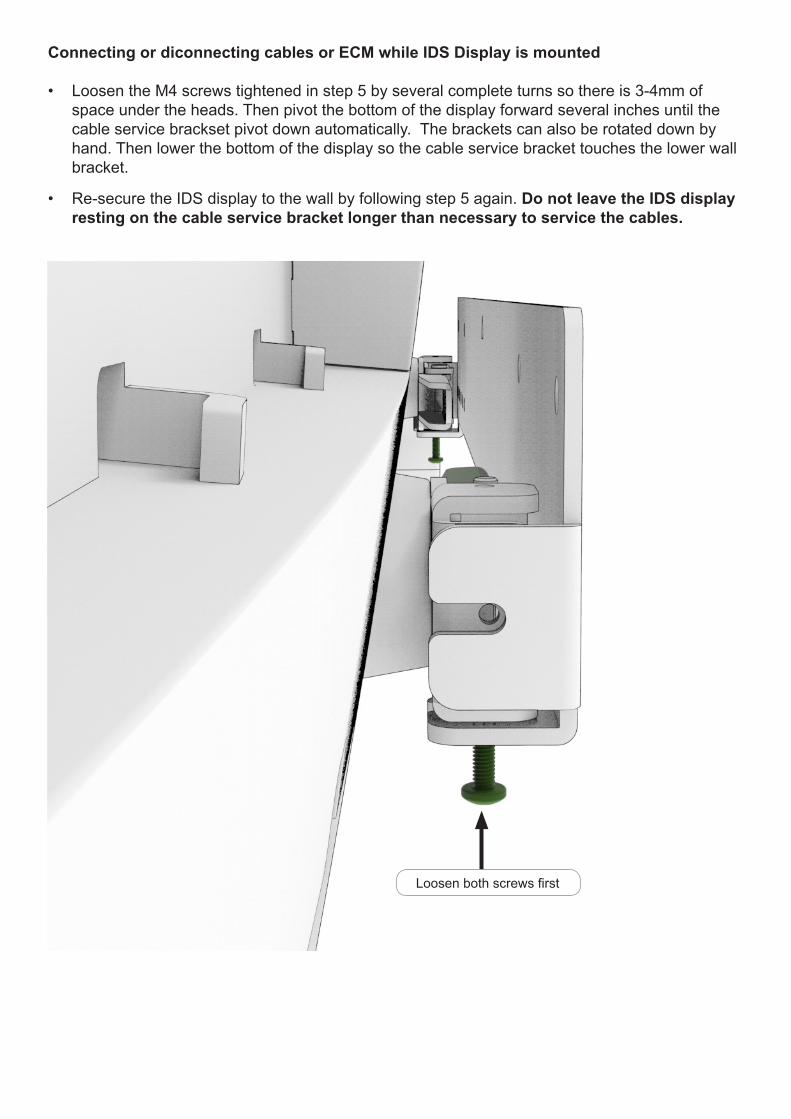
Connecting or diconnecting cables or ECM while IDS Display is mounted • Loosen the M4 screws tightened in step 5 by several complete turns so there is 3-4mm of
space under the heads. Then pivot the bottom of the display forward several inches until the cable service brackset pivot down automatically. The brackets can also be rotated down by hand. Then lower the bottom of the display so the cable service bracket touches the lower wall bracket.
• Re-secure the IDS display to the wall by following step 5 again. Do not leave the IDS display resting on the cable service bracket longer than necessary to service the cables.
Loosen both screws first
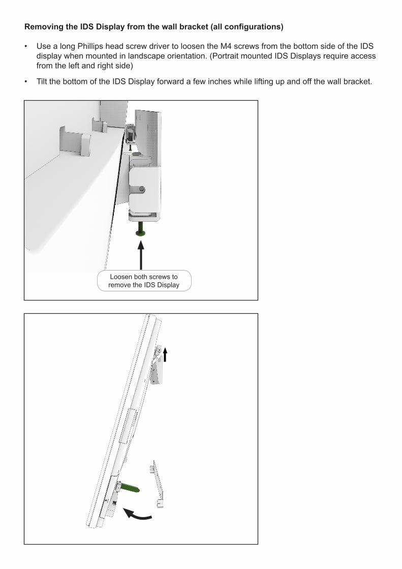
Removing the IDS Display from the wall bracket (all configurations) • Use a long Phillips head screw driver to loosen the M4 screws from the bottom side of the IDS
display when mounted in landscape orientation. (Portrait mounted IDS Displays require access from the left and right side)
• Tilt the bottom of the IDS Display forward a few inches while lifting up and off the wall bracket.
Loosen both screws to remove the IDS Display

![4 BAY Low Profile - SINGLE XL DISPLAY WALL MOUNT ......Salamander 4 Bay Low Profile Wall Mount Cabinet with XL Display Mount 15 of 30 503-030 [10.17] Main Adjustment (Side to Side](https://img.pdfslide.us/doc/110x75/6071a3b9320c4c78a16c1492/4-bay-low-profile-single-xl-display-wall-mount-salamander-4-bay-low-profile.jpg)