Embed Size (px)
Citation preview
Rev 3.5Page 1 of 14
Level Developments Ltd.97-99 Gloucester Road
Croydon, Surrey, CR0 2DNUnited Kingdom
t : +44 (0)20 8684 1400f : +44 (0)20 8684 1422
IDS : Inclinometer Display System with RS232 Output
FeaturesGraphic Dual Axis Mode Dual Axis Mode Single Axis Mode
The IDS is a high quality display system for use with many
of our inclinometer sensors. It has a sturdy Aluminium
housing which is sealed to IP67 and utilises high perform-
ance sealed locking connectors. It has a graphical OLED
display for high contrast and wide viewing angle. This
enables it to have an extended temperature range
(compared with LCD displays), and can be used in low light
or night-time applications. It has a built in Li-Po battery
which can power the unit and the attached inclinometer
sensor for 30 hours between charges. The display can be
switched between single axis, dual axis and graphical
measurement modes, and the displayed angle can be
configured with one, two or three decimal places. It is
supplied with a mains charger, which is also fitted with a
sealed connector. Without the battery fitted, the charger
will power the device directly. It has an RS232 interface and
a versatile programmable alarm function with switched
relay outputs.
· OLED Graphical Display. High contrast with
wide viewing angle.
· Single, dual axis or graphical display mode
· RS232 interface for onward connection
· Programmable alarm function (relay output)
· Built in Li-Po rechargeable battery (30 hours
continuous use)
· Compatible with many of our inclinometers
· Display resolution 0.001° (adjustable to 1, 2 or
3 decimal places)
· Sturdy aluminium Housing, sealed to IP67 with
IP67 locking connectors
· Temperature range -40 to +85°C (without
internal battery)
· Absolute and Relative measurement
· Hold button to freeze current reading
Description Features
Rev 3.5Page 2 of 14
Level Developments Ltd.97-99 Gloucester Road
Croydon, Surrey, CR0 2DNUnited Kingdom
t : +44 (0)20 8684 1400f : +44 (0)20 8684 1422
IDS : Inclinometer Display System with RS232 Output
Product Features
RS232 Interface
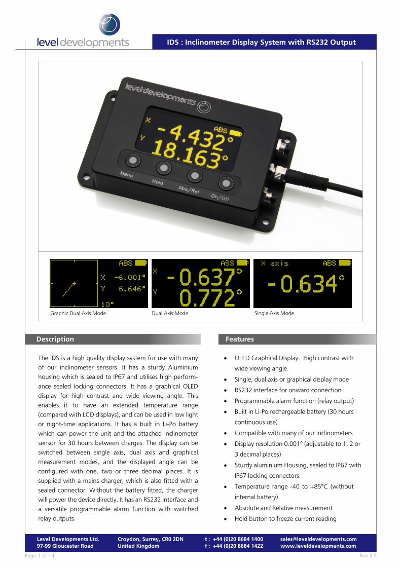
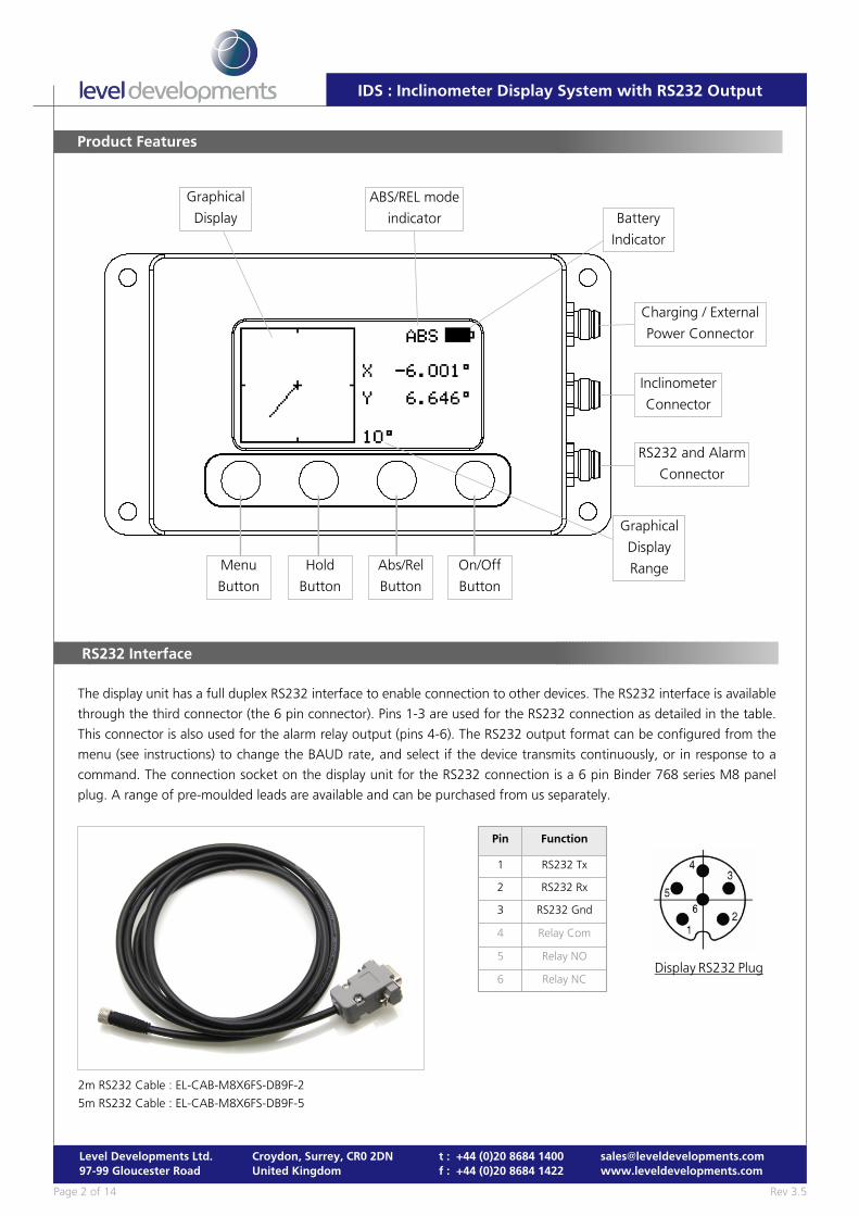
The display unit has a full duplex RS232 interface to enable connection to other devices. The RS232 interface is available
through the third connector (the 6 pin connector). Pins 1-3 are used for the RS232 connection as detailed in the table.
This connector is also used for the alarm relay output (pins 4-6). The RS232 output format can be configured from the
menu (see instructions) to change the BAUD rate, and select if the device transmits continuously, or in response to a
command. The connection socket on the display unit for the RS232 connection is a 6 pin Binder 768 series M8 panel
plug. A range of pre-moulded leads are available and can be purchased from us separately.
Pin Function
1 RS232 Tx
2 RS232 Rx
3 RS232 Gnd
4 Relay Com
5 Relay NO
6 Relay NC
Charging / External
Power Connector
Inclinometer
Connector
Battery
Indicator
ABS/REL mode
indicator
On/Off
Button
Abs/Rel
Button
Hold
Button
Graphical
Display
Menu
Button
Graphical
Display
Range
RS232 and Alarm
Connector
2m RS232 Cable : EL-CAB-M8X6FS-DB9F-2
5m RS232 Cable : EL-CAB-M8X6FS-DB9F-5
Display RS232 Plug
Rev 3.5Page 3 of 14
Level Developments Ltd.97-99 Gloucester Road
Croydon, Surrey, CR0 2DNUnited Kingdom
t : +44 (0)20 8684 1400f : +44 (0)20 8684 1422
IDS : Inclinometer Display System with RS232 Output
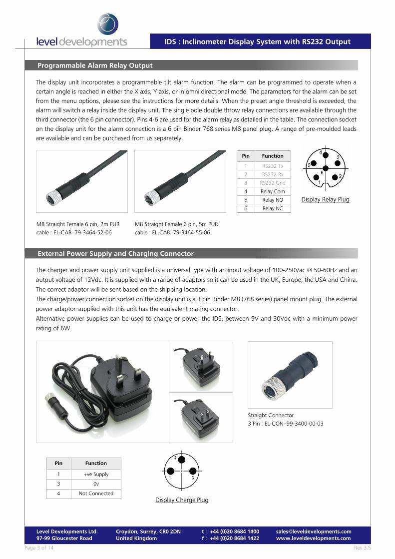
Programmable Alarm Relay Output
The display unit incorporates a programmable tilt alarm function. The alarm can be programmed to operate when a
certain angle is reached in either the X axis, Y axis, or in omni directional mode. The parameters for the alarm can be set
from the menu options, please see the instructions for more details. When the preset angle threshold is exceeded, the
alarm will switch a relay inside the display unit. The single pole double throw relay connections are available through the
third connector (the 6 pin connector). Pins 4-6 are used for the alarm relay as detailed in the table. The connection socket
on the display unit for the alarm connection is a 6 pin Binder 768 series M8 panel plug. A range of pre-moulded leads
are available and can be purchased from us separately.
Pin Function
1 RS232 Tx
2 RS232 Rx
3 RS232 Gnd
4 Relay Com
5 Relay NO
6 Relay NC
M8 Straight Female 6 pin, 2m PUR
cable : EL-CAB–79-3464-52-06
M8 Straight Female 6 pin, 5m PUR
cable : EL-CAB–79-3464-55-06
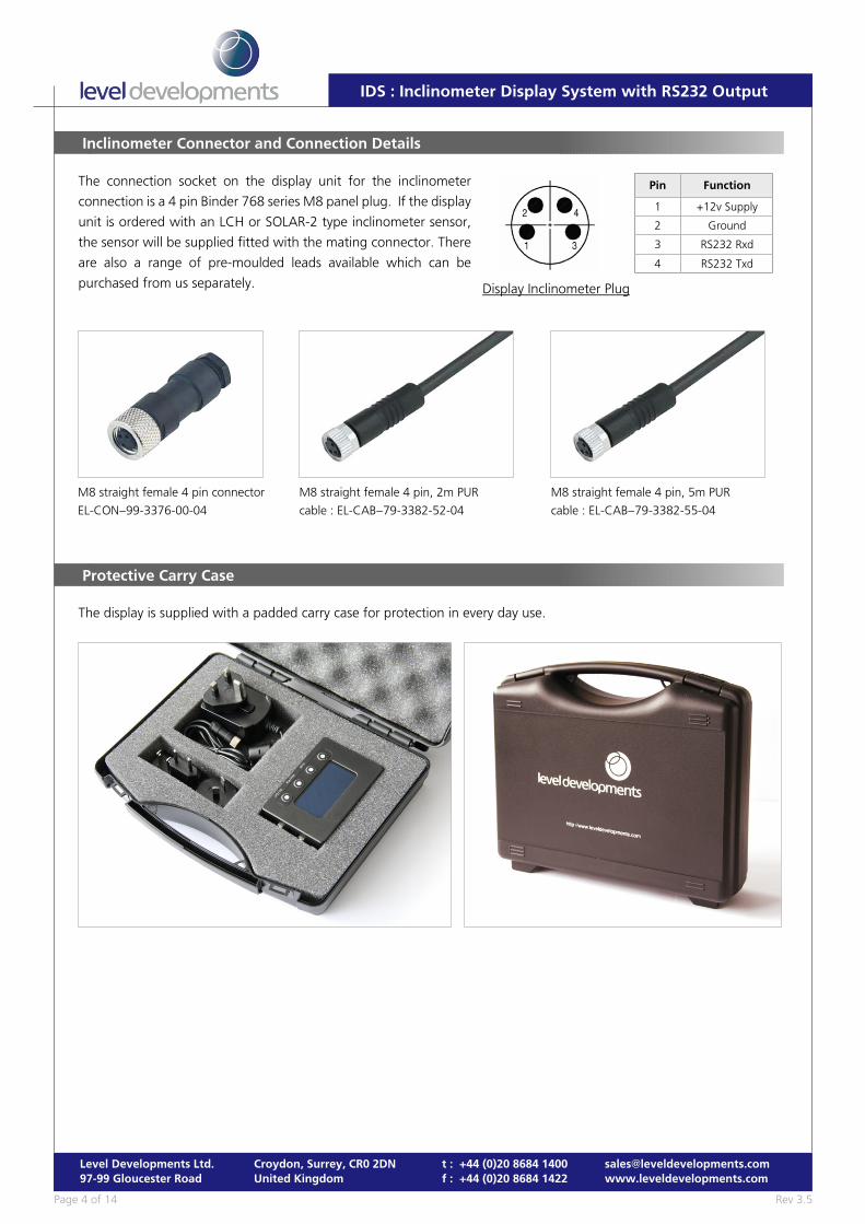
External Power Supply and Charging Connector
The charger and power supply unit supplied is a universal type with an input voltage of 100-250Vac @ 50-60Hz and an
output voltage of 12Vdc. It is supplied with a range of adaptors so it can be used in the UK, Europe, the USA and China.
The correct adaptor will be sent based on the shipping location.
The charge/power connection socket on the display unit is a 3 pin Binder M8 (768 series) panel mount plug. The external
power adaptor supplied with this unit has the equivalent mating connector.
Alternative power supplies can be used to charge or power the IDS, between 9V and 30Vdc with a minimum power
rating of 6W.
Display Relay Plug
Straight Connector
3 Pin : EL-CON–99-3400-00-03
Display Charge Plug
Pin Function
1 +ve Supply
3 0v
4 Not Connected
Rev 3.5Page 4 of 14
Level Developments Ltd.97-99 Gloucester Road
Croydon, Surrey, CR0 2DNUnited Kingdom
t : +44 (0)20 8684 1400f : +44 (0)20 8684 1422
IDS : Inclinometer Display System with RS232 Output
M8 straight female 4 pin connector
EL-CON–99-3376-00-04
M8 straight female 4 pin, 2m PUR
cable : EL-CAB–79-3382-52-04
M8 straight female 4 pin, 5m PUR
cable : EL-CAB–79-3382-55-04
Protective Carry Case
The display is supplied with a padded carry case for protection in every day use.
Inclinometer Connector and Connection Details
The connection socket on the display unit for the inclinometer
connection is a 4 pin Binder 768 series M8 panel plug. If the display
unit is ordered with an LCH or SOLAR-2 type inclinometer sensor,
the sensor will be supplied fitted with the mating connector. There
are also a range of pre-moulded leads available which can be
purchased from us separately.
Pin Function
1 +12v Supply
2 Ground
3 RS232 Rxd
4 RS232 Txd
Display Inclinometer Plug
Rev 3.5Page 5 of 14
Level Developments Ltd.97-99 Gloucester Road
Croydon, Surrey, CR0 2DNUnited Kingdom
t : +44 (0)20 8684 1400f : +44 (0)20 8684 1422
IDS : Inclinometer Display System with RS232 Output
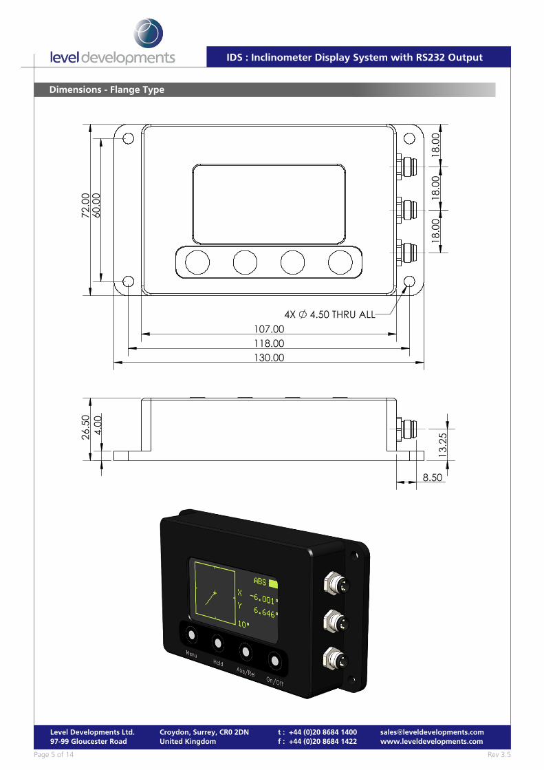
Dimensions - Flange Type
107.00
18.0
018
.00
18.0
0
130.00
4X 4.50 THRU ALL
118.00
60.0
072
.00
8.50
13.2
526.5
04.
00
Rev 3.5Page 6 of 14
Level Developments Ltd.97-99 Gloucester Road
Croydon, Surrey, CR0 2DNUnited Kingdom
t : +44 (0)20 8684 1400f : +44 (0)20 8684 1422
IDS : Inclinometer Display System with RS232 Output
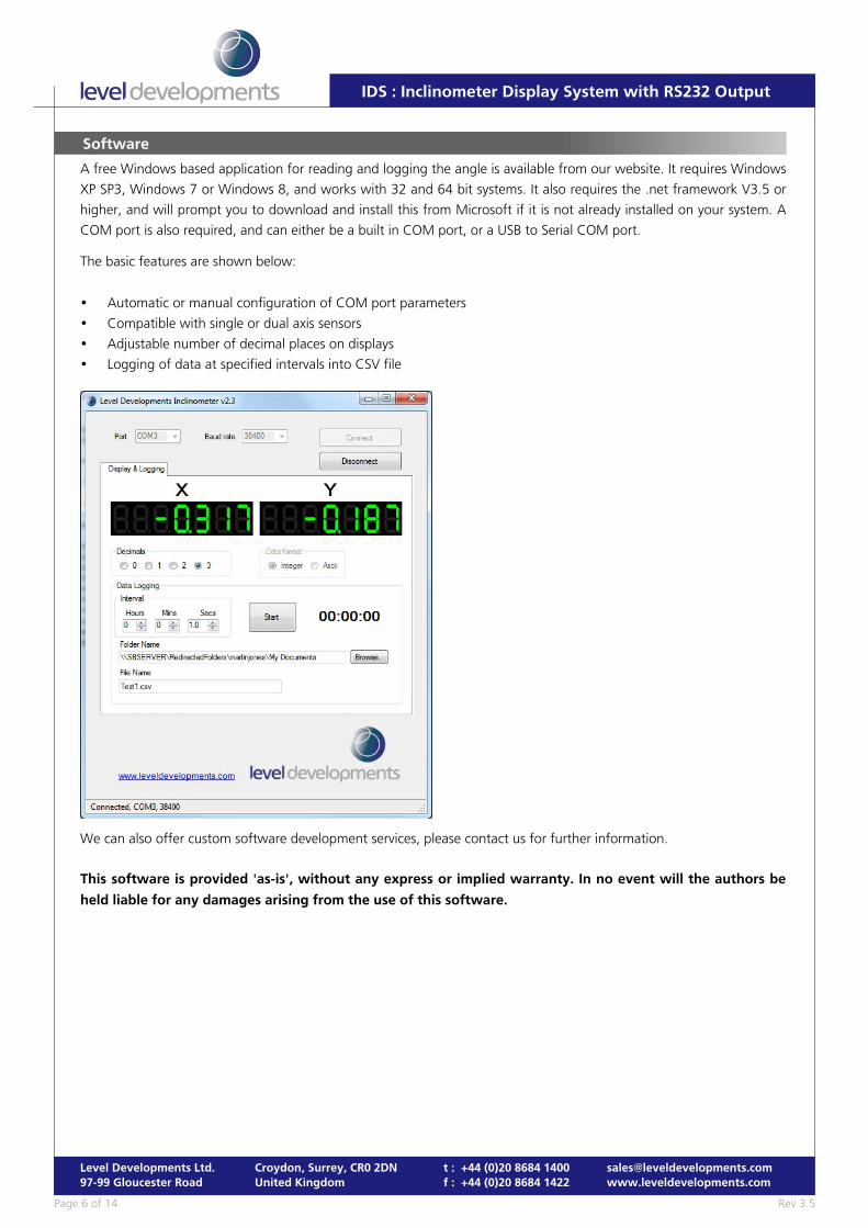
A free Windows based application for reading and logging the angle is available from our website. It requires Windows
XP SP3, Windows 7 or Windows 8, and works with 32 and 64 bit systems. It also requires the .net framework V3.5 or
higher, and will prompt you to download and install this from Microsoft if it is not already installed on your system. A
COM port is also required, and can either be a built in COM port, or a USB to Serial COM port.
The basic features are shown below:
� Automatic or manual configuration of COM port parameters
� Compatible with single or dual axis sensors
� Adjustable number of decimal places on displays
� Logging of data at specified intervals into CSV file
We can also offer custom software development services, please contact us for further information.
This software is provided 'as-is', without any express or implied warranty. In no event will the authors be
held liable for any damages arising from the use of this software.
Software
Rev 3.5Page 7 of 14
Level Developments Ltd.97-99 Gloucester Road
Croydon, Surrey, CR0 2DNUnited Kingdom
t : +44 (0)20 8684 1400f : +44 (0)20 8684 1422
IDS : Inclinometer Display System with RS232 Output
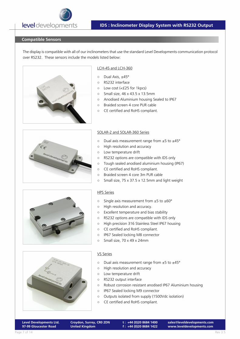
Compatible Sensors
The display is compatible with all of our inclinometers that use the standard Level Developments communication protocol
over RS232. These sensors include the models listed below:
LCH-45 and LCH-360
○ Dual Axis, ±45°
○ RS232 interface
○ Low cost (<£25 for 1kpcs)
○ Small size, 46 x 43.5 x 13.5mm
○ Anodised Aluminium housing Sealed to IP67
○ Braided screen 4 core PUR cable
○ CE certified and RoHS compliant.
SOLAR-2 and SOLAR-360 Series
○ Dual axis measurement range from ±5 to ±45°
○ High resolution and accuracy
○ Low temperature drift
○ RS232 options are compatible with IDS only
○ Tough sealed anodised aluminium housing (IP67)
○ CE certified and RoHS compliant.
○ Braided screen 4 core 3m PUR cable
○ Small size, 75 x 37.5 x 12.5mm and light weight
VS Series
○ Dual axis measurement range from ±5 to ±45°
○ High resolution and accuracy
○ Low temperature drift
○ RS232 output interface
○ Robust corrosion resistant anodised IP67 Aluminium housing
○ IP67 Sealed locking M9 connector
○ Outputs isolated from supply (1500Vdc isolation)
○ CE certified and RoHS compliant.
HPS Series
○ Single axis measurement from ±5 to ±60°
○ High resolution and accuracy.
○ Excellent temperature and bias stability
○ RS232 options are compatible with IDS only
○ High precision 316 Stainless Steel IP67 housing
○ CE certified and RoHS compliant.
○ IP67 Sealed locking M8 connector
○ Small size, 70 x 49 x 24mm
Rev 3.5Page 8 of 14
Level Developments Ltd.97-99 Gloucester Road
Croydon, Surrey, CR0 2DNUnited Kingdom
t : +44 (0)20 8684 1400f : +44 (0)20 8684 1422
IDS : Inclinometer Display System with RS232 Output
Instructions for Use
To Switch On
Press and hold the On/Off Button for at least 1 second and then release. The device will now switch on.
To Switch Off
Press and hold the On/Off Button for at least 5 seconds. After 5 seconds the device will switch off.
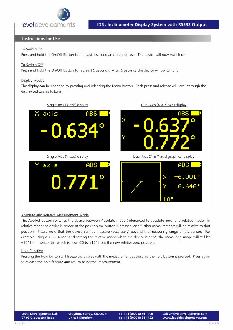
Display Modes
The display can be changed by pressing and releasing the Menu button. Each press and release will scroll through the
display options as follows:
Single Axis (X axis) display
Single Axis (Y axis) display
Dual Axis (X & Y axis) display
Dual Axis (X & Y axis) graphical display
Absolute and Relative Measurement Mode
The Abs/Rel button switches the device between Absolute mode (referenced to absolute zero) and relative mode. In
relative mode the device is zeroed at the position the button is pressed, and further measurements will be relative to that
position. Please note that the device cannot measure (accurately) beyond the measuring range of the sensor. For
example using a ±15° sensor and setting the relative mode when the device is at 5°, the measuring range will still be
±15° from horizontal, which is now -20 to +10° from the new relative zero position.
Hold Function
Pressing the Hold button will freeze the display with the measurement at the time the hold button is pressed. Press again
to release the hold feature and return to normal measurement.
Rev 3.5Page 9 of 14
Level Developments Ltd.97-99 Gloucester Road
Croydon, Surrey, CR0 2DNUnited Kingdom
t : +44 (0)20 8684 1400f : +44 (0)20 8684 1422
IDS : Inclinometer Display System with RS232 Output
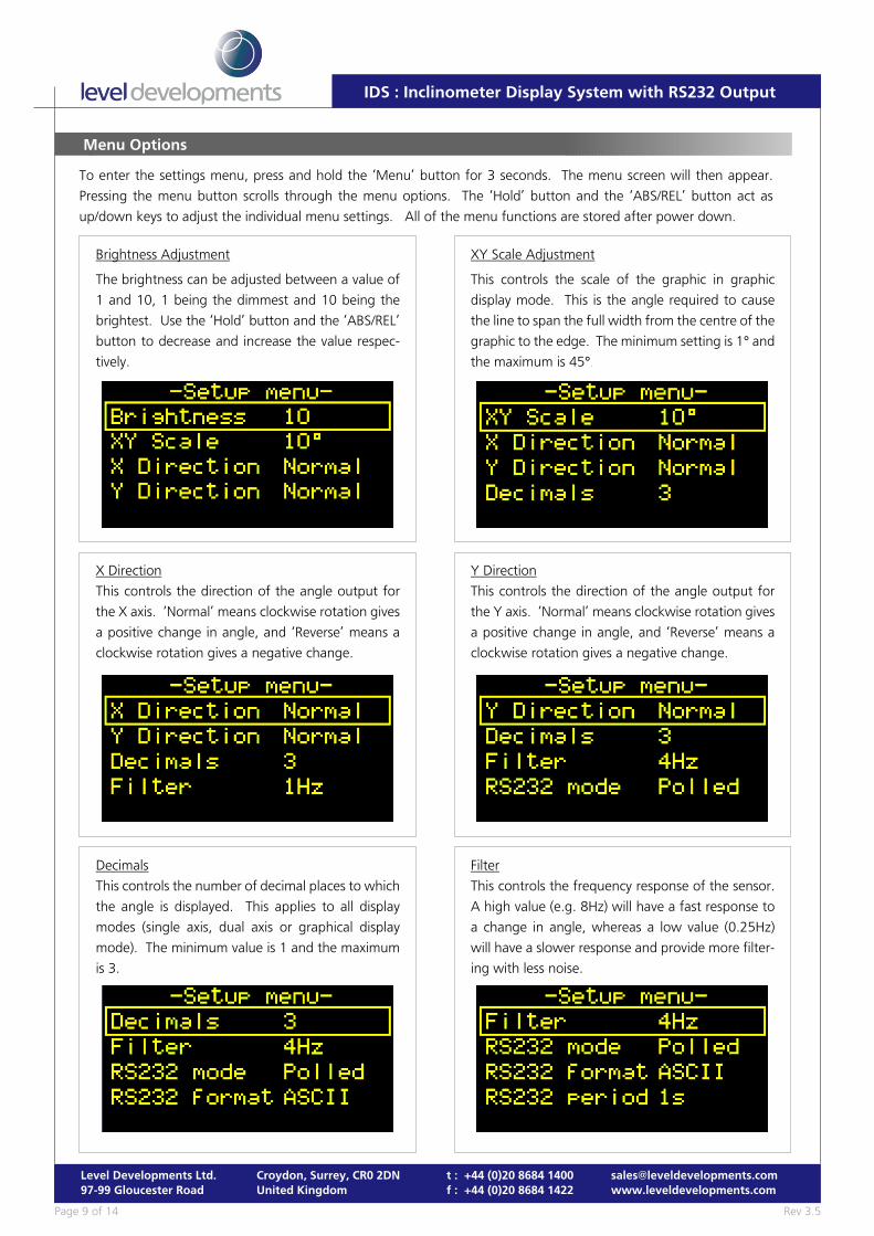
Menu Options
To enter the settings menu, press and hold the ‘Menu’ button for 3 seconds. The menu screen will then appear.
Pressing the menu button scrolls through the menu options. The ‘Hold’ button and the ‘ABS/REL’ button act as
up/down keys to adjust the individual menu settings. All of the menu functions are stored after power down.
XY Scale Adjustment
This controls the scale of the graphic in graphic
display mode. This is the angle required to cause
the line to span the full width from the centre of the
graphic to the edge. The minimum setting is 1° and
the maximum is 45°.
X Direction
This controls the direction of the angle output for
the X axis. ‘Normal’ means clockwise rotation gives
a positive change in angle, and ‘Reverse’ means a
clockwise rotation gives a negative change.
Brightness Adjustment
The brightness can be adjusted between a value of
1 and 10, 1 being the dimmest and 10 being the
brightest. Use the ‘Hold’ button and the ‘ABS/REL’
button to decrease and increase the value respec-
tively.
Y Direction
This controls the direction of the angle output for
the Y axis. ‘Normal’ means clockwise rotation gives
a positive change in angle, and ‘Reverse’ means a
clockwise rotation gives a negative change.
Decimals
This controls the number of decimal places to which
the angle is displayed. This applies to all display
modes (single axis, dual axis or graphical display
mode). The minimum value is 1 and the maximum
is 3.
Filter
This controls the frequency response of the sensor.
A high value (e.g. 8Hz) will have a fast response to
a change in angle, whereas a low value (0.25Hz)
will have a slower response and provide more filter-
ing with less noise.
Rev 3.5Page 10 of 14
Level Developments Ltd.97-99 Gloucester Road
Croydon, Surrey, CR0 2DNUnited Kingdom
t : +44 (0)20 8684 1400f : +44 (0)20 8684 1422
IDS : Inclinometer Display System with RS232 Output
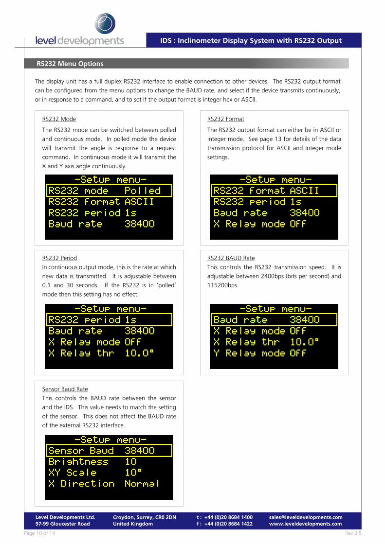
RS232 Menu Options
The display unit has a full duplex RS232 interface to enable connection to other devices. The RS232 output format
can be configured from the menu options to change the BAUD rate, and select if the device transmits continuously,
or in response to a command, and to set if the output format is integer hex or ASCII.
RS232 Format
The RS232 output format can either be in ASCII or
integer mode. See page 13 for details of the data
transmission protocol for ASCII and Integer mode
settings.
RS232 Period
In continuous output mode, this is the rate at which
new data is transmitted. It is adjustable between
0.1 and 30 seconds. If the RS232 is in ‘polled’
mode then this setting has no effect.
RS232 Mode
The RS232 mode can be switched between polled
and continuous mode. In polled mode the device
will transmit the angle is response to a request
command. In continuous mode it will transmit the
X and Y axis angle continuously.
RS232 BAUD Rate
This controls the RS232 transmission speed. It is
adjustable between 2400bps (bits per second) and
115200bps.
Sensor Baud Rate
This controls the BAUD rate between the sensor
and the IDS. This value needs to match the setting
of the sensor. This does not affect the BAUD rate
of the external RS232 interface.
Rev 3.5Page 11 of 14
Level Developments Ltd.97-99 Gloucester Road
Croydon, Surrey, CR0 2DNUnited Kingdom
t : +44 (0)20 8684 1400f : +44 (0)20 8684 1422
IDS : Inclinometer Display System with RS232 Output
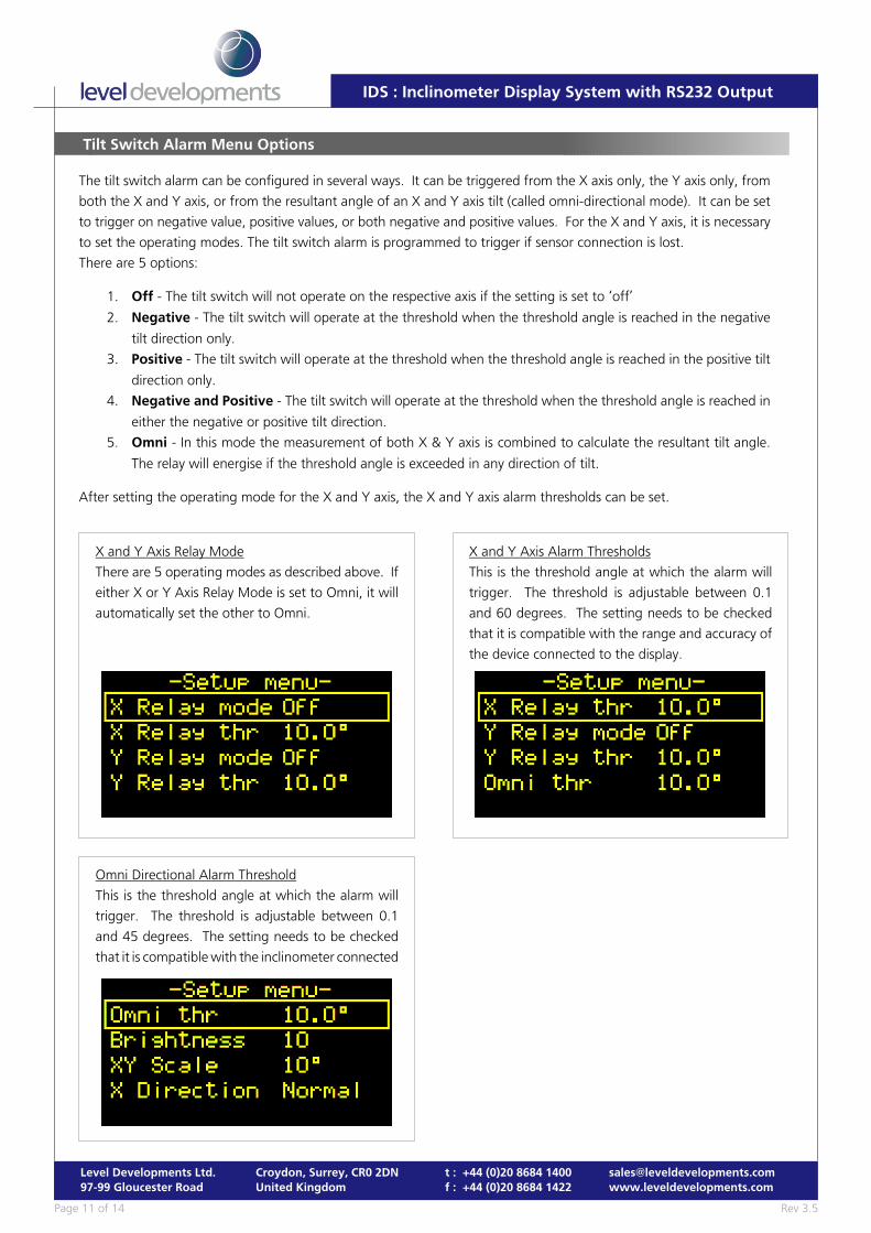
Tilt Switch Alarm Menu Options
The tilt switch alarm can be configured in several ways. It can be triggered from the X axis only, the Y axis only, from
both the X and Y axis, or from the resultant angle of an X and Y axis tilt (called omni-directional mode). It can be set
to trigger on negative value, positive values, or both negative and positive values. For the X and Y axis, it is necessary
to set the operating modes. The tilt switch alarm is programmed to trigger if sensor connection is lost.
There are 5 options:
1. Off - The tilt switch will not operate on the respective axis if the setting is set to ‘off’
2. Negative - The tilt switch will operate at the threshold when the threshold angle is reached in the negative
tilt direction only.
3. Positive - The tilt switch will operate at the threshold when the threshold angle is reached in the positive tilt
direction only.
4. Negative and Positive - The tilt switch will operate at the threshold when the threshold angle is reached in
either the negative or positive tilt direction.
5. Omni - In this mode the measurement of both X & Y axis is combined to calculate the resultant tilt angle.
The relay will energise if the threshold angle is exceeded in any direction of tilt.
After setting the operating mode for the X and Y axis, the X and Y axis alarm thresholds can be set.
X and Y Axis Relay Mode
There are 5 operating modes as described above. If
either X or Y Axis Relay Mode is set to Omni, it will
automatically set the other to Omni.
X and Y Axis Alarm Thresholds
This is the threshold angle at which the alarm will
trigger. The threshold is adjustable between 0.1
and 60 degrees. The setting needs to be checked
that it is compatible with the range and accuracy of
the device connected to the display.
Omni Directional Alarm Threshold
This is the threshold angle at which the alarm will
trigger. The threshold is adjustable between 0.1
and 45 degrees. The setting needs to be checked
that it is compatible with the inclinometer connected
Rev 3.5Page 12 of 14
Level Developments Ltd.97-99 Gloucester Road
Croydon, Surrey, CR0 2DNUnited Kingdom
t : +44 (0)20 8684 1400f : +44 (0)20 8684 1422
IDS : Inclinometer Display System with RS232 Output
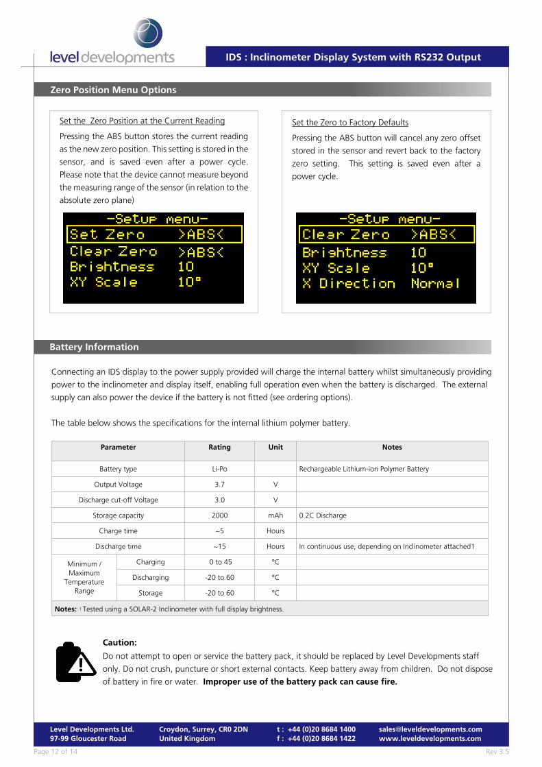
Zero Position Menu Options
Set the Zero to Factory Defaults
Pressing the ABS button will cancel any zero offset
stored in the sensor and revert back to the factory
zero setting. This setting is saved even after a
power cycle.
Set the Zero Position at the Current Reading
Pressing the ABS button stores the current reading
as the new zero position. This setting is stored in the
sensor, and is saved even after a power cycle.
Please note that the device cannot measure beyond
the measuring range of the sensor (in relation to the
absolute zero plane)
Battery Information
Connecting an IDS display to the power supply provided will charge the internal battery whilst simultaneously providing
power to the inclinometer and display itself, enabling full operation even when the battery is discharged. The external
supply can also power the device if the battery is not fitted (see ordering options).
The table below shows the specifications for the internal lithium polymer battery.
Parameter Rating Unit Notes
Battery type Li-Po Rechargeable Lithium-ion Polymer Battery
Output Voltage 3.7 V
Discharge cut-off Voltage 3.0 V
Storage capacity 2000 mAh 0.2C Discharge
Charge time ~5 Hours
Discharge time ~15 Hours In continuous use, depending on Inclinometer attached1
Minimum /Maximum
TemperatureRange
Charging 0 to 45 °C
Discharging -20 to 60 °C
Storage -20 to 60 °C
Notes:: 1 Tested using a SOLAR-2 Inclinometer with full display brightness.
Caution:
Do not attempt to open or service the battery pack, it should be replaced by Level Developments staff
only. Do not crush, puncture or short external contacts. Keep battery away from children. Do not dispose
of battery in fire or water. Improper use of the battery pack can cause fire.
Rev 3.5Page 13 of 14
Level Developments Ltd.97-99 Gloucester Road
Croydon, Surrey, CR0 2DNUnited Kingdom
t : +44 (0)20 8684 1400f : +44 (0)20 8684 1422
IDS : Inclinometer Display System with RS232 Output
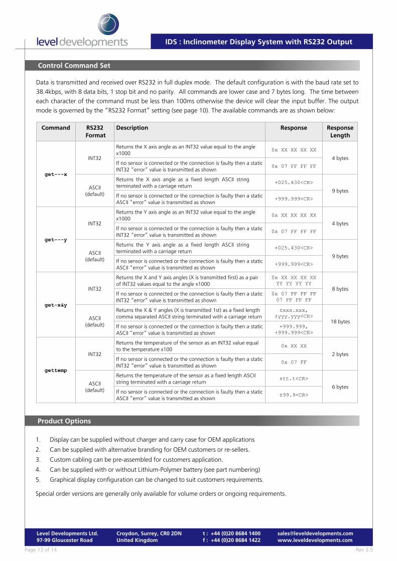
Control Command Set
Data is transmitted and received over RS232 in full duplex mode. The default configuration is with the baud rate set to
38.4kbps, with 8 data bits, 1 stop bit and no parity. All commands are lower case and 7 bytes long. The time between
each character of the command must be less than 100ms otherwise the device will clear the input buffer. The output
mode is governed by the “RS232 Format” setting (see page 10). The available commands are as shown below:
Command RS232 Format
Description Response ResponseLength
get---x
INT32
Returns the X axis angle as an INT32 value equal to the anglex1000
0x XX XX XX XX
4 bytesIf no sensor is connected or the connection is faulty then a staticINT32 “error” value is transmitted as shown
0x 07 FF FF FF
ASCII(default)
Returns the X axis angle as a fixed length ASCII stringterminated with a carriage return
+025.430<CR>
9 bytesIf no sensor is connected or the connection is faulty then a staticASCII “error” value is transmitted as shown
+999.999<CR>
get---y
INT32
Returns the Y axis angle as an INT32 value equal to the anglex1000
0x XX XX XX XX
4 bytesIf no sensor is connected or the connection is faulty then a staticINT32 “error” value is transmitted as shown
0x 07 FF FF FF
ASCII(default)
Returns the Y axis angle as a fixed length ASCII stringterminated with a carriage return
+025.430<CR>
9 bytesIf no sensor is connected or the connection is faulty then a staticASCII “error” value is transmitted as shown
+999.999<CR>
get-x&y
INT32
Returns the X and Y axis angles (X is transmitted first) as a pairof INT32 values equal to the angle x1000
0x XX XX XX XXYY YY YY YY
8 bytesIf no sensor is connected or the connection is faulty then a staticINT32 “error” value is transmitted as shown
0x 07 FF FF FF07 FF FF FF
ASCII(default)
Returns the X & Y angles (X is transmitted 1st) as a fixed lengthcomma separated ASCII string terminated with a carriage return
±xxx.xxx,±yyy.yyy<CR>
18 bytesIf no sensor is connected or the connection is faulty then a staticASCII “error” value is transmitted as shown
+999.999,+999.999<CR>
gettemp
INT32
Returns the temperature of the sensor as an INT32 value equalto the temperature x100
0x XX XX
2 bytesIf no sensor is connected or the connection is faulty then a staticINT32 “error” value is transmitted as shown
0x 07 FF
ASCII(default)
Returns the temperature of the sensor as a fixed length ASCIIstring terminated with a carriage return
±tt.t<CR>
6 bytesIf no sensor is connected or the connection is faulty then a staticASCII “error” value is transmitted as shown
±99.9<CR>
1. Display can be supplied without charger and carry case for OEM applications
2. Can be supplied with alternative branding for OEM customers or re-sellers.
3. Custom cabling can be pre-assembled for customers application.
4. Can be supplied with or without Lithium-Polymer battery (see part numbering)
5. Graphical display configuration can be changed to suit customers requirements.
Special order versions are generally only available for volume orders or ongoing requirements.
Product Options
Rev 3.5Page 14 of 14
Level Developments Ltd.97-99 Gloucester Road
Croydon, Surrey, CR0 2DNUnited Kingdom
t : +44 (0)20 8684 1400f : +44 (0)20 8684 1422
IDS : Inclinometer Display System with RS232 Output
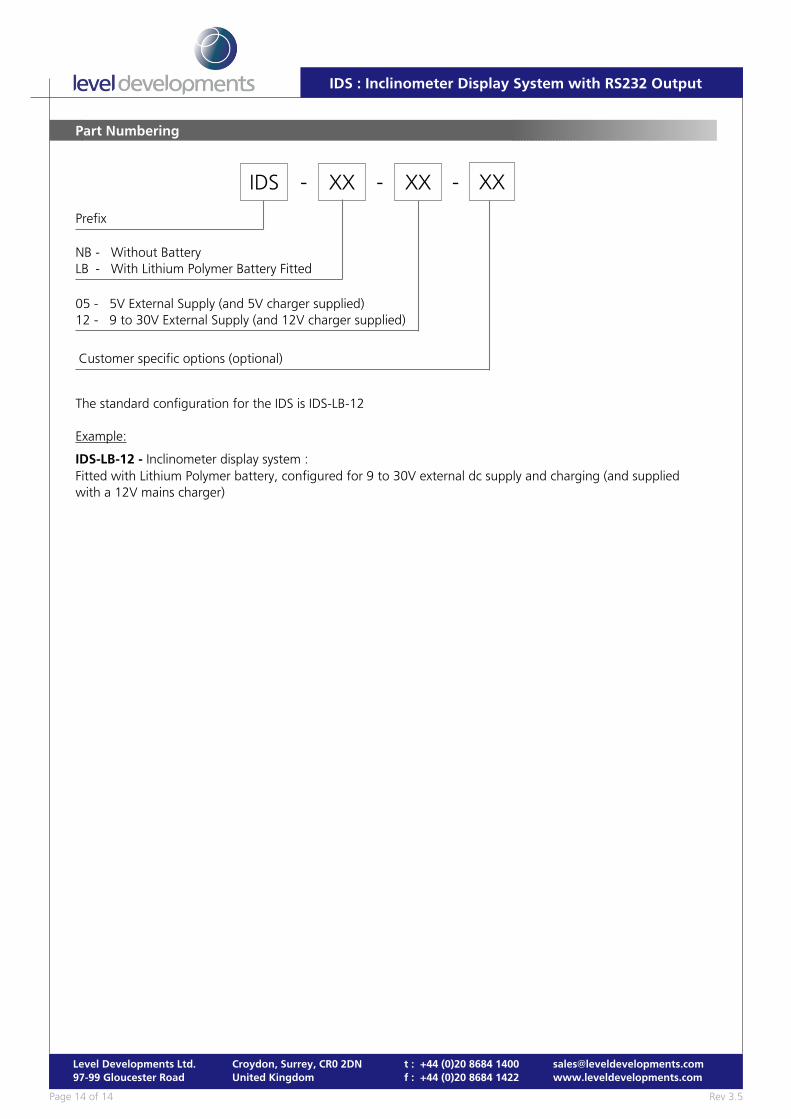
Part Numbering
IDS XX- XX- -
Prefix
NB - Without BatteryLB - With Lithium Polymer Battery Fitted
Customer specific options (optional)
05 - 5V External Supply (and 5V charger supplied)12 - 9 to 30V External Supply (and 12V charger supplied)
The standard configuration for the IDS is IDS-LB-12
Example:
IDS-LB-12 - Inclinometer display system :Fitted with Lithium Polymer battery, configured for 9 to 30V external dc supply and charging (and suppliedwith a 12V mains charger)
XX